

Page 1
Congratulations!
You are the proud owner of a Yamaha MFC06 MIDI Foot Controller. The
MFC06 offers convenient foot control of the Yamaha FX500 SIMUL-
EFFECT PROCESSOR: direct footswkch selection of up to 5 different effect
programs and ON/OFF switching of the COMPRESSOR, DISTORTION,
EQ, MODULATION and REVERB stages. The MFC06 is built to Yamaha's
rigid quality standards, and wilt provide reliable service for many years if
handled properly.
Please read this operation manual thoroughly before setting up and using
your MFC06.
PRECAUTIONS_________________________
1. AVOID EXCESSIVE HEAT. HUMIDITY, DUST AND VIBRATION
Keep the unit away from locations where it is likely to be exposed
to high temperatures or humidity — such as near radiators, stoves,
etc. Also avoid locations which are subject to excessive dust
accumulation or vibration which could cause mechanical damage.
2. AVOID PHYSICAL SHOCKS
Strong physical shocks to the unit can cause damage. Handle it
with care.
3. DO NOT OPEN THE CASE OR ATTEMPT REPAIRS OR
MODIFICATIONS YOURSELF
This product contains no user-serviceable parts. Refer all
maintenance to qualified Yamaha service personnel. Opening the
case and/or tampering with the internal circuitry will void the
warranty.
4. HANDLE CABLES CAREFULLY
Always plug and unplug cables by gripping the connector, not the
cord.
5. CLEAN WITH A SOFT DRY CLOTH
Never use solvents such as benzine or thinner to clean the unit.
Wipe clean with a soft, dry cloth.
6. ALWAYS USE THE CORRECT POWER SOURCE
The MFC06 will run from dry batteries or an optional AC adaptor.
Use ONLY the Yamaha PA-1 or PA-1 B AC adaptor when running
the MFC06 from the AC mains. Attempting to use other AC
adaptors can cause serious damage.
7. ELECTRICAL INTERFERENCE
The MFC06 contains digital circuitry, and may cause interference if
placed top close to television or radio receivers, or other broadcast
reception equipment. If interference occurs, move the MFC06
further away from the affected equipment.
8. IF YOU WON'T BE USING THE MFC06 FOR A WHILE
If your MFC06 will not be used for an extended period of time,
remove the internal batteries. The AC adaptor should be unplugged
from the AC mains outlet whenever the MFC06 is not being used.
9. MIDI CABLE
Always use the MFC06 with a properly constructed MIDI cable.
Never use a MIDI cable longer than 15 meters.
BATTERY INSTALLATION
The MFC06 requires 6 "AA" type dry batteries if you intend to operate
it without the PA-1 or PA-1 B AC adapter. Alkaline type dry batteries
are recommended because of their longer life.
0 Make sure the MFC06 power switch is OFF.
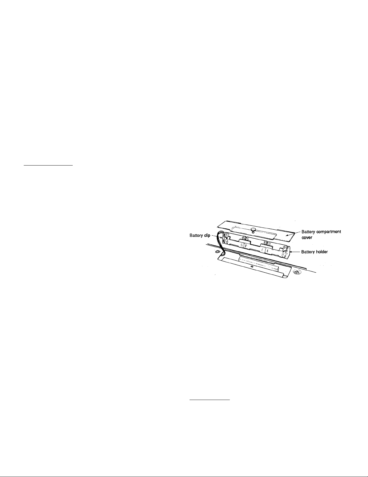
® Use a coin or similar object to turn the large saew retaining the
battery compartment cover on the bottom panel of the MFC06,
and remove the battery compartment cover.
(D Remove the battery holder, taking care not to pull on or damage
the battery wires. Unsnap the battery holder from the battery clip.
0 Install the six batteries in the battery holder, making sure that
each battery faces in the proper direction. Battery orientation
markings are provided on the battery hoider.
0 Snap the battery clip securely back onto the battery holder, and
replace the battery holder in the battery compartment.
0 Replace the battery compartment cover and tighten the retaining
screw.
' When the batteries need replacing, the MFC06 indicators will begin
to flash. When this happens, replace all six batteries at the same
time. New batteries should never be mixed with old ones.
' When performing, it's a good idea to have a spare set of batteries
handy— just in case.
' It is a good idea to have a fresh set of batteries installed even when
using the PA-1 AC adapter. If the AC adapter cord is accidentally
unplugged during use, the MFC06 will instantly switch to battery
power.
' Even when no batteries are installed, make sure to attach the
battery clip to the battery holder. If this is not done, the battery clip
can come in contact with a conducting surface inside the battery
compartment, thus shorting the power supply and possible causing
damage.
SETTING UP___________________________
Please set up the MFC06 according to the following procedure.
0 Install the batteries as described in the previous section, or
connect a Yamaha PA-1 or PA-1 B AC Adapter to the DC 9-12VIN
jack. If batteries are installed and the AC adapter cable is
connected to the MFC06, the batteries are automatically
disconnected and the AC adapter provides power to the MFC06.
Page 2
© After making sure that both the MFC06 power switch and the
FX500 power switch are OFF, connect an appropriate MIDI cable
(less than 15 meters) from the MFC06 MIDI OUT connector to the
MIDI IN connector on the FX500.
© First turn the MFC06 power switch ON, and then the power switch
of the FX500. When the MFC06 power switch is turned ON, the
"PGM" LED indicator will light.
______
)o
1—J
1
t
n I®
1__f 1—1 ' 1
__________
YAMAHA
____________
___________
1 1
_______
1
1
1
f \
@
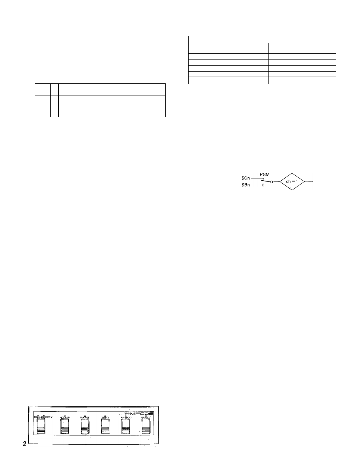
® Set the receive channel of the FX500 "BANK" (A, B, C or D) you
intend to use to "1" or "OMNI." Refer to your FX500 operation
manual for details. The MFC06 transmits only on channel 1.
© Since the MFC06 transmits MIDI program change numbers 1
through 5, make sure the FX500 program change assignment
table for the selected BANK is set up so that these program
numbers select the desired FX500 effect programs.
If, for example, you want the 5 MFC06 footswitches to select
FX500 programs 61 through 65, the FX500 program change
assignment table for the BANK to be used should be set up as
follows:
BANK A,B,CorD.
ch = 1 or OMNI
PGM 1 = MEN 61
PGM 2 = MEM 62
PGM 3 = MEM 63
PGM 4 = MEM 64
PGM 5 = MEM 65
PGM/EFFECT MODE SWITCH
SELECT
SWITCH
1/COMP
2/DIST
3/EQ
4/MOD
5/REV
NOTE: The MFC06 actually transmits MIDI program change numbers
NOTE: No MIDI data is transmitted when the PGM/EFFECT
PGM NO. 1 TRANSMITTED COMPRESSOR STAGE ON/OFF
PGM NO. 2 TRANSMITTED DISTORTION STAGE ON/OFF
PGM N0.3 TRANSMITTED EQUALIZER STAGE ON/OFF
PGM NO. 4 TRANSMITTED MODULATION STAGE ON/OFF
PGM NO. 5 TRANSMITTED
0 through 4, but these correspond to FX500 PGM numbers 1
through 5.
footswitch is pressed. The appropriate MIDI message is
transmitted only when one of the selector footswitches
(1/COMP — 5/REV) is pressed.
PGM EFFECT
REVERB STAGE ON/OFF
MIDI DATA FORMAT
1. TRANSMISSION CONDITIONS
PROGRAM CHANGE
CONTROL CHANGE
2. TRANSMISSION DATA
Channel Information (Channel Voice Message)
PROGRAM CHANGE
STATUS
PROGRAM NO.
STATUS
CONTROL NO.
CTRL VALUE
1 10 0 0 0 0 0 (COH)
OOOOpppp p = 0(PGM1)- -4 (PGM no. 5)
1 01 1 0000 (BOH)
Occccccc c= 116 (COMP) —120 (REV)
Ovvvvvvv v= 0 (OFF), 127 (ON)
EFFECT
MIDI OUT
OPERATION
PGM/EFFECT Footswitch & Indicators
The PGM/EFFECT footswitch determines whether the five selector
footswitches (1/COMP — 5/REV) will transmit MIDI program change
numbers 1 through 5, thereby selecting the corresponding FX500
programs (PGM), or whether the footswitches will turn the corresponding
FX500 effect stages ON and OFF (EFFECT). The "PGM" or "EFFECT"
indicator will light to show which function is currently selected.
PGM MODE: 1/COMP — 5/REV Selector Footswitches & Indicators
When the PGM mode is selected (i.e. the PGM/EFFECT footswitch
"PGM" indicator is lit), footswitches 1/COMP through 5/REV cause
transmission of the corresponding program change numbers. The LED
indicator above the most recently pressed footswitch lights to show which
program number was selected.
EFFECT MODE: 1/COMP — 5/REV Selector Footswitches
When the EFFECT mode is selected (i.e. the PGM/EFFECT footswitch
"EFFECT" indicator is lit), footswitches 1/COMP through 5/REV cause
the corresponding FX500 effect stage to be turned ON or OFF, depending
on its current corxfition. If the selected stage is ON, pressing the
corresponding footswitch will turn it OFF, and vice-versa. The selector
footswitch indicators do not light when the EFFECT models selected.
SPECIFICATIONS
Transmitted Data
MIDI Transmit Channel
Indicators
Switches
Connectors
Power Source AA dry battery x 6, or PA-1(B) AC adapter.
Battery Life
Dimensions 444 mm X 41 mm X130 mm
(WxHxD)
Weight
Supplied Accessories
Optional Accessories
This product is supported by Yamaha's worldwide network of factory trained
and qualified dealer service personnel.
In the event of a problem, contact your nearest Yamaha dealer.
PGM MODE: MIDI program change messages 0
(PGM 1) through 4 (PGM 5).
EFFECT MODE; MIDI control change messages
116(COMP) through 120 (REV).
Channel 1 only.
PGM, EFFECT, 1/COMP, 2/DIST, 3/EQ, 4/MOD,
5/REV.
PGM/EFFECT, 1/COMP, 2/DIST, 3/EQ, 4/MOD,
5/REV, POWER.
MIDI OUT, DC9V—12V IN.
Approximately 10 hours continuous
(alkaline batteries).
(17-1/2" X 1-5/8" X 5-1/8")
1.2 kg. (2.6 lbs.) Incl. batteries.
One set of six AA batteries.
PA-1 or PA-1 B AC Adapter.
SERVICE
Page 3
YAM AH A
COMMANDE AU PIED MIDI MFC06 IVIII
MANUEL D'UTILISATION
Félicitations !
Vous possédez à présent la commande au pied MIDI MFC06 YAMAHA. LE
MFC06 YAMAHA commande au pied te PROCESSEUR MULTI-EFFETS
FXSOO YAMAHA et permet la sélection directe d'un maximum de 5
programmes d'effets différents et un commutateur ON/OFFpour
COMPRESSOR, DISTORTION, EQ, MODULATION et REVERB. Conçu
selon les normes de solidité et de qualité chères à Yamaha, le MFC06 vous
fournira de précieux services pendant de nombreuses années si vous
l'utilisez correctement.
Veuillez lire attentivement ce manuel avant d'installer et d'utiliser votre
MFC06.
PRECAUTIONS___________________________________
1. EVITEZ TOUT EXCES DE CHALEUR, DE POUSSIERE ET DE
VIBRATION
Evitez de placer votre appareil dans des endroits où les
températures ou le taux d'humidité sont trop élevés - près de
radiateurs, etc. Evitez également les endroits où l'instrument risque
d'être soumis à des vibrations, ou une poussière excessive. Ces
conditions pourraient avoir un effet négatif sur les mécanismes de
l'appareil.
2. EVITEZ LES CHOCS
Tout choc excessif peut endommager l'appareil. Manipulez-le avec
soin.
3. N'ESSAYEZ PAS D'OUVRIR L'APPAREIL OU DE LE REPARER
VOUS-MEME.
Cet appareil ne contient aucune pièce que vous pourriez réparer
vous-même. Confier tout entretien à un représentant Yamaha
qualifié. Toute tentative d'ouvrir un appareil ou de manipuler les
drcuits internes vous fera perdre le bénéfice de la garantie.
4. MANIPULEZ LES CABLES AVEC PRUDENCE
N'effectuez vos branchements (et débranchements) qu'en tirant sur
la fiche et non pas sur le câble.
5. NETTOYEZ L'APPAREIL AVEC UN CHIFFON SEC
N'utilisez jamais de solvants, tels qu'essence ou diluant pour
nettoyer vos appareils. Passez seulement un chiffon doux et sec.
6. VEILLEZ A UTILISER LA TENSION CORRECTE
Le MFC06 fonctionne sur piles ou avec un adaptateur CA en
option. Utilisez SEULEMENT l'adaptateur CA PA-1 OU PA-1B
Yamaha lorsque vous branchez votre MFC06 sur le secteur.
L'emploi d'autres adaptateurs CA pourrait entraîner de sérieux
dommages.
7. INTERFERENCES
Les circuits numériques du MFC06 peuvent entraîner des
interférences et des parasites si l'appareil se trouve à proximité de
télévisions, radios ou autre matériel de ce genre. S'il y a
interférence, éloignez le MFC06.
8. SI VOUS N'UTILISEZ PAS L'APPAREIL PENDANT UNE PERIODE
PROLONGEE
Si vous n'utilisez pas l'appareil pendant une période prolongée,
ôtez les piles. Débranchez l'adaptateur de la prise CA même si
vous n'utilisez pas le MFC06.
9. CABLE MIDI
Utilisez toujours le MFC06 avec le câble MIDI approprié. N'utilisez
jamais un câble de plus de 15 mètres.
__
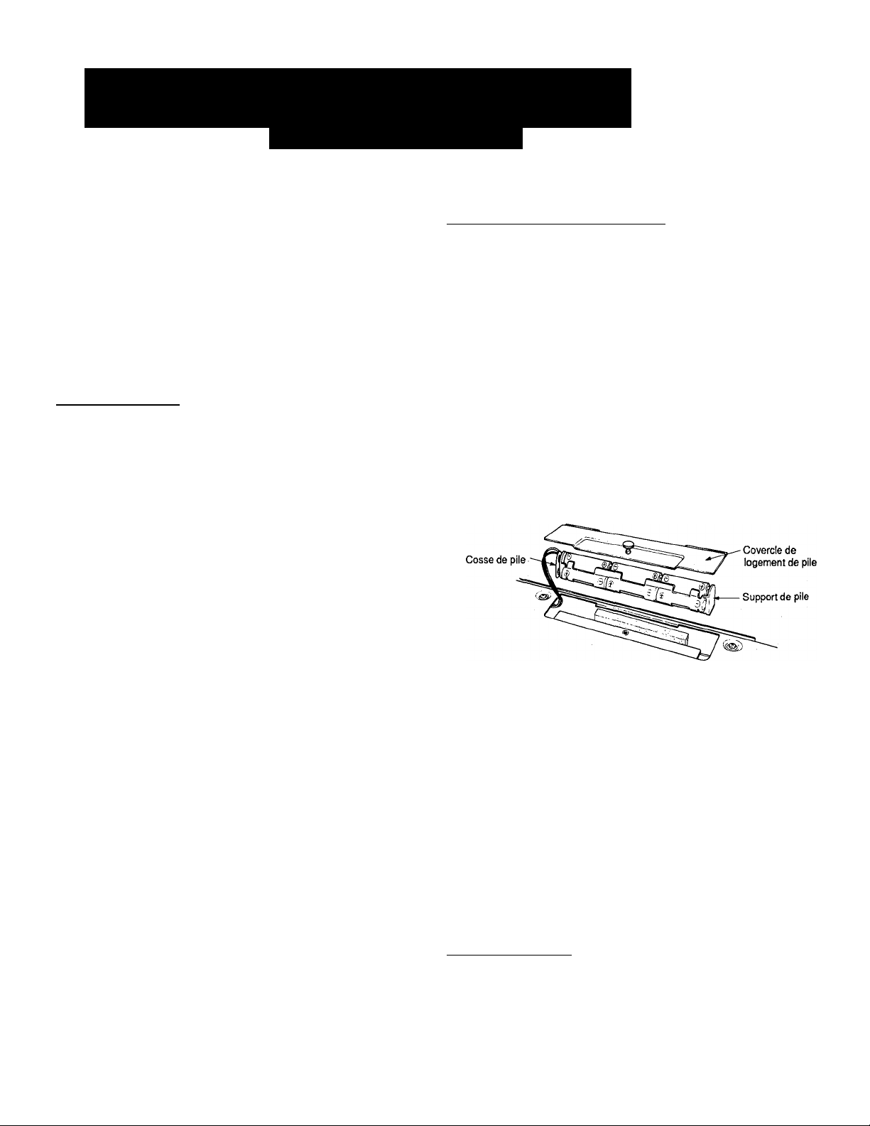
INSTALLATION DES PILES
Le MFC06 requiert 6 piles “AA" si vous avez l'intention de le faire
fonctionner sans l'adaptateur CA PA-1 ou PA-1 B. Les piles alcalines
sont recommandées pour leur durée de vie plus longue.
0 Assurez-vous que l'interrupteur d'alimentation du MFC06 est mis
sur OFF.
0 Utilisez une pièce de monnaie du un objet semblable pour retirer
la vis retenant le couvercle du logement des piles situé sous le
dessous du MFC06. Otez ensuite le couvercle.
0 Relevez le support des piles en veillant à ne pas tirer sur les fils ni
les endommager.
Libérez le support de l'agrafe.
0 Installez les six piles dans le support en veillant à placer chacune
d'entre elle dans le sens indiqué sur le support.
0 Bloquez l'agrafe sur le support et remettez celui-ci dans le
logement.
0 Replacez le couvercle du logement et resserrez la vis.
' Lorsque le remplacement des piles s'avère nécessaire, les témoins
du MFC06 commencent à clignoter. A ce moment-là, remplacez les
six piles en même temps.
' Ne combinez jamais de nouvelles piles avec des anciennes.
Il est utile de posséder un second jeu de piles de rechange pour la
réalisation de vos enregistrements.
Il peut s'avérer judicieux d'installer de nouvelles piles lorsque vous
utilisez l'adaptateur CA PA-1. Si le cordon de l'adaptateur se
débranche par accident, les piles assureront automatiquement
l'alimentation du MFC06.
' Même lorsqu'aucune pile n'est installée, veillez à bloquer l'agrafe
sur le support. Si vous ne le faites pas, l'agrafe entrera en contact
avec une surface conductrice à l'intérieur du logement, ce qui
provoquera un court-circuit et entraînera d'éventuels dommages.
_________________________
INSTALLATION ________________________________________
Veuillez monter le MFC06 en observant la procédure suivante.
0 Installez les piles de la manière décrite dans la section précédente
ou branchez un adaptateur CA PA-1 OU PA-1 B Yamaha à la prise
DC-9V IN. Si les piles sont installées et que le câble de l'adaptateur
est branché au MFC06, l'alimentation cessera d'être fournie par les
piles et sera prise en charge par l'adaptateur.
_
Page 4

Après vous être assuré que les interrupteurs d'alimentation du MFC06 et
@
du FX500 sont sur la position OFF, branchez un câble MIDI approprié
(moins de 15 mètres) entre le connecteur MIDI OUT du MFC06 et le
connecteur MIDI IN du FX500.
Mettez ensuite respectivement l'interrupteur d'alimentation du MFC06 et
finterrupteur d'alimentation du FX500 sur la position ON. Lorsque le
MFC06 est mis sous tension, le témoin LED "PGM" s'allumera.
__________
)o
1
C
ш ||®
г S“"”“
uJj
Réglez le canal de réception du BANK (A, B, C ou D) que vous souhaitez
utiliser sur "1" ou "OMNI". Pour plus de détails, veuillez vous référer au
manuel d'utilisation du FX500. Le MFC06 ne transmet que sur le canal 1.
Comme le MFC06 transmet les numéros de changement de programmes
MID11 à 5, assurez-vous que la table d'assignation de changement de
programme FX500 pour le BANK sélectionné est configurée de telle
façon que ces numéros de programme sélectionnent les programmes
d'effet du FX500 souhaités.
Si, par exemple, vous souhaitez que les 5 commandes au pied du
MFC06 sélectionnent les programmes 61 à 65 du FX500, la table
d'assignation de changement de programme pour le BANK qui sera
utilisé, devra être configurée de la manière suivante:
YAMAHA
1
___
1 U—J
....................—\_________f--------------\____
_________________
_________________
BANK A, B, C ou D
' '''
1
\
1
f \
ch = 1 or OMNI
PGM 1 = MEN 61
PGM 2 = MEM 62
PGM 3 = MEM 63
PGM4 = MEM64
PGM 5 = MEM 65
FONCTIONNEMENT
Commutateur au pied et témoins PGM/EFFECT
Le commutateur au pied PGM/EFFECT détermine si les 5 commandes au
pied (1/COMP - 5/REV) assureront la transmission des numéros de
changement de programme 1 à 5, choisissant de cette façon les
programmes du FX500 (PGM) ou si elles au pied activeront ou désactiveront
les effets du FX500 correspondants. Le témoin "PGM" ou "EFFECr
s'allumera pour indiquer la fonction sélectionnée.
PGM MODE: Commutateurs au pied de sélection et témoins 1/COMP -
5/REV
Lorsque le mode PGM est sélectionné, c'est-à-dire lorsque le témoin "PGM"
du commutateur au pied PGM/EFFECT est éclairé, les commutateurs au
pied 1/COMP à 5/REV entraînent la transmission des numéros de
changement de programme correspondants. Le témoin LED situé au-dessus
du commutateur au pied qui a été actbnné en dernier lieu s'allume pour
indiquer les numéros de programme sélectionnés.
EFFECT MODE: Commutateurs au pied de sélection 1/COMP- 5/REV
Lorsque le mode EFFECT est sélectionné, c'est-à-dire lorsque le témoin
"EFFECT" du commutateur au pied PGM/EFFECT est éclairé, les
commutateurs au pied 1/COMP à 5/REV permettent, en fonction de la
position déterminée, d'activer (ON) ou de désactiver (OFF) l'effet du FX500
carespondant. Si la position choisie est ON, le fait d'appuyer sur le
commutateur correspondant permettra de le faire passer en position OFF et
vice-versa. Les témoins des commutateurs au pied de sélection ne s’allument
pas lorsque le mode EFFECT est sélectionné.
COMMUTATEUR PGM/EFFECT MODE
COMMUTATEUR
DE SELECTION
1/COMP
2/DIST
3/EQ
4/MOD PGM№4 TRANSMIS
5/REV
N.B.: Le MFC06 transmet en fait les numéros de changement de
programme MIDI 0 à 4, mais ceux-ci correspondent aux
numéros PGM 1 à 5 du FX500.
N.B.: Aucune donnée MIDI n'est transmise lorsque le commutateur
au pied PGM/EFFECT est actionné. Le message MIDI adéquat
n'est transmis que lorsque l’un des commutateurs au pied de
sélection (1/COMP - 5/REV) est actionné.
PGM EFFECT
PGMN°1 TRANSMIS
COMPRESSOR STAGE ON/OFF
PGM№2 TRANSMIS DISTORTION STAGE ON/OFF
PGM№3 TRANSMIS EQUALIZER STAGE ON/OFF
MODULATION STAGE ON/OFF
PGM№5 TRANSMIS REVERB STAGE ON/OFF
FORMAT DES DONNEES MIDI
1. CONDITIONS DE TRANSMISSION
PROGRAM CHANGE
CONTROL CHANGE
2. DONNEES DE TRANSMISSION
PGM
MIDI OUT
EFFECT
Information du canal (Channel voice message)
CHANGEMENT DE PROGRAMME
STATUT 1 1 000000 (COH)
^DEPROGRAMME OOOOpppp
p = 0(PGM1) —4(PGM№5)
STATUT 1 01 1 0 0 0 0 (ВОН)
№ DE COMMANDE Occccccc
PARAMETRE Ovvvvvvv
c = 116(COMP) —120(REV)
v = 0(OFF), 127(0N)
CARACTERISTIQUES TECHNIQUES
Données transmises
Canal de transmission MIDI
Témoins
Commutateurs
Connecteurs
Alimentation
Autonomie de pile
Dimensions (L x H x P)
Poids
Accessoires fournis
Accessoires en option
Le MFC06 est couvert par le réseau mondial de service après-vente
Yamaha. En cas de problème, contactez le concessionnaire Yamaha le plus
PGM MODE: messages de changement de
programme 0 (PGM 1) à 4 (PGM 5)
EFFECT MODE: messages de changement de
commande MID1116 (COMP) à 120 (REV)
Canal 1 seulement
PGM, EFFECT, 1/COMP, 2/DIST, 3/EQ, 4/MOD,
5/REV,
PGM/EFFECT, 1/COMP, 2/DIST, 3/EQ, 4/MOD,
5/REV, et interrupteur POWER
MIDI OUT, DC9V—12V IN
Pile AA X 6 ou PA-1 (B) adaptateur CA
Environ 10 heures d'affilée (piles alcalines)
444 mm x 41 mm x 130 mm
1,2 kg (piles comprises)
Jeu de 6 piles
Adaptateur CA PA-1 ou PA-1 B
SERVICE APRES-VENTE
Page 5

¡HB
MFC06 MIDI FOOT CONTRC
BEDIENUNGSANLEITUN
Herzlichen Glückwunsch!
Sie sind jetzt Besitzer eines Yamaha MFC06 MIDI Foot Controllers. Der
MFC06 bietet praktische Fußsteuerung des Yamaha FX500 SIMULEFFECT PROCESSOR: Direkte Fußwahl von bis zu 5 verschiedenen
Effektprogrammen und Ein!Aus-Schalten der Stufen COMPRESSOR,
DISTORTION, EQ, MODULATION und REVERB. DerMFCOö erfüllt die
hohen Qualitätsforderungen von Yamaha und garantiert Ihnen bei richtiger
Behandlung viele Jahre zuverlässigen Einsatz.
Bitte lesen Sie diese Bedienungsanleitung sorgfältig durch, bevor Sie den
MFC06 installieren und in Betrieb nehmen.
VORSICHTSMASSNAHMEN
1. VOR STARKER HITZE, FEUCHTIGKEIT, STAUB UND
VIBRATIONEN SCHÜTZEN
Stellen Sie das Gerät nicht an Orten auf, wo es hohen
Temperaturen oder Feuchtigkeit ausgesetzt wird — wie neben
Heizkörpern, Öfen etc. Vermeiden Sie auch Aufstellungsorte mit
viel Staub oder Vibrationen, die zu mechanischen Schäden führen
können.
2. VOR STARKEN STÖSSEN SCHÜTZEN
Starke Stöße gegen das Gerät können Schäden verursachen.
Behandeln Sie es vorsichtig.
3. NICHT VERSÜCHEN, DAS GEHÄÜSE Zü ÖFFNEN ÖDER
REPARATÜREN ODER MODIFIKATIONEN SELBER
VORZÜNEHMEN
Dieses Produkt enthält keine vom Anwender zu wartenden Teiie.
Lassen Sie alle Wartungsmaßnahmen vom Yamaha-Kundendienst
durchführen. Wenn Sie das Gehäuse öffnen und/oder Eingriffe an
der internen Schaltung vornehmen, verfällt die Garantie.
4. VORSICHTIG MIT DEN KABELN UMGEHEN
Beim Einstecken und Herausziehen von Kabeln immer am Stecker
und niemals am Kabel anfassen.
5. MIT EINEM WEICHEN TROCKENEN LAPPEN REINIGEN
Niemals flüchtige Lösungsmittel wie Benzol oder Farbverdünner
zum Reinigen des Geräts ven/venden. Immer nur mit einem
weichen, trockenen Lappen abwischen.
6. IMMER MIT DEM RICHTIGEN BETRIEBSSTROM BETREIBEN
Der MFC06 arbeitet mit Trockenbatterien oder einem getrennt
erhältlichen Netzteil. Verwenden Sie NUR das Yahama-Netzteil PA-
1 oder PA-1B zum Betrieb des MFC06 mit Netzstrom. Verwendung
von anderen Netzteilen kann schwere Schäden verursachen.
7. ELEKTRISCHE STÖRUNGEN
Der MFC06 enthält digitale Schaltungen und kann Störungen
verursachen, wenn er in der Nähe von Fernsehern, Radios oder
anderen Empfangsgeräten betrieben wird. Wenn Störungen
auftreten, stellen Sie den MFC06 weiter von den betroffenen
Geräten entfernt auf.
8. BEI LÄNGERER NICHTBENUTZUNG
Wenn der MFC06 längere Zeit über nicht verwendet werden soll,
nehmen Sie die Batterien heraus. Das Netzteil sollte bei
Nichtgebrauch aus der Steckdose gezogen werden.
9. MIDI-KABEL
Betreiben Sie den MFC06 immer mit einem richtig konstruierten
MIDI-Kabel. Verwenden Sie nie ein MIDI-Kabel von mehr als 15 m
Länge.
EINLEGEN DER BATTERIEN_______________________
Der MFC06 arbeitet unabhängig vom Netzteil PA-1 oder PA-1B mit 6
Trockenbatterien des Formats R6 (Mignonzellen). Alkalibatterien werden
wegen ihrer längeren Lebensdauer empfohlen.
0 Stellen Sie sicher, daß der MFC06 ausgeschaltet ist.
0 Drehen Sie die große Schraube, die den Batteriefachdeckel an der
Unterseite des MFC06 hpit, mit einer Münze oder einem ähnlichen
Gegenstand und nehmen Sie den Batteriefachdeckel ab.
0 Nehmen Sie den Batteriehalter heraus und achten Sie darauf, nicht die
Batteriekabel zu ziehen oder zu beschädigen. Schnappen Sie den
Batteriehalter vom Batterieclip ab.
0 Legen Sie Sie die sechs Batterien in den Batteriehalter ein und achten
Sie dabei auf die richtige Polarität (Ausrichtung von Plus- und
Minuspol). Im Batteriehalter sind dazu Plus- und Minusmarkierungen
vorhanden.
0 Schnappen Sie den Batterieclip wieder fest auf den Batteriehaiter, und
tauschen Sie den Batteriehalter im Batteriefach aus.
0 Setzen Sie den Batteriefachdeckel wieder auf und ziehen Sie die
Halteschraube fest.
* Wenn die Batterien schwach werden, beginnen die Anzeigen des MFC06
zu blinken. Tauschen Sie dann immer alie 6 Batterien gleichzeitig aus.
Mischen Sie nicht alte und neue Batterien.
* Beim Spielen ist es ratsam, einen Satz frischer Batterien parat zu haben
— für alle Fälle.
* Auch bei Betrieb mit Netzteil ist es empfehlenswert, Batterien eingelegt
zu haben. Falls bei Netzbetrieb versehentlich der Stecker aus der
Steckdose gezogen wird, schaltet der MFC06 sofort auf Batteriebetrieb
um.
* Auch wenn keine Batterien eingelegt sind, sollten Sie immer den
Batterieclip am Batteriehalter ansetzen. Wenn das nicht geschieht, kann
sich der Batterieclip lösen und in Kontakt mit der leitenden Oberfläche im
Inneren des Batteriefachs geraten und so die Betriebsstromversorgung
kurzschließen und möglicherweise Schäden verursachen.
AUFSTELLUNG
Stellen Sie den MFC06 auf folgende Weise auf.
0 Legen Sie die Batterien ein, wie im vorherigen Abschnitt beschrieben,
oder schließen Sie ein Netzteil Yamaha PA-1 oder PA-1 B an die
Buchse DC 9-12V IN an. Wenn Batterien eingelegt sind und das
Netzkabel am MFC06 angeschlossen wird, werden die Batterien
automatisch abgetrennt und auf Netzbetrieb umgeschaltet.
_________________________________________
Page 6

(2) Wenn sichergestellt ist, daß der MFC06 und auch der FX500
ausgeschaltet sind, schließen Sie ein geeignetes MIDI-Kabel (kürzer
als 15 m) an der Buchse MIDI OUT des MFC06 und der Buchse MIDI
IN des FX500 an.
(3) Schalten Sie zuerst den MFC06 ein. und danach den FX500. Wenn
der MFC06 eingeschaltet wird, leuchtet, die “PGM-LED auf.
«Iv/IF=C:CDS
S D B
[
1 1®
rS YAMAHA c
jj—1^^^ ^1
Tz:
1
1
--------------^-------------
'
®
0 Stellen Sie den Empfangskanal der “BANK” des FX500 (A, B, C oder
D) ein, die Sie für “1" oder “OMNI” ven/venden wollen. Einzelheiten
ersehen Sie aus der Bedienungsanleitung des FX500. Der MFC06
gibt nur auf Kanal 1 aus.
Da der MFC06 die MIDI-Programmänderungsnummern 1 bis 5
ausgibt, müssen Sie sicherstellen, daß die ProgrammänderungZuweisungstabelle des FX500 für die gewählte BANK so aufgestellt
ist, daß diese Programmnummern die gewünschten
Effektprogramme des FX500 wählen.
Wenn Sie z.B. wollen, daß die 5 Fußschalter des MFC06 die
Programme 61 bis 65 wählen, sollte die Programmänderungstabelle
für den FX500 wie folgt zusammengestellt werden:
BANK A, B.CoderD
ch=1 or OMNI
PGM 1 = MEN 61
PGM 2 = MEM 62
PGM 3 = MEM 63
PGM 4 == MEM 64
PGM 5 = MEM 65
BEDIENUNG
PGM/EFFECT Fußschalter und Anzeigen
Der PGM/EFFECT Fußschalter bestimmt, ob die fünf Wahlschalter
(1/COMP - 5/REV) MIDI-Programmänderungsnummern 1 bis 5
übertragen und damit die entsprechenden Programme des FX500
wählen (PGM) oder ob die Fußschalter die entsprechenden
Effektstufen des FX500 ein- und ausschalten (EFFECT). Die Anzeige
“PGM” oder “EFFECT” leuchtet je nach der gewählten Funktion auf.
PGM MODUS: 1/COMP - 5/REV Wahl-Fußschalter und Anzeigen
Wenn der Modus PGM gewählt ist (z.B. die Anzeige des
PGM/EFFECT Fußschalters “PGM” leuchtet), bewirken die
Fußschalter 1/COMP bis 5/REV Ausgabe der betreffenden
Programmänderungsnummern. Die LED-Anzeige über dem zuletzt
gedrückten Fußschalter leuchtet auf, um zu zeigen, welche
Programmnummer gewählt wurde.
EFFECT MODUS: 1/COMP - 5/REV Wahl-Fußschalter
Wenn der Modus EFFECT gewählt ist (z.B. die Anzeige des
PGM/EFFECT Fußschalters “EFFECT” leuchtet), wird die
entsprechende Effektstufe des FX500 ein- oder ausgeschaltet, je
nach dem momentanen Zustand. Wenn die gewählte Stufe
eingeschaltet ist, wird sie durch Drücken des Fußschalters
ausgeschaltet und umgekehrt. Die Anzeigen des Wahl-Fußschalters
leuchten nicht auf, wenn der EFFECT-Modus gewählt ist.
)o
¿zLi
WAHL
SCHALTER
1/COMP PGM NR. 1 AUSGEGEBEN
2/DIST PGM NR. 2 AUSGEGEBEN
3/EQ PGM NR. 3 AUSGEGEBEN
4/MQD
5/REV PGM NR. 5 AUSGEGEBEN
HINWEIS: Der MFC06 gibt die MIDI-Programmänderungsnummern 0 bis
HINWEIS: Keine MIDI-Daten werden ausgegeben, wenn der
PGM NR. 4 AUSGEGEBEN
4 aus, aber diese entsprechen den PGM-Nummern 1 bis 5
des FX500.
Fußschalter PGM/EFFECT gedrückt wird. Die entsprechende
MIDI-Meldung wird nur dann übertragen, wenn einer der
Wahl-Fußschalter (1/COMP - 5/REV) gedrückt wird.
PGM/EFFECT MODUS-SCHALTER
PGM
COMPRESSOR-STUFE EIN/AUS
DISTORTION-STUFE EIN/AUS
EQUALIZER-STUFE EIN/AUS
MODULATION-STUFE EIN/AUS
REVERB-STUFE EIN/AUS
EFFECT
MIDI-DATENFORMAT
1. ÜBERTRAGUNGSBEDINGUNGEN
PROGRAM CHANGE
CONTROL CHANGE
2. ÜBERTRAGUNGSDATEN
Kanalinfomiation (Kanal-Stimmenmeldung)
PROGRAMMÄNDERUNG
STATUS
PROGRAMM NR
STATUS
STEUER-NR.
STEUER-WERT
1 1 000000 (COH)
OOOOpppp
1 01 1 0 0 0 0 (BOH)
Occccccc
Ovvvvvvv
PGM
MIDI OUT
EFFECT
p = 0(PGM1)—4(PGM5)
c = 116 (COMP) —120 (REV)
v = 0(AUS), 127 (EIN)
TECHNISCHE DATEN
übertragene Daten
MIDI-Übertragungskanal
Anzeigen
Schalter
Anschlüsse
Betriebsstrom
Batterielebensdauer
Abmessungen (BxHxT)
Gewicht
Mitgeliefertes Zubehör
Getrennt erhältliches Zubehör
Dem MFC06 steht das weltweite Yamaha Kundendienstnetz mit qualifizierten
Technikern zur Verfügung. Im Falle einer Störung sofort den Fachhandel in
Ihrer Nähe benachrichtigen.
PGM-MODUS: MIDI-Programmänderung
Meldungen 0 (PGM 1) bis 4 (PGM 5).
EFFECT-MODUS: MIDI-Steueränderung
Meldungen 116 (COMP) bis 120 (REV).
Nur Kanal 1
PGM. EFFECT, 1/COMP, 2/DIST, 3/EQ,
4/MOD, 5/REV
PGM/EFFECT, 1/COMP. 2/DIST, 3/EQ, 4/MOD,
5/REV, POWER
MIDI OUT, DC9V—12V IN
6 Trockenbatterien Format R6 (Mignon),
oder Netzteil PA-1(B)
Ca. 10 Stunden kontinuierlicher Betrieb (Alkali)
444x41 x130 mm
1,2 kg einschl. Batterien
Ein Batteriesatz (6 St.) R6-Batterien
Netzteil PA-1 oder PA-1B
KUNDENDIENST
Page 7

YAMAHA [ MIDI FOOT CONTROLLER ]
Model MFC06 MIDI Implementation Chart
Date : 7/20, 1989
Version : 1.0
Transmi t ted
Func t i on
Bas i c
Channel
Mode
Default
Changed
Def ault
Messages
: 1 : X
: X :
: X : X
: X : X
A1tered
Note : X : x
Number : True voice: ♦»i:*********»};** : x
--------------------------------------------------------------+
Ve1oci ty No te ON : x
Note OFF : X
After
Touch
Key' s
Ch ’ s
Pitch Bender
-----------------------------------------------------------
■ + —
X
X
+ —
: X
: X
: X
: X
+ —
: X
+ —
116 - 120
Control
Recogn i zed
X
Remarks
*1
Change
Prog
Change True #
System Exclusive
System : Song Pos :
: Song Sel :
Common : Tune :
System :Clock :
Real Time :Commands:
Aux :Local ON/OFF :
:A1I Notes OFF:
Mes- :Active Sense :
sages‘.Reset
• +.- • +
0 0-4
X
X
X
X
X
X
X
X
X
X
*
:
-------
: X
;
■ +
---------
: *2
X
X
X
X
X
X
X
X
X
Notes: *1 At EFFECT
mode
♦2 At PGM mode
Mode 1 : OMNI ON, POLY Mode 2
Mode 3 : OMNI OFF, POLY Mode 4
OMNI ON, MONO
OMNI OFF, MONO
Yes
No
■^7
0
X
Page 8

FCC CERTIFICATION (USA)
This equipment generates and uses radio frequency energy and if not
installed and used properly, that is, in strict accordance with the
manufacturer's instructions, may cause interference to radio and television
reception. It has been type tested and found to comply with the limits for a
Class B computing device in accordance with the specifications in Subpart
J of Part 15 of FCC Rules, which are designed to provide reasonable
protection against such interference in a residential installation.
However,there is no guarantee that interference will not occur in a
particular installation. If this equipment does cause interference to radio or
television reception, which can be determined by turning the equipment off
and on, the user is encouraged to try to correct the interference by one or
more of the foliowing measures: .
Reorient the receiving antenna.
Relocate the equipment with respect to the receiver.
Move the equipment away from the receiver.
Plug the equipment into a different AC power outiet sq that it and the
receiver are on different branch circuits.
If necessary, the user should consult the dealer or an experienced
radio/television technician for additional suggestions. The user may find the.
foilowing booklet prepared by the Federal Communications Commission
helpful;
"How to Identify and Resolve Radio-TV Interference Problems".
This booklet Is available from the U.S. Government Printing Office,
Washington. DC 20402, Stock No. 004-000-00345-4.
CANADA
THIS APPARATUS COMPLIES WITH THE "CLASS B" LIMITS FOR
RADIO NOISE EMISSIONS SET OUT IN RADIO INTERFERENCE
REGULATIONS,
CET APPAREIL EST CONFORME AUX NORMES "CLASSE B", POUR
BRUITS RADIOELECTRIQUES, TEL QUE SPECIFIER DANS LE
REGLEMENT SUR LE BROUILLAGE RADIOELECTRIQUE,
Précautions à prendre lors de la manipulation du matériel de sonorisation
Ne pas placer le coffret et les composants dans les lieux suivants:
* Lieux exposés directement au rayonnement solaire,
* Lieux situés au voisinage d'une source de chaleur et pouvant être
soumis à une élévation excessive de température,
* Lieux humides ou poussiéreux,
‘ Lieux soumis à des vibrations excessives.
Ne pas utiliser, pour le nettoyage de l'appareil, de dissolvants ou de
solutions similaires; éviter aussi toute vaporisation d'InsectIcIdes de
type aérosol au voisinage de l'appareil (les dissolvants et les
Insecticides de type aérosol provoquent souvent, en effet, la
décoloration). Nettoyer l'appareil en l'essuyant avec un tissu doux et
sec.
Avant la mise en marche. Il convient de réduire le volume au minimum,
afin d'assurer la protection du matériel branché.
Ne rien placer sur le bloc dissipateur de chaleur. L'effet de dissipation
de chaleur s'en trouverait réduit d'autant et un fonctionnement
défectueux pourrait en résulter.
Ne jamais forcer lors de la manipulation des interrupteurs, des boutons
et des bornes,
La manipulation do l'appareil doit s'effectuer soigneusement.
Toute manipulation brutale - telle que choc contre un objet dur ou
chute à terre - peut avoir une inddenœ fâcheuse sur les performances
du matériel.
Abstenez-vous de modifier ou de restructurer l'appareil, afin d'éviter
tout mauvais fonctionnement ou toute défaillance.
Assurez-vous que les branchements avec les autre éléments sont
correctement effectués, et notez que le courant doit toujours être coupé
avant d'effectuer tout branchement. Si le bloc doit être déplacé,
détachez au préalable tous les conducteurs, afin d'éviter tout dommage
et tout risque de court-circuit.
Bescheinigung des Importeurs
Hiermit wird bescheinigt, daß der / die / das
MIDI Foot Controller Typ : IVIFC06
{Gerät, Typ, Bezeichnung)
in Übereinstimmung mit den Bestimmungen der
VERFÜGUNG 1046/84
(Amtsblattverfügung)
funkentstört ist.
Der Deutschen Bundespost wurde das Inverkehrbringen dieses Gerätes
angezeigt und die Berechtigung zur Überprüfung der Serie auf Einhaltung
der Bestimmungen eingeräumt.
YAMAHA Europa GmbH
Name des Importeurs
_____________________________________________
_____________________
Précautions à prendre lors de la manipulation de l'appareil
fonctionnant sur courant alternatif
• Assurez-vous que la source d'alimentation correspond au voltage
nominal approprié. Ne jamais brancher l'appareil avec une prise ne
possédant pas le voltage nominal approprié,
• Si l'appareil doit rester inutilisé pendant une longue période, il convient
de débrancher la prise d'alimentation,
• Par temps orageux, débrancher immédiatement l'appareil de la source
d'alimentation, afin d'assurer la protection de ce dernier,
• Evitez de toucher l'interrupteur d'alimentation ou de
brancher/débrancher la prise courant alternatif ou la prise entrée/sortie,
avec des mains humides.
Précautions à prendre lors de la manipulation de l'appareil
fonctionnant sur piles
• Si l'appareil doit rester inutilisé pendant une longue période, retirer les
piles et les conserver en lieu sûr, afin d'éviter tout dommage résultant
de fuites,
■ Utilisez l'adaptateur courant alternatif exclusivement conçu pour
l'appareil. Il convient de noter que certains adaptateurs ont une polarité
différente,
• Lors de l'insertion des plies, assurez-vous que ies polarités sont
correctes. Toute erreur risque de provoquer un fonctionnement
défectueux de l'appareil.
Précautions à prendre lors de la manipulation de l'ampll et du
hautparleur doté d'un ampli Incorporé
• Ne pas fournir au haut-parleur une puissance supérieure à celle
admissible,
• Utiliser un haut-parleur dont l'impédance reste à l'intérieur des limites
données par l'ampli.
YAM AH A
YAMAHA CORPORATION
P,0,Box 1, Hamamatsu, Japan
8908 @ Printed in Japan
 Loading...