


ME422STI
ENGINE SERVICE MANUAL
300902-
ME422STI
N60-28197-ZH-11
ENGINE
SERVICE MANUAL
070026
PrintedinJapan
Nov.2005-0.5×1
YAMAHA MOTOR CO., LTD.
(ME422STI)
(E)
Printed on recycled paper
E
NOTICE
This manual has been prepared by Yamaha primarily for use by Yamaha dealers and
their trained mechanics when performing maintenance procedures and repairs to
Yamaha equipment. It has been written to suit the needs of persons who have a
basic understanding of the mechanical and electrical concepts and procedures
inherent in the work, for without such knowledge attempted repairs or service to the
equipment could render it unsafe or unfit for use.
Because Yamaha has a policy of continuously improving its products, models may
differ in detail from the descriptions and illustrations given in this publication. Use
only the latest edition of this manual. Authorized Yamaha dealers are notified
periodically of modifications and significant changes in specifications and
procedures, and these are incorporated in successive editions of this manual.
ME422STI
ENGINE SERVICE MANUAL
© 2005 Yamaha Motor Co., Ltd.
1st Edition, November, 2005
All rights reserved. Any reprinting or
unauthorized use without the written
permission of Yamaha Motor Co., Ltd. is
expressly prohibited.
Printed in Japan

HOW TO USE THIS MANUAL
MANUAL FORMAT
This manual provides the mechanic with descriptions of the operations of disassembly, repair,
assembly and check, each of which is presented in a sequential, step-by-step procedure.
To a ss is t yo u in f in di ng y ou r wa y aro un d th is m an ua l , th e se ct io n ti tl e an d ma jo r he ad in g i s
given at the head of each page.
A table of contents is provided on the first page of each section.
ILLUSTRATIONS
Some illustrations in this manual may differ from the model you have. This is because a procedure described may relate to several models, though only one is illustrated. (The name of the
model described will be mentioned in the description).
To h e lp yo u id en ti f y c om po ne nt s an d un de r st an d th e c or re ct p ro c ed ur es o f d is a ss em bl y an d
assembly, exploded diagrams are provided. Steps in the procedure are numbered: 1), 2), 3).
Parts shown in the illustrations are identified as: 1, 2, 3.
REFERENCES
These have been kept to a minimum. References to other sections of the manual include the
relevant page number.

¡¡
¡¡
¡ WARNING
Failure to follow WARNING instructions
could result in severe injury or death to the marine
vehicle operator, a bystander, or a person checking or repairing the Stern Drive.
CAUTION:
A CAUTION indicates special precautions that must be taken to avoid damage to the Sterm
Drive.
NOTE:
A NOTE provides key information to make procedures easier or clearer.
INPORTANT INFORMATION
In this Service Manual particularly important information is distinguished in the following ways.
⁄ The safety Alert Symbol means ATTENTION! BECOME ALERT! YOUR SAFETY IS INVOLVED!
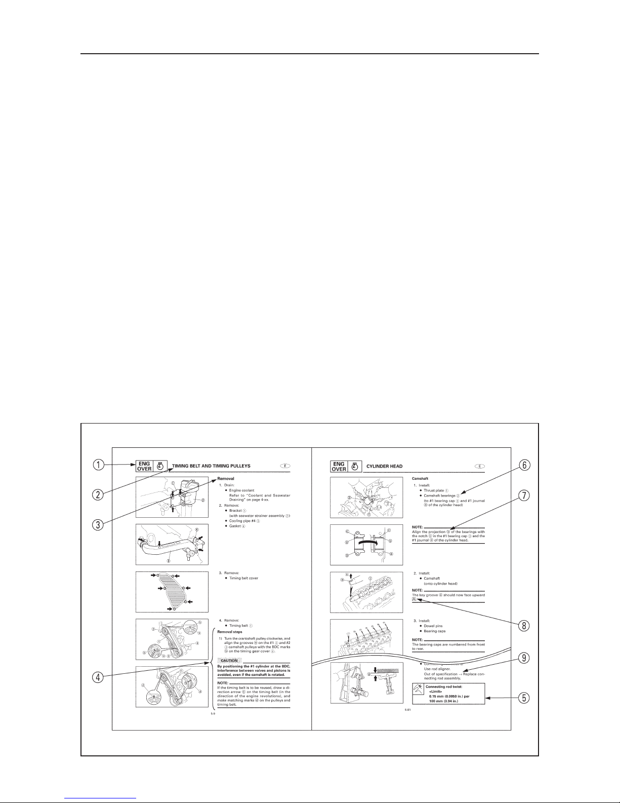
CONSTRUCTION OF THIS MANUAL
This manual consists of chapters for the main categories of subjects. (See “Symbols” on the
next page.)
1st title 1 : This is a chapter with its symbol on the upper right of each page.
2nd title 2 : This title appears on the top of the each page, to the left of the chapter symbol.
3rd title 3 : This title appears only in the chapter “Periodic check and adjustment”.
All the procedures in this manual are organized in a sequential, step-by-step order. The information has been compiled to provide the mechanic with an easy-to-read, handy reference that
contains comprehensive explanations of all disassembly, check, repair, and assembly procedures.
Important procedures including removing, checking, and assembling steps 4 are explained in
detail.
IMPORTANT FEATURES
¡ Important engine data and information about special tools framed in a box together with
an illustrative symbol 5.
¡ A circled numeral 6 indicates a part name. A circled lower case letter indicates data or an
alignment mark 7. Illustrations are sometimes labeled with an upper case letter 8.
¡ An arrow 9 indicates the course of action required to remedy the started condition of a
component.
EXPLODED DIAGRAM
Each chapter begins with exploded diagrams which facilitate correct disassembly and assembly.
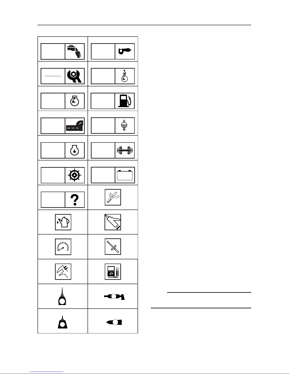
SYMBOLS
Symbols 1 to A are designed as thumb-tabs
and indicate the content of a chapter.
1 General information
2 Specifications
3 Periodic check and adjustment
4 Engine removal and installation
5 Engine
6 Fuel system
7 Exhaust system
8 Cooling system
9 Lubrication system
0 Tur bo ch ar ge r
A Power steering system
B Electrical system
C Tro ub le sh oo ti n g
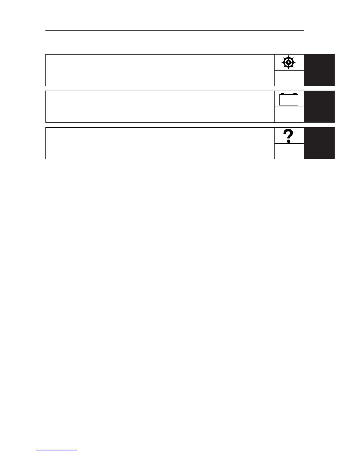
Symbols D to J indicate specific data:
D Special tool
E Recommended fuel
F Lubricant
G Engine speed
H Tighte nin g t orq ue
I Specified value, service, limit
J Resistance (Ω), Voltage (V), Electric cur-
rent (A)
Symbols K and L in an exploded diagram
indicate grade of lubricant and location of
lubrication point:
K Apply Yamaha gear-case lubricant
L Apply water resistant grease (Yamaha
marine grease A, Yamaha marine grease)
Symbols M and N in an exploded diagram
indicate grade of sealing or locking agent,
and location of application point:
M Apply LOCTITE
®
No. 243, 271, 572
N Apply Three Bond
®
TB-1207B, 1322, 1324
NOTE:
Some of the above symbols may not appear
in this manual.
12
34
56
78
90
AB
CD
EF
GH
I
J
K
N
L
M
T.R
A
LT
LT
G
TB
GEN
INFO
SPEC
CHK
ADJ
REM
INST
ENG
OVER
FUEL
EXHT
COOL
LUB TURB
STEER
ELEC
– +
TRBL
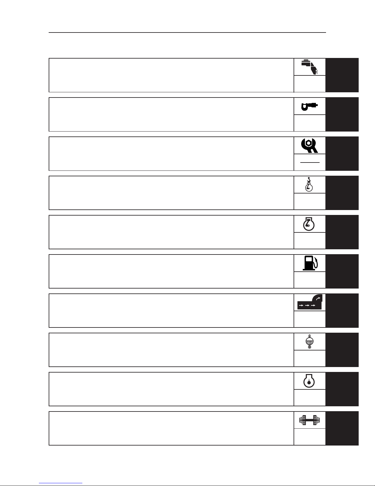
CONTENTS
GENERAL INFORMATION
1
GEN
INFO
SPECIFICATIONS
2SPEC
PERIODIC CHECK AND
ADJUSTMENT
3
CHK
ADJ
ENGINE REMOVAL AND
INSTALLATION
4
REM
INST
ENGINE OVERHAUL
5
ENG
OVER
FUEL SYSTEM
6FUEL
EXHAUST SYSTEM
7EXHT
COOLING SYSTEM
8COOL
LUBRICATION SYSTEM
9
LUB
TURBOCHARGER
10
TURB

INDEX
POWER STEERING SYSTEM
11
STEER
ELECTRICAL SYSTEM
12
ELEC
TROUBLESHOOTING
13
TRBL
SHTG
– +