

Page 1

F50F
FT50G
F60C
FT60D
290551
SERVICE MANUAL
6C1-28197-3G-11
Page 2
NOTICE
This manual has been prepared by Yamaha primarily for use by Yamaha dealers and their trained
mechanics when performing maintenance procedures and repairs to Yamaha equipment. It has
been written to suit the needs of persons who have a basic understanding of the mechanical and
electrical concepts and procedures inherent in the work, for without such knowledge attempted
repairs or service to the equipment could render it unsafe or unfit for use.
Because Yamaha has a policy of continuously improving its products, models may differ in detail
from the descriptions and illustrations given in this publication. Use only the latest edition of this
manual. Authorized Yamaha dealers are notified periodically of modifications and significant
changes in specifications and procedures, and these are incorporated in successive editions of this
manual.
Important information
Particularly important information is distinguished in this manual by the following notations:
The Safety Alert Symbol means ATTENTION! BECOME ALERT! YOUR SAFETY IS
INVOLVED!
WARNING
Failure to follow WARNING instructions could result in severe injury or death to the machine
operator, a bystander, or a person inspecting or repairing the outboard motor.
CAUTION:
A CAUTION indicates special precautions that must be taken to avoid damage to the outboard motor.
NOTE:
A NOTE provides key information to make procedures easier or clearer.
1
F50F, FT50G, F60C, FT60D
SERVICE MANUAL
©2004 by Yamaha Motor Co., Ltd.
1st Edition, July 2004
All rights reserved.
Any reprinting or unauthorized use
without the written permission of
Yamaha Motor Co., Ltd.
is expressly prohibited.
Printed in the Netherlands
Page 3
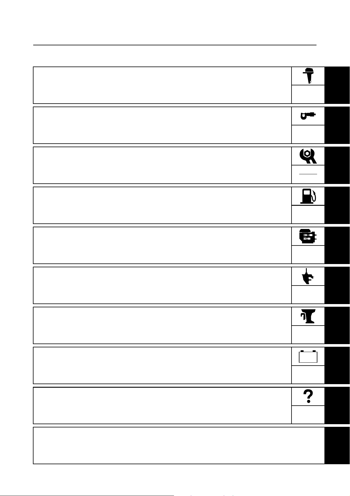
Contents
General information
Specifications
Periodic checks and adjustments
Fuel system
Power unit
GEN
INFO
SPEC
CHK
ADJ
FUEL
POWR
1
2
3
4
5
Lower unit
Bracket unit
Electrical systems
Troubleshooting
Index
LOWR
BRKT
–+
ELEC
TRBL
SHTG
6
7
8
9
Page 4

Page 5

GEN
INFO
General information
How to use this manual.................................................................................1-1
Manual format............................................................................................1-1
Symbols.....................................................................................................1-2
Safety while working......................................................................................1-3
Fire prevention...........................................................................................1-3
Ventilation..................................................................................................1-3
Self-protection ...........................................................................................1-3
Parts, lubricants, and sealants ..................................................................1-3
Good working practices .............................................................................1-4
Disassembly and assembly .......................................................................1-4
1
2
Identification...................................................................................................1-4
Applicable models .....................................................................................1-4
Serial number ............................................................................................1-5
Outline of features .........................................................................................1-6
Features and benefits....................................................................................1-7
Fuel system ...............................................................................................1-7
Solenoid valve ...........................................................................................1-8
Electronic control system...........................................................................1-9
ECM (Electric Control Module) ................................................................1-10
Variable trolling RPM switch (optional)....................................................1-11
Propeller selection.......................................................................................1-12
Propeller size...........................................................................................1-12
Selection..................................................................................................1-12
Predelivery checks ......................................................................................1-13
Checking the fuel system ........................................................................1-13
Checking the engine oil level...................................................................1-13
Checking the gear oil level ......................................................................1-13
Checking the battery................................................................................1-13
Checking the outboard motor mounting height........................................1-14
Checking the remote control cables ........................................................1-14
Checking the steering system .................................................................1-14
Checking the gear shift and throttle operation.........................................1-15
Checking the power trim and tilt system..................................................1-15
Checking the hydro tilt system.................................................................1-15
Checking the engine start switch and engine stop lanyard switch ..........1-16
Checking the cooling water pilot hole ......................................................1-16
Test run ...................................................................................................1-17
Break-in ...................................................................................................1-17
After test run ............................................................................................1-17
3
4
5
6
7
8
9
6C13G11
Page 6
GEN
INFO
General information
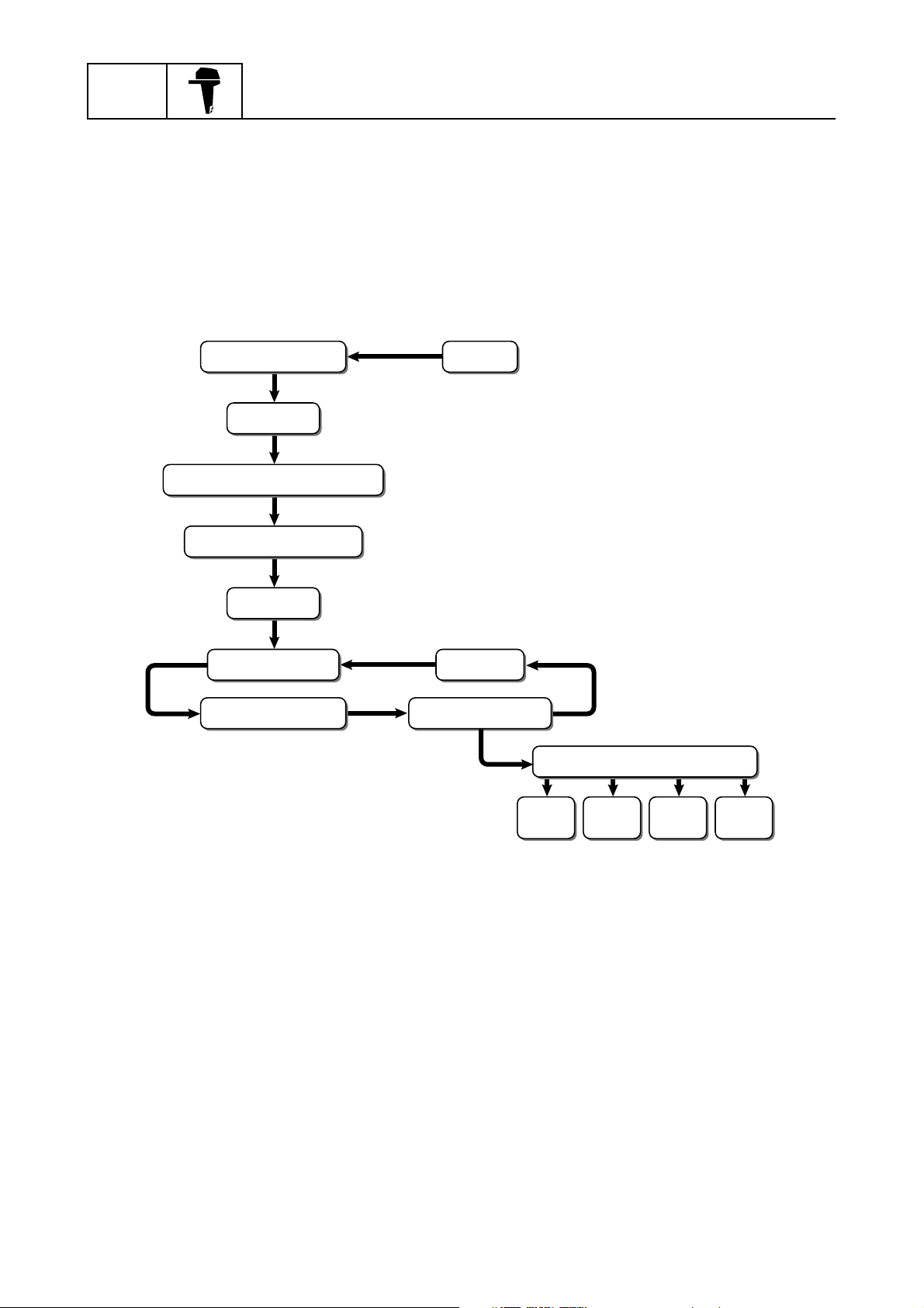
How to use this manual
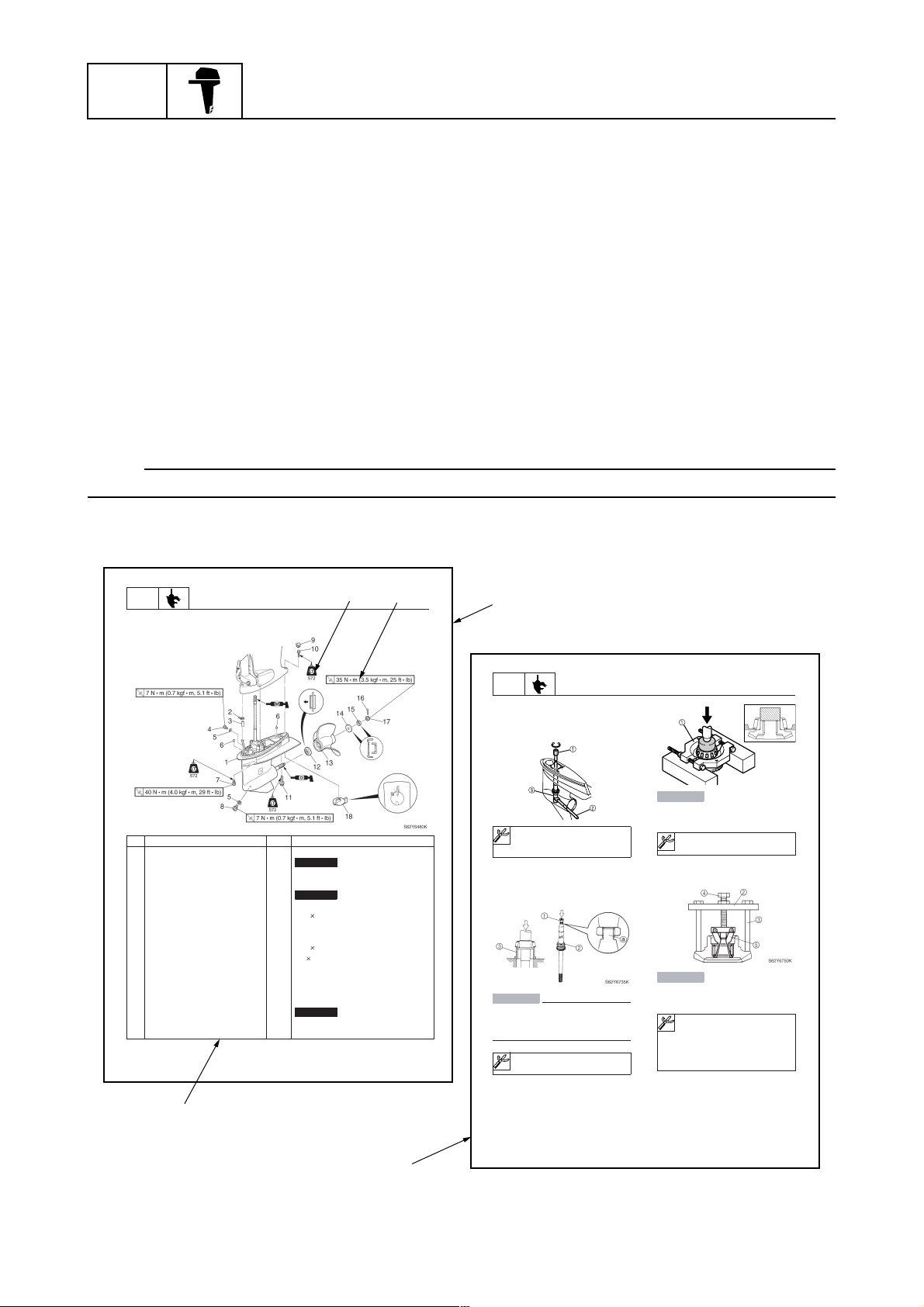
Manual format
The format of this manual has been designed to make service procedures clear and easy to understand. Use the information below as a guide for effective and quality service.
1
Parts are shown and detailed in an exploded diagram and are listed in the components list.
2
Tightening torque specifications are provided in the exploded diagrams and after a numbered
step with tightening instructions.
3
Symbols are used to indicate important aspects of a procedure, such as the grade of lubricant
and lubrication point.
4
The components list consists of part names and part quantities, as well as bolt and screw dimensions.
5
Service points regarding removal, checking, and installation are shown in individual illustrations
to explain the relevant procedure.
NOTE:
For troubleshooting procedures, see Chapter 9, “Troubleshooting.”
1
40 mm
10 45 mm
60 mm
3
LOWR
Lower unit
No. Part name Q’ty Remarks
1 Lower unit 1
2 Plastic tie 1
3Hose 1
4 Check screw 1
5 Gasket 2
6 Dowel pin 2
7 Bolt 4 M10
8 Drain screw 1
9Grommet 1
10 Bolt 1 M
11 Bolt 1 M8
12 Thrust washer 1
13 Propeller 1
14 Washer 1
15 Washer 1
16 Cotter pin 1
17 Propeller nut 1
18 Trim tab 1
6-5
Lower unit
Not reusable
Not reusable
Not reusable
4
2
62Y5A11
1
LOWR
Removing the drive shaft
1. Remove the drive shaft assembly and
pinion, and then pull out the forward
gear.
Disassembling the drive shaft
1. Install the pinion nut 1, tighten it finger
tight, and then remove the drive shaft
bearing 2 using a press.
CAUTION:
• Do not press the drive shaft threads
directly.
• Do not reuse the bearing, always
replace it with a new one.
Disassembling the forward gear
1. Remove the taper roller bearing from the
forward gear using a press.
Lower unit
S62Y6850K
Drive shaft holder 4 1: 90890-06518
Pinion nut holder 2: 90890-06505
Socket adapter 2 3: 90890-06507
Bearing inner race attachment 3:
90890-06639
CAUTION:
Do not reuse the bearing, always replace
it with a new one.
Bearing separator 1: 90890-06534
2. Remove the needle bearing from the forward gear.
CAUTION:
Do not reuse the bearing, always replace
it with a new one.
a
Stopper guide plate 2: 90890-06501
Stopper guide stand 3:
90890-06538
Bearing puller 4: 90890-06535
Bearing puller claw 1 5:
90890-06536
S62Y6740K
1-1
5
6-19
62Y5A11
6C13G11
Page 7
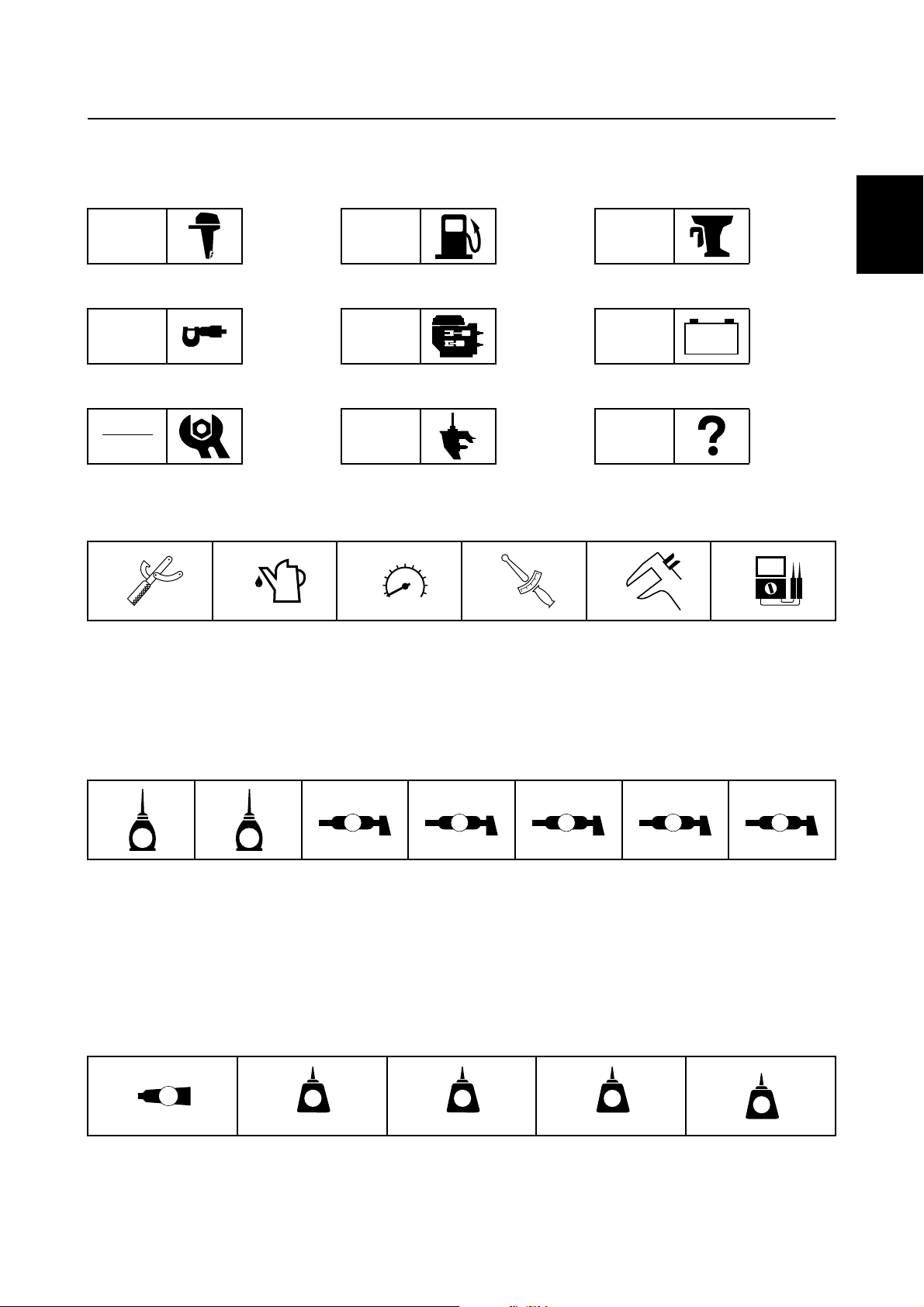
Symbols
T
R
.
.
D
The symbols below are designed to indicate the content of a chapter.
How to use this manual
General information
GEN
INFO
Specifications
SPEC
Periodic checks and adjustments
CHK
ADJ
Symbols 1 to 6 indicate specific data.
123456
Fuel system
FUEL
Power unit
POWR
Lower unit
LOWR
Bracket unit
BRKT
Electrical systems
ELEC
Troubleshooting
–+
TRBL
SHTG
1
2
3
4
Special tool
1
Specified oil or fluid
2
Specified engine speed
3
Specified tightening torque
4
Symbols 7 to C in an exploded diagram indicate the grade of lubricant and the lubrication point.
7890ABC
A M
E G
Apply Yamaha 4-stroke motor oil
7
Apply gear oil
8
Apply water resistant grease (Yamaha grease A)
9
Apply molybdenum disulfide grease
0
Symbols D to H in an exploded diagram indicate the type of sealant or locking agent and the application point.
DEFGH
GM
LT
271
Specified measurement
5
Specified electrical value
6
(resistance, voltage, electric current)
C I
Apply corrosion resistant grease
A
(Yamaha grease D)
Apply low temperature resistant grease
B
(Yamaha grease C)
Apply injector grease
C
LT
242
LT
572
SS
5
6
7
8
9
Apply Gasket Maker
D
Apply LOCTITE 271 (red)
E
Apply LOCTITE 242 (blue)
F
6C13G11
Apply LOCTITE 572
G
Apply silicon sealant
H
1-2
Page 8
GEN
INFO
General information
Safety while working
To prevent an accident or injury and to
ensure quality service, follow the safety procedures provided below.
Fire prevention
Gasoline is highly flammable.
Keep gasoline and all flammable products
away from heat, sparks, and open flames.
Ventilation
Gasoline vapor and exhaust gas are heavier
than air and extremely poisonous. If inhaled
in large quantities they may cause loss of
consciousness and death within a short time.
When test running an engine indoors (e.g., in
a water tank) be sure to do so where adequate ventilation can be maintained.
1
Parts, lubricants, and sealants
Use only genuine Yamaha parts, lubricants,
and sealants or those recommended by
Yamaha, when servicing or repairing the outboard motor.
Under normal conditions, the lubricants mentioned in this manual should not harm or be
hazardous to your skin. However, you should
follow these precautions to minimize any risk
when working with lubricants.
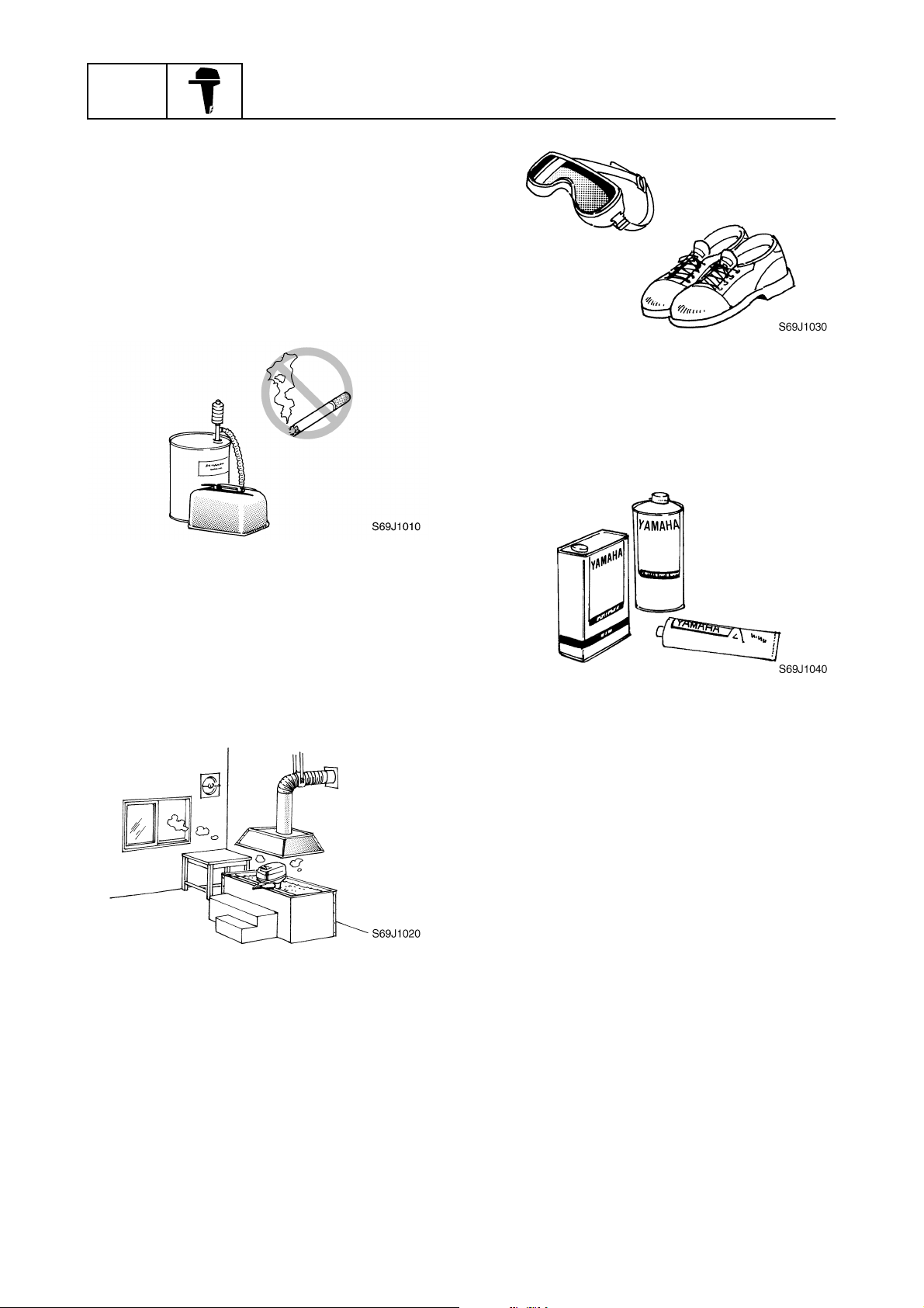
Self-protection
Protect your eyes by wearing safety glasses
or safety goggles during all operations involving drilling and grinding, or when using an air
compressor.
Protect your hands and feet by wearing protective gloves and safety shoes when necessary.
1-3
1. Maintain good standards of personal and
industrial hygiene.
2. Change and wash clothing as soon as
possible if soiled with lubricants.
3. Avoid contact with skin. Do not, for
example, place a soiled rag in your
pocket.
4. Wash hands and any other part of the
body thoroughly with soap and hot water
after contact with a lubricant or lubricant
soiled clothing has been made.
5. To protect your skin, apply a protective
cream to your hands before working on
the outboard motor.
6C13G11
Page 9
6. Keep a supply of clean, lint-free cloths for
wiping up spills, etc.
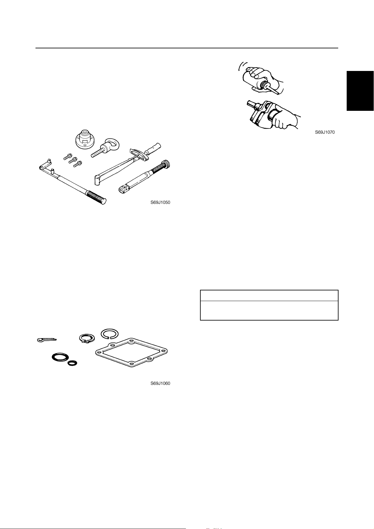
Good working practices
Special service tools
Use the recommended special service tools
to protect parts from damage. Use the right
tool in the right manner—do not improvise.
Tightening torques
Follow the tightening torque specifications
provided throughout the manual. When tightening nuts, bolts, and screws, tighten the
large sizes first, and tighten fasteners starting
in the center and moving outward.
Non-reusable parts
Always use new gaskets, seals, O-rings, cotter pins, circlips, etc., when installing or
assembling parts.
Safety while working / Identification
3. Install bearings with the manufacture
identification mark in the direction indicated in the installation procedure. In
addition, be sure to lubricate the bearings
liberally.
4. Apply a thin coat of water-resistant
grease to the lip and periphery of an oil
seal before installation.
5. Check that moving parts operate normally after assembly.
Identification
Applicable models
This manual covers the following models.
Applicable models
F50FED, F50FEHT, F50FET, FT50GET,
F60CEHT, F60CET, FT60DET
1
2
3
4
1
5
6
Disassembly and assembly
1. Use compressed air to remove dust and
dirt during disassembly.
2. Apply engine oil to the contact surfaces
of moving parts before assembly.
6C13G11
(*)
Hydro tilt model (For Europe)
(*)
Tiller handle model (For Oceania)
7
8
9
1-4
Page 10
GEN
INFO
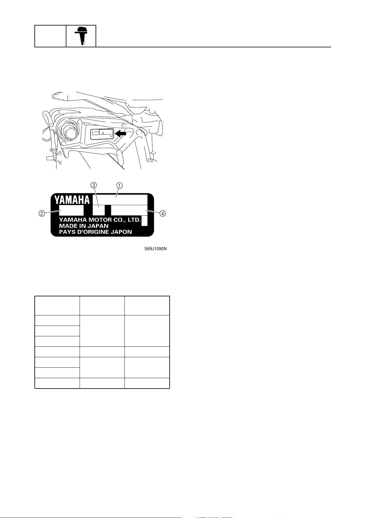
Serial number
The outboard motor serial number is
stamped on a label attached to the port
clamp bracket.
General information
S6C11010
Model name
1
Approved model code
2
Transom height
3
Serial number
4
Model name
Approved
model code
Starting
serial No.
F50FED
6C1 1000001–F50FEHT
F50FET
FT50GET 6C2 1000001–
F60CEHT
6C5 1000001–
F60CET
FT60DET 6C6 1000001–
(*)
Hydro tilt model (For Europe)
(*)
Tiller handle model (For Oceania)
1-5
6C13G11
Page 11
Identification / Outline of features
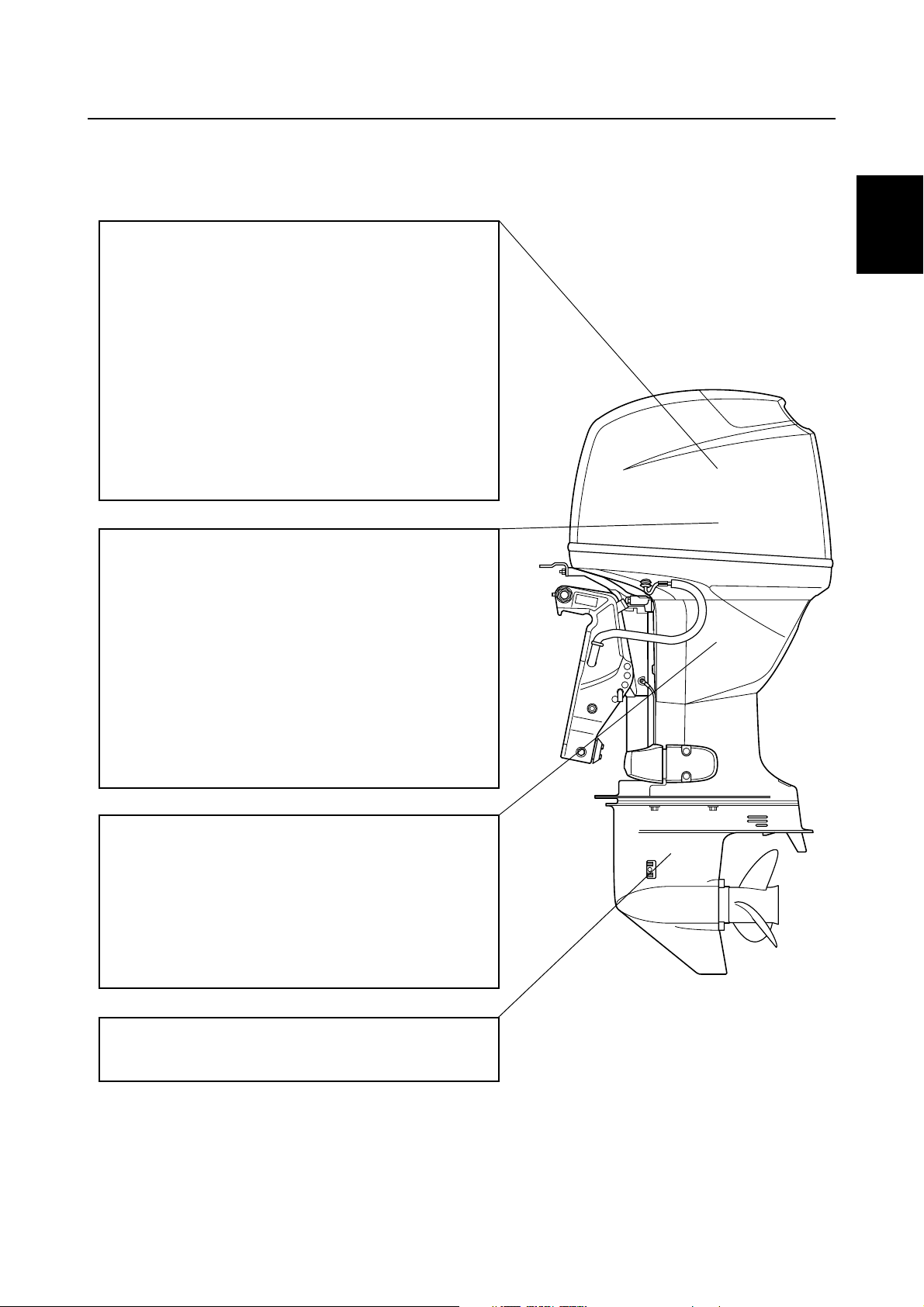
Outline of features
New electronic fuel injected F50 and F60 outboard motors have a mainly redesigned fuel and intake
system based on the carbureted F60 outboard motor.
Power unit
• Single throttle body, single throttle valve
• Multi-point injection system, group injection
(#1/#4 and #2/#3)
• Group ignition system (#1/#4 and #2/#3)
• Large plastic intake manifold
• Compact plastic fuel rail
• Modularized intake system components
• Vapor separator with built-in pressure regulator
• Solenoid valve
• Fuel cooler
• Aluminum rocker arm
Electrical
• Compact electronic fuel injection system
• Self-diagnosis system and Yamaha Diagnostic
System
• Variable trolling RPM switch (optional for tiller
handle model)
• Throttle position sensor with learning function
(adjustment free)
• Compact charging system at low rpm
• Compact fuel injectors
• Fuel filter with water separator
1
1
2
3
4
5
6
Clamp bracket/upper case
• 2-piece upper case
• Upper portion case with oil sump
• Big capacity water wall structure around muffler
• Idle exhaust labyrinth structure
• Exclusive clamp bracket for permanent mount-
ing
Lower unit
• Same lower drive unit as carbureted F60 model
6C13G11
S6C11120
1-6
7
8
9
Page 12
GEN
INFO
General information
Features and benefits
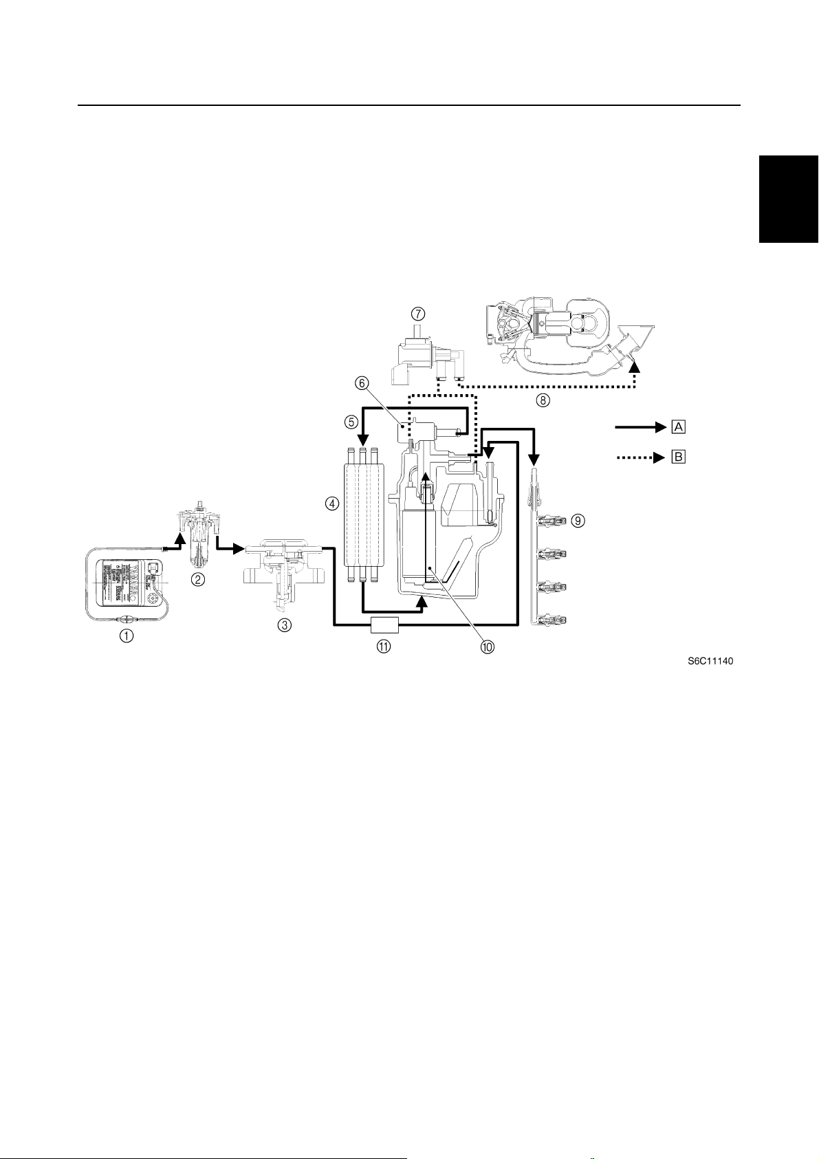
Fuel system
A pressure regulator is built into the vapor separator to obtain compact and simple fuel delivery
structure.
A plastic fuel rail is used to prevent it from corrosion and for light weight.
Fuel discharged from the pressure regulator returns to the vapor separator after cooling down
through the fuel cooler.
The fuel joint is used on the high pressure fuel hose to remove and/or install the intake unit easily.
Fuel filter (Optional) Fuel tank
Primer pump
Fuel filter with water separator
Fuel pump (Mechanical)
1
Fuel filter
Vapor separator
Electric fuel pump
Fuel cooler
Pressure regulator
injector
Fuel
#1
Fuel rail
Fuel
injector
#2 #3 #4
Fuel
injector
Fuel
injector
S6C11130
1-7
6C13G11
Page 13
Features and benefits
Solenoid valve
Just after the engine is stopped, the cooling water supply is also stopped and the heat is conducted
to the vapor separator from the engine, causing birth of many fuel vapor gases.
The vapor gases are fed into the intake silencer to reburn them.
However, many vapor gases are sucked into the combustion chambers, causing a rich air and fuel
mixture, which is difficult to restart the engine.
So the solenoid valve has been used for better restarting engine while the engine is warm.
The solenoid valve stops the vapor gases not to return into the intake silencer.
1
2
3
Fuel tank
1
Fuel filter
2
Fuel pump
3
Fuel cooler
4
Return fuel hose
5
Pressure regulator
6
Solenoid valve
7
To throttle body
8
Fuel injector
9
Electric fuel pump
0
Fuel filter
A
Fuel
È
Vapor gas
É
4
5
6
7
8
6C13G11
9
1-8
Page 14
GEN
INFO
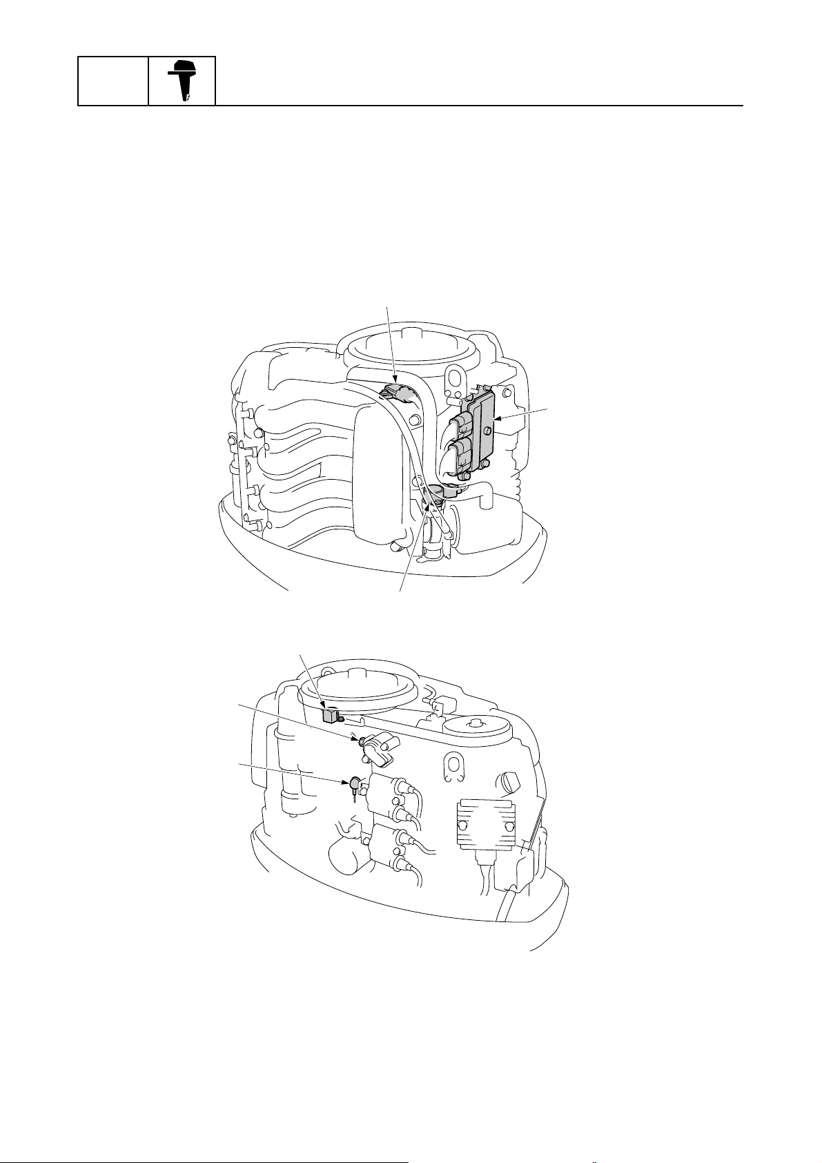
Electronic control system
The electronic control system is built up by the sensors and the ECM (Electric control Module).
The ECM receives signals from the sensors and determines the air and fuel mixture (A/F), and ignition timing.
Under various condition, the ECM gives the best-suitable engine operation.
In addition, warning control, fail-safe control, a self-diagnosis function, etc., are equipped to
increase reliability.
General information
1
2
5
4
Sensor assembly
1
(intake air temperature and intake air
pressure)
ECM
2
Throttle position sensor
3
Oil pressure switch
4
6
3
Cooling water temperature sensor
5
Pulser coil
6
S6C11150
1-9
6C13G11
Page 15
Features and benefits
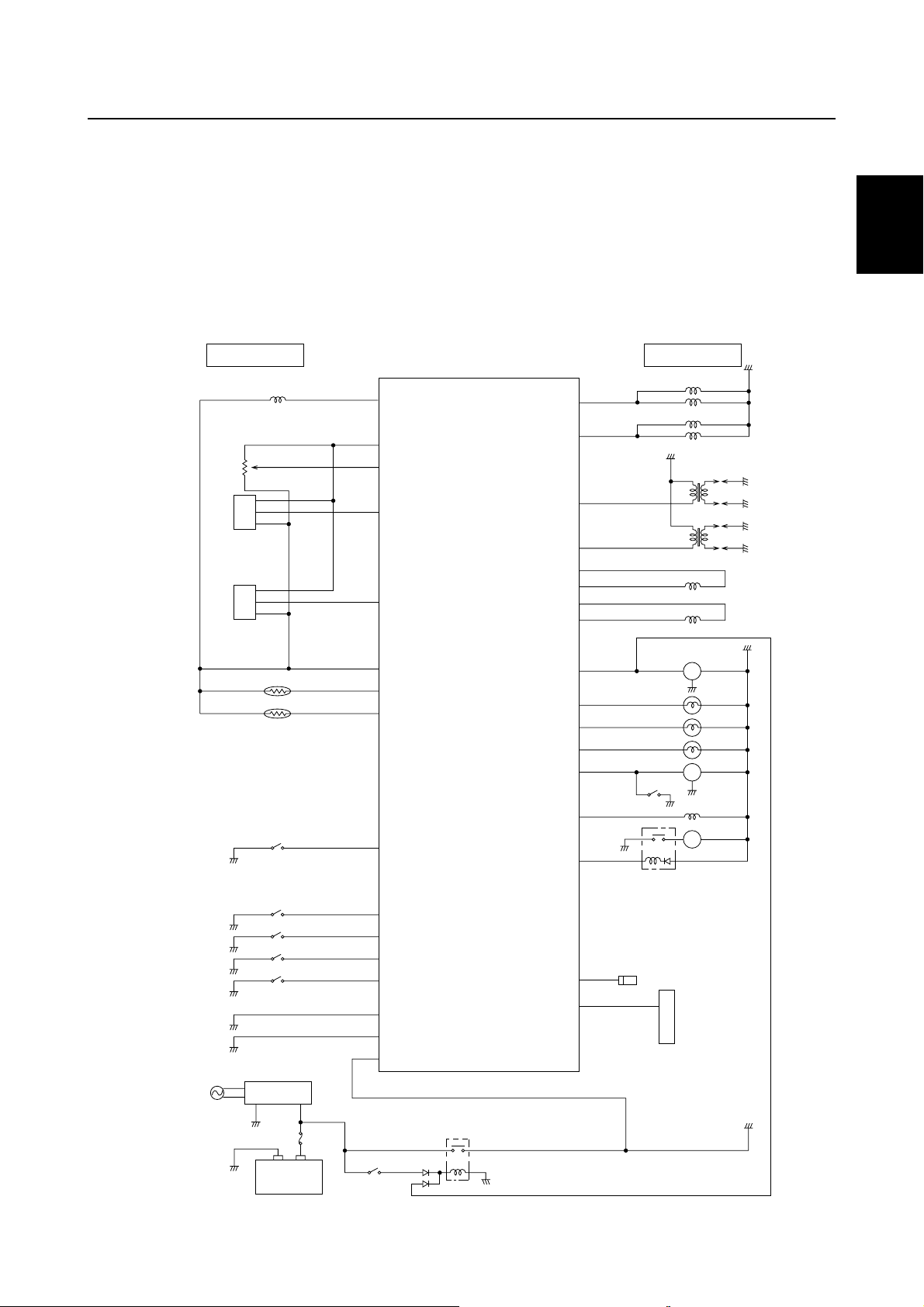
ECM (Electric Control Module)
This engine is controlled by the ECM to obtain precision combustion under various operations, and
can realize high power output, low fuel consumption, and low emission.
The ECM controls the ignition timing, fuel injection timing, and the fuel injection volume, and
ensures that the optimum ignition timing and air and fuel ratio can be achieved in all operating conditions such as engine starting, normal operation, and quick acceleration.
The self-diagnosis function is incorporated into the ECM and can be easily found a malfunction
point by a personal computer with the optional software installed.
1
40
Pulser coil
16
Power source for sensors
36
Throttle position
sensor
17
Intake air pressure
sensor
46
Cooling water pressure sensor
31
Ground for sensors
38
Intake air temperature sensor
48
Cooling water temperature sensor
34
Shift position switch
Fuel injectors #1, #4
Fuel injectors #2, #3
Ignition coil #1, #4
Ignition coil #2, #3
Idle speed control (S1)
Idle speed control (S2)
Idle speed control (S3)
Idle speed control (S4)
Tachometer
Oil pressure warning
indicator
Overheat
warning
indicator
Check engine warning
indicator
Buzzer/DES switch
Solenoid valve
Fuel pump relay
3
4
18
1
23
6
20
21
7
26
8
25
9
DES switch
11
24
OUTPUTINPUT
Main relay
Relay
2
3
4
T
BZ
P
5
6
7
6C13G11
Flywheel
magnet
Rectifier Regulator
– +
Battery
27
Engine stop lanyard switch
10
Oil pressure switch
28
Variable trolling RPM switch (UP)
29
Variable trolling RPM switch
(DOWN)
14
Ground for ECM
5
Ground
15
Battery (+)
Engine start switch
Main relay
Diagnosis
45
13
Power for diagnosis lamp
Self-diagnosis
8
9
S6C11160
1-10
Page 16
GEN
INFO
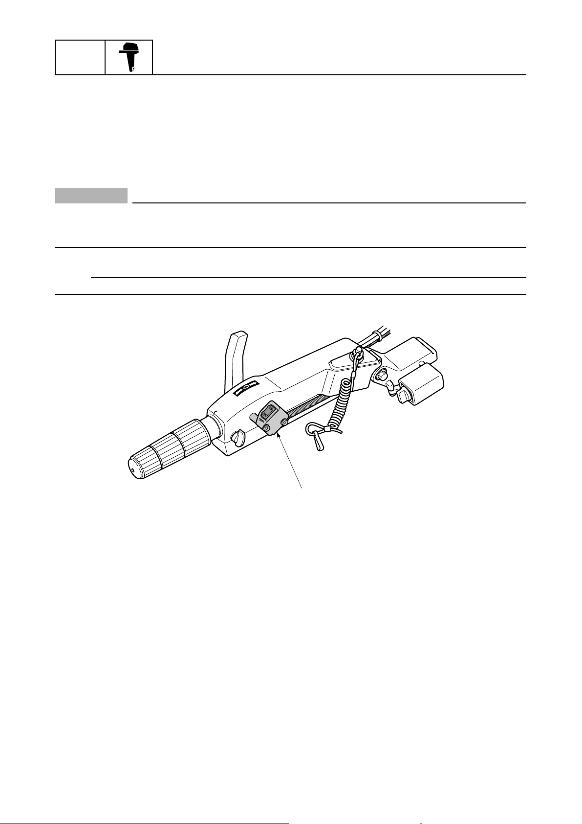
Variable trolling RPM switch (optional)
This device is an optional equipment for tiller handle model.
The idling and/or trolling rpm can be controlled in the range of 620 through 900 r/min with 50 r/min
interval.
Especially for 620 through 700 r/min, the engine rpm is controlled with 40 r/min interval.
Pushing and holding the switch changes rpm continuously at 50 r/min interval.
If engine rpm reaches to the ends of specified range, the rpm is no longer changed.
CAUTION:
Do not modify the variable trolling RPM switch.
Modification such as wire extension, disassembly, etc., can malfunction for the system and/
or damage the electrical components.
NOTE:
Variable trolling RPM switch kit P/N: 6C5-W8186-00
General information
Variable trolling RPM switch (optional)
1
1
S6C11170
1-11
6C13G11
Page 17
Features and benefits / Propeller selection
Propeller selection
The performance of a boat and outboard
motor will be critically affected by the size
and type of propeller you choose. Propellers
greatly affect boat speed, acceleration,
engine life, fuel economy, and even boating
and steering capabilities. An incorrect choice
could adversely affect performance and
could also seriously damage the engine.
Use the following information as a guide for
selecting a propeller that meets the operating
conditions of the boat and the outboard
motor.
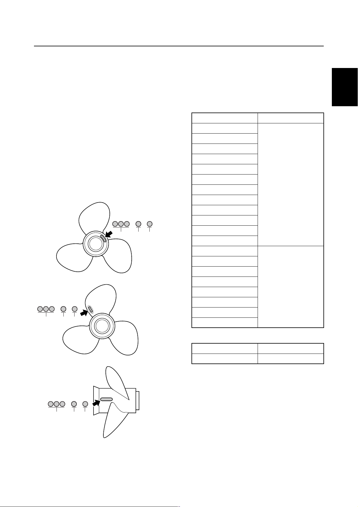
Propeller size
The size of the propeller is indicated on a
propeller blade, on the propeller boss end.
× -
a
bc
1
Selection
When the engine speed is at the full throttle
operating range (5,000–6,000 r/min), the
ideal propeller for the boat is one that provides maximum performance in relation to
boat speed and fuel consumption.
F50, F60
Propeller size (in) Material
10 × 15 - G
10 1/4 × 14 - G
10 3/8 × 13 - G
10 5/8 × 12 - G
10 3/4 × 16 - G
10 3/4 × 17 - G
Aluminum
11 × 15 - G
11 1/8 × 13 - G
11 1/4 × 14 - G
11 3/8 × 12 - G
11 5/8 × 11 - G
12 1/4 × 9 - G
1
2
3
4
× -
a
bc
× -
a
bc
S69W1030
S69W1040
10 1/4 × 14 - G
10 1/4 × 15 - G
10 1/4 × 16 - G
10 5/8 × 13 - G
Stainless
11 1/4 × 14 - G
11 1/2 × 13 - G
11 3/4 × 12 - G
12 × 11 - G
FT50, FT60
Propeller size (in) Material
14 × 11 - K Aluminum
5
6
7
8
9
Propeller diameter (in inches)
a
Propeller pitch (in inches)
b
Propeller type (propeller mark)
c
6C13G11
S69W1050
1-12
Page 18
GEN
INFO
General information
Predelivery checks
To make the delivery process smooth and
efficient, the predelivery checks should be
completed as explained below.
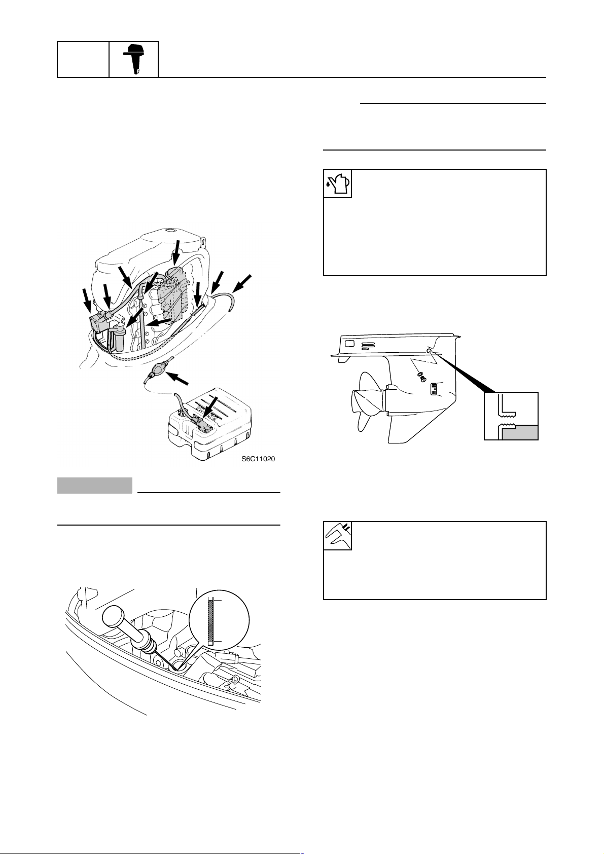
Checking the fuel system
1. Check that the fuel hoses are securely
connected and that the fuel tank is full
with fuel.
1
NOTE:
If the engine oil is below the minimum level
mark b, add sufficient oil until the level is
between a and b.
Recommended engine oil:
4-stroke motor oil
API: SE, SF, SG, SH, or SJ
SAE: 10W-30 or 10W-40
Engine oil quantity:
Without oil filter replacement:
2.5 L (2.64 US qt, 2.20 Imp qt)
Checking the gear oil level
1. Check the gear oil level.
CAUTION:
This is a 4-stroke engine. Never use premixed fuel.
Checking the engine oil level
1. Check the engine oil level.
a
b
S6C11030
S60V1290
Checking the battery
1. Check the capacity, electrolyte level, and
specified gravity of the battery.
Recommended battery capacity:
CCA/EN: 430 A
20HR/IEC: 70 Ah
Electrolyte specified gravity:
1.280 at 20 °C (68 °F)
2. Check that the positive and negative battery leads are securely connected.
1-13
6C13G11
Page 19
Predelivery checks
Checking the outboard motor
mounting height
1. Check that the anti-cavitation plate is
aligned with the bottom of the boat. If the
mounting height is too high, cavitation
will occur and propulsion will be reduced.
Also, the engine speed will increase
abnormally and cause the engine to
overheat. If the mounting height is too
low, water resistance will increase and
reduce engine efficiency.
a
b
d
c
S6C11080
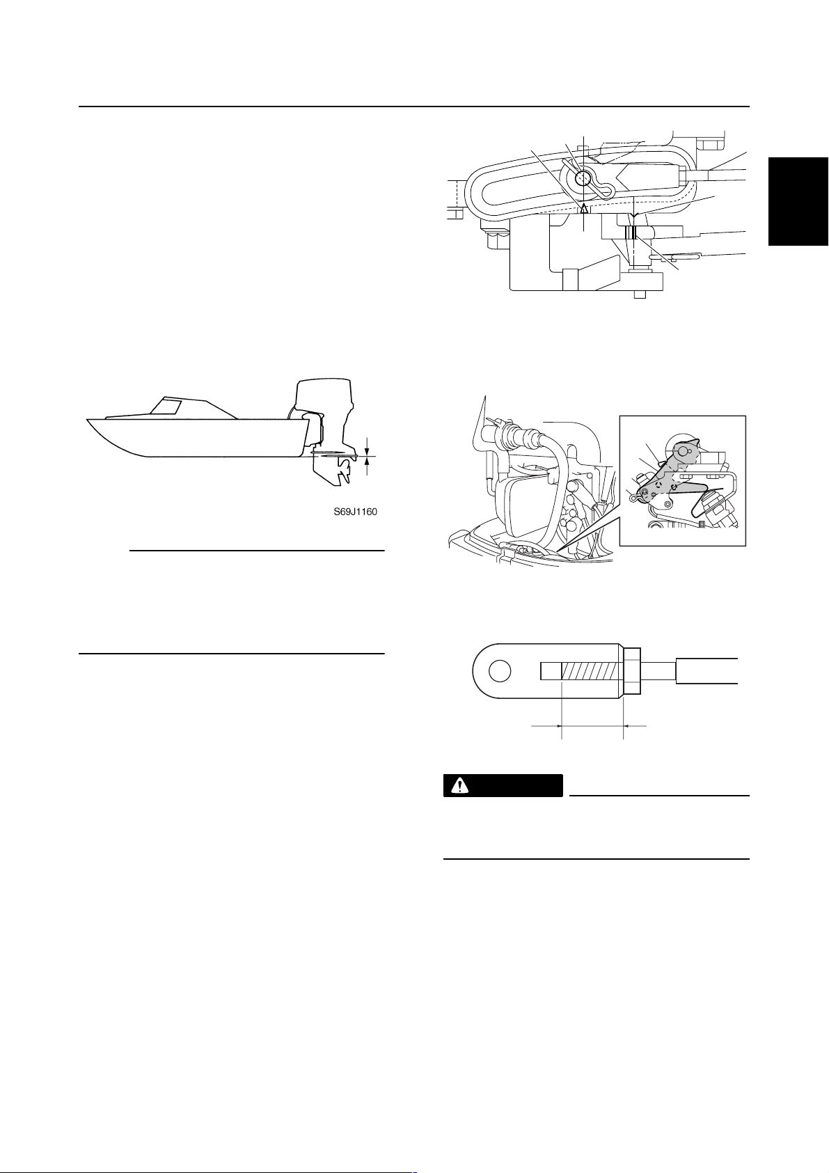
4. Check that the edge of a shift rod e is
aligned with the alignment mark f on
the bottom cowling.
f
e
1
2
3
4
NOTE:
The optimum mounting height is affected by
the combination of the boat and the outboard
motor. To determine the optimum mounting
height, test run the outboard motor at different heights.
2. Check that the clamp brackets are
secured with the clamp bolts.
Checking the remote control cables
1. Set the remote control lever or shift lever
to the neutral position and fully close the
throttle lever or throttle grip.
2. Check that the set pin a is aligned with
the alignment mark b.
3. Check that the alignment mark c is
aligned with the mark d.
S6C11090
g
WARNING
The shift/throttle cable joint must be
screwed in a minimum of 8.0 mm (0.31 in)
.
g
Checking the steering system
1. Check the steering friction for proper
adjustment.
S6C11110
5
6
7
8
6C13G11
9
1-14
Page 20
GEN
INFO
General information
2. Check that the steering operates
smoothly.
È
É
Tiller handle model
È
Remote control model
É
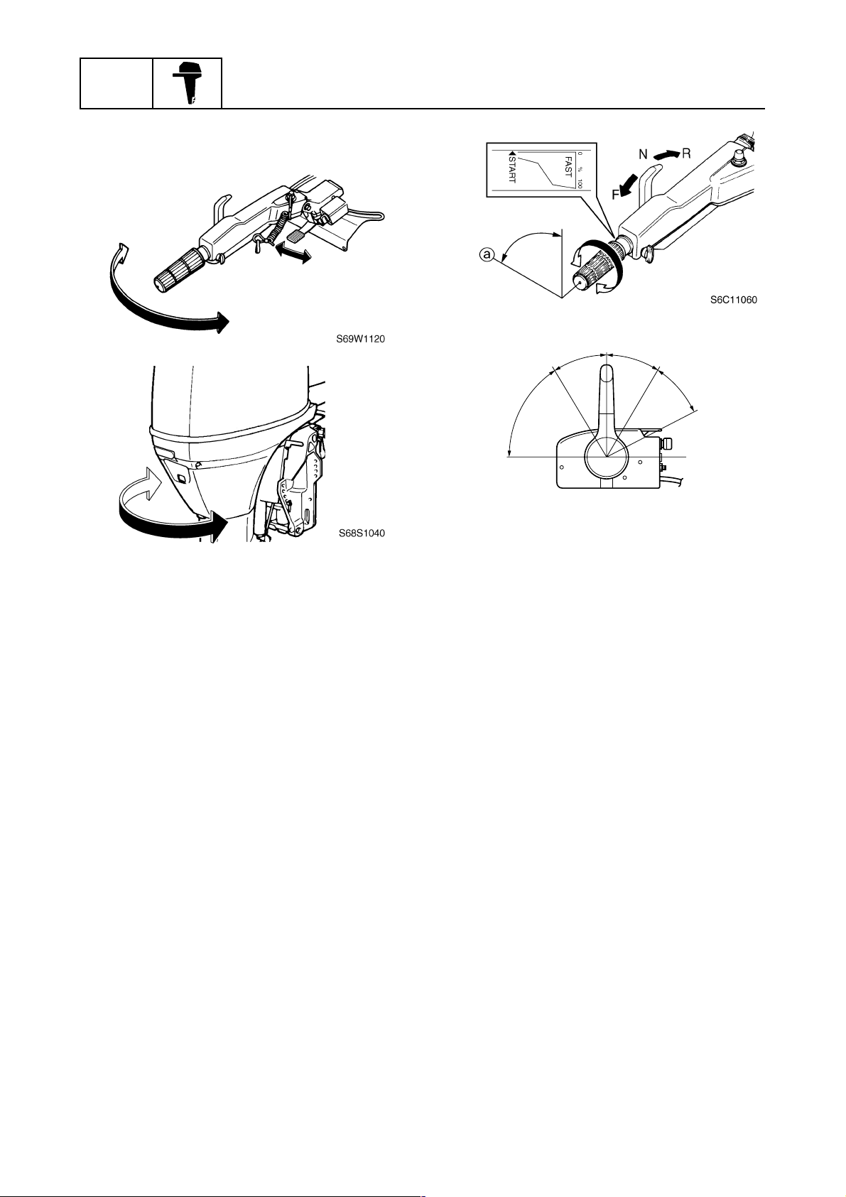
3. Check that there is no interference with
wires or hoses when the outboard motor
is steered.
È
É
N
F
R
a
a
S69J1210
Tiller handle model
È
Remote control model
É
Checking the power trim and tilt
system
1. Check that the outboard motor tilts up
and down smoothly when operating the
power trim and tilt unit.
Checking the gear shift and throttle
operation
1. Check that the gear shift operates
smoothly when the remote control lever
or shift lever is shifted from neutral to forward or reverse.
2. Check that the throttle operates smoothly
when the throttle grip (tiller handle
model) is turned from the fully closed
position to the fully open position a.
Check that the throttle operates smoothly
when the remote control lever (remote
control model) is shifted from forward or
reverse to the fully open position a.
2. Check that there is no abnormal noise
produced when the outboard motor is
tilted up or down.
3. Check that there is no interference with
wires or hoses when the tilted-up outboard motor is steered.
4. Check that the trim meter points down
when the outboard motor is tilted all the
way down.
Checking the hydro tilt system
1. Check that the outboard motor tilts up
and down smoothly.
2. Fully tilt the outboard motor up, and then
lock the tilt stop lever 1 to check the lock
mechanism of the hydro tilt. Replace the
hydro tilt unit if necessary.
1-15
6C13G11
Page 21
Predelivery checks
1
S6C11100
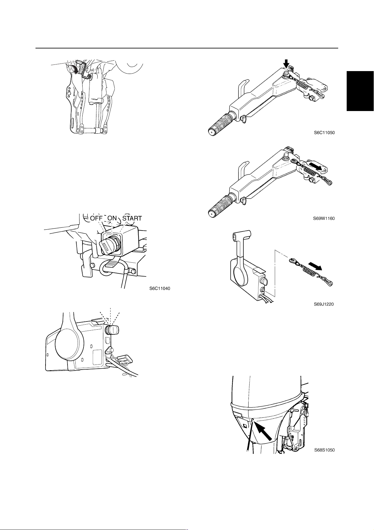
Checking the engine start switch and
engine stop lanyard switch
1. Check that the engine starts when the
engine start switch is turned to START.
2. Check that the engine turns off when the
engine start switch is turned to OFF.
È
È
É
1
2
3
4
É
Tiller handle model
È
Remote control model
É
3. Check that the engine turns off when the
engine stop lanyard switch is pushed or
engine stop lanyard is pulled from the
engine stop lanyard switch.
OFF
ON
START
S60V1070
Tiller handle model
È
Remote control model
É
Checking the cooling water pilot
hole
1. Check that cooling water is discharged
from the cooling water pilot hole.
5
6
7
8
9
6C13G11
1-16
Page 22

GEN
INFO
General information
Test run
1. Start the engine, and then check that the
gear shift operates smoothly.
2. Check the engine idle speed after the
engine has been warmed up.
3. Operate at trolling speed.
4. Run the outboard motor for 1 hour at
2,000 r/min or at half throttle, then for
another hour at 3,000 r/min or at 3/4
throttle.
5. Check that the outboard motor does not
tilt up when shifting into reverse and that
water does not flow in over the transom.
NOTE:
The test run is part of the break-in operation.
After test run
1. Check for water in the gear oil.
2. Check for fuel leakage in the cowling.
3. Flush the cooling water passage with
fresh water using the flushing kit and with
the engine running at idle.
Break-in
During the test run, perform the break-in
operation in the following three stages.
1. One hour a at 2,000 r/min or at approximately half throttle
2. One hour b at 3,000 r/min or 3/4 throttle
and 1 minute out of every 10 at full throttle
3. Eight hours c at any speed, however,
avoid running at full speed for more than
5 minutes
È
ab
0
1
210
c
Hour
È
1-17
S69J1240
6C13G11
Page 23

SPEC
Specifications
General specifications...................................................................................2-1
Maintenance specification ............................................................................2-5
Power unit..................................................................................................2-5
Lower unit ..................................................................................................2-8
Electrical ....................................................................................................2-9
Power unit................................................................................................2-11
Lower unit ................................................................................................2-14
Electrical ..................................................................................................2-15
Dimensions..............................................................................................2-17
Tightening torques.......................................................................................2-21
Specified torques.....................................................................................2-21
General torques.......................................................................................2-24
1
2
3
4
5
6
7
8
9
6C13G11
Page 24
SPEC
Specifications
General specifications
1,339
(52.7)
114.0
(251)
Tiller
Model
706 (27.8)
110.0
(243)
Remote control
Item Unit
F50FED F50FEHT F50FET FT50GET
Dimension
Overall length mm (in) 706
(27.8)
Overall width mm (in) 384 (15.1)
Overall height
(L) mm (in) 1,415 (55.7) 1,455
(*1)
(X)
mm (in) — 1,569
Boat transom height
(L) mm (in) 508 (20.0)
(*1)
(X)
mm (in) — 635
Weight
(with aluminium propeller)
(L) kg (lb) 107.0
(236)
(*1)
(X)
kg (lb) — 119.0
Performance
Maximum output kW (hp) 36.8 (50.0) at 5,500 r/min
Full throttle operating range r/min 5,000–6,000
Maximum fuel consumption L (US gal,
18.5 (4.89, 4.07) at 6,000 r/min
lmp gal)/hr
Engine idle speed r/min 700–800
Power unit
Type In-line, 4-stroke, SOHC, 8 valves
Cylinder quantity 4
Total displacement cm
3
(cu. in) 996 (60.8)
Bore × stroke mm (in) 65.0 × 75.0 (2.56 × 2.95)
Compression ratio 9.50
Control system Remote
control
handle
Starting system Electric
Fuel system Fuel injection
Ignition system TCI
Advance system Micro computer
Maximum generator output V, A 12, 16
Spark plug DPR6EB-9 (NGK)
Cooling system Water
Exhaust system Propeller boss
Lubrication system Wet sump
(*1)
For Oceania
2
(57.3)
(61.8)
(25.0)
115.0
(254)
(262)
2-1
6C13G11
Page 25
General specifications
Item Unit
Fuel and oil
Fuel type Regular unleaded gasoline
Fuel minimum rating RON
Engine oil 4-stroke motor oil
Engine oil grade
Engine oil quantity
(without oil filter replacement) L (US qt,
(with oil filter replacement) L (US qt,
Gear oil type Hypoid gear oil
Gear oil grade
Gear oil quantity cm
Bracket unit
Trim angle
(at 12° boat transom)
Tilt-up angle Degree 67 69
Steering angle Degree 40 + 40
Drive unit
Gear shift positions F-N-R
Gear ratio 1.85 (13/24) 2.31
Reduction gear type Spiral bevel gear
Clutch type Dog clutch
Propeller shaft type Spline
Propeller direction (rear view) Clockwise
Propeller identification mark G K
Electrical
Battery minimum capacity
CCA/EN A 430
20HR/IEC Ah 70
(*1)
RON: Research Octane Number
PON: Pump Octane Number = (RON + Motor Octane Number)/2
(*2)
Meeting both API and SAE requirements
(*3)
CCA: Cold Cranking Ampere
EN: European Norm (European standard)
IEC: International Electrotechnical Commission
(*2)
API GL-4
(*3)
(*1)
PON
API
SAE
lmp qt)
lmp qt)
SAE 90
3
(US oz,
lmp oz)
Degree –4 to 20
F50FED F50FEHT F50FET FT50GET
SE, SF, SG, SH, or SJ
10W-30 or 10W-40
430 (14.5, 15.2) 670
Model
90
86
2.5 (2.64, 2.20)
2.7 (2.85, 2.38)
(22.7,
23.6)
(13/30)
1
2
3
4
5
6
7
8
9
6C13G11
2-2
Page 26
SPEC
Specifications
Item Unit
F60CEHT F60CET FT60DET
Model
Dimension
Overall length mm (in) 1,339 (52.7) 706 (27.8)
Overall width mm (in) 384 (15.1)
Overall height
(L) mm (in) 1,415 (55.7) 1,455 (57.3)
(*1)
(X)
mm (in) — 1,569 (61.8)
Boat transom height
(L) mm (in) 508 (20.0)
(*1)
(X)
mm (in) — 635 (25.0)
Weight
(with aluminium propeller)
(L) kg (lb) 114.0 (251) 110.0 (243) 115.0 (254)
(*1)
(X)
kg (lb) — 119.0 (262)
Performance
Maximum output kW (hp) 44.1 (60.0) at 5,500 r/min
Full throttle operating range r/min 5,000–6,000
Maximum fuel consumption L (US gal,
20.0 (5.28, 4.40) at 6,000 r/min
lmp gal)/hr
Engine idle speed r/min 700–800
Power unit
Type In-line, 4-stroke, SOHC, 8 valves
Cylinder quantity 4
Total displacement cm
3
(cu. in) 996 (60.8)
Bore × stroke mm (in) 65.0 × 75.0 (2.56 × 2.95)
Compression ratio 9.50
Control system Tiller handle Remote control
Starting system Electric
Fuel system Fuel injection
Ignition system TCI
Advance system Micro computer
Maximum generator output V, A 12, 16
Spark plug DPR6EB-9 (NGK)
Cooling system Water
Exhaust system Propeller boss
Lubrication system Wet sump
(*1)
For Oceania
2-3
6C13G11
Page 27
General specifications
Item Unit
Fuel and oil
Fuel type Regular unleaded gasoline
Fuel minimum rating RON
Engine oil 4-stroke motor oil
Engine oil grade
Engine oil quantity
(without oil filter replacement) L (US qt,
(with oil filter replacement) L (US qt,
Gear oil type Hypoid gear oil
Gear oil grade
Gear oil quantity cm
Bracket unit
Trim angle
(at 12° boat transom)
Tilt-up angle Degree 69
Steering angle Degree 40 + 40
Drive unit
Gear shift positions F-N-R
Gear ratio 1.85 (13/24) 2.31 (13/30)
Reduction gear type Spiral bevel gear
Clutch type Dog clutch
Propeller shaft type Spline
Propeller direction (rear view) Clockwise
Propeller identification mark G K
Electrical
Battery minimum capacity
CCA/EN A 430
20HR/IEC Ah 70
(*1)
RON: Research Octane Number
PON: Pump Octane Number = (RON + Motor Octane Number)/2
(*2)
Meeting both API and SAE requirements
(*3)
CCA: Cold Cranking Ampere
EN: European Norm (European standard)
IEC: International Electrotechnical Commission
(*2)
API GL-4
(*3)
(*1)
PON
API
SAE
lmp qt)
lmp qt)
SAE 90
3
(US oz,
lmp oz)
Degree –4 to 20
F60CEHT F60CET FT60DET
SE, SF, SG, SH, or SJ
10W-30 or 10W-40
430 (14.5, 15.2) 670
Model
90
86
2.5 (2.64, 2.20)
2.7 (2.85, 2.38)
(22.7, 23.6)
1
2
3
4
5
6
7
8
9
6C13G11
2-4
Page 28
SPEC
Specifications
Maintenance specification
Power unit
Item Unit
F50FED F50FEHT F50FET FT50GET
Power unit
Minimum compression
pressure
Oil pressure
(*1)
(*2)
kPa
kPa
(kgf/cm2, psi)
(kgf/cm
2
, psi)
125 (1.25, 18.1) at engine idle speed
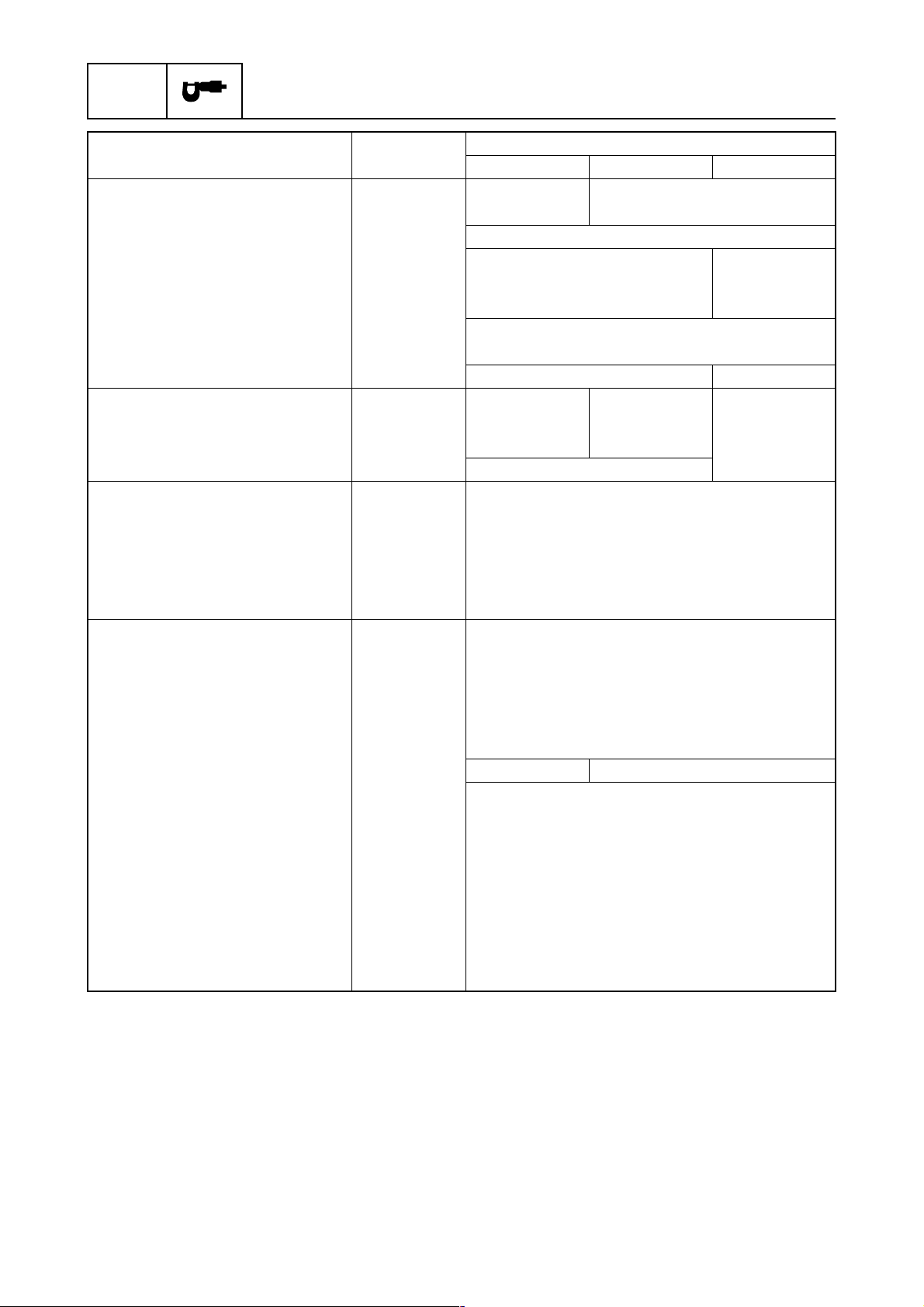
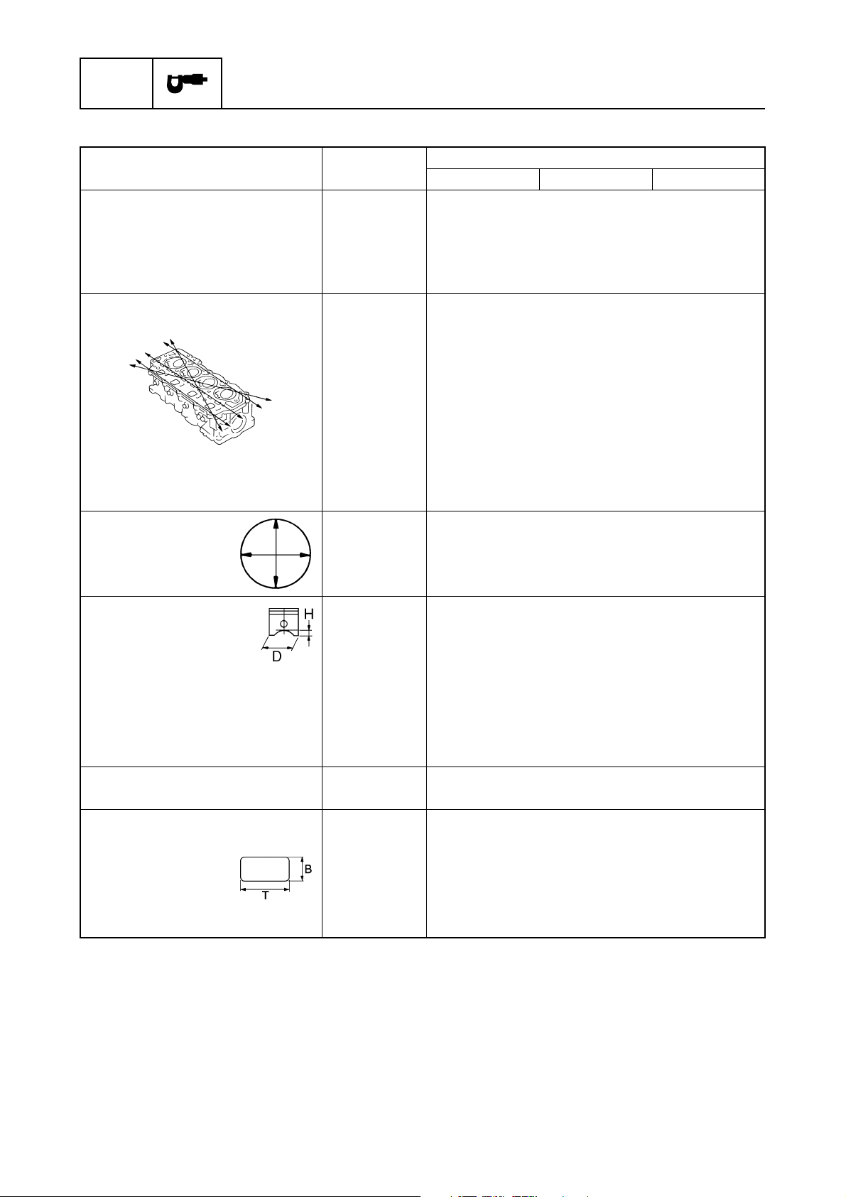
Cylinder head
Warpage limit mm (in) 0.10 (0.0039)
(lines indicate straightedge
position)
Journal inside diameter mm (in) 37.000–37.025 (1.4567–1.4577)
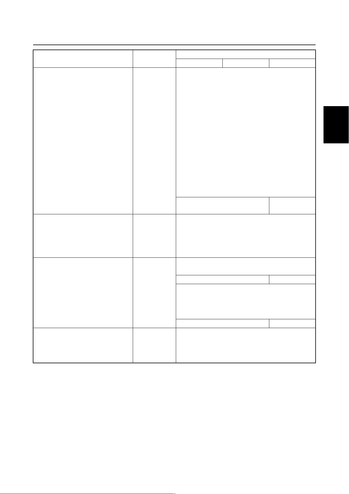
Cylinders
Bore size mm (in) 65.000–65.015 (2.5591–2.5596)
Taper limit mm (in) 0.08 (0.0032)
Out-of-round limit mm (in) 0.05 (0.0020)
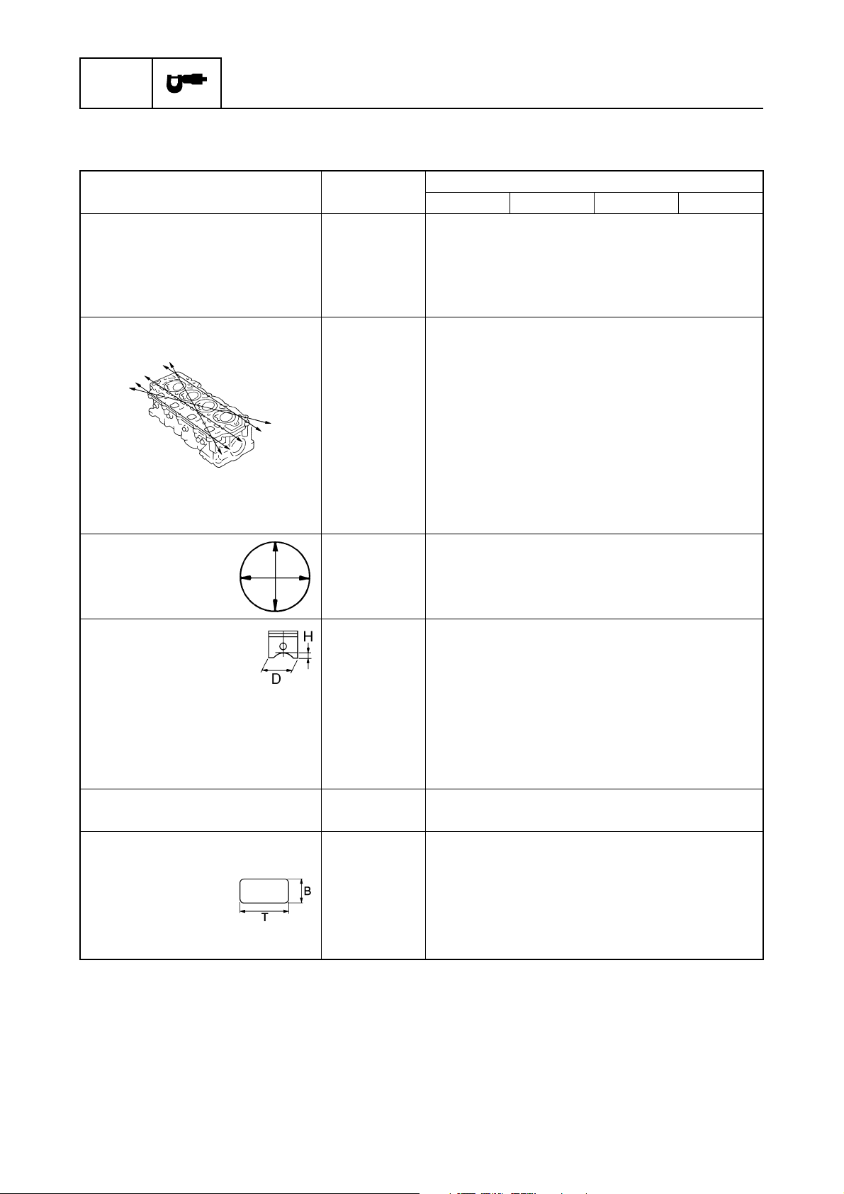
Pistons
Piston diameter (D) mm (in) 64.950–64.965 (2.5571–2.5577)
Measuring point (H) mm (in) 5.0 (0.20)
Piston clearance mm (in) 0.035–0.065 (0.0014–0.0026)
Piston pin boss bore mm (in) 15.974–15.985 (0.6289–0.6293)
Oversize piston diameter
1st mm (in) 65.200–65.215 (2.5669–2.5675)
2nd mm (in) 65.450–65.465 (2.5768–2.5774)
Piston pins
Outside diameter mm (in) 15.965–15.970 (0.6285–0.6287)
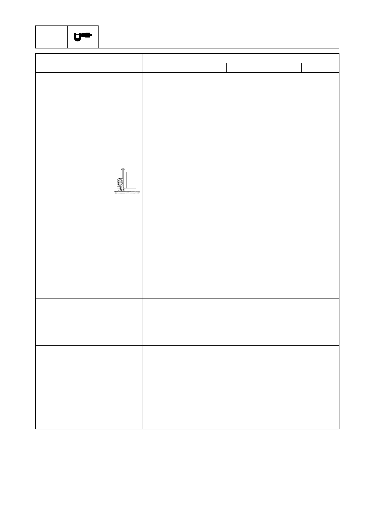
Piston rings
Top ring
Dimension B mm (in) 1.17–1.19 (0.0461–0.0469)
Dimension T mm (in) 2.30–2.50 (0.0905–0.0984)
End gap mm (in) 0.15–0.30 (0.0059–0.0118)
Side clearance mm (in) 0.02–0.06 (0.0008–0.0024)
(*1)
Measure conditions:
Ambient temperature 20 °C (68 °F), wide open throttle, with spark plugs removed from all cylinders.
The figures are for reference only.
(*2)
The figures are for reference only.
Model
960 (9.6, 139.2)
2
2-5
6C13G11
Page 29

Maintenance specification
Item Unit
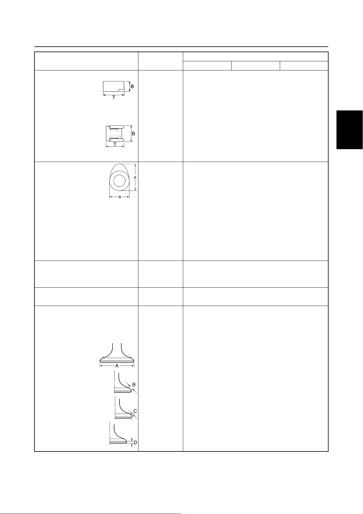
2nd piston ring
Dimension B mm (in) 1.47–1.49 (0.0579–0.0587)
Dimension T mm (in) 2.60–2.80 (0.1024–0.1102)
End gap mm (in) 0.30–0.50 (0.0118–0.0197)
Side clearance mm (in) 0.02–0.06 (0.0008–0.0024)
Oil ring
Dimension B mm (in) 2.36–2.48 (0.0929–0.0976)
Dimension T
End gap mm (in) 0.20–0.70 (0.0079–0.0276)
Side clearance mm (in) 0.04–0.18 (0.0016–0.0071)
Camshaft
Intake (A) mm (in) 30.888–30.988 (1.2161–1.2200)
Exhaust (A) mm (in) 30.824–30.924 (1.2135–1.2175)
Intake and
exhaust (B)
Camshaft journal diameter
#1
Camshaft journal diameter
#2, #3, #4
Camshaft journal oil clearance mm (in) 0.045–0.090 (0.0018–0.0035)
Camshaft runout limit mm (in) 0.03 (0.0012)
Rocker arm shaft
Rocker arm shaft outside
diameter
Rocker arms
Rocker arm inside diameter mm (in) 16.000–16.018 (0.6299–0.6306)
Valves
Valve clearance (cold)
Intake mm (in) 0.20
Exhaust mm (in) 0.30
Head diameter (A)
Intake mm (in) 31.90–32.10 (1.256–1.264)
Exhaust mm (in) 26.60–26.80 (1.047–1.055)
Face width (B)
Intake mm (in) 1.98–2.40 (0.078–0.094)
Exhaust mm (in) 2.16–2.79 (0.085–0.110)
Seat contact width (C)
Intake and exhaust mm (in) 1.3–1.5 (0.051–0.059)
Margin thickness (D)
Intake mm (in) 0.8–1.2 (0.031–0.047)
Exhaust mm (in) 1.0–1.4 (0.039–0.055)
(*1)
mm (in) 2.75 (0.1083)
mm (in) 25.950–26.050 (1.0216–1.0256)
mm (in) 36.925–36.945 (1.4537–1.4545)
mm (in) 36.935–36.955 (1.4541–1.4549)
mm (in) 15.971–15.991 (0.6288–0.6296)
F50FED F50FEHT F50FET FT50GET
Model
±
0.05 (0.008
±
0.05 (0.012
±
±
0.002)
0.002)
1
2
3
4
5
6
7
8
9
(*1)
The figures are for reference only.
6C13G11
2-6
Page 30
SPEC
Specifications
Item Unit
Stem diameter
Intake mm (in) 5.475–5.490 (0.2156–0.2161)
Exhaust mm (in) 5.460–5.475 (0.2150–0.2156)
Guide inside diameter
Intake and exhaust mm (in) 5.500–5.512 (0.2165–0.2170)
Stem-to-guide clearance
Intake and exhaust mm (in) 0.025–0.052 (0.0010–0.0020)
Stem runout limit
Intake mm (in) 0.05 (0.0020)
Exhaust mm (in) 0.03 (0.0012)
Valve springs
Free length mm (in) 39.85 (1.5689)
Tilt limit mm (in) 1.7 (0.07)
Connecting rods
Small end inside diameter mm (in) 15.985–15.998 (0.6293–0.6298)
Big end inside diameter mm (in) 36.000–36.024 (1.4173–1.4183)
Connecting rod big end side
clearance
Crankpin oil clearance mm (in) 0.016–0.040 (0.0006–0.0016)
Big end bearing thickness
Yellow mm (in) 1.500–1.504 (0.0591–0.0592)
Red mm (in) 1.496–1.500 (0.0589–0.0591)
Pink mm (in) 1.492–1.496 (0.0587–0.0589)
Green mm (in) 1.488–1.492 (0.0586–0.0587)
Crankshaft
Crankshaft journal diameter mm (in) 42.984–43.000 (1.6923–1.6929)
Crankpin diameter mm (in) 32.984–33.000 (1.2986–1.2992)
Crankpin width mm (in) 21.000–21.070 (0.8268–0.8295)
Runout limit mm (in) 0.03 (0.0012)
Crankcase
Crankshaft main journal oil
clearance
Crankcase main journal
bearing thickness
Yellow mm (in) 1.502–1.506 (0.0591–0.0592)
Red mm (in) 1.498–1.502 (0.0590–0.0591)
Pink mm (in) 1.494–1.498 (0.0588–0.0590)
Green mm (in) 1.490–1.494 (0.0587–0.0588)
mm (in) 0.05–0.22 (0.0020–0.0087)
mm (in) 0.012–0.036 (0.0005–0.0014)
F50FED F50FEHT F50FET FT50GET
Model
2-7
6C13G11
Page 31

Maintenance specification
Item Unit
Oil pump
Type Trochoid
Outer rotor-to-housing
clearance
Outer rotor-to-inner rotor
clearance limit
Rotor-to-cover clearance mm (in) 0.03–0.08 (0.0012–0.0031)
Relief valve operating
pressure
Thermostat
Opening temperature °C (°F) 58–62 (136–144)
Fully open temperature °C (°F) 70 (158)
Valve open lower limit mm (in) 3.0 (0.12)
Lower unit
Item Unit
Gear backlash
Pinion-to-forward gear mm (in) 0.35–0.81 (0.0138–0.0319) 0.09–0.62
Pinion-to-reverse gear mm (in) 0.89–1.34 (0.0350–0.0528) —
Pinion shims mm 0.10, 0.12, 0.15, 0.18, 0.30, 0.40, 0.50
Forward gear shims mm 0.10, 0.12, 0.15, 0.18, 0.30, 0.40, 0.50
Reverse gear shims mm 0.10, 0.12, 0.15, 0.18, 0.30, 0.40,
mm (in) 0.09–0.15 (0.0035–0.0059)
mm (in) 0.12 (0.0047)
kPa
(kgf/cm
2
, psi)
F50FED F50FEHT F50FET FT50GET
350–450 (3.5–4.5, 50.8–62.3)
F50FED F50FEHT F50FET FT50GET
Model
Model
(0.0035–
0.0244)
0.50
1
2
3
4
5
—
6
6C13G11
7
8
9
2-8
Page 32

SPEC
Electrical
Specifications
Item Unit
F50FED F50FEHT F50FET FT50GET
Model
Ignition and ignition control
system
Ignition timing range
(*1)
Degree ATDC 10-BTDC 25
Spark plug gap mm (in) 0.8–0.9 (0.031–0.035)
Ignition coil resistance
Primary coil (R – B/W)
at 20 °C (68 °F)
Ω
1.53–2.07
Secondary coil
at 20 °C (68 °F) k
Spark plug wire resistance k
Ω
Ω
12.50–16.91
1.9–5.0
ECM output peak voltage
(B/R, B/W – ground)
at cranking (loaded) V 240
at 1,500 r/min (loaded) V 290
at 3,500 r/min (loaded) V 300
Pulser coil output peak voltage
(W/R – W/B)
at cranking (unloaded) V 7.9
at cranking (loaded) V 7.2
at 1,500 r/min (loaded) V 20.7
at 3,500 r/min (loaded) V 32.0
Pulser coil resistance
(*2)
Ω
396–594
(W/B – W/R)
Pulser coil air gap mm (in) 0.75 ± 0.25 (0.030 ± 0.010)
Throttle position sensor
Output voltage (P – B) V 0.8–1.2 at engine idle speed
Sensor assembly resistance
at 20 °C (68 °F) k
at 80 °C (176 °F) k
(*2)
Ω
Ω
5.4–6.6
0.282–0.382
Cooling water temperature
sensor resistance
at 20 °C (68 °F) k
at 60 °C (140 °F) k
at 100 °C (212 °F) k
(*2)
(B/Y – B)
Ω
Ω
Ω
2.439
0.589
0.193
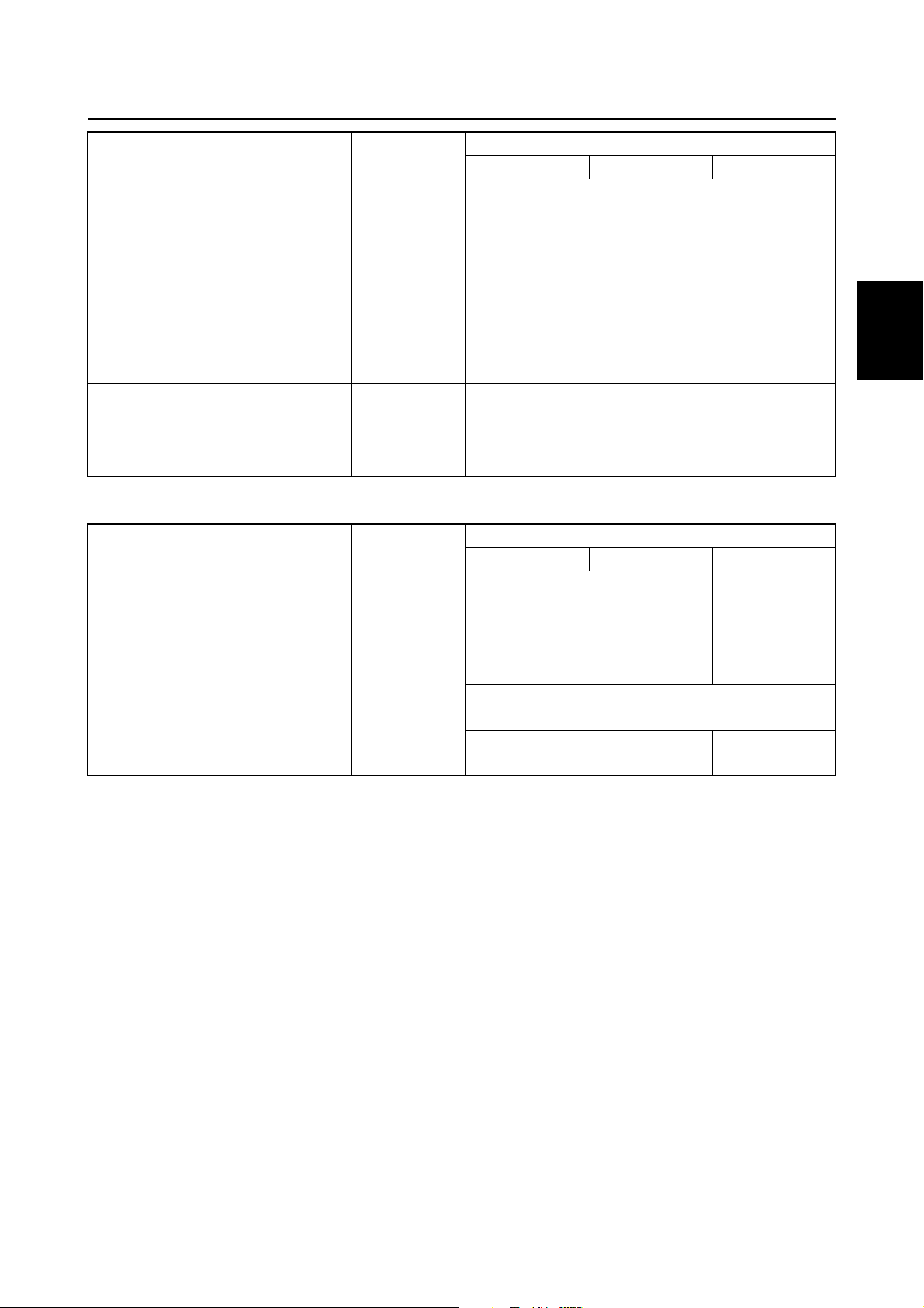
Fuel control system
Fuel injector resistance
at 21 °C (70 °F)
Solenoid valve resistance
at 20 °C (68 °F)
(*1)
The actual ignition timing may vary according to environmental conditions.
The figures are for reference only and do not represent the ignition timing figures from the fully closed position to the fully open position of the throttle valve.
(*2)
The figures are for reference only.
(*2)
(*2)
Ω
Ω
12.0
30.0–34.0
2-9
6C13G11
Page 33

Maintenance specification
Item Unit
Starter motor
Type Sliding gear
Output kW 1.4
Cranking time limit Second 30
Brushes
Standard length mm (in) 15.5 (0.61)
Wear limit mm (in) 9.5 (0.37)
Commutator
Standard diameter mm (in) 29.0 (1.14)
Wear limit mm (in) 28.0 (1.10)
Mica
Standard undercut mm (in) 0.8 (0.03)
Wear limit mm (in) 0.2 (0.01)
Charging system
Fuse A 20, 30
Stator coil output peak voltage
(W – W)
at cranking (unloaded) V 13.2
at 1,500 r/min (unloaded) V 42.2
at 3,500 r/min (unloaded) V 96.6
Stator coil resistance
at 20 °C (68 °F) (W – W)
Rectifier Regulator output
peak voltage (R – B)
at 1,500 r/min (unloaded) V 13.0
at 3,500 r/min (unloaded) V 13.0
Power trim and tilt system
Trim sensor
Setting resistance (P – B)
Resistance (P – B)
Fluid type ATF Dexron
Brushes
Standard limit mm (in) 11.0 (0.43)
Wear limit mm (in) 4.5 (0.18)
Commutator
Standard limit mm (in) 19.0 (0.75)
Wear limit mm (in) 18.0 (0.71)
Mica
Standard undercut mm (in) 1.5 (0.06)
(*1)
The figures are for reference only.
(*1)
Ω
Ω
Ω
F50FED F50FEHT F50FET FT50GET
Model
0.52–0.63
9–11
9–288.3
1
2
3
4
5
6
II
7
8
9
6C13G11
2-10
Page 34
SPEC
Power unit
Specifications
Item Unit
F60CEHT F60CET FT60DET
Model
Power unit
Minimum compression
pressure
Oil pressure
(*1)
(*2)
kPa
kPa
(kgf/cm2, psi)
(kgf/cm
2
, psi)
960 (9.6, 139.2)
125 (1.25, 18.1) at engine idle speed
Cylinder head
Warpage limit mm (in) 0.10 (0.0039)
(lines indicate straightedge
position)
Journal inside diameter mm (in) 37.000–37.025 (1.4567–1.4577)
Cylinders
Bore size mm (in) 65.000–65.015 (2.5591–2.5596)
Taper limit mm (in) 0.08 (0.0032)
Out-of-round limit mm (in) 0.05 (0.0020)
Pistons
Piston diameter (D) mm (in) 64.950–64.965 (2.5571–2.5577)
Measuring point (H) mm (in) 5.0 (0.20)
Piston clearance mm (in) 0.035–0.065 (0.0014–0.0026)
Piston pin boss bore mm (in) 15.974–15.985 (0.6289–0.6293)
Oversize piston diameter
1st mm (in) 65.200–65.215 (2.5669–2.5675)
2nd mm (in) 65.450–65.465 (2.5768–2.5774)
Piston pins
Outside diameter mm (in) 15.965–15.970 (0.6285–0.6287)
Piston rings
Top ring
Dimension B mm (in) 1.17–1.19 (0.0461–0.0469)
Dimension T mm (in) 2.30–2.50 (0.0905–0.0984)
End gap mm (in) 0.15–0.30 (0.0059–0.0118)
Side clearance mm (in) 0.02–0.06 (0.0008–0.0024)
(*1)
Measure conditions:
Ambient temperature 20 °C (68 °F), wide open throttle, with spark plugs removed from all cylinders.
The figures are for reference only.
(*2)
The figures are for reference only.
2-11
6C13G11
Page 35
Maintenance specification
Item Unit
2nd piston ring
Dimension B mm (in) 1.47–1.49 (0.0579–0.0587)
Dimension T mm (in) 2.60–2.80 (0.1024–0.1102)
End gap mm (in) 0.30–0.50 (0.0118–0.0197)
Side clearance mm (in) 0.02–0.06 (0.0008–0.0024)
Oil ring
Dimension B mm (in) 2.36–2.48 (0.0929–0.0976)
Dimension T
End gap mm (in) 0.20–0.70 (0.0079–0.0276)
Side clearance mm (in) 0.04–0.18 (0.0016–0.0071)
Camshaft
Intake (A) mm (in) 30.888–30.988 (1.2161–1.2200)
Exhaust (A) mm (in) 30.824–30.924 (1.2135–1.2175)
Intake and
exhaust (B)
Camshaft journal diameter
#1
Camshaft journal diameter
#2, #3, #4
Camshaft journal oil clearance mm (in) 0.045–0.090 (0.0018–0.0035)
Camshaft runout limit mm (in) 0.03 (0.0012)
Rocker arm shaft
Rocker arm shaft outside
diameter
Rocker arms
Rocker arm inside diameter mm (in) 16.000–16.018 (0.6299–0.6306)
Valves
Valve clearance (cold)
Intake mm (in) 0.20 ± 0.05 (0.008
Exhaust mm (in) 0.30
Head diameter (A)
Intake mm (in) 31.90–32.10 (1.256–1.264)
Exhaust mm (in) 26.60–26.80 (1.047–1.055)
Face width (B)
Intake mm (in) 1.98–2.40 (0.078–0.094)
Exhaust mm (in) 2.16–2.79 (0.085–0.110)
Seat contact width (C)
Intake and exhaust mm (in) 1.3–1.5 (0.051–0.059)
Margin thickness (D)
Intake mm (in) 0.8–1.2 (0.031–0.047)
Exhaust mm (in) 1.0–1.4 (0.039–0.055)
(*1)
mm (in) 2.75 (0.1083)
mm (in) 25.950–26.050 (1.0216–1.0256)
mm (in) 36.925–36.945 (1.4537–1.4545)
mm (in) 36.935–36.955 (1.4541–1.4549)
mm (in) 15.971–15.991 (0.6288–0.6296)
F60CEHT F60CET FT60DET
±
Model
±
0.002)
0.05 (0.012 ± 0.002)
1
2
3
4
5
6
7
8
9
(*1)
The figures are for reference only.
6C13G11
2-12
Page 36

SPEC
Specifications
Item Unit
Stem diameter
Intake mm (in) 5.475–5.490 (0.2156–0.2161)
Exhaust mm (in) 5.460–5.475 (0.2150–0.2156)
Guide inside diameter
Intake and exhaust mm (in) 5.500–5.512 (0.2165–0.2170)
Stem-to-guide clearance
Intake and exhaust mm (in) 0.025–0.052 (0.0010–0.0020)
Stem runout limit
Intake mm (in) 0.05 (0.0020)
Exhaust mm (in) 0.03 (0.0012)
Valve springs
Free length mm (in) 39.85 (1.5689)
Tilt limit mm (in) 1.7 (0.07)
Connecting rods
Small end inside diameter mm (in) 15.985–15.998 (0.6293–0.6298)
Big end inside diameter mm (in) 36.000–36.024 (1.4173–1.4183)
Connecting rod big end side
clearance
Crankpin oil clearance mm (in) 0.016–0.040 (0.0006–0.0016)
Big end bearing thickness
Yellow mm (in) 1.500–1.504 (0.0591–0.0592)
Red mm (in) 1.496–1.500 (0.0589–0.0591)
Pink mm (in) 1.492–1.496 (0.0587–0.0589)
Green mm (in) 1.488–1.492 (0.0586–0.0587)
Crankshaft
Crankshaft journal diameter mm (in) 42.984–43.000 (1.6923–1.6929)
Crankpin diameter mm (in) 32.984–33.000 (1.2986–1.2992)
Crankpin width mm (in) 21.000–21.070 (0.8268–0.8295)
Runout limit mm (in) 0.03 (0.0012)
Crankcase
Crankshaft main journal oil
clearance
Crankcase main journal
bearing thickness
Yellow mm (in) 1.502–1.506 (0.0591–0.0592)
Red mm (in) 1.498–1.502 (0.0590–0.0591)
Pink mm (in) 1.494–1.498 (0.0588–0.0590)
Green mm (in) 1.490–1.494 (0.0587–0.0588)
mm (in) 0.05–0.22 (0.0020–0.0087)
mm (in) 0.012–0.036 (0.0005–0.0014)
F60CEHT F60CET FT60DET
Model
2-13
6C13G11
Page 37
Maintenance specification
Item Unit
Oil pump
Type Trochoid
Outer rotor-to-housing
clearance
Outer rotor-to-inner rotor
clearance limit
Rotor-to-cover clearance mm (in) 0.03–0.08 (0.0012–0.0031)
Relief valve operating
pressure
Thermostat
Opening temperature °C (°F) 58–62 (136–144)
Fully open temperature °C (°F) 70 (158)
Valve open lower limit mm (in) 3.0 (0.12)
Lower unit
Item Unit
Gear backlash
Pinion-to-forward gear mm (in) 0.35–0.81 (0.0138–0.0319) 0.09–0.62
Pinion-to-reverse gear mm (in) 0.89–1.34 (0.0350–0.0528) —
Pinion shims mm 0.10, 0.12, 0.15, 0.18, 0.30, 0.40, 0.50
Forward gear shims mm 0.10, 0.12, 0.15, 0.18, 0.30, 0.40, 0.50
Reverse gear shims mm 0.10, 0.12, 0.15, 0.18, 0.30,
mm (in) 0.09–0.15 (0.0035–0.0059)
mm (in) 0.12 (0.0047)
kPa
(kgf/cm
2
, psi)
F60CEHT F60CET FT60DET
350–450 (3.5–4.5, 50.8–62.3)
F60CEHT F60CET FT60DET
0.40, 0.50
Model
Model
(0.0035–
0.0244)
1
2
3
4
5
—
6
6C13G11
7
8
9
2-14
Page 38

SPEC
Electrical
Specifications
Item Unit
F60CEHT F60CET FT60DET
Model
Ignition and ignition control
system
Ignition timing range
(*1)
Degree ATDC 10-BTDC 24
Spark plug gap mm (in) 0.8–0.9 (0.031–0.035)
Ignition coil resistance
Primary coil (R – B/W)
at 20 °C (68 °F)
Ω
1.53–2.07
Secondary coil
at 20 °C (68 °F) k
Spark plug wire resistance k
Ω
Ω
12.50–16.91
1.9–5.0
ECM output peak voltage
(B/R, B/W – ground)
at cranking (loaded) V 240
at 1,500 r/min (loaded) V 290
at 3,500 r/min (loaded) V 300
Pulser coil output peak voltage
(W/B – W/R)
at cranking (unloaded) V 7.9
at cranking (loaded) V 7.2
at 1,500 r/min (loaded) V 20.7
at 3,500 r/min (loaded) V 32.0
Pulser coil resistance
(*2)
Ω
396–594
(W/B – W/R)
Pulser coil air gap mm (in) 0.75 ± 0.25 (0.030 ± 0.010)
Throttle position sensor
Output voltage (P – B) V 0.8–1.2 at engine idle speed
Sensor assembly resistance
at 20 °C (68 °F) k
at 80 °C (176 °F) k
(*2)
Ω
Ω
5.4–6.6
0.282–0.382
Cooling water temperature
sensor resistance
at 20 °C (68 °F) k
at 60 °C (140 °F) k
at 100 °C (212 °F) k
(*2)
(B/Y – B)
Ω
Ω
Ω
2.439
0.589
0.193
Fuel control system
Fuel injector resistance
at 21 °C (70 °F)
Solenoid valve resistance
at 20 °C (68 °F)
(*1)
The actual ignition timing may vary according to environmental conditions.
The figures are for reference only and do not represent the ignition timing figures from the fully closed
position to the fully open position of the throttle valve.
(*2)
The figures are for reference only.
(*2)
(*2)
Ω
Ω
12.0
30.0–34.0
2-15
6C13G11
Page 39

Maintenance specification
Item Unit
Starter motor
Type Sliding gear
Output kW 1.4
Cranking time limit Second 30
Brushes
Standard length mm (in) 15.5 (0.61)
Wear limit mm (in) 9.5 (0.37)
Commutator
Standard diameter mm (in) 29.0 (1.14)
Wear limit mm (in) 28.0 (1.10)
Mica
Standard undercut mm (in) 0.8 (0.03)
Wear limit mm (in) 0.2 (0.01)
Charging system
Fuse A 20, 30
Stator coil output peak voltage
(W – W)
at cranking (unloaded) V 13.2
at 1,500 r/min (unloaded) V 42.2
at 3,500 r/min (unloaded) V 96.6
Stator coil resistance
at 20 °C (68 °F) (W – W)
Rectifier Regulator output
peak voltage (R – B)
at 1,500 r/min (unloaded) V 13.0
at 3,500 r/min (unloaded) V 13.0
Power trim and tilt system
Trim sensor
Setting resistance (P – B)
Resistance (P – B)
Fluid type ATF Dexron
Brushes
Standard limit mm (in) 11.0 (0.43)
Wear limit mm (in) 4.5 (0.18)
Commutator
Standard limit mm (in) 19.0 (0.75)
Wear limit mm (in) 18.0 (0.71)
Mica
Standard undercut mm (in) 1.5 (0.06)
(*1)
The figures are for reference only.
(*1)
Ω
Ω
Ω
F60CEHT F60CET FT60DET
Model
0.52–0.63
9–11
9–288.3
1
2
3
4
5
6
II
7
8
9
6C13G11
2-16
Page 40

SPEC
Specifications
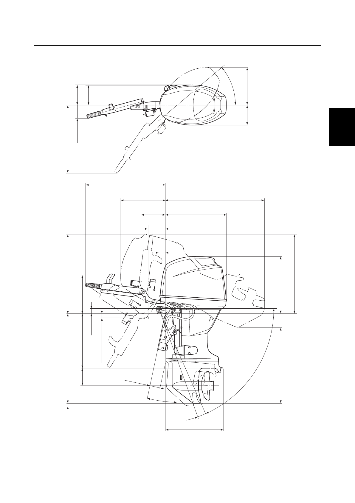
Dimensions
Exterior
F50, F60 (Remote control model)
188 (7.4)
192 (7.6)
mm (in)
˚
0
4
360 (14.2)192
(7.6)
A: 762 (30.0)
B: 759 (29.9)
A: 148 (5.8)
B: 147 (5.8)
354 (13.9)
49 (1.9)
A: 406 (16.0)
B: 417 (16.4)
122 (4.8)
A: 25 (1.0)
B: 22 (0.9)
A: 930 (36.6)
B: 932 (36.7)
584 (23.0)
62 (2.4)
545 (21.5)
527 (20.7)
870 (34.3)
175 (6.9)
24 (0.9)
A: Hydro tilt model (For Europe)
B: Power trim and tilt model
2-17
97 (3.8)
A: 63˚
B: 65˚
1
2
˚
˚
4
533 (21.0)
A: 682 (26.9)
B: 708 (27.9)
S6C12030
6C13G11
Page 41
F50, F60 (Tiller handle model)
192 (7.6)
188 (7.4)
(*1)
Maintenance specification
mm (in)
˚
0
4
360 (14.2)
(7.6)
192
1
124 (4.9)
645 (25.4)
759 (29.9)
354 (14.0)
755 (29.7)
417 (16.4)
226 (8.9)
2
3
932 (36.7)
584 (23.0)
4
164 (6.5)
62 (2.4)
5
758 (29.8)
545 (21.5)
6
49 (1.9)
527 (20.7)
870 (343)
175 (6.9)
24 (0.9)
Power trim and tilt model
(*1)
For Oceania
6C13G11
37 (1.5)
97 (3.8)
7
65˚
1
2
˚
˚
4
533 (21.0)
708 (27.9)
8
9
S6C12020E
2-18
Page 42

SPEC
FT50, FT60
Specifications
188 (7.4)
192 (7.6)
˚
0
4
mm (in)
360 (14.2)
192 (7.6)
759 (29.9)
354 (13.9)
417 (16.4)
147 (5.8)
122 (4.8)
62 (2.4)
22 (0.9)
L: 996 (39.2)
X: 1,099 (43.3)
584 (23.0)
62 (2.4)
545 (21.5)
L: 910 (35.8)
X: For Oceania
2-19
L: 530 (20.9)
X: 644 (25.4)
X: 1,024 (40.3)
191 (7.5)
24 (0.9)
L : 98 (3.9)
X : 114 (4.5)
12˚
˚
4
561 (22.1)
65˚
L: 746 (29.4)
X: 812 (32.0)
S6C12010
6C13G11
Page 43

Clamp bracket
Maintenance specification
mm (in)
1
180 (7.1)
163.5 (6.4)
180 (7.1)
163.5 (6.4)
50.8 (2.0)
18.5 (0.7)
254.0 (10.0)
350 (13.8)
2
3
4
70.5 (2.78)
13 (0.5)
5
55.5 (2.2)
126 (5.0)126 (5.0)
13 (0.5)
6
7
8
9
S6C12070
6C13G11
2-20
Page 44
SPEC
Specifications
Tightening torques
2
Specified torques
Part to be tightened Thread size
Fuel system
Fuel filter cup — 30.32.2
Fuel pump screw M5 3 0.3 2.2
Fuel pump valve screw M3 0.5 0.05 0.36
Idle speed control screw M5 4 0.4 3.0
Sensor assembly screw M5 4 0.4 3.0
Fuel cooler screw M6 3 0.3 2.2
Fuel rail mounting bolt M6 9 0.9 6.6
Throttle body mounting bolt M6 9 0.9 6.6
Pressure regulator bolt M6 5 0.5 3.7
Drain screw — 1.5 0.15 1.1
Joint screw — 40.43.0
Vapor separator cover screw M5 3 0.3 2.2
Plate screw M4 2 0.2 1.5
Power unit
Power unit mounting bolt M8 27 2.7 20.0
Shift position switch screw M4 2 0.2 1.5
Stator coil bracket bolt M6 4 0.4 3.0
Pulser coil bolt M5 4 0.4 3.0
Flywheel magnet nut M20 157 15.7 115.8
Starter motor bolt M8 29 2.9 21.4
Starter motor terminal nut M8 9 0.9 6.6
Starter relay lead bolt M6 4 0.4 3.0
Starter motor lead screw M4 2 0.2 1.5
Starter relay holder screw M6 3 0.3 2.2
Main and fuel pump relay screw M6 3 0.3 2.2
ECM cover screw M6 3 0.3 2.2
Self diagnosis connector screw M6 3 0.3 2.2
Ignition coil bolt M6 7 0.7 5.2
Oil filter — 18 1.8 13.3
PTT relay nut M6 4 0.4 3.0
PTT motor lead bolt M6 4 0.4 3.0
Positive battery lead nut M8 9 0.9 6.6
Drive sprocket nut M41 140 14.0 103.3
Driven sprocket bolt M10 38 3.8 28.0
Rocker arm lock nut M10 14 1.4 10.3
Rocker arm shaft bolt M8 18 1.8 13.3
Tightening torques
N·mkgf·mft·lb
2-21
6C13G11
Page 45
Tightening torques
Part to be tightened Thread size
1st
2nd 12 1.2 8.9
Cylinder head bolt
Spark plug — 17 1.7 12.5
Cooling water temperature sensor — 23 2.3 17.0
Oil pressure switch — 80.85.9
Oil pressure switch lead bolt M4 2 0.2 1.5
Exhaust cover bolt
Exhaust cover plug
Oil filter union bolt — 40 4.0 29.5
Oil pump screw M6 4 0.4 3.0
Crankcase bolt
Connecting rod cap bolt
Lower unit (F50, F60)
Gear oil drain screw — 90.96.6
Gear oil check screw — 90.96.6
Lower case mounting bolt M10 39 3.9 28.8
Propeller nut M16 34 3.4 25.1
Ring nut — 103 10.3 76.0
Cooling water inlet cover screw — 40.43.0
Pinion nut M16 74 7.4 54.6
Propeller shaft housing bolt M8 16 1.6 11.8
Lower unit (FT50, FT60)
Gear oil drain screw — 90.96.6
Gear oil check screw — 90.96.6
Lower case mounting bolt (nut) M10 39 3.9 28.8
Propeller nut M16 34 3.4 25.1
Ring nut — 103 10.3 76.0
Cooling water inlet cover screw — 40.43.0
Pinion nut M16 93 9.3 68.6
Propeller shaft housing bolt M8 16 1.6 11.8
1st
2nd 23 2.3 17.0
3rd 90°
1st
2nd 12 1.2 8.9
1st
2nd 12 1.2 8.9
1st
2nd 30 3.0 22.1
1st
2nd 17 1.7 12.5
M6
M9
M6
M14 23 2.3 17.0
M18 55 5.5 40.6
M6
M8
—
Tightening torques
N·mkgf·mft·lb
60.64.4
12 1.2 8.9
60.64.4
60.64.4
15 1.5 11.1
60.64.4
1
2
3
4
5
6
7
8
9
6C13G11
2-22
Page 46

SPEC
Specifications
Part to be tightened Thread size
Bracket unit
Retaining plate bolt M6 10 1.0 7.4
Tiller handle nut — 37 3.7 27.3
Self-locking nut — 40.43.0
Engine stop lanyard switch nut — 20.21.5
Tiller handle bracket nut — 37 3.7 27.3
Tiller handle bracket bolt M12 37 3.7 27.3
Engine start switch nut — 40.43.0
Shift rod detent bolt — 18 1.8 13.3
PTT switch bracket bolt M6 10 1.0 7.4
Flushing hose adapter screw M6 2 0.2 1.5
Engine oil drain bolt M14 17 1.7 12.5
Muffler bolt M6 10 1.0 7.4
Exhaust manifold bolt M6 10 1.0 7.4
Oil pan bolt M8 27 2.7 20.0
Oil strainer bolt M6 10 1.0 7.4
Upper mounting nut M8 24 2.4 17.7
Self-locking nut — 22 2.2 16.2
Grease nipple — 30.32.2
Power trim and tilt unit
PTT motor bolt M5 4 0.4 3.0
Reservoir cap — 70.75.2
Manual valve — 20.21.5
Gear pump bolt M5 5 0.5 3.7
Lever bolt M3 3 0.3 2.2
Relief valve seat cap bolt
Gear pump housing bolt M5 5 0.5 3.7
Gear pump bracket bolt
Tilt cylinder end screw — 110 11.0 81.1
Trim cylinder end screw — 80 8.0 59.0
Tilt piston bolt M12 61 6.1 45.0
M4 4 0.4 3.0
M5 5 0.5 3.7
M3 3 0.3 2.2
M5 4 0.4 3.0
Tightening torques
N·mkgf·mft·lb
2-23
6C13G11
Page 47

General torques
This chart specifies tightening torques for
standard fasteners with a standard ISO
thread pitch. Tightening torque specifications
for special components or assemblies are
provided in applicable sections of this manual. To avoid warpage, tighten multi-fastener
assemblies in a crisscross fashion and progressive stages until the specified torque is
reached. Unless otherwise specified, torque
specifications require clean, dry threads.
Components should be at room temperature.
General torque
Nut (A) Bolt (B)
8 mm M5 5 0.5 3.6
10 mm M6 8 0.8 5.8
12 mm M8 18 1.8 13
14 mm M10 36 3.6 25
17 mm M12 43 4.3 31
specifications
N·mkgf·mft·lb
Tightening torques
1
2
3
4
5
6
7
8
9
6C13G11
2-24
Page 48

SPEC
Specifications
— MEMO —
2-25
6C13G11
Page 49

CHK
ADJ
Periodic checks and adjustments
Special service tools .....................................................................................3-1
Maintenance interval chart............................................................................3-2
Top cowling ....................................................................................................3-3
Checking the top cowling...........................................................................3-3
Fuel system ....................................................................................................3-3
Checking the fuel joint and fuel hoses (fuel joint-to-fuel injector) ..............3-3
Checking the fuel filter ...............................................................................3-3
Power unit.......................................................................................................3-3
Checking the engine oil level.....................................................................3-3
Changing the engine oil using an oil changer............................................3-4
Changing the engine oil by draining it .......................................................3-4
Replacing the oil filter ................................................................................3-5
Checking the timing belt ............................................................................3-6
Replacing the timing belt ...........................................................................3-6
Checking the spark plugs ..........................................................................3-8
Checking the thermostat............................................................................3-9
Checking the cooling water passage.......................................................3-10
Control system.............................................................................................3-10
Checking the engine idle speed ..............................................................3-10
Adjusting the throttle link and throttle cable.............................................3-10
Checking the gear shift operation............................................................3-12
1
2
3
4
5
Bracket unit ..................................................................................................3-13
Checking the power trim and tilt operation .............................................. 3-13
Checking the hydro tilt unit operation ......................................................3-13
Checking the power trim and tilt fluid level ..............................................3-14
Lower unit.....................................................................................................3-14
Checking the gear oil level ......................................................................3-14
Changing the gear oil ..............................................................................3-15
Checking the lower unit for air leakage ...................................................3-15
Checking the propeller.............................................................................3-16
General..........................................................................................................3-16
Checking the anodes...............................................................................3-16
Checking the battery................................................................................3-17
Lubricating the outboard motor................................................................3-18
6
7
8
9
6C13G11
Page 50
CHK
ADJ
Periodic checks and adjustments
Special service tools
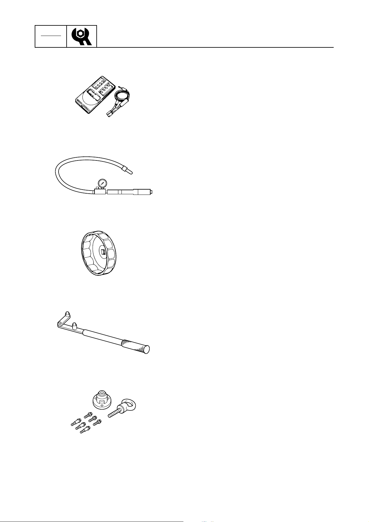
Digital tachometer
90890-06760
Leakage tester
90890-06840
3
Oil filter wrench
90890-01426
Flywheel holder
90890-06522
Flywheel puller
90890-06521
3-1
6C13G11
Page 51
Special service tools / Maintenance interval chart
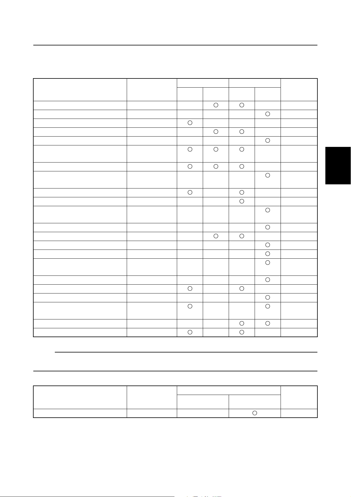
Maintenance interval chart
Use the following chart as a guideline for general maintenance.
Adjust the maintenance intervals according to the operating conditions of the outboard motor.
Initial Every
Item Remarks
Anodes (external) Check/replace 3-16
Anodes (internal) Check/replace 3-16
Battery Check/charge 3-17
Cooling water passages Clean 3-10
Top cowling Check 3-3
Fuel filter
(can be disassembled)
Fuel system Check 3-3
Fuel tank
(Yamaha portable tank)
Gear oil Change 3-14
Lubrication points Lubricate 3-18
Engine idle speed
(EFI models)
Power trim and tilt unit Check 3-13
Propeller and cotter pin Check/replace 3-16
Shift link/shift cable Check/adjust 3-12
Thermostat Check 3-9
Throttle link/throttle cable/
throttle pick-up timing
Water pump Check 6-7, 6-32
Engine oil Check/change 3-3
Oil filter Change 3-5
Spark plugs Clean/adjust/
Timing belt Check/replace 3-6
Valve clearance (OHC) Check/adjust 5-4
Check/replace 3-3
Check/clean —
Check/adjust 3-10
Check/adjust 3-10
replace
10 hours
(1 month)
50 hours
(3 months)
100 hours
(6 months)
200 hours
(1 year)
Refer to
page
3-8
3
1
2
3
4
5
6
7
NOTE:
When operating in salt water, turbid or muddy water, the engine should be flushed with clean water
after each use.
Every
Item Remarks
Timing belt Replace 3-6
6C13G11
500 hours
(2.5 years)
1,000 hours
(5 years)
Refer to
page
3-2
8
9
Page 52
CHK
ADJ
Periodic checks and adjustments
Top cowling
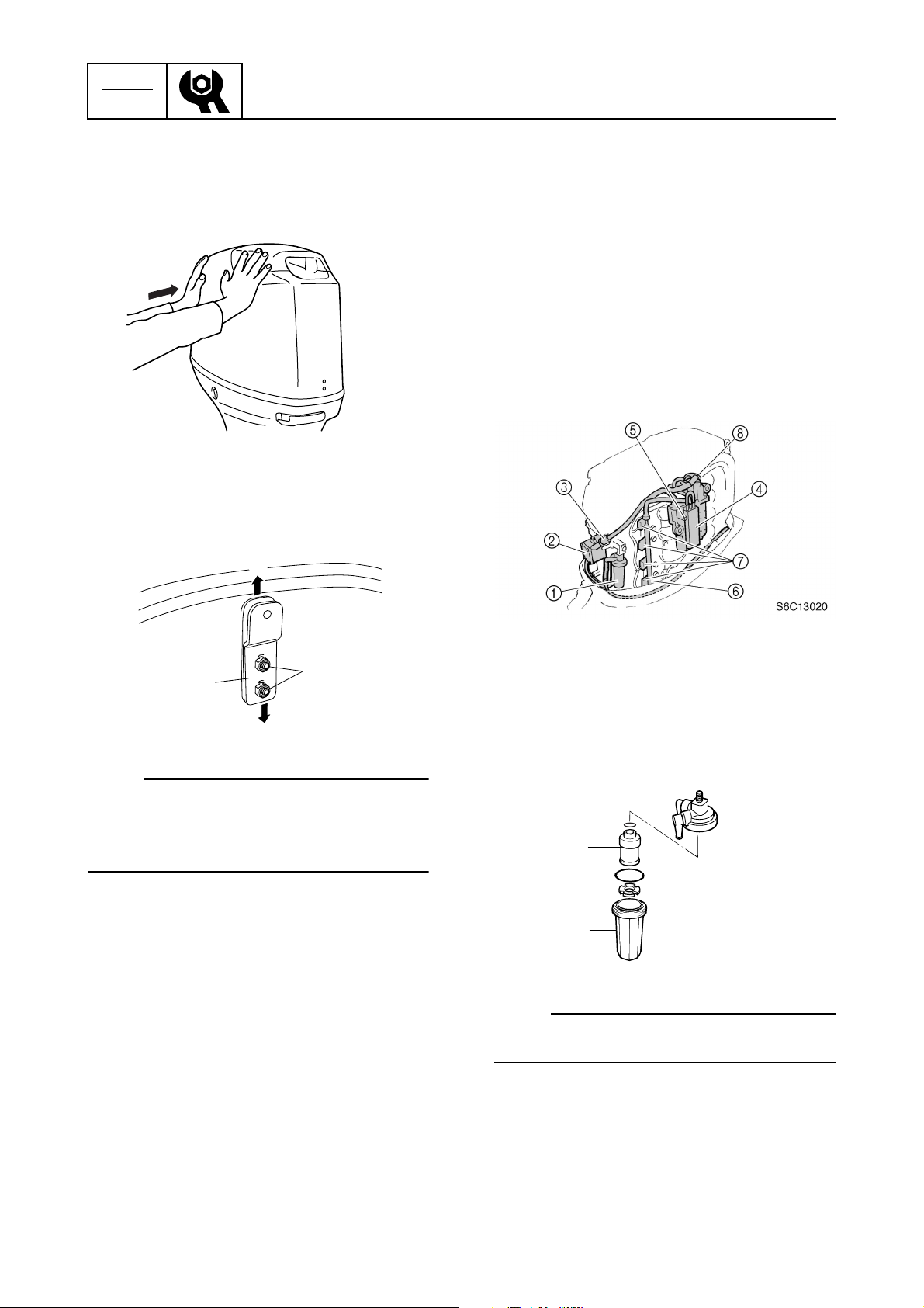
Checking the top cowling
1. Check the fitting by pushing the cowling
with both hands. Adjust if necessary.
S6C13010
2. Loosen the nuts 1.
3. Move the hook 2 up or down slightly to
adjust its position.
a
3
2. Check the low-pressure fuel hose connections and fuel joint for leaks. Replace
if necessary. Also, check the fuel filter 1,
fuel pump 2, strainer 3, and fuel cooler
4
for leaks or deterioration. Replace if
necessary.
3. Check the high-pressure fuel hose connections for leaks. Replace if necessary.
Also, check the vapor separator 5, fuel
rail 6, fuel injectors 7, and pressure
regulator 8 for leaks or deterioration.
Replace if necessary.
2
b
1
S6D53020
NOTE:
• To loosen the fitting, move the hook in
direction a.
• To tighten the fitting, move the hook in
direction b.
4. Tighten the nuts.
5. Check the fitting again and, if necessary,
repeat steps 2–4.
Fuel system
Checking the fuel joint and fuel
hoses (fuel joint-to-fuel injector)
1. Remove the flywheel magnet cover.
Checking the fuel filter
1. Check the fuel filter element 1 for dirt
and residue and check the fuel filter cup
2
for foreign substances and cracks.
Clean the cup with straight gasoline and
replace the element if necessary.
1
2
S6C13030
NOTE:
3
Be sure not to spill any fuel when removing
the fuel filter cup.
Power unit
3
Checking the engine oil level
1. Place the outboard motor in an upright
position.
3-3
6C13G11
Page 53

2. Remove the oil dipstick, wipe it clean,
and then insert it back into the dipstick
hole.
3. Remove the oil dipstick again to check
the oil level and to check the oil for discoloration and its viscosity.
a
b
S6C11030
NOTE:
• Change the oil if it appears milky or dirty.
• If the engine oil is below the minimum level
mark b, add sufficient oil until the level is
between a and b.
Changing the engine oil using an oil
changer
1. Start the engine, warm it up, and then
turn it off.
2. Remove the oil dipstick and oil filler cap
1
.
1
Top cowling / Fuel system / Power unit
2
4. Operate the oil changer to extract the oil.
NOTE:
Be sure to clean up any oil spills.
5. Pour the specified amount of the recommended engine oil into the oil filler hole.
Recommended engine oil:
4-stroke motor oil
API: SE, SF, SG, SH, or SJ
SAE: 10W-30 or 10W-40
Engine oil quantity:
Without oil filter replacement:
2.5 L (2.64 US qt, 2.20 Imp qt)
6. Install the oil filler cap and oil dipstick,
and then start the engine and warm it up
for 5 minutes.
7. Turn the engine off, and then check the
oil level and correct it if necessary.
3
S6C13330
1
2
3
4
5
6
S6C13050
3. Insert the tube of the oil changer 2 into
the dipstick hole 3.
6C13G11
Changing the engine oil by draining
it
1. Start the engine, warm it up, and then
turn it off.
3-4
7
8
9
Page 54

CHK
T
R
.
.
ADJ
Periodic checks and adjustments
2. Remove the oil dipstick and oil filler cap
1
.
1
S6C13050
3. Place a drain pan under the drain hole,
and then remove the drain bolt 2 and
gasket and let the oil drain completely.
2
S6C13060
7. Turn the engine off, and then check the
oil level and correct it if necessary.
Replacing the oil filter
1. Extract the engine oil with an oil changer
or drain it.
2. Place a rag under the oil filter, and then
remove the oil filter using the oil filter
wrench 1.
1
S6C13070
NOTE:
• Wait more than 5 minutes after turning the
engine off to replace the oil filter.
• Be sure to clean up any oil spills.
NOTE:
Be sure to clean up any oil spills.
4. Install the gasket and drain bolt, and then
tighten it to the specified torque.
Engine oil drain bolt:
T
.
R
.
17 N·m (1.7 kgf·m, 12.5 ft·lb)
5. Pour the specified amount of the recommended engine oil into the oil filler hole.
Recommended engine oil:
4-stroke motor oil
API: SE, SF, SG, SH, or SJ
SAE: 10W-30 or 10W-40
Engine oil quantity:
Without oil filter replacement:
2.5 L (2.64 US qt, 2.20 Imp qt)
6. Install the oil filler cap and oil dipstick,
and then start the engine and warm it up
for 5 minutes.
Oil filter wrench 1: 90890-01426
3. Apply a thin coat of engine oil to the Oring of the new oil filter.
4. Install the oil filter, and then tighten it to
the specified torque using the oil filter
wrench 1.
1
E
S6C13080
Oil filter:
18 N·m (1.8 kgf·m, 13.3 ft·lb)
3-5
6C13G11
Page 55
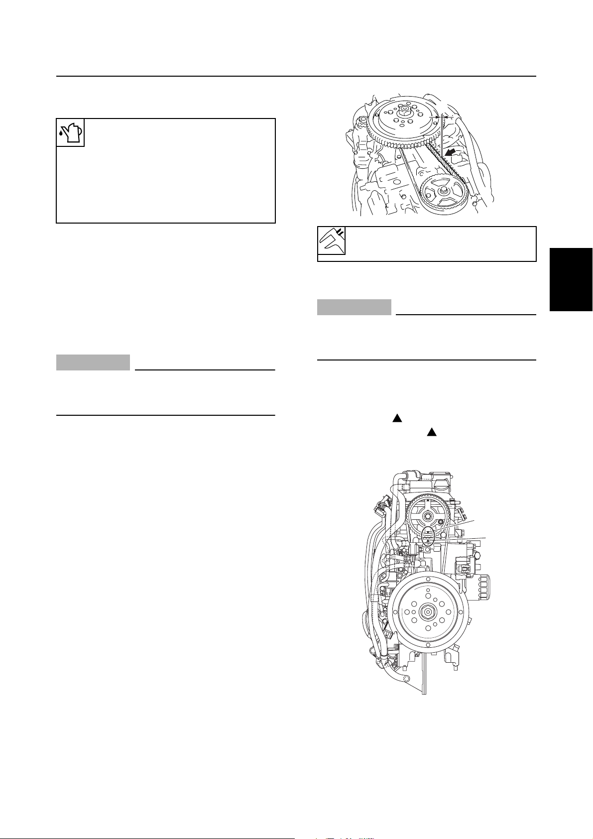
5. Pour the specified amount of the recommended engine oil into the oil filler hole.
Recommended engine oil:
4-stroke motor oil
API: SE, SF, SG, SH, or SJ
SAE: 10W-30 or 10W-40
Engine oil quantity:
With oil filter replacement:
2.7 L (2.85 US qt, 2.38 Imp qt)
6. Install the oil filler cap and oil dipstick,
and then start the engine and warm it up
for 5 minutes.
7. Turn the engine off, and then check the
oil level and correct it if necessary.
Checking the timing belt
CAUTION:
Do not turn the flywheel magnet counterclockwise, otherwise the valve system
may be damaged.
1. Remove the flywheel magnet cover.
2. Remove the solenoid valve.
Power unit
a
S6C13090
Timing belt slack a:
Within 14 mm (0.55 in)
Replacing the timing belt
CAUTION:
Do not turn the flywheel magnet counterclockwise, otherwise the valve system
may be damaged.
1. Remove the flywheel magnet cover.
2. Turn the flywheel magnet clockwise and
align the “ 1” mark a on the driven
sprocket with the “” mark b on the cylinder head.
1
2
3
4
5
3. While turning the flywheel magnet clockwise, check the interior and the exterior
of the timing belt for cracks, damage, or
wear. Replace if necessary.
4. Turn the flywheel magnet clockwise to
transfer the slack of the timing belt from
port to starboard, and then lightly hold
the flywheel magnet in place.
5. Slightly push the timing belt with your finger between the drive gear and driven
gear, and then measure the belt slack.
Replace the timing belt if above specification.
a
b
S6C15850
6
7
8
9
6C13G11
3-6
Page 56

CHK
ADJ
Periodic checks and adjustments
3. Loosen the flywheel magnet nut.
CAUTION:
Apply force in the direction of the arrows
shown to prevent the flywheel holder from
slipping off easily.
Flywheel holder: 90890-06522
4. Remove the flywheel magnet, then the
Woodruff key.
NOTE:
Apply force to the crankshaft end until the flywheel magnet comes off the tapered portion
of the crankshaft.
Flywheel puller: 90890-06521
5. Disconnect the stator coil coupler and
pulser coil coupler, and remove the stator
coil assembly 1.
6. Remove the solenoid valve, and then
remove the timing belt 2 from the driven
sprocket, then from the drive sprocket.
CAUTION:
To prevent damage to the engine or tools,
screw in the puller set bolts evenly and
completely so that the puller plate is parallel to the flywheel magnet.
3-7
CAUTION:
Do not turn the drive sprocket or the
driven sprocket when the timing belt is
not installed. Otherwise the piston and
valves will interfere with each other and
be damaged.
7. Check that the “ 1” mark a on the
driven sprocket is aligned with the “”
mark b on the cylinder head, and that
the “” mark c on the retaining plate is
aligned with the “” mark d on the
crankcase.
6C13G11
Page 57

8. Install a new timing belt 3 onto the drive
T
R
.
.
sprocket, then onto the driven sprocket
with its part number in the upright position.
Power unit
10. Install the solenoid valve and stator coil
assembly, and connect the stator coil
coupler and pulser coil coupler.
11. Install the Woodruff key, then the flywheel magnet.
CAUTION:
Apply force in the direction of the arrows
shown to prevent the flywheel holder from
slipping off easily.
NOTE:
Apply engine oil to the flywheel magnet nut
before installation.
1
2
3
4
5
CAUTION:
• Do not damage the timing belt during
installation.
• Do not twist, turn inside out, or bend the
timing belt beyond the maximum limit of
25 mm (1.0 in), otherwise it can be damaged.
• Do not get oil or grease on the timing
belt.
9. Turn the drive sprocket clockwise two
turns, and then check that the alignment
marks are aligned.
Flywheel holder: 90890-06522
Flywheel magnet nut:
157 N·m (15.7 kgf·m, 115.8 ft·lb)
12. Adjust the pulser coil air gap.
NOTE:
For adjustment procedures, see Chapter 8,
“Checking the pulser coil air gap.”
13. Install the flywheel magnet cover.
Checking the spark plugs
1. Disconnect the spark plug wires, and
then remove the spark plugs.
6
7
8
9
6C13G11
3-8
Page 58
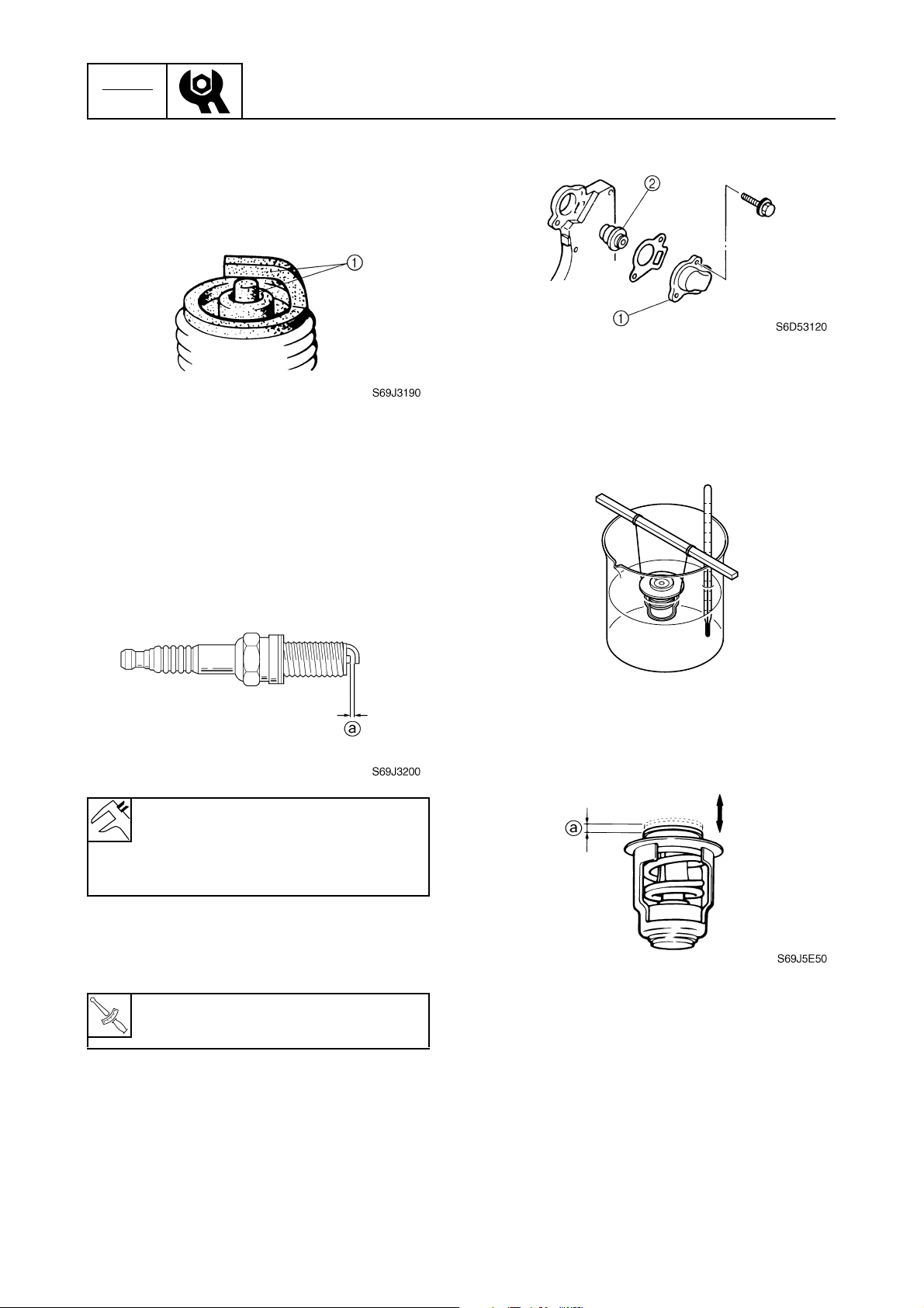
CHK
ADJ
2. Clean the electrodes 1 with a spark plug
cleaner or wire brush. Replace the spark
plug if necessary.
Periodic checks and adjustments
2. Suspend the thermostat in a container of
water.
3. Check the electrodes for erosion and
excessive carbon or other deposits, and
the gasket for damage. Replace the
spark plug if necessary.
4. Check the spark plug gap a. Adjust if out
of specification.
Specified spark plug:
DPR6EB-9 (NGK)
Spark plug gap a:
0.8–0.9 mm (0.031–0.035 in)
3. Place a thermometer in the water and
slowly heat the water.
S69J5E40
4. Check the thermostat valve opening at
the specified water temperatures.
Replace if out of specification.
5. Install the spark plugs, tighten them finger tight, then to the specified torque
using a spark plug wrench.
Spark plug:
T
.
R
.
17 N·m (1.7 kgf·m, 12.5 ft·lb)
Checking the thermostat
1. Remove the cover 1, gasket, and thermostat 2.
3-9
6C13G11
Page 59

Power unit / Control system
Water
temperature
58–62 °C
(136–144 °F)
above
70 °C (158 °F)
5. Install the thermostat, gasket, and cover.
Checking the cooling water passage
1. Check the cooling water inlet cover
and cooling water inlet for clogs. Clean if
necessary.
Valve lift a
0.05 mm
(0.0020 in)
(valve begins to lift)
more than
3.0 mm (0.12 in)
1
È
Control system
Checking the engine idle speed
1. Start the engine and warm it up for 5 minutes.
2. Attach the special service tool to spark
plug wire #1 1, and then check the
engine idle speed.
1
2
3
3
4
1
1
S6C13100
F50, F60
È
2. Place the lower unit in water, and then
start the engine.
3. Check for water flow at the cooling water
pilot hole. If there is no water flow, check
the cooling water passage inside the outboard motor.
1
S6C13110
Digital tachometer: 90890-06760
Engine idle speed: 700–800 r/min
Adjusting the throttle link and
throttle cable
1. Set the remote control lever to the neutral position and fully close the throttle
lever. Set the throttle grip to the fully
closed position.
2. Disconnect the throttle link rod from the
throttle body and the throttle link.
5
6
7
8
9
6C13G11
3-10
Page 60

CHK
ADJ
Periodic checks and adjustments
3. Loosen the locknut 1, and then adjust
the throttle link rod length a.
a
1
S6C13120
Throttle link rod length a:
121 mm (4.76 in)
4. Align the alignment mark b on the throttle control lever with the alignment mark
c
on the bracket.
6. Contact the cam roller 2 on the throttle
control lever to the throttle cam as
shown, and then adjust the position of
the throttle link rod until the joint 3 of the
throttle link rod is aligned with the joint
4
of the control lever.
2
S6C13140
3
c
b
c
b
S6C13130
5. Connect the throttle link rod to the throttle
body.
NOTE:
Connect the end of the throttle link rod that
does not have a locknut to the throttle body.
4
S6C13150
7. Connect the throttle link rod to the throttle
link, and then tighten the locknut.
8. Loosen the locknut 5, remove the clip
6
, and then disconnect the throttle cable
joint 7.
6
5
7
S6C13160
9. Adjust the throttle cam 8 until the alignment mark d on the throttle cam is
aligned with the alignment mark e on
the bracket.
3-11
6C13G11
Page 61

e
8
d
Control system
12. Operate the throttle to check that the
throttle valves fully close and fully open,
and check that the throttle cam contacts
the fully closed stopper when the throttle
is in the fully closed position.
1
13. Check the throttle cable for smooth operation and, if necessary, repeat steps 1–
12.
e
d
S6C13170
10. Adjust the position of the throttle cable
joint until its hole is aligned with the set
pin.
f
NOTE:
Pull the throttle cable towards the set pin to
remove any free play in the cable before
adjusting the position of the throttle cable
joint.
S6C13180
Checking the gear shift operation
1. Check that the gear shift operates
smoothly when shifting it from neutral to
forward or reverse. Adjust the shift cable
length if necessary.
2. Set the gear shift to the neutral position.
3. Loosen the locknut 1, remove the clip
2
, and then disconnect the shift cable
joint 3.
3
2
1
S6C13190
4. Align the center of the set pin a with the
alignment mark b on the bracket.
2
3
4
5
6
7
11. Connect the throttle cable joint, install the
clip, and then tighten the locknut.
WARNING
The throttle cable joint must be screwed
in a minimum of 8.0 mm (0.31 in) f.
6C13G11
a
b
8
9
S6C13200
3-12
Page 62
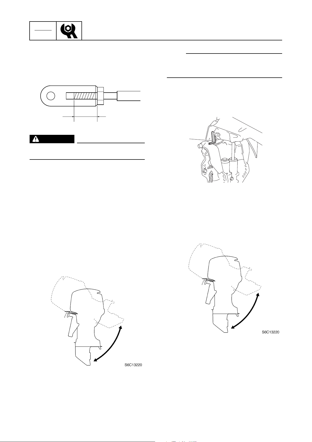
CHK
ADJ
Periodic checks and adjustments
5. Adjust the position of the shift cable joint
until its hole is aligned with the set pin.
c
S69J3370
WARNING
The shift cable joint must be screwed in a
minimum of 8.0 mm (0.31 in) c.
6. Connect the cable joint, install the clip,
and then tighten the locknut.
7. Check the gear shift for smooth operation
and, if necessary, repeat steps 3–6.
Bracket unit
Checking the power trim and tilt
operation
1. Fully tilt the outboard motor up and down
a few times and check the entire trim and
tilt range for smooth operation. Check the
power trim and tilt fluid level if necessary.
NOTE:
Be sure to listen to the winding sound of the
power trim and tilt motor for smooth operation.
2. Fully tilt the outboard motor up, and then
support it with the tilt stop lever 1 to
check the lock mechanism of the lever.
1
S6C13300
Checking the hydro tilt unit
operation
1. Fully tilt the outboard motor up and down
3
a few times and check the entire tilt
range for smooth operation. Replace the
hydro tilt unit if necessary.
3-13
2. Fully tilt the outboard motor up, and then
support it with the tilt stop lever 1 to
check the lock mechanism of the lever.
3. Fully tilt the outboard motor up, and then
lock the tilt stop lever 2 to check the lock
mechanism of the hydro tilt unit. Replace
the hydro tilt unit if necessary.
6C13G11
Page 63
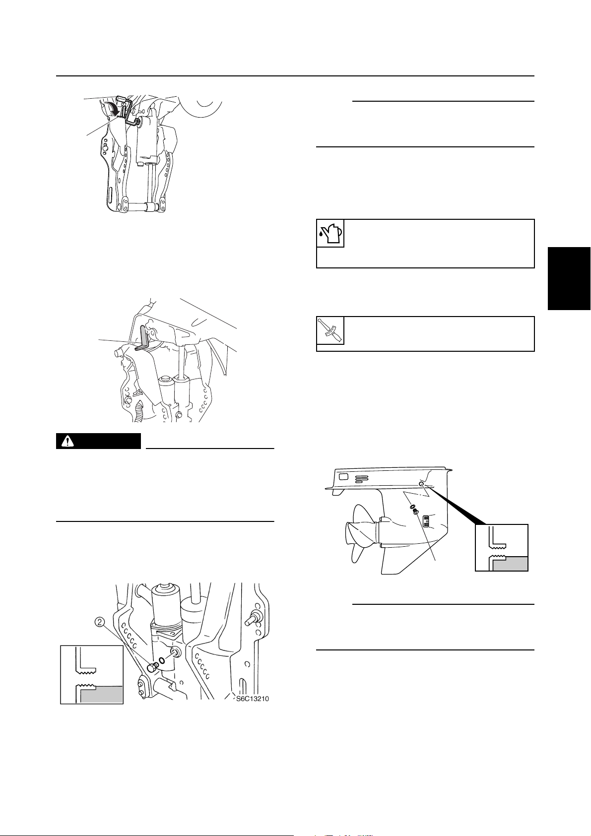
T
R
.
.
Control system / Bracket unit / Lower unit
2
1
S6C13360
Checking the power trim and tilt fluid
level
1. Fully tilt the outboard motor up, and then
support it with the tilt stop lever 1.
1
S6C13300
WARNING
After tilting up the outboard motor, be
sure to support it with the tilt stop lever.
Otherwise, the outboard motor could suddenly lower if the power trim and tilt unit
should lose fluid pressure.
NOTE:
If the fluid is at the correct level, the fluid
should overflow out of the filler hole when the
reservoir cap is removed.
3. If necessary, add sufficient fluid of the
recommended type until it overflows out
of the filler hole.
Recommended power trim and tilt
fluid:
ATF Dexron II
4. Install the reservoir cap, and then tighten
it to the specified torque.
Reservoir cap:
7 N·m (0.7 kgf·m, 5.2 ft·lb)
Lower unit
Checking the gear oil level
1. Fully tilt the outboard motor down.
2. Remove the check screw 1, and then
check the gear oil level in the lower case.
1
2
3
4
3
5
6
2. Remove the reservoir cap 2, and then
check the fluid level in the reservoir.
1
S60V3320
NOTE:
If the oil is at the correct level, the oil should
overflow out of the check hole when the
check screw is removed.
7
8
9
6C13G11
3-14
Page 64
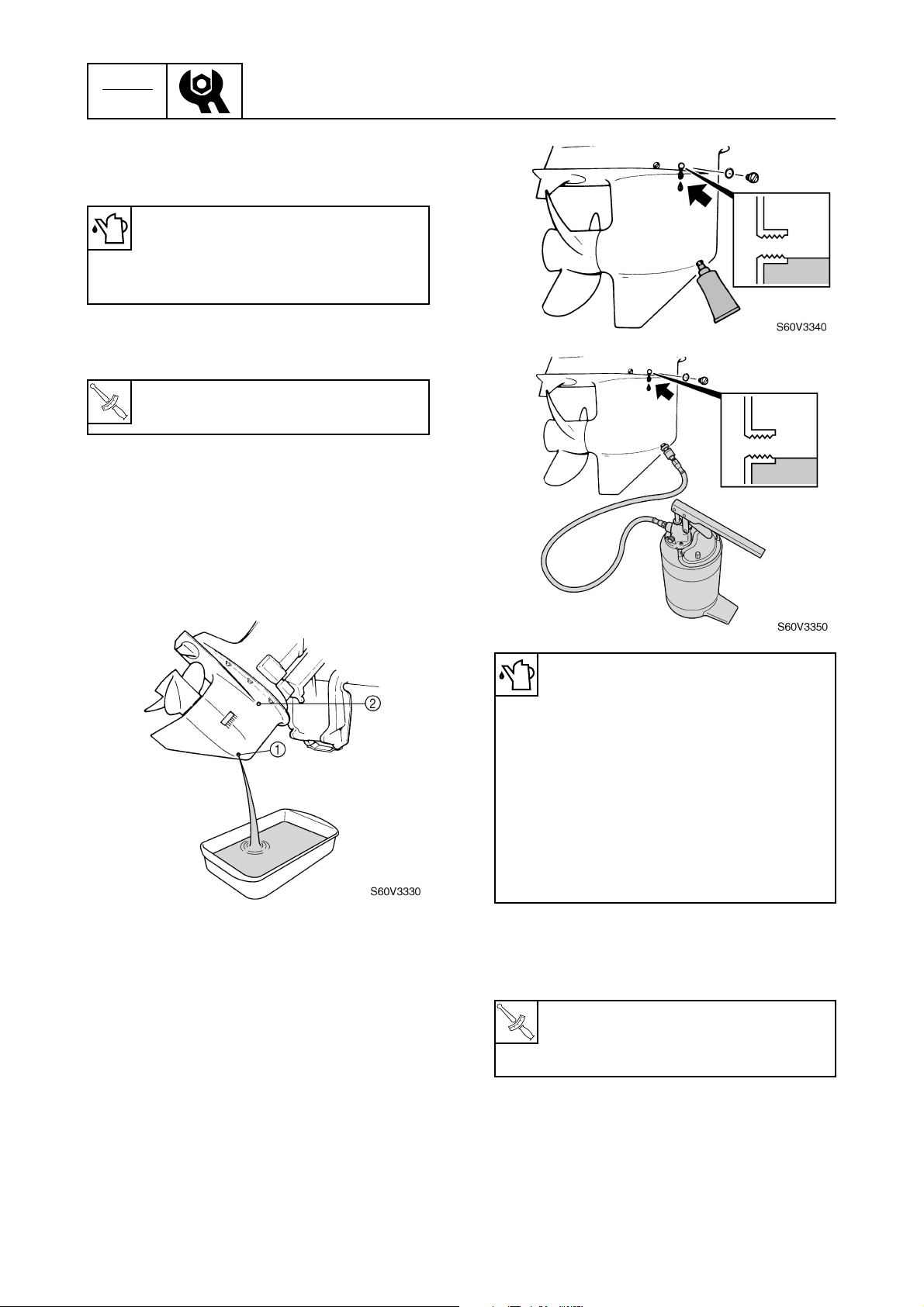
CHK
T
R
.
.
ADJ
3. If necessary, add sufficient gear oil of the
recommended type until it overflows out
of the check hole.
Recommended gear oil:
Hypoid gear oil
API: GL-4
SAE: 90
4. Install the check screw, and then tighten
it to the specified torque.
Gear oil check screw:
T
.
R
.
9 N·m (0.9 kgf·m, 6.6 ft·lb)
Changing the gear oil
1. Tilt the outboard motor up slightly.
2. Place a drain pan under the drain screw
1
, remove the drain screw, then the
check screw 2 and let the oil drain completely.
Periodic checks and adjustments
3. Check the oil for metal and discoloration,
and its viscosity. Check the internal parts
of the lower case if necessary.
4. Insert a gear oil tube or gear oil pump
into the drain hole and slowly fill the gear
oil until oil flows out of the check hole and
no air bubbles are visible.
Recommended gear oil:
Hypoid gear oil
API: GL-4
SAE: 90
Gear oil quantity:
F50, F60:
430 cm
3
(14.5 US oz, 15.2 Imp oz)
FT50, FT60:
670 cm
3
(22.7 US oz, 23.6 Imp oz)
5. Install the check screw and quickly install
the drain screw, and then tighten them to
the specified torque.
Gear oil check screw and drain
screw:
9 N·m (0.9 kgf·m, 6.6 ft·lb)
Checking the lower unit for air
leakage
1. Remove the check screw 1, and then
install the special service tool.
3-15
6C13G11
Page 65

Lower unit / General
Leakage tester: 90890-06840
2. Apply the specified pressure to check
that the pressure is maintained in the
lower unit for at least 10 seconds.
CAUTION:
Do not over pressurize the lower unit, otherwise the oil seals can be damaged.
General
Checking the anodes
1. Check the anodes and trim tab for
scales, grease, or oil. Clean if necessary.
È
3
1
2
3
4
NOTE:
Cover the check hole with a rag when removing the tester from the lower unit.
Lower unit holding pressure:
100 kPa (1.0 kgf/cm
3. If pressure drops below specification,
check the drive shaft and propeller shaft
oil seals for damage.
Checking the propeller
1. Check the propeller blades and splines
for cracks, damage, or wear. Replace if
necessary.
2
, 14.5 psi)
É
Ê
5
6
S6C13240
7
8
S6C13250
6C13G11
9
3-16
Page 66

CHK
ADJ
Periodic checks and adjustments
Ë
S60C3640
Power trim and tilt model
È
Hydro tilt model
É
F50, F60
Ê
FT50, FT60
Ë
CAUTION:
Do not oil, grease, or paint the anodes or
the trim tab, otherwise they will be ineffective.
NOTE:
If it is necessary to disassemble the outboard
motor to check an anode, refer to the applicable disassembly procedure in this manual.
2. Replace the anodes or trim tab if excessively eroded.
Checking the battery
1. Check the battery electrolyte level. If the
level is at or below the minimum level
mark a, add distilled water until the level
is between the maximum and minimum
level marks.
a
WARNING
Battery electrolyte is dangerous; it contains sulfuric acid which is poisonous and
highly caustic.
Always follow these preventive measures:
• Avoid bodily contact with electrolyte as
it can cause severe burns or permanent
eye injury.
• Wear protective eye gear when handling
or working near batteries.
Antidote (EXTERNAL):
• SKIN – Wash with water.
• EYES – Flush with water for 15 minutes
and get immediate medical attention.
Antidote (INTERNAL):
• Drink large quantities of water or milk
followed with milk of magnesia, beaten
egg, or vegetable oil. Get immediate
medical attention.
Batteries generate explosive, hydrogen
gas. Always follow these preventive measures:
• Charge batteries in a well-ventilated
area.
• Keep batteries away from fire, sparks or
open flames (e.g., welding equipment,
lighted cigarettes).
• DO NOT SMOKE when charging or handling batteries.
KEEP BATTERIES AND ELECTROLYTE
OUT OF REACH OF CHILDREN.
NOTE:
• Batteries vary per manufacturer. The procedures mentioned in this manual may not
always apply, therefore, consult the instruction manual of the battery.
• Disconnect the negative battery lead first,
then the positive battery lead.
S69J3620
2. Check the specific gravity of the electrolyte. Fully charge the battery if out of
specification.
3-17
Electrolyte specific gravity:
1.280 at 20 °C (68 °F)
6C13G11
Page 67
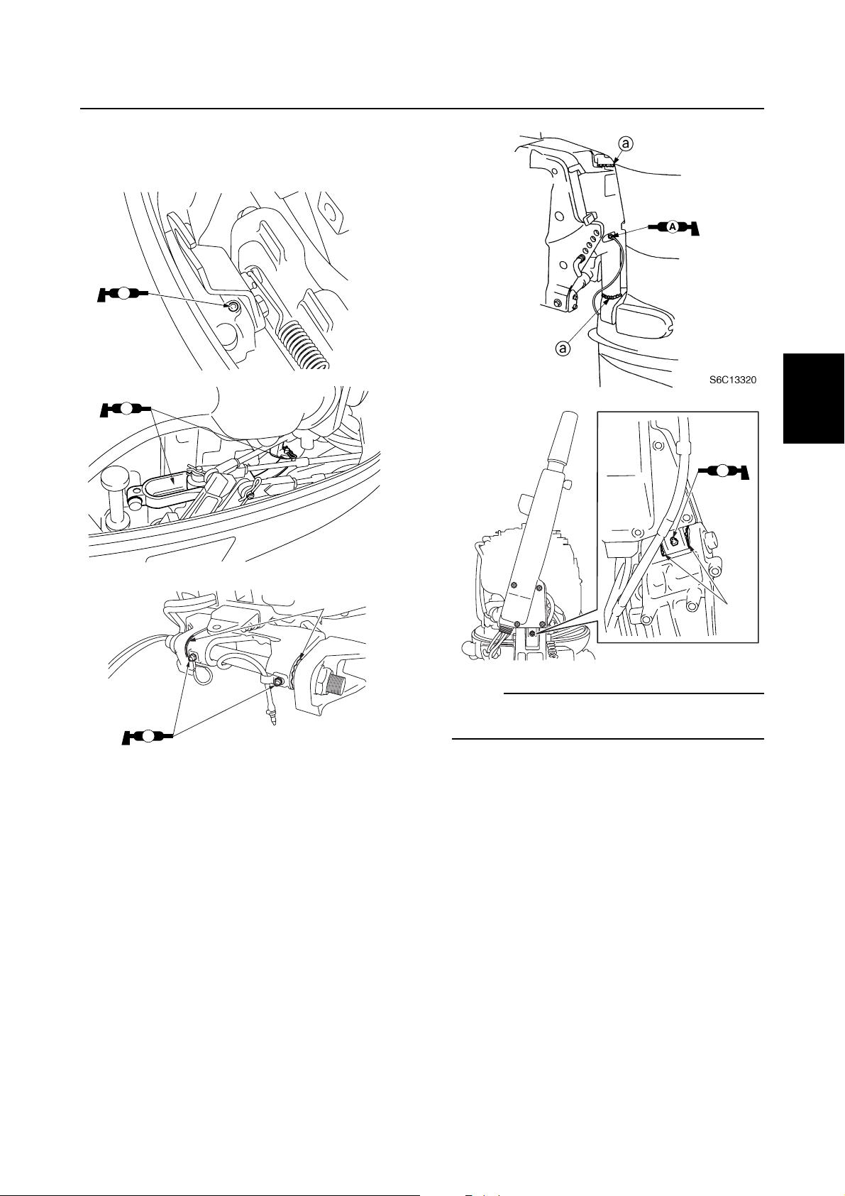
Lubricating the outboard motor
1. Apply water resistant grease to the areas
shown.
AA
S6C13270
General
1
2
AA
É
3
AA
4
S6C13290
a
NOTE:
Apply grease to the grease nipple until it
AA
S6C17360
flows from the bushings a.
a
S6C17540
5
6
7
6C13G11
8
9
3-18
Page 68

CHK
ADJ
2. Apply low temperature resistant grease
to the area shown.
3. Apply corrosion resistant grease to the
area shown.
Periodic checks and adjustments
C
S6C13280
3-19
6C13G11
Page 69

FUEL
Fuel system
Special service tools .....................................................................................4-1
Hose routing...................................................................................................4-2
Fuel and blowby hoses..............................................................................4-2
Cooling water pilot hoses ..........................................................................4-3
Fuel filter and fuel pump ...............................................................................4-4
Checking the fuel pump.............................................................................4-6
Disassembling the fuel pump ....................................................................4-6
Checking the diaphragm and valves .........................................................4-7
Assembling the fuel pump .........................................................................4-7
Checking the fuel joint ...............................................................................4-7
Intake manifold...............................................................................................4-8
Checking the throttle position sensor ......................................................4-11
Installing the throttle position sensor .......................................................4-11
Checking the idle speed control ..............................................................4-11
Vapor separator............................................................................................4-12
Disconnecting the quick connector..........................................................4-16
Measuring the fuel pressure ....................................................................4-16
Checking the pressure regulator .............................................................4-17
Draining the fuel ......................................................................................4-18
Disassembling the vapor separator .........................................................4-18
Checking the vapor separator .................................................................4-19
Adjusting the float ....................................................................................4-19
Assembling the vapor separator..............................................................4-20
1
2
3
4
5
6
6C13G11
7
8
9
Page 70

FUEL
Fuel system
Special service tools
Vacuum/pressure pump gauge set
90890-06756
Fuel pressure gauge
90890-06786
4
Fuel pressure gauge adapter B
90890-06942
4-1
6C13G11
Page 71
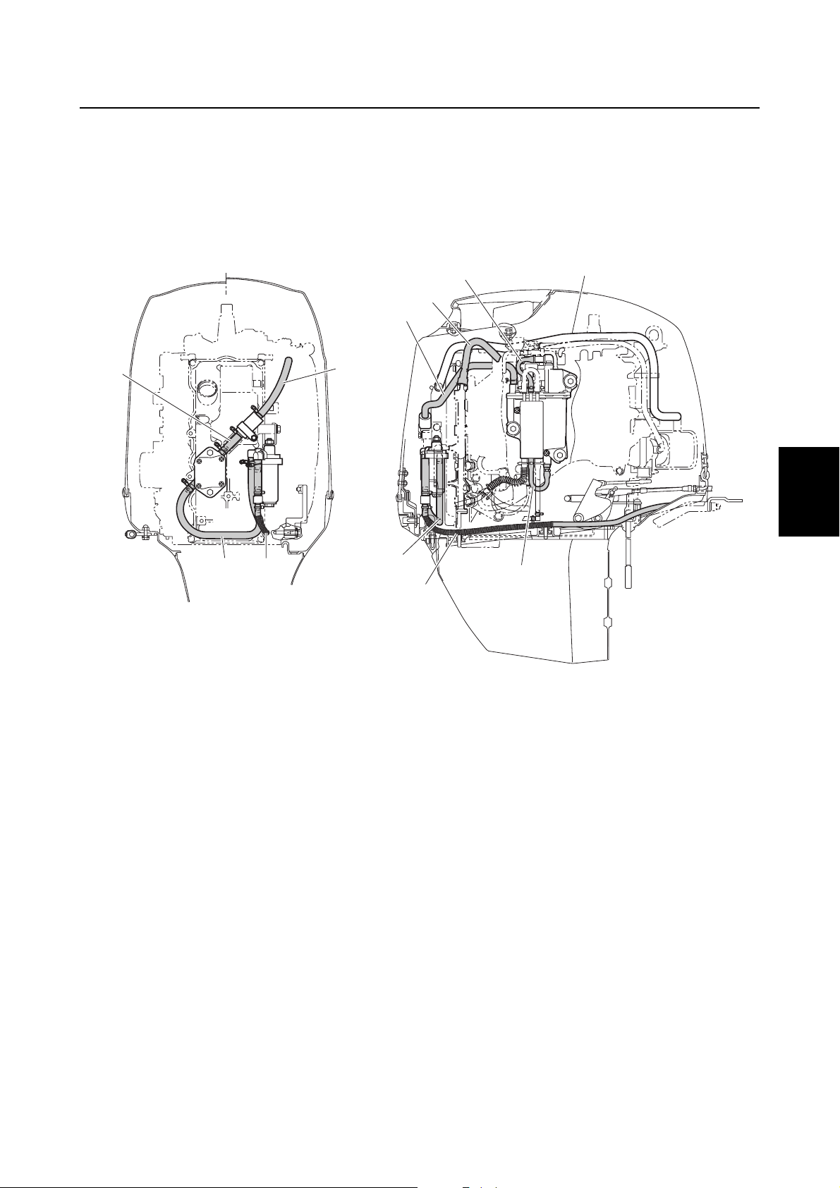
Special service tools / Hose routing
Hose routing
Fuel and blowby hoses
4
5
5
6
7
4
1
1
2
3
4
3
2
Blowby hose
1
Fuel hose (fuel joint-to-fuel filter)
2
Fuel hose (fuel filter-to-fuel pump)
3
Fuel hose (fuel pump-to-strainer)
4
Fuel hose (strainer-to-vapor separator)
5
High-pressure fuel hose (vapor separator-to-fuel rail)
6
Fuel hose (pressure regulator-to-fuel cooler)
7
Fuel hose (fuel cooler-to-vapor separator)
8
3
2
8
S6C14010
5
6
7
8
6C13G11
9
4-2
Page 72

FUEL
Fuel system
Cooling water pilot hoses
1
6
3
4
2
5
4
Cooling water pilot hose (fuel cooler to fuel cooler)
1
Cooling water pilot hose (fuel cooler to fuel joint)
2
Cooling water pilot hose (fuel joint to upper case)
3
Flushing hose (hose joint to fuel joint)
4
Cooling water pilot hose (fuel joint to water outlet joint)
5
Cooling water pilot hose (fuel cooler to fuel joint)
6
Cooling water pilot hose (water outlet joint to water outlet)
7
Cooling water pilot hose (water outlet joint to exhaust cover)
8
3
6
5
7
8
S6C14340
4-3
6C13G11
Page 73

Hose routing / Fuel filter and fuel pump
Fuel filter and fuel pump
17
5
4
7
3
17
17
2
17
4
1
9
10
8
2
3
12
13
14
15
6
11
4
1
2
T
3 N
m (0.3 kgf
.
·
R
No. Part name Q’ty Remarks
1 Fuel pump assembly 1
2Bolt 2 M6 × 30 mm
3 Fuel hose 1
4 Holder 1
5Strainer 1
6O-ring 1
7Screw 1 ø6 × 14 mm
8Bolt 1 M8 × 16 mm
9Nut 1
10 Bracket 1
11 Fuel filter assembly 1
12 O-ring 1
13 Fuel filter element 1
14 O-ring 1
15 Float 1
16 Cup 1
17 Clamp 4
Not reusable
Not reusable
Not reusable
m, 2.2 ft
·
16
Ib)
·
S6C14320
5
6
7
8
9
6C13G11
4-4
Page 74

FUEL
Fuel system
4
No. Part name Q’ty Remarks
1Screw 4 ø5 × 43 mm
2 Cover 1
3Seal 1
Not reusable
4 Fuel pump body 2 assembly 1
5 Diaphragm 1
6Pin 1
7Spring 1
8 Fuel pump body 1 1
9Nut 4
10 Spring 1
11 Plunger 1
12 Spring washer 4
4-5
6C13G11
Page 75

Checking the fuel pump
1. Disconnect the fuel hoses from the fuel
pump.
2. Connect the special service tool to the
fuel pump inlet.
3. Cover the fuel pump outlet with a finger,
and then apply the specified positive
pressure. Check that there is no air leakage.
Fuel filter and fuel pump
1
S6C14070
2
NOTE:
Assemble the fuel pump valve to the fuel
pump body, and moisten the inside of the fuel
pump with gasoline to ensure a good seal.
3
S6C14050
Vacuum/pressure pump gauge set:
90890-06756
Specified pressure:
50 kPa (0.5 kgf/cm
4. Apply the specified negative pressure
and check that there is no air leakage.
2
, 7.3 psi)
Specified pressure:
50 kPa (0.5 kgf/cm
Disassembling the fuel pump
1. Disassemble the fuel pump.
2. Push down on the plunger and the diaphragm, turn fuel pump body 1
approximately 90° to a position where the
pin 2 can be removed easily, and then
remove the pin.
2
, 7.3 psi)
1
4
5
6
7
S6C14060
Specified pressure:
30 kPa (0.3 kgf/cm
5. Connect the special service tool to the
fuel pump outlet.
6. Apply the specified positive pressure and
check that there is no air leakage. Disassemble the fuel pump if necessary.
6C13G11
2
, 4.4 psi)
8
9
3. Slowly let up on the plunger and diaphragm, and then remove them.
4-6
Page 76

FUEL
Fuel system
Checking the diaphragm and valves
1. Check the diaphragm for tears and the
valves for cracks. Replace if necessary.
Assembling the fuel pump
NOTE:
Clean the parts and soak the valves and the
diaphragm in gasoline before assembly to
obtain prompt operation of the fuel pump
when starting the engine.
1. Align the plunger and diaphragm installation holes a, and then install the plunger
into the diaphragm.
2. Push down on the plunger and the diaphragm, and then install the pin 1.
Checking the fuel joint
1. Check the fuel hose connector for cracks
or damage.
2. Connect the special service tool to the
fuel hose connector outlet.
3. Apply the specified pressure to check
that the pressure is maintained for 10
seconds. Replace the fuel hose connector if necessary.
3. Turn fuel pump body 1 2 approximately
90°, and then push down on the plunger
several times to make sure that the pin
does not come out.
Vacuum/pressure pump gauge set:
90890-06756
Fuel hose connector holding
pressure:
50 kPa (0.5 kgf/cm
2
, 7.3 psi)
NOTE:
Make sure that the gasket and diaphragm are
kept in place through the assembly process.
4-7
6C13G11
Page 77
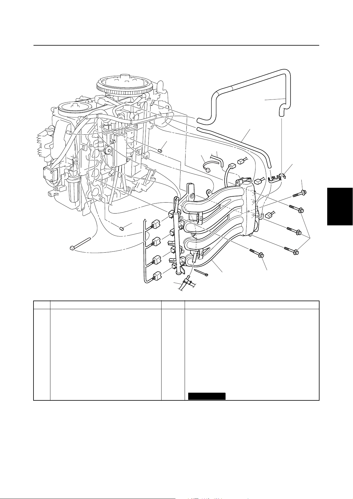
Fuel filter and fuel pump / Intake manifold
Intake manifold
10
10
11
4
1
1
3
2
9
2
4
3
4
8
No. Part name Q’ty Remarks
1 Blowby hose 1
2 Holder 1
3Hose 1
4Bolt 2 M6 × 35 mm
5Bolt 3 M6 × 45 mm
6Bolt 5 M8 × 40 mm
7 Intake manifold assembly 1
8 Cooling water pilot hose 1
9 Pressure regulator hose 1
10 Dowel 2
11 Plastic tie 1
Not reusable
7
5
5
6
S6C14100
6
7
8
6C13G11
9
4-8
Page 78

FUEL
Fuel system
4
23
T
.
R
.
1
4 N
2
m (0.4 kgf
·
21
m, 3.0 ft
·
22
Ib)
·
T
4 N
m (0.4 kgf
.
·
R
.
5
7
m, 3.0 ft
·
10
11
·
Ib)
13
4
4
3
8
9
16
6
14
15
16
12
17
19
18
T
.
R
.
9 N
m (0.9 kgf
·
m, 6.6 ft
·
Ib)
·
20
24
24
T
9 N
m (0.9 kgf
.
·
R
.
No. Part name Q’ty Remarks
1 Fuel rail 1
2Gasket 1
3 Idle speed control 1
4Screw 2 ø5 × 13 mm
5 Wiring harness 1
6O-ring 1
7Screw 2 ø5 × 13 mm
8 Sensor assembly 1
9O-ring 1
10 Collar 2
11 Grommet 2
12 Intake silencer 1
13 Screw 2
14 Throttle position sensor 1
15 O-ring 1
16 Bolt 3 M6 × 16 mm
17 Throttle body assembly 1
m, 6.6 ft
·
·
Ib)
Not reusable
Not reusable
Not reusable
Not reusable
S6C14110
4-9
6C13G11
Page 79
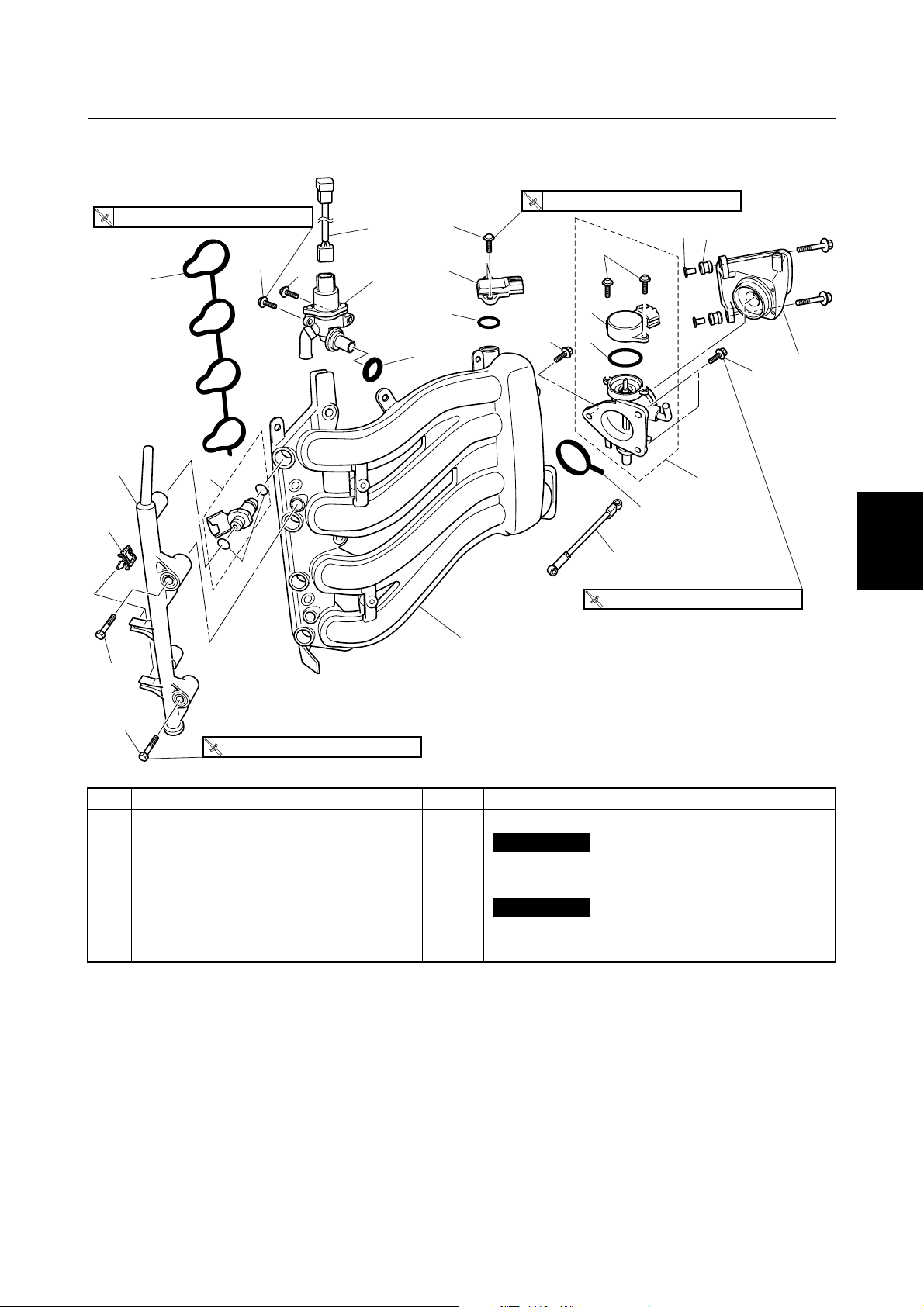
Intake manifold
4
23
24
T
.
R
.
1
4 N
2
m (0.4 kgf
·
21
m, 3.0 ft
·
22
T
4 N
m (0.4 kgf
.
·
R
16
.
13
14
15
Ib)
·
4
4
5
3
7
8
9
6
m, 3.0 ft
·
10
11
Ib)
·
16
1
2
12
3
17
19
4
20
T
.
R
.
18
9 N
m (0.9 kgf
·
m, 6.6 ft
·
Ib)
·
5
24
T
9 N
m (0.9 kgf
.
·
R
.
No. Part name Q’ty Remarks
18 Link rod 1
19 Gasket 1
20 Intake manifold 1
21 Fuel injector 4
22 O-ring set 4
23 Clip 2
24 Bolt 2 M6 × 38 mm
m, 6.6 ft
·
·
Ib)
Not reusable
Not reusable
S6C14110
6
7
8
9
6C13G11
4-10
Page 80

FUEL
Fuel system
Checking the throttle position
sensor
1. Check the throttle position sensor output
voltage using the Yamaha Diagnostic
System. If the output voltage is out of
specification, replace the throttle position sensor.
S6C14350
Throttle position sensor output
voltage at engine idle speed:
0.8–1.2 V
NOTE:
• If the throttle position sensor output voltage
is out of specification, reinstall the throttle
position sensor.
• Measure the throttle position sensor output
voltage using the Yamaha Diagnostic System.
• Do not turn the throttle stop screw a.
Checking the idle speed control
1. Check the operation of the idle speed
control using the Yamaha Diagnostic
System.
Installing the throttle position sensor
1. Install the throttle position sensor 1 in a
position where the output voltage is
within specification.
1
a
S6C14310
Throttle position sensor output
voltage at engine idle speed:
0.8–1.2 V
4-11
6C13G11
Page 81
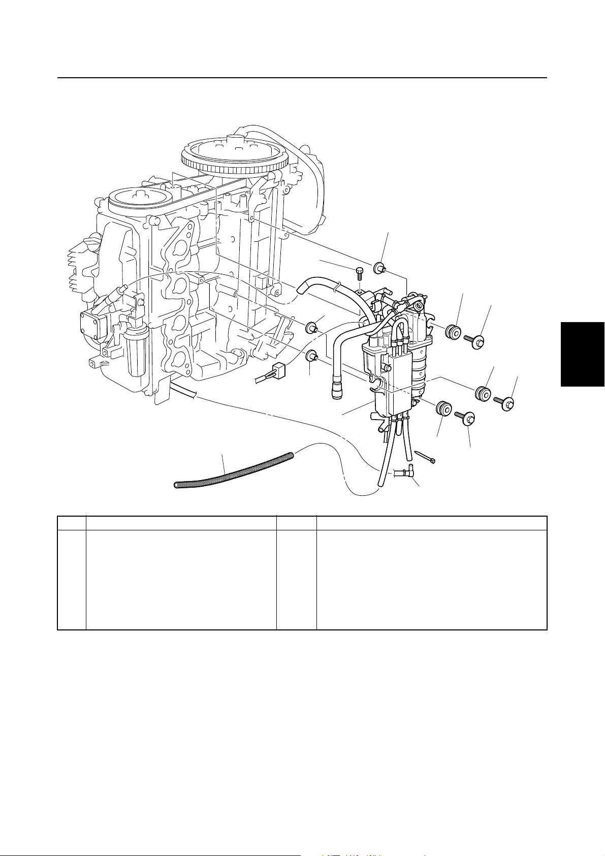
Intake manifold / Vapor separator
Vapor separator
4
1
2
6
3
4
2
3
4
2
2
3
4
1
7
No. Part name Q’ty Remarks
1 Vapor separator 1
2 Collar 3
3Grommet 3
4Bolt 3 M6 × 30 mm
5 Cooling water pilot hose 1
6Bolt 1 M6 × 15 mm
7 Corrugated tube 1
3
5
5
4
S6C14130
6
7
8
6C13G11
9
4-12
Page 82

FUEL
24
22
Fuel system
25
23
15
26
27
WATER
FUEL
WATER
14
1
28
13
4
5
7
2
3
4
6
8
9
28
21
20
19
17
12
11
16
T
3 N
.
·
R
.
T
1.5 N
.
R
.
m (0.15 kgf
·
m, 1.1 ft
·
Ib)
·
T
.
R
.
4 N
m (0.4 kgf
·
No. Part name Q’ty Remarks
1Hose 1
2 Joint 1
3Hose 1
4 Fuel hose 1
5 Holder 1
6 Fuel hose 1
7Hose 1
8Screw 6 ø5 × 14 mm
9 Cover assembly 1
10 Gasket 1
11 Hose 1
12 Hose 1
13 Screw 2 ø6 × 14 mm
14 Fuel cooler 1
15 Hose 1
16 Fuel hose 1
17 Joint screw 1
m, 3.0 ft
·
Not reusable
10
m (0.3 kgf
Ib)
·
T
3 N
.
R
.
m, 2.2 ft
·
m (0.3 kgf
·
Ib)
·
18
m, 2.2 ft
·
Ib)
·
S6C14140
4-13
6C13G11
Page 83

22
24
20
21
23
25
19
18
17
16
15
26
12
27
WATER
FUEL
WATER
11
14
1
28
13
T
.
R
.
6
3 N
2
3
28
m (0.3 kgf
·
10
5
4
T
3 N
.
R
.
m, 2.2 ft
·
m (0.3 kgf
·
Ib)
·
Vapor separator
7
8
9
m, 2.2 ft
·
·
Ib)
4
1
2
3
4
5
1.5 N
m (0.15 kgf
·
T
.
R
.
No. Part name Q’ty Remarks
18 O-ring 1
19 Drain hose 1
20 Drain screw 1
21 O-ring 1
22 Float chamber 1
23 Fuel pump damper 1
24 High-pressure fuel hose 1
25 Clamp 1
26 Hose 1
27 Solenoid valve 1
28 Clamp 2
m, 1.1 ft
·
Ib)
·
T
.
R
.
4 N
m (0.4 kgf
·
m, 3.0 ft
·
Not reusable
Not reusable
·
Ib)
S6C14140
6
7
8
9
6C13G11
4-14
Page 84

FUEL
Fuel system
4
T
.
R
.
4 N
m (0.4 kgf
·
T
5 N
.
R
.
m, 3.0 ft
·
14
m (0.5 kgf
·
Ib)
·
5
m, 3.7 ft
·
15
6
Ib)
·
3
2
4
T
m (0.2 kgf
2 N
.
1
·
R
.
m, 1.5 ft
·
·
Ib)
11
8
9
11
12
7
11
13
T
.
R
.
2 N
m (0.2 kgf
·
m, 1.5 ft
·
·
Ib)
10
16
No. Part name Q’ty Remarks
1 Cover 1
2 Pressure regulator 1
3Bolt 2 M6 × 12 mm
4O-ring 1
Not reusable
5 Joint screw 1
6O-ring 1
Not reusable
7 Electric fuel pump 1
8Grommet 1
9 Collar 1
10 Filter 1
11 Screw 2 ø4 × 6 mm
12 Wiring harness 1
13 Float 1
14 Needle valve 1
15 Pin 1
16 Clip 1
Not reusable
Not reusable
S6C14360
4-15
6C13G11
Page 85

Disconnecting the quick connector
1. Wrap the quick connector with a rag, and
then rotate the quick connector tab 1 to
the stopper position a.
a
1
2
S6C14240
WARNING
If the quick connector is removed suddenly, pressurized fuel could spray out.
To gradually release the fuel pressure, be
sure to remove the quick connector
slowly.
Vapor separator
WARNING
Always reduce the fuel pressure in the
fuel line before servicing the line or the
fuel pipe. If the fuel pressure is not
released, pressurized fuel could spray
out.
Measuring the fuel pressure
1. Disconnect the quick connector from the
fuel rail.
NOTE:
Before disconnecting the quick connector,
release the fuel pressure.
2. Connect the special service tools as
shown.
2
1
2
3
4
CAUTION:
• Do not rotate the quick connector tab
past the stopper position a, otherwise it
could be damaged.
• When the fuel hoses are disconnected,
quickly remove the retainer 2 from the
quick connector, otherwise the retainer
can be lost.
2. Disconnect the quick connector 3 from
the fuel rail 4 directly.
3
4
1
S6C14250
1
S6C14260
WARNING
• When connecting the fuel pressure
gauge, first cover the connection
between the gauge and adapter with a
clean, dry rag to prevent fuel from leaking out.
• Gently screw in the gauge until it is
firmly connected.
Fuel pressure gauge 1:
90890-06786
Fuel pressure gauge adapter B 2:
90890-06942
5
6
7
8
9
6C13G11
4-16
Page 86

FUEL
Fuel system
3. Turn the engine start switch to ON, and
then measure the fuel pressure within 3
seconds.
WARNING
Before measuring the fuel pressure, make
sure that the drain screw is tightened
securely.
NOTE:
The fuel pressure decreases 3 seconds after
the engine start switch is turned to ON.
Fuel pressure (reference data):
2
290 kPa (2.9 kgf/cm
, 41.2 psi)
4. Start the engine, warm it up for 5 minutes, and then measure the fuel pressure. If below specification, check the
high-pressure fuel line and the vapor
separator.
WARNING
• Do not loosen the drain screw while
measuring the fuel pressure. Loosening
the drain screw can cause fuel to spray
out creating a fire hazard.
• After measuring the fuel pressure, cover
the end of the hose with a clean, dry rag,
point the hose downward, and then
loosen the drain screw to drain the
remaining fuel from the hose and gauge.
• When storing the fuel pressure gauge,
make sure that the drain screw is tightened securely.
NOTE:
Before disconnecting the quick connector,
release the fuel pressure.
3. Connect the special service tools as
shown.
4. Disconnect the pressure regulator hose,
and then connect the special service
tools to the pressure regulator.
S6C14160
WARNING
• When connecting the fuel pressure
gauge, first cover the connection
between the gauge and adapter with a
clean, dry rag to prevent fuel from leaking out.
• Gently screw in the gauge until it is
firmly connected.
Fuel pressure gauge: 90890-06786
Vacuum/pressure pump gauge set:
90890-06756
Fuel pressure gauge adapter B:
90890-06942
Fuel pressure (reference data):
230 kPa (2.3 kgf/cm
2
, 32.7 psi)
Checking the pressure regulator
1. Remove the cap.
2. Disconnect the quick connector from the
fuel rail.
4-17
5. Start the engine and let it idle.
6. Check that the fuel pressure reduces
when vacuum pressure is applied to the
pressure regulator. If the fuel pressure
does not reduce, replace the pressure
regulator.
6C13G11
Page 87

WARNING
• Before measuring the fuel pressure,
make sure that the drain screw is tightened securely.
• Do not loosen the drain screw while
measuring the fuel pressure. Loosening
the drain screw can cause fuel to spray
out creating a fire hazard.
• After measuring the fuel pressure, cover
the end of the hose with a clean, dry rag,
point the hose downward, and then
loosen the drain screw to drain the
remaining fuel from the hose and gauge.
• When storing the fuel pressure gauge,
make sure that the drain screw is tightened securely.
Draining the fuel
1. Remove the cap 1.
Vapor separator
4. Drain the fuel from the vapor separator
drain hose by pressing the valve using a
thin screwdriver.
2
2
S6C14190
Disassembling the vapor separator
1. Remove the cap 1.
2. Cover the valve a of the vapor separator
with a rag, and then press in the valve
using a thin screwdriver to release the
fuel pressure.
a
1
2
3
4
2. Cover the valve a of the vapor separator
with a rag, and then press in the valve
using a thin screwdriver to release the
fuel pressure.
1
a
WARNING
Always reduce the fuel pressure in the
high-pressure fuel line before servicing
the line or the vapor separator. If the fuel
pressure is not released, pressurized fuel
may spray out.
a
S6C14180
1
a
3. Remove the float chamber.
4. Remove the float pin and float.
b
S6C14180
5
6
7
8
3. Place a container under the vapor separator drain hose, and then loosen the
drain screw 2.
6C13G11
S6C14220
9
NOTE:
Remove the float pin in the direction of the
arrow b shown.
4-18
Page 88

FUEL
Fuel system
5. Remove the needle valve and other components.
Checking the vapor separator
1. Check the needle valve for bends or
wear. Replace if necessary.
Float height c:
46.6 ± 1.0 mm (1.83 ± 0.04 in)
S6D54200
2. Check the float for deterioration. Replace
if necessary.
3. Check the filter for dirt or residue. Clean
if necessary.
4. Install the needle valve, float, and float
pin, and then check the float for smooth
operation.
a
b
S6C14210
NOTE:
• Do not reuse the float pin, always replace it
with a new one.
• Install the float pin in the direction of the
arrow a shown.
• Install the float pin with its tapered end
towards the punch mark b on the vapor
separator cover.
6. Check the float height
d
as shown.
Adjust the float height if out of specification.
d
S6C14200
NOTE:
The float should be resting on the needle
valve, but not compressing it.
Float height d:
35.0 ± 1.0 mm (1.38 ± 0.04 in)
Adjusting the float
1. Adjust the stopper a of the float by
bending it until the float height b is within
specification.
5. Check the float height c as shown.
Adjust the float height if out of specification.
4-19
6C13G11
Page 89
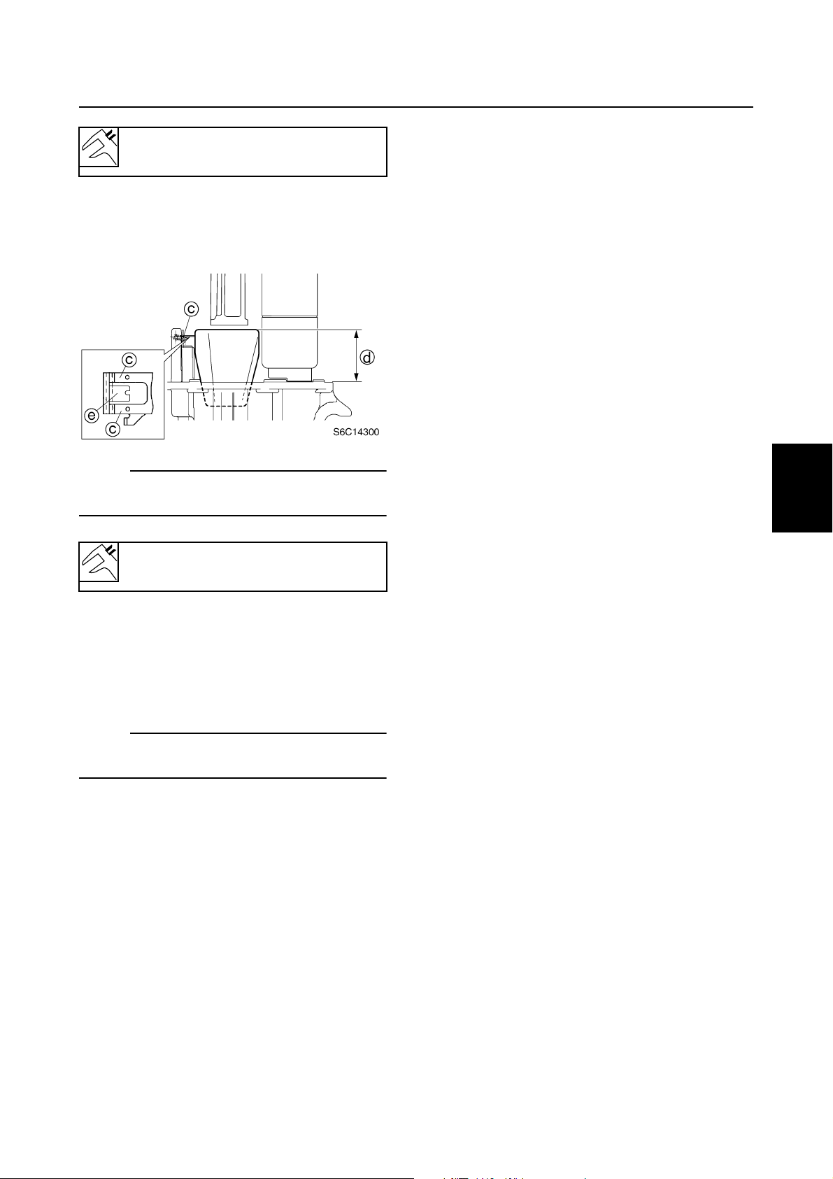
Float height b:
46.6 ± 1.0 mm (1.83 ± 0.04 in)
2. Adjust the lever c of the float by bending
it until the float height d is within specification.
NOTE:
When adjusting the float height, do not bend
the lever e.
Vapor separator
1
2
3
4
Float height d:
35.0 ± 1.0 mm (1.38 ± 0.04 in)
Assembling the vapor separator
1. Install the float chamber.
2. Install all parts removed during dissasembly.
NOTE:
Be sure to connect and route the hoses correctly.
5
6
7
8
6C13G11
9
4-20
Page 90

POWR
Power unit
Special service tools .....................................................................................5-1
Power unit.......................................................................................................5-3
Checking the compression pressure .........................................................5-3
Checking the oil pressure ..........................................................................5-3
Checking the valve clearance....................................................................5-4
Removing the power unit.........................................................................5-14
Removing the timing belt and sprockets..................................................5-15
Checking the timing belt and sprockets...................................................5-16
Installing the timing belt and sprockets....................................................5-17
Cylinder head ...............................................................................................5-19
Removing the cylinder head ....................................................................5-23
Checking the valve springs......................................................................5-24
Checking the valves ................................................................................5-24
Checking the valve guides.......................................................................5-25
Replacing the valve guides......................................................................5-25
Checking the valve seat ..........................................................................5-26
Refacing the valve seat ...........................................................................5-27
Checking the rocker arms and rocker arm shaft......................................5-29
Checking the camshaft ............................................................................5-29
Checking the cylinder head .....................................................................5-30
Checking the oil pump .............................................................................5-31
Installing the valves .................................................................................5-31
Installing the camshaft.............................................................................5-32
Installing the rocker arm shaft assembly .................................................5-32
Installing the oil pump..............................................................................5-33
Installing the cylinder head ......................................................................5-34
Exhaust cover ..............................................................................................5-35
6C13G11
Page 91

Cylinder block ..............................................................................................5-37
Disassembling the cylinder block ............................................................5-38
Checking the piston diameter ..................................................................5-39
Checking the cylinder bore ......................................................................5-39
Checking the piston clearance ................................................................5-39
Checking the piston rings ........................................................................5-39
Checking the piston ring grooves ............................................................5-40
Checking the piston ring side clearance..................................................5-41
Checking the piston pin boss bore ..........................................................5-41
Checking the piston pin ...........................................................................5-41
Checking the connecting rod small end inside diameter ......................... 5-41
Checking the connecting rod big end side clearance..............................5-41
Checking the crankshaft ..........................................................................5-42
Checking the crankpin oil clearance........................................................5-42
Selecting the connecting rod bearing ......................................................5-43
Checking the crankshaft journal oil clearance .........................................5-44
Selecting the main bearings ....................................................................5-45
Assembling the power unit ......................................................................5-46
Installing the power unit...........................................................................5-49
1
2
3
4
5
6
7
8
9
6C13G11
Page 92

POWR
Power unit
Special service tools
Compression gauge
90890-03160
Flywheel holder
90890-06522
5
Valve spring compressor attachment
90890-06320
Valve guide remover/installer
90890-06801
Flywheel puller
90890-06521
Crankshaft holder 18
90890-06562
Valve spring compressor
90890-04019
Valve guide installer
90890-06810
Valve guide reamer
90890-06804
Valve seat cutter holder
90890-06316
5-1
6C13G11
Page 93
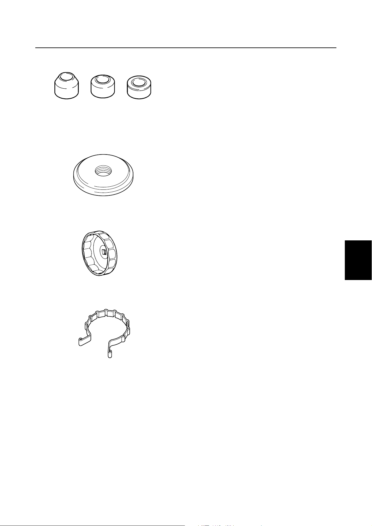
Valve seat cutter
90890-06312, 90890-06315, 90890-06323,
90890-06327, 90890-06328, 90890-06555
Bearing outer race attachment
90890-06626
Special service tools
1
2
3
Oil filter wrench
90890-01426
Piston slider
90890-06529
4
5
6
7
8
6C13G11
9
5-2
Page 94
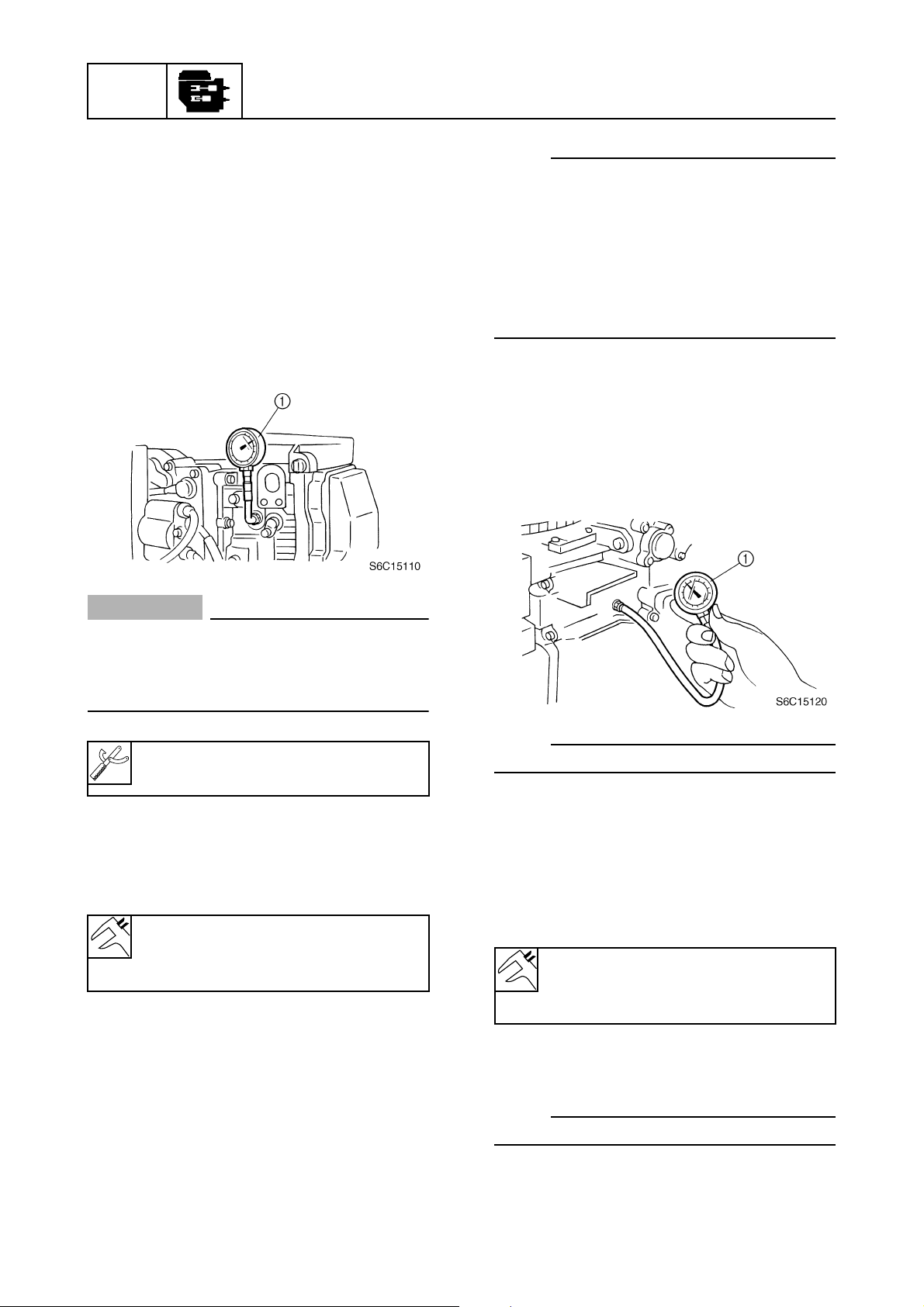
POWR
Power unit
Power unit
Checking the compression pressure
1. Start the engine, warm it up for 5 minutes, and then turn it off.
2. Remove the clip from the engine stop
lanyard switch.
3. Remove the spark plug caps and all
spark plugs, and then install the special
service tools into a spark plug hole.
5
NOTE:
• If the compression pressure increases,
check the pistons and piston rings for wear.
Replace if necessary.
• If the compression pressure does not
increase, check the valve clearance,
valves, valve seat, cylinder sleeve, cylinder
head gasket, and cylinder head. Adjust or
replace if necessary.
Checking the oil pressure
1. Place a rag under the oil pressure switch.
2. Remove the oil pressure switch, and then
install an oil pressure gauge 1 into the
oil pressure switch installation hole.
CAUTION:
Before removing the spark plugs, blow
compressed air in the spark plug well to
clear out any dirt or dust that may fall into
the cylinder.
Compression gauge 1:
90890-03160
4. Fully open the throttle, crank the engine
until the reading on the compression
gauge stabilizes, and then check the
compression pressure.
Minimum compression pressure
(reference data):
960 kPa (9.6 kgf/cm
5. If the compression pressure is below
specification and the compression pressure for each cylinder is unbalanced, add
a small amount of engine oil to the cylinder, and then check the pressure again.
2
, 139.2 psi)
NOTE:
Use a general pressure gauge.
3. Start the engine and warm it up for 5 minutes.
4. Check the oil pressure. Check the oil
pump and oil strainer and check for oil
leakage if below specification.
Oil pressure (reference data):
125 kPa (1.25 kgf/cm
2
, 18.1 psi)
at engine idle speed
5. Increase the engine speed, and then
check the relief valve opening pressure.
NOTE:
The relief valve is installed in the oil pump.
5-3
6C13G11
Page 95

Relief valve opening pressure
(reference data):
350–450 kPa
(3.5–4.5 kgf/cm
Checking the valve clearance
CAUTION:
Do not turn the flywheel magnet counterclockwise, otherwise the valve system
may be damaged.
1. Remove the flywheel magnet cover, and
then remove the blowby hose 1.
2. Remove the fuel pump 2 and fuel filter
3
.
2
, 50.8–62.3 psi)
Power unit
c
a
b
S6C15140
1
2
3
3. Disconnect the spark plug caps and
remove the spark plugs and cylinder
head cover 4.
4
4. Turn the flywheel magnet clockwise and
align the “ 1” mark a on the driven
sprocket with the “” mark b on the cylinder head.
1
3
2
S6C15130
5. Check the intake valve clearance for cylinders #1 and #2, and the exhaust valve
clearance for cylinders #1 and #3. Adjust
if out of specification.
6. Turn the flywheel magnet clockwise and
align the “ 4” mark c on the driven
sprocket with the “” mark b on the cylinder head.
4
5
6
7
8
6C13G11
9
5-4
Page 96

POWR
T
R
.
.
Power unit
7. Check the intake valve clearance for cylinders #3 and #4, and the exhaust valve
clearance for cylinders #2 and #4. Adjust
if out of specification.
EX IN
#1
#2
#3
#4
d
e
NOTE:
• To decrease the valve clearance, turn the
adjusting screw clockwise.
• To increase the valve clearance, turn the
adjusting screw counterclockwise.
9. Tighten the rocker arm locknut to the
specified torque, and then check the
valve clearance again. Adjust if necessary.
Rocker arm locknut 5:
14 N·m (1.4 kgf·m, 10.3 ft·lb)
10. Install the cylinder head cover, fuel
pump, fuel filter, spark plugs, spark plug
caps, blowby hose, and flywheel magnet
cover.
S6C15150
NOTE:
Check the valve clearance when the engine
is cold.
Valve clearance (cold):
Intake d:
0.20 ± 0.05 mm
(0.008 ± 0.002 in)
Exhaust e:
0.30 ± 0.05 mm
(0.012 ± 0.002 in)
8. Loosen the rocker arm locknut 5, and
then turn the adjusting screw 6 until the
specified valve clearance is obtained.
5
6
S6C15160
5-5
6C13G11
Page 97
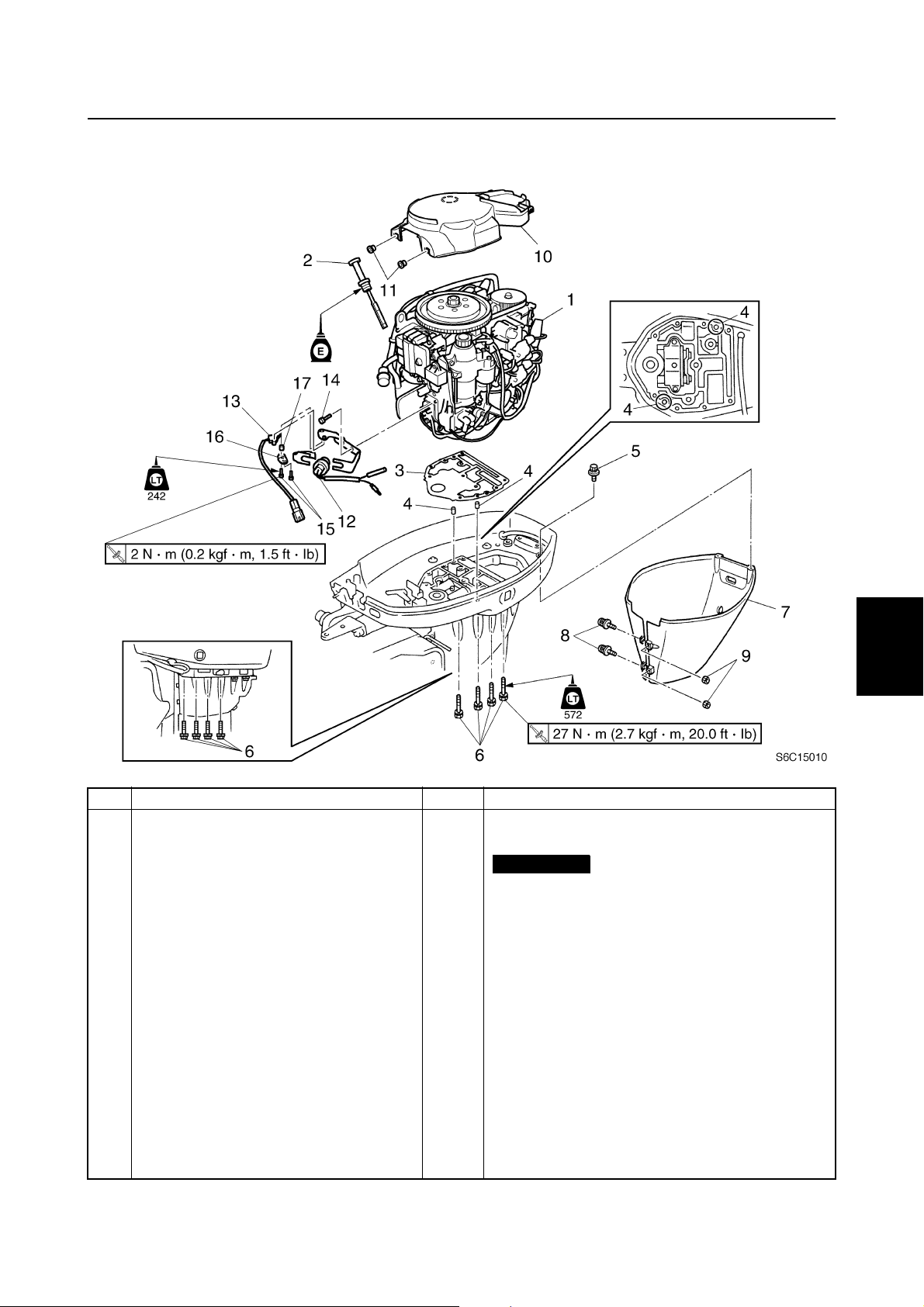
Power unit
5
1
2
3
No. Part name Q’ty Remarks
1 Power unit 1
2 Oil dipstick 1
3Gasket 1
4 Dowel 2
5Bolt 2 M6 × 16 mm
6Bolt 8 M8 × 80 mm
7 Apron 1
8Screw 2 ø6 × 24 mm
9Nut 2
10 Flywheel magnet cover 1
11 Grommet 2
12 Neutral switch 1 Tiller handle model
13 Shift position switch 1
14 Bolt 2 M6 × 20 mm
15 Screw 2 ø4 × 16 mm
16 Plate 1
17 Collar 1
Not reusable
4
5
6
7
8
9
6C13G11
5-6
Page 98

POWR
Power unit
5
No. Part name Q’ty Remarks
1Nut 1
2 Washer 1
3 Flywheel magnet 1
4Bolt 3 M6 × 30 mm
5 Stator coil 1
6 Stator coil bracket 1
7Bolt 4 M6 × 30 mm
8 Collar 2
9 Pulser coil 1
10 Bolt 2 M5 × 12 mm
11 Woodruff key 1
12 Bolt 1 M6 × 20 mm
5-7
6C13G11
Page 99

Power unit
5
1
2
3
No. Part name Q’ty Remarks
1 Timing belt 1
2 Nut 1 Width across flats: 41 mm (1.6 in)
3 Retaining plate 1
4 Drive sprocket 1
5 Bolt 1 M10 × 35 mm
6 Washer 1
7 Driven sprocket 1
8 Dowel 1
9 Woodruff key 1
4
5
6
7
8
6C13G11
9
5-8
Page 100

POWR
10
Power unit
5
7
6
8
9
3
7
5
12
T
7 N
m (0.7 kgf
.
·
R
.
No. Part name Q’ty Remarks
1 Rectifier Regulator 1
2Bolt 2 M6 × 25 mm
3 Spark plug 4
4 Spark plug wire 4
5 Holder 1
6 Ignition coil 2
7Bolt 4 M6 × 30 mm
8 Holder 2
9Bracket 1
10 Bracket 1
11 Cover 1
12 Holder 1
m, 5.2 ft
·
·
Ib)
T
.
R
.
17 N
m (1.7 kgf
·
m, 12.5 ft
·
4
2
Ib)
·
1
2
11
S6C15050
5-9
6C13G11
 Loading...