

G-1000DXC
G-2800DXC
Antenna Rotator & Controller
User Manual
EnglishEspañolDeutschFrançaisItaliano
VERTEX STANDARD CO., LTD.
4-8-8 Nakameguro, Meguro-Ku, Tokyo 153-8644, Japan
VERTEX STANDARD
US Headquarters
17210 Edwards Rd., Cerritos, CA 90703, U.S.A.
International Division
8350 N.W. 52nd Terrace, Suite 201, Miami, FL 33166, U.S.A.
YAESU EUROPE B.V.
P.O. Box 75525, 1118 ZN Schiphol, The Netherlands
YAESU UK LTD.
Unit 12, Sun Valley Business Park, Winnall Close
Winchester, Hampshire, SO23 0LB, U.K.
YAESU GERMANY GmbH
Am Kronberger Hang 2, D-65824 Schwalbach, Germany
VERTEX STANDARD HK LTD.
Unit 5, 20/F., Seaview Centre, 139-141 Hoi Bun Road,
Kwun Tong, Kowloon, Hong Kong


G-1000DXC/G-2800DXC
Heavy-Duty Antenna Rotator & Controller
English
English
The Yaesu G-1000DXC and G-2800DXC are designed
to rotate large tower-mounted amateur and professional
antenna arrays under remote control from the station
operating position. The clamshell rotator design utilizes
100 7/16-inch dual-stacked circumferential ball bearings
to distribute load over the full diameter of the housing.
This design minimizes stress and wear, and practically
eliminates the possibility of destructive water entry: there
is no shaft hole in the top of the housing.
Instead of the usual AC motor drive used in older rotator
designs, the G-1000DXC and G-2800DXC use a variable-voltage DC motor, obviating the need for a large
starting capacitor with its potential for failure exposed
to outside temperature variations. The factory-lubricated
rotator unit is housed in melamine resin-coated die-cast
aluminum, intended to provide maintenance-free operation under all climatic conditions. A mast alignment gauge
on the rotator housing simplifies accurate mechanical
alignment during installation.
The handsome desktop controller matches the design of
modern transceivers, providing 360° radial indication of
actual antenna bearing azimuth. You can select rotating
speeds from 40 to 100 seconds per (360°) rotation (G-
1000DXC, G-2800DXC: 50 to 120 seconds per (360°)
rotation), and can preset a desired heading for the rotator, to which it then turns automatically.
features avoid sharp jolts to the antenna array and tower.
Activating the rotator causes it to begin turning at slow
speed. As the antenna approaches the desired heading
rotation automatically slows before bringing the antenna
to a gentle stop. The operator may select the stopper
heading (the bearing through which the rotator cannot
be turned) most convenient for his location and operation, allowing full rotation through north, south or both,
if desired. In any case, 90° overlapping rotation allows
rotation through the selected stopper heading (450° total rotation).
The rotator is intended for mounting inside a support
tower (not supplied), at least 1 meter from the top, with
an optional (Yaesu model GS-680U) thrust bearing
above. This kit includes one mast clamp and related hardware, plus plug connectors for both the rotator and controller to simplify installation and servicing. The G-
40MWP 40 m length Control Cable is optional.
The GS-232A Computer Control Unit is available as an
option, allowing positioning of the antenna by a personal
computer, via an RS-232 serial interface.
Please read this manual through carefully before installing the rotator, to acquaint yourself with the procedures
that will be required, and to ensure that you have all necessary items for your installation.
In the G-2800DXC model, when a fast rotating speed is
selected, special “auto slow start” and “auto slow stop”
G-1000DXC/-2800DXC User Manual Page 1
Safe and Correct Use of the Equipment
3
3
3
2
2
2
5
5
4
4
2345678901234567890123456789012123456789012
2345678901234567890123456789012123456789012
2345678901234567890123456789012123456789012
Warning
Caution
23456789012345678901234
English
23456789012345678901234
Indicates that the associated instructions must always be followed to ensure
safe operation of the equipment.
Please read this user manual thoroughly
and familiarize yourself with the correct
installation procedure before starting installation.
Installing this product requires work to be undertaken high above ground. Performing work
with which you are unfamiliar can lead to fatal
accidents due to falling.
Similarly, failing to install the product correctly
can be a cause of the antenna and associated
equipment collapsing, resulting in a fatal accident or damage to houses or other property.
Accordingly, always check all safety considerations before starting work.
Ensure that the size of the antenna attached to this product is within the specifications listed in this manual.
Attaching an antenna that is larger than allowed
by the specifications can be a cause of the antenna and associated equipment collapsing, resulting in a fatal accident or damage to houses
or other property.
234567890123456789012345678901212345678901
234567890123456789012345678901212345678901
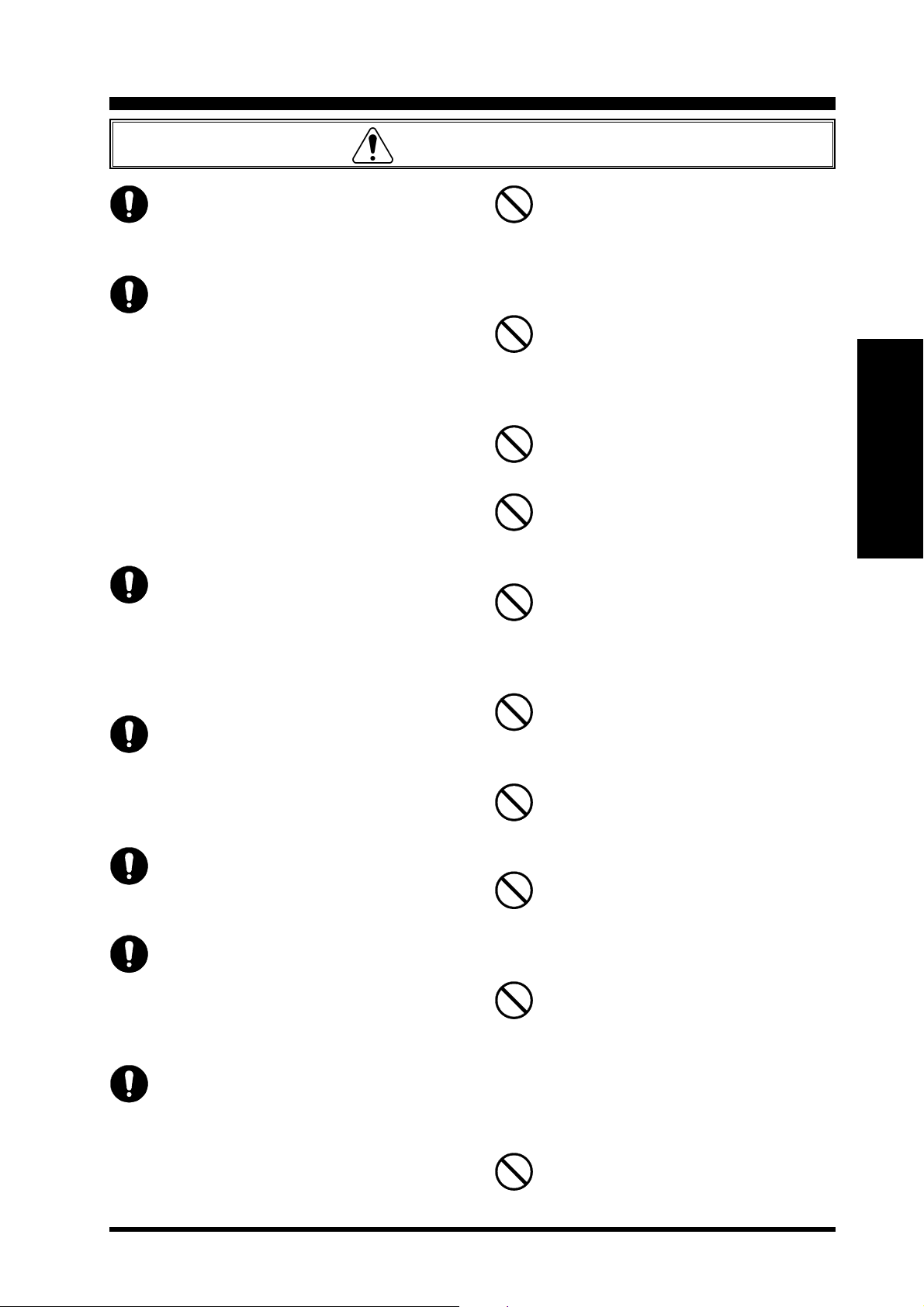
Meaning of Symbols
234567890123456789012345678901212345678901
Indicates that failure to follow the associated instructions could result
in death or serious injury.
Indicates that failure to follow the associated instructions could result
in injury or physical damage.
Meaning of Symbols Used in Diagrams
Indicates unsafe operations that should
never be performed.
Warning
When working high above ground, ensure that there are no people at ground
level.
Dropping tools, bolts, or other parts could result in death or serious injury.
Always wear a safety harness when
working high above ground.
Failure to use a safety harness can be a cause of
death or serious injury.
Ensure that the bolts and other fasteners used for installation are tightened
securely.
Failure to tighten bolts and other fasteners sufficiently can be a cause of the antenna and associated equipment collapsing, resulting in a fatal
accident or damage to houses or other property.
Never disassemble or modify the unit.
2345678901234567890123
2345678901234567890123
G-1000DXC/-2800DXC User ManualPage 2

Safe and Correct Use of the Equipment
Caution
When installing this product, take care
not to jam your fingers between parts or
cut fingers on edges of parts.
If the condition of the equipment is abnormal such as emitting smoke or an
unusual smell, continuing to use the
equipment may result in fire or malfunction.
In such cases, turn off the power immediately
and unplug from the power socket.
After checking that the equipment is no longer
emitting the smoke or unusual smell, return the
product to the vendor or to your nearest Yaesu
Musen office or service center for repair.
In the event of foreign material getting
inside the controller, turn off the power
immediately and unplug from the power
socket.
Continuing to use the product in this condition
can result in fire or malfunction.
Do not use the product with a power supply voltage other than the specified voltage as this can cause fire or electric
shock.
In the product is to remain unused for a
long period of time, unplug the AC power
cable from the AC wall outlet and Rotator Control Cable from the jack for safety.
Do not operate continuously for more
than 3 minutes.
The equipment can be operated for up to 5 minutes but operation must be halted and the motor
rested for at least 15 minutes afterwards.
There are no serviceable parts inside the
rotator or controller; therefore, never
open these units.
Do not place the controller in an unstable
position such as on an unsteady or sloping surface as this can cause the controller to fall or tip over causing injury.
Do not place heavy objects on the power
cable and do not excessively bend or
pull the cable.
Damage to the power cable can cause fire or
malfunction.
Do not place the controller in direct sunlight or close to heaters as this can cause
the box to distort or discolor.
Do not place the controller in humid or
dusty environments as this can cause
fire or malfunction.
Do not place the controller in enclosed
or poorly ventilated positions such as
in a bookshelf as this can cause fire or
faults.
Do not place the controller on carpet or
bedding as this can cause heat to build
up internally resulting in fire.
Do not place heavy objects on top of the
controller as this can cause the controller to fall or tip over causing injury.
Do not place small metal objects such
as paper clips on top of the controller as
these can fall into the controller causing fire or malfunction.
Do not wipe the controller with solvents
such as thinner or benzene as this can
cause the box to distort or discolor.
To clean the controller, gently wipe with a cloth
moistened with a neutral detergent and clean off
with a dry cloth.
English
Do not turn on the power supply until
rotator and controller setup is complete.
G-1000DXC/-2800DXC User Manual Page 3

English
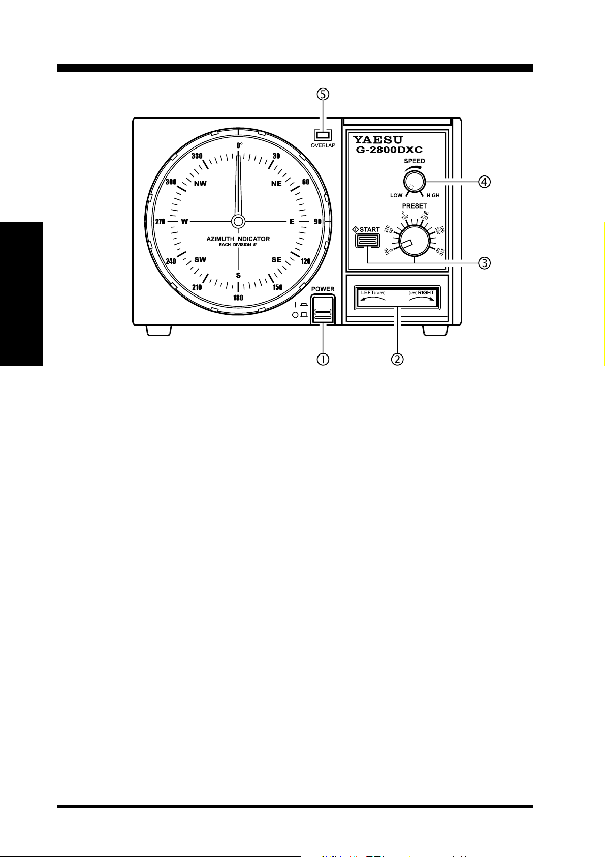
Controller Front Panel
POWER Switch
Press this switch to turn the controller on to rotate
the antenna. Turn it off when the rotator is not in
use.
LEFT/RIGHT Seesaw Switch
Press the LEFT side of this switch to rotate the antenna counter-clockwise (CCW). Press the RIGHT
side to rotate the antenna clockwise (CW).
PRESET Control and START Switch
Set the PRESET control to the desired antenna heading according to the inner angular scale (0 ~ 90)
around this control, then press the (momentary)
START switch to activate automatic rotation to the
desired heading. You can press the LEFT/RIGHT
switch to abort preset operation.
Note: If you change the rotator starting position to
the 180° (S: South), set the PRESET control to the
desired antenna heading according to the outer angular scale (180 ~ 270) around this control.
SPEED Control
Set this control for the desired rotating speed between approximately 30 and 100 seconds per 360°
revolution.
OVERLAP Indicator
This red LED glows when the antenna is rotated
beyond about 360° (to 450°) from its fully counterclockwise position. Check this indicator before rotating the antenna clockwise, and turn the antenna
counter-clockwise to the desired position if the indicator is on.
G-1000DXC/-2800DXC User ManualPage 4

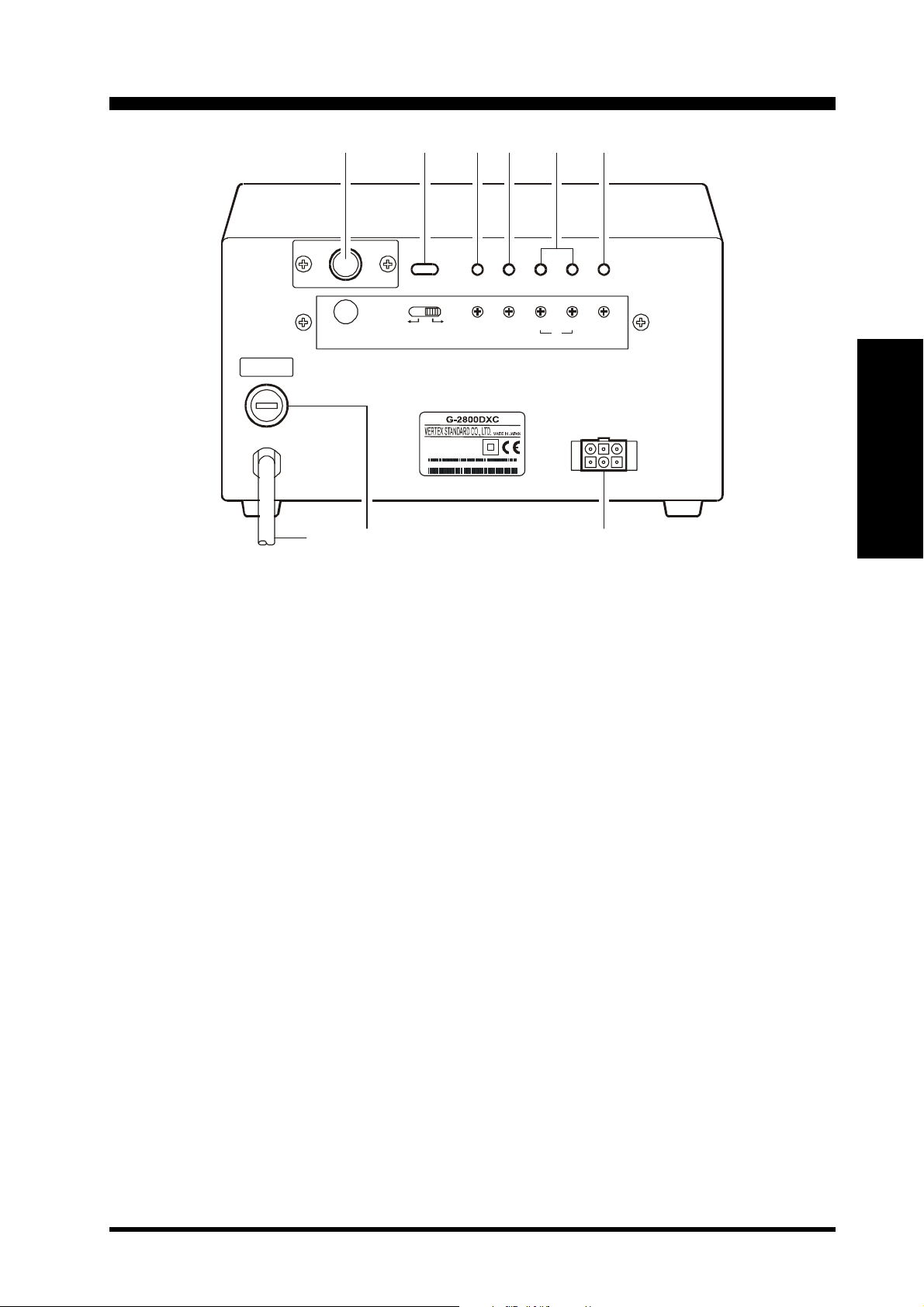
Controller Rear Panel
OPERATION
T 1A L
EXT
CONT ROL
MODE
ADJ. MO DE FULL
SELECT
SWITCH
INPUT AC22 0 - 240V ~
0.7A 50 - 60Hz
SER. NO. 000000000
SCALE
ADJ
OVERLAP
LED ADJ
AB
PRESET
ADJ
OUT VOL
ADJ
English
EXT CONTROL Connector
This 6-pin mini-DIN connector is used for connection to the optional GS-232A Computer Control
Unit.
SELECT SWITCH
Set this switch to the “ADJ. MODE” position while
calibrating the internal adjustments of the controller. During normal operation, however, set this switch
to the “OPERATION MODE” position.
FULL SCALE ADJ Potentiometer
This control calibrates the maximum rotation angle
(range) of the azimuth indicating needle to match
the maximum angle of the rotator.
OVERLAP LED ADJ Potentiometer
This control calibrates the OVERLAP Indicator to
match the azimuth indicating needle.
PRESET ADJ (A & B) Potentiometers
These controls calibrate the angle of the PRESET
control on the front panel to match the azimuth indicating needle. Pot. A should be adjusted only near
the 0° position, and Pot. B only near the 450° position.
OUT VOL ADJ Potentiometer
This control presets the voltage range at pin 4 of the
6-pin mini-DIN EXT CONTROL Connector, for
calibration of the A-to-D converter on the (optional)
GS-232A Computer Control Unit.
Rotator Control Cable Jack
The supplied control cable from the rotator connects
to this 6-pin jack.
FUSE Holder
This holder requires a 1-A fuse for AC voltage from
220 to 240V. If the fuse is blown, replace only with
a fuse of the same rating. See your Yaesu dealer for
a suitable replacement.
AC Cable
Connect this cable to the AC 220 - 240V wall outlet.
The types of antennas that can be attached to this prod-
G-1000DXC/-2800DXC User Manual Page 5
Antenna Considerations
uct differ widely, depending on the installation method, local terrain, and the maximum expected wind speeds at your
location.
The following pages described typical antennas which are acceptable for installation with the G-1000DXC or G-
2800DXC. The discussion below assumes maximum wind speeds of 30 meters per second, and it is recommended that
you include a safety margin of at least 40% to account for higher wind gusts or other factors which might potentially
cause damage to your installation.
English
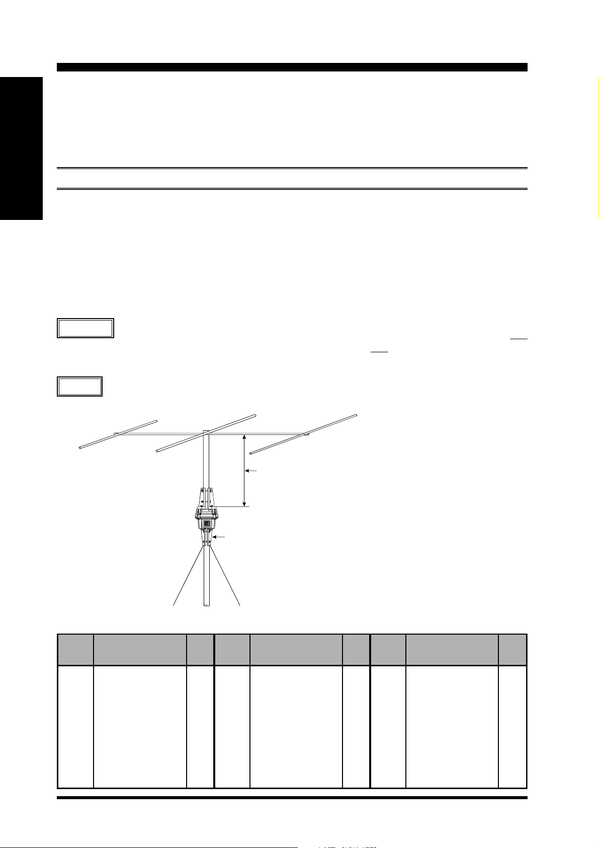
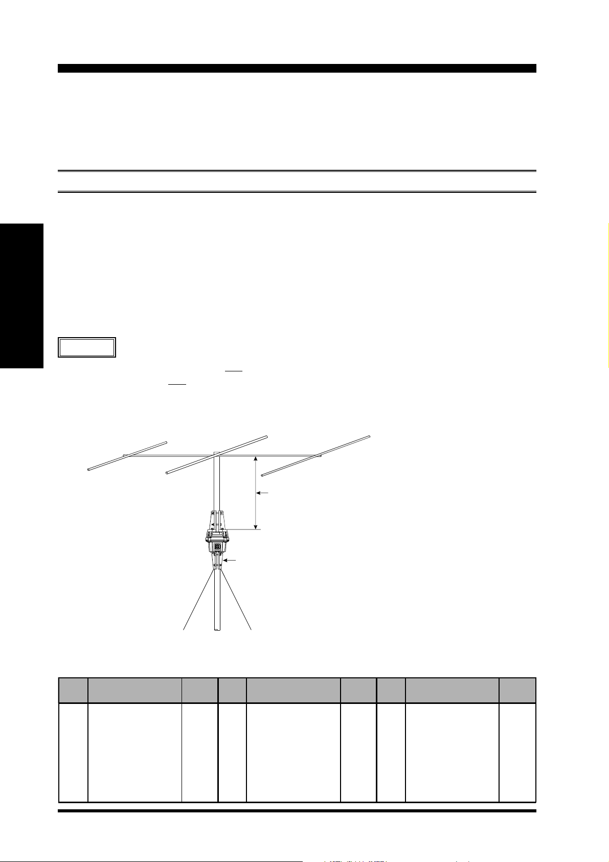
POLE-MOUNTED ANTENNAS
Mounting of the rotator on a pole or mast results in a significant de-rating of the size of the antenna which can be
mounted, due to the tremendous bending forces applied to the rotator’s clamps. For pole mounting, the product of
multiplying the [Antenna Wind Load Area (in m2)] by the [Height of the Antenna Mast (in m)] must be less than 0.45
(G-1000DXC) or 0.8 (G-2800DXC). See below Table and Figure.
[
Antenna Wind Load Area
] x [
Height of Antenna Mast] = 0.45 (G-1000DXC)
0.8 (G-2800DXC)
Refer to the antenna manufacturer’s specification sheet for determining the weight and the surface area of the proposed
antenna.
Example
For a 14 MHz 3-element Yagi of Surface area of 0.7 m2 (see Table 1), the above specifications for pole
mounting will be met if the antenna is mounted on a mast not longer than 0.4 m (0.7 m2 x 0.4 m = 0.28
= 0.28 [0.45 x 40% safety margin]: G-1000DXC), or 0.6 m (0.7 m2 x 0.6 m = 0.42 < 0.48 [0.8 x 40% safety margin]:
G-2800DXC).
We recommend that your antennas/mast should not exceed 60% of the maximum rating, to ensure a
Advice
safety margin.
Less than 0.4m (G-1000DXC) or 0.6m (G-2800DXC)
Band
(MHz)
7
7
7
7
14
14
14
21
21
21
21
21
Wind Loading Areas for Common Antennas (Typical)
Elements
2-element
1-element, w/loading coils
2-element, w/loading coils
3-element, w/loading coils
3-element
4-element
5-element
3-element
4-element
5-element
6-element
2-element, Swiss Quad
Area
(m
2.2
0.2
0.6
1.1
0.7
1.2
1.7
0.45
0.6
0.8
1.3
0.3
Optional Mast Clamp GC-038 (for G-1000DXC) or GC-048 (for G-2800DXC)
Example of a 14 MHz Band, 3-Element Yagi Antenna
2
)
Band
(MHz)
28
28
28
28
7/14
7/14
14/21
14/21
21/28
21/28
14/21/28
14/21/28
Elements
3-element
4-element
5-element
2-element, Swiss Quad
3-element, trapped
4-element, trapped
3-element, trapped
4-element, trapped
3-element, trapped
4-element, trapped
3-element, trapped
4-element, trapped
Area
(m
0.3
0.42
0.6
0.3
0.5
0.8
0.4
0.5
0.3
0.4
0.4
0.5
2
)
Band
(MHz)
50
50
50
50
14 4
14 4
14 4
14 4
43 0
43 0
43 0
43 0
Elements
4-element
5-element
6-element
2-element, Swiss Quad
10 - ele me nt
10-elem ent, stacked
10-element, x 4
10-element, x 4 x 2
12 - ele me nt
12-elem ent, stacked
12-element, x 4
12-element, x 4 x 2
G-1000DXC/-2800DXC User ManualPage 6
Area
(m
0.25
0.3
0.37
0.3
0.2
0.44
0.95
2.0
0.06
0.12
0.3
0.6
2
)
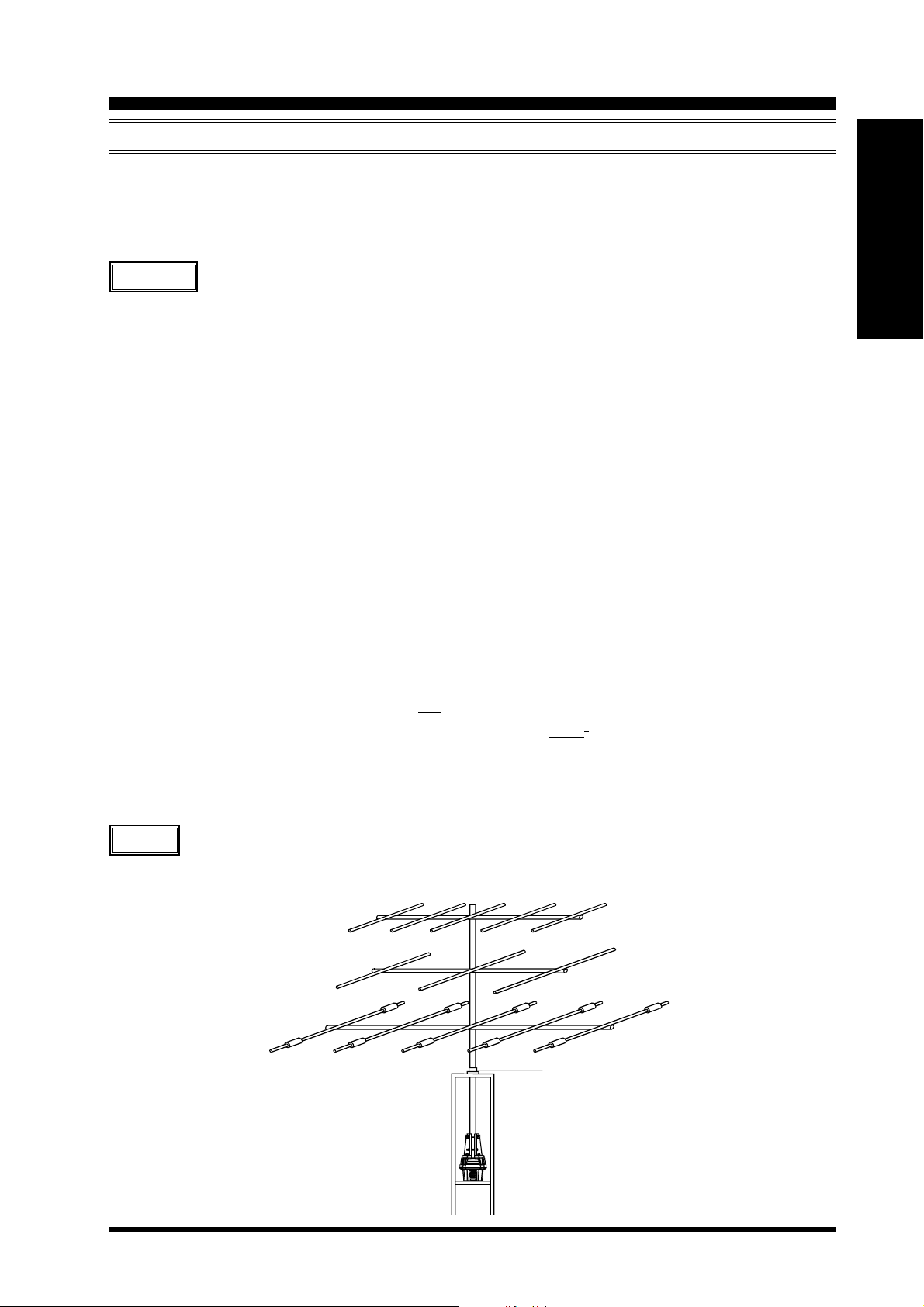
Antenna Considerations
TOWER-MOUNTED ANTENNAS
In the preferred tower-mounting configuration, the antenna Wind Loading Area must be less than 2.2 m2 (G-1000DXC)
or 3 m2 (G-2800DXC), and the “K” factor (see below) must not exceed 230 (G-1000DXC) or 950 (G-2800DXC),
where K = [Antenna Turning Radius (m)
Refer to the antenna manufacturer’s specification sheet for determining the turning radius and weight of the antenna.
] x [
Antenna + Mast Weight (kg)].
Example
(1) 14/21/28 MHz 5-element Yagi of Turning Radius 5.6 m, Weight of 26 kg, and Surface area 0.7 m
(2) 18 MHz 3-element Yagi of Turning Radius 5.0 m, Weight of 14 kg, and Surface area 0.7 m
(3) 50 MHz 5-element Yagi of Turning Radius 2.6 m, Weight of 4.5 kg, and Surface area 0.3 m
Note: In such “Christmas Tree” installations, compute the mast weight separately for each antenna, using the relative
heights of the antennas to apportion the mast weight.
The antenna system K factor, then, is the sum of the three antenna K factors:
K1 = K factor of 14/21/28 MHz 5-element Yagi.
K1 = Turning Radius (5.6 m) x Weight (26 kg + 2 kg) = 156.8
K2 = K factor of 18 MHz 3-element Yagi.
K2 = Turning Radius (5.0 m) x Weight (14 kg + 2 kg) = 80
K3 = K factor of 50 MHz 5-element Yagi.
K3 = Turning Radius (2.6 m) x Weight (5 kg + 2 kg) = 18.2
TOTAL
K
The antenna system Wind Loading Area is: 0.7 m2 + 0.7 m2 + 0.3 m2 = 1.7 m
In this example, mount the following antennas stacked on a 6 kg mast.
Antenna Weight Mast Weight (6 kg/3)
Antenna Weight Mast Weight (6 kg/3)
Antenna Weight Mast Weight (6 kg/3)
= K1 + K2 + K3 = 156.8 + 80 + 18.2 = 255
2
2
2
2
English
The Wind Loading Area (1.7 m2) is within the specifications for both the G-1000DXC and G-2800DXC, but the net K
factor (255) can only be met by the G-2800DXC. Therefore, the above antenna system should only be mounted using
a G-2800DXC.
Advice
We recommend that your antennas/mast should not exceed 60% of the maximum rating, to ensure a
safety margin.
Mast Bearing GS-065 (option)
Note: Installation of a Thrust Bearing such as
the GS-065 does not allow the elimination of the
mast weight from the K-factor calculations above.
G-1000DXC/-2800DXC User Manual Page 7

Mounting the Rotator and Antenna
INDOOR PERFORMANCE CHECK AND ALIGNMENT
1. Temporarily connect the rotator unit and the controller using the supplied connection cable.
2. Turn the SPEED control fully counter-clockwise,
and set the SELECT SWITCH on the rear panel to
the right (
3. Check to be sure that the POWER switch on the
English
controller is set to “OFF,” then plug the controller’s
ADJ. MODE) position.
AC cable into your station’s AC outlet.
4. Set the controller’s POWER switch to “ON.” Verify
that the controller’s pilot lights have become illuminated.
5. Press the LEFT (rotation) side of the seesaw switch,
and continue to hold it until the rotator reaches the
counter-clockwise position where it automatically
stops (“Left” represents counter-clockwise rotation
when the rotator is viewed from the top).
6. When the rotator has reached the left “stop” position, release the LEFT switch, and check to see if
the controller’s indicator needle is pointing to 0° (N:
North).
If the indicator needle is out of alignment, grasp the
edge of the bezel around the bearing window, turn it
10 ° counter-clockwise, and pull it off. Then, grasp
the needle at its center and pull it straight off, replace the needle to 0° (straight up), and replace the
bezel.
7. Just above the round connector jack on the rotator
unit, you will observe two raised calibration marks
(one each on the “rotating” bell and “fixed” base of
the rotator). These two marks should be directly
aligned with each other. If not, place a small piece
of masking tape on the rotating bell and the fixed
base of the rotator unit, and make a calibration mark
will be used to verify the amount of rotation in the
next step.
8. Press the RIGHT (rotation) side of the seesaw switch,
and continue rotating to the right until the calibration marks (from step 7) are again precisely aligned.
Now check the indicator needle, which should also
have rotated fully 360° so as to be pointing exactly
to 0°.
If the indicator needle is not pointing exactly to 0°,
go to the rear panel of the controller, and use a small
screwdriver to adjust the FULL SCALE ADJ potentiometer (see below) so that the indicator needle
points exactly to 0°.
9. Press the RIGHT switch again, and continue rotation to the right. You should observe the OVER-
LAP LED becoming illuminated as rotation passes
the 360° point.
If the OVERLAP LED does not light up at the 360°
position, the OVERLAP LED ADJ potentiometer
(on the rear panel of the controller) may be used to
align the illumination threshold to the 360° point.
10. Check to verify that rotation automatically stops at
approximately 90° (East; representing a total rotation range of 450° from the original starting point).
11. Press the LEFT and RIGHT (rotation) switches a
few more times, verifying that rotation appears to
be normal. If so, press the LEFT or RIGHT (rotation) switch to set the rotator to 90° (East).
12. Set the PRESET control to 0° (fully counter-clockwise), and press the START switch. The rotator
should rotate counter-clockwise, and stop exactly at
0°.
If not, go to the rear panel of the controller, and use
a small screwdriver to adjust the PRESET ADJ A
potentiometer so that the rotator stops at exactly 0°.
13. Set the PRESET control to 90° (fully clockwise),
and press the PRESET switch. The rotator should
rotate clockwise, and stop at exactly 450° (90°; East).
If not, go to the rear panel of the controller, use a
small screwdriver to adjust the PRESET ADJ B
potentiometer so that the rotator stops at exactly
450°.
14. Repeat steps 12 and 13 several times until the indicator responds reliably to presetting small angles
when the rotator is near both ends of its range.
15. Set the SELECT SWITCH on the rear panel to the
left (
OPERATION MODE) position, and turn the
POWER switch “OFF.”
16. This completes the ground-based testing of the rotator and controller.
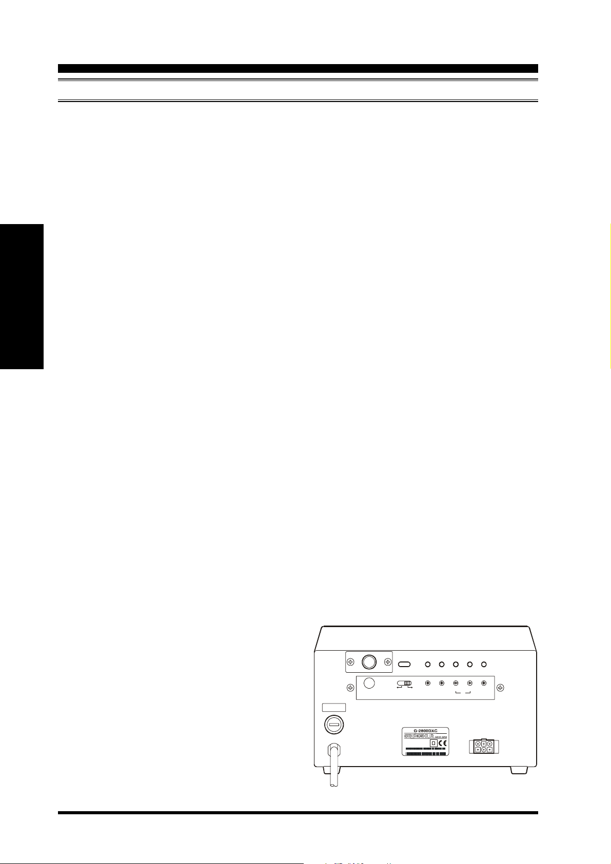
OPERATION
ADJ. MODE FULL
T 1A L
CONTROL
MODE
EXT
SELECT
SWITCH
INPUT AC22 0 - 240 V~
0.7A 50 - 60Hz
SCALE
ADJ
SER. NO. 000000000
OVERLAP
LED ADJ
AB
PRESET
ADJ
OUT VOL
ADJ
Controller Rear Panel
G-1000DXC/-2800DXC User ManualPage 8

Mounting the Rotator and Antenna
INDOOR PERFORMANCE CHECK AND ALIGNMENT
Installing the Dial Heading Sheet
A clear plastic round dial heading sheet is provided with the kit, which can be installed with north at any position you
desire. This is particularly useful when you need to have south at the top of the dial (or east or west) instead of north. To
install the heading scale:
Turn on the POWER switch and press the seesaw switch
to set the indicator needle to 0° (straight up), then turn off
the POWER switch.
Grasp the edge of the bezel around the bearing window,
turn it 10° counter-clockwise, and pull it off.
Note the position of the needle, then grasp it at its center,
and pull it straight off.
Determine which compass direction you desire to be upmost,
and install the compass heading label sheet against the azimuth scale, so that the small teeth in the edges of the sheet
lock around the edge.
Replace the needle and bezel in the same direction as they
were before (see diagram at the right).
Azimuth Indicator Needle
Bezel
Dial Heading Sheet
English
PRESET Knob Calibration
Perform this procedure only if it is not possible to align the PRESET knob tracking using the PRESET ADJ A and
PRESET ADJ B potentiometers on the rear panel, as described in steps 12 ~ 14 on the previous page.
Pull off the PRESET control knob.
Set the potentiometer shaft to the fully counter-clockwise
Knob
30°
Stopper
position, then turn it 30° clockwise.
Using care not to disturb the PRESET potentiometer, push
the knob back on the shaft so that the knob stopper is aligned
with the counter-clockwise edge of the slot in the panel behind the knob, as shown in the drawing to the right.
Repeat steps 12 and 13 on the previous page for the PRE-
SET Dial Tracking Alignment.
Do not forget to set the SELECT SWITCH on the rear
panel to the left (OPERATION MODE) position after align-
ment.
Stopper Limit
Potentiometer Shaft
G-1000DXC/-2800DXC User Manual Page 9

Mounting the Rotator and Antenna
INSTALLATION OF THE G-1000DXC ROT ATOR AND ANTENNA
ON TOWER
Important!! Before mounting the mast to the rotator, a
single hole must be drilled through the bottom of the
mast to accommodate an anti-twist support bolt used in
the base support clamp halves.
English
1. Drill a 9 mm diameter hole through both walls of
the mast, centered 50 mm from the mast bottom (see
Figure 1). Ensure the drill is maintained perpendicular and centered when making the holes, to ensure
proper alignment of the holes in the mast with those
in the base support clamp.
2. Attach the rotator to the tower’s rotator mounting
plate, using the supplied M8 x 16 bolts and spring
washers. It is recommended that the tips of the bolts
be lightly dipped in lubricating grease, to ease disassembly in the future (see Figure 2).
3. If a thrust bearing (such as the optional Yaesu model
GS-065) is to be utilized, mount it on the top of the
tower (see Figure 3) using the supplied hardware.
4. Partly tighten the mast clamp to the rotator housing using the supplied M8 x 25 bolts , spring
washers and flat washers (see Figure 5).
5. Using a “gin pole” or other raising fixture, insert the
antenna mast through the bearing from above, and
set the mast in the rotator’s mast clamps, then partly
tighten the mast clamps using the supplied M8 x 70
bolts and spring washer.
Advice
should be inserted from this side, so the ridges hold
the bolt head from turning.
6. Pass the supplied M8 x 95 screw through the
mast clamps and through the mast, then partly tighten
it using the supplied square nut .
7. Partly tighten the thrust bearing’s mast bolts, so as to
center the mast in the thrust bearing. When you are
satisfied that the mast is centered, tighten the thrust
bearing’s mast bolts to secure the mast in place.
8. Now tighten all the nuts of the mast clamp except
for the square nut holding the M8 x 95 bolt through
the mast clamps and mast. Leave the square nut only
lightly secured at this time.
Caution
ened until the spring washer becomes flat, then tightened further by ½ to one turn maximum.
One side of the clamp has ridges on
either side of the bolt holes; the bolts
Do not over-tighten the nuts on the
mast clamps. They should be tight-
9. Install the rotator control cable’s round plug into the
jack on the side of the rotator’s base, and tighten the
connector ring to secure the connector. Slide the rubber boot over the connector; while putting a slight
amount of inward pressure on the rubber boot, use
electrical tape to secure the back end of the rubber
boot to the cable. This slight inward pressure on the
rubber boot will enhance the weatherproofing of the
installation. Secure the control cable to the tower in
several places, using electrical tape and/or UV-resistant cable ties.
10. Get a ground crew member to set the controller to
0° (North), which corresponds to 180° of rotation
clockwise from the left “stop” point. During rotation, watch the M8 x 95 bolt to be sure it does not
bind between the mast and the mast clamps. If binding is observed, stop rotation and make slight adjustments to the thrust bearing and/or mast clamps,
so as to eliminate the binding. If the M8 x 95 bolt is
not binding, you can go ahead and tighten the square
nut securely.
11. Provide sufficient slack in the coaxial cable such
that the antenna can rotate over its full 450° range
without putting any tension on the coax (see Figure
8). Secure the coax to the tower, using electrical tape
and/or UV-resistant cable ties.
12. Installation is now complete. If you have scratched
through the melamine coating of the rotator during
installation, you may wish to apply several coats of
clear acrylic spray to help protect the bare metal from
corrosion. After installation is complete, test the system by operating the rotator through the entire range
of its rotation. It is helpful to do so with the help of
an observer, so that rotation can be stopped if some
obstruction, binding, or tension on the coaxial cable’s
turning loop should be encountered during the performance test.
Installation Note
If using a roof tower with a long mast between
the top of the tower and the antenna, the use of a
“Guy Bearing” is highly recommended. The
Yaesu GS-050 and GS-065 include guying
“ears” which allow attachment of guy cables. As
installing a guying system may cause the centerlines of the guy bearing and the rotator to become
mis-aligned, be certain to check the roof tower
attachment and guy cable alignment to ensure that
the mast is straight.
G-1000DXC/-2800DXC User ManualPage 10

Mounting the Rotator and Antenna
INSTALLATION OF THE G-1000DXC ROTATOR AND ANTENNA
ON TOWER
Figure 1 Figure 3Figure 2
English
Mast
Mast Gauge
Figure 5Figure 4 Figure 6
Figure 7 Figure 8
G-1000DXC/-2800DXC User Manual Page 11
Mounting the Rotator and Antenna
INSTALLATION OF THE G-2800DXC ROT ATOR AND ANTENNA
ON TOWER
Important!! Before mounting the mast to the rotator, a
single hole must be drilled through the bottom of the
mast to accommodate an anti-twist support bolt used in
the base support clamp halves.
English
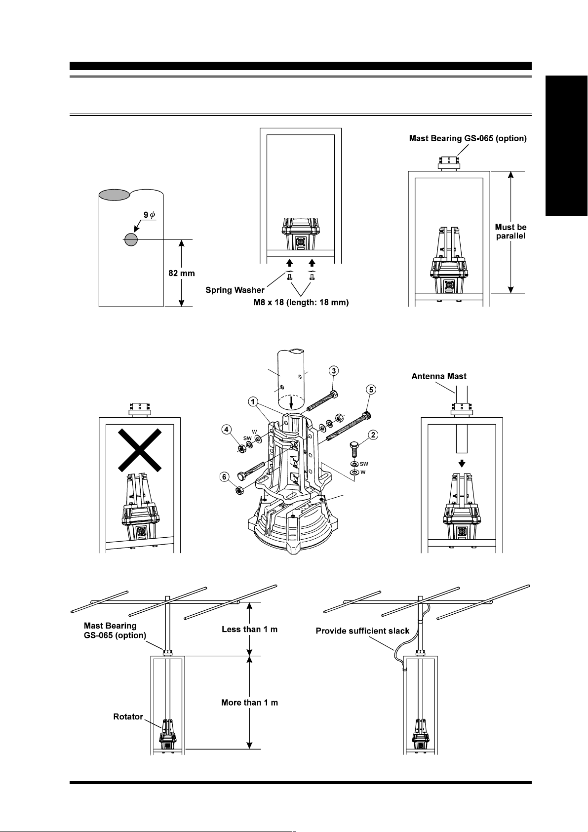
1. Drill a 9 mm diameter hole through both walls of
the mast, centered 82 mm from the mast bottom (see
Figure 9). Ensure the drill is maintained perpendicular and centered when making the holes, to ensure
proper alignment of the holes in the mast with those
in the base support clamp.
2. Attach the rotator to the tower’s rotator mounting
plate, using the supplied M8 x 18 bolts and spring
washers. It is recommended that the tips of the bolts
be lightly dipped in lubricating grease, to ease disassembly in the future (see Figure 10).
3. If a thrust bearing (such as the optional Yaesu model
GS-065) is to be utilized, mount it on the top of the
tower (see Figure 11) using the supplied hardware.
4. Partly tighten the mast clamp to the rotator housing using the supplied M8 x 30 bolts , spring
washers and flat washers (see Figure 13).
5. Using a “gin pole” or other raising fixture, insert the
antenna mast through the bearing from above, and
set the mast in the rotator’s mast clamps, then partly
tighten the mast clamps using the supplied M8 x 70
bolts , spring washers and flat washers.
Advice
should be inserted from this side, so the ridges hold
the bolt head from turning.
6. Pass the supplied M8 x 95 screw through the
mast clamps and through the mast, then partly tighten
it using the supplied nut .
7. Partly tighten the thrust bearing’s mast bolts, so as to
center the mast in the thrust bearing. When you are
satisfied that the mast is centered, tighten the thrust
bearing’s mast bolts to secure the mast in place.
8. Now tighten all the nuts of the mast clamp except
for the nut holding the M8 x 95 bolt through the
mast clamps and mast. Leave this nut only lighly
secured at this time.
Caution
ened until the spring washer becomes flat, then tightened further by ½ to one turn maximum.
One side of the clamp has ridges on
either side of the bolt holes; the bolts
Do not over-tighten the nuts on the
mast clamps. They should be tight-
9. Install the rotator control cable’s round plug into the
jack on the side of the rotator’s base, and tighten the
connector ring to secure the connector. Slide the rubber boot over the connector; while putting a slight
amount of inward pressure on the rubber boot, use
electrical tape to secure the back end of the rubber
boot to the cable. This slight inward pressure on the
rubber boot will enhance the weatherproofing of the
installation. Secure the control cable to the tower in
several places, using electrical tape and/or UV-resistant cable ties.
10. Get a ground crew member to set the controller to
0° (North), which corresponds to 180° of rotation
clockwise from the left “stop” point. During rotation, watch the M8 x 95 bolt to be sure it does not
bind between the mast and the mast clamps. If binding is observed, stop rotation and make slight adjustments to the thrust bearing and/or mast clamps,
so as to eliminate the binding. If the M8 x 95 bolt is
not binding, you can go ahead and tighten the nut
securely.
11. Provide sufficient slack in the coaxial cable such
that the antenna can rotate over its full 450° range
without putting any tension on the coax (see Figure
16). Secure the coax to the tower, using electrical
tape and/or UV-resistant cable ties.
12. Installation is now complete. If you have scratched
through the melamine coating of the rotator during
installation, you may wish to apply several coats of
clear acrylic spray to help protect the bare metal from
corrosion. After installation is complete, test the system by operating the rotator through the entire range
of its rotation. It is helpful to do so with the help of
an observer, so that rotation can be stopped if some
obstruction, binding, or tension on the coaxial cable’s
turning loop should be encountered during the performance test.
Installation Note
If using a roof tower with a long mast between
the top of the tower and the antenna, the use of a
“Guy Bearing” is highly recommended. The
Yaesu GS-050 and GS-065 include guying
“ears” which allow attachment of guy cables. As
installing a guying system may cause the centerlines of the guy bearing and the rotator to become
mis-aligned, be certain to check the roof tower
attachment and guy cable alignment to ensure that
the mast is straight.
G-1000DXC/-2800DXC User ManualPage 12
Mounting the Rotator and Antenna
INSTALLATION OF THE G-2800DXC ROTATOR AND ANTENNA
ON TOWER
English
Figure 9
Figure 11Figure 10
Mast
Mast Gauge
Figure 13Figure 12 Figure 14
Figure 15 Figure 16
G-1000DXC/-2800DXC User Manual Page 13

Important !
The installation of a rotatable antenna on a tower system
is a dangerous and potentially life-threatening task, if
due care is not taken.
A tower must never be installed in a position where it
could fall across power distribution cables in the event
of a catastrophic tower failure during a windstorm or
earthquake.
English
The control cable attached to this rotator could, in the
event of a nearby or direct lightning strike, carry lethal
voltages down the cable and into your home. Yaesu
strongly recommends the installation of suitable lightning arrestors on all control cables and coaxial lead-in
cables from your antenna installation. See your dealer
for details of available lightning-protection devices.
If an electrical storm should be reported in your area,
G-1000DXC/-2800DXC User ManualPage 14

Specifications
quickly unplug the control cable from the rear of the rotator’s controller box, and disconnect the AC cable from the wall
outlet. Disconnect the coaxial cable(s) from the antenna(s) as well. Do this only if the lightning is not in your immediate
area, as you could be killed instantly if lightning should strike while you are holding a cable.
If you have any doubts about your ability to install this rotator safely, enlist the services of a professional antenna
installation company.
G-1000DXC G-2800DXC
Power Supply Voltage: 220 – 240 VAC, 50 – 60 Hz 220 – 240 VAC, 50 – 60 Hz
Power Supply Current Consumption: 0.5 A 0.7 A
Rotor Voltage: 11 – 24 VDC 11 – 24 VDC
360° Rotation Time (Non Loaded): 100 ± 10 sec to 40 ± 5 sec (Variable) 120 ± 10 sec to 50 ± 5 sec (Variable)
Rotation Range: 450° ± 3° 450° ± 3°
Rotation Torque (@230 VAC): 600 to 1,100 kgf-cm 800 to 2,500 kgf-cm
Braking Torque: 6,000 kgf-cm 25,000 kgf-cm
Maximum Vertical Load: 200 kg or less (continuous) 300 kg or less (continuous)
800 kg (momentary) 1,200 kg (momentary)
Mast Outside Diameter: φ38 to φ63 φ48 to φ63
Braking Type: Mechanical and Electrical stoppers Mechanical and Electrical stoppers
Antenna K Coefficient: 230 or less 950 or less
Wind Loading Area: 0.75 m2 x 0.6 m or less (Pole Type) 1 m2 x 0.8 m or less (Pole Type)
2.2 m2 or less (Tower Type) 3 m2 or less (Tower Type)
Maximum Continuous Duty: 3 minutes 3 minutes
Operating Temperature Range: 0 °C to +40 °C (Controller) 0 °C to +40 °C (Controller)
–20 °C to +40 °C (Rotator) –20 °C to +40 °C (Rotator)
Rotator Dimensions: φ186 x 300 mm φ200 x 345 mm
Rotator Weight: Αpprox. 3.6 kg Αpprox. 6.5 kg
Controller Dimensions: 200 (W) x 130 (H) x 193 (D) mm 200 (W) x 130 (H) x 193 (D) mm
Controller Weight: Approx. 2.8 kg Approx. 3.8 kg
English
This equipment complies with the following standard:
EMC Directive 89/336/EEC: EN50081-1 & EN50082-1
LVD 73/23 EEC: EN60065
Specifications are subject to change without notice.
Rotator Attachment Dimensions
G-1000DXC/-2800DXC User Manual Page 15

Accessories & Options
UNPACKING & INSPECTION
When unpacking the rotator make sure you find the following items:
G-1000DXC QUANTITY
Controller Unit 1
Rotor Unit 1
Mast Clamp 1 pair
Connection Cable (25m, 6 core cable) 1
English
M8 x 95 mm Socket Head Cap Screw 1
M8 x 16 mm Hex Bolts 4
M8 x 25 mm Hex Bolts 4
M8 x 70 mm Hex Bolts 4
Split Washers 14
Flat Washers 4
M8 Nuts 4
Square Nut 1
Spare Fuse 1 (1A)
Plastic Dial Heading Sheet 1
If any of these items are missing or damaged, save the packing material and notify the shipping company (or the shop where
your bought it).
G-2800DXC QUANTITY
Controller Unit 1
Rotor Unit 1
Mast Clamp 1 pair
Connection Cable (40m, 6 core cable) 1
M8 x 95 mm Socket Head Cap Screw 1
M8 x 18 mm Hex Bolts 4
M8 x 30 mm Hex Bolts 4
M8 x 70 mm Hex Bolts 6
Split Washers 14
Flat Washers 10
M8 Nuts 7
Spare Fuse 1 (1A)
Plastic Dial Heading Sheet 1
OPTIONAL ACCESSORIES
GC-038 Mast Clamp (for the G-1000DXC)
GC-048 Mast Clamp (for the G-2800DXC)
GS-050 Universal Thrust Bearing (for 50 mm mast)
GS-065 Universal Thrust Bearing (for 65 mm nast)
GS-232A Computer Control Unit (RS-232C Serial)
G-40MWP Control Cable (40 m: for the G-1000DXC)
GA-2500 Absorber Joint (for the G-1000DXC)
GA-3000 Absorber Joint (for the G-2800DXC)
G-1000DXC/-2800DXC User ManualPage 16
Rotador y Controlador de Antena Para
Servicio Pesado,
Modelos G-1000DXC y G-2800DXC
Las unidades de control G-1000DXC y G-2800DXC
de Yaesu están proyectadas para orientar a distancia
sistemas de antenas amateur y profesionales de gran
tamaño montados sobre torres desde el lugar donde se
encuentra emplazada la estación. El diseño del rotador
semejante al de una concha de almeja emplea 100
rodamientos circulares dobles de 7/16 pulgadas para
distribuir la carga por todo el diámetro de la caja. Este
diseño minimiza el esfuerzo y el desgaste de material, y
prácticamente elimina los eventuales efectos destructivos
del agua: no existe un agujero para el eje en la parte
superior de la cubierta del referido aparato.
En lugar del sistema de accionamiento por motor de CA
utilizado en los modelos de rotador más antiguos, el G-
1000DXC y el G-2800DXC vienen equipados con un
motor de CC de voltaje variable, eliminando de esta
forma la necesidad de un condensador de arranque grande
y sus posibles fallas al ser expuesto a los cambios de
temperatura atmosférica. La unidad de rotador que viene
lubricada de fábrica se aloja en una caja de aluminio
fundido a presión cubierta de resina de melamina, a fin
de garantizar el servicio ininterrumpido de la misma
cualquiera sean las condiciones climáticas
preponderantes en cada lugar en particular. Un calibrador
para mástil en la cubierta del rotador ayuda a definir la
alineación mecánica exacta durante la instalación.
de “partida” y “parada automática lenta” evitan que se
produzcan sacudidas bruscas en la torre al igual que en
la estructura de antena múltiple. Al activar el rotador,
dicha estructura comienza a girar a velocidad reducida.
A medida que la antena se acerca al punto deseado, la
velocidad de rotación disminuye automáticamente antes
de detener la estructura con suavidad al final de su
recorrido. El operador puede seleccionar el acimut límite
(la posición angular más allá de la cual el rotador no se
puede girar) que mejor le acomode dependiendo de su
ubicación y finalidad, lo cual le permite -si así lo desearealizar una rotación completa en dirección norte, sur o
en ambos sentidos a la vez. En todo caso, una rotación
superpuesta de 90° le permite realizar un giro a través
del acimut límite seleccionado (cuya rotación total es de
450°).
El rotador está proyectado para ser instalado en el interior de una torre de soporte (la cual no viene incluida),
por lo menos a 1 metro del tope, con un cojinete de
empuje alternativo (modelo GS-680U de Yaesu) en la
parte de arriba. Este conjunto incluye una abrazadera
para mástil y las piezas metálicas necesarias, además de
conectores machos para el rotador y el controlador
respectivamente, con el objeto de hacer más fácil la
instalación y manutención del aparato. El Cable de Control G-40MWP de 40 metros de longitud es optativo.
EspañolEspañol
El atractivo controlador de mesa armoniza perfectamente
con el diseño de los transceptores más modernos, el cual
incluye la lectura radial de 360° del acimut real de la
antena. El usuario puede escoger velocidades de rotación
que oscilan entre 40 y 100 segundos por giro (360°) (G-
1000DXC, G-2800DXC: de 50 a 120 segundos por giro
(360°)), además de fijar una trayectoria de interés para
el rotador, en cuya dirección éste ha de volverse
posteriormente en forma automática.
En el modelo G-2800DX, cuando se selecciona la
velocidad de rotación rápida, las funciones especiales
La Unidad de Control por Computadora GS-232A se
vende aparte para ser instalada en el controlador, la cual
le permite orientar la antena haciendo uso de una
computadora personal unida a una interconexión serial
RS-232.
Antes de montar el rotador, haga el favor de leer este
manual con atención, a fin de que pueda familiarizarse
con los procedimientos requeridos y también para
cerciorarse de que cuenta con todos los materiales que
necesita para su instalación.
Manual de Instrucciones del G-1000DXC/-2800DXC Page 1

6
6
6
5
5
5
8
8
7
7
Utilización Correcta y Segura del Equipo
234567890123456789012345678901212345
234567890123456789012345678901212345
234567890123456789012345678901212345
Advertencia
Precaución
2345678901234567
2345678901234567
Indica que siempre se deben seguir las
instrucciones relacionadas a fin de
garantizar el debido funcionamiento del
equipo.
Español
Haga el favor de leer de principio a fin el
presente manual del usuario, de modo
que pueda familiarizarse con el debido
procedimiento de instalación antes de
comenzar a montar el equipo.
La instalación de este producto requiere que se
realicen trabajos en altura. El usuario, al ejecutar
trabajos con los que no está familiarizado, puede
correr el riesgo de sufrir accidentes fatales a
causa de caídas durante la instalación.
Del mismo modo, el hecho de no instalar
debidamente el producto puede hacer que la
antena y el equipo relacionado terminen por
derrumbarse, ocasionando por ende accidentes
fatales, como también la destrucción de
viviendas u otros daños materiales.
Por consiguiente, antes de empezar a trabajar
lea todas las pautas relativas a la seguridad.
Verifique que la dimensión de la antena
asociada a este producto coincida con
las especificaciones incluidas en el
manual.
El hecho de instalar una antena más grande que
la estipulada en las especificaciones puede hacer
que dicha antena y el equipo relacionado
terminen por derrumbarse, ocasionando por
ende accidentes fatales, como también la
destrucción de viviendas u otros daños
materiales.
23456789012345678901234567890121234
23456789012345678901234567890121234
Significado de los Símbolos
23456789012345678901234567890121234
denota que al no seguir las instrucciones relacionadas, podría
causar la muerte o heridas graves al operador.
denota que al no seguir las instrucciones relacionadas, podría
causar heridas o lesiones operador.
Significado de los Símbolos en los Diagramas
Denota procedimientos poco seguros
que jamás deben ser ejecutados.
Advertencia
Cuando trabaje en altura, asegúrese de
que no hayan personas transitando a
nivel del suelo.
Si se caen herramientas, pernos u otras piezas
podrían ocasionar la muerte o lesiones graves a
las personas.
Use siempre un arnés de seguridad
cuando trabaje en altura.
Si no utiliza un arnés de seguridad, el usuario
podría lesionarse gravemente o incluso perder
la vida al hacer la instalación.
Cerciórese de que los pernos y demás
fiadores utilizados en la instalación
queden debidamente ajustados.
El hecho de no apretar bien los pernos y demás
fiadores puede hacer que la antena y el equipo
relacionado terminen por derrumbarse,
ocasionando por ende accidentes fatales, como
también la destrucción de viviendas u otros
daños materiales.
Jamás desarme ni modifique esta
unidad.
234567890123456
234567890123456
Manual de Instrucciones del G-1000DXC/-2800DXCPage 2
Utilización Correcta y Segura del Equipo
Precaución
Cuando instale este producto, tenga
cuidado de no apretarse los dedos entre las piezas ni de cortárselos con los
bordes de éstas.
Si la condición del equipo no es normal,
como sería la emisión de humo o un olor
poco usual, el hecho de continuar
usándolo en ese estado podría provocar
un incendio o desperfectos en el interior de la unidad.
En tales circunstancias, apague inmediatamente
el equipo y retire el conector del enchufe de
alimentación.
Después de comprobar que el equipo ha dejado
de emitir humo o el olor poco usual, devuélvale
el producto al vendedor o diríjase a la oficina
de Yaesu Musen más cercana o en su defecto, al
centro de servicio técnico para su reparación.
En caso de que cuerpos extraños
cayeran dentro del controlador, apague
el equipo de inmediato y retire el
conector del enchufe de alimentación.
Si continúa usando el producto en esas
condiciones podría provocar un incendio o
desperfectos dentro de la unidad.
Jamás use el producto con una tensión
de alimentación distinta a la
especificada, puesto que de lo contrario
corre el riesgo de provocar un incendio
o electrochoques en el interior de la
unidad.
Si no se ha de utilizar el producto por
un período de tiempo prolongado, saque
el cable de alimentación del enchufe por
razones de seguridad.
No haga funcionar el equipo por más de
3 minutos seguidos.
El equipo puede funcionar por periodos de hasta
5 minutos a la vez, pero es necesario hacer una
pausa y dejar que el motor descanse por lo
menos durante los 15 minutos siguientes.
En el interior del rotador ni el controlador
existen piezas que puedan ser reparadas
por el usuario; por consiguiente nunca
abra estas unidades.
No coloque el controlador en un lugar
inestable, como sería el caso de una
superficie frágil o inclinada, debido a que
el aparato podría volcarse o caerse y
lesionar a alguna persona
accidentalmente.
No coloque objetos pesados sobre el
cordón de alimentación, tampoco doble
ni estire demasiado el cable.
Si se daña el cable de alimentación puede provocar
un incendio o desperfectos dentro de la unidad.
No coloque el controlador a la luz directa
del sol ni cerca de calefactores, puesto que
se podría deformar o descolorar la caja.
No coloque el controlador en ambientes
húmedos ni polvorientos, ya que esto
puede ocasionar incendios o
desperfectos dentro de la unidad.
No coloque el controlador en lugares
encerrados o mal ventilados como una
repisa por ejemplo, ya que lo anterior
podría originar incendios o fallas dentro
de la unidad.
No coloque el controlador sobre una
alfombra o ropa de cama, debido a que
el calor podría acumularse internamente
originando un incendio.
No coloque objetos pesados sobre el
controlador, puesto que el aparato
podría caerse o voltearse y lesionar a
alguna persona accidentalmente.
No coloque objetos de metal pequeños
como clips para papel sobre el
controlador, ya que éstos pueden caer
dentro de la unidad y provocar incendios
o averías en el interior del aparato.
No limpie el controlador con solventes
tales como diluyentes o bencina, puesto
esas sustancias podrían deformar o
descolorar la caja.
Para limpiar el controlador, frótelo suavemente
con un paño húmedo y detergente neutro, y
remueva a continuación el producto utilizando
un paño seco.
Español
Nunca conecte la fuente de alimentación
hasta no haber completado primero la
instalación del rotador y el controlador.
Manual de Instrucciones del G-1000DXC/-2800DXC Page 3
Español
Panel Frontal del Controlador
Interruptor de Encendido “POWER”
Oprima este interruptor para encender el controlador
y hacer girar la antena. Apáguelo cuando no esté
utilizando el rotador.
Interruptor de Vaivén IZQUIERDO/DERECHO
Oprima el costado izquierdo (“LEFT”) de este
interruptor para hacer girar la antena en dirección
contraria a la marcha del reloj. Oprima el costado
derecho (“RIGHT”) cuando quiera orientar la antena
en sentido horario.
Control de AJUSTE PRELIMINAR e
Interruptor de ARRANQUE
Coloque el control de AJUSTE PRELIMINAR en la
trayectoria de la antena deseada de acuerdo con la
escala angular interior (0 ~ 90) situada alrededor de
dicho control y posteriormente oprima el interruptor
de ARRANQUE con el objeto de activar la rotación
automática en la dirección determinada. El usuario
puede oprimir el Interruptor de Vaivén IZQUIERDO/
DERECHO para abortar la función de ajuste previo.
Nota: Si cambia la posición de partida del rotador a
180° (S: Sur), entonces coloque el control de AJUSTE
PRELIMINAR en la trayectoria de la antena deseada
de acuerdo con la escala angular exterior (180 ~ 270)
situada alrededor de dicho control.
Control de VELOCIDAD
Ajuste el referido control para definir la velocidad
de rotación deseada, entre 30 y 100 segundos
aproximadamente por cada giro de 360°.
Indicador de SUPERPOSICIÓN
Este indicador LED de color rojo se ilumina cuando
se hace girar la antena más allá de los 360°
aproximadamente (hasta 450°), a contar de su última
posición de la izquierda. Revise este indicador antes de orientar la antena en sentido horario y si dicha
luz estuviera encendida, gírela a la izquierda hasta
dejarla ajustada en la posición deseada.
Manual de Instrucciones del G-1000DXC/-2800DXCPage 4
Panel Posterior del Controlador
OPERAT ION
T 1A L
EXT
CONTRO L
MODE
ADJ. MODE F ULL
SELECT
SWITCH
INPUT AC22 0 - 240V~
0.7A 50 - 60Hz
SER. NO. 000000000
SCALE
ADJ
OVERLAP
LED ADJ
AB
PRESET
ADJ
OUT V OL
ADJ
Español
Conector de CONTROL EXTERNO
Este minienchufe DIN de 6 alfileres de contacto se
utiliza para conectar la Unidad de Control Mediante
Computadora GS-232A.
CONMUTADOR DE SELECCIÓN
Coloque el conmutador en el •MODO DE AJUSTE
(ADJ)” cuando se disponga a calibrar los elementos
internos del controlador. No obstante, coloque el
referido conmutador en el “MODO DE OPERACIÓN•
durante la utilización normal del equipo.
Potenciómetro de AJUSTE DE PLENA ESCALA
Este control sirve para calibrar el ángulo (radio) de
rotación máximo correspondiente a la aguja acimutal,
a fin de que coincida con el ángulo máximo del rotador.
Potenciómetro de
AJUSTE DEL INDICADOR DE SUPERPOSICIÓN
Este control se utiliza para calibrar el Indicador de
SUPERPOSICIÓN de modo que coincida con el ángulo
acimutal de la aguja.
Potenciómetros de
AJUSTE PRELIMINAR (A & B)
Estos controles sirven para calibrar el ángulo
perteneciente al control de AJUSTE PRELIMINAR del
panel frontal, a fin de que coincida con el de la aguja
acimutal. El Potenciómetro A debe quedar ajustado
exclusivamente alrededor de la posición
correspondiente a 0° y el B, próximo a los 450°.
Potenciómetro de
AJUSTE DE VOLTAJE DE SALIDA
Este control define la gama de tensiones en el cuarto
alfiler de conexión del Miniconector DIN de 6
alfileres para CONTROL EXTERNO, a fin de calibrar el
convertidor de A a C en la Unidad de Control por
Computadora (optativa) modelo GS-232A.
Conector para el Cable de
Control del Rotador
En este enchufe de 6 alfileres de contacto se conecta
el cable de control proveniente del rotador que se
suministra con dicho aparato.
Portafusible
En este portafusible se debe instalar un fusible de 1A para tensión alterna entre 220 y 240 V. Si se funde
el fusible, cámbielo por otro de la misma capacidad.
Diríjase al distribuidor Yaesu para adquirir el
repuesto apropiado.
Cable de CA
Conecte este cable a la salida de alterna de 200
~240V de la pared.
Manual de Instrucciones del G-1000DXC/-2800DXC Page 5
Consideraciones Pertinentes a la Antena
Los tipos de antenas que se pueden conectar a este producto difieren considerablemente entre sí, lo cual depende del
método de instalación, de las características del terreno y de la velocidad máxima del viento de cada lugar en particular.
En las páginas a continuación se describen los tipos de antena de uso más corriente que es posible instalar en el
controlador G-1000DXC o G-2800DXC. En la siguiente exposición se presume que la velocidad del viento es de 30
metros por segundo, por lo que se recomienda incluir un margen de seguridad no inferior a un 30%, a fin de soportar
ráfagas de mayor intensidad o cualquier otro factor que potencialmente podría menoscabar su instalación.
ANTENAS MONT ADAS EN POSTE
Al instalar el rotador sobre un poste o mástil, se produce una corrección significativa del tamaño de la antena que puede
ser montada, debido a la tremenda fuerza de torsión que se le aplica a las abrazaderas del referido rotador. Para el
montaje en poste, el producto de multiplicar la [Superficie de Carga del Viento sobre la Antena (en m2)] por la [Altura
del Mástil (en m)] debe ser inferior a 0,45 (para el G-1000DXC) ó 0,8 (en el caso del G-2800DXC). Refiérase a la
tabla y a la ilustración que se presentan más adelante para ver los detalles relativos al tema.
[Superficie de Carga del Viento sobre la Antena] x [Altura del Mástil] = 0,45 (G-1000DXC)
0,8 (G-2800DXC)
Lea la hoja de especificaciones del fabricante para determinar el peso al igual que el área de superficie correspondiente
a la antena que pretende instalar.
Español
Ejemplo
de no más de 0,4 metro (0,7 m2 x 0,5 m = 0,28 = 0,28 [0,45 x 40% margen de seguridad]: G-1000DXC) ó 0,6 metro de
longitud (0,7 m2 x 0,6 m = 0,42 < 0,48 [0,8 x 40% margen de seguridad]: G-2800DXC).
En el caso de una Yagi de 3 elementos para 14 MHz con un área de Superficie de 0,7 m2 (vea la tabla 1),
las especificaciones anteriores para montaje en poste sí se cumplen si instala dicha antena en un mástil
Recomendación: Es aconsejable que ni las antenas ni el mástil excedan el 60 % de su capacidad máxima, a fin de
garantizar la existencia de un margen de seguridad en la instalación.
Menos de 0,4 m (G-1000DXC) ó 0.6m (G-2800DXC)
Abrazadera para Mástil GC-038 (para el G-1000DXC) ó
GC-048 (para el G-2800DXC) (optativa)
Modelo de una Antena Yagi de 3 Elementos para la Banda de 14 MHz
Superficies de Carga del Viento Para Antenas Comunes (Típicas)
Banda
(MHz)
7
2 el em entos
7
1 elemento con bobinas de carge
7
2 elementos con bobinas de carge
7
3 elementos con bobinas de carge
14
3 el em entos
14
4 el em entos
14
5 el em entos
21
3 el em entos
21
4 el em entos
21
5 el em entos
21
6 el em entos
21
2 elementos, Cuadrangular Suiza
Elemento s
Superficie
2
(m
)
2.2
0.2
0.6
1.1
0.7
1.2
1.7
0.45
0.6
0.8
1.3
0.3
Banda
(MHz)
28
3 el em entos
28
4 el em entos
28
5 el em entos
28
2 elementos, Cuadrangular Suiza
7/14
3 elementos, concatenados
7/14
4 elementos, concatenados
14/21
3 elementos, concatenados
14/21
4 elementos, concatenados
21/28
3 elementos, concatenados
21/28
4 elementos, concatenados
14/21/28
3 elementos, concatenados
14/21/28
4 elementos, concatenados
Elemento s
Superficie
(m2)
0.3
0.42
0.6
0.3
0.5
0.8
0.4
0.5
0.3
0.4
0.4
0.5
Banda
(MHz)
50
4 elem entos
50
5 elem entos
50
6 elem entos
50
2 elementos, Cuadrangular Suiza
14 4
10 elem entos
14 4
10 elementos, superpuestos
14 4
10 element, x 4
14 4
10 element, x 4 x 2
43 0
12 e le me nt
43 0
12 element, superpuestos
43 0
12 element, x 4
43 0
12 element, x 4 x 2
Elementos
Superficie
(m2)
0.25
0.3
0.37
0.3
0.2
0.44
0.95
2.0
0.06
0.12
0.3
0.6
Manual de Instrucciones del G-1000DXC/-2800DXCPage 6

Consideraciones Pertinentes a la Antena
ANTENAS MONTADAS EN TORRE
En la configuración de montaje en torre de mayor preferencia, la Superficie de Carga del Viento debe ser inferior a 2,2
m2 (G-1000DXC) ó 3 m2 (G-2800DXC), mientras que el factor “K” (ver a continuación) no debe superar los 230 (G1000DXC) ó 950 (G-2800DXC), en donde K = [Radio de Sintonización de la Antena (m)] x [Antena + Peso
del Mástil (kg)].
Lea la hoja de especificaciones del fabricante para determinar el radio de sintonización al igual que el peso de la antena
que va a instalar.
Ejemplo
(1)
(2)
(3)
Nota: En el caso de las instalaciones configuradas en “Espina de Pescado”, calcule el peso del mástil independientemente
para cada antena, utilizando las altitudes relativas de cada una para distribuir el peso del mástil.
El factor K del sistema de antenas, por consiguiente, equivale a la suma de los tres factores K:
K1 = Factor K de una Yagi de 5 elementos para 14/21/28 MHz.
K1 = Radio de Sintonía (5,6 m) x Peso (26 kg + 2 kg) = 156.8
K2 = Factor K de una Yagi de 3 elementos para 18 MHz.
K2 = Radio de Sintonía (5,0 m) x Peso (14 kg + 2 kg) = 80
K3 = Factor K de una Yagi de 5 elementos para 50 MHz.
K3 = Radio de Sintonía (2,6 m) x Peso (5 kg + 2 kg) = 18,2
TOTAL
K
La Superficie de Carga del Viento para el sistema de antena es de: 0,7 m2 + 0,7 m2 + 0,3 m2 = 1,7 m
En este ejemplo, superponga las siguientes antenas en un mástil de 6 kg.
Yagi de 5 elementos para 14/21/28 MHz con 5,6 m de Radio de Sintonía, Peso de 26 kg y una Superficie de área de 0,7 m
Yagi de 3 elementos para 18 MHz con 5,0 m de Radio de Sintonía, Peso de 14 kg y una Superficie de área de 0,7 m
Yagi de 5 elementos para 50 MHz con 2,6 m de Radio de Sintonía, Peso de 4,5 kg y una Superficie de área de 0,3 m
Peso de la Antena Peso del Mástil (6 kg/3)
Peso de la Antena Peso del Mástil (6 kg/3)
Peso de la Antena Peso del Mástil (6 kg/3)
= K1 + K2 + K3 = 156,8 + 80 + 18,2 = 255
2
2
.
2
.
2
.
Español
La Superficie de Carga del Viento (1,7 m2) cumple tanto con las especificaciones del rotador G-1000DXC como con
las del G-2800DXC; sin embargo, el factor K neto (255) sólo puede ser alcanzado por el segundo de ellos. Por
consiguiente, el sistema de antena que acabamos de describir se debe instalar únicamente utilizando el rotador G-
2800DXC.
Recomendación: Es aconsejable que ni las antenas ni el
mástil excedan el 60 % de su capacidad máxima, a fin
de garantizar la existencia de un margen de seguridad en
la instalación.
Cojinete de Empuje GS-065
(optativo)
Nota: La instalación de un Cojinete de Empuje como un GS-065
no permite eliminar el peso del mástil de los cálculos del factor K
que se realizaron anteriormente en la hoja.
Manual de Instrucciones del G-1000DXC/-2800DXC Page 7
Instalación del Rotador y la Antena
ALINEACIÓN Y PRUEBA DE LA UNIDAD EN EL INTERIOR
1. Conecte temporalmente la unidad del rotador y el
controlador con el cable de enlace que se suministra
con el equipo.
2. Gire el control de VELOCIDAD hasta la última posición
de la izquierda y coloque el I
NTERRUPTOR DE
SELECCIÓN ubicado en el panel posterior en la
regulación de la derecha (correspondiente al MODO
AJUSTE).
DE
3. Revise que el interruptor de ENCENDIDO del
controlador esté en la posición de desconexión
(“oFF”) e inserte posteriormente el cable en el
tomacorriente de alterna de su estación.
4. A continuación, coloque el interruptor de ENCENDIDO
del controlador en la posición de conexión (“ON”)
y cerciórese de que se hayan iluminado las luces
piloto del equipo.
5. Oprima el extremo (de rotación) IZQUIERDO del
Español
interruptor de vaivén y manténgalo en esa posición
hasta que el rotador alcance la regulación de la
izquierda en donde éste se detiene automáticamente
(el lado “izquierdo” representa un giro en sentido
contrahorario cuando se mira dicho aparato desde
arriba).
6. Una vez que el rotador haya alcanzado la posición
de “Parada” en ese extremo, suelte el interruptor
IZQUIERDO y observe la aguja indicadora del
controlador para ver si está apuntando a 0° (N:
Norte).
Si la aguja indicadora estuviera mal alineada,
entonces sostenga el borde del marco alrededor de
la ventana de soporte, gírelo 10° a la izquierda y
retírelo del aparato. A continuación, tome la aguja
desde el centro y tírela hacia afuera para sacarla,
vuelva a colocar la aguja justo al frente de 0°
(mirando hacia arriba) y proceda a reinstalar el
marco en la unidad.
7. Justo sobre el enchufe de conexión circular en la
unidad del rotador observará que existen dos marcas
de calibración en relieve (una en la campana
“giratoria” y otra en la base “fija” del rotador). Estas
dos marcas deben quedar correctamente alineadas
entre sí. De lo contrario, coloque un pequeño pedazo
de cinta protectora sobre la campana giratoria y la
base fija de la unidad del rotador y haga una marca
de calibración con el objeto de comprobar la
magnitud de rotación en el próximo paso.
8. Oprima el costado (de rotación) DERECHO del
interruptor de vaivén y continúe girándolo en esa
dirección hasta que las marcas de calibración
(mencionadas en el paso 7) vuelvan a quedar
correctamente alineadas. Proceda a revisar la aguja
indicadora, la cual también debió haber realizado
un giro completo de 360,° de modo de quedar
calibrada exactamente frente a 0°.
Si la aguja indicadora no estuviera precisamente
delante de 0°, vaya al panel posterior del controlador
y con un destornillador pequeño, regule el
potenciómetro de AJUSTE DE PLENA ESCALA (ver
párrafo a continuación), a fin de que dicha aguja
quede ubicada justo enfrente de esa magnitud.
9. Presione nuevamente el interruptor DERECHO y
continúe girándolo en esa misma dirección. El usuario
debe ver que el LED de SUPERPOSICIÓN se ilumina
cuando la antena pasa el punto correspondiente a los
360° de rotación.
Si el LED de SUPERPOSICIÓN no se ilumina al llegar a
los 360°, entonces el usuario va a poder utilizar el
potenciómetro de AJUSTE de dicho indicador (ubicado
en el panel posterior del controlador) para alinear el
umbral de iluminación con ese mismo punto.
10. Revise para comprobar que la rotación se detiene
en forma automática al llegar a los 90°
aproximadamente (el este representa un giro total
de 450° a partir del punto de partida original).
11. Accione los interruptores (de rotación) IZQUIERDO y
DERECHO un par de veces más para cerciorarse de
que el movimiento es normal. De ser así, oprima
cualquiera de esos dos conmutadores (de rotación)
para ajustar el rotador 90° (al este).
12. Después de colocar el control de AJUSTE PRELIMINAR
en 0° (en la posición extrema de la izquierda),
proceda a accionar el interruptor de ARRANQUE. En
ese instante el rotador debería hacer un giro a la
izquierda y detenerse justo al frente de 0°.
De lo contrario, vaya al panel posterior del
controlador y use un destornillador pequeño para
regular el potenciómetro de AJUSTE PRELIMINAR A,
de modo que el rotador se detenga precisamente
delante de la indicación correspondiente a esa
magnitud.
OPERATION
ADJ. MODE FULL
T 1A L
CONTROL
MODE
EXT
SELECT
SWITCH
INPUT AC22 0 - 240 V~
0.7A 50 - 60Hz
SCALE
ADJ
SER. NO. 000000000
OVERLAP
LED ADJ
AB
PRESET
ADJ
OUT VOL
ADJ
Panel Posterior del Controlador
Manual de Instrucciones del G-1000DXC/-2800DXCPage 8
 Loading...