

Page 1

Page 2
Contents
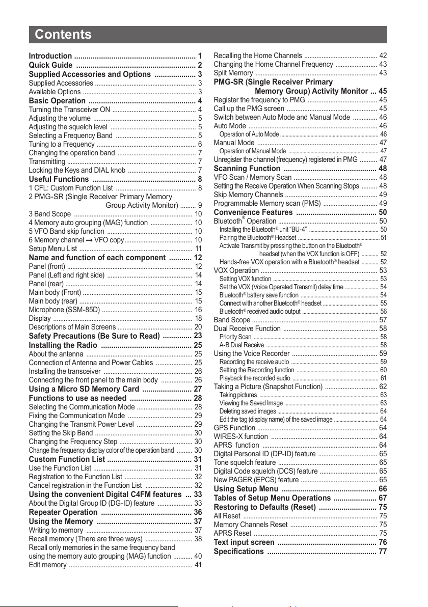
Introduction ........................................................... 1
Quick Guide .......................................................... 2
Supplied Accessories and Options .................... 3
Supplied Accessories .......................................................... 3
Available Options ................................................................. 3
Basic Operation .................................................... 4
Turning the Transceiver ON ................................................ 4
Adjusting the volume ........................................................... 5
Adjusting the squelch level ................................................. 5
Selecting a Frequency Band .............................................. 5
Tuning to a Frequency ......................................................... 6
Changing the operation band ............................................. 7
Transmitting .......................................................................... 7
Locking the Keys and DIAL knob ....................................... 7
Useful Functions .................................................. 8
1 CFL: Custom Function List .............................................. 8
2
PMG-SR (Single Receiver Primary Memory
Group Activity Monitor)
......... 9
3 Band Scope .................................................................... 10
4 Memor y auto grouping (MAG) function ........................ 10
5 VFO Band skip function ................................................. 10
6 Memor y channel VFO copy ....................................... 10
Setup Menu List ................................................................. 11
Name and function of each component ........... 12
Panel (front) ........................................................................ 12
Panel (Left and right side) ................................................. 14
Panel (rear) ......................................................................... 14
Main body (Front) ............................................................... 15
Main body (rear) ................................................................. 15
Microphone (SSM-85D) .................................................... 16
Display ................................................................................ 18
Descriptions of Main Screens ........................................... 20
Safety Precautions (Be Sure to Read
) .............. 23
Installing the Radio ............................................ 25
About the antenna ............................................................. 25
Connection of Antenna and Power Cables ..................... 25
Installing the transceiver ................................................... 26
Connecting the front panel to the main body .................. 26
Using a Micro SD Memory Card ........................ 27
Functions to use as needed .............................. 28
Selecting the Communication Mode ................................ 28
Fixing the Communication Mode ..................................... 29
Changing the Transmit Power Level ................................ 29
Setting the Skip Band ........................................................ 30
Changing the Frequency Step .......................................... 30
Change the frequency display color of the operation band
......... 30
Custom Function List ......................................... 31
Use the Function List ......................................................... 31
Registration to the Function List ....................................... 32
Cancel registration in the Function List ........................... 32
Using the convenient Digital C4FM features ... 33
About the Digital Group ID (DG-ID) feature .................... 33
Repeater Operation ............................................ 36
Using the Memory .............................................. 37
Writing to memory ............................................................. 37
Recall memory ( There are three ways) ........................... 38
Recall only memories in the same frequency band
using the memory auto grouping (MAG) function ........... 40
Edit memor y ....................................................................... 41
Recalling the Home Channels .......................................... 42
Changing the Home Channel Frequency ........................ 43
Split Memory ...................................................................... 43
PMG-SR (Single Receiver Primary
Memory Group) Activity Monitor ... 45
Register the frequency to PMG ........................................ 45
Call up the PMG screen .................................................... 45
Switch between Auto Mode and Manual Mode .............. 46
Auto Mode .......................................................................... 46
Operation of Auto Mode ....................................................................... 46
Manual Mode ..................................................................... 47
Operation of Manual Mode ................................................................. 47
Unregister the channel (frequency) registered in PMG
.......... 47
Scanning Function ............................................. 48
VFO Scan / Memory Scan ................................................ 48
Setting the Receive Operation When Scanning Stops
......... 48
Skip Memory Channels ..................................................... 49
Programmable Memory scan (PMS) ............................... 49
Convenience Features ....................................... 50
Bluetooth® Operation ......................................................... 50
Installing the Bluetooth® unit “BU-4” .................................................. 50
Pairing the Bluetooth
Activate Transmit by pressing the but ton on the Bluetooth
headset (when the VOX func tion is OFF) ............ 52
Hands-free VOX operation with a Bluetooth® headset
®
Headset ........................................................... 51
®
............ 52
VOX Operation ................................................................... 53
Setting VOX function ............................................................................ 53
Set the VOX (Voice Operated Transmit) delay time ........................ 54
®
batter y save function ........................................................ 54
Bluetooth
Connect with another Bluetooth
®
received audio output ....................................................... 56
Bluetooth
®
headset ........................................ 55
Band Scope ........................................................................ 57
Dual Receive Function ...................................................... 58
Priority Scan .......................................................................................... 58
A-B Dual Receive ................................................................................. 58
Using the Voice Recorder ................................................. 59
Recording the receive audio ............................................................... 59
Setting the Recording function ........................................................... 60
Playback the recorded audio .............................................................. 61
Taking a Picture (Snapshot Function) .............................. 62
Taking pictures ...................................................................................... 63
Viewing the Saved Image .................................................................... 63
Deleting saved images ......................................................................... 64
Edit the tag (display name) of the saved image ................................ 64
GPS Function ..................................................................... 64
WIRES-X function ............................................................. 64
APRS function .................................................................. 64
Digital Personal ID (DP-ID) feature .................................. 65
Tone squelch feature ......................................................... 65
Digital Code squelch (DCS) feature ................................. 65
New PAGER (EPCS) feature ............................................ 65
Using Setup Menu .............................................. 66
Tables of Setup Menu Operations ..................... 67
Restoring to Defaults (Reset) ............................ 75
All Reset ............................................................................. 75
Memor y Channels Reset .................................................. 75
APRS Reset ....................................................................... 75
Text input screen ................................................ 76
Specifications ..................................................... 77
Page 3

Introduction
Features of the Yaesu FTM-200DR/DE Transceiver.
Digital communication using Yaesu (C4FM (Quaternary FSK) system)
m
Equipped with AMS (Automatic Mode Select) feature that automatically selects the
m
analog FM or the C4FM digital modes, according to the signal of the other station.
The Custom Function List (CFL) can be personalized by registering frequently used
m
functions (up to 8) from the 124 items Setup Menu. Functions and setting values are
MENU
then displayed in a list with one-touch operation of the [F
select and use the function with the DIAL knob.
The Single Receiver Primary Memory Group Activity Monitor (PMG-SR) function
m
can register up to 5 channels with the receive frequencies of the VFO or memory
channels by simply pressing and holding the [PMG
PW
to scan the registered frequencies and display the reception status (signal strength)
in a real time bar graph. In auto mode, any channel with a signal is automatically
stopped and received. When operating on the currently selected channel, you can
press the PTT key or press the dial to switch to manual mode and fix the channel for
communication. When there is no signal in the selected channel, it scans again and
displays the reception status (signal strength) in real time.
With Memory Channel Band Auto Grouping (MAG). The memory channels are
m
automatically categorized in each band, so that memory channels can be quickly recalled.
The DG-ID (Digital Group ID) feature, and the Group Monitor (GM) feature enable
m
automatically locating, and communicating with other stations that are within contact
range and have the matching DG-ID number, (00 to 99).
Two-inch QVGA full-color TFT display with high-brightness and wide viewing angle.
m
Wide-band reception (108 MHz to 999.99 MHz) (USA Cellular Blocked)
m
Built-in GPS unit permits display of the current location and heading information
m
Installation of the optional Bluetooth® BU-4 unit permits hands-free communication
m
using the optional Bluetooth
Large-capacity 1104 memory channels
m
3W Audio Power Speaker with a jack for the optional external speaker
m
Heavy Duty-Heat Sink with FACC (Funnel Air-Convection Conductor)
m
High speed band scope that displays 61 channels
m
Smart Navigation function
m
Snapshot function (optional camera/microphone MH-85A11U is required)
m
WiRES-X Portable Digital Node or Fixed Node with HRI-200
m
Equipped with digital GM (Group Monitor) function
m
Ready for APRS
m
Digital Personal ID (DP-ID) feature
m
Compatible with microSD memory cards
m
Thank you for purchasing the FTM-200DR/DE Transceiver. We urge you to read this manual in its entirety, and
also the Advance Manual (available for download on the Yaesu website), to gain a full understanding of the
amazing capability of the exciting new FTM-200DR/DE Transceiver.
WIRES-X, GM function and APRS instruction manuals are not included in the product package. They are
available and may be downloaded from the Yaesu.com website.
®
communication with world standard 1200 / 9600bps AX25 modem
®
headset SSM-BT10 or a commercially available product.
] key. Or you can easily
] key. Press the [PMG PW] key
1
Page 4
Quick Guide
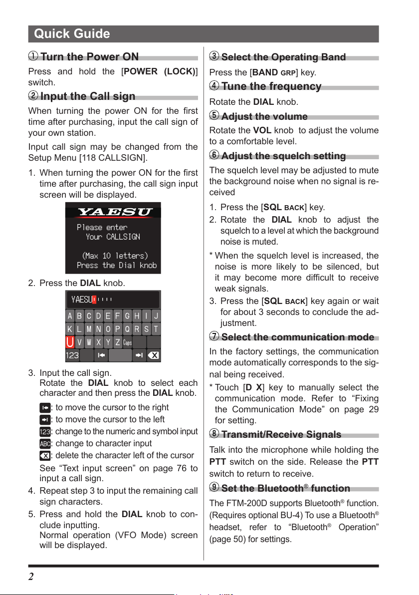
Turn the Power ON
Press and hold the [POWER (LOCK)]
switch.
Input the Call sign
When turning the power ON for the first
time after purchasing, input the call sign of
your own station.
Input call sign may be changed from the
Setup Menu [118 CALLSIGN].
1. When turning the power ON for the first
time after purchasing, the call sign input
screen will be displayed.
Please enter
Your CALLSIGN
(Max 10 letters)
Press the Dial knob
2. Press the DIAL knob.
3. Input the call sign.
Rotate the DIAL knob to select each
character and then press the DIAL knob.
:
to move the cursor to the right
:
to move the cursor to the left
:
change to the numeric and symbol input
:
change to character input
:
delete the character left of the cursor
See “Text input screen” on page 76 to
input a call sign.
4. Repeat step 3 to input the remaining call
sign characters.
5. Press and hold the DIAL knob to con-
clude inputting.
Normal operation (VFO Mode) screen
will be displayed.
Select the Operating Band
Press the [BAND GRP] key.
Tune the frequency
Rotate the DIAL knob.
Adjust the volume
Rotate the VOL knob to adjust the volume
to a comfortable level.
Adjust the squelch setting
The squelch level may be adjusted to mute
the background noise when no signal is re-
ceived
1. Press the [SQL
ate the DIAL knob to adjust the
2. Rot
squelch to a level at which the background
noise is muted.
* When the squelch level is increased, the
noise is more likely to be silenced, but
it may become more difficult to receive
weak signals.
3. Press the [SQL
for about 3 seconds to conclude the ad-
justment.
BACK] key.
BACK] key again or wait
Select the communication mode
In the factory settings, the communication
mode automatically corresponds to the sig-
nal being received.
* Touch [D X] key to manually select the
communication mode. Refer to “Fixing
the Communication Mode” on page 29
for setting.
Transmit/Receive Signals
Talk into the microphone while holding the
PTT switch on the side. Release the PTT
switch to return to receive.
Set the Bluetooth® function
The FTM-200D supports Bluetooth® function.
(Requires optional BU-4) To use a Bluetooth
headset, refer to “Bluetooth
(page 50) for settings.
®
Operation”
®
2
Page 5

Supplied Accessories and Options
Supplied Accessories
• DTMF microphone SSM-85D
• DC power cable (with fuse attached)
• Control cable
• Control cable 10ft (3m)
• Bracket for main body (with mounting screws)
• Bracket for the controller
• Mic hanger (with mounting screws)
• USB Cable
• Spare fuse (15A) x2
• Operating Manual (This Manual)
If any item is missing, contact the dealer from which you purchased the transceiver.
Available Options
• Microphone with Snapshot Camera MH-85A11U
• DTMF Microphone SSM-85D
• Microphone MH-42C6J
• Bluetooth
• Bluetooth
• High-Power External Speaker MLS-100
• Voice Guide Unit FVS-2
• Vacuum Cup Mount Bracket for Front Panel Controller MMB-98
• Mic Extension Cable10ft (3m) for MH-85A11U SCU-23
• Mic Extension Kit 10ft (3m) for SSM-85D and MH-42C6J MEK-5
• Control Cable 20ft (6m) SCU-47
• Cloning Cable CT-166
• WIRES-X Connection Cable kit SCU-40
• Data Cable (MDIN10 pin to MDIN6 pin + Dsub9) CT-163
• Data Cable (MDIN10 pin to MDIN6 pin) CT-164
• Data Cable (MDIN10 pin to Open) CT-167
®
Headset SSM-BT10
®
Unit BU-4
3
Page 6

Basic Operation
Turning the Transceiver ON
1. Press and hold the POWER (LOCK) switch to turn the
transceiver ON / OFF.
z Inputting the call sign
1. The first time the transceiver is turned ON after it is
purchased; input your own call sign.
2. Press the DIAL knob to proceed to the call sign input
screen.
• When the transceiver is subsequently turned ON, the
opening screen appears followed by the frequency
screen.
• The input call sign may be changed from the Setup
Menu [118 CALLSIGN].
3. Rotate the DIAL knob, then press it to select each
character.
Please enter
Your CALLSIGN
(Max 10 letters)
Press the Dial knob
: to move the cursor to the right.
: to move the cursor to the left.
: change to the numeric and symbol input
:
delete the character left of the cursor
Up to 10 characters (letters, numbers, and a hyphen) can be entered.
4. Repeat step 3 to input the remaining call sign characters.
5. Press and hold the DIAL knob to conclude inputting.
Normal operating (VFO Mode) screen will be displayed.
4
Page 7
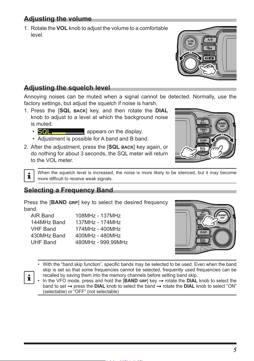
Adjusting the volume
1. Rotate the VOL knob to adjust the volume to a comfortable
level.
Adjusting the squelch level
Annoying noises can be muted when a signal cannot be detected. Normally, use the
factory settings, but adjust the squelch if noise is harsh.
1. Press the [SQL
BACK] key, and then rotate the DIAL
knob to adjust to a level at which the background noise
is muted.
•
appears on the display.
• Adjustment is possible for A band and B band.
2. After the adjustment, press the [SQL
BACK] key again, or
do nothing for about 3 seconds, the SQL meter will return
to the VOL meter.
When the squelch level is increased, the noise is more likely to be silenced, but it may become
more difficult to receive weak signals.
Selecting a Frequency Band
Press the [BAND GRP] key to select the desired frequency
band.
AIR Band 108MHz - 137MHz
144MHz Band 137MHz - 174MHz
VHF Band 174MHz - 400MHz
430MHz Band 400MHz - 480MHz
UHF Band
• With the “band skip function”, specific bands may be selected to be used. Even when the band
skip is set so that some frequencies cannot be selected, frequently used frequencies can be
recalled by saving them into the memory channels before setting band skip.
• In the VFO mode, press and hold the [BAND GRP] key rotate the DIAL knob to select the
band to set press the DIAL knob to select the band rotate the DIAL knob to select “ON”
(selectable) or “OFF” (not selectable)
480MHz - 999.99MHz
5
Page 8
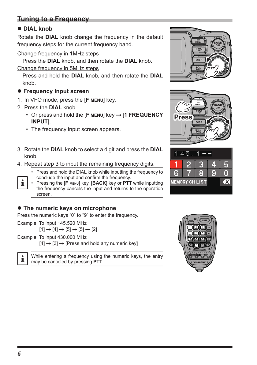
Tuning to a Frequency
z DIAL knob
Rotate the DIAL knob change the frequency in the default
frequency steps for the current frequency band.
Change frequency in 1MHz steps
Press the DIAL knob, and then rotate the DIAL knob.
Change frequency in 5MHz steps
Press and hold the DIAL knob, and then rotate the DIAL
knob.
z Frequency input screen
1. In VFO mode, press the [F MENU] key.
2. Press the DIAL knob.
• Or press and hold the [F
INPUT].
• The frequency input screen appears.
3. Rotate the DIAL knob to select a digit and press the DIAL
knob.
4. Repeat step 3 to input the remaining frequency digits.
• Press and hold the DIAL knob while inputting the frequency to
conclude the input and confirm the frequency.
• Pressing the [
the frequency cancels the input and returns to the operation
screen.
F MENU
MENU] key [1 FREQUENCY
] key, [BACK] key or PTT while inputting
Press
z The numeric keys on microphone
Press the numeric keys “0” to “9” to enter the frequency.
Example: To input 145.520 MHz
[1]
Example: To input 430.000 MHz
[4]
While entering a frequency using the numeric keys, the entry
may be canceled by pressing PTT.
[4] [5] [5] [2]
[3] [Press and hold any numeric key]
6
Page 9

Changing the operation band
Two operational bands are displayed on the top and bottom. The upper display band can
be changed by operating the frequency and radio wave format.
1. Each time the [A/B] key is pressed, the operating band
switches between “A band” and “B band”.
The upper display is called the “operating band”, and the
lower display is called the “sub band”.
The operating band signals and sub-band signals cannot be
received simultaneously.
Transmitting
1. While pressing and holding PTT, speak into the microphone.
2. Release the PTT to return to receive. The receive mode is indicated by the color of the
Status Indicator light on the display.
DIGITAL ANALOG
TX RX TX RX
Red Green Red Green
Blue Blue Red Green
In Digital Mode, if a received signal contains a DG-ID different from the DG-ID setting of this
transceiver, the upper green and lower blue lights flash. In FM mode, the upper and lower green
lights flash when receiving a signal containing a tone or DCS different from the squelch setting of
this station.
• If the PTT switch is pressed when a frequency other than the amateur ham radio band is
selected, an alarm tone (beep) will be emitted, “TX PROHIBIT” appears on the display, and
transmit is disabled.
• If transmission is continued for a long period, the transceiver overheats, and the high temperature
protection function is activated. As a result, the transmitting power level is automatically set to
Low Power. If transmission continues while the high temperature protection function is active,
the transceiver will be forcibly returned to the receive mode.
Locking the Keys and DIAL knob
1. Press the [POWER (Lock)] switch, “LOCK” is shown on
the display for one second, the “
display, and then the keys and DIAL knob are locked.
Press the [POWER (Lock)] switch again, “UNLOCK” will
be shown on the Display and the keys and the DIAL
knob are unlocked.
The “
” icon disappears.
The PTT switch and the VOL knob cannot be locked.
” icon appears on the
7
Page 10
Useful Functions
Press and hold: to register
Press: to recall
then Press
DIAL
knob
Press and hold: to cancel registration
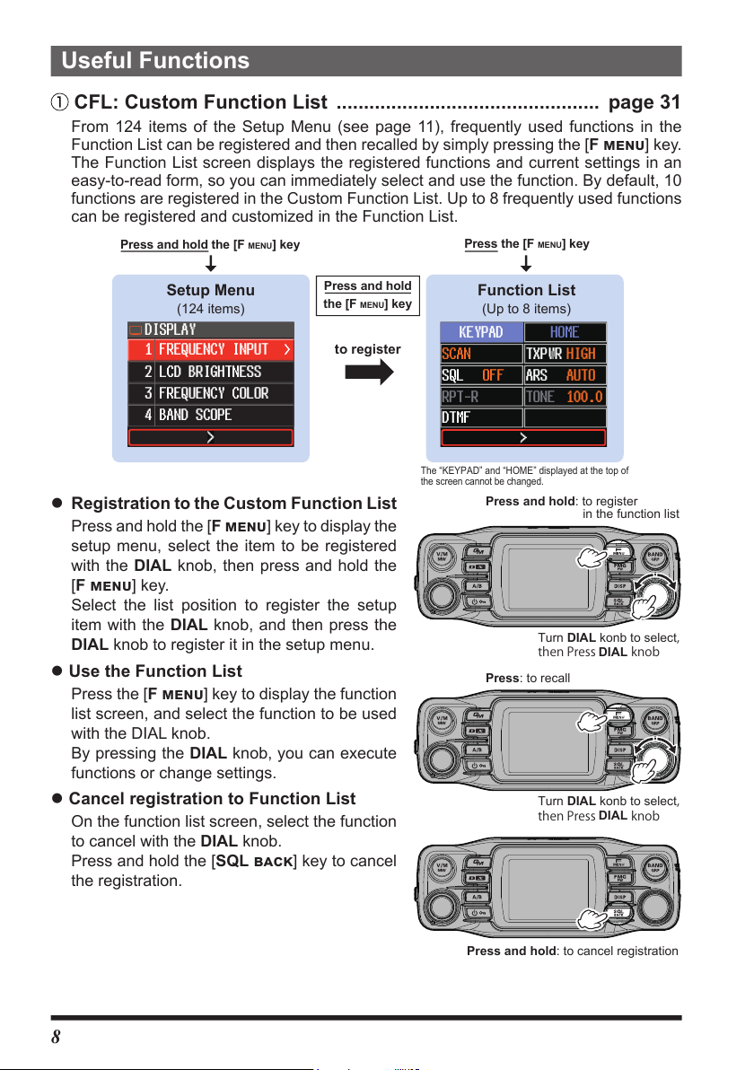
CFL: Custom Function List ................................................ page 31
From 124 items of the Setup Menu (see page 11), frequently used functions in the
Function List can be registered and then recalled by simply pressing the [F menu] key.
The Function List screen displays the registered functions and current settings in an
easy-to-read form, so you can immediately select and use the function. By default, 10
functions are registered in the Custom Function List. Up to 8 frequently used functions
can be registered and customized in the Function List.
Press and hold the [F
MENU
] key
Press the [F
MENU
] key
Setup Menu
(124 items)
Press and hold
MENU
the [F
DISPLAY
1
FREQUENCY INPUT >
2
LCD BRIGHTNESS
3
FREQUENCY COLOR
4
BAND SCOPE
to register
z Registration to the Custom Function List
Press and hold the [F menu] key to display the
setup menu, select the item to be registered
with the DIAL knob, then press and hold the
[F menu] key.
Select the list position to register the setup
item with the DIAL knob, and then press the
DIAL knob to register it in the setup menu.
z Use the Function List
Press the [F menu] key to display the function
list screen, and select the function to be used
with the DIAL knob.
By pressing the DIAL knob, you can execute
functions or change settings.
z Cancel registration to Function List
On the function list screen, select the function
to cancel with the DIAL knob.
Press and hold the [SQL back] key to cancel
the registration.
] key
Function List
(Up to 8 items)
KEYPAD
SCAN
OFF
SQL
RPT-R
HOME
TXPWR HIGH
AUTO
ARS
TONE 100.0
DTMF
The “KEYPAD” and “HOME” displayed at the top of
the screen cannot be changed.
in the function list
Turn DIAL konb to select
then Press
Turn DIAL konb to select
DIAL
knob
,
,
8
Page 11

In auto mode, the PMG channel is continuously scanned, the channel with the signal is
automatically stopped and the signal is heard. When the signal is concluded, the scan
is automatically restarted. To operate on the received channel, press the PTT or DIAL
knob to switch to manual mode, and the channel is fixed for communication.
Press and hold: Register or unregister
Press: Recall or exit PMG
Press DIAL
Press and hold: Unregister
PMG-SR (Single Receiver Primary Memory Group Activity Monitor)
....................... page 45
The PMG function that displays the receive status of registered channels in a bar graph
allows registration of up to 5 channels by pressing and holding the [PMG
PW] key for the
current display frequency of either the VFO or the memory channel. The PMG screen can
be switched to auto mode or manual mode by pressing the DIAL knob.
Current Frequency
(VFO or Memory Channel)
YAESU MUSEN
Press
the [PMG
to call up
to return
PW
] key
In auto mode, the channel with the signal is scanned
and automatically stopped to play the signal. (The
all channel number flashes during scanning)
PMG Screen
(Auto Mode)
YAESU MUSEN
z Register the frequency to PMG
Display the frequency of the VFO or memory
channel, then press and hold the [PMG
PW]
key. The frequency is registered in PMG and
the PMG screen is displayed.
z Display the PMG screen
Press the [PMG PW] key to display the PMG
screen.
Press the DIAL knob to switch between Auto
Mode and Manual Mode.
Auto Mode:
Scans and automatically stops at the channel
with a signal and outputs the received audio.
During output, the bar graphs of the other chan-
nels hold the last reception status and pause.
When there is no signal, scanning is resumed
knob to switch Auto Mode / Manual Mode
Rotate DIAL knob to select
and the receive status is displayed in real time.
(The channel number flashes during scanning
and there is no audio from the speaker.)
Manual Mode:
It is fixed to the channel selected by the DIAL
knob, and when there is a signal, the received
audio is output.
When there is no signal on the selected channel,
it scans and displays the receive status of other
channels in real time. (Even if there is a signal
on another channel, the received audio is not
output.)
z Cancel the frequency registered in PMG
Select a channel on the PMG screen
and press and hold the [PMG
PW] key.
9
Page 12

Band Scope .......................................................................... page 57
Press: Displays the band scope
Press: Select the band to display
(AIRBand)
memory channel
Press and hold: Display the band
Press DIAL to select ON / OFF
Press and hold: Copy to VFO
The receive status (signal strength) of the channels before and after the current frequency
can be displayed as a bar graph, whether in VFO mode or in memory mode.
Press the [DISP] key to display the band
scope screen. When you set the channel
with the signal you want to receive to the
center with the DIAL knob, the scope display
pauses and the received audio is played.
When there is no signal, the scope display is
automatically resumed.
Memory auto grouping (MAG) function ............................ page 40
Memory channels can be automatically grouped and recalled for each band.
Press the [BAND
In the memory mode, each time the [BAND
key is pressed, only memory channels of the
specified frequency band are automatically
recalled as a group, as shown below:
GRP] key in memory mode.
GRP]
in memory mode
All memory channels
174MHz - 400MHz
480 MHz - 999.995MHz
400MHz-480MHz
memory channel
108MHz - 137MHz
memory channel
137MHz-174MHz
memory channel
VFO Band skip function ..................................................... page 30
Bands that are not normally used can be skipped when the [BAND GRP] key is pressed.
In VFO mode, press and hold the [BAND
key, select the band you want to set with the
GRP]
select screen
DIAL knob, and press the DIAL knob.
Then turn the DIAL knob to set “ON”
(selectable) / “OFF” (not selectable).
You can still recall from All Memory Channels
a frequency that is saved in the band set to
be skipped.
Turn DIAL to select a band
Memory channel VFO copy ............................................. page 39
Transfers the recalled memory channel to the VFO with one-touch operation.
Press and hold the [BAND
recalling a memory channel to transfer the
memory channel information to the VFO and
switch to VFO mode.
GRP] key while
in memory mode
10
Page 13
Setup Menu List
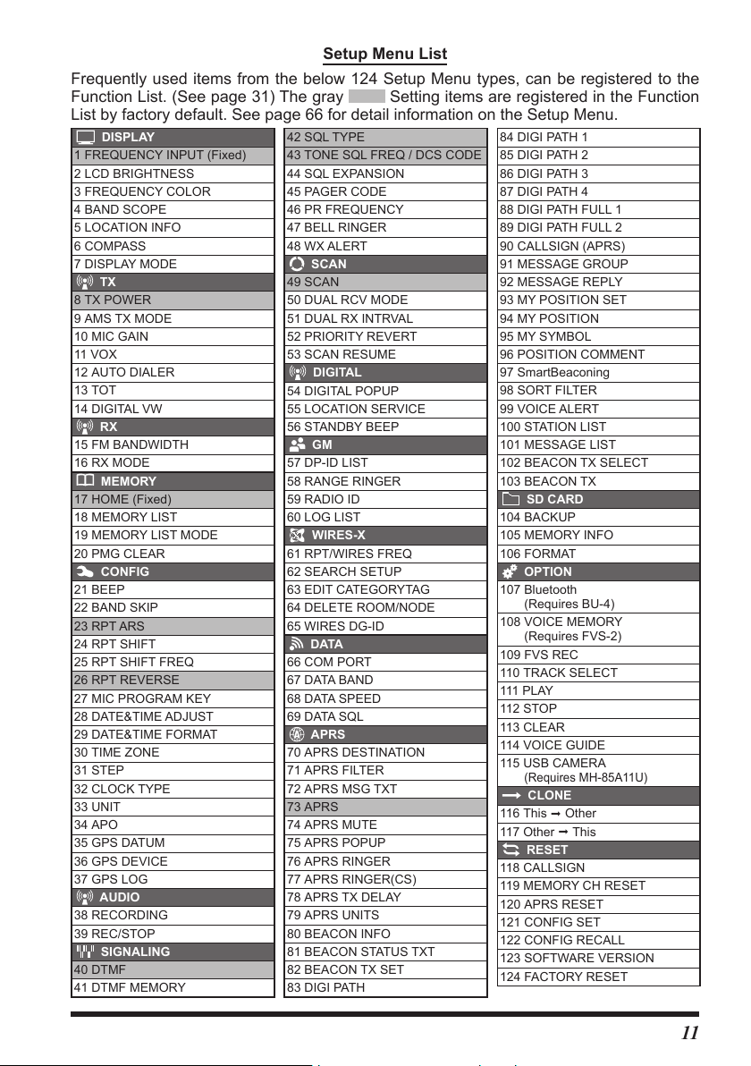
Frequently used items from the below 124 Setup Menu types, can be registered to the
Function List. (See page 31) The gray
Setting items are registered in the Function
List by factory default. See page 66 for detail information on the Setup Menu.
DISPLAY
1 FREQUENCY INPUT (Fixed)
2 LCD BRIGHTNESS
3 FREQUENCY COLOR
4 BAND SCOPE
5 LOCATION INFO
6 COMPASS
7 DISPLAY MODE
TX
8 TX POWER
9 AMS TX MODE
10 MIC GAIN
11 VOX
12 AUTO DIALER
13 TOT
14 DIGITAL VW
RX
15 FM BANDWIDTH
16 RX MODE
MEMORY
17 HOME (Fixed)
18 MEMORY LIST
19 MEMORY LIST MODE
20 PMG CLEAR
CONFIG
21 BEEP
22 BAND SKIP
23 RPT ARS
24 RPT SHIFT
25 RPT SHIFT FREQ
26 RPT REVERSE
27 MIC PROGRAM KEY
28 DATE&TIME ADJUST
29 DATE&TIME FORMAT
30 TIME ZONE
31 STEP
32 CLOCK TYPE
33 UNIT
34 APO
35 GPS DATUM
36 GPS DEVICE
37 GPS LOG
AUDIO
38 RECORDING
39 REC/STOP
SIGNALING
40 DTMF
41 DTMF MEMORY
42 SQL TYPE
43 TONE SQL FREQ / DCS CODE
44 SQL EXPANSION
45 PAGER CODE
46 PR FREQUENCY
47 BELL RINGER
48 WX ALERT
SCAN
49 SCAN
50 DUAL RCV MODE
51 DUAL RX INTRVAL
52 PRIORITY REVERT
53 SCAN RESUME
DIGITAL
54 DIGITAL POPUP
55 LOCATION SERVICE
56 STANDBY BEEP
GM
57 DP-ID LIST
58 RANGE RINGER
59 RADIO ID
60 LOG LIST
WIRES-X
61 RPT/WIRES FREQ
62 SEARCH SETUP
63 EDIT CATEGORYTAG
64 DELETE ROOM/NODE
65 WIRES DG-ID
DATA
66 COM PORT
67 DATA BAND
68 DATA SPEED
69 DATA SQL
APRS
70 APRS DESTINATION
71 APRS FILTER
72 APRS MSG TXT
73 APRS
74 APRS MUTE
75 APRS POPUP
76 APRS RINGER
77 APRS RINGER(CS)
78 APRS TX DELAY
79 APRS UNITS
80 BEACON INFO
81 BEACON STATUS TXT
82 BEACON TX SET
83 DIGI PATH
84 DIGI PATH 1
85 DIGI PATH 2
86 DIGI PATH 3
87 DIGI PATH 4
88 DIGI PATH FULL 1
89 DIGI PATH FULL 2
90 CALLSIGN (APRS)
91 MESSAGE GROUP
92 MESSAGE REPLY
93 MY POSITION SET
94 MY POSITION
95 MY SYMBOL
96 POSITION COMMENT
97 SmartBeaconing
98 SORT FILTER
99 VOICE ALERT
100 STATION LIST
101 MESSAGE LIST
102 BEACON TX SELECT
103 BEACON TX
SD CARD
104 BACKUP
105 MEMORY INFO
106 FORMAT
OPTION
107 Bluetooth
(Requires BU-4)
108 VOICE MEMORY
(Requires FVS-2)
109 FVS REC
110 TRACK SELECT
111 PLAY
112 STOP
113 CLEAR
114 VOICE GUIDE
115 USB CAMERA
(Requires MH-85A11U)
CLONE
116 This Other
117 Other This
RESET
118 CALLSIGN
119 MEMORY CH RESET
120 APRS RESET
121 CONFIG SET
122 CONFIG RECALL
123 SOFTWARE VERSION
124 FACTORY RESET
11
Page 14
Name and function of each component
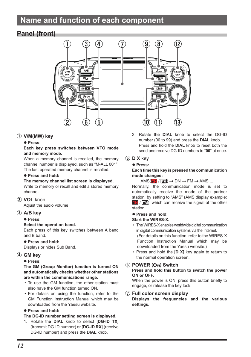
Panel (front)
V/M(MW) key
z Press:
Each key press switches between VFO mode
and memory mode.
When a memory channel is recalled, the memory
channel number is displayed, such as “M-ALL 001”.
The last operated memory channel is recalled.
z Press and hold:
The memory channel list screen is displayed.
Write to memory or recall and edit a stored memory
channel.
VOL knob
Adjust the audio volume.
A/B key
z Press:
Select the operation band.
Each press of this key switches between A band
and B band.
z Press and hold:
Displays or hides Sub Band.
GM key
z Press:
The GM (Group Monitor) function is turned ON
and automatically checks whether other stations
are within the communications range.
• To use the GM function, the other station must
also have the GM function turned ON.
• For details on using the function, refer to the
GM Function Instruction Manual which may be
downloaded from the Yaesu website.
z Press and hold:
The DG-ID number setting screen is displayed.
1. Rotate the DIAL knob to select [DG-ID TX]
(transmit DG-ID number) or [DG-ID RX] (receive
DG-ID number) and press the DIAL knob.
2. Rotate the DIAL knob to select the DG-ID
number (00 to 99) and press the DIAL knob.
Press and hold the DIAL knob to reset both the
send and receive DG-ID numbers to “00” at once.
D X key
z Press:
Each time this key is pressed the communication
mode changes:
Normally, the communication mode is set to
automatically receive the mode of the partner
station, by setting to “AMS” (AMS display example:
/ ), which can receive the signal of the other
station.
z Press and hold:
Start the WIRES-X.
• The WIRES-X enables worldwide digital communication
in digital communication systems via the Internet.
(For details on this function, refer to the WIRES-X
Function Instruction Manual which may be
downloaded from the Yaesu website.)
• Press and hold the [D X] key again to return to
the normal operation screen.
POWER
Press and hold this button to switch the power
ON or OFF.
When the power is ON, press this button briefly to
engage, or release the key lock.
/ ) DN FM AMS ...
AMS(
)
(
Switch
Full color screen display
Displays the frequencies and the various
settings.
12
Page 15

F MENU key
z Press:
Display the “Function List” screen. From the Setup
Menu (see page 66), (Only up to 10 registered
setup items are displayed for quick operation).
KEYPAD
SCAN
OFF
SQL
RPT-R
DTMF
Items other than the “KEYPAD” and “HOME” can be
changed at any time. (see page 31)
Registration / Change:
Press and hold the [F
item to be registered with the DIAL knob press
and hold the [F
Cancel registration:
Rotate the DIAL knob to select the item to cancel the
registration
z Press and hold:
The Setup Menu is displayed. (see page 60)
Rotate the DIAL knob to select an item and press
the DIAL knob to use functions or make settings.
MENU] key
Press and hold the [SQL BACK] key
HOME
TXPWR HIGH
AUTO
ARS
TONE 100.0
APRS OFF
MENU] key select the setup
PMG pw key
z Press:
Displays PMG-SR (Primary Memory Group Activity
Monitor for Single Receiver).
• Press the DIAL knob to switch between auto mode
and manual mode.
• In auto mode, a certain frequency of the signal
is automatically selected and you can hear the
received sound.
• Press the PTT or DIAL knob to switch to manual
mode, and use the DIAL knob to select the
frequency for reception.
• Press again to cancel PMG mode.
z Press and hold:
Register the displayed frequency in PMG.
Press and hold in VFO mode or memory mode to
register the current frequency in PMG.
Up to 5 channels can be registered for PMG
regardless of the frequency band.
(see page 45)
DISP key
z Press:
The scope screen displays a graph showing
the signal strength of a number of channels,
centered on the current VFO frequency or
memory channel. (See page 57)
Press it again to return to the normal screen.
z Press and hold:
Displays the backtrack screen that shows the
distance and direction of the partner station and
permits navigation to a registered point.
SQL BACK key
z Press:
Press this key and then rotate the DIAL knob to
adjust the squelch level.
Annoying noises can be muted when a signal cannot
be detected. Normally, use the factory settings, but
adjust the squelch if noise is harsh.
• On the Function List screen and Setup Menu
screen, the screen returns to the previous screen
currently being operated.
z Press and hold:
Press and hold on the Function List screen to
cancel the registration of the selected item.
BAND GRP key
In VFO mode
z Press:
Each key press canges the operating frequency
band.
Band Selectable Frequency Range
AIR 108MHz - 137MHz
144MHz 137MHz - 174MHz
VHF 174MHz - 400MHz
430MHz 400MHz - 480MHz
UHF 480MHz - 999.99MHz
z Press and hold
Set the band that can be selected by pressing this key.
In memory mode
In Memory mode
z Press:
With the memory auto grouping (MAG) function,
only memory channels in the same frequency band
are automatically recalled as a group.
Group Selectable Memory Channels
All memory channels.
AIR band (108 - 137MHz)memory
channels only.
144MHz band (137 - 174MHz)
memory channels only.
430MHz band (400 - 480MHz)
memory channels only.
174MHz to 400MHz and 480MHz to
999.995MHz Memory channels only
z Press and hold:
Transfers the contents of the recalled memory
channel to the VFO and enters VFO mode.
DIAL knob
Change the frequency or select the memory channel.
• In VFO mode, the frequency may be changed in
1MHz increments after pressing the knob. Tuning
will be in 5MHz increments after pressing and
holding the knob.
• In Memory Mode, press and then turn the knob to
select in 10 channel steps..
• Press the [SQL
to adjust the squelch level.
BACK] key and then turn the knob
13
Page 16
Panel (Left and right side)
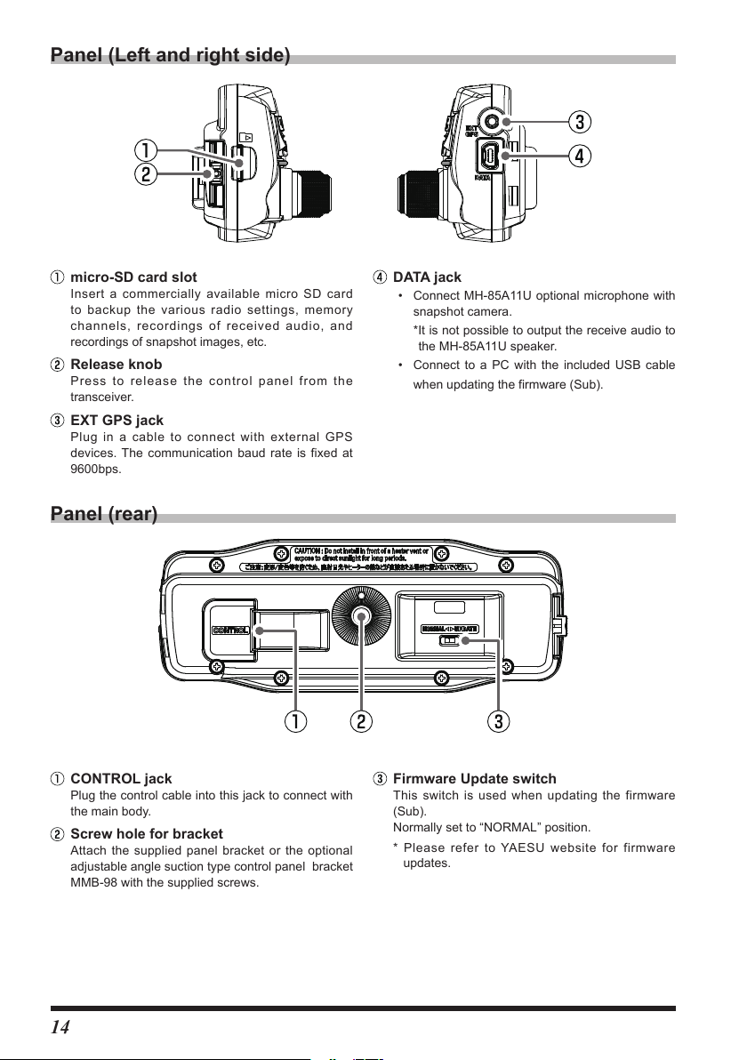
micro-SD card slot
Insert a commercially available micro SD card
to backup the various radio settings, memory
channels, recordings of received audio, and
recordings of snapshot images, etc.
Release knob
Press to release the control panel from the
transceiver.
EXT GPS jack
Plug in a cable to connect with external GPS
devices. The communication baud rate is fixed at
9600bps.
Panel (rear)
CONTROL jack
Plug the control cable into this jack to connect with
the main body.
Screw hole for bracket
Attach the supplied panel bracket or the optional
adjustable angle suction type control panel bracket
MMB-98 with the supplied screws.
DATA jack
• Connect MH-85A11U optional microphone with
snapshot camera.
*It is not possible to output the receive audio to
the MH-85A11U speaker.
• Connect to a PC with the included USB cable
when updating the firmware (Sub).
Firmware Update switch
This switch is used when updating the firmware
(Sub).
Normally set to “NORMAL” position.
* Please refer to YAESU website for firmware
updates.
14
Page 17
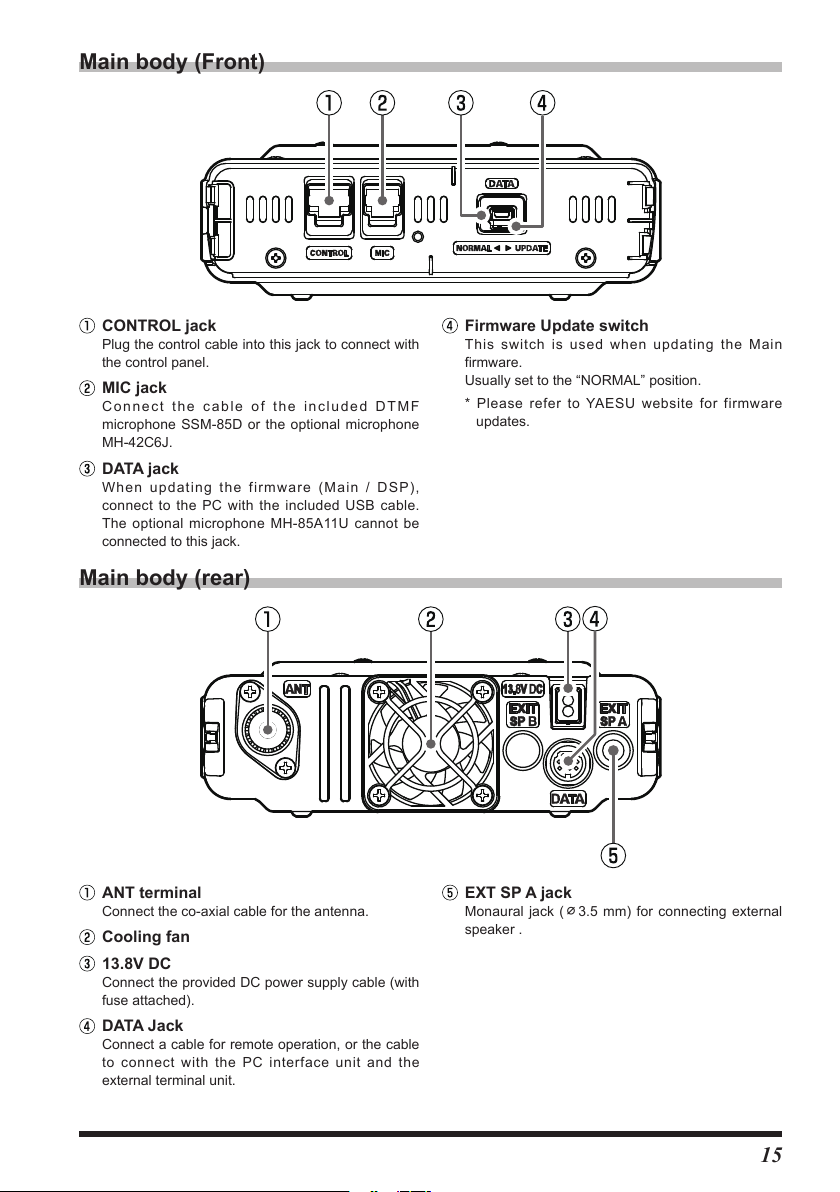
Main body (Front)
CONTROL jack
Plug the control cable into this jack to connect with
the control panel.
MIC jack
Connect the cable of the included DTMF
microphone SSM-85D or the optional microphone
MH-42C6J.
DATA jack
When updating the firmware (Main / DSP),
connect to the PC with the included USB cable.
The optional microphone MH-85A11U cannot be
connected to this jack.
Main body (rear)
ANT terminal
Connect the co-axial cable for the antenna.
Cooling fan
13.8V DC
Connect the provided DC power supply cable (with
fuse attached).
DATA Jack
Connect a cable for remote operation, or the cable
to connect with the PC interface unit and the
external terminal unit.
Firmware Update switch
This switch is used when updating the Main
firmware.
Usually set to the “NORMAL” position.
* Please refer to YAESU website for firmware
updates.
EXT SP A jack
Monaural jack (⌀3.5 mm) for connecting external
speaker .
15
Page 18
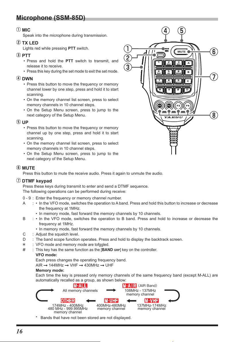
Microphone (SSM-85D)
(AIRBand)
memory channel
MIC
Speak into the microphone during transmission.
TX LED
Lights red while pressing PTT switch.
PTT
• Press and hold the PTT switch to transmit, and
release it to receive.
• Press this key during the set mode to exit the set mode.
DWN
• Press this button to move the frequency or memory
channel lower by one step, press and hold it to start
scanning.
• On the memory channel list screen, press to select
memory channels in 10 channel steps.
• On the Setup Menu screen, press to jump to the
next category of the Setup Menu.
UP
• Press this button to move the frequency or memory
channel up by one step, press and hold it to start
scanning.
• On the memory channel list screen, press to select
memory channels in 10 channel steps.
• On the Setup Menu screen, press to jump to the
next category of the Setup Menu.
MUTE
Press this button to mute the receive audio. Press it again to unmute the audio.
DTMF keypad
Press these keys during transmit to enter and send a DTMF sequence.
The following operations can be performed during receive:
0 - 9 : Enter the frequency or memory channel number.
A : • In the VFO mode, switches the operation to A band. Press and hold this button to increase or decrease
the frequency at 1MHz.
• In memory mode, fast forward the memory channels by 10 channels.
B : • In the VFO mode, switches the operation to B band. Press and hold to increase or decrease the
frequency at 1MHz.
• In memory mode, fast forward the memory channels by 10 channels.
C : Adjust the squelch level.
D : The band scope function operates. Press and hold to display the backtrack screen.
VFO mode and memory mode are tofggled.
:
#
:
This key has the same function as the [BAND GRP] key on the controller.
VFO mode:
Each press changes the operating frequency band.
AIR 144MHz VHF 430MHz UHF
Memory mode:
Each time the key is pressed only memory channels of the same frequency band (except M-ALL) are
automatically recalled as a group, as shown below:
* Bands that have not been stored are not displayed.
16
All memory channels
174MHz - 400MHz
480 MHz - 999.995MHz
400MHz-480MHz
memory channel
108MHz - 137MHz
memory channel
137MHz-174MHz
memory channel
Page 19

Programable keys (P1/P2/P3/P4)
The default function settings of the [P1] / [P2] / [P3] / [P4] keys are shown in the table below.
Key Function Press Press and hold
*
P1
P2 HOME Recalls HOME channel
P3 D_X Selects communication mode Activates the WIRES-X feature
P4 WX (T-CALL) WX (T-CALL: European version)
* The function of the [P1] key is fixed.
The functions of the [P2] / [P3] / [P4] keys can be assigned by the following operations:
1. Press and hold the [F
2. Rotate the DIAL knob to select Set-up menu [CONFIG], then press the DIAL knob.
3. Rotate the DIAL knob to select [27 MIC PROGRAM KEY], then press the DIAL knob.
4. Rotate the DIAL knob to select a key to assign a function [P2] / [P3] / [P4] then press the DIAL knob.
5. Rotate the DIAL knob to select a function (see the table below) then press the DIAL knob.
OFF (Disable the P key)
REC/STOP Voice recording function “REC” / “STOP”
SCAN Starts or stops the scanning function
HOME Recalls the HOME channel
RPT SHIFT Sets the repeater shift direction
REVERSE Reverses the transmit and receive frequencies in repeater mode or split memory.
TX POWER Selects the transmit power output level
SQL OFF Opens the squelch (SQL off)
T-CALL Transmits the T-CALL(1750 Hz)
VOICE Announces the current frequency (requires optional FVS-2)
D_X
WX Switches operation to the Weather Channel Bank
STN LIST Displays the APRS function station list
MSG LIST Displays the message list of the APRS function
REPLY Enters the APRS function reply message write mode
MSG EDIT Enters the APRS function message write mode
DW Operation setting of dual receive function
*
GM
Function Description
GM Function DG-ID setting screen
MENU] key.
Press to select communication mode
Press and hold to activate the WIRES-X feature
17
Page 20
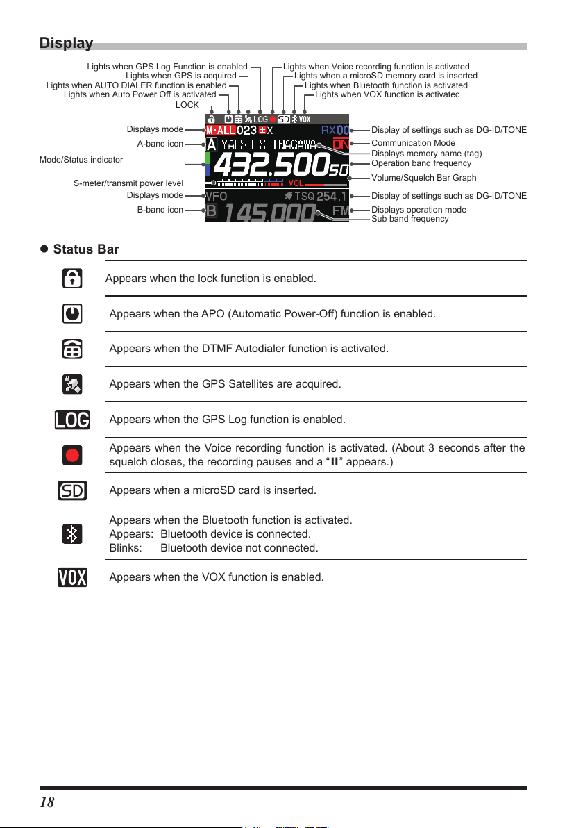
Display
Lights when GPS Log Function is enabled Lights when Voice recording function is activated
Display of settings such as DG-ID/TONE
Display of settings such as DG-ID/TONE
Sub band frequency
Mode/Status indicator
Lights when AUTO DIALER function is enabled
Lights when Auto Power Off is activated
S-meter/transmit power level
Lights when GPS is acquired
LOCK
Displays mode
A-band icon
Displays mode
B-band icon
z Status Bar
Appears when the lock function is enabled.
Appears when the APO (Automatic Power-Off) function is enabled.
Appears when the DTMF Autodialer function is activated.
Appears when the GPS Satellites are acquired.
Appears when the GPS Log function is enabled.
Appears when the Voice recording function is activated. (About 3 seconds after the
squelch closes, the recording pauses and a “II” appears.)
Lights when a microSD memory card is inserted
Lights when Bluetooth function is activated
Lights when VOX function is activated
Communication Mode
Displays memory name (tag)
Operation band frequency
Volume/Squelch Bar Graph
Displays operation mode
18
Appears when a microSD card is inserted.
Appears when the Bluetooth function is activated.
Appears: Bluetooth device is connected.
Blinks: Bluetooth device not connected.
Appears when the VOX function is enabled.
Page 21
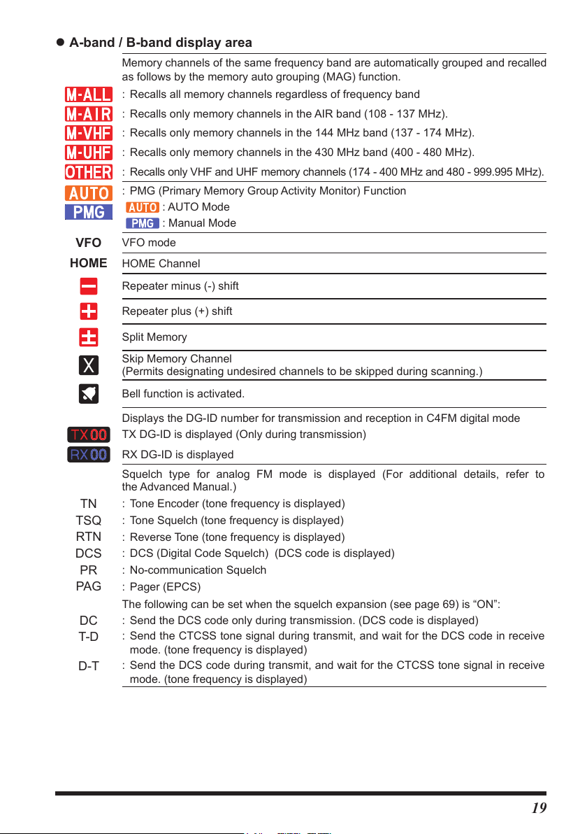
z A-band / B-band display area
Memory channels of the same frequency band are automatically grouped and recalled
as follows by the memory auto grouping (MAG) function.
: Recalls all memory channels regardless of frequency band
: Recalls only memory channels in the AIR band (108 - 137 MHz).
: Recalls only memory channels in the 144 MHz band (137 - 174 MHz).
: Recalls only memory channels in the 430 MHz band (400 - 480 MHz).
: Recalls only VHF and UHF memory channels (174 - 400 MHz and 480 - 999.995 MHz).
: PMG (Primary Memory Group Activity Monitor) Function
: AUTO Mode
: Manual Mode
VFO
HOME
TN
TSQ
RTN
DCS
PR
PAG
DC
T-D
D-T
VFO mode
HOME Channel
Repeater minus (-) shift
Repeater plus (+) shift
Split Memory
Skip Memory Channel
(Permits designating undesired channels to be skipped during scanning.)
Bell function is activated.
Displays the DG-ID number for transmission and reception in C4FM digital mode
TX DG-ID is displayed (Only during transmission)
RX DG-ID is displayed
Squelch type for analog FM mode is displayed (For additional details, refer to
the Advanced Manual.)
: Tone Encoder (tone frequency is displayed)
: Tone Squelch (tone frequency is displayed)
: Reverse Tone (tone frequency is displayed)
: DCS (Digital Code Squelch) (DCS code is displayed)
: No-communication Squelch
: Pager (EPCS)
The following can be set when the squelch expansion (see page 69) is “ON”:
: Send the DCS code only during transmission. (DCS code is displayed)
: Send the CTCSS tone signal during transmit, and wait for the DCS code in receive
mode. (tone frequency is displayed)
: Send the DCS code during transmit, and wait for the CTCSS tone signal in receive
mode. (tone frequency is displayed)
19
Page 22

Displays the operating mode (Digital modes are indicated by a red icon):
: FM (Analog) mode
: V/D mode (Simultaneous voice and data communication mode)
: Voice FR mode (Voice full-rate mode)
: Data FR mode (High speed data communication mode)
: AMS (Automatic Mode Select) FM (Analog) mode
: AMS (Automatic Mode Select) DN mode
: AMS (Automatic Mode Select) VW mode
: AMS (Automatic Mode Select) DW mode
*When AMS (Automatic Mode Select) function is activated, the indicator is shown
with a bar appearing above the mode. The transceiver automatically switches to the
DW mode during image transmission.
: S meter (Displays received signal strength in 10 levels)
: PO meter (Displays transmit output in 3 levels when transmitting)
: Volume level
: SQL level
Descriptions of Main Screens
z Normal screen (VFO screen)
A-band and B-band are shown at the top and bottom of
the display.
• The band displayed on the top of the screen is operat-
ing band.
• Press and hold the [
display off.
NOTE: The A-band and B-band cannot be received at
the same time.
] key to turn the Sub Band
A/B
z Band Scope screen
Press the [DISP] key to display the Band Scope screen.
The strengths of received signals above and below the current frequency or memory
channel are shown in a bar graph while sweeping at high speed. The audio of the
center frequency is heard without interruption.
• Rotate the DIAL knob to change the center frequency
or memory channel.
• In VFO mode 61 or 31channles can be searched. In
memory mode 21 or 11 channels can be searched by
the Band Scope (See page 57)
20
Page 23

z Function List screen
DISPLAY
Press the [F menu] key to display the "Function List" screen that displays only the registered
items from the Setup Menu (see page 66). To return to the normal operation screen from
the Function List, press a key other than the power switch or PTT.
KEYPAD
SCAN
SQL
RPT-R
DTMF
OFF
HOME
TXPWR HIGH
AUTO
ARS
TONE 100.0
APRS OFF
By default, the following 10 steup items are registered in
the Function List. Setup Menu items can be registered,
canged, or canceled at any time.
1 FREQUENCY INPUT (FIXED
49 SCAN 8 TX POWER
42 SQL TYPE 23 RPT ARS
26 RPT REVERSE 43 TONE SQL FRQ / DCS CODE
40 DTMF 73 APRS
NOTE: The KEYPAD and HOME cannot be changed or unregistered.
※
23 HOME (FIXED
)
※
)
z Setup Menu screen
Press and hold the [F MENU] key to display the Setup Menu screen. The Setup Menu
allows selecting various functions from the displayed list and then setting the parame-
ters of each function according individual preferences.
To return to the normal operation screen from the Setup
1
FREQUENCY INPUT >
2
LCD BRIGHTNESS
3
FREQUENCY COLOR
4
BAND SCOPE
Menu, press a key other than the power switch or PTT.
>
z BACKTRACK screen
Press and hold the [DISP] key to display the Backtrack screen.
• Real-time navigation function
Displays the position and direction of the contact station in real time during
communication in C4FM digital DN mode (The transmission of the contact station
must contain GPS location information). It is also possible to configure the display to
show the traveling direction of your own station and the distance to the destination.
• BACKTRACK function
Register up to three locations (“«”, “L1”, “L2”), such as the departure point or the
current location of another station, then display in real time, and navigate the distance
and direction to the registered location from the current location.
• Displays the position of other stations (“ ” icon is
displayed).
[F(SETUP)] [MEM] [«], [L1], [L2]
Stores the current position of the other station.
• The “ ”
icon indicates travel direction of this
station.
[F(SETUP)] [MEM] [«], [L1], [L2]
Stores the current position of this station.
• [F(SETUP)] [«], [L1], [L2]
Start navigation to the registered point.
21
Page 24

z GPS Information screen
Press and hold [F MENU] [7 DISPLAY MODE] [GPS INFORMATION]
Displays the acquired GPS satellites and related information.
The following information is displayed:
• Direction and elevation of satellites
• Current latitude and longitude
• Local Time
z Altitude screen
Press and hold [F MENU] [7 DISPLAY MODE] [ALTITUDE]
The altitude versus the moving distance is displayed in a graph using the GPS signal.
z TIMER/CLOCK screen
Press and hold [F MENU] [7 DISPLAY MODE] [TIMER/CLOCK]
CLOCK, LAP timer and Countdown timer functions are available.
About this manual
The following notation is also used in this manual.
This icon indicates cautions and information that should be read.
This icon indicates notes, tips and information that should be read.
PLEASE NOTE: Due to product improvements, some of the illustrations in the instruction manual
may differ from the actual product.
22
Page 25

Safety Precautions (Be Sure to Read
)
Be sure to read these important precautions, and use this product safely.
Yaesu is not liable for any failures or problems caused by the use or misuse of this product by the pur-
chaser or any third party. Also, Yaesu is not liable for damages caused through the use of this product by
the purchaser or any third party, except in cases where ordered to pay damages under the laws.
Types and meanings of the marks
DANGER
WARNING
CAUTION
This mark indicates an imminently hazardous situation, which, if not
avoided, could result in death or serious injury.
This mark indicates a potentially hazardous situation, which, if not avoid-
ed, could result in death or serious injury.
This mark indicates a potentially hazardous situation, which, if not avoided,
may result in minor or moderate injury or only property damage.
Types and meanings of symbols
These symbols signify prohibited actions, which must not be done to use this product safely.
For example: indicates that the product should not be disassembled.
These symbols signify required actions, which must be done to use this product safely. For
example:
indicates that the power plug should be disconnected.
DANGER
Do not use the device in “regions or aircraft and
vehicles where its use is prohibited” such as in
hospitals and airplanes.
This may exert an impact on electronic and medical
devices.
Do not use this product while driving or riding a
motorbike. This may result in accidents.
Make sure to stop the car in a safe location first
before use if the device is going to be used by the
driver.
Do not operate the device when flammable gas
is generated.
Doing so may result in fire and explosion.
Never touch the antenna during transmission.
This may result in injury, electric shock and equip-
ment failure.
Do not transmit in crowded places in consider-
ation of people who are fitted with medical devic-
es such as heart pacemakers.
Electromagnetic waves from the device may affect
the medical device, resulting in accidents caused by
malfunctions.
When an alarm goes off with the external anten-
na connected, cut Off the power supply to this
radio immediately and disconnect the external
antenna from this radio.
If not, this may result in fire, electric shock and equip-
ment failure.
Do not touch any liquid leaking from the liquid
display with your bare hands.
There is a risk of chemical burns occurring when
the liquid comes into contact with the skin or gets
into the eyes.
immediately.
In this case, seek medical treatment
WARNING
Do not use voltages other than the specified power
supply voltage.
Doing so may result in fire and electric shock.
Do not transmit continuously for long periods of time.
This may cause the temperature of the main body
to rise and result in burns and failures due to over-
heating.
Do not dismantle or modify the device.
This may result in injury, electric shock and equip-
ment failure.
Do not handle the power plug and connector etc.
with wet hands. Also do not plug and unplug the
power plug with wet hands.
This may result in injury, liquid leak, electric shock
and equipment failure.
When smoke or strange odors are emitted from
the radio, turn Off the power and disconnect the
power cord from the socket.
This may result in fire, liquid leak, overheating, dam-
age, ignition and equipment failure. Please contact
our company amateur customer support or the retail
store where you purchased the device.
Keep the power plug pins and the surrounding
area clean at all times.
Contamination may result in fire, liquid leak, over-
heating, breakage, ignition etc.
Disconnect the power cord and connection ca-
bles before incorporating items sold separately
or replacing the fuse.
This may result in fire, electric shock and equipment
failure.
23
Page 26

Never cut off the fuse holder of the DC power cord.
This may cause short-circuiting and result in ignition
and fire.
Do not use fuses other than those specified.
Doing so may result in fire and equipment failure.
Do not allow metallic objects such as wires, or
water to get inside the product.
This may result in fire, electric shock and equipment
failure.
Do not place the device in areas that may get wet
easily (e.g. near a humidifier).
This may result in fire, electric shock and equipment
failure.
When connecting a DC power cord, pay due care
not to mix up the positive and negative polarities.
This may result in fire, electric shock and equipment
failure.
Do not use DC power cords other than the one
enclosed or specified.
This may result in fire, electric shock and equipment
failure.
Do not bend, twist, pull, heat and modify the pow-
er cord and connection cables in an unreason-
able manner.
This may cut or damage the cables and result in fire,
electric shock and equipment failure.
CAUTION
Do not place this device near a heating instru-
ment or in a location exposed to direct sunlight.
This may result in deformation and discoloration.
Do not place this device in a location where there
is a lot of dust and humidity.
Doing so may result in fire and equipment failure.
Stay as far away from the antenna as possible
during transmission.
Long-term exposure to electromagnetic radiation
may have a negative effect on the human body.
Do not wipe the case using thinner and benzene etc.
Please use a soft and dry piece of cloth to wipe away
the stains on the case.
Keep out of the reach of small children.
If not, this may result in injuries to children.
Do not put heavy objects on top of the power
cord and connection cables.
This may damage the power cord and connection
cables, resulting in fire and electric shock.
Do not transmit near the television and radio.
This may result in electromagnetic interference.
Do not use optional products other than those
specified by our company.
If not, this may result in equipment failure.
When using the device in a hybrid car or fu-
el-saving car, make sure to check with the car
manufacturer before using.
The device may not be able to receive transmissions
normally due to the influence of noises from the elec-
trical devices (inverters etc.) fitted in the car.
Do not pull the cable when plugging and unplug-
ging the power cord and connection cables.
Please hold the plug or connector when unplugging.
If not, this may result in fire, electric shock and equip-
ment failure.
Refrain from using headphones and earphones
at a loud volume.
Continuous exposure to loud volumes may result in
hearing impairment.
Do not use the device when the power cord and
connection cables are damaged, and when the
DC power connector cannot be plugged in tight-
ly.
Please contact our company amateur customer
support or the retail store where you purchased the
device as this may result in fire, electric shock and
equipment failure.
Follow the instructions given when installing
items sold separately and replacing the fuse.
This may result in fire, electric shock and equipment
failure.
Do not use the device when the alarm goes off.
For safety reasons, please pull the power plug of the
DC power equipment connected to the product out
of the AC socket.
Never touch the antenna as well. This may result
in fire, electric shock and equipment failure due to
thunder.
For safety reasons, switch off the power and pull
out the DC power cord connected to the DC pow-
er connector when the device is not going to be
used for a long period of time.
If not, this may result in fire and overheating.
Do not throw or subject the device to strong im-
pact forces.
This may result in equipment failure.
Do not the put this device near magnetic cards
and video tapes.
The data in the cash card and video tape etc. may
be erased.
Do not turn on the volume too high when using a
headphone or earphone.
This may result in hearing impairment.
Do not place the device on an unsteady or slop-
ing surface, or in a location where there is a lot
of vibration.
The device may fall over or drop, resulting in fire,
injury and equipment failure.
Do not stand on top of the product, and do not
place heavy objects on top or insert objects in-
side it.
If not, this may result in equipment failure.
Do not use a microphone other than those speci-
fied when connecting a microphone to the device.
If not, this may result in equipment failure.
Do not touch the heat radiating parts.
When used for a long period of time, the temperature
of the heat radiating parts will get higher, resulting in
burns when touched.
Do not open the case of the product except when replac-
ing the fuse and when installing items sold separately.
This may result in injury, electric shock and equip-
ment failure.
24
Page 27

Installing the Radio
DC power cable
Fuse holder
Fuse holder
About the antenna
The antenna is an extremely important part for both transmitting and receiving. The
antenna type and its inherent characteristics determine whether the performance of the
transceiver can be fully realized. As such, please note the following:
Use an antenna that is suitable for the installation conditions and application
objective.
Use an antenna that is suitable for the operating frequency band.
Use an antenna and a coaxial cable with a characteristic feed point impedance of
50Ω.
Adjust the VSWR (Voltage Standing Wave Ratio) until it is 1.5 or less for an antenna
with an adjusted impedance of 50Ω.
Keep the coaxial cable routing length as short as possible.
Connection of Antenna and Power Cables
Please follow the outline in the illustration regarding the proper connection of antenna
coaxial cables and Power Supply.
Cautions
• Do not use a DC power supply cable other than the one that is provided.
• Do not use the DC power supply cable with the fuse holder cut off.
• Use an external power source capable of supplying DC 13.8 V, a current capacity of 15 A or more.
Antenna
Antenna
DC power cable
(supplied)
DC12 V battery
Red
Black
(supplied)
Red
Black
Direct current
13.8 V DC power supply
30
25
Page 28
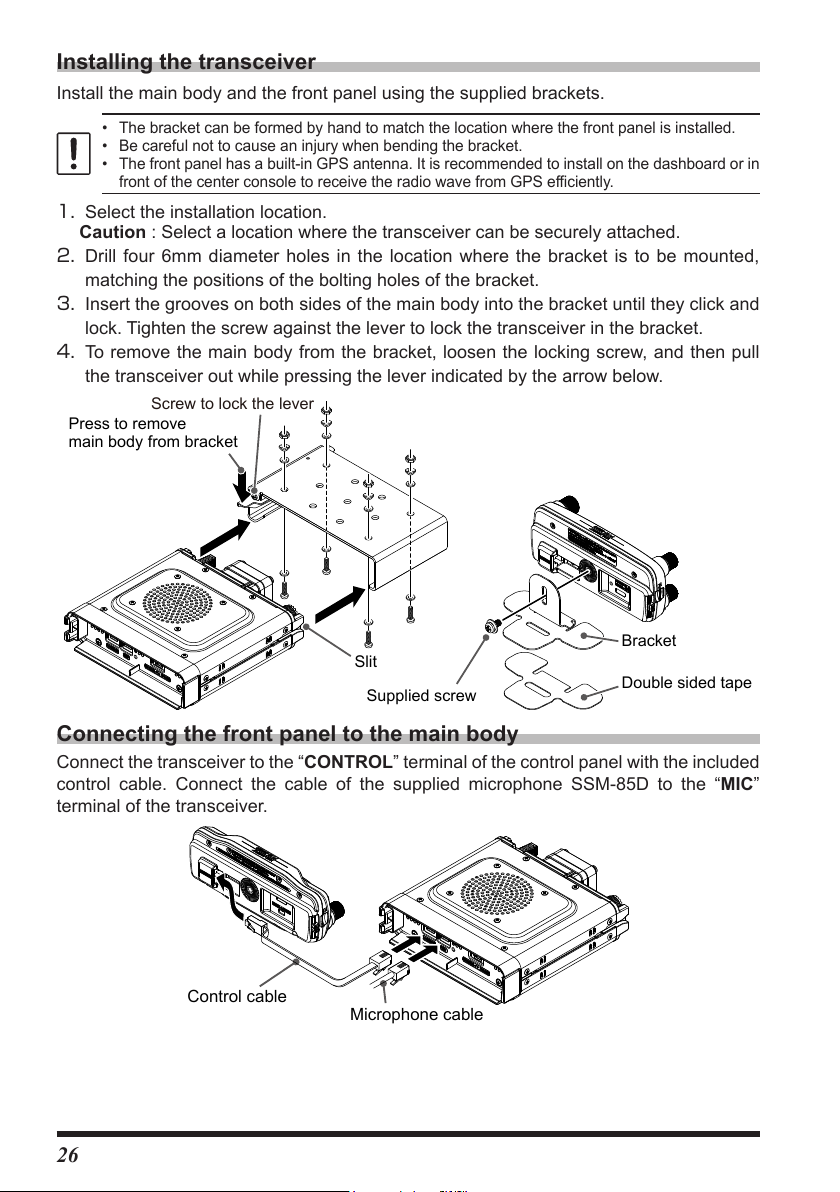
Installing the transceiver
Double sided tape
Screw to lock the lever
Microphone cable
Control cable
Install the main body and the front panel using the supplied brackets.
• The bracket can be formed by hand to match the location where the front panel is installed.
• Be careful not to cause an injury when bending the bracket.
• The front panel has a built-in GPS antenna. It is recommended to install on the dashboard or in
front of the center console to receive the radio wave from GPS efficiently.
Select the installation location.
1.
Caution : Select a location where the transceiver can be securely attached.
Drill four 6mm diameter holes in the location where the bracket is to be mounted,
2.
matching the positions of the bolting holes of the bracket.
Insert the grooves on both sides of the main body into the bracket until they click and
3.
lock. Tighten the screw against the lever to lock the transceiver in the bracket.
To remove the main body from the bracket, loosen the locking screw, and then pull
4.
the transceiver out while pressing the lever indicated by the arrow below.
Press to remove
main body from bracket
Bracket
Slit
Supplied screw
Connecting the front panel to the main body
Connect the transceiver to the “CONTROL” terminal of the control panel with the included
control cable. Connect the cable of the supplied microphone SSM-85D to the “MIC”
terminal of the transceiver.
26
Page 29

Using a Micro SD Memory Card
Contact surface
Using a microSD memory card with the transceiver allows the following functions.
• Backing up the transceiver data and information
• Saving memory information
• Voice recording and playback
• Saving image data captured with the optional camera-equipped microphone (MH-85A11U)
• Saving messages downloaded with the GM function or WIRES-X function
• Saving GPS log data
Usable microSD Memory Cards
This transceiver only supports the following capacity of microSD and microSDHD memory
cards.
• 2GB • 4GB • 8GB • 16GB • 32GB
• microSD memory cards formatted on other devices may not properly save information when
used with this transceiver. Format microSD memory cards again with this transceiver when
using memory cards formatted with another device.
• Do not remove the microSD memory card or turn the transceiver Off, while saving data to a
microSD memory card is in progress.
Mounting and Dismounting microSD Memory Card
1. Turn the transceiver OFF.
2. Insert a microSD memory card into the slot on the left
side of the controller.
With the terminal surface of the microSD card facing the
back of the controller, push it in gently until it clicks.
3. Turn the transceiver ON.
When the memory card is properly detected, “
on the display.
” lights
z Removing the microSD memory card
To remove the microSD memory card (inserted in step 2 above), push the memory card
in until a clicking sound is heard, then remove the memory card.
Formatting a Micro SD Memory Card
Format a new microSD memory card following the steps below before use:
• A microSD memory card that was used in another device may not function properly, for example,
it may not be recognized by the FTM-200DR/DE, or reading and writing may take an unusually
long time. Use of the SD Memory Card Formatter provided by the SD Association may improve
this. The SD Memory Card Formatter can be downloaded from this URL (https://www.sdcard.
org/downloads/formatter/index.html).
• Formatting a microSD memory card erases all data saved on it. Before formatting the card, be
sure to check for data and save it before formatting.
1. Press and hold the [
2. Rotate the DIAL knob to select [106 FORMAT], then press the DIAL knob.
“FORMAT?” appears on the LCD.
3. Rotate the DIAL knob to select [OK], then press the DIAL knob.
Initialization starts and “Waiting” appears.
4. When formatting is completed, a beep sounds and “COMPLETED” appears on the LCD.
F MENU
] key.
27
Page 30

Functions to use as needed
Press and hold
Selecting the Communication Mode
z Using AMS (Automatic Mode Select) function
The FTM-200DR/DE transceiver is equipped with the AMS
(Automatic Mode Select) function which automatically
selects the communication mode corresponding to the
received signal.
To utilize the AMS function, press the [D X] key repeatedly
to display “
signal is received, the communication mode is automatically
switched and the communication mode display changes.
*The display differs depending on the received signal.
z Setting the transmit mode when using the AMS function
The AMS function will automatically set the receiver to the mode of the received signal,
but the transmit mode may be fixed regardless of the received mode.
1. Press and hold the [
2. Rotate the DIAL knob to select [9 AMS TX MODE], then
press the DIAL knob.
3. Press the DIAL knob to select the desired transmit mode
as follows:
When set to “TX FM FIXED” or “TX DN FIXED” and the
AMS transmission mode is fixed, the “bar” at the top of the
communication mode icon flashes.
”*, “ ”* or “ ”* on the display. When a
F MENU
] key.
Press
Transmit Mode Transmit Receive
AUTO
(default)
TX FM FIXED
TX DN FIXED
(TX DIGITAL)
Automatically transmits in the com-
munication mode selected by the
AMS function.
Always transmits in the analog FM
mode.
Always transmits in the DN mode.
Automatically selects the receive
mode corresponding to the received
signal.
4. To return to the normal operation screen from the Function List, press a key other than
the power switch or PTT.
28
Page 31
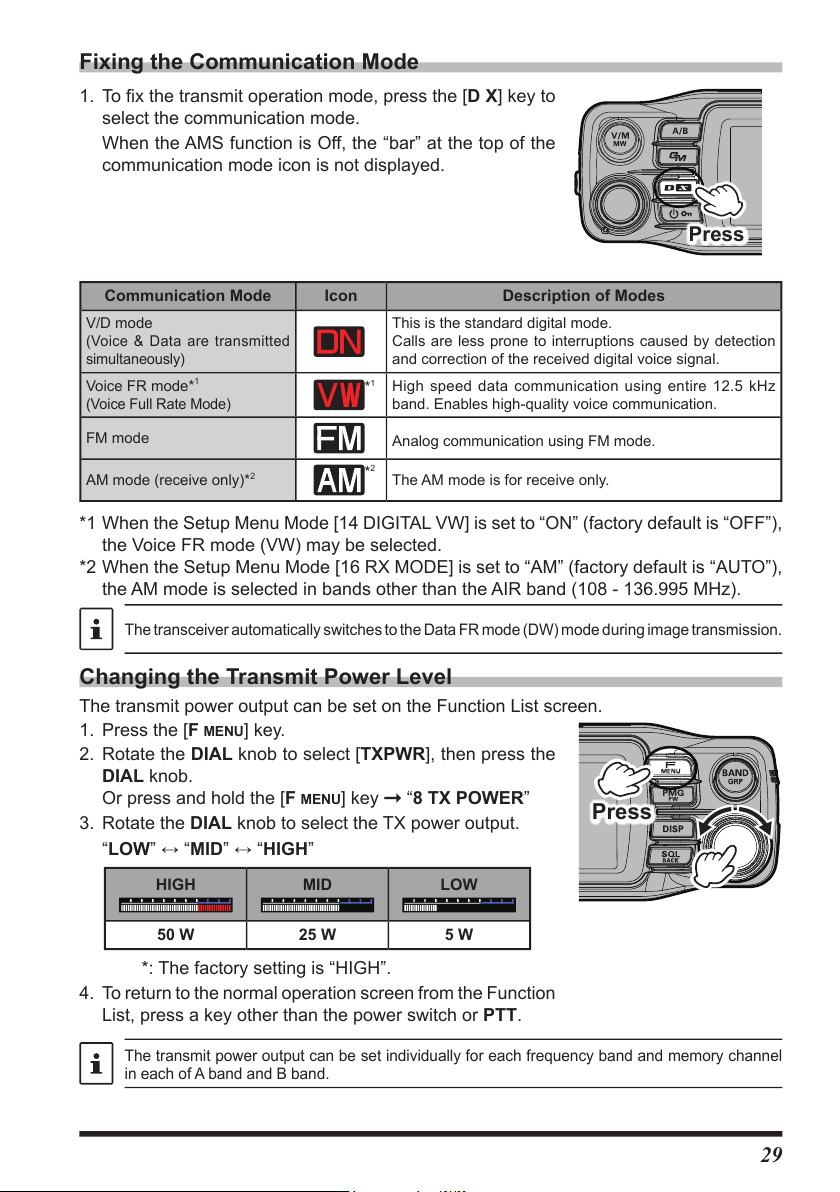
Fixing the Communication Mode
1. To fix the transmit operation mode, press the [D X] key to
select the communication mode.
When the AMS function is Off, the “bar” at the top of the
communication mode icon is not displayed.
Communication Mode Icon Description of Modes
V/D mode
(Voice & Data are transmitted
simultaneously)
Voice FR mode*
(Voice Full Rate Mode)
1
This is the standard digital mode.
Calls are less prone to interruptions caused by detection
and correction of the received digital voice signal.
1
High speed data communication using entire 12.5 kHz
*
band. Enables high-quality voice communication.
Press
FM mode
AM mode (receive only)*
2
Analog communication using FM mode.
2
*
The AM mode is for receive only.
*1 When the Setup Menu Mode [14 DIGITAL VW] is set to “ON” (factory default is “OFF”),
the Voice FR mode (VW) may be selected.
*2 When the Setup Menu Mode [16 RX MODE] is set to “AM” (factory default is “AUTO”),
the AM mode is selected in bands other than the AIR band (108 - 136.995 MHz).
The transceiver automatically switches to the Data FR mode (DW) mode during image transmission.
Changing the Transmit Power Level
The transmit power output can be set on the Function List screen.
F MENU
1. Press the [
2. Rotate the DIAL knob to select [TXPWR], then press the
DIAL knob.
Or press and hold the [
3. Rotate the DIAL knob to select the TX power output.
“LOW” “MID” “HIGH”
HIGH MID LOW
50 W 25 W 5 W
*: The factory setting is “HIGH”.
4. To return to the normal operation screen from the Function
List, press a key other than the power switch or PTT.
] key.
F MENU
] key “8 TX POWER”
Press
The transmit power output can be set individually for each frequency band and memory channel
in each of A band and B band.
29
Page 32

Setting the Skip Band
Press and hold
Press and hold
Set the band selected when the [
frequencies in the memory channel before setting the band skip, can be recall the memory
that stores the frequencies of the bands that cannot be selected.
1. Press and hold the [
2. Rotate the DIAL knob to select the band to set and press
the DIAL knob.
Or press and hold the [F menu] key → [22 BAND SKIP]
3. Rotate the DIAL knob to set “ON” (selectable) or “OFF”
(not selectable).
4. To return to the normal operation screen from the Function
List, press a key other than the power switch or PTT.
BAND GRP
BAND GRP
] key in VFO mode.
] key is pressed. By storing frequently used
Changing the Frequency Step
The DIAL knob rotation frequency step may be changed. Normally, use the factory
default setting of “AUTO”.
1. Press and hold the [
2. Rotate the DIAL knob to select [31 STEP], then press the
DIAL knob.
3. Rotate the DIAL knob to set the frequency step.
4. To return to the normal operation screen from the Function
List, press a key other than the power switch or PTT.
F MENU
] key.
• The default setting, of the frequency step is set to “AUTO”, which automatically provides a
suitable frequency step according to the frequency band.
• The frequency steps that can be selected depend on the frequency band.
Change the frequency display color of the operation band
The display color of the frequency of the operation band can be selected from "white",
"blue", and "red".
F MENU
1. Press and hold the [
2. Rotate the DIAL knob to select [3 FREQUENCY COLOR],
then press the DIAL knob.
3. Rotate the DIAL knob to select the display color.
“WHITE” “BLUE” “RED”
4. To return to the normal operation screen, press a key
other than the power switch or PTT.
] key.
30
Page 33

Custom Function List
Easily operate frequently used functions by calling them from the function list with one-
touch operation of the [F
and the setting status at a glance, and you can execute the function or change the setting
just by selecting and pressing with the DIAL knob.
The following functions are registered in the function list by factory default, but you can
register up to 8 frequently used functions from 124 setup menu types (see page 66)
and customize the list to suit your usage.
Displays the frequency
or memory channel
number input screen.
The function works for
the items displayed in
orange.
Grayed out items are
currently unavailable.
Function List display example (factory default setting)
MENU] key. You can view the list of registered priority functions
KEYPAD
SCAN
SQL
RPT-R
OFF
HOME
TXPWR HIGH
ARS
AUTO
TONE 100.0
Recall HOME channel
Change the settings for
items displayed in white.
Displays the current
setting value
DTMF
1 FREQUENCY INPUT (FIXED
49 SCAN 8 TX POWER
42 SQL TYPE 23 RPT ARS
26 RPT REVERSE 43 TONE SQL FRQ / DCS CODE
40 DTMF 73 APRS
NOTE: The “KEYPAD” and “HOME” displayed at the top of the screen cannot be changed.
※
23 HOME (FIXED
)
Use the Function List
1. Press the [
2. Rotate the DIAL knob to select the desired function, and
then press the DIAL knob.
z Close the Function List
1. To return to the normal operation screen, press a key
other than the power switch or PTT.
F MENU
] key.
)
※
31
Page 34

Registration to the Function List
DISPLAY
1. Press and hold the [
The Setup Menu screen is displayed.
2. Rotate the DIAL knob to select the item to be registered
in the Function List.
3. Press and hold the [
The Function List screen appears, and the selected
function name flashes.
NOTE: The “KEYPAD” and “HOME” displayed at the top of the
screen cannot be changed.
4. Rotate the DIAL knob to select the location to register.
5. Press the DIAL knob.
• The function is registered in the selected location and
the Function List is changed.
• If a location that has already been registered is
selected, that item will be overwritten.
F MENU
F MENU
] key.
] key.
1
FREQUENCY INPUT >
2
LCD BRIGHTNESS
3
FREQUENCY COLOR
4
BAND SCOPE
MAX
KEYAPD
BRIGHTNESS
OFF
SQL
RPT-R
DTMF
HOME
TXPWR HIGH
AUTO
ARS
TONE
100.0
APRS OFF
Write to FUNCTION MENU
KEYAPD
HOME
TXPWR HIGH
OFF
SQL
RPT-R
DTMF
BRIGHTNESS
AUTO
ARS
100.0
TONE
APRS OFF
Write to FUNCTION MENU
KEYAPD
HOME
TXPWR HIGH
OFF
ARS
SQL
RPT-R
BRIGHTNESS
AUTO
TONE 100.0
APRS OFF
Cancel registration in the Function List
F MENU
1. Press and hold the [
The Function List screen is displayed.
2. Rotate the DIAL knob to select the registered item to
cancel.
NOTE: The “KEYPAD” and “HOME” displayed at the top of the
screen cannot be changed.
3. Press and hold the [SQL back] key.
The confirmation screen will be displayed.
4. Rotate the DIAL knob to select [OK] and press the DIAL
knob.
The item will be deleted and the list item will be blank.
] key.
32
KEYAPD
OFF
SQL
RPT-R
DTMF
BRIGHTNESS
MAX
KEYAPD
OFF
SQL
RPT-R
HOME
TXPWR HIGH
AUTO
ARS
100.0
TONE
APRS OFF
HOME
TXPWR HIGH
AUTO
ARS
100.0
TONE
APRS OFF
Page 35

Using the convenient Digital C4FM features
DG-ID SETUP
About the Digital Group ID (DG-ID) feature
Digital Group ID (DG-ID) function permits using the two-digit ID numbers to communicate
only with specific group members. The desired DG-ID number from 00 to 99 is set in
advance by all the group members. This ID number may be set separately for transmit
and receive, when the same ID number is set for both transmit and receive, only group
members with the same ID number will be heard. This feature may be used to limit
communication only to group members that have the same DG-ID number. The GM
function may also be utilized to automatically monitor whether or not group member
stations with the same DG-ID number are operating within communication range.
The DG-ID number 00 detects signals with all ID numbers. Normally setting the ID
number to “00” for both transmit and receive will permit reception of the signals from all
other stations using the digital C4FM mode, regardless of the transmit DG-ID number
settings of the other stations.
Also note that when the receive DG-ID number of the transceiver is set to a DG-ID
number other than “00”, received signals that do not have the same DG-ID number may
not be heard.
When accessing a C4FM digital repeater controlled by a DG-ID number, set the transmit
DG-ID number of the FTM-200DR/DE to that of the repeater input. Even in that case, if
the receive DG-ID number of the FTM-200DR/DE is set to “00”, all the downlink signals
from the repeater may be received.
Communicating with the DG-ID feature
• Digital C4FM mode transceivers compatible with the DG-ID function are required in order to
utilize this function.
• If the firmware is not compatible with the DG-ID function, update to the latest firmware to use the
DG-ID function. The latest firmware is available on the YAESU website.
Setting the transmit and receive DG-ID number to “00” to communicate
with all other stations using C4FM digital mode
1. Press and hold the [GM] key.
2. If the transmit DG-ID (DG-ID TX) number is not set to
3. Press the DIAL knob again, and rotate the DIAL knob to
4. If the receive DG-ID number is not set “00”, press the
The DG-ID number setting screen will be displayed.
While setting the DG-ID number, pressing and holding the DIAL
knob will set the transmit and the receive DG-ID numbers to
“00”.
“00”, press the DIAL knob, and then rotate the DIAL knob
to set “00”.
select the receive DG-ID (DG-ID RX).
DIAL knob, then rotate the DIAL knob to set “00”.
DG-ID TX
DG-ID RX
33
Page 36

5. To return to the normal operation screen from the Function List, press a key other than
DG-ID SETUP
the power switch or PTT.
6. To check whether or not other stations are operating within communications range,
press the [GM] key to turn the GM (Group Monitor) function ON.
• The other stations must also have the GM (Group Monitor) function ON.
• Refer to the separate Operating Manual GM Edition for details on how to use the
GM function (download the manual from our YAESU website).
7. Press the [GM] key to turn the GM (Group Monitor) function OFF and return to normal
operations.
• If the receive DG-ID is set to a number other than “00”, only signals with that DG-ID will be
received. Normally, set the receive DG-ID number to “00” except when communication is
desired only with group members.
• The transmit and receive DG-ID default number is set to “00”.
Communicate only with the specific members by setting the DG-ID number
to other than “00”
Example: Set the DG-ID number to “50”
1. Press and hold the [GM] key.
The DG-ID number setting screen will be displayed.
While setting the DG-ID number, pressing and holding the DIAL
knob will set the transmit and the receive DG-ID numbers to
“00”.
2. Press the DIAL knob, and then rotate the DIAL knob to
set transmit DG-ID (DG-ID TX) number to “50”.
3. Press the DIAL knob again, then rotate the DIAL knob to
select the receive DG-ID (DG-ID RX).
4. Press the DIAL knob, and then rotate the DIAL knob to
set receive DG-ID (DG-ID RX) number to “50”.
5. To return to the normal operation screen from the Function
List, press a key other than the power switch or PTT.
Tuning to the same frequency and setting the same
DG-ID for all the group members will enable communication
between the members and exclude other signals.
34
DG-ID TX
DG-ID RX
DG-ID SETUP
DG-ID TX
DG-ID RX
Page 37

• Press the [GM] key to turn the GM (Group Monitor)
(transmit)
The group members set the DG-ID number to “50”
signals that do not match the DG-ID number.
Setting the receive DG-ID number to
function ON and check whether or not other stations
that are operating on frequency, with the GM (Group
Monitor) function ON, and have the same GD-ID
number setting, are in the communication range.
• The other stations must also have the GM (Group
Monitor) function ON.
6. Press the [GM] key to turn the GM (Group Monitor) function OFF and return to the
normal operation.
While operating in the GM function, the call signs and the signal strengths of a maximum
24 stations with the GM function turned ON, and that are within the communication
range, may be checked.
For details on how to set each item, refer to “FTM-200DR/DE GM Function Instruction Manual”
which is available on the Yaesu website.
“00” so all the C4FM digital stations
signals may be received.
DG-ID
(transmit)
TX 50
(receive)
RX 50
Only group members set to the same DG-ID
number may communicate.
DG-ID
TX 50
RX 50
(transmit)
(receive)
DG-ID
(transmit)
TX 00
(receive)
RX 00
DG-ID
(transmit)
TX 90
Stations setting the receive DG-ID number to a
number other than “00” may not receive the
RX 90
(receive)
DG-ID
TX 00
RX 00
(receive)
35
Page 38
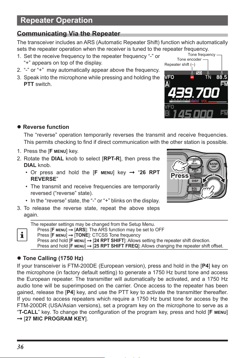
Repeater Operation
Tone frequency
Repeater shift
Communicating Via the Repeater
The transceiver includes an ARS (Automatic Repeater Shift) function which automatically
sets the repeater operation when the receiver is tuned to the repeater frequency.
1. Set the receive frequency to the repeater frequency “-” or
“+” appears on top of the display.
2. “-” or “+” may automatically appear above the frequency.
3. Speak into the microphone while pressing and holding the
PTT switch.
z Reverse function
The “reverse” operation temporarily reverses the transmit and receive frequencies.
This permits checking to find if direct communication with the other station is possible.
1. Press the [
F MENU
] key.
2. Rotate the DIAL knob to select [RPT-R], then press the
DIAL knob.
• Or press and hold the [
F MENU
] key “26 RPT
REVERSE”
• The transmit and receive frequencies are temporarily
reversed (“reverse” state).
• In the “reverse” state, the “-” or “+” blinks on the display.
3. To release the reverse state, repeat the above steps
again.
The repeater settings may be changed from the Setup Menu.
Press [F MENU] [ARS]: The ARS function may be set to OFF
Press [F MENU] [TONE]: CTCSS Tone frequency
Press and hold [F MENU] [24 RPT SHIFT]: Allows setting the repeater shift direction.
Press and hold [F MENU] [25 RPT SHIFT FREQ]: Allows changing the repeater shift offset.
Tone encoder
(–)
Press
z Tone Calling (1750 Hz)
If your transceiver is FTM-200DE (European version), press and hold in the [P4] key on
the microphone (in factory default setting) to generate a 1750 Hz burst tone and access
the European repeater. The transmitter will automatically be activated, and a 1750 Hz
audio tone will be superimposed on the carrier. Once access to the repeater has been
gained, release the [P4] key, and use the PTT key to activate the transmitter thereafter.
If you need to access repeaters which require a 1750 Hz burst tone for access by the
FTM-200DR (USA/Asian versions), set a program key on the microphone to serve as a
“T-CALL” key. To change the configuration of the program key, press and hold [F
[27 MIC PROGRAM KEY].
36
MENU
]
Page 39

Using the Memory
MEMORY CH LIST
The FTM-200DR/DE incorporates a large number of memory channels that can register
the operating frequency, communication mode, and other operational information.
• 999 Memory Channels
• 5 Home Channels
• 50 pairs PMS Memory Channels
m The memory auto grouping (MAG) function can automatically recall a list of memory
channels from the same frequency band as a group.
m The PMG-SR (Single Receiver Primary Memory Group Activity Monitor) function
displays the status of registered frequently used frequencies (received signal strength)
in a bar graph, and automatically selects and receives the channel with the signal.
The operating frequency and other operational information can be registered to each
regular memory channel, home channel, or PMS memory channel:
• Operating frequency • Communication Mode • Frequency Step
• Transmitter output • Memory tag • Repeater Shift
• TX/RX DG-ID • Tone information • DCS information
• Memory channel skip information
Back up the stored contents to a microSD memory card. See the Advanced Manual for details
on backing up to a microSD card.
NOTE
Writing to memory
1. Set the VFO frequency to write to memory.
2. Press and hold the [V/M
The memory channel list appears.
The lowest available channel number is selected. To
select another channel, rotate the DIAL knob to select the
memory channel number to be written.
The memory channel list can also be displayed by the
following operations:
Press the [F menu] key Select [KEYPAD]
Press the DIAL knob Select [MEMORY CH LIST]
Press the DIAL knob
The last used memory channel is selected.
• Press the [UP] or [DWN] key on the microphone to
select in 10 channel steps.
• Press the number keys on the microphone to quickly select
a memory channel as shown in the example below:
Press the [1] key: Memory channel 100
Press the [A] key: PMS Memory channel L01
• When [HOM] at the top of the memory channel list is
selected, the HOME channel of the current frequency
band can be overwritten.
For already written memory channels, the writing frequency
is displayed.
MW] key.
001 145.000
002
‐‐‐
003
‐‐‐
004
‐‐‐
.
.
.
‐‐‐‐‐
‐‐‐‐‐
‐‐‐‐‐
ーーーー
ーーーー
ーーーー
37
Page 40

3. Press and hold the [V/M MW] key.
ーーーー
ーーーー
ーーーー
MEMORY CH LIST
ーーーー
ーーーー
MEMORY CH LIST
Alternatively, press the DIAL knob to highlight [WRITE] and
a pop-up will be displayed. Press the DIAL knob again.
If you attempt to register a frequency to a memory channel
that already contains frequency data, “OVER WRITE?”
will appear on the screen. Rotate the DIAL knob to select
[OK], then press the DIAL knob to overwrite the memory
channel.
4. The memory is stored.
The written memory channel is recalled.
Recall memory (There are three ways)
(1) Press [V/M] key to recall
1. Press the [V/M MW] key.
The last used memory channel is recalled.
2. Rotate the DIAL knob to select the memory channel to
recall.
• Press and then rotate the DIAL knob to select in
10-channel steps.
• Press the [V/M
(2) Recall from the Function List
1. Press the [
2. Press the DIAL knob.
Or press and hold the [F MENU] key [1 FRERUENCY INPUT]
3. Rotate the DIAL knob to select [MEMORY CH LIST] then
press the DIAL knob.
The memory channel list appears.
F MENU
The memory channel list can also be displayed by the
following operations.
1. Press and hold [F
2. Press the DIAL knob.
MW] key again to return to VFO mode.
] key.
MENU]
[18 MEMORY LIST]
145.000
001
002
003
004
KEYPAD
SCAN
SQL
RPT-R
DTMF
‐‐‐.‐‐‐‐‐
‐‐‐.‐‐‐‐‐
‐‐‐.‐‐‐‐‐
Press
TXPWR HIGH
OFF
ARS
TONE 100.0
APRS OFF
HOME
AUTO
3. Rotate the DIAL knob to select [MEMORY CH] then press
the DIAL knob to display the memory channel list.
• Press the [UP] or [DWN] key on the microphone to
select in 10 channel steps.
• Press the number keys on the microphone to quickly select
a memory channel as shown in the example below:
Press the [1] key: Memory channel 100
Press the [A] key: PMS Memory channel L01
4. Rotate the DIAL knob, select the memory channel to
recall, then press the DIAL knob.
5. A pop-up with [RECALL] highlighted appears. Press the
DIAL knob.
The selected memory channel will be recalled.
38
001 145.000
002
433.300
003
004
.
‐‐‐
.
‐‐‐
‐‐‐‐‐
‐‐‐‐‐
Page 41

(3) Recalling a memory by directly entering the channel number
z Recalling a memory on the keypad screen
1. Press the [F
2. Press the DIAL knob.
Or press and hold the [F MENU] key [1 FRERUENCY INPUT]
3. Rotate the DIAL knob to select a memory channel
number, then press the DIAL knob.
(Example) When recalling memory channel “123”.
Rotate the DIAL knob to select [1] Press the DIAL knob
Rotate the DIAL knob to select [2] Press the DIAL knob
Rotate the DIAL knob to select [3] Press the DIAL knob
(Example) When recalling memory channel “16”.
Rotate the DIAL knob to select [1] Press the DIAL knob
Rotate the DIAL knob to select [6] Press the DIAL knob
Press and hold the DIAL knob
MENU
] key in the memory mode.
KEYPAD
SCAN
SQL
RPT-R
DTMF
OFF
HOME
TXPWR HIGH
ARS
AUTO
TONE 100.0
APRS OFF
z Recall a memory by directly inputting channels using the numeric keys on the microphone
Press the numeric keys “0” to “9” in the memory mode to
enter the memory channel.
(Example) When recalling memory channel “123”.
Press the [1] key.
Press the [2] key.
Press the [3] key.
(Example) When recalling memory channel “16”.
Press the [1] key.
Press the [6] key.
Press and hold any numeric key.
Press the PTT switch while entering a number to cancel the entry.
z Copy memory channel information to VFO
1. Press and hold the [BAND GRP] key while recalling
memory.
Copy the contents of the recalled memory channel to the
VFO and enter VFO mode.
39
Page 42
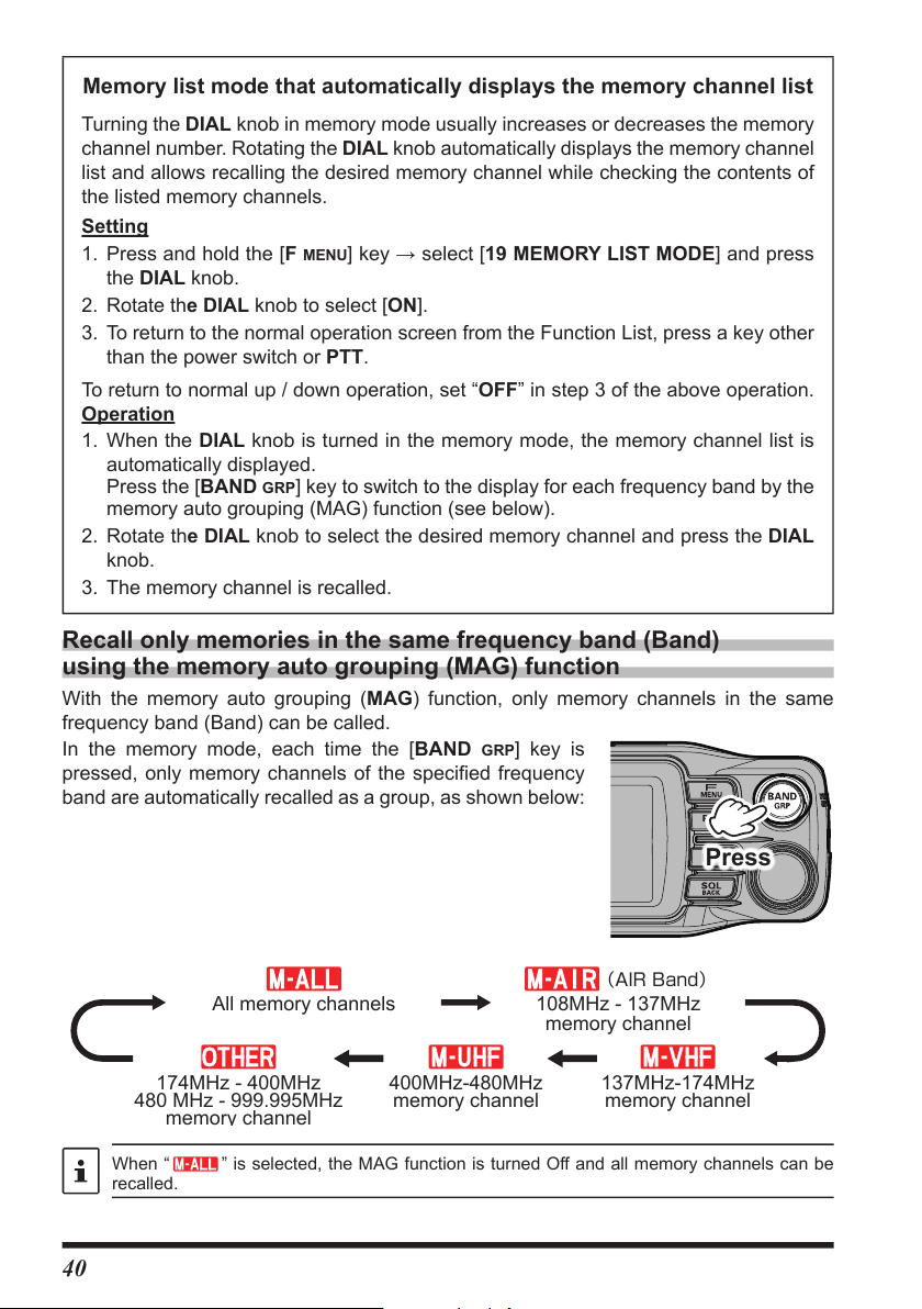
Memory list mode that automatically displays the memory channel list
(AIRBand)
memory channel
Turning the DIAL knob in memory mode usually increases or decreases the memory
channel number. Rotating the DIAL knob automatically displays the memory channel
list and allows recalling the desired memory channel while checking the contents of
the listed memory channels.
Setting
1. Press and hold the [F
the DIAL knob.
2. Rotate the DIAL knob to select [ON].
3. To return to the normal operation screen from the Function List, press a key other
than the power switch or PTT.
To return to normal up / down operation, set “OFF” in step 3 of the above operation.
Operation
1. When the DIAL knob is turned in the memory mode, the memory channel list is
automatically displayed.
Press the [BAND
memory auto grouping (MAG) function (see below).
2. Rotate the DIAL knob to select the desired memory channel and press the DIAL
knob.
3. The memory channel is recalled.
MENU
] key → select [19 MEMORY LIST MODE] and press
GRP] key to switch to the display for each frequency band by the
Recall only memories in the same frequency band (Band) using the memory auto grouping (MAG) function
With the memory auto grouping (MAG) function, only memory channels in the same
frequency band (Band) can be called.
In the memory mode, each time the [BAND
pressed, only memory channels of the specified frequency
band are automatically recalled as a group, as shown below:
GRP] key is
Press
All memory channels
174MHz - 400MHz
480 MHz - 999.995MHz
When “ ” is selected, the MAG function is turned Off and all memory channels can be
recalled.
400MHz-480MHz
memory channel
108MHz - 137MHz
memory channel
137MHz-174MHz
memory channel
40
Page 43

Group Selectable Memory Channels
MEMORY CH LIST
MEMORY CH LIST
MEMORY INFORMATION
All memory channels.
(Blinking)
(Blinking)
(Blinking)
(Blinking)
AIR band (108 - 137MHz) memory channels only.
144MHz band (137 - 174MHz) memory channels only.
430MHz band (400 - 480MHz) memory channels only.
174MHz to 400MHz and 480MHz to 999.995MHz Memory channels
Edit memory
z Edit memory tag
Memory name tags, such as a call sign or broadcast station name may be assigned to
the memory channels and home channels. Input a memory tag using up to 16 characters.
Alphabetic characters (upper and lowercase), Numbers and Symbols may be entered to
the memory name tag.
1. Press and hold the [V/M
The memory channel list appears. The lowest available
number is selected.
The memory channel list can also be displayed by the
following operations:
Press the [F menu] key Select [KEYPAD]
Press the DIAL knob Select [MEMORY CH LIST]
Press the DIAL knob
The last used memory channel is selected.
2. Rotate the DIAL knob to select the memory channel to
edit the memory tag, then press the DIAL knob.
3. A popup will appear. Rotate the DIAL knob to select
[EDIT] then press the DIAL knob.
The memory information appears.
4. Rotate the DIAL knob to select [TA G ], then press the
DIAL knob.
• The character input screen is displayed. Rotate the
DIAL knob to select a character, and press the DIAL
knob to enter the character.
: moves the cursor to the left.
: moves the cursor to the right.
: displays the alphabet keypad input screen.
: displays the numeric keypad input screen.
: displays the symbols keypad input screen.
: erases the character to the left of the cursor and
moves the cursor to the left.
• See “Text input screen” on page 76 to input a
memory tag.
MW] key.
021 433.300 YAESU
022
433.620 FTM-200D
433.300 JA1YOE
033
433.100
041 DIGITAL
433.200
021 433.300 YAESU
022
433.620 FTM-200D
433.300 JA1YOE
033
433.100
041 DIGITAL
433.200
RX FREQ
TX FREQ
TAG
SCAN
OK BACK
433.340
|||
|||
.
YES
>
41
Page 44

5. When input is complete, press and hold the DIAL knob to save the characters and
MEMORY CH LIST
100.0
return to “MEMORY INFORMATION” screen.
6. Rotate the DIAL knob to select [OK], then press the DIAL knob.
7. A confirmation pop-up appears. Select [OK] then press the DIAL knob to complete the
memory tag entry.
The Memory tag is only displayed on the operating band.
z Clearing Memories
1. Press and hold the [V/M MW] key.
The memory channel list appears. The lowest available
number is selected.
The memory channel list can also be displayed by the
following operations:
Press the [F menu] key Select [KEYPAD]
Press the DIAL knob Select [MEMORY CH LIST]
Press the DIAL knob
The last used memory channel is selected.
2. Rotate the DIAL knob to select the memory channel from
which the data is to be cleared, and press the DIAL knob.
3. A pop-up appears. Rotate the DIAL knob to select
[DELETE] then press the DIAL knob.
Confirmation screen “DELETE?” is displayed.
4. Rotate the DIAL knob to select [OK], then press the DIAL
knob.
021 433.300 YAESU
022
433.620 FTM-200D
433.300 JA1YOE
033
433.100
041 DIGITAL
433.200
Memory channel 001 and home channel cannot be deleted.
Recalling the Home Channels
z Recall from the Function List
F MENU
1. Press the [
2. Rotate the DIAL knob, select [HOME], then press the
DIAL knob.
• Or press and hold the [
• “HOME” and the home channel frequency of the
currently selected band appears on the LCD.
] key.
F MENU
] key → “17 HOME”
z Recall with the programmable key on the microphone
1. Press the [P2]* key on the microphone.
* This is the factory setting. This function can also be
assigned to the [P3] or [P4] key (see page 17).
“HOME” and the home channel frequency of the currently
selected band appears on the LCD.
2. Press the [P2] key again, to return to the previous
frequency.
While recalling the home channel, rotate the DIAL knob to
transfer the home channel frequency to the operating band VFO.
42
KEYPAD
SCAN
SQL
RPT-R
DTMF
OFF
HOME
TXPWR HIGH
AUTO
ARS
TONE
APRS OFF
Page 45

Changing the Home Channel Frequency
MEMORY CH LIST
MEMORY INFORMATION
1. Set the frequency and the operating mode to be stored as
a home channel.
F MENU
2. Press the [
] key.
3. Rotate the DIAL knob, select [HOME], then press and
hold the DIAL knob.
“OVER WRITE HOME” will appear on the screen.
4. Rotate the DIAL knob to select [OK], then press the DIAL
knob to overwrite the memory channel.
Select [HOM] in the writing procedure of the memory channel
list to overwrite and save to the home channel.
See “Writing to Memory” on page 37.
KEYPAD
SCAN
SQL
RPT-R
DTMF
OFF
to HOME
HOME
TXPWR HIGH
AUTO
ARS
TONE 100.0
APRS OFF
Split Memory
Two different frequencies, one for receive and another for transmit, can be registered to
a memory channel.
1. Register the receive frequency to a memory channel first.
For additional details on registering to a memory channel,
refer to “Writing to memory” (page 37).
To edit a memory channel that has already been written,
go to step 2.
2. Press and hold the [V/M
MW] key.
The memory channel list appears.
The memory channel list can also be displayed by the following operations:
Press the [F menu] key Select [KEYPAD] Press the DIAL knob
Select [MEMORY CH LIST] Press the DIAL knob
The last used memory channel is selected.
YAESU MUSEN
3. Rotate the DIAL knob to select the channel number that the receive frequency was
registered to on step1, and press the DIAL knob.
4. Rotate the DIAL knob to select [EDIT], then press the
DIAL knob.
021 433.300 YAESU
022
433.620 FTM-200D
433.300 JA1YOE
033
433.100
041 DIGITAL
433.200
5. Rotate the DIAL knob to select [TX FREQ], then press
the DIAL knob.
RX FREQ
TX FREQ
TAG
YAESU
SCAN
OK BACK
433.340
|||
|||
.
YES
43
>
Page 46

6. Rotate the DIAL knob to select a number, and press the
DIAL knob to enter.
7. Rotate the DIAL knob to select [OK], then press the DIAL
knob.
8. Confirmation screen is displayed, press the DIAL knob.
• The edited memory channel is recalled.
• When recalling split memory, the “
” icon appears on
the display.
YAESU MUSEN
• On the memory channel list screen, the receive
frequency is displayed on the upper area and the
transmit frequency is displayed on the lower part of the
split memory channel.
While operating the split memory, to reverse the transmit and receive frequencies temporarily:
Press [F MENU] → Select [RPT-R]
When reversing the frequencies, “ ” will blink.
MEMORY CH LIST
021 433.300 YAESU
022
433.620 FTM-200D
433.300 JA1YOE
033
433.100
041 DIGITAL
433.200
44
Page 47

PMG-SR (Single Receiver Primary Memory Group)
Activity Monitor
By pressing and holding the [PMG pw] key, the current VFO or Memory Channel display
frequency can be registered in the PMG group. Simply press the [PMG pw] key to call
up the PMG screen and display the reception status of the registered channels in a bar
graph.
Auto mode scans and stops at the channel with a signal to play the received audio. The
scan resumes when there is no signal. When you press the PTT or DIAL knob to switch
to manual mode, and turn the DIAL knob to fix receive to the selected channel, and
play the received audio when there is a signal. When there is no signal on the selected
channel, scan resume and displays the reception status of the other channels in real time.
However, the received audio is not played even if there is a signal on the other channel.
(On the PMG-SR screen, the real-time reception status of other channels is not displayed
while the received audio of the manually selected channel is playing.)
PMG channel number
PMG icon
: AUTO Mode
: MANUAL Mode
Currently selected channel
(displayed in orange)
YAESU MUSEN
Example: When 3 frequencies are registered
Register the frequency to PMG
currently selected
Memory channel tag
PMG channel number
(The selected channel is
displayed in orange)
1. Set the frequency of the VFO or Memory Channel regis-
tered in the PMG.
2. Press and hold the [PMG pw] key to register the current
frequency in PMG and immediately display the PMG
activity monitor screen.
3. To continue registering additional frequencies, press the
[PMG
PW] key to return to the original screen, and then
repeat steps 1 and 2 above.
Call up the PMG screen
1. Press the [PMG PW] key to display the PMG screen.
Press again to return to the original screen.
YAESU MUSEN
45
Page 48

Switch between Auto Mode and Manual Mode
Since the PMG 3CH signal has disappeared,
scanning is automatically resumed.
Receives signal with PMG 1CH and
selects automatically
1. On the PMG screen, press the DIAL knob to switch each
time between Auto Mode and Manual Mode.
: Auto Mode
: Manual Mode
Auto Mode
• Scans channels registered in PMG continuously at
high speed. (The PMG channel number flashes during
scanning and there is no sound from the speaker.)
• Automatically stops at the channel with a signal and
outputs the received audio. When a channel is active,
the bar graphs of other channels pause and display the
last reception state.
• When there is no signal, scanning will resume after
about 1 second.
• When operating on the received channel, press the
PTT or DIAL knob to switch to manual mode, which is
fixed to the selected channel for communication.
YAESU MUSEN
Operation example
in Auto Mode
YAESU MUSEN
YAESU MUSEN
Operation of Auto Mode
• Each time the DIAL knob is pressed, the Auto Mode and Manual Mode are toggled.
• Rotate the DIAL knob to change the channel while keeping the auto mode. If there is no
signal on the selected channel, scanning will resume automatically after about 1 second.
46
Page 49

Manual Mode
Since there is no signal on the selected
PMG 2CH, the bar graph is displayed
continuously.
Since the signal was received by the
selected PMG 2CH, the bar graph
display is paused and the received
sound is output.
• The channel is fixed, and you can turn the DIAL knob
to select the desired channel and communicate.
• If there is no signal on the selected channel, scanning
continuously displays the reception status (signal
strength) of other channels in a bar graph. (Received
audio is not output even if there is a signal on another
channel.)
Operation example
in Manual Mode
YAESU MUSEN
• If there is a signal on the selected channel, the received
audio is output. During audio output, the bar graphs of
the other channels hold their last state and pause.
• When the signal on the selected channel concludes,
scan is automatically restarted and the bar graph is
displayed continuously.
Operation of Manual Mode
• In manual mode, the channel is fixed. Rotate the DIAL knob to select the desired
channel.
• Press PTT to communicate with other stations on the selected PMG channel.
• Each time the DIAL knob is pressed, the auto mode and manual mode are toggled.
Unregister the channel (frequency) registered in PMG
Up to 5 channels can be registered in PMG. To register a new frequency, cancel the
registration of one frequency and then register the new frequency.
1. Select the channel (frequency) to be unregistered by touching the bar graph or rotating
the DIAL knob.
] key to cancel the registration.
2. Press and hold the [PMG
• Channels after the canceled channel have the previous number.
• When all registered channels are lost, PMG will be canceled and the screen will
return to the original screen.
Cancel all frequency (channels) registered in PMG.
1. Press and hold the [F menu] key
2. Press the DIAL knob.
PW
→ [20 PMG CLEAR]
YAESU MUSEN
47
Page 50

Scanning Function
Press and hold
The FTM-200DR/DE supports the following three scanning functions:
• VFO Scan
• Memory Scan
• Programmable Memory Scan (PMS)
VFO Scan / Memory Scan
To find frequencies where there are signals in VFO mode or Memory mode:
1. Press the [A/B] key to set the band to be scanned as the
operation band.
2. Press the [V/M mw] key to select the "VFO mode" or
"Memory mode".
3. Press the [F menu] key →“SCAN”→ Press the DIAL knob.
Or press and hold the microphone [UP] or [DWN] switch
to start scanning.
• If the DIAL knob is rotated while scanning is in progress,
the scanning will continue up or down in frequency
according to the direction of the DIAL Knob rotation.
• When a signal is received, the scan pauses, the
frequency flashes, and the scan starts again after
about 3 seconds. In the USA version, the scan will
continue to pause while receiving the signal.
z Stop scanning
1. Press the [F menu] key → “SCAN” → press the DIAL knob.
Or press PTT or the [UP] / [DWN] keys on microphone.
KEYPAD
SCAN
SQL
RPT-R
DTMF
OFF
HOME
TXPWR HIGH
ARS
AUTO
TONE 100.0
APRS OFF
• If the scan has paused on a signal, rotating the DIAL knob will cause scanning to resume instantly.
• If the transcei
will resume.
• If you call the Function List or Setup Menu during scanning, the SCAN item is automatically
selected and you cannot select any other item.
ver is turned OFF while scanning, when the transceiver is turned ON, scanning
Setting the Receive Operation When Scanning Stops
1. Press and hold the [F menu] key.
2. Rotate the DIAL knob to select [53 SCAN RESUME],
then press the DIAL knob.
3. Rotate the DIAL knob to select the hold time after the
scan is paused:
• BUSY
The signal is received until the signal fades out. Two
seconds after the signal fades out, scanning resumes.
• HOLD
Scanning stops and tuning remains on the current receive frequency (Scanning
does not resume).
• 1 sec / 3 sec / 5 sec
The signal is received for a specified period of time, and then scanning resumes.
Factory default setting: BUSY (USA Version)
3 sec (except USA Version)
48
Page 51

4. To return to the normal operation screen, press a key other than the power switch or PTT.
The above settings are common for VFO scan, memory scan and programmable memory scan
(PMS).
Skip Memory Channels
Each memory channel can be set to be skipped during memory scan.
1. Press and hold the [V/M mw] key.
The memory channel list appears.
The memory channel list can also be displayed by the following operations:
Press the [F menu] key Select [KEYPAD]
Press the DIAL knob Select [MEMORY CH LIST]
Press the DIAL knob
The last used memory channel is selected.
2. Rotate the DIAL knob to select the memory channel number that you do not want to
scan, and press the DIAL knob.
3. Rotate the DIAL knob to select [EDIT], then press the DIAL knob.
4. Rotate the DIAL knob to select [SCAN].
5. Press the DIAL knob to select [NO].
6. Rotate the DIAL knob to select [OK], then press the DIAL knob.
7. When the confirmation screen is displayed, press the DIAL knob.
When the memory channel set as the skip memory is called, the “
To cancel the skip memory, set it to “YES” in step 5 above.
” icon is displayed.
Programmable Memory scan (PMS)
This function scans only the range of frequencies between the lower and upper limits
registered in a pair of PMS Programmable Memory channels. 50 sets of PMS memory
channels (L01/U01 to L50/U50) are available.
For additional details on the Programmable Memory Scan (PMS) and Memory Bank Scan, refer to
the Advanced Manual which may be downloaded from the Yaesu website.
49
Page 52
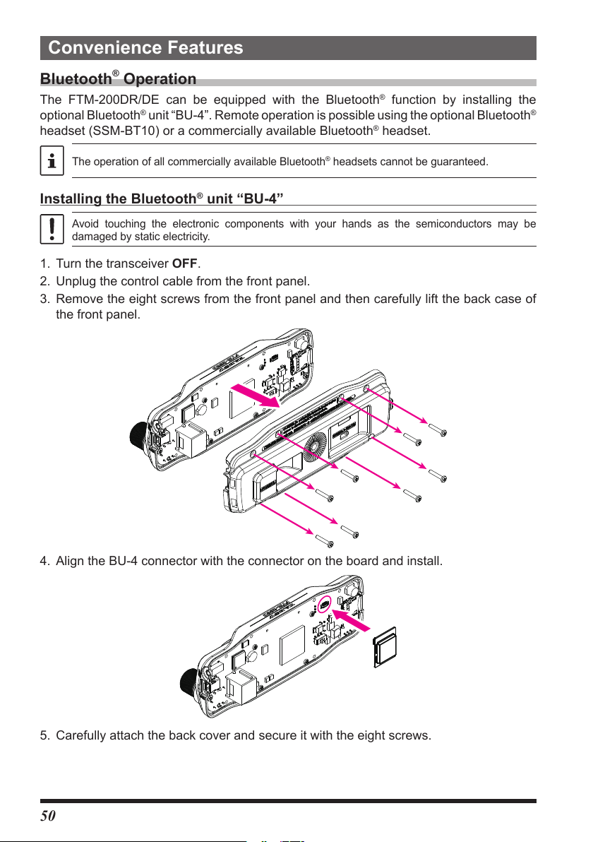
Convenience Features
Bluetooth® Operation
The FTM-200DR/DE can be equipped with the Bluetooth® function by installing the
optional Bluetooth
headset (SSM-BT10) or a commercially available Bluetooth
The operation of all commercially available Bluetooth® headsets cannot be guaranteed.
Installing the Bluetooth® unit “BU-4”
Avoid touching the electronic components with your hands as the semiconductors may be
damaged by static electricity.
1. Turn the transceiver OFF.
2. Unplug the control cable from the front panel.
3. Remove the eight screws from the front panel and then carefully lift the back case of
the front panel.
®
unit “BU-4”. Remote operation is possible using the optional Bluetooth®
®
headset.
4. Align the BU-4 connector with the connector on the board and install.
5. Carefully attach the back cover and secure it with the eight screws.
50
Page 53

Pairing the Bluetooth® Headset
Press and hold the Multi Function
Button for 3 seconds to turn ON.
Press and hold
When using the Bluetooth® Headset for the first time, the Bluetooth® Headset and the
FTM-200DR/DE must be paired.
This step is only necessary when first connecting the headset.
1. Press and hold the Multi-Function Button, until the
SSM-BT10 LED blinks red/blue alternately.
Blinks red
and blue
2. Press and hold the [F menu] key.
Power ON
3. Rotate the DIAL knob to select [107 Bluetooth] then
press the DIAL knob.
4. Press the DIAL knob and set [Bluetooth] to “ON”.
The setting items are displayed.
5. Press the DIAL knob.
6. Rotate the DIAL knob to select [DEVICE], then press the
DIAL knob.
7. Press the DIAL knob.
The search starts, and the model name of the found
Bluetooth
8. When the headset to be connected is displayed, press the
[SQL back] key to stop searching.
9. Rotate the DIAL knob to select the Bluetooth® headset to
be connected.
10. Press the [F menu] key, then press the DIAL knob.
®
device is displayed in the list.
OPTION
Bluetooth >
107
VOICE MEMORY >108
109
FVS REC
110
TRACK SELECT
>
OPTION
107 Bluetooth
DEVICE
ConnectedSTATUS
DisconnectedSTATUS
DEVICE LIST
SSM-BT10
yaesu-01
yaesu-02
Searching
DEVICE LIST
SSM-BT10
yaesu-01
yaesu-02
ONBluetooth
OFFSAVE
51
Page 54
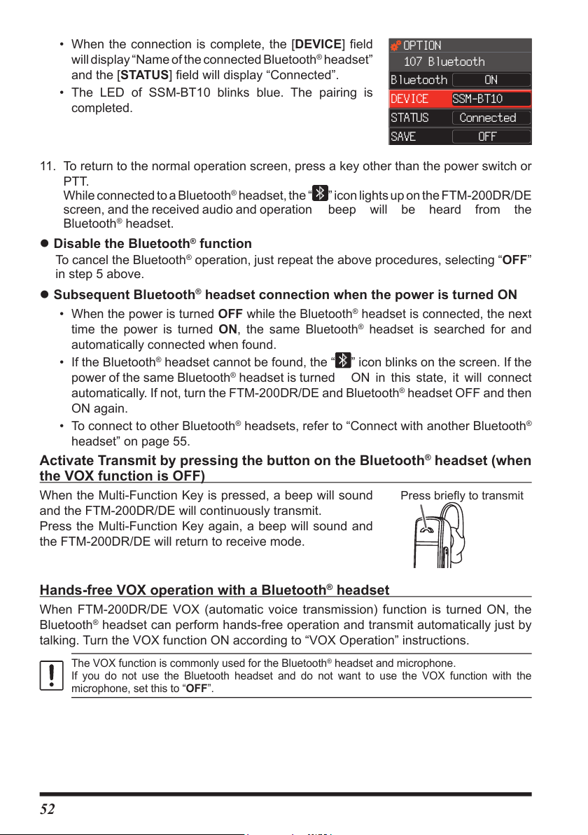
• When the connection is complete, the [DEVICE] field
Press briefly to transmit
will display “Name of the connected Bluetooth
®
headset”
and the [STATUS] field will display “Connected”.
• The LED of SSM-BT10 blinks blue. The pairing is
completed.
OPTION
107 Bluetooth
SSM-BT10DEVICE
ConnectedSTATUS
ConnectedSTATUS
ONBluetooth
OFFSAVE
11. To return to the normal operation screen, press a key other than the power switch or
PTT.
While connected to a Bluetooth
screen, and the received audio and operation beep will be heard from the
Bluetooth
®
headset.
®
headset, the “
” icon lights up on the FTM-200DR/DE
z Disable the Bluetooth® function
To cancel the Bluetooth® operation, just repeat the above procedures, selecting “OFF”
in step 5 above.
z Subsequent Bluetooth® headset connection when the power is turned ON
• When the power is turned OFF while the Bluetooth® headset is connected, the next
time the power is turned ON, the same Bluetooth
®
headset is searched for and
automatically connected when found.
• If the Bluetooth® headset cannot be found, the “ ” icon blinks on the screen. If the
power of the same Bluetooth
automatically. If not, turn the FTM-200DR/DE and Bluetooth
®
headset is turned ON in this state, it will connect
®
headset OFF and then
ON again.
®
• To connect to other Bluetooth
headsets, refer to “Connect with another Bluetooth
headset” on page 55.
Activate Transmit by pressing the button on the Bluetooth® headset (when the VOX function is OFF)
When the Multi-Function Key is pressed, a beep will sound
and the FTM-200DR/DE will continuously transmit.
Press the Multi-Function Key again, a beep will sound and
the FTM-200DR/DE will return to receive mode.
®
Hands-free VOX operation with a Bluetooth® headset
When FTM-200DR/DE VOX (automatic voice transmission) function is turned ON, the
Bluetooth
talking. Turn the VOX function ON according to “VOX Operation” instructions.
®
headset can perform hands-free operation and transmit automatically just by
The VOX function is commonly used for the Bluetooth® headset and microphone.
If you do not use the Bluetooth headset and do not want to use the VOX function with the
microphone, set this to “OFF”.
52
Page 55
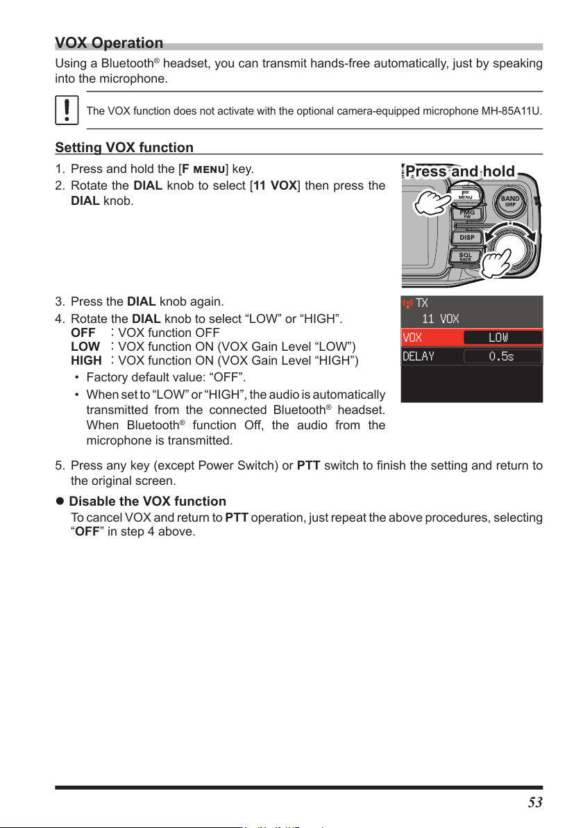
VOX Operation
Press and hold
Using a Bluetooth® headset, you can transmit hands-free automatically, just by speaking
into the microphone.
The VOX function does not activate with the optional camera-equipped microphone MH-85A11U.
Setting VOX function
1. Press and hold the [F menu] key.
2. Rotate the DIAL knob to select [11 VOX] then press the
DIAL knob.
3. Press the DIAL knob again.
4. Rotate the DIAL knob to select “LOW” or “HIGH”.
OFF : VOX function OFF
LOW : VOX function ON (VOX Gain Level “LOW”)
HIGH : VOX function ON (VOX Gain Level “HIGH”)
TX
11 VOX
LOWVOX
0.5sDELAY
• Factory default value: “OFF”.
• When set to “LOW” or “HIGH”, the audio is automatically
transmitted from the connected Bluetooth
When Bluetooth
®
function Off, the audio from the
®
headset.
microphone is transmitted.
5. Press any key (except Power Switch) or PTT switch to finish the setting and return to
the original screen.
z Disable the VOX function
To cancel VOX and return to PTT operation, just repeat the above procedures, selecting
“OFF” in step 4 above.
53
Page 56

Set the VOX (Voice Operated Transmit) delay time
Press and hold
Press and hold
OPTION
During transmissions using the VOX (Voice Operated Transmit) function, set the time to
return to receive when speaking is paused:
1. Press and hold the [F menu] key.
2. Rotate the DIAL knob to select [11 VOX], then press the
DIAL knob.
3. Rotate the DIAL knob to select [DELAY] then press the
DIAL knob.
4. Rotate the DIAL knob to select the delay time (the transmit-
receive delay after the cessation of speech).
0.5s / 1.0s / 1.5s / 2.0s / 2.5s / 3.0s
Factory default value: “0.5s”.
5. Press the [DISP] key to complete the setting.
AUDIO
11 VOX
LOWVOX
0.5sDELAY
Bluetooth® battery save function
Turning ON the Bluetooth® Battery Saver feature extends the standby battery life of the
Bluetooth
1. Press and hold the [F menu] key.
2. Rotate the DIAL knob to select [Bluetooth], then press
®
headset.
the DIAL knob.
3. Rotate the DIAL knob to select [SAVE], then press the
DIAL knob to select “ON”.
4. Press any key (except Power Switch) or PTT switch to
finish the setting and return to the original screen.
z Disable the battery save function
To cancel Bluetooth® Battery Saver feature, just repeat the above procedures, selecting
“OFF” in step 3 above.
54
107 Bluetooth
ONBluetooth
SSM-BT10SAVE
ConnectedSTATUS
ONSAVE
Page 57

Connect with another Bluetooth® headset
Press and hold
DEVICE LIST
1. Press and hold the [F menu] key.
2. Rotate the DIAL knob to select [107 Bluetooth], then
press the DIAL knob.
3. If the “STATUS” field shows “Connected”, rotate the DIAL
knob to select [STATUS] then press the DIAL knob.
“Disconnected” is displayed in the “STATUS” field.
4. Rotate the DIAL knob to select [DEVICE], then press the
DIAL knob.
5. Press the [F menu] key.
6. Rotate the DIAL knob to select [SEARCH], then press the
DIAL knob.
®
• Search Bluetooth
devices to display them in the
device list in the following order:
(1) Already registered, searched and found Bluetooth
devices: white letters
(2) Searched and found new
Bluetooth
(3) Already registered but not found by search
Bluetooth
®
devices: white letters
®
devices: gray letters
• To interrupt the search, press the [SQL back] key.
7. When the headset to be connected is displayed, press the
[SQL back] key to stop searching.
8. Rotate the DIAL knob to select the desired Bluetooth
device.
9. Press the [F menu] key.
10. Rotate the DIAL knob to select [CONNECT], then press
the DIAL knob to connect.
®
®
SSM-BT10
SSM-BT10
yaesu-01
yaesu-02
R556
SSM-BT10
yaesu-01
yaesu-02
R556
OPTION
107 Bluetooth
SSM-BT10DEVICE
ConnectedSTATUS
DisconnectedSTATUS
DEVICE LIST
DEVICE LIST
Searching
ONBluetooth
OFFSAVE
z Connecting to a registered (paired) Bluetooth® headset
1. Perform step 4 above to display the device list.
2. Rotate the DIAL knob to select a Bluetooth
3. Press the [F menu] key, then press the DIAL knob.
4. When the connection is completed, “Connected” is displayed in the STATUS” field.
®
headset to connect to.
55
Page 58

z Remove a registered (paired) Bluetooth® device from the list
Press and hold
1. In step 2 above, rotate the DIAL knob to select the Bluetooth® headset to be deleted.
2. Press the [F menu] key.
3. Rotate the DIAL knob to select [DEL], then press the DIAL knob.
4. The Bluetooth
®
headset is deleted from the device list.
Bluetooth® received audio output
When a Bluetooth® headset is connected, the received audio can automatically be output
from the headset only, or from both the headset and the transceiver speaker.
1. Press and hold the [F menu] key.
2. Rotate the DIAL knob to select [Bluetooth], then press
the DIAL knob.
3. Rotate the DIAL knob to select [AUDIO], then press the
DIAL knob.
4. Rotate the DIAL knob to select “AUTO” or “FIX”.
AUTO :
FIX :
Factory default value: “AUTO”.
5. Press any key (except Power Switch) or PTT switch to
finish the setting and return to the original screen.
The received audio comes from only the
Bluetooth headset.
The received audio comes from both the
Bluetooth headset and the speaker of this
transceiver.
OPTION
107 Bluetooth
DEVICE
ConnectedSTATUS
DisconnectedSTATUS
OFFSAVE
AUTOAUDIO
56
Page 59

Band Scope
The Band Scope displays the current VFO frequency or Memory Chanel at the center of
of a Bar graph with the signal status of a number of frequencies or channels displayed to
the left and right at the bottom of the screen. The center frequency or memory channel
can be changed by turning the DIAL knob.
When there is a signal on the center channel, the bar graph display of other frequencies
is paused and you can hear the received audio. When there is no signal, the bar graph
display is automatically resumed.
1. Press the [DISP] key to display the band scope.
VFO mode:
The status (strengths) of the signals in the upper and
lower frequency channels (61CH or 31CH) centered on
the current receive frequency are displayed in the bar
graph.
The Band Scope frequency step is the same as the VFO
frequency step.
Memory mode:
• The status (strengths) of the signals in the upper and
lower memory channels (21CH or 11CH) centered on
the current memory channel are displayed in the graph.
• Memory channels that have not been registered are
not displayed.
• The bar graph for the central memory channel is
displayed in orange.
z Change frequency or Memory Channels
Rotate the DIAL knob to change the receive frequency or
memory channel at the center of the band scope.
z Exit the Band Scope
Press the [DISP] key.
Display example
VFO Mode (61CH)
Display example
MEMORY Mode (21CH)
z Change the number of channels displayed
1. Press and hold the [F menu] key.
2. Rotate the DIAL knob to select [SCOPE], then press the DIAL knob.
3. Rotate the DIAL knob to select “WIDE” or “NARROW”.
The number of channels displayed in each mode is as follows:
WIDE NARROW
VFO mode 61 channels 31 channels
Memory mode 21 channels 11 channels
Factory default value: “WIDE”.
4. Press any key (except Power Switch) or PTT switch to conclude the the setting and
return to the original screen.
57
Page 60
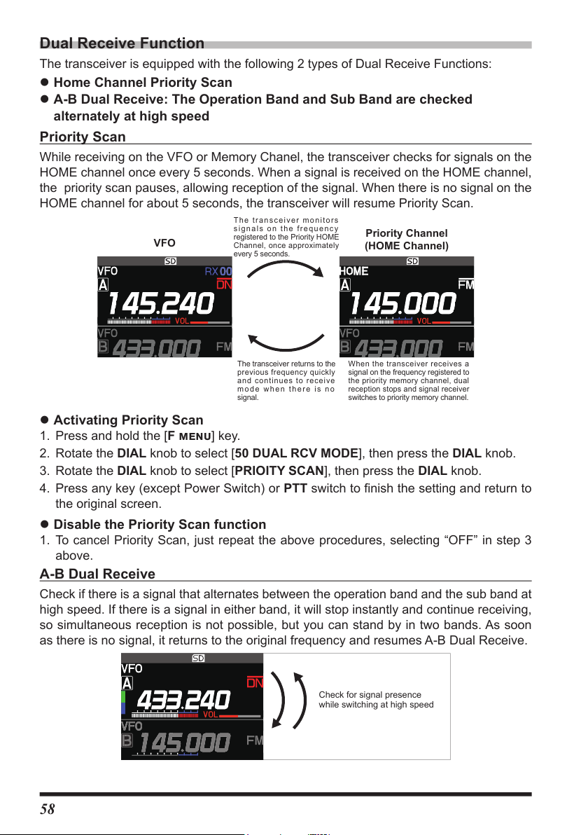
Dual Receive Function
The transceiver monitors
The transceiver is equipped with the following 2 types of Dual Receive Functions:
z Home Channel Priority Scan
z A-B Dual Receive: The Operation Band and Sub Band are checked
alternately at high speed
Priority Scan
While receiving on the VFO or Memory Chanel, the transceiver checks for signals on the
HOME channel once every 5 seconds. When a signal is received on the HOME channel,
the priority scan pauses, allowing reception of the signal. When there is no signal on the
HOME channel for about 5 seconds, the transceiver will resume Priority Scan.
VFO
signals on the frequency
registered to the Priority HOME
Channel, once approximately
every 5 seconds.
Priority Channel
(HOME Channel)
The transceiver returns to the
previous frequency quickly
and continues to receive
mode when there is no
signal.
When the transceiver receives a
signal on the frequency registered to
the priority memory channel, dual
reception stops and signal receiver
switches to priority memory channel.
z Activating Priority Scan
1. Press and hold the [F menu] key.
2. Rotate the DIAL knob to select [50 DUAL RCV MODE], then press the DIAL knob.
3. Rotate the DIAL knob to select [PRIOITY SCAN], then press the DIAL knob.
4. Press any key (except Power Switch) or PTT switch to finish the setting and return to
the original screen.
z Disable the Priority Scan function
1. To cancel Priority Scan, just repeat the above procedures, selecting “OFF” in step 3
above.
A-B Dual Receive
Check if there is a signal that alternates between the operation band and the sub band at
high speed. If there is a signal in either band, it will stop instantly and continue receiving,
so simultaneous reception is not possible, but you can stand by in two bands. As soon
as there is no signal, it returns to the original frequency and resumes A-B Dual Receive.
Check for signal presence
while switching at high speed
58
Page 61

z Activating the A-B Dual Receive
Press and hold
1. Press and hold the [F menu] key.
2. Rotate the DIAL knob to select [50 DUAL RCV MODE], then press the DIAL knob.
3. Rotate the DIAL knob to select [A-B DUAL RECEIVE], then press the DIAL knob.
4. Press any key (except Power Switch) or PTT switch to finish the setting and return to
the original screen.
z Disable the A-B Dual Receive
1. To cancel A-B Dual Receive, just repeat the above procedures, selecting “OFF” in step
3 above.
Using the Voice Recorder
The voice recording function automatically starts recording when a signal is received, and
pauses when there is no signal. Can be record the received audio of the other station or
the transmitted audio of the FTM-200DR/DE to a microSD memory card for a long time.
The recorded file can be played back with the FTM-200DR/DE or the MicroSD memory
card can be taken out and used on a PC.
Once recording is started, it continues until recording is stopped, or the capacity of the
microSD card is full.
z About the file
• The audio file is saved in the “VOICE” folder on the MicroSD card.
• The file is a Wave sound format (extension: wav).
• The file name is “YYYYMMDDmmhhss.wav” (YYYY: year, MM: month, DD: day, hh: hour,
mm: minute, ss: second) depending on the date and time when the recording started.
• When using the MicroSD memory card for the first time, please refer to “Formatting a MicroSD
Memory Card” on page 27
• Since the date and time are used for the file name and time stamp, it is recommended to
receive GPS or set the date and time in advance when using the voice recording function.
Press and hold the [F menu] key → [28 DATE&TIME ADJUST] (page 68)
Recording the receive audio
1. Press and hold the [F menu] key.
2. Rotate the DIAL knob to select [39 REC/STOP], then
press the DIAL knob.
“REC” is displayed, and the recording function starts.
3. Press any key (except Power Switch) or PTT to finish the
complete the setting and return to the original screen.
• “
enters the recording standby mode.
• When a signal is received, recording starts
automatically. During recording, the “
changes to “
• Recording will be paused about 3 seconds after
the squelch of the band that is recording is closed.
Recording will resume when a signal is received.
• With the factory default settings, the “A-band” received
audio is recorded.
” is displayed at the top of the LCD, the transceiver
” indication
”.
59
Page 62

• The band or bands to be recorded, and whether or not
Press and hold
to include the transmit audio in the recording may be
selected in the Setup Menu.
Turning Off the power of the radio stops the recording function.
z Disable the recording function
1. Press and hold the [F menu] key.
2. Rotate the DIAL knob to select [39 REC/STOP], then
press the DIAL knob.
• “
STOP” is displayed and the recording function is
stopped.
• When a new recording is started, a new file will be
created.
Setting the Recording function
The band or bands to be recorded, and whether or not to include the transmit audio in the
recording may be selected. It cannot be changed during recording, so set them before
stopping recording.
1. Press and hold the [F menu] key.
2. Rotate the DIAL knob to select [38 RECORDING], then
press the DIAL knob.
3. Press the DIAL knob again.
4. Rotate the DIAL knob to select the band to record.
A : Record the A-band received audio
B : Record the B-band received audio
A+B :Record both A-band and B-band received audio
To record the received audio of a sub-band, the A-B dual
receive function must be enabled. (See page 58)
5. Press the [SQL back] key.
6. Rotate the DIAL knob to select [MIC], then press the DIAL knob.
7. Rotate the DIAL knob to select “ON” or “OFF”.
ON : Record both transmit and receive audio
OFF : Record only the receive audio
8. Press any key (except Power Switch) or PTT switch to finish the setting and return to
the original screen.
AUDIO
38 RECORDING
BAND
MIC
60
A
OFF
Page 63
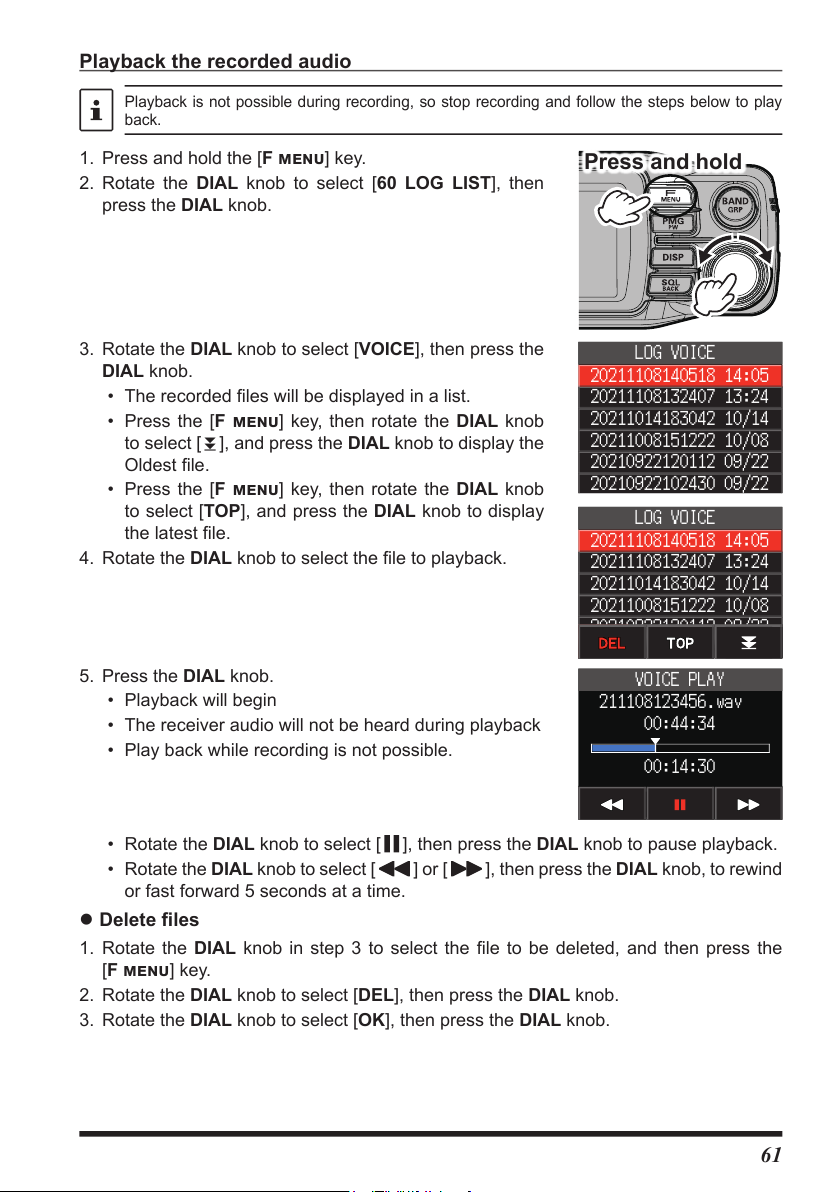
Playback the recorded audio
Press and hold
20210922102430 09/22
20191224102430 12/24
Playback is not possible during recording, so stop recording and follow the steps below to play
back.
1. Press and hold the [F menu] key.
2. Rotate the DIAL knob to select [60 LOG LIST], then
press the DIAL knob.
3. Rotate the DIAL knob to select [VOICE], then press the
DIAL knob.
• The recorded files will be displayed in a list.
• Press the [F menu] key, then rotate the DIAL knob
to select [
Oldest file.
• Press the [F menu] key, then rotate the DIAL knob
to select [TOP], and press the DIAL knob to display
the latest file.
4. Rotate the DIAL knob to select the file to playback.
5. Press the DIAL knob.
• Playback will begin
• The receiver audio will not be heard during playback
• Play back while recording is not possible.
• Rotate the DIAL knob to select [ ], then press the DIAL knob to pause playback.
• Rotate the DIAL knob to select [
or fast forward 5 seconds at a time.
z Delete files
1. Rotate the DIAL knob in step 3 to select the file to be deleted, and then press the
[F menu] key.
2. Rotate the DIAL knob to select [DEL], then press the DIAL knob.
3. Rotate the DIAL knob to select [OK], then press the DIAL knob.
], and press the DIAL knob to display the
] or [ ], then press the DIAL knob, to rewind
LOG VOICE
20211108140518 14:05
20211108132407 13:24
20211014183042 10/14
20211008151222 10/08
20210922120112 09/22
LOG VOICE
20211108140518 14:05
20211108132407 13:24
20211014183042 10/14
20211008151222 10/08
20210922120112 09/22
VOICE PLAY
211108123456.wav
00:44:34
00:14:30
61
Page 64

Taking a Picture (Snapshot Function)
Pictures can be taken by connecting the optional camera-equipped microphone (MH-
85A11U). Captured image data can be saved onto a MicroSD memory card inserted into
the transceiver. The saved data can be displayed on the screen and transmitted to other
transceivers* as well. In addition, the most recently captured image data can be transmitted
to other transceivers* by pressing
microphone.
* Refer to the Yaesu website or catalog for the compatible transceiver models.
(Send Image Button) on the camera-mounted
Send Image Button
Sends the most recently
taken image data.
Lens
Aim this part toward the object to photograph.
Do not touch the lens with fingers or other objects.
Shutter Button
PTT Switch
Press to enable transmission,
and release to return to
receive mode.
Connector
Connecting the microphone to the front
panel forcibly may cause damage.
Connect to the DATA
terminal of the Front Panel.
Make sure to insert the
connector in the right
direction.
Press to take a picture.
Microphone
Speak into this part
with a normal voice.
• Make sure to keep at least 20 inches (50cm) distance between the lens and the object. If the
object is too close, the picture will be out of focus, resulting in a blurred picture.
• You can set the size (resolution) and image quality (compression ratio) of the image to be shot
by the following operations:
Press and hold the [F menu] key → [115 USB CAMERA]
• If your station and the remote station are both in digital mode, you can transfer the image data
most recently taken by pressing .
• Set the digital mode in advance to transfer images to other radios.
• Do not directly photograph objects with strong light, such as the sun or other bright objects.
Doing so can cause malfunction.
• If the lens or the microphone gets dirty, use a dry, soft cloth to wipe off the contaminants.
"MH-85A11U" cannot be transmitted by the VOX function.
62
Page 65

Taking pictures
1. Turn the transceiver OFF.
2. Connect the camera-equipped microphone (MH-85A11U) to the DATA terminal of the
front panel.
Turn the transceiver OFF when connecting or disconnecting the MH-85A11U.
3. Press the
• The captured image appears on the Display.
• Press the [F menu] key, to temporarily turn OFF the display of [SAVE], [SEND],
[EDIT] and view the entire photo. Press the [F menu] key again to display [SAVE],
[SEND], [EDIT].
4. To save the image onto the MicroSD memory card, rotate the DIAL knob to select
[SAVE], then press the DIAL knob.
Press the [SQL back] key to return the display to the previous operating screen
without saving the image.
5. To transmit the saved image to other transceivers, press the
on the MH-85A11U.
Press the microphone PTT switch to cancel the picture transmission (it may take a while for
the transmission to be canceled).
(shutter button) on the MH-85A11U microphone to take a picture.
(Send Image Button)
Viewing the Saved Image
1. Press and hold the [F menu] key.
2. Rotate the DIAL knob to select [60 LOG LIST], then press the DIAL knob.
3. Rotate the DIAL knob to select [PICT], then press the DIAL knob.
Displays the saved image data list.
• Press the [F menu] key, then rotate the DIAL knob to select [
knob to display the oldest file.
• Press the [F menu] key, then rotate the DIAL knob to select [TOP], and press the
DIAL knob to display the latest file.
4. Rotate the DIAL knob to select the image to be displayed, then press the DIAL knob.
• The image will be displayed.
• Rotate the DIAL knob to display other saved images.
• Press the DIAL knob while an image is displayed, you can temporarily turn Off the
display information other than the image, such as the file name, and view the entire
photo. Press the DIAL knob again to display it again.
5. Press the [F menu] key.
6. Rotate the DIAL knob to select [SEND], then press the DIAL knob.
The confirmation screen will be displayed.
7. Rotate the DIAL knob to select [OK], then press the DIAL knob.
Image transmission starts.
8. Press the PTT switch to return to the normal screen.
], and press the DIAL
63
Page 66

Deleting saved images
1. Select [DEL] in step 6 above and press the DIAL knob.
The confirmation screen will be displayed.
2. Rotate the DIAL knob to select [OK], then press the DIAL knob.
The image is deleted.
Edit the tag (display name) of the saved image
1. Select [EDIT] in step 6 above and press the DIAL knob.
The image tag (display name) edit screen is displayed.
2. Rotate the DIAL knob to select a character and press the DIAL knob to confirm.
3. Repeat step 2 to edit the image tag (display name).
4. When you have finished editing, press and hold the DIAL knob.
The image tag (display name) is changed.
GPS Function
The FTM-200DR/DE is equipped with a GPS (Global Positioning System) receiver.
When receiving signals from GPS satellites, the current position (latitude, longitude,
altitude) can be calculated and displayed within a tolerance of several meters. In addition,
GPS receives the exact time from the satellite atomic clock.
For additional details on the GPS Function, refer to the Advanced Manual which may be
downloaded from the Yaesu website.
WIRES-X function
WIRES (Wide-coverage Internet Repeater Enhancement System) is an Internet
communication system which expands the range of amateur radio communications by
connecting with a local WIRES-X Node station. The FTM-200DR/DE can communicate
and exchange data via the internet with WIRES-X nodes worldwide. Use the News Station
function to write (upload) and read (download) digital data (text, images and audio).
When connected to a WIRES-X node station or room, the node name, room name, call
sign of the other station, distance, and direction, are all displayed on this screen.
For details, refer to the separate WIRES-X Instruction Manual which is available on the Yaesu
website.
APRS (Automatic Packet Reporting System) function
The FTM-200DR/DE uses a GPS receiver to acquire and display its position location
information. The APRS feature uses the location information to transmit the position
information, data and messages, using the format developed by Bob Bruninga WB4APR.
Upon receiving an APRS report from a remote station, the direction and distance to the
remote station from your station, the speed of the remote station, and other data sent by
the remote station may be displayed on the LCD of your transceiver.
Setting several station parameters, such as the call sign and symbol is required before
using the APRS function (initial settings).
For details, refer to the APRS Function Instruction Manual which is available on the Yaesu website.
64
Page 67

For additional details on the following Functions, refer to the Advanced Manual which may be
downloaded from the Yaesu website.
Digital Personal ID (DP-ID) feature
Digital Personal ID (DP-ID) feature opens the speaker audio only when a C4FM signal set
to the same DP-ID in the Digital Mode is received.
Tone squelch feature
The tone squelch opens the speaker audio only when a signal containing the specified
CTCSS tone is received. By matching the CTCSS tone frequency with the partner
stations, quiet standby monitoring is possible.
Digital Code squelch (DCS) feature
The DCS (Digital Coded Squelch) function allows audio to be heard only when signals
containing the same DCS code are received.
New PAGER (EPCS) feature
This new feature allows calling specified stations only, by using a pager code that combines
two CTCSS tones. Even when the person who is called is not near the transceiver, the
information is displayed on the LCD to indicate that a call was received. When the call is
received, the bell sounds.
65
Page 68

Using Setup Menu
Press and hold
The Set Mode permits configuring the various functions to accommodate individual
operating needs and preferences.
Setup Menu Operation
1. Press and hold the [F menu] key.
The Setup Menu screen will be displayed.
2. Rotate the DIAL knob to select the desired item in the
Setup Menu, then press the DIAL knob.
• Press the [SQL back] key to return to the previous
screen.
• Press the [UP] / [DWN] key on the microphone to jump
to the 17 categories in the Setup Menu below.
DISPLAY ↔ TX ↔ RX ↔ MEMORY ↔
CONFIG ↔ AUDIO ↔ SIGNALING ↔
SCAN ↔ DIGITAL ↔ GM ↔ WIRES-X ↔
DATA ↔ APRS ↔ SD CARD ↔ OPTION
↔
CLONE ↔ RESET
3. When there is no deeper level of menu items, go to step 4.
When there is a deeper level of menu items, rotate the DIAL knob to select the desired
item, then press the DIAL knob.
4. Rotate the DIAL knob to change the setting value.
5. Press any key (except Power Switch) or PTT switch to finish the setting and return to
the original screen.
DISPLAY
1
FREQUENCY INPUT >
2
LCD BRIGHTNESS
3
FREQUENCY COLOR
4
BAND SCOPE
>
66
Page 69

Tables of Setup Menu Operations
Menu Number / Item Description
DISPLAY
1 FREQUENCY INPUT
2 LCD BRIGHTNESS
3 FREQUENCY COLOR
4 BAND SCOPE
5 LOCATION INFO
6 COMPASS
7 DISPLAY MODE
Enter frequency directly or display
memory channel list.
Display and key button brightness. MIN / MID / MAX
Set the font color of the operation
band frequency.
Scope Display width setting. NARROW / WIDE
Switch between the compass screen
and the latitude/longitude display
screen when using the GPS and GM
functions.
Set the compass display of the
smart navigation function.
Back Track, Altitude, Timer/Clock or
GPS Information screen display.
TX
8 TX POWER
9 AMS TX MODE
10 MIC GAIN
11 VOX
12 AUTO DIALER
13 TOT
14 DIGITAL VW
Set the transmit power level. LOW / MID / HIGH
Set the AMS transmission mode. AUTO / TX FM FIXED/ TX DN FIXED
Microphone sensitivity setting. MIN / LOW / NORMAL / HIGH / MAX
VOX function settings. VOX: OFF / LOW / HIGH
DTMF code automatic transmit
setting.
TX time out setting. OFF / 1min / 2min / 3min /5min / 10min /
Turn the VW mode selection ON or
OFF.
Selectable options
Options in bold are the default set tings
(
-
WHITE / BLUE / RED
COMPASS / NUMERIC
NORTH UP / HEADING UP
BACKTRACK / ALTITUDE /
TIMER/CLOCK / GPS INFORMATION
DELAY: 0.5s / 1.0s / 1.5s / 2.0s / 2.5s / 3.0s
ON / OFF
15min / 20min / 30min
(Depends on the transceiver version)
ON / OFF
)
RX
15 FM BANDWIDTH
16 RX MODE
MEMORY
17 HOME
18 MEMORY LIST
19 MEMORY LIST MODE
20 PMG CLEAR
CONFIG
21 BEEP
Set the FM transmit modulation
level.
Select the receive mode. AUTO / FM / AM
Recall the home channel. Depends on the transceiver version.
Displays the Memory channel list
screen.
Displays a list of memory channels
in memory mode.
Cancel the registration of all PMG
channels.
Beep volume setting. OFF / LOW / HIGH
WIDE / NARROW
–
ON / OFF
–
67
Page 70

Menu Number / Item Description
Selectable options
Options in bold are the default set tings
(
)
22 BAND SKIP
23 RPT ARS
24 RPT SHIFT
25 RPT SHIFT FREQ
26 RPT REVERSE
27 MIC PROGRAM KEY
28 DATE&TIME ADJUST
29 DATE&TIME FORMAT
30 TIME ZONE
31 STEP
32 CLOCK TYPE
33 UNIT
34 APO
35 GPS DATUM
36 GPS DEVICE
37 GPS LOG
Set the frequency bands that can be
selected.
Repeater auto shift setting. OFF / AUTO
Repeater shift direction setting. AUTO / - / +
Repeater TX offset setting. 0.00MHz to 99.95MHz
Reverses the transmit and receive
frequencies while working through a
repeater.
Microphone P2 / P3 / P4 buttons
programable settings.
Set the date and time. -
Set the date and time display
formats.
Time zone setting.
Frequency tuning step.
Clock shift setting. A / B
Display unit setting. METRIC / INCH
Automatic power OFF time setting. OFF / 0.5hour to 12.0hour
GPS function positioning selection. WGS-84 / TOKYO MEAN
GPS receiver selection. INTERNAL / EXTERNAL
GPS access time setting. OFF / 1sec / 2sec / 5sec / 10sec /
AIR: ON / OFF
VHF: ON / OFF
UHF: ON / OFF
OTHER: ON / OFF
NORMAL / REVERSE
OFF / REC(STOP) / SCAN / HOME /
RPT SHIFT / REVERSE / TX POWER /
SQL OFF / T-CALL / VOICE* / D_X /
WX / STN LIST / MSG LIST / REPLY /
MSG EDIT / DW
(*requires optional FVS-2)
P1: GM (FIX)
P2: HOME
P3: D_X
P4: WX (T-CALL: European version)
Date: mmm/dd/yyyy / yyyy/mmm/dd /
dd/mmm/yyyy / yyyy/dd/mmm
Time: 24hours / 12hours
UTC -14:00 to
AUTO / 5.00 kHz / 6.25 kHz / (8.33 kHz)
/ 10.00 kHz / 12.50 kHz / 15.00kHz /
20.00kHz / 25.00 kHz / 50.00 kHz / 100 kHz
(Depends on the transceiver version)
(0.5 hour steps)
30sec / 60sec
±0:00 to +14:00
AUDIO
38 RECORDING
39 REC/STOP
SIGNALING
40 DTMF
41 DTMF MEMORY
42 SQL TYPE
68
Voice record function settings. BAND: A / B / A+B
Start and stop recording. –
Load DTMF Autodialer Memories. –
Set the DTMF auto dialer channel
and code (16 characters).
Select a squelch type. OFF / TONE ENC / TONE SQL /
MIC: ON / OFF
1 to 9
REV TONE / DCS / PR FREQ /
PAGER / (DCS ENC) / (TONE DCS) /
(DCS TSQL)
*The options in the parentheses are
available when the SQL expansion is ON.
Page 71

Menu Number / Item Description
Selectable options
Options in bold are the default set tings
(
)
43 TONE SQL FREQ
or
DCS CODE
44 SQL EXPANSION
45 PAGER CODE
46 PR FREQUENCY
47 BELL RINGER
48 WX ALERT
SCAN
49 SCAN
50 DUAL RCV MODE
51 DUAL RX INTRVAL
52 PRIORITY REVERT
53 SCAN RESUME
DIGITAL
54 DIGITAL POPUP
55 LOCATION SERVICE
56 STANDBY BEEP
Set the CTCSS Tone Frequency or
the DCS code.
Separate squelch type setting for
transmit and receive.
Pager individual code settings. RX-CODE 1: 01 - 05 - 50
User programmed reverse tone
frequency.
Recall sound length setting. OFF / 1 time / 3 times / 5 times /
Weather alert operation setting. ON / OFF
Engages the Scan operation. -
Dual receive operation setting. OFF / PRIORITY SCAN /
Dual receive reception interval
setting.
(Only enabled when "34 Dual
Receive Mode" is set to "PRIORITY
SCAN".)
The transmission operation during
dual receive always transmits on the
home channel.
Set the resume operation after
scanning stops on a signal.
Information screen popup time. OFF / 2sec / 4sec / 6sec / 8sec /
Set whether to send your current
location in digital mode.
Standby Beep setting. ON / OFF
CTCSS: 67.0Hzto254.1Hz (100Hz)
DCS: 023 to 754
ON / OFF
RX-CODE 2: 01 - 47 - 50
TX-CODE 1: 01 - 05 - 50
TX-CODE 2: 01 - 47 - 50
300Hz - 1500Hz - 3000Hz
8 times / CONTINUOUS
A-B DUAL RECEIVE
0.5sec / 1sec / 2sec / 3sec / 5sec /
7sec / 10sec
OFF / ON
BUSY / HOLD / 1sec / 3sec / 5sec
(Depends on the transceiver version)
10sec / 20sec / 30sec / 60sec /
CONTINUE
ON / OFF
GM
* Refer to the separate Operating Manual GM Edition for details on the functions.
57 DP-ID LIST
58 RANGE RINGER
59 RADIO ID
60 LOG LIST
Displays the DP-ID list screen. –
Set the bell sound when checking
for stations within sphere of
communications.
Specific transceiver ID is displayed. –
Display a list of recorded voices,
received messages and images.
ON / OFF
(cannot be edited)
–
69
Page 72

Menu Number / Item Description
(
Selectable options
Options in bold are the default set tings
WIRES-X
* Refer to the separate Operating Manual WIRES-X Edition for details on the functions.
61 RPT/WIRES FREQ
FREQUENCY
62 SEARCH SETUP
63 EDIT CATEGORYTAG
64 DELETE ROOM/NODE
65 WIRES DG-ID
Set the frequency to be used for
Repeater / WIRES-X.
Register the WIRES-X preset
frequency.
Set the WIRES ROOM selection
method.
Edit the category tag. C1 to C5
Delete a registered category. C1 to C5
Set the DG-ID number for WIRES-X. AUTO / 01 to 99
MANUAL / PRESET
Preset frequency: 146.550MHz
446.500MHz
HISTORY / ACTIVITY
DATA
66 COM PORT
67 DATA BAND
68 DATA SPEED
69 DATA SQL
COM port settings
APRS/DATA band selection settings. APRS:
APRS/DATA communication baud
rate settings.
Squelch detection settings. TX ON / TX OFF
SPEED: 4800bps / 9600bps /
OUTPUT: OFF / GPS OUT /
WP FORMAT: NMEA 6 /
WP FILTER: ALL / MOBILE /
MAIN BAND / SUB BAND
A-BAND FIX / B-BAND FIX /
DATA:
MAIN BAND / SUB BAND /
A-BAND FIX / B-BAND FIX /
APRS: 1200 bps / 9600 bps
DATA: 1200 bps / 9600 bps
19200bps / 38400bps /
57600bps
PACKET /WAYPOINT
NMEA 7 /NMEA 8 /
NMEA 9
FREQUENCY /
OBJECT/ITEM /
DIGIPEATER / VoIP /
WEATHER /YAESU /
CALL RINGER /
RANGE RINGER
)
/
APRS
* Refer to the separate Operation Manual APRS Edition for details on the functions.
70 APRS DESTINATION
71 APRS FILTER
Model code display Non-editable. APY200 (FIX)
Filter function settings. Mic-E: ON / OFF
POSITION: ON / OFF
WEATHER: ON / OFF
OBJECT: ON / OFF
ITEM: ON / OFF
STATUS: ON / OFF
OTHER: ON / OFF
RANGE LIMIT: ON / OFF
ALTNET: ON / OFF
70
Page 73
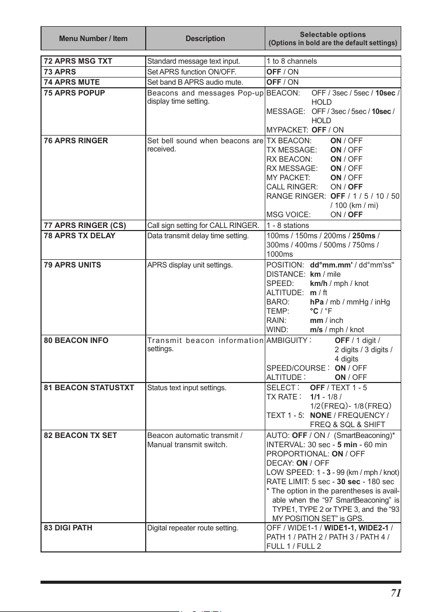
Menu Number / Item Description
Selectable options
Options in bold are the default set tings
(
)
72 APRS MSG TXT
73 APRS
74 APRS MUTE
75 APRS POPUP
76 APRS RINGER
77 APRS RINGER (CS)
78 APRS TX DELAY
79 APRS UNITS
80 BEACON INFO
81 BEACON STATUSTXT
82 BEACON TX SET Beacon automatic transmit /
83 DIGI PATH
Standard message text input. 1 to 8 channels
Set APRS function ON/OFF. OFF / ON
Set band B APRS audio mute. OFF / ON
Beacons and messages Pop-up
display time setting.
Set bell sound when beacons are
received.
Call sign setting for CALL RINGER. 1 - 8 stations
Data transmit delay time setting. 100ms / 150ms / 200ms / 250ms /
APRS display unit settings. POSITION: dd°mm.mm' / dd°mm'ss''
Transmit beacon information
settings.
Status text input settings. SELECT: OFF / TEXT 1 - 5
Manual transmit switch.
Digital repeater route setting. OFF / WIDE1-1 / WIDE1-1, WIDE2-1 /
BEACON: OFF / 3sec / 5sec / 10sec /
MES SAGE: OFF / 3sec / 5sec / 10sec /
MYPACKET: OFF / ON
TX BEACON: ON / OFF
TX MESSAGE: ON / OFF
RX BEACON: ON / OFF
RX MESSAGE: ON / OFF
MY PACKET: ON / OFF
CALL RINGER: ON / OFF
RANGE RINGER: OFF / 1 / 5 / 10 / 50
MSG VOICE: ON / OFF
300ms / 400ms / 500ms / 750ms /
1000ms
DISTANCE: km / mile
SPEED: km/h / mph / knot
ALTITUDE: m / ft
BARO: hPa / mb / mmHg / inHg
TEMP: °C / °F
RAIN: mm / inch
WIND: m/s / mph / knot
AMBIGUITY: OFF / 1 digit /
2 digits / 3 digits /
4 digits
SPEED/COURSE: ON / OFF
ALTITUDE: ON / OFF
TX RATE: 1/1 - 1/8 /
TEXT 1 - 5: NONE / FREQUENCY /
AUTO: OFF / ON / (
INTERVAL: 30 sec - 5 min - 60 min
PROPORTIONAL: ON / OFF
DECAY: ON / OFF
LOW SPEED:
RATE LIMIT: 5 sec - 30 sec - 180 sec
* The option in the parentheses
able when the “97 SmartBeaconing” is
TYPE1, TYPE 2 or TYPE 3, and the “93
MY POSITION SET” is GPS.
PATH 1 / PATH 2 / PATH 3 / PATH 4 /
FULL 1 / FULL 2
HOLD
HOLD
/ 100 (km / mi)
1/2(FREQ)-1/8(FREQ)
FREQ & SQL & SHIFT
SmartBeaconing
1 - 3 - 99 (km / mph / knot)
is avail-
)*
71
Page 74

Menu Number / Item Description
Selectable options
Options in bold are the default set tings
(
)
84 DIGI PATH 1
85 DIGI PATH 2
86 DIGI PATH 3
87 DIGI PATH 4
88 DIGI PATH FULL 1
89 DIGI PATH FULL 2
90 CALLSIGN (APRS)
91 MESSAGE GROUP
92 MESSAGE REPLY
93 MY POSITION SET
94 MY POSITION
95 MY SYMBOL
96 POSITION COMMENT
97 SmartBeaconing
98 SORT FILTER
99 VOICE ALERT
100 STATION LIST
Digital repeater route address
setting.
Digital repeater route address
setting.
My call sign setting.
Group filter setting for received
messages.
Set automatic response to received
messages.
My position setting. GPS / MANUAL
My position manual setting. LAT: N 0°00. 00' (' 00'')
My symbol setting. ICON 1: [/>] Car
Set position comment. Off Duty / En Route / In Service /
Smart beaconing settings. STATUS: OFF / TYPE1 / TYPE2 /
Sort function / Filter function settings. SORT: TIME / CALLSIGN / DISTANCE
Voice alert function settings. VOICE ALERT: NORMAL / TONE SQL
Displays the APRS Station list
screen.
ADDRESS 1: -
ADDRESS 2: -
ADDRESS 1: - to ADDRESS 8: -
******-**
GROUP 1: ALL
GROUP 2: CQ
GROUP 3: QST
GROUP 4: YAESU
GROUP 5: ----------
GROUP 6: ----------
BULLETIN 1: BLN?
BULLETIN 2: BLN?-----
BULLETIN 3: BLN?-----
REPLY: OFF / ON
CALLSIGN: ******-**
REPLY TEXT: -
LON: E 0°00. 00' (' 00'')
ICON 2: [/R] REC.Vehicle
ICON 3: [/-] House QTH (VHF)
USER: [YY] Yaesu Radios
Returning / Committed / Special /
Priority / Custom 0 to Custom 6 /
EMERGENCY!
* For details on the following setting
items for each type, refer to the APRS
Instruction Manual.
LOW SPD, HIGH SPD, SLOW RATE,
FAST RATE, TURN ANGL,
TURN SLOP, TURN TIME
FILTER: ALL / MOBILE / FREQUENCY /
TONE SQL: 67.0Hz - 100.0Hz -
DCS:023-754
******
*******
******
****
*****
TYPE3
OBJECT / ITEM / DIGIPEATER
/ VoIP / WEATHER / YAESU
/ OTHER PACKET / CALL
RINGER / RANGE RINGER /
1200 bps / 9600 bps
DCS / RX-TSQL /
RX-DCS
254.1Hz
–
72
Page 75

Menu Number / Item Description
Selectable options
Options in bold are the default set tings
(
)
101 MESSAGE LIST
102 BEACON TX SELECT
Displays the APRS Message list
screen.
Beacon automatic transmit / Manual
transmit switch.
–
MANUAL / AUTO / (SmartBeaconing)*
* The option in the parentheses
able when the “97 SmartBeaconing” is
TYPE1, TYPE 2 or TYPE 3, and the “93
MY POSITION SET” is GPS.
103 BEACON TX
Manual beacon transmission (one
time)
–
SD CARD
104 BACKUP
WRITE TO SD
ALL
MEMORY
SETUP
READ FROM SD
ALL
MEMORY
SETUP
105 MEMORY INFO
106 FORMAT
OPTION
107 Bluetooth (Requires optional Bluetooth
Bluetooth
DEVICE
SAVE
AUDIO
108 VOICE MEMORY (Requires optional Voice Guide Unit FVS-2)
PLAY/REC
ANNOUNCE
LANGUAGE
VOLUME
RX MUTE
109 FVS REC
110 TRACK SELECT
111 PLAY
112 STOP
113 CLEAR
114 VOICE GUIDE
115 USB CAMERA (Requires optional Microphone with Snapshot Camera MH-85A11U)
SIZE
QUALITY
Saves the transceiver setting information to a microSD memory card.
Copies all data.
Copies only the memory channels and backtrack position information.
Copies only the set-up menu settings.
Loads the information to the transceiver from a microSD memory card.
Copies all data.
Copies only the memory channels and backtrack position information.
Copies only the set-up menu settings.
Displays the total capacity and free
space of the MicroSD Card.
–
Initializing the micro-SD card. –
®
Unit BU-4)
Bluetooth headset setting. OFF / ON
Bluetooth device list. –
Turn the Bluetooth save function ON
OFF / ON
or OFF.
Set whether received audio is heard
from both the Bluetooth
the transceiver speaker, or only from
the connected Bluetooth
®
headset and
®
device.
AUTO / FIX
Recording operation settings. FREE 5min / LAST 30sec
Setting conditions for frequency
AUTO / OFF / MANUAL
announcement.
Setting the language to announce. ENGLISH / JAPANESE
Setting the announcement volume. HIGH / MID / LOW
Setting to mute received audio
ON / OFF
during announcements and
playback.
Start recording the received audio. –
Selecting the audio track to play. ALL / 1 - 8
Start playing the recorded sound –
Stop recording / playing –
Erase all recorded audio –
The frequency of the operating band
–
will be announced.
Picture size setting. 160×120 / 320×240
Picture quality setting. LOW / NORMAL / HIGH
is avail-
73
Page 76

Menu Number / Item Description
CLONE
116 This Other
117 Other This
Send all settings to other
FTM-200D
Receive all settings from other
FTM-200D
RESET
118 CALLSIGN
119 MEMORY CH RESET
120 APRS RESET
121 CONFIG SET
122 CONFIG RECALL
123 SOFTWARE VERSION
124 FACTORY RESET
My call sign setting. (10 characters)
Erase registered memory channels. –
Return APRS settings to default. –
Save configuration. –
Recall configuration. –
Display the software version. Main Ver. / Sub Ver. / DSP Ver.
Return all settings to factory default.
Selectable options
Options in bold are the default set tings
(
–
–
**********
–
)
74
Page 77

Restoring to Defaults (Reset)
When the All Reset function is performed, all data registered in the memory will be deleted. Be sure
to note the settings on paper or back up the data on a microSD memory card.
Caution
All Reset
To restore all transceiver settings and memory content to the factory defaults.
1. Press and hold the [F menu] key.
The Setup Menu screen will be displayed.
2. Press the DIAL knob to select [124 FACTORY RESET],
then press the DIAL knob.
“FACTORY RESET” appears on the LCD.
3. Rotate the DIAL knob to select [OK].
To cancel the resetting, select [CANCEL], then press the DIAL knob.
4. Press the DIAL knob to reset all.
After resetting all defaults, the call sign input message appears on the LCD. Set the
call sign (page page 4).
RESET
CONFIG SET121
CONFIG RECALL122
123
SOFTWARE VERSION >
124
FACTORY RESET
>
Memory Channels Reset
To erase only the registered all memory channels.
1. Press and hold the [F menu] key [119 MEMORY CH RESET]
“MEMORY CH RESET” appears on the LCD.
2. Rotate the DIAL knob to select [OK].
To cancel the resetting, select [CANCEL], then press the DIAL knob.
3. Press the DIAL knob to delete all memory contents.
APRS Reset
To restore all APRS settings to the factory defaults.
1. Press and hold the [F menu] key [120 APRS RESET]
“APRS RESET” appears on the LCD.
2. Rotate the DIAL knob to select [OK].
To cancel the resetting, select [CANCEL], then press the DIAL knob.
3. Press the DIAL knob to delete all APRS settings.
75
Page 78

Text input screen
The keyboard screen is displayed when entering the station call sign or memory channel tag.
z Character input method
1. Rotate the DIAL knob to select a character, then press
the DIAL knob.
• Repeat step 1 to enter additional characters.
When input is complete, press and hold the DIAL knob to
save the characters and return to normal operation.
Delete characters and operate the cursor
/ : Move the cursor to left/right in the text input area.
•
: Erase the character at the left of the cursor position.
•
: Enter a space at the cursor position.
•
z Alphabet Input
• Rotate the DIAL knob to select [
pressed, the input screen changes as follows:
• Rotate the DIAL knob to select [
input switches between small and capital letters.
1 byte letters 2 byte letters
] or [ ], and each time the DIAL knob is
], and each time the DIAL knob is pressed, the
z AlphaNumbers and Symbols Input
• Rotate the DIAL knob to select [
knob is pressed, the input screen changes as follows:
1 byte numbers 2 byte numbers 1 byte symbols 2 byte symbols
], [ ], [ ] or [ ] and each time the DIAL
76
Page 79

Specifications
z General
Frequency Range : TX 144 - 148MHz or 144 - 146MHz
:
Channel Steps : 5 / 6.25 / 8.33 / 10 / 12.5 / 15 / 20 / 25 / 50 / 100kHz
Mode of Emission : F1D, F2D, F3E, F7W
Frequency Stability : ± 2.5ppm (-4°F to +140°F [-20°C to +60°C])
Antenna Impedance : 50Ω
Supply Voltage : Nominal 13.8V DC, negative ground
Current Consumption (approx.) : 0.5 A (Receive)
Operating Temperature Range : -4°F to +140°F [-20°C to +60°C]
Case Size (W x H x D) Radio unit 5.47" x 1.66" x 5.2" (139 x 42 x 132 mm) (w/o Fan)
Weight (approx.) : 2.43lbs (1.1kg) (with Radio Unit, Controller, Control Cable)
z Transmitter
RF Power Output : 50W / 25W / 5W
430 - 450MHz or 430 - 440MHz
(Depends on the transceiver version)
RX 108 - 137MHz (AIR Band)
137 - 174MHz (144MHz HAM / VHF Band)
174 - 400MHz (GEN)
400 - 480MHz (430MHz HAM / UHF Band)
480 - 999.99MHz (GEN) (USA Cellular Blocked)
(8.33kHz: only for Air band)
11 A (50W TX, 144MHz)
11 A (50W TX, 430MHz)
Controller 5.47" x 2.09" x 0.7" (139 x 53 x 18mm) (w/o Knob)
Modulation Type : F1D, F2D, F3E: Variable Reactance Modulation
F7W: 4FSK(C4FM)
Maximum Deviation : ±5kHz
Spurious Emission : At least 60dB below
Microphone Impedance: 2kΩ
DATA Jack Impedance : 10kΩ
77
Page 80
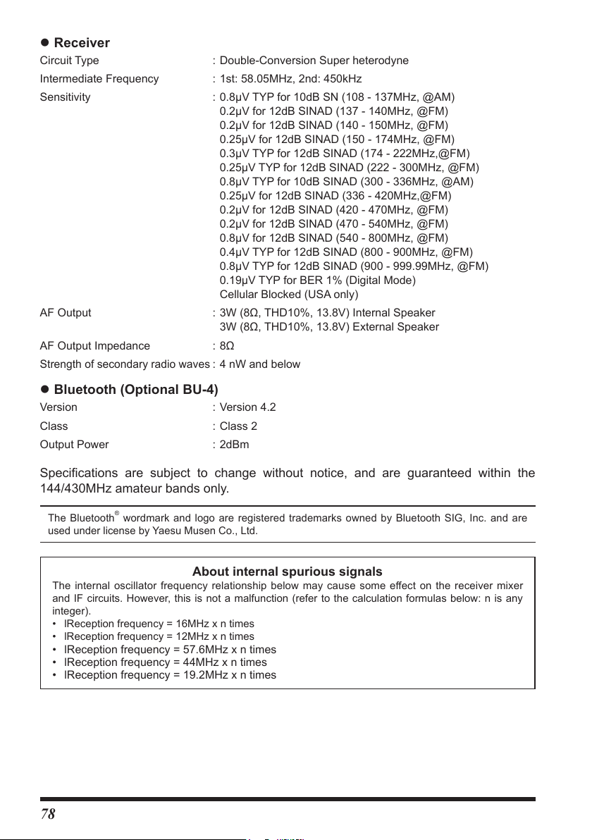
z Receiver
Circuit Type : Double-Conversion Super heterodyne
Intermediate Frequency : 1st: 58.05MHz, 2nd: 450kHz
Sensitivity : 0.8μV TYP for 10dB SN (108 - 137MHz, @AM)
0.2μV for 12dB SINAD (137 - 140MHz, @FM)
0.2μV for 12dB SINAD (140 - 150MHz, @FM)
0.25μV for 12dB SINAD (150 - 174MHz, @FM)
0.3μV TYP for 12dB SINAD (174 - 222MHz,@FM)
0.25μV TYP for 12dB SINAD (222 - 300MHz, @FM)
0.8μV TYP for 10dB SINAD (300 - 336MHz, @AM)
0.25μV for 12dB SINAD (336 - 420MHz,@FM)
0.2μV for 12dB SINAD (420 - 470MHz, @FM)
0.2μV for 12dB SINAD (470 - 540MHz, @FM)
0.8μV for 12dB SINAD (540 - 800MHz, @FM)
0.4μV TYP for 12dB SINAD (800 - 900MHz, @FM)
0.8μV TYP for 12dB SINAD (900 - 999.99MHz, @FM)
0.19μV TYP for BER 1% (Digital Mode)
Cellular Blocked (USA only)
AF Output : 3W (8Ω, THD10%, 13.8V) Internal Speaker
3W (8Ω, THD10%, 13.8V) External Speaker
AF Output Impedance : 8Ω
Strength of secondary radio waves
: 4 nW and below
z Bluetooth (Optional BU-4)
Version : Version 4.2
Class : Class 2
Output Power : 2dBm
Specifications are subject to change without notice, and are guaranteed within the
144/430MHz amateur bands only.
The Bluetooth® wordmark and logo are registered trademarks owned by Bluetooth SIG, Inc. and are
used under license by Yaesu Musen Co., Ltd.
About internal spurious signals
The internal oscillator frequency relationship below may cause some eect on the receiver mixer
and IF circuits. However, this is not a malfunction (refer to the calculation formulas below: n is any
integer).
• lReception frequency = 16MHz x n times
• lReception frequency = 12MHz x n times
• lReception frequency = 57.6MHz x n times
• lReception frequency = 44MHz x n times
• lReception frequency = 19.2MHz x n times
78
Page 81

Page 82

Copyright 2022
YAESU MUSEN CO., LTD.
All rights reserved.
No portion of this manual may be
reproduced without the permission of
YAESU MUSEN CO., LTD.
YAESU MUSEN CO., LTD.
Tennozu Parkside Building
2-5-8 Higashi-Shinagawa, Shinagawa-ku, Tokyo 140-0002 Japan
YAESU USA
6125 Phyllis Drive, Cypress, CA 90630, U.S.A.
YAESU UK
Unit 12, Sun Valley Business Park, Winnall Close
Winchester, Hampshire, SO23 0LB, U.K.
2202D-AS-1
Printed in Japan
 Loading...