

Page 1

FTM-3100R/E
Advance Manual
VHF FM TRANSCEIVER
VOL
REV
SQL
DW MW
TXPO
SETUP
DIAL
V/MMHz
Page 2

Contents
Basic Operation .............................................................................................................. 3
Microphone Gain Setting ................................................................................................ 3
RF Squelch .................................................................................................................... 3
Advanced Operation ...................................................................................................... 4
Programming the Key Assignments ............................................................................... 4
Tone Search ................................................................................................................... 6
DCS Search ................................................................................................................... 7
EPCS (Enhanced Paging & Code Squelch) Operation .................................................. 8
Storing CTCSS Tone Pairs for EPCS Operation .......................................................... 8
Activating the Enhanced Paging & Code Squelch System .......................................... 9
DTMF Operation .......................................................................................................... 10
Transmitting a DTMF code manually ......................................................................... 10
Registering a DTMF code .......................................................................................... 11
Transmitting the registered DTMF code.....................................................................12
Setting DTMF Autodialer sending Speed ................................................................... 12
Setting DTMF Autodialer TX delay time ..................................................................... 13
Memory Operation ........................................................................................................ 14
Split Memory ................................................................................................................ 14
Moving Memory Data to the VFO .............................................................................. 14
Memory Only Mode ...................................................................................................... 14
Naming a Memory Channel ......................................................................................... 15
Scanning ....................................................................................................................... 16
Scan Resume Options ................................................................................................. 16
Memory Skip Scanning ................................................................................................ 17
Preferential Memory Scan ............................................................................................ 18
Programmable Memory Scan (PMS) ........................................................................... 19
Registering to the programmable memory channels ................................................. 19
Scanning the programmable memory channels ........................................................ 20
Band Edge Beeper ....................................................................................................... 20
Priority Channel Scanning (Dual Watch) ...................................................................... 21
Priority Revert Mode .................................................................................................. 21
Clone .............................................................................................................................. 22
Setup (Menu) Mode ...................................................................................................... 23
Menu Selection Details ................................................................................................ 26
2
FTM-3100R/E Advance Manual
Page 3
Basic Operation
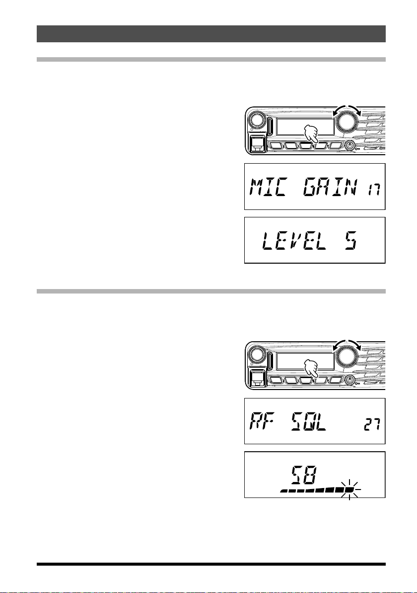
Microphone Gain Setting
The microphone gain has been programmed at the factory to a level that should be
satisfactory for the supplied MH-48A6JA Microphone. If an after-market microphone is
used, you may wish to set a different Mic Gain level.
1. Press and hold in the [MHz(SETUP)] key for
one second to enter the Set mode.
2. Rotate the DIAL knob to select “MIC GAIN
17”.
3. Press the [MHz(SETUP)] key, then rotate
the DIAL knob to select the desired microphone gain level (LEVEL 1 - LEVEL 9).
Default: LEVEL 5
4. Press and hold in the [MHz(SETUP)] key for
one second to save the new setting and exit
to normal operation.
RF Squelch
A special RF Squelch feature is provided on this radio, which allows setting the squelch so
that only signals exceeding a pre-set S-meter level will open the squelch.
Use the following procedure to set up the RF squelch circuit for operation:
1. Press and hold in the [MHz(SETUP)] key for
one second to enter the Set mode.
2. Rotate the DIAL knob to select “RF SQL 27”.
3. Press the [MHz(SETUP)] key, then rotate
the DIAL knob to select the desired signal
strength level for the squelch threshold (S1 S8 or OFF).
Default: OFF
4. Press and hold in the [MHz(SETUP)] key for
one second to save the new setting and exit
to normal operation.
VOL
VOL
REV
SQL
DW MW
REV
SQL
DW MW
TXPO
TXPO
DIAL
V/MMHz
SETUP
DIAL
V/MMHz
SETUP
3FTM-3100R/E Advance Manual
Page 4

Advanced Operation
Programming the Key Assignments
Default FTM-3100R/E key functions have been assigned to the Microphone [P1]/[P2]/
[P3]/[P4]
quick access to another function is desired.
Note: The default setting: [P1] - SQL OFF
To change the assignments for the programmable keys:
1. Press and hold in the [MHz(SETUP)] key
2. Press the [MHz(SETUP)] key, then rotate
The available program functions differ slightly for each of the four keys, the choices
Alternatively, one of the Set Menu items previously assigned may be set. To assign
3. Press and hold in the [MHz(SETUP)] key for one second to exit to normal operation.
keys at the factory. The user may change these key function assignments, if
[P2]
- HOME
[P3]
- CD SRCH
[P4]
- WX CH (T CALL: EXP/European version)
for one second, then rotate the DIAL knob
to select the Menu Item to configure the
desired microphone button: (“PRG P1 23”,
VOL
REV
SQL
DW MW
TXPO
DIAL
V/MMHz
SETUP
“PRG P2 24”, “PRG P3 25” or “PRG P4 26”).
the DIAL knob to select the function you
wish to assign to the key you selected in the
previous step.
include:
SQL OFF: Open the Squelch to allow un-muted reception.
HOME: Recall the home channel.
WX CH: Switches operation to the Weather channels bank.
CD SRCH: Engages the Tone or DCS Search Scanning feature.
SCAN: Engages the Scan operation.
T CALL: Activates 1750 Hz Tone Burst.
TX POWER: Set the transmission power level.
another desired Set Mode item to a programmable key, see the description in the box
shown below.
You may assign Set Mode items to the Microphone [P1]/[P2]/[P3]/[P4] buttons, as
well, to do this:
1. Press and hold in the [MHz(SETUP)] key for one second to enter the Set mode.
2. Rotate the DIAL knob to select the Set Mode Item that you wish to assign to the
key as a Menu short cut.
3. Press and hold in the Microphone’s [P1], [P2], [P3] or [P4] key for one second to
assign the Set Mode Item to that button.
4. Now you can recall this preferred Set Mode Item by simply pressing the
Microphone button momentarily.
4 FTM-3100R/E Advance Manual
Page 5

Advanced Operation
Split Tone Operation
The FTM-3100R/E can be configured to operate in a “Split Tone” system via the Setup
menu, to facilitate operation on repeaters using a mix of both CTCSS and DCS control.
1. Press and hold in the [MHz(SETUP)] key for
one second to enter the Set mode.
2. Rotate the DIAL knob to select “SQL EXP
33”.
3. Press the [MHz(SETUP)] key, then rotate
the DIAL knob to select “ON”.
Default: OFF
4. Press the [MHz(SETUP)] key momentarily,
then rotate the DIAL knob to select “SQL
TYPE 34”.
5. Press the [MHz(SETUP)] key, and then rotate the DIAL knob to select the following
parameters.
D CODE: DCS Encode only (the “DCS” icon
will blink during operation)
T DCS: Encodes a CTCSS Tone and
Decodes a DCS code (the “T”
icon will blink and the “DCS” icon
will appear during operation)
D TONE: Encodes a DCS code and
Decodes a CTCSS Tone (the “T
SQ” icon will appear and “DCS”
icons will blink during operation)
VOL
REV
SQL
DW MW
TXPO
DIAL
V/MMHz
SETUP
FTM-3100R/E Advance Manual
5
Page 6

Advanced Operation
Tone Search
When the CTCSS tone being transmitted by another station is not known, you can tune
the radio to the incoming signal and activate tone scan to search for and identify the tone
being used.
To scan for the tone in use:
1. Set the transceiver up for CTCSS Decoder operation (see the description in the box
shown below.).
“T SQ” will appear on the display.
2. Press the Programmable key on the MH-48A6JA Microphone that is assigned “CD
SRCH” (see page 4) to start scanning for the incoming CTCSS code.
3. When the radio detects the correct tone, scanning will halt on that tone, and audio will
be allowed to pass.
4. Press the assigned Programmable key of the Microphone to lock in that tone and exit
to normal operation.
Note: You may listen to the (muted) signals from the other stations during Tone Scanning
when Set Mode Item “TS MUTE 39” is set to “OFF”. See page 31 for details.
You can also change the Tone Search scanning speed, using Set Mode Item “TS
SPEED 40” See page 32 for details.
CTCSS Decoder Operation
1. Press and hold in the [MHz(SETUP)] key for one second to enter the Set mode.
2. Rotate the DIAL knob to select “SQL TYPE 34”.
3. Press the [MHz(SETUP)] key, and then rotate the DIAL knob to select “TSQL”.
4. Press and hold in the [MHz(SETUP)] key for one second to save the new
setting and exit to normal operation.
6
FTM-3100R/E Advance Manual
Page 7

Advanced Operation
DCS Search
When the DCS code being transmitted by another station is not known, you can tune the
radio to the incoming signal and activate DCS code scan to search for and identify the
DCS code being used.
To scan for the DCS in use:
1. Set the transceiver up for DCS operation
(see the description in the box shown below.).
“DCS” will appear on the display.
2. Press the Programmable key on the MH-48A6JA Microphone that is assigned “CD
SRCH” (see page 4) to start scanning for the incoming DCS code.
3. When the radio detects the correct code, scanning will halt on that code, and audio will
be allowed to pass.
4. Press the assigned Programmable key of the Microphone to lock in that tone and exit
to normal operation.
Note: You may listen to the (muted) signals from the other stations during DCS Scanning
when Set Mode Item “TS MUTE 39” is set to “OFF”. See page 31 for details.
You can also change the DCS Search scanning speed, using Set Mode Item “TS
SPEED 40” See page 32 for details.
DCS Operation
1. Press and hold in the [MHz(SETUP)] key for one second to enter the Set mode.
2. Rotate the DIAL knob to select “SQL TYPE 34”.
3. Press the [MHz(SETUP)] key, and then rotate the DIAL knob to select “DCS”.
4. Press and hold in the [MHz(SETUP)] key for one second to save the new
setting and exit to normal operation.
FTM-3100R/E Advance Manual
7
Page 8

Advanced Operation
EPCS (Enhanced Paging & Code Squelch) Operation
The FTM-3100R/E includes an Enhanced CTCSS tone encoder/decoder and a dedicated
microprocessor providing paging and selective calling features. This allows placing a call
to a specific station (Paging), and choosing to receive calls directed only to you (Code
Squelch).
The paging and code squelch systems use two pairs of (alternately switched) CTCSS
tones, which are stored in the pager memories. Basically, your receiver remains silent until
it receives the CTCSS tone pair that matches those stored in the Receiving Pager Memory.
The squelch then opens so the caller is heard, and the paging ringer immediately sounds,
if activated. When you close the PTT switch to transmit, the CTCSS tone pair that is
stored in the Transmitting Pager Memory will be transmitted automatically.
On the paged radio, the squelch will close automatically after the incoming page ends.
Storing CTCSS Tone Pairs for EPCS Operation
1. Press and hold in the [MHz(SETUP)] key for
one second to enter the Set mode.
2. Rotate the DIAL knob to select “PAG CD-R
21” for the Receiving CTCSS Tone Pair or
“PAG CD-T 22” for the Transmitting CTCSS
Tone Pair.
VOL
REV
SQL
DW MW
TXPO
DIAL
V/MMHz
SETUP
3. Press the [MHz(SETUP)] key momentarily to
enable adjustment of this Set Mode Item.
4. Rotate the DIAL knob to set the CTCSS
Tone number, which corresponds to the first
tone of the CTCSS Tone Pair.
5. Press the [SQL] or [V/M(MW)] key, then rotate the DIAL knob to set the CTCSS Tone
number, which corresponds to the second
tone of the CTCSS Tone Pair.
6. Press and hold in the [MHz(SETUP)] key for one second to lock in that tone and exit to
normal operation.
Note: The FTM-3100R/E does not recognize the order of the 1st tone and the 2nd tone.
In other words, for example, the FTM-3100R/E considers both CTCSS pairs “05,
47” and “47, 05” to be identical.
8
FTM-3100R/E Advance Manual
Page 9

Advanced Operation
Activating the Enhanced Paging & Code Squelch System
1. Press and hold in the [MHz(SETUP)] key for
one second to enter the Set mode.
2. Rotate the DIAL knob to select “SQL TYPE
34”.
3. Press the [MHz(SETUP)] key, and then
rotate the DIAL knob to select “PAGER”.
4. Press and hold in the [MHz(SETUP)] key for one second to save the new setting and
exit to normal operation.
5. To disable the Enhanced Paging & Code Squelch, just repeat the above procedure,
rotating the DIAL knob to select “OFF” in step 3 above.
When the Enhanced Paging & Code Squelch
feature is activated, the “P” notation will appear
on the right of the frequency display.
VOL
REV
SQL
DW MW
TXPO
DIAL
V/MMHz
SETUP
FTM-3100R/E Advance Manual
9
Page 10

Advanced Operation
DTMF Operation
DTMF tones (Dual Tone Multi Frequencies) are the tones you hear when dialing from a
telephone keypad. The FTM-3100R/E transceiver can transmit the DTMF codes by using
the keys on the microphone or recalling registered number strings from memories.
The maximum of 16-digit DTMF codes can be registered in up to 10 memory channels.
It is convenient to register telephone patch numbers, and network linking sequences to
the DTMF memory channels.
Note: The two combined frequencies of the DTMF tone transmitted for each key are
indicated in the following table:
1209 Hz 1336 Hz 1477 Hz 1633 Hz
697 Hz 1 2 3 A
770 Hz 4 5 6 B
852 Hz 7 8 9 C
941 Hz
]
Transmitting a DTMF code manually
You can generate DTMF tones during transmission manually.
1. Press and hold in the [MHz(SETUP)] key for
one second to enter the Set mode.
2. Rotate the DIAL knob to select “DT AUTO
10”.
0 # D
VOL
REV
SQL
DW MW
TXPO
DIAL
V/MMHz
SETUP
3. Press the [MHz(SETUP)] key momentarily, and then rotate the DIAL knob to select
“MANUAL”.
4. Press and hold in the [MHz(SETUP)] key for one second to save the new setting and
exit to normal operation.
[
5. While pressing and holding PTT, press the desired DTMF characters ([0] to [9],
]
], [#]
or [A] to [D]), sequentially on the microphone keypad.
6 Release PTT.
While transmitting the DTMF code, transmission status is sustained even when PTT is
released.
10
FTM-3100R/E Advance Manual
,
Page 11

Advanced Operation
Registering a DTMF code
1. Press and hold in the [MHz(SETUP)] key for
one second to enter the Set mode.
2. Rotate the DIAL knob to select “DT SET 12”.
3. Press the [MHz(SETUP)] key momentarily,
then rotate the DIAL knob to select the desired memory channel (C0 to C9) to register
the DTMF code.
4. Press the [TXPO] key momentarily, then rotate the DIAL knob to select the first digit of
the DTMF code.
Note: You can also use the keypad on the
microphone to input the DTMF code.
5. When you have selected the correct digit,
press the [V/M(MW)] key momentarily. Now,
rotate the DIAL knob to select the second of
16 available numbers in the current DTMF
Autodialer memory register.
6. Repeat this procedure for each digit in the DTMF code.
Note: m To make a correction, press the [SQL] key to back-space the cursor, then
re-enter the correct number.
m Press and hold in the [REV(DW)] key for one second to delete all data after
the cursor that may have been previously stored.
7. When entry of all digits is complete, press and hold in the [MHz(SETUP)] key for one
second to set the DTMF code and exit to normal operation.
VOL
REV
SQL
DW MW
TXPO
DIAL
V/MMHz
SETUP
FTM-3100R/E Advance Manual
11
Page 12

Advanced Operation
Transmitting the registered DTMF code
1. Press and hold in the [MHz(SETUP)] key for
one second to enter the Set mode.
2. Rotate the DIAL knob to select “DT AUTO
10”.
3. Press the [MHz(SETUP)] key momentarily, and then rotate the DIAL knob to select
“AUTO”.
4. Press and hold in the [MHz(SETUP)] key for one second to save the new setting and
exit to normal operation.
Note: While the DTMF Autodialer is activat-
ed, the “
” icon will appear on the
LCD.
5. In the Autodialer mode, which you just engaged, first press the PTT switch, then press
the microphone numeric key ([0] through [9]) corresponding to the DTMF memory
string you wish to send. Once the string begins, you may release the PTT switch, as
the transmitter will be held “on the air” until the DTMF string is completed.
To disable the Autodialer function mode, select “MANUAL” in step 3 above.
Setting DTMF Autodialer sending Speed
The speed at which the DTMF digits are sent can be changed.
1. Press and hold in the [MHz(SETUP)] key for
one second to enter the Set mode.
2. Rotate the DIAL knob to select “DT SPEED
13”.
3. Press the [MHz(SETUP)] key momentarily,
and then rotate the DIAL knob to select the
desired speed (“50 MS”: High speed or “100
MS”: Low speed).
4. Press and hold in the [MHz(SETUP)] key for
one second to save the new setting and exit
to normal operation.
VOL
VOL
REV
SQL
DW MW
REV
SQL
DW MW
TXPO
TXPO
DIAL
V/MMHz
SETUP
DIAL
V/MMHz
SETUP
12
FTM-3100R/E Advance Manual
Page 13

Advanced Operation
Setting DTMF Autodialer TX delay time
A longer delay may be set between the time the transmitter is keyed and the first DTMF
digit is sent:
1. Press and hold in the [MHz(SETUP)] key for
one second to enter the Set mode.
2. Rotate the DIAL knob to select “DT DELAY
11”.
3. Press the [MHz(SETUP)] key momentarily,
and then rotate the DIAL knob to select the
desired delay time (50 MS / 250 MS / 450
MS / 750 MS / 1000 MS).
Default: 450 MS
4. Press and hold in the [MHz(SETUP)] key for
one second to save the new setting and exit
to normal operation.
VOL
REV
SQL
DW MW
TXPO
DIAL
V/MMHz
SETUP
FTM-3100R/E Advance Manual
13
Page 14

Memory Operation
Split Memory
A separate transmit frequency may be registered to a memory channel to which a receive
frequency has already been registered.
1. In the VFO mode, select the transmit frequency to be registered.
2. Press and hold the [V/M(MW)] key for one second.
A memory number will appear in the bottom right corner of the display.
3. With in five seconds of pressing [V/M(MW)] key, rotate the DIAL knob (if necessary) to
select the memory channel to which the transmit frequency is to be registered.
4. Press and hold in the PTT, and press the [V/M(MW)] key momentarily while holding in
the PTT. This will not cause transmission, but rather it will instruct the transceiver to
program the separate transmit frequency into memory.
Whenever a memory which contains independently stored transmit and receive frequencies is recalled, the “
in the display.
Moving Memory Data to the VFO
The data stored on a memory channel can easily be moved to the VFO.
1. Select the memory channel containing the frequency data to be moved to the VFO.
2. Press and hold in the [V/M(MW)] key for one
second, and then press the [MHz(SETUP)]
key. The “VFO WRT?” will appear on the display.
3. Press the [MHz(SETUP)] key, the data will now have been copied to the VFO, although
the original memory contents will remain intact on the previously-stored channel.
Note: If a split Frequency Memory channel was transferred, the TX frequency will be
ignored (The transceiver will be set up for Simplex operation on the Receive
frequency.)
-
+” indication will appear
Memory Only Mode
When memory channel programming has been completed, you may place the radio in
a “Memory Only” mode, whereby VFO operation is impossible. This may be particularly
useful during public-service events where a number of operators may be using the radio
for first time, and ultimate simplicity of channel selection is desired.
To place the radio into the Memory Only mode, turn the transceiver OFF. Now press and
hold in the [V/M(MW)] key while turning the transceiver ON. The VFO and Home Channel
will now be disabled.
To return to normal operation, repeat the above power-on procedure.
14 FTM-3100R/E Advance Manual
Page 15

Memory Operation
Naming a Memory Channel
You may wish to append an alphanumeric “Tag” (label) to each memory, to aid in
recollection of the channel’s use (such as club name, etc.).
1. Recall the memory channel on which you wish to append a label.
2. Press and hold in the [MHz(SETUP)] key for
one second to enter the Set mode.
3. Rotate the DIAL knob to select “MEM NAME
18”.
4. Press the [MHz(SETUP)] key momentarily to
enable programming of the nametag.
5. Rotate the DIAL knob to select the first digit
of the desired label.
6. Press the [V/M(MW)] key to move to the next
character.
Note: To make a correction, press the [SQL]
key to back-space the cursor, then
re-enter the correct letter, number, or
symbol.
7. Repeat steps 5 through 6 to program the remaining letters, numbers, or symbols of the
desired label. A total of 8 characters may be
used in the creation of a label.
8. When you have programmed a label that is
under 8 characters, press the [MHz(SET-
UP)] key to confirm the label.
VOL
REV
SQL
DW MW
TXPO
DIAL
V/MMHz
SETUP
Note: Press and hold in the [REV(DW)] key for one second to delete all data after the
cursor that may have been previously stored.
9. When you have completed the creation of the label, then press and hold in the
[
V/M(MW)] key for one second to save the label and exit.
While operating in the Memory Recall mode,
press the [MHz(SETUP)] key to toggle the
display between indication of the frequency,
and indication of the Alpha/Numeric label.
FTM-3100R/E Advance Manual
15
Page 16

Scanning
Scan Resume Options
Select one of the three receiving operations to be performed after the scanning stops.
(1) Restart scanning after receiving the frequency for the set amount of time. Select from
2.0 to 10.0 seconds (0.5 step).
(2) Continue receiving the frequency until the signal disappears, and then restart scan-
ning 2 seconds after the signal disappears (BUSY).
(3) Stop scanning and receive that frequency (HOLD).
1. Press and hold in the [MHz(SETUP)] key for
one second to enter the Set mode.
2. Rotate the DIAL knob to select “SCAN RSM
31”.
3. Press the [MHz(SETUP)] key, then rotate
the DIAL knob to select the desired scan-resume mode.
Default: 5.0 SEC
4. Press and hold in the [MHz(SETUP)] key for
one second to save the new setting and exit
to normal operation.
VOL
REV
SQL
DW MW
TXPO
DIAL
V/MMHz
SETUP
16 FTM-3100R/E Advance Manual
Page 17

Scanning
Blinks
Blinks
Memory Skip Scanning
When some memory channels are continuously active, you may wish to skip them during
scanning, but still have them available for manual selection.
To mask a memory to be skipped (only) during scanning, use the following procedure:
1. Set the radio to the Memory Recall mode by
pressing the [V/M(MW)] key repeatedly, as
necessary, until
“ ”
and a channel number
appear on the right side of the display.
2. Rotate the DIAL knob to select the Memory
Channel to be skipped during scanning.
3. Press and hold in the [MHz(SETUP)] key for
one second, then rotate the DIAL knob to
select “SCAN SKP 32”.
4. Press the [MHz(SETUP)] key, then rotate
the DIAL knob to select “SKIP”. The current
Memory Channel will now be ignored during
scanning.
5. Press and hold in the [MHz(SETUP)] key for
one second to save the new setting and exit
to normal operation.
VOL
VOL
REV V/MMHz
SQL
DW MW
REV
SQL
DW MW
TXPO
TXPO
DIAL
SETUP
DIAL
V/MMHz
SETUP
A blinking “ ” icon will appear when you recall
the “skipped” memory channel manually.
To reinstate a channel into the scanning loop,
select “OFF” in step 4 above, after first recalling
the currently blocked channel (the “Skipped”
channel is accessible via manual channel
selection methods using the DIAL knob in the
Memory mode, whether or not it is locked out of
the scanning loop).
FTM-3100R/E Advance Manual
17
Page 18

Scanning
Preferential Memory Scan
The FTM-3100R/E also allows setting up a “Preferential Scan List” of channels, which you
can “flag” within the memory system. The flagged channels are designated by an
when they are selected, one by one, for the Preferential Scan List.
When memory scanning is initiated beginning on a channel with the
those channels bearing the
which does not have the
“ ”
icon will be scanned. If scanning is initiated on a channel
“ ”
icon appended, all channels including those with the
“ ”
icon appended, only
appended will be scanned.
Here is the procedure for setting up and using the Preferential Scan List:
1. Set the radio to the Memory Recall mode by
pressing the [V/M(MW)] key repeatedly, as
necessary, until
“ ”
and a channel number
appear on the right side of the display.
VOL
REV V/MMHz
SQL
DW MW
TXPO
SETUP
2. Rotate the DIAL knob to select the Memory
Channel that you wish to add to the preferential Scan List.
3. Press and hold in the [MHz(SETUP)] key for
one second, then rotate the DIAL knob to
select “SCAN SKP 32”.
VOL
REV
SQL
DW MW
TXPO
SETUP
“ ”
icon
“ ”
icon
DIAL
DIAL
V/MMHz
4. Press the [MHz(SETUP)] key, and then rotate the DIAL knob to select “SELECT”.
5. Press and hold in the [MHz(SETUP)] key for
one second to save the new setting and exit
to normal operation.
To initiate Preferential Memory Scanning:
1. Set the radio to the Memory Recall mode by pressing the [V/M(MW)] key repeatedly, if
necessary.
2. Rotate the DIAL knob to select any memory
channel which has an “
” icon appended to
the channel number.
3. Press and hold in either the microphone [UP] or [DWN] button for one second to initiate
Preferential Memory Scanning. Only the channels which have a “
” icon appended to
the channel number will be scanned.
18
FTM-3100R/E Advance Manual
Page 19

Scanning
Programmable Memory Scan (PMS)
The FTM-3100R/E
lower and band limits.
Example: Set up a PMS channel by registering a lower frequency of 144.300 MHz, and
Registering to the programmable memory channels
1. In the VFO mode, select the desired lower-limit scan frequency (144.300 MHz).
2. Press and hold the [V/M(MW)] key for one
second.
A memory number will appear in the bottom
right corner of the display.
3. Within five seconds of pressing the
[
V/M(MW)] key, rotate the DIAL knob to se-
lect “L1”.
Note: While operating in the Memory Storage mode, the keypad of the MH-48A6JA
Microphone may be used to enter the memory channel number directly.
To do this, enter the desired Channel Number (see table below) on the keypad
and then press the [#] key.
To enter Memory Channel “L1”, press [2] à [0] à [1] à [#
To enter Memory Channel “U0”, press [2] à [2] à [0] à [#
can be set to tune or scan only the frequencies between user-defined
an upper frequency of 148.000 MHz to the L1/U1 memory channels.
VOL
REV V/MMHz
SQL
TXPO
DW MW
SETUP
]
]
DIAL
L1 201 L3 205 L5 209 L7 213 L9 217
U1 202 U3 206 U5 210 U7 214 U9 218
L2 203 L4 207 L6 211 L8 215 L0 219
U2 204 U4 208 U6 212 U8 216 U0 220
4. Press the [V/M(MW)] key again, momentarily, to store the displayed data into the
memory channel (L1).
5. Select the desired upper-limit scanning frequency (148.000 MHz).
6. Within five seconds of pressing the
[
V/M(MW)] key, rotate the DIAL knob to se-
lect “U1”.
7. Press the [V/M(MW)] key again, momentarily, to store the displayed data into the memory channel (U1).
FTM-3100R/E Advance Manual
19
Page 20

Scanning
Scanning the programmable memory channels
1. Press the [V/M(MW)] key to enter memory mode.
2. Turn the DIAL knob, or use the microphone keypad, to recall the upper or lower frequency PMS memory channel (L1 or U1).
3. Press the [#] key on the MH-48A6JA Microphone.
“P1” appear on the right side of the display.
4. Press and hold [UP] or [DWN] on the microphone for over one second.
Programmable memory scanning will begin.
Note: To stop programmable memory scanning, press PTT on the microphone (this does
not cancel PMS mode).
To cancel PMS mode, when programmable memory scanning stops, press the [#]
key on the MH-48A6JA Microphone.
Band Edge Beeper
The FTM-3100R/E will automatically “beep” when the receive band edge is encountered
during scanning (either in standard VFO scanning or during PMS operation). Additionally,
the band edge beep feature may be enabled to sound when the band edge frequency is
reached while tuning the VFO, using the DIAL knob.
The procedure to enable the Band-Edge Beeper (during manual tuning) is:
1. Press and hold in the [MHz(SETUP)] key for
one second, then rotate the DIAL knob to
select “BEP EDGE 4”.
2. Press the [MHz(SETUP)] key, and then rotate the DIAL knob to set this Menu item to
“ON”.
3. Press and hold in the [MHz(SETUP)] key for
one second to save the new setting and exit
to normal operation.
VOL
REV
SQL
DW MW
TXPO
DIAL
V/MMHz
SETUP
20
FTM-3100R/E Advance Manual
Page 21

Scanning
Priority Channel Scanning (Dual Watch)
The FTM-3100R/E’s scanning features include a two-channel scanning capability which
allows operating on a VFO, Memory channel, or Home channel, while periodically checking
a user-defined Memory Channel for activity. If a station received on the Memory Channel is
strong enough to open the Squelch, the scanner will pause on that station in accordance with
the Scan-Resume mode setting of Menu item “SCAN RSM 31.” See page 16.
Here is the procedure for activating Priority Channel Dual Watch operation:
1. Set the transceiver to the Memory Recall mode by pressing the [V/M(MW)] key repeatedly, if necessary.
2. Press and hold in the [V/M(MW)] key for one second, then select the memory channel
you wish to be the “Priority” channel.
3. Press the [TXPO] key momentarily. The “PRI
CH?” will appear on the display.
4. Press the [TXPO] key momentarily. The “P”
notation will appear on the “100 MHz” frequency digit on the display; indicating it is
the Priority channel.
5. Now set the FTM-3100R/E for operation on
another memory channel, Home channel, or
on a VFO frequency.
6. Press and hold in the [REV(DW)] key for one second. The display will remain on the
VFO, the selected memory channel, or the Home channel, but every five seconds the
FTM-3100R/E will check the Priority Channel for activity.
Note: During Dual Watch operation, the decimal points of the frequency display blink.
7. To cancel Dual Watch operation, press and hold the [REV(DW)] key for one second.
Priority Revert Mode
During Priority channel operation (Dual Watch), a special feature is available which will
allow you to move to the Priority Channel instantly, without waiting for activity to appear
on the Priority Channel.
When this feature is enabled, and priority monitoring is engaged, just press the microphone
PTT switch. Operation will instantly revert to the Priority Channel.
1. Press and hold in the [MHz(SETUP)] key for
one second, then rotate the DIAL knob to
select “DW RVRT 14”.
2.
Press the [MHz(SETUP)] key, and then rotate
the DIAL knob to set this Menu item to “ON”.
3. Press and hold in the [MHz(SETUP)] key for
one second to save the new setting and exit
to normal operation.
To disable Priority Revert operation, select “OFF” in step 2 above.
FTM-3100R/E Advance Manual
21
Page 22

Clone
Pin 1: PTT/CLONE
Pin 3: GND
The FTM-3100R/E includes a convenient “Clone” feature, which allows the memory and
configuration data from one transceiver to be transferred to another FTM-3100R/E.
This can be particularly useful when configuring a number of transceivers for a public
service operation.
Here is the procedure for cloning data from one radio to another:
1. Turn both radios OFF.
2. Connect the user-constructed cloning cable between the MIC jacks of the two radios.
3. Press and hold in the [MHz(SETUP)] key
while turning the radios ON. Do this for both
radios (the order of switch-on does not matter). “CLONE” will appear on the displays of
both radios when the Clone mode is successfully activated in this step.
4. On the Destination radio; press the [MHz
(-
SETUP)] key (“-- --WAIT-- --” will appear on
the display).
5. On the Source radio; press the [REV(DW)]
key “-- -- --TX-- -- --” will appear on the
Source radio, and the data from this radio
will be transferred to the destination radio.
6. If there is a problem during the cloning process, “ERROR” will be displayed. Check
your cable connections and battery voltage,
and try again.
7. If the data transfer is successful, “CLONE”
will appear on the Source radio display. The
destination radio, to which the data is copied, will restart automatically.
8. Turn both radios off and disconnect the cloning cable.
VOL
REV
SQL
DW MW
TXPO
DIAL
V/MMHz
SETUP
VOL
REV
SQL
TXPO
DW MW
RJ12/6
6 Position 6 Contact
Modular Plug
DIAL
V/MMHz
SETUP
VOL
REV
SQL
TXPO
DW MW
RJ12/6
6 Position 6 Contact
Modular Plug
DIAL
V/MMHz
SETUP
Pin 1: PTT/CLONEPin 3: GND
22 FTM-3100R/E Advance Manual
Page 23

Setup (Menu) Mode
The FTM-3100R/E Setup (Menu) mode, already described in parts of many previous
chapters, is easy to activate and setup. The Menus may be used to configure many
of transceiver parameters, some of which have not been detailed previously. Use the
following procedure to activate the Setup (Menu) mode:
1. Press and hold the [MHz(SETUP)] key for
one second to enter the Setup menu.
2. Rotate the DIAL knob to select the Menu
Item to be adjusted.
3. Press the [MHz(SETUP)] key momentarily
to enable adjustment of the selected Menu
item, and then rotate the DIAL knob to perform the actual adjustment.
4. After completing the selection and adjustment, press and hold the [MHz(SETUP)] key
for one second to exit the Setup menu and
resume normal operation.
Menu Item Function Available Values Default
1: APO
2: BCLO
3: BEP KEY
4: BEP EDGE
5: BELL
6: CLK TYPE
7: DC VOLT
8: DCS CODE
9: DCS INV
10: DT AUTO
11: DT DELAY
12: DT SET
13: DT SPEED
14: DW RVRT
Enables/Disables the Automatic Power
Off feature.
Enables/Disables the Busy Channel
Lock-Out feature.
Enables/Disables the key beeper. KEY+SCAN/KEY/OFF KEY+SCAN
Enables/Disable the Band-edge beeper
while scanning.
Selects the CTCSS/DCS/EPCS Bell
Ringer repetitions.
Shifting of the CPU clock frequency. A/B A
Indicates the DC Supply Voltage. --- ---
Setting of the DCS code.
Select a combination of DCS inversion
codes in terms of communication direction.
Enables/Disables the DTMF Autodialer
feature.
Setting of the DTMF Autodialer TX Delay
Time.
Loading of the DTMF Autodialer Memories.
Setting of the DTMF Autodialer Sending
Speed.
Enables/Disables the “Priority Channel
Revert” feature.
VOL
REV
SQL
TXPO
DW MW
0.5H to 12H (0.5H step)/
OFF
DIAL
V/MMHz
SETUP
OFF
ON/OFF OFF
ON/OFF OFF
1 to 20/CONTINUE/OFF OFF
104 standard DCS
codes
NORMAL/INVERT/
BOTH
023
NORMAL
MANUAL/AUTO MANUAL
50/250/450/750/1000 450 MS
--- ---
50/100 50 MS
ON/OFF OFF
23FTM-3100R/E Advance Manual
Page 24

Setup (Menu) Mode
Menu Item Function Available Values Default
15: LCD DMMR
16: LOCK
17: MIC GAIN
18: MEM NAME
19: MW MODE
20: OPEN MSG
21: PAG CD-R
22: PAG CD-T
23: PRG P1
24: PRG P2
25: PRG P3
26: PRG P4
27: RF SQL
28: RPT ARS
29: RPT FREQ
30: RPT SFT
31: SCAN RSM
32: SCAN SKP
33: SQL EXP
34: SQL TYPE
35: STEP
36: TEMP
37: TONE FRQ
38: TOT
39: TS MUTE
Setting of the front panel display illumination level.
Selects the Control Locking Lockout
combination.
Adjust the microphone gain level. LEVEL 1 to 9 LEVEL 5
Programming an Alpha/Numeric label for
a Memory Channel.
Selects the method of selecting of channels for Memory Storage.
Selects the Opening Message that appears when the radio is powered ON.
Setting the Receiver Pager Code for
the Enhanced CTCSS Paging & Code
Squelch function.
Setting the Transmitting Pager Code for
the Enhanced CTCSS Paging & Code
Squelch function.
Programming the function assigned to
Microphone [P1] key.
Programming the function assigned to
Microphone [P2] key.
Programming the function assigned to
Microphone [P3] key.
Programming the function assigned to
Microphone [P4] key.
Adjusts the RF Squelch threshold level. OFF/S1 to S8 OFF
Activates/Deactivates the Automatic Repeater Shift feature.
Sets the magnitude of the Repeater Shift. 0.00 - 150.00 (MHz) 0.60 MHz
Sets the Repeater Shift direction. -RPT/+RPT/SIMPLEX SIMPLEX
Selects the Scan Resume mode.
Selects the Memory Scan mode. OFF/SKIP/SELECT OFF
Enables/Disables the split CTCSS/DCS
coding.
Selects the Tone Encoder and/or Decoder mode.
Sets the frequency synthesizer steps.
Indicates the current temperature inside
the transceiver.
Setting of the CTCSS Tone Frequency. 67.0 to 254.1 (Hz) 100.0 HZ
Sets the Time-Out Timer. 0.5 to 10.0 (MIN)/OFF 3.0 MIN
Enables/Disables the receiver audio output while the Tone Search or DCS Search
Scanner is activated.
LEVEL 1/2/3/4 LEVEL 4
KEY+DIAL/PTT/
KEY+PTT/DIAL+PTT/
ALL/KEY/DIAL
--- ---
NEXT CH/LOWER CH NEXT CH
OFF/DC/MESSAGE MESSAGE
--- 05 47
--- 05 47
SQL OFF
HOME
WX CH
CD SRCH
SCAN
T CALL
TX POWER
Setup Menu Item #1 to
44
ON/OFF ON
BUSY/HOLD
ON/OFF OFF
TONE/TSQL/DCS/
RV TONE/PAGER/OFF
AUTO/5/6.25/10/12.5/15
/20/25/50/100 (kHz)
ON/OFF ON
/2-10 (SEC) 5.0 SEC
--- ---
KEY+DIAL
SQL OFF
HOME
CD SRCH
OFF
AUTO
ø
24
FTM-3100R/E Advance Manual
Page 25

Setup (Menu) Mode
Menu Item Function Available Values Default
40: TS SPEED
41: VER DISP
42: WX ALERT
43: WX VOL
44: W/N DEV
ø: Depends on the transceiver version.
Selects the Tone Search or DCS Search
Scanner speed.
Displays the transceiver software version
Enables/Disables the Weather Alert feature.
Selects the audio output level of the
Weather Alert.
Reduction of the Microphone Gain/Deviation and receiver bandwidth.
FAST/SLOW FAST
CPU x.xx
DSP x.xx
ON/OFF OFF
NOR VOL/MAX VOL NOR VOL
WIDE/NARROW WIDE
---
FTM-3100R/E Advance Manual
25
Page 26

Setup (Menu) Mode
Menu Selection Details
1 APO
Function: Enables/Disables the Automatic Power Off feature.
Available Values: 0.5 H to 12.0 H (0.5 H/step) / OFF
Default: OFF
2 BCLO
Function: Enables/Disables the Busy Channel Lock-Out feature.
Available Values: ON / OFF
Default: OFF
3 BEP KEY
Function: Enables/Disables the key beeper.
Available Values: KEY+SCAN / KEY / OFF
Default: KY+SCAN
KEY+SCAN: The beeper sounds when any key is pressed, or when the scanner stops.
KEY: The beeper sounds when any key is pressed.
OFF: Beeper is disabled.
4 BEP EDGE
Function: Enables/Disable the Band-edge beeper while scanning.
Available Values: ON / OFF
Default: OFF
5 BELL
Function: Selects the CTCSS/DCS/EPCS Bell Ringer repetitions.
Available Values: 1 TIME to 20 TIMES / CONTINUE (Continuous ringing) / OFF
Default: OFF
6 CLK TYPE
Function: Shifting of the CPU clock frequency.
Available Values: A / B
Default: A
This function is only used to move a spurious response “birdie”, should it fall on a desired
frequency. Select “A” for the normal operation.
7 DC VOLT
Function: Indicates the DC Supply Voltage.
26
FTM-3100R/E Advance Manual
Page 27

8 DCS CODE
Function: Setting of the DCS code.
Available Values: 104 standard DCS codes
Default: 023
023 025 026 031 032 036 043 047 051 053
054 065 071 072 073 074 114 11 5 116 122
125 131 132 134 143 145 152 155 156 162
165 172 174 205 212 223 225 226 243 244
245 246 251 252 255 261 263 265 266 271
274 306 311 315 325 331 332 343 346 351
356 364 365 371 411 412 413 423 431 432
445 446 452 454 455 462 464 465 466 503
506 516 523 526 532 546 565 606 612 624
627 631 632 654 662 664 703 712 723 731
732 734 743 754 - - - - - -
9 DCS INV
Function:
Available Values: NORMAL / INVERT / BOTH
Default: NORMAL
NORMAL: Homeomorphic
INVERT: Inverted Phase
BOTH: Both Phase
Select a combination of DCS inversion codes in terms of communication direction.
10 DT AUTO
Function: Enables/Disables the DTMF Autodialer feature.
Available Values: MANUAL / AUTO
Default: MANUAL
11 DT DELAY
Function: Setting of the DTMF Autodialer’s TX Delay Time.
Available Values: 50 / 250 / 450 / 750 / 1000 ms
Default: 450 ms
DCS CODE
12 DT SET
Function: Loading of the DTMF Autodialer Memories.
See page 11 for details.
13 DT SPEED
Function: Setting of the DTMF Autodialer Sending Speed.
Available Values: 50 (high speed) / 100 (low speed) ms
Default: 50 ms
14 DW RVRT
Function: Enables/disables the “Priority Channel Revert” feature.
Available Values: ON / OFF
Default: OFF
See page 21 for details.
15 LCD DMMR
Function: Setting of the front panel display’s illumination level.
Available Values: LEVEL 1 - LEVEL 4
Default: LEVEL 4
27FTM-3100R/E Advance Manual
Page 28

Menu Selection Details
16 LOCK
Function: Selects the Control Locking Lockout combination.
Available Values: KEY+DIAL / PTT / KEY+PTT / DIAL+PTT / ALL / KEY / DIAL
Default: KEY+DIAL
17 MIC GAIN
Function: Adjust the microphone gain level.
Available Values: LEVEL 1 - LEVEL 9
Default: LEVEL 5
18 MEM NAME
Function: Programming an Alpha/Numeric label for a Memory Channel.
See page 15 for details.
19 MW MODE
Function: Selects the method of selecting of channels for Memory Storage.
Available Values: NEXT CH / LOWER CH
Default: NEXT CH
NEXT CH: Stores the data into the memory channel which is next-highest from the
last-stored memory channel.
LOWER CH: Stores the data into the lowest-available “free” channel.
20 OPEN MSG
Function: Selects the Opening Message that appears when the radio is powered ON.
Available Values: DC / MESSAGE / OFF
Default: MESSAGE
DC: DC supply voltage
MESSAGE: Set by user. See below.
OFF: No Opening Message
Here’s how to program the Opening Message:
1. Set this Set Mode Item to “MESSAGE”.
2. Press the [TXPO] key momentarily to enable programming of the opening message.
You will notice the first character entry’s location blinking.
3. Rotate the DIAL knob to select the first letter/number of the message, and then press
the [V/M(MW)] key momentarily to move to the next character.
4. Repeat the previous step as necessary to complete the message (up to 8 characters).
5. To correct a mistake, press the [SQL] key to backspace the cursor; now re-enter the
correct letter/number.
6. When the desired opening message is completed, press the [TXPO] key momentarily
to confirm the message, then press and hold in the [MHz(SETUP)] key for one second
to save the settings and exit to normal operation.
28
FTM-3100R/E Advance Manual
Page 29

Menu Selection Details
21 PAG CD-R
Function: Setting the Receiver Pager Code for the Enhanced CTCSS Paging & Code
Squelch function
See page 8 for details.
22 PAG CD-T
Function: Setting the Transmitting Pager Code for the Enhanced CTCSS Paging & Code
Squelch function.
See page 8 for details.
23 PRG P1
Function: Programming the function assigned to Microphone [P1] key.
Available Values: SQL OFF / HOME / WX CH / CD SRCH / SCAN / T CALL / TX POWER
or one of the all Set mode items (except Set mode items #23 through 26; initial setting is
“Set mode item #7 DC VOLT”).
Default: SQL OFF
24 PRG P2
Function: Programming the function assigned to Microphone [P2] key.
Available Values: SQL OFF / HOME / WX CH / CD SRCH / SCAN / T CALL / TX POWER
or one of the all Set mode items (except Set mode items #23 through 26; initial setting is
“Set mode item #15 LCD DMMR”).
Default: HOME
25 PRG P3
Function: Programming the function assigned to Microphone [P3] key.
Available Values: SQL OFF / HOME / WX CH / CD SRCH / SCAN / T CALL / TX POWER
or one of the all Set mode items (except Set mode items #23 through 26; initial setting is
“Set mode item #17 MIC GAIN”).
Default: CD SRCH
26 PRG P4
Function: Programming the function assigned to Microphone [P4] key.
Available Values: SQL OFF / HOME / WX CH / CD SRCH / SCAN / T CALL / TX POWER
or one of the all Set mode items (except Set mode items #23 through 26; initial setting is
“Set mode item #32 SCAN SKP”).
Default: Depends on the transceiver version.
27 RF SQL
Function: Adjusts the RF Squelch threshold level.
Available Values: S1 - S8 / OFF
Default: OFF
FTM-3100R/E Advance Manual
29
Page 30

Menu Selection Details
28 RPT ARS
Function: Activates/Deactivates the Automatic Repeater Shift feature..
Available Values: ON / OFF
Default: ON
29 RPT FREQ
Function: Sets the magnitude of the Repeater Shift.
Available Values: 0.00 - 150.00 MHz
Default: 0.60 MHz
30 RPT SFT
Function: Sets the Repeater Shift direction.
Available Values: - RPT / + RPT / SIMPLEX
Default: SIMPLEX
31 SCAN RSM
Function: Selects the Scan Resume mode.
Available Values: BUSY / HOLD / 2.0 SEC - 10.0 SEC (0.5 SEC step)
Default: 5.0 SEC
BUSY: The scanner will hold until the signal disappears, then will resume
when the carrier drops.
HOLD: The scanner will stop when a signal is received, and will not restart.
2.0 SEC - 10.0 SEC: The scanner will hold for the selected resume time, then resume
scanning, whether or not the other station is still transmitting.
32 SCAN SKP
Function: Selects the Memory Scan mode.
Available Values: SKIP/SELECT/OFF
Default: OFF
SKIP: The scanner will “skip” the flagged channels during scanning.
SELECT: The scanner will only scan channels that are flagged (Preferential Scan List).
OFF: All memory channels will be scanned (the “flag” will be ignored).
33 SQL EXP
Function: Enables/Disables the split CTCSS/DCS coding.
Available Values: ON / OFF
Default: OFF
When this Set Mode Item is set to “ON”, the following additional parameters are available
after the “PAGER” parameter when configuring Set Mode Item “34 SQL TYPE”:
D CODE: DCS Encode only.
T DCS: Encodes a CTCSS tone and Decodes a DCS code.
D TONE: Encodes a DCS code and Decodes a CTCSS tone.
30
FTM-3100R/E Advance Manual
Page 31

Menu Selection Details
34 SQL TYPE
Function: Selects the Tone Encoder and/or Decoder mode.
Available Values: TONE / TSQL / DCS / RV TONE / PAGER / OFF
Default: OFF
TONE: CTCSS Encoder
TSQL: CTCSS Encoder/Decoder
DCS: Digital Coded Encoder/Decoder
RV TONE: Reverse CTCSS Decoder (Mutes receiver when matching tone is received)
PAGER: Enhanced Paging & Code Squelch
Note: See also Set Mode Item “33 SQL EXP” regarding additional selections
available during “Split Tone” operation.
35 STEP
Function: Sets the frequency synthesizer steps.
Available Values: AUTO / 5 / 6.25 / 10 / 12.5 / 15 / 20 / 25 / 50 / 100 (kHz)
Default: AUTO
36 TEMP
Function: Indicates the current temperature inside the transceiver.
37 TONE FRQ
Function: Setting of the CTCSS Tone Frequency.
Available Values: 50 standard CTCSS tones
Default: 100.0 Hz
CTCSS TONE FREQUENCY (Hz)
67.0 69.3 71.9 74.4 77.0 79.7
82.5 85.4 88.5 91.5 94.8 97.4
100.0 103.5 107.2 110.9 114.8 118.8
123.0 127.3 131.8 136.5 141.3 146.2
151.4 156.7 159.8 162.2 165.5 167.9
171.3 173.8 177.3 179.9 183.5 186.2
189.9 192.8 196.6 199.5 203.5 206.5
210.7 218.1 225.7 229.1 233.6 241.8
250.3 254.1 - - - -
38 TOT
Function: Sets the Time-Out Timer..
Available Values: 0.5 MIN - 10.0 MIN (0.5 MIN step) / OFF
Default: 3.0 MIN
The time-out timer shuts off the transmitter after continuous transmission of the
programmed time.
39 TS MUTE
Function: Enables/Disables the receiver audio output while the Tone Search or DCS
Search Scanner is activated.
Available Values: ON / OFF
Default: ON
FTM-3100R/E Advance Manual
31
Page 32

Menu Selection Details
Copyright 2019
YAESU MUSEN CO., LTD.
All rights reserved.
No portion of this manual may be
reproduced without the permission of
YAESU MUSEN CO., LTD.
YAESU MUSEN CO., LTD.
Tennozu Parkside Building
2-5-8 Higashi-Shinagawa, Shinagawa-ku, Tokyo 140-0002 Japan
YAESU USA
6125 Phyllis Drive, Cypress, CA 90630, U.S.A.
YAESU UK
Unit 12, Sun Valley Business Park, Winnall Close
Winchester, Hampshire, SO23 0LB, U.K.
1901-D
40 TS SPEED
Function: Selects the Tone Search or DCS Search Scanner speed.
Available Values: FAST / SLOW
Default: FAST
41 VER DISP
Function: Displays the transceiver software version.
Available Values: CPU
42 WX ALERT
Function: Enables/Disables the Weather Alert feature.
Available Values: ON / OFF
Default: OFF
ON: The weather alert will be received
OFF: The weather alert will not be received
43 WX VOL
Function: Selects the audio output level of the Weather Alert.
Available Values: NOR VOL / MAX VOL
Default: NOR VOL
44 W/N DEV
Function: Reduction of the Microphone Gain/Deviation and receiver bandwidth.
Available Values: WIDE / NARROW
Default: WIDE
32
FTM-3100R/E Advance Manual
Page 33

Copyright 2019
YAESU MUSEN CO., LTD.
All rights reserved.
No portion of this manual may be
reproduced without the permission of
YAESU MUSEN CO., LTD.
YAESU MUSEN CO., LTD.
Tennozu Parkside Building
2-5-8 Higashi-Shinagawa, Shinagawa-ku, Tokyo 140-0002 Japan
YAESU USA
6125 Phyllis Drive, Cypress, CA 90630, U.S.A.
YAESU UK
Unit 12, Sun Valley Business Park, Winnall Close
Winchester, Hampshire, SO23 0LB, U.K.
1901-D
 Loading...