

Page 1
C4FM/FM 144/430MHz
DUAL BAND DIGITAL TRANSCEIVER
FTM-300DR
FTM-300DE
Advance Manual
Page 2
Contents
Digital Personal ID (DP-ID) feature .............................................6
About the Digital Personal ID (DP-ID) feature ................................................ 6
Registering the DP-ID of other stations ........................................................... 6
Deleting a registered DP-ID ............................................................................ 8
Communicating with specified stations in the
Analog FM mode ..........................................................................9
Selecting the Squelch Type in the Analog FM Mode ..................................... 9
Tone squelch feature ...................................................................................... 10
Setting CTCSS Tone frequency.....................................................................10
Searching for the CTCSS Tone transmitted by the other Station .................. 10
Digital Code Squelch (DCS) feature .............................................................. 11
Setting the DCS CODE ................................................................................. 11
Searching for the DCS Code Used by the Other Station .............................. 11
New Two-Tone CTCSS Pager Function ........................................................12
Using the Pager Function .............................................................................. 12
Setting the Code for Your Station .................................................................. 12
Receiving “Pager Code” calls from a Remote Station (Standby Operation)
Notification of a Call from a Remote Station by the Bell Function ............ 13
... 13
Convenient memory function ................................................... 14
Programmable Memory Channel Scan (PMS).............................................. 14
Registering to the Programmable Memory Channels ................................... 14
Performing Programmable Memory Channel Scan ....................................... 14
Receiving Weather Broadcast Channels ......................................................15
Assigning the “WX” function to a programmable key on the microphone ..... 15
Recalling the weather channels .................................................................... 15
Listening with weather alert ........................................................................... 15
DTMF Operation .........................................................................16
Setting the DTMF Memory ............................................................................ 16
Transmitting the Registered DTMF Code ...................................................... 16
Transmitting DTMF code automatically using DTMF memory ......................16
Manually Transmitting the DTMF Code ......................................................... 16
Using the GPS Function ...........................................................17
Positioning Using GPS .................................................................................. 17
Smart Navigation Function ............................................................................ 18
Real-Time Navigation Function .....................................................................18
Backtrack Function ........................................................................................ 18
Saving GPS Information (GPS Log Function) .............................................. 20
Checking Tracks on Your PC ......................................................................... 20
GPS Screen Information and Operation ....................................................... 21
Measuring the altitude ................................................................................... 22
Page 3
Functions used as needed .......................................................23
Timer / Clock function .................................................................................... 23
Using the lap timer ........................................................................................ 23
Using the countdown timer ............................................................................ 24
Using the Voice Guide unit FVS-2 ................................................................. 25
Mounting the voice guide unit “FVS-2” .......................................................... 25
Using the voice memory ................................................................................ 26
Setting the voice memory operation .............................................................. 26
Recording the receive audio .......................................................................... 27
Replaying the recorded audio ....................................................................... 27
Erasing the recorded audio ........................................................................... 27
Voice announcement of the operating frequency ....................................... 28
Setting the announce function operation ....................................................... 28
Voice announcement of the operating frequency .......................................... 29
Copying the Radio Data to another Transceiver .........................................30
Connecting an external device.................................................31
Connecting to a computer ............................................................................. 31
Transmitting GPS location information .......................................................... 32
Updating the transceiver firmware ................................................................. 32
Using the transceiver for packet communications ..................................... 33
Other devices that can be connected ........................................................... 35
Setup Menu ................................................................................36
Setup Menu Operation ................................................................................... 36
Tables of Setup Menu Operations ............................................ 38
Setup Menu Operations ............................................................45
Setup Menu: DISPLAY .................................................................................... 45
1 Set the Smart Navigation Display ............................................................... 45
2 Setting the Compass Display ..................................................................... 45
3 Setting the Search Channels for the BAND SCOPE Function ................... 45
4 Setting the display and key buttons brightness .......................................... 45
5 Displaying the Software Version ................................................................. 45
6 Display various function screens ................................................................ 46
Setup Menu: TX/RX ........................................................................................ 46
1 Setting the Modulation Level ...................................................................... 46
2 Switching the Receive Mode ...................................................................... 46
1
Setting the AMS transmission mode ........................................................... 47
2
Setting the Pop-up Time of the Remote Station Information ....................... 47
3 Setting to send your own position in digital mode ...................................... 47
4 Setting the Standby Beep ........................................................................... 48
5 Turn the VW mode selection ON or OFF ...................................................48
1 Setting the sub-band mute ......................................................................... 48
2 Setting the sensitivity of the microphone .................................................... 48
3 Setting the VOX (Voice Operated Transmit) Function ................................ 49
Page 4
4 Setting the Voice Recording Function ........................................................49
Setup Menu: MEMORY ................................................................................... 49
1 Memory list settings .................................................................................... 49
Setup Menu: SIGNALING ............................................................................... 49
1 Setting the DTMF code transmission method ............................................ 49
2 Calling only the specific stations ................................................................ 49
3
Enabling No-communication Squelch Function (PR Frequency Function)
4 Notification of calls from partner stations ................................................... 49
5 Setting the squelch type separately for transmit and receive ..................... 50
6 ON/OFF for the Weather Alert Feature....................................................... 50
Setup Menu: SCAN ......................................................................................... 50
1 Setting the Time to Resume Scanning SCAN RE-START Function ........... 50
Setup Menu: GM Menu Operations ............................................................... 50
Setup Menu: WIRES-X Menu Operations ..................................................... 50
Setup Menu: CONFIG ..................................................................................... 51
1 Setting Clock Time .....................................................................................51
2 Setting the display format for the date and time ......................................... 51
3 Setting the time zone .................................................................................. 51
4 Setting the auto repeater shift .................................................................... 51
5 Setting the direction of the repeater shift .................................................... 52
6 Setting the shift width of the repeater ......................................................... 52
7 Setting the frequency tuning step ............................................................... 52
8 Setting the volume of the beep ................................................................... 52
9 Setting the clock shift of the CPU ............................................................... 52
10 Set the microphone programable keys ..................................................... 53
11 Expanding the receive range .................................................................... 53
12 Setting the unit display ............................................................................. 53
13 Automatic Power OFF ..............................................................................53
14 Limit the time of a continuous transmission (TOT Function) ....................53
15 Set the GPS geodetic reference system .................................................. 54
16 Select the built-in GPS receiver, or an externally connected
GPS device .............................................................................................. 54
17 Set the GPS position information recording interval ................................. 54
Setup Menu: DATA .......................................................................................... 55
1 The COM port Settings ............................................................................... 55
Sets the APRS and data communication operating band .............................56
Set the baud rate of the APRS and data communication .............................. 57
Set of squelch detection and squelch terminal output condition ................... 57
Setup Menu: APRS ......................................................................................... 58
Setup Menu: SD CARD ................................................................................... 59
1 Saving & Loading Data, to & from the microSD Memory Card .................. 59
2 Display microSD Memory Card Information ............................................... 59
3 Initializing the micro-SD card ...................................................................... 59
... 49
Page 5
Setup Menu: OPTION ..................................................................................... 59
1 Using the Optional Microphone with Camera ............................................. 59
2 Bluetooth .................................................................................................... 59
3 Bluetooth Device List .................................................................................. 60
4 Bluetooth save ............................................................................................ 60
Setup Menu: RESET ....................................................................................... 60
1 Restoring defaults ...................................................................................... 60
2 Preset Registration ..................................................................................... 60
3 Recalling the preset setting ........................................................................ 60
4 Deleting the registered data from the memory channels ............................ 60
5 Resetting the APRS .................................................................................... 61
Setup Menu: CLONE ...................................................................................... 61
Setup Menu: CALLSIGN ................................................................................. 61
Appendix ....................................................................................62
The folder configuration of the micro-SD card ............................................ 62
Maintenance ............................................................................... 63
Care and maintenance ................................................................................... 63
Replacing the fuse.......................................................................................... 63
Troubleshooting ........................................................................ 64
There is no power .......................................................................................... 64
There is no sound .......................................................................................... 64
There is no transmission ............................................................................... 64
The keys or knobs do not operate ................................................................. 64
Page 6
Digital Personal ID (DP-ID) feature
About the Digital Personal ID (DP-ID) feature
When operating in digital C4FM communications, each transceiver is programmed with,
and sends its own individual ID information (Radio ID) in each transmission. The DP-ID
function and the individual identification information, makes possible group communica-
tions between of stations that are within communications range. The Digital Personal ID
(DP-ID) feature opens the speaker audio only when a signal set to the same DP-ID in
the Digital Mode is received, even if each transceiver is set to a different Digital Group
ID (DG-ID) number.
To utilize this function, Digital C4FM mode transceivers compatible with the DG-ID function
are required.
Registering the DP-ID to a DR-2X digital repeater
After registering the transceiver’s DP-ID to the DR-2X repeater, the settings and func-
tions of the DR-2X can be remotely controlled. Remote control cannot be performed
from a transceiver that has not been registered with the DP-ID, so it is possible to se-
curely manage repeaters. The transceiver with DP-ID registered in DR-2X is allowed
preferential access in an emergency, even when used without the DG-ID setting.
To register the transceiver DP-ID in the DR-2X C4FM digital repeater, refer to the DR-2X
instruction manual.
DR-2X Remote Control Feature
To display the FTM-300D remote-control screen while in C4FM digital mode, press and
hold the [
microphone. For details on the remote-control function of the DR-2X, refer to the DR-2X
instruction manual.
Registering the DP-ID of other stations
] key on the microphone. To return to normal mode, press the [] key on the
• Activate the repeater operation
• Deactivate the repeater operation
• Set the repeater to C4FM mode
• Set the transmit power
• Voice Message Control (Rec / Play / Stop)
• Set the Emergency Call
• Once registered, the DP-ID is stored until deleted.
• Register each other's DP-ID with nearby transceivers.
• When setting the DG-ID code to “00”, the transceiver will receive signals from all digital
C4FM stations. To utilize the DP-ID function, it is necessary to set the receive DG-ID code
to a number other than “00”.
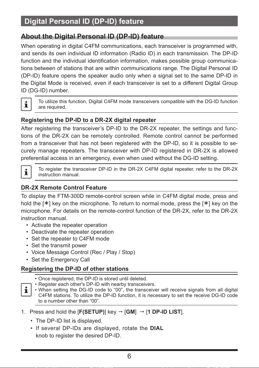
1. Press and hold the [F(SETUP)] key [GM] [1 DP-ID LIST].
• The DP-ID list is displayed.
• If several DP-IDs are displayed, rotate the DIAL
knob to register the desired DP-ID.
6
Page 7
2. A transmission in the digital C4FM mode from another
DG-ID: TX01 RX01
Station
each other's transceiver DP-ID on
their transceivers. However, they may
communicate because the same
DG-ID is set on both transceivers.
The transceivers may communicate
may receive station
has registered the
transceiver will register the DP-ID.
When a signal from the other station is received, the
call sign and “Registration” are displayed on the LCD.
DP-ID LIST
Registration
: YAESU
• When a signal from another registered transceiver is
received, nothing is displayed on the LCD.
• When a transceiver is previously registered with a
different call sign, the DP-ID listing is changed to the
newly registered call sign.
3. Press the DIAL knob to save the setting.
• When registering the DP-ID is complete, the display returns to the DP-ID list
screen.
• If not registering a DP-ID, rotate the DIAL knob to select “CANCEL” then press
the DIAL knob.
• If registering several DP-IDs, repeat step 2 and 3.
• A maximum of 24 stations may be registered.
4. Press the [DISP] key or the PTT, to save the setting and return to normal operation.
• All the other communicating stations should similarly register the DP-IDs to the
DP-ID lists of their transceivers.
• The DP-ID setting is complete.
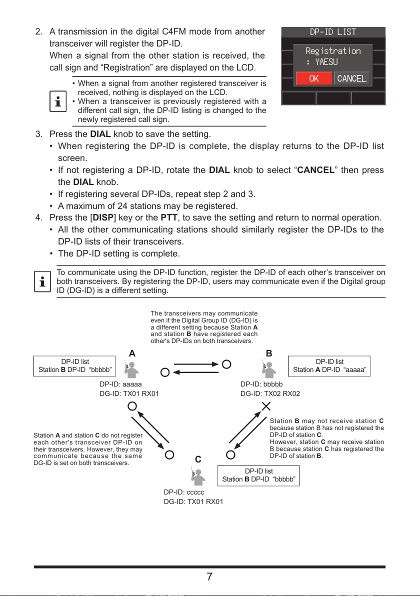
To communicate using the DP-ID function, register the DP-ID of each other’s transceiver on
both transceivers. By registering the DP-ID, users may communicate even if the Digital group
ID (DG-ID) is a different setting.
even if the Digital Group ID (DG-ID) is
a different setting because Station A
and station B have registered each
other's DP-IDs on both transceivers.
DP-ID list
Station B DP-ID “bbbbb”
A B
DP-ID: aaaaa
DG-ID: TX01 RX01
DP-ID list
Station A DP-ID “aaaaa”
DP-ID: bbbbb
DG-ID: TX02 RX02
A and station C do not register
DP-ID: ccccc
C
Station B DP-ID “bbbbb”
7
Station B may not receive station C
because station B has not registered the
DP-ID of station C.
However, station C
B because station C
DP-ID of station B.
DP-ID list
Page 8
Deleting a registered DP-ID
DP-ID LIST
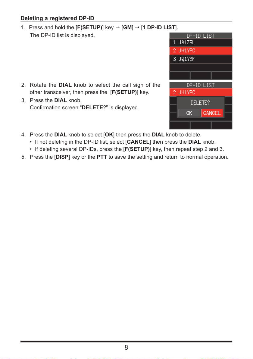
1. Press and hold the [F(SETUP)] key [GM] [1 DP-ID LIST].
The DP-ID list is displayed.
2. Rotate the DIAL knob to select the call sign of the
other transceiver, then press the [F(SETUP)] key.
3. Press the DIAL knob.
Confirmation screen “DELETE?” is displayed.
4. Press the DIAL knob to select [OK] then press the DIAL knob to delete.
• If not deleting in the DP-ID list, select [CANCEL] then press the DIAL knob.
• If deleting several DP-IDs, press the [F(SETUP)] key, then repeat step 2 and 3.
5. Press the [DISP] key or the PTT to save the setting and return to normal operation.
DP-ID LIST
1 JA1ZRL
2 JH1YPC
3 JQ1YBF
2 JH1YPC
: YAESU
DELETE?
8
Page 9
Communicating with specified stations in the Analog FM mode
Selecting the Squelch Type in the Analog FM Mode
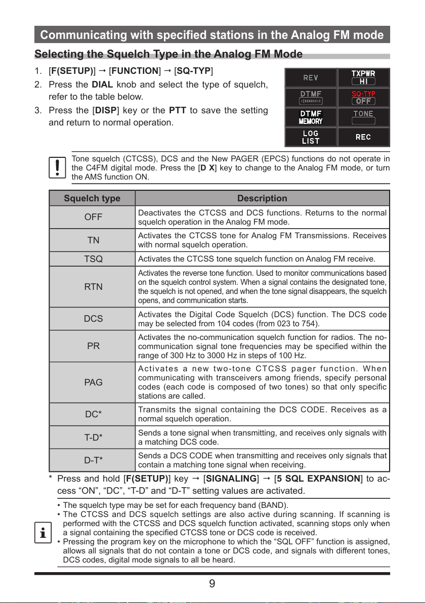
1. [F(SETUP)] [FUNCTION] [SQ-TYP]
2. Press the DIAL knob and select the type of squelch,
refer to the table below.
3. Press the [DISP] key or the PTT to save the setting
and return to normal operation.
Tone squelch (CTCSS), DCS and the New PAGER (EPCS) functions do not operate in
the C4FM digital mode. Press the [D X] key to change to the Analog FM mode, or turn
the AMS function ON.
Squelch type
OFF
TN
TSQ
RTN
DCS
PR
PAG
DC*
T-D*
D-T*
Deactivates the CTCSS and DCS functions. Returns to the normal
squelch operation in the Analog FM mode.
Activates the CTCSS tone for Analog FM Transmissions. Receives
with normal squelch operation.
Activates the CTCSS tone squelch function on Analog FM receive.
Activates the reverse tone function. Used to monitor communications based
on the squelch control system. When a signal contains the designated tone,
the squelch is not opened, and when the tone signal disappears, the squelch
opens, and communication starts.
Activates the Digital Code Squelch (DCS) function. The DCS code
may be selected from 104 codes (from 023 to 754).
Activates the no-communication squelch function for radios. The no-
communication signal tone frequencies may be specified within the
range of 300 Hz to 3000 Hz in steps of 100 Hz.
Activates a new two-tone CTCSS pager function. When
communicating with transceivers among friends, specify personal
codes (each code is composed of two tones) so that only specific
stations are called.
Transmits the signal containing the DCS CODE. Receives as a
normal squelch operation.
Sends a tone signal when transmitting, and receives only signals with
a matching DCS code.
Sends a DCS CODE when transmitting and receives only signals that
contain a matching tone signal when receiving.
Description
* Press and hold [F(SETUP)] key [SIGNALING] [5 SQL EXPANSION] to ac-
cess “ON”, “DC”, “T-D” and “D-T” setting values are activated.
• The squelch type may be set for each frequency band (BAND).
• The CTCSS and DCS squelch settings are also active during scanning. If scanning is
performed with the CTCSS and DCS squelch function activated, scanning stops only when
a signal containing the specified CTCSS tone or DCS code is received.
• Pressing the program key on the microphone to which the “SQL OFF” function is assigned,
allows all signals that do not contain a tone or DCS code, and signals with different tones,
DCS codes, digital mode signals to all be heard.
9
Page 10
Tone squelch feature
The tone squelch opens the speaker audio only when a signal containing the specified
CTCSS tone is received. The receiver will be quiet while waiting for a call from a specific
station.
The Tone Squelch does not function in digital mode. Press the [D X] key to change from
Digital, to Analog FM or to AMS function.
Setting CTCSS Tone frequency
The tone may be selected from 50 frequencies (67.0 Hz to 254.1 Hz).
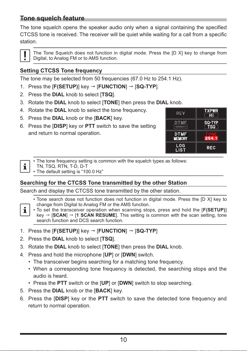
1. Press the [F(SETUP)] key [FUNCTION] [SQ-TYP].
2. Press the DIAL knob to select [TSQ].
3. Rotate the DIAL knob to select [TONE] then press the DIAL knob.
4. Rotate the DIAL knob to select the tone frequency.
5. Press the DIAL knob or the [BACK] key.
6. Press the [DISP] key or PTT switch to save the setting
and return to normal operation.
• The tone frequency setting is common with the squelch types as follows:
TN, TSQ, RTN, T-D, D-T
• The default setting is “100.0 Hz”
Searching for the CTCSS Tone transmitted by the other Station
Search and display the CTCSS tone transmitted by the other station.
• Tone search dose not function does not function in digital mode. Press the [D X] key to
change from Digital to Analog FM or the AMS function.
• To set the transceiver operation when scanning stops, press and hold the [F(SETUP)]
key [SCAN] [1 SCAN RESUME]. This setting is common with the scan setting, tone
search function and DCS search function.
1. Press the [F(SETUP)] key [FUNCTION] [SQ-TYP]
2. Press the DIAL knob to select [TSQ].
3. Rotate the DIAL knob to select [TONE] then press the DIAL knob.
4. Press and hold the microphone [UP] or [DWN] switch.
• The transceiver begins searching for a matching tone frequency.
• When a corresponding tone frequency is detected, the searching stops and the
audio is heard.
• Press the PTT switch or the [UP] or [DWN] switch to stop searching.
5. Press the DIAL knob or the [BACK] key.
6. Press the [DISP] key or the PTT switch to save the detected tone frequency and
return to normal operation.
10
Page 11
Digital Code Squelch (DCS) feature
The Digital Code Squelch opens the speaker audio only when a signal containing the
specified DCS code is received. The DCS code may be selected from 104 types (from
023 to 754).
The DCS Squelch does not function in digital mode. Press the [D X] key to change from
Digital to Analog FM or AMS mode.
Setting the DCS CODE
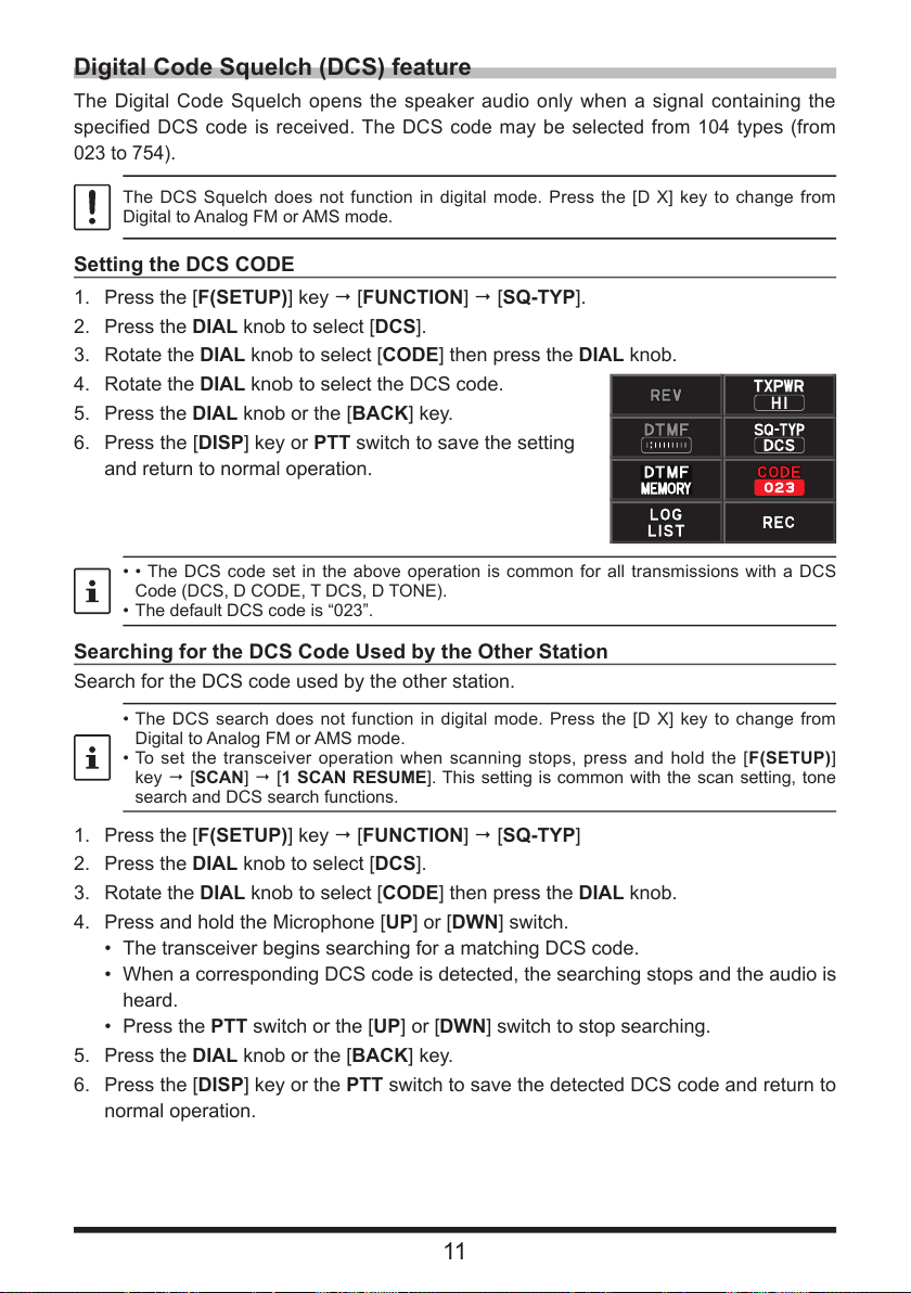
1. Press the [F(SETUP)] key [FUNCTION] [SQ-TYP].
2. Press the DIAL knob to select [DCS].
3. Rotate the DIAL knob to select [CODE] then press the DIAL knob.
4. Rotate the DIAL knob to select the DCS code.
5. Press the DIAL knob or the [BACK] key.
6. Press the [DISP] key or PTT switch to save the setting
and return to normal operation.
• • The DCS code set in the above operation is common for all transmissions with a DCS
Code (DCS, D CODE, T DCS, D TONE).
• The default DCS code is “023”.
Searching for the DCS Code Used by the Other Station
Search for the DCS code used by the other station.
• The DCS search does not function in digital mode. Press the [D X] key to change from
Digital to Analog FM or AMS mode.
• To set the transceiver operation when scanning stops, press and hold the [F(SETUP)]
key [SCAN] [1 SCAN RESUME]. This setting is common with the scan setting, tone
search and DCS search functions.
1. Press the [F(SETUP)] key [FUNCTION] [SQ-TYP]
2. Press the DIAL knob to select [DCS].
3. Rotate the DIAL knob to select [CODE] then press the DIAL knob.
4. Press and hold the Microphone [UP] or [DWN] switch.
• The transceiver begins searching for a matching DCS code.
• When a corresponding DCS code is detected, the searching stops and the audio is
heard.
• Press the PTT switch or the [UP] or [DWN] switch to stop searching.
5. Press the DIAL knob or the [BACK] key.
6. Press the [DISP] key or the PTT switch to save the detected DCS code and return to
normal operation.
11
Page 12
New Two-Tone CTCSS Pager Function
SIGNALING
When using FTM-300DR/DE transceivers with a group of friends, setting the Two-Tone
CTCSS personal codes allows calling just the specific stations. Even when the person
who is called is not near the transceiver, the information on the LCD indicates that a call
was received.
The new two-tone CTCSS pager feature does not operate in digital mode. Press the [D X]
key to change from Digital to Analog FM or the AMS function.
Using the Pager Function
1. Press the [F(SETUP)] key [FUNCTION] [SQ-TYP]
2. Press the DIAL knob to select [PAG ].
3. Press the [DISP] key or the PTT switch to save the setting and return to normal
operation.
Setting the Code for Your Station
Set the “pager code” to be called by other stations.
1. Activate the pager function (refer to “Using the pager function” above).
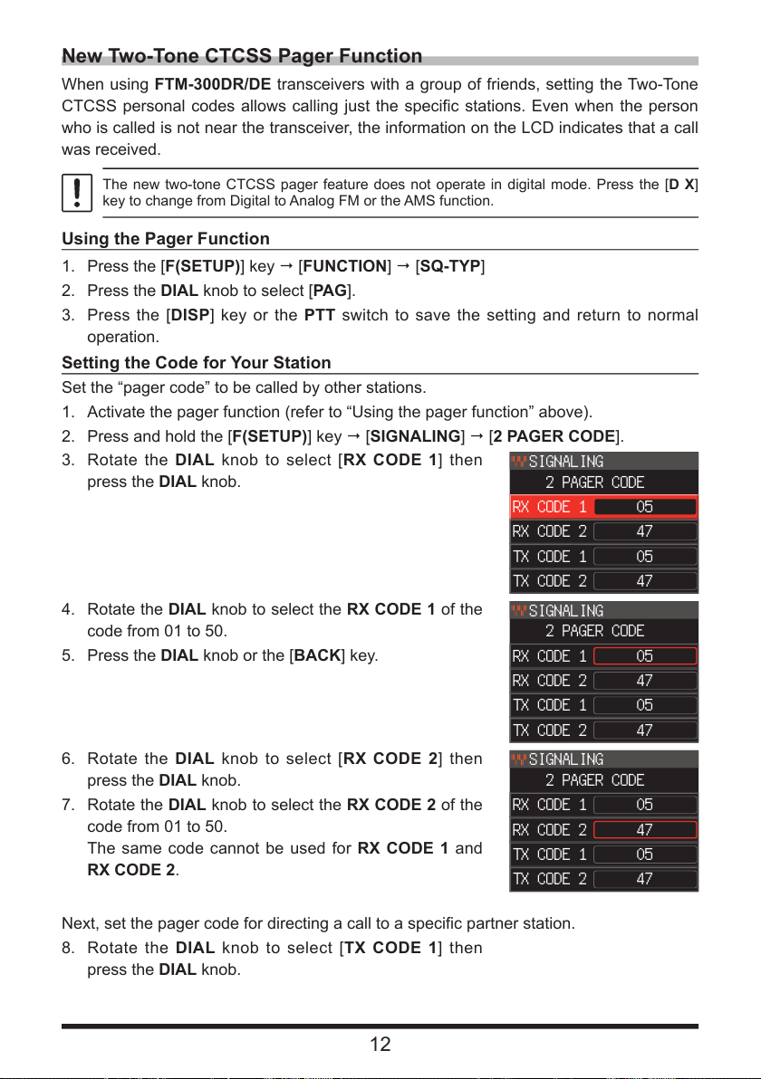
2. Press and hold the [F(SETUP)] key [SIGNALING] [2 PAGER CODE].
3. Rotate the DIAL knob to select [RX CODE 1] then
press the DIAL knob.
4. Rotate the DIAL knob to select the RX CODE 1 of the
code from 01 to 50.
5. Press the DIAL knob or the [BACK] key.
6. Rotate the DIAL knob to select [RX CODE 2] then
press the DIAL knob.
7. Rotate the DIAL knob to select the RX CODE 2 of the
code from 01 to 50.
The same code cannot be used for RX CODE 1 and
RX CODE 2.
SIGNALING
2 PAGER CODE
RX CODE 1
RX CODE 2
TX CODE 1
TX CODE 2
SIGNALING
2 PAGER CODE
RX CODE 1
RX CODE 2
TX CODE 1
TX CODE 2
2 PAGER CODE
RX CODE 1
RX CODE 2
TX CODE 1
TX CODE 2
05
47
05
47
05
47
05
47
05
47
05
47
Next, set the pager code for directing a call to a specific partner station.
8. Rotate the DIAL knob to select [TX CODE 1] then
press the DIAL knob.
12
Page 13
9. Rotate the DIAL knob to select the TX CODE 1 of the
SIGNALING
codes from 01 to 50.
10. Press the DIAL knob or the [BACK] key.
11. Rotate the DIAL knob to select [TX CODE 2] then
press the DIAL knob.
12. Rotate the DIAL knob to select the TX CODE 2 of the
codes from 01 to 50.
The same code cannot be used for TX CODE 1 and
TX CODE 2.
13. Press the [DISP] key or the PTT switch to save the
setting and return to normal operation.
14. Press the PTT switch to transmit a call to the specific
station.
• The reverse combination works as the same code, that is “05 47” is the same as “47 05”.
• If the same code is specified for all individuals, all the individuals can be called at the same
time.
• The default code is “05 47”.
• When receiving the codes, the sound of the tones may be heard intermittently.
Receiving “Pager Code” calls from a Remote Station (Standby Operation)
When the Pager function is activated, the audio of received calls with a corresponding
Pager Code is heard.
Furthermore, when the Bell function (see below) is activated, the bell rings when receiv-
ing calls from the other station.
Notification of a Call from a Remote Station by the Bell Function
The Bell may be set to sound an Alert when a call from another station containing a
cor-responding tone, DCS or pager code is received.
1. Press and hold the [F(SETUP)] key [SIGNALING] [4 BELL RINGER]
2. Rotate the DIAL knob to select the desired number of
times (1 - 8 times or continuous) the Bell rings.
1 time / 3 times / 5 times / 8 times / CONTINUOUS
If the setting is “CONTINUOUS”, the bell keeps
sounding until an operation is made.
1
2
3
4
OFF
AUTO DIALER
PAGER CODE >
PR FREQUENCY
BELL RINGER
3. Press the [DISP] key or the PTT switch to save the setting and return to normal
operation, The “
” icon appears on the display.
13
Page 14
Convenient memory function
Programmable Memory Channel Scan (PMS)
Registering to the Programmable Memory Channels
50 sets of PMS memory channels (L01/U01 to L50/U50) are available.
• Register the lower and upper frequencies of the frequency range in a pair of Program-
mable Memory Channels.
L nn: Lower limit memory channel
U nn: Upper limit memory channel
• PMS memory channels are displayed between channel 999 and channel 001. On the
memory channel list screen, turn the B-band DIAL knob to fast-forward in 10 channel
steps.
• For more details on registering frequencies to the memory channels, see “Writing to
Memory” in the Operating Manual.
• Make sure to use the corresponding numbers for the lower and upper limit memory
channels.
• Set the Programmable Memory scanning (PMS) lower and upper limits as follows:
• The scan width between the lower and upper limit frequencies must be 100 kHz or more.
• The lower and upper limit memory channels must be within the same frequency band.
• The lower and upper limit memory channels must not be registered in reverse.
Performing Programmable Memory Channel Scan
The programmable memory channel scan allows scanning a specified frequency range
within the same frequency band.
1. Press the [V/M(MW)] key to enter the memory mode.
2. Recall the PMS memory channel to which the lower limit (L nn) or upper limit (U nn)
of the frequency band is registered.
3. Press and hold the [UP] or [DWN] switch of the Microphone.
• Programmable memory channel scanning starts.
• Pressing the program key of the microphone set to the “SCAN” function also starts
the PMS scan operation.
• During scanning, “PMS” appears on the display.
• If the DIAL knob is rotated while scanning is in progress, the scanning will contin-
ue up or down in frequency according to the direction of the DIAL Knob rotation.
If the scanner halts on an incoming signal, the frequency will blink. Scanning will re-
sume in about five seconds.
4. Press the PTT switch or the [UP] or [DWN] switch of the microphone, to cancel the
scanning.
In this state (displayed as “PMS” at the upper left of the display), the frequency can
be changed only in the range stored by the lower and upper PMS memories, by turn-
ing the DIAL knob.
zDisable the PMS function
1. Press the [V/M] key.
Returns to the normal memory mode.
14
Page 15
Receiving Weather Broadcast Channels
This transceiver includes the preprogrammed VHF Weather Broadcast Station Memory
Channel Bank, and can receive the broadcast or the weather alert by recalling or scan-
ning a desired channel.
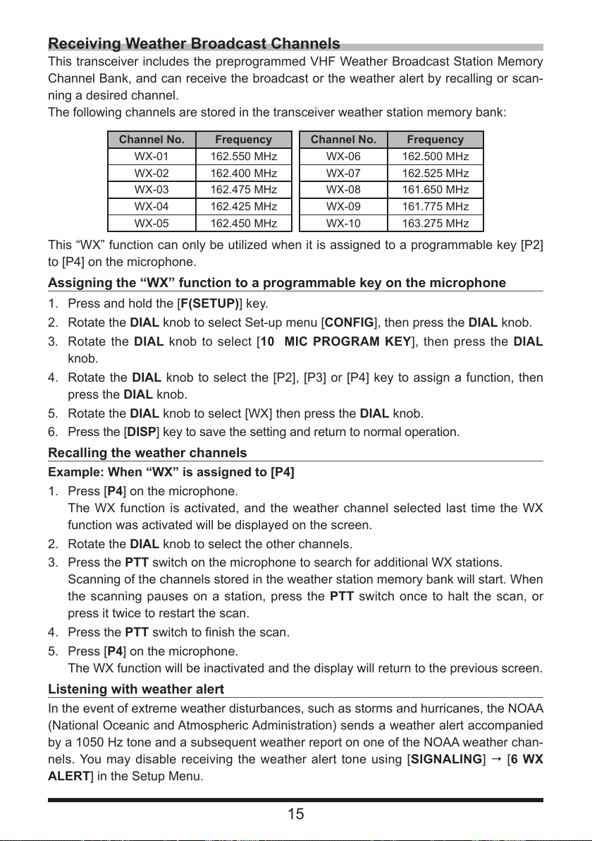
The following channels are stored in the transceiver weather station memory bank:
Channel No. Frequency Channel No. Frequency
WX-01 162.550 MHz WX-06 162.500 MHz
WX-02 162.400 MHz WX-07 162.525 MHz
WX-03 162.475 MHz WX-08 161.650 MHz
WX-04 162.425 MHz WX-09 161.775 MHz
WX-05 162.450 MHz WX-10 163.275 MHz
This “WX” function can only be utilized when it is assigned to a programmable key [P2]
to [P4] on the microphone.
Assigning the “WX” function to a programmable key on the microphone
1. Press and hold the [F(SETUP)] key.
2. Rotate the DIAL knob to select Set-up menu [CONFIG], then press the DIAL knob.
3. Rotate the DIAL knob to select [10 MIC PROGRAM KEY], then press the DIAL
knob.
4. Rotate the DIAL knob to select the [P2], [P3] or [P4] key to assign a function, then
press the DIAL knob.
5. Rotate the DIAL knob to select [WX] then press the DIAL knob.
6. Press the [DISP] key to save the setting and return to normal operation.
Recalling the weather channels
Example: When “WX” is assigned to [P4]
1. Press [P4] on the microphone.
The WX function is activated, and the weather channel selected last time the WX
function was activated will be displayed on the screen.
2. Rotate the DIAL knob to select the other channels.
3. Press the PTT switch on the microphone to search for additional WX stations.
Scanning of the channels stored in the weather station memory bank will start. When
the scanning pauses on a station, press the PTT switch once to halt the scan, or
press it twice to restart the scan.
4. Press the PTT switch to finish the scan.
5. Press [P4] on the microphone.
The WX function will be inactivated and the display will return to the previous screen.
Listening with weather alert
In the event of extreme weather disturbances, such as storms and hurricanes, the NOAA
(National Oceanic and Atmospheric Administration) sends a weather alert accompanied
by a 1050 Hz tone and a subsequent weather report on one of the NOAA weather chan-
nels. You may disable receiving the weather alert tone using [SIGNALING] [6 WX
ALERT] in the Setup Menu.
15
Page 16
DTMF Operation
DTMF (Dual Tone Multi Frequencies) are the tone signals sent to make telephone calls,
or control repeaters and network links. Up to 10 registers of 16-digit DTMF tone codes
can be stored as telephone numbers to make calls through the public telephone network
using a phone patch or to connect through the WIRES-X analog node station.
Setting the DTMF Memory
1. Press the [F(SETUP)] key [FUNCTION] [DTMF MEMORY]
2. Rotate the DIAL knob to select the desired channel (1 to 9) to register the DTMF
code, then press the DIAL knob.
The DTMF memory channel input screen is displayed.
3. Use the DIAL knob or numeric keypad of the microphone to input the DTMF code up
to a maximum of 16 digits.
4. Press the DIAL knob, then press the [DISP] key to save the setting and return to
normal operation.
Transmitting the Registered DTMF Code
Use the auto dialer function to automatically transmit the DTMF code registered in the
DTMF memory.
1. Press and hold the [F(SETUP)] key [SIGNALING] [1 AUTO DIALER]
2. Press the DIAL knob to select “ON”.
3. Press the [DISP] key or the PTT switch, to save the setting and return to normal
operation.
When set to “ON”, the DTMF icon “
Transmitting DTMF code automatically using DTMF memory
1. Set the DTMF code “ON” by referring to “Transmitting the Registered DTMF Code”
(above).
2. Press the [F(SETUP)] key [FUNCTION] [DTMF]
3. Press the DIAL knob.
4. Rotate the DIAL knob to select the desired channel (1 to 9).
5. Press the PTT switch.
• The DTMF code registered in the DTMF memory channel is automatically trans-
mitted.
• Even after releasing the PTT switch, the transmission continues until the DTMF
code is completed. The transceiver is automatically returned to receive mode.
6. Press the [DISP] key or the PTT switch to restore normal operation.
Manually Transmitting the DTMF Code
1. While pressing and holding the PTT switch, use the numeric keypad of the micro-
phone and press each digit of the DTMF code in sequence to transmit the code.
” will be shown on the display.
The DTMF code can be sent manually regardless of whether the auto dialer is set to ON or
OFF.
16
Page 17
Using the GPS Function
The transceiver is equipped with an internal GPS receiver to acquire and display the
position information. The GPS information can be used as described in the following
examples:
Display the location information of the partner station in digital mode
Refer to “Real-Time Navigation Function” (Page 18)
Save the position information in the memory and use it for navigation purposes
Refer to “Backtrack Function” (Page 18)
Save your location information and display the trajectory on your computer
Refer to “Saving GPS Information (GPS Log Function)” (Page 20)
Save the DP-ID of frequently contacted stations and check whether they are
within the sphere of communications
Refer to the separate “Operating Manual GM Edition”
Exchange position information and messages through data communications
with other stations
Refer to the separate “Operating Manual APRS Edition”
Positioning Using GPS
The built-in GPS receiver function is enabled when the power of the FTM-300DR/DE
is turned ON. The satellite search will begin and the “
of the display. The FTM-300DR/DE automatically obtains the internal clock setting, and
your location information setting from the GPS data.
• It may take several minutes to acquire the GPS satellites.
• When three or more satellites cannot be acquired, the “ ” icon will disappear. In this
case, positioning is not possible, and the position information cannot be used.
” icon will be shown at the top
About Positioning by GPS
“Positioning” refers to calculation of your current position from the satellite orbit infor-
mation and radio propagation time. At least 3 satellites must be acquired for successful
positioning. If positioning fails, move away from buildings as far as possible and posi-
tion the GPS receiver in an area with open sky.
zAbout errors
The measurement environment may result in positioning errors of several hundred
meters. Under favorable conditions, positioning can be performed successfully using
only three satellites. However, under the following poor conditions, the positioning
accuracy can decrease, or positioning can fail:
• Between tall buildings
• Narrow paths between buildings
• Indoors or near large buildings
• Between trees such as in forests or woods
• Under elevated roads or high voltage power lines
• Inside a tunnel or underground
• Through heat reflective glass
• Areas with strong magnetic fields
zWhen not in use for a long time
When using the GPS functions for the first time after purchase, or when it has
been unused in a while, a few minutes may be required to acquire the satellites.
Also, if the GPS function has been turned OFF for several hours, a few minutes
may be required to search for satellites.
17
Page 18
Smart Navigation Function
GPS position information and voice signals are simultaneously transmitted in the V/D
mode of C4FM digital. Consequently, the position and direction of the remote station can
be displayed in real time, even while communicating.
To use the “latitude/longitude display” with the smart navigation function, press and hold
the [F(SETUP)] key [DISPLAY] [1 TARGET LOCATION] and set to “NUMERIC
factory setting is “COMPASS”)
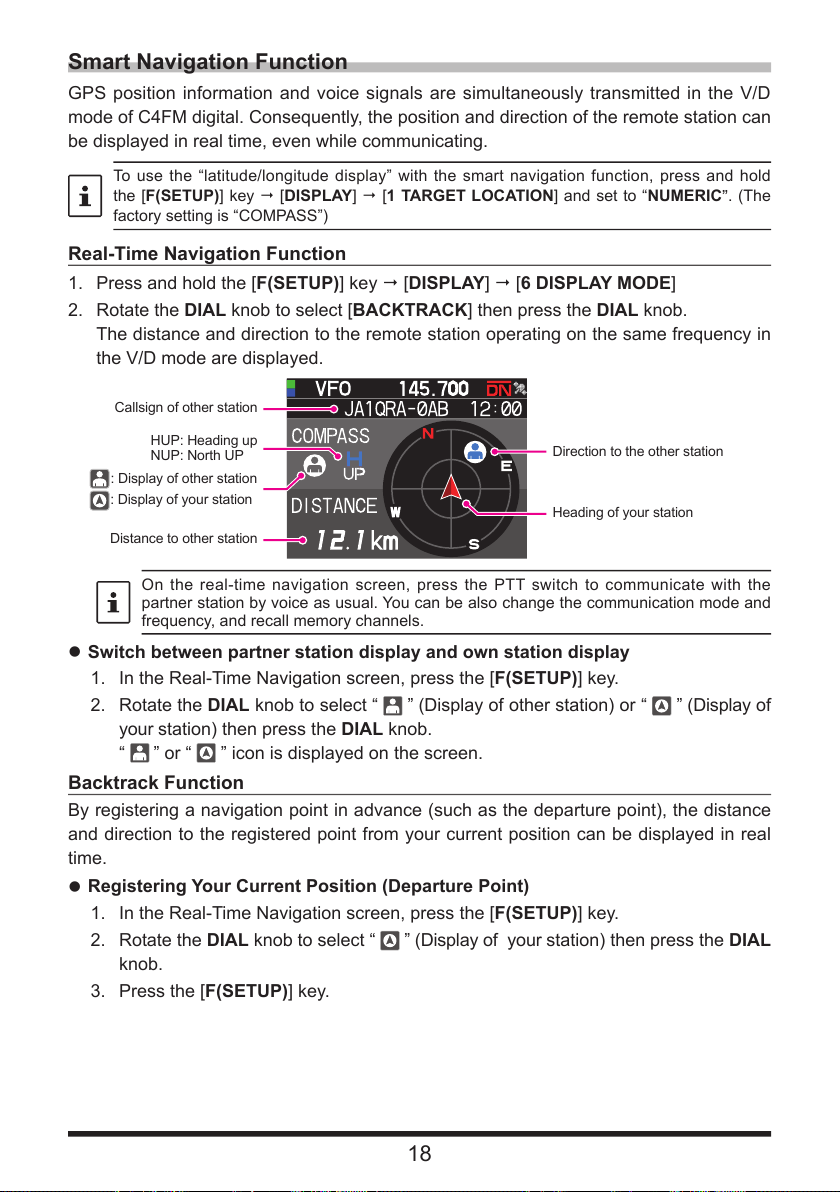
Real-Time Navigation Function
1. Press and hold the [F(SETUP)] key [DISPLAY] [6 DISPLAY MODE]
2. Rotate the DIAL knob to select [BACKTRACK] then press the DIAL knob.
The distance and direction to the remote station operating on the same frequency in
the V/D mode are displayed.
Callsign of other station
HUP: Heading up
NUP: North UP
: Display of other station
: Display of your station
Distance to other station
On the real-time navigation screen, press the PTT switch to communicate with the
partner station by voice as usual. You can be also change the communication mode and
frequency, and recall memory channels.
Direction to the other station
Heading of your station
zSwitch between partner station display and own station display
1. In the Real-Time Navigation screen, press the [F(SETUP)] key.
2. Rotate the DIAL knob to select “
your station) then press the DIAL knob.
“
” or “
” icon is displayed on the screen.
” (Display of other station) or “ ” (Display of
Backtrack Function
By registering a navigation point in advance (such as the departure point), the distance
and direction to the registered point from your current position can be displayed in real
time.
zRegistering Your Current Position (Departure Point)
1. In the Real-Time Navigation screen, press the [F(SETUP)] key.
2. Rotate the DIAL knob to select “
” (Display of your station) then press the DIAL
knob.
3. Press the [F(SETUP)] key.
. (The
”
18
Page 19
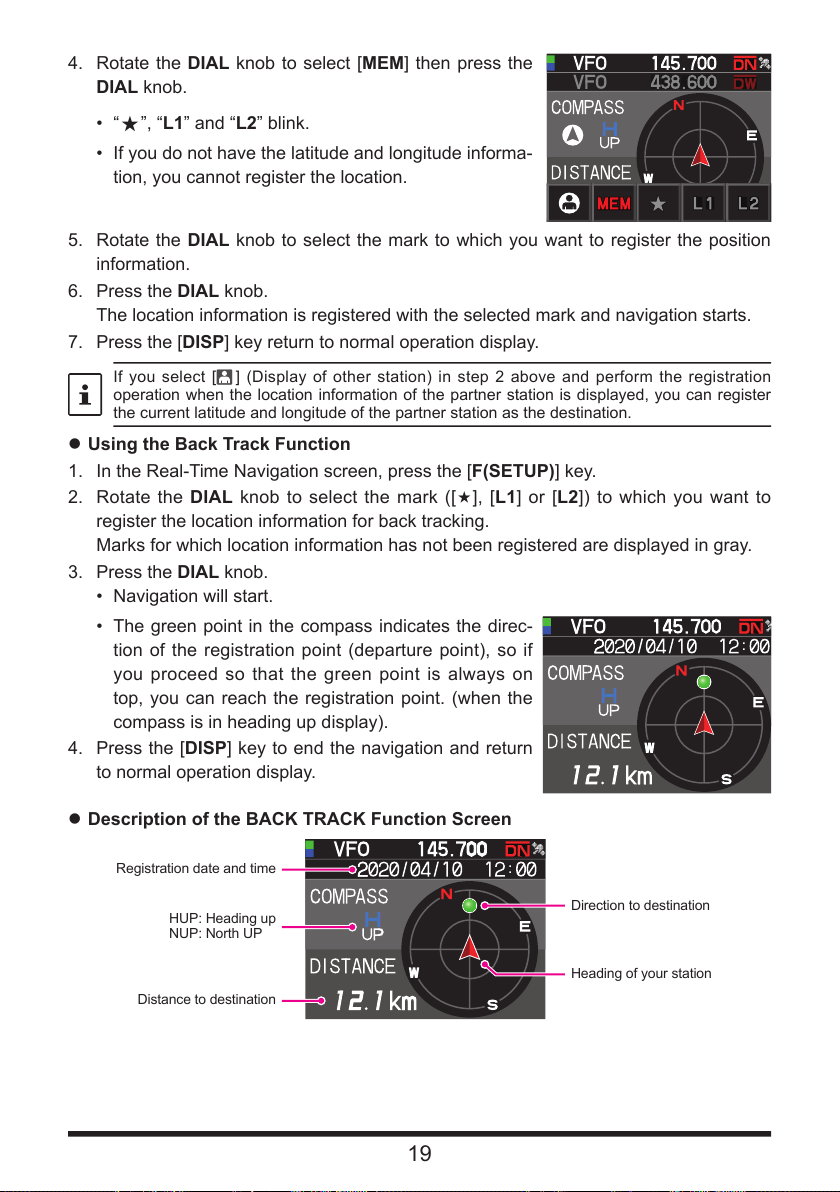
4. Rotate the DIAL knob to select [MEM] then press the
DIAL knob.
• “
”, “L1” and “L2” blink.
«
• If you do not have the latitude and longitude informa-
tion, you cannot register the location.
5. Rotate the DIAL knob to select the mark to which you want to register the position
information.
6. Press the DIAL knob.
The location information is registered with the selected mark and navigation starts.
7. Press the [DISP] key return to normal operation display.
If you select [ ] (Display of other station) in step 2 above and perform the registration
operation when the location information of the partner station is displayed, you can register
the current latitude and longitude of the partner station as the destination.
zUsing the Back Track Function
1. In the Real-Time Navigation screen, press the [F(SETUP)] key.
2. Rotate the DIAL knob to select the mark ([«], [L1] or [L2]) to which you want to
register the location information for back tracking.
Marks for which location information has not been registered are displayed in gray.
3. Press the DIAL knob.
• Navigation will start.
• The green point in the compass indicates the direc-
tion of the registration point (departure point), so if
you proceed so that the green point is always on
top, you can reach the registration point. (when the
compass is in heading up display).
4. Press the [DISP] key to end the navigation and return
to normal operation display.
zDescription of the BACK TRACK Function Screen
Registration date and time
HUP: Heading up
NUP: North UP
Distance to destination
19
Direction to destination
Heading of your station
Page 20
zChanging the direction of the compass panel
The compass panel can be set to “HEADING UP” where the direction of your travel is
always displayed at the top, or “NORTH UP” where North is always displayed at the top.
1. Press and hold the [F(SETUP)] key [DISPLAY] [2 COMPASS]
2. Press the DIAL knob to select [HEADING UP] or [NORTH UP].
3. Press the [DISP] key to save the setting and return to normal operation display.
Saving GPS Information (GPS Log Function)
The GPS position information can automatically be saved periodically onto a microSD
memory card. Using the saved data, tracks can be displayed on commercially available
map software*.
* Technical support for the map software is not provided by YAESU.
1. Press and hold the [F(SETUP)] key [CONFIG] [17 GPS LOG]
2. Rotate the DIAL knob to select the GPS data logging interval.
OFF / 1 sec / 2 sec / 5 sec / 10 sec / 30 sec / 60 sec
3. Press the [DISP] key or the PTT switch to save the setting and return to the normal
operation display.
The GPS log function is activated, and GPS log “
• The position information is saved periodically unless “OFF” is selected in step 2 (shown
above) or the power of the transceiver is turned OFF.
• Reselecting the GPS data logging interval in step 2 or turning on the transceiver again,
begins saving the GPS data under a different file name.
• To use the GPS log function, a commercially available micro SD card must be inserted in the
FTM-300DR/DE. For details, refer to the Operating Manual.
Checking Tracks on Your PC
1. Turn the transceiver OFF.
2. Remove the microSD memory card from the transceiver.
3. Connect the microSD memory card to your PC using a commercially available
memory card reader.
4. Open the “FTM300D” folder in the microSD memory card.
5. Open the “GPSLOG” folder.
• The data is saved as “GPSyymmddhhmmss.log”
• The [yymmddhhmmss] part of the name consists of year (yy), month (mm), day (dd),
hour (hh), minute (mm), and second (ss).
” icon will be displayed.
• Tracks can be displayed on the map by importing the data to commercially available map
software.
• For information on importing, please refer to the operation manual for the map software you
use.
20
Page 21

GPS Screen Information and Operation
Activating the GPS function presents the following information on the display.
1. Press and hold the [F(SETUP)]key [DISPLAY] [6 DISPLAY MODE]
2. Rotate the DIAL knob to select [GPS INFORMATION] then press the DIAL knob.
Azimuth and elevation
③
of satellite
Latitude and longitude
①
of the current location
Time
②
Displays the latitude and longitude
Latitude (upper side)
Display format: X DD°MM.MMM'
X: X=N: North latitude, X=S: South latitude, DD: Degree, MM:MMM Minute
Example: N 35°38.250 (35 degrees, 38 minutes, 15 seconds north latitude)
Longitude (lower side)
Display format: X DDD°MM.MMM'
X: X=E: East longitude, X=W: West longitude, DDD: Degree, MM:MMM Minute
Example: E 139°42.500 (139 degrees, 42 minutes, 30 seconds east longitude)
Current time (24-hour display)
Displays the satellite azimuth and elevation angles. Displays in North-up mode.
Receiving satellites are displayed in blue.
• When the GPS function is used, the accurate time and date are obtained from GPS and
shown on the LCD in 24-hour format. This time data is displayed on the GPS and APRS
screens.
• The geodetic system datum (WGS-84 / TOKYO MEAN) of the built-in GPS unit may be
changed by pressing and holding the [F(SETUP)] key [CONFIG] [15 GPS DATUM] in
Set mode. However, since APRS uses the WGS-84 geodetic system, it is recommended
not to change it.
• The time zone may be set at 30-minute increments by pressing and holding the [F(SETUP)]
key [CONFIG] [3 TIME ZONE] (the default setting: UTC 0:00).
• The position information obtained from an externally connected GPS device may be used
by pressing and holding the [F(SETUP)] key [CONFIG] [16 GPS DEVICE] and then
setting “EXTERNAL”. In this case, the data from the internal GPS will be ignored.
• When using an external GPS device, move it away from the transceiver to reduce
interference.
21
Page 22

Measuring the altitude
The changes in the altitude of the current position and the distance travelled can be dis-
played on a graph.
1. Press and hold the [F(SETUP)] key [DISPLAY]
[6 DISPLAY MODE].
2. Rotate the DIAL knob to select [ALTITUDE] then press
the DIAL knob.
The altitude screen is displayed.
zChanging the altitude scale
1. In the Altitude scale screen, press the [F(SETUP)] key.
2. Rotate the DIAL knob to select [SCALE].
3. Press the DIAL knob, the scale value will change in the following order.
5km / 20km / 40km / 80km
The maximum altitude scale will be automatically set based on the present altitude values.
zErasing the previous altitude changes
1. In the Altitude scale screen, press the [F(SETUP)] key.
2. Rotate the DIAL knob to select [CLEAR] then press the DIAL knob.
The graph (history) is deleted.
22
Page 23

Functions used as needed
Timer / Clock function
1. Press and hold [F(SETUP)] key [DISPLAY] [6 DISPLAY MODE]
2. Rotate the DIAL knob to select [TIMER/CLOCK] then press the DIAL knob.
The Clock screen will be displayed.
3. The following functions can be selected each time the DIAL knob is pressed after
pressing the [F (SETUP)] key.
Clock screen / Lap timer screen / Countdown timer screen
4. Press the [BACK] key twice, return to the normal operation display.
Using the lap timer
1. Press the [F(SETUP)] key.
2. Rotate the DIAL knob to select [MODE] then press
the DIAL knob several times to display the lap timer
screen.
zStart measurement
1. Rotate the DIAL knob to select [START] then press the
DIAL knob.
The timer will start.
zMeasure lap time
1. Rotate the DIAL knob during measurement and select
[LAP].
2. Each time press the DIAL knob, the lap time is stored.
Up to 99 lap times can be saved in the memory.
zCall lap time
1. Rotate the DIAL knob to select [RECALL] then press the DIAL knob.
The lap time and split time are displayed.
2. When there are multiple lap times, rotate the DIAL knob to select [p] or [q] then
press the DIAL knob to switch between the lap times.
zStop measurement
1. Rotate the DIAL knob to select [STOP] then press the DIAL knob.
The timer will stop.
zClear the measurement result
1. When measurement is stopped, turn the DIAL knob to select [RESET] then press
the DIAL knob.
All measurement results will be erased.
23
Page 24

Using the countdown timer
1. Press the [F(SETUP)] key.
2. Rotate the DIAL knob to select [MODE] then
press the DIAL knob several times to display the
countdown timer screen.
zSet the timer
1. Rotate the DIAL knob to select [SETUP] then press
the DIAL knob.
The countdown timer setting screen will be dis-
played.
The factory default is 15 minutes.
2. Rotate the DIAL knob to select [-] or [+] then press
the DIAL knob to set the hour.
The hour can be set between 00 and 99.
3. Rotate the DIAL knob to select [SETUP] then press
the DIAL knob.
4. Rotate the DIAL knob to select [-] or [+] then press
the DIAL knob to set the minute.
The minute can be set between 00 and 59.
5. Rotate the DIAL knob to select [SETUP] then press
the DIAL knob.
zStart the timer
1. Rotate the DIAL knob to select [START] then press the DIAL knob.
• The countdown timer will start.
• When the set time has elapsed, a beep will sound.
zStop the timer
1. Rotate the DIAL knob to select [STOP] then press the DIAL knob.
• To restart, turn the DIAL knob to select [START] then press the DIAL knob.
• To reset the timer to the set value, turn the DIAL knob to select [RESET] then
press the DIAL knob.
24
Page 25

Using the Voice Guide unit FVS-2
The receive audio can be recorded and then played back later using the optional voice
guide unit “FVS-2”. The frequency of the operating band can also be announced by
voice when the announce function is set to ON.
Mounting the voice guide unit “FVS-2”
zPreparations
• Voice guide unit “FVS-2” (optional)
• Plus driver
zMounting procedure
• Avoid touching the electronic components with your hands as the semiconductors may be
damaged by static electricity.
• Note that labor charges to install optional items by our customer service support staff shall
be separately chargeable.
1. Turn the transceiver OFF.
2. Turn the external power supply OFF.
3. Unplug the control cable, microphone, and DC power supply cables from the main
chassis.
4. Remove the eight screws from the main body, four on
top and two each at the sides.
: Please note that the 2 screws on the front panel side
of the top cover are longer than the other 6 screws.
5. Carefully lift the top cover of the main body.
Do not lift the top cover by force. This may result in
cables connected between the circuit boards and the
speaker inside the cover to be cut.
Speaker Cable
6. Unplug the speaker cables extending from the top cover from the socket on the
board inside the main body before removing the cover.
Hold the connector when unplugging the cable without pulling on the cable itself.
25
Page 26

7. Refer to the figure on the right to mount the FVS-2.
Check the direction of the connector and plug the
FVS-2 in all the way to the back.
8. Plug in the speaker cables extending from the main
body top cover to the original connector on the board.
9. Attach the main body top cover and secure it using
the eight screws.
Speaker Connector
FVS-2 Connector
Using the voice memory
The voice memory permits recording the received audio in the optional FVS-2 that is
mounted inside the radio. The saved audio can be replayed on the radio and erased lat-
er.
Setting the voice memory operation
1. Press and hold the [F(SETUP)] key [OPTION] [3 VOICE MEMORY]
• The screen for the detailed settings will be displayed.
• Cannot be selected when the optional FVS-2 is not installed.
2. Rotate the DIAL knob to select [PLAY/REC].
3. Each time press the DIAL knob, the recording operation switches.
FREE 5min: A total of 5 minutes of audio in 8 recording areas can be recorded.
LAST 30sec: The last 30 seconds will be recorded.
Factory default value: FREE 5min
4. Press the [DISP] key or the PTT switch to save the setting and return to the normal
operation display.
26
Page 27

Recording the receive audio
1. Press the [F(SETUP)] key [FVS-2]
2. Rotate the DIAL knob to select [M.REC], then press the DIAL knob.
The recording will be started.
3. Rotate the DIAL knob to select [STOP], then press the DIAL knob.
• The recording will stop.
• The track number of the recorded audio will be displayed “PLAY TRACK”.
4. Press the [DISP] key or the PTT switch to return to normal operation display.
Replaying the recorded audio
1. Press the [F(SETUP)] key [FVS-2]
2. Rotate the DIAL knob to select [TRACK], then press the DIAL knob to select the
track number to be replayed.
• When there are two or more recordings, the track number will change in the order
“ALL”, “1”, “2”… each time the DIAL knob is pressed.
• When “ALL” is selected, all the recorded tracks will be replayed in sequence.
3. Rotate the DIAL knob to select [PLAY], then press the DIAL knob.
• Replay will be started.
• Replay will stop automatically at the end of the selected track.
4. Rotate the DIAL knob to select [STOP], then press the DIAL knob to stop the replay.
5. Press the [DISP] key or the PTT switch return to normal operation display.
Erasing the recorded audio
1. Press the [F(SETUP)] key [FVS-2]
2. Rotate the DIAL knob to select [CLEAR], then press the DIAL knob.
The confirmation screen will be displayed.
3. Rotate the DIAL knob to select [OK], then press the DIAL knob.
A beep will sound, and erasing will be started.
• • All recorded audio will be erased. When there are two or more recordings, individual
tracks cannot be erased.
• It takes about 10 seconds to erase.
When erasing is complete, “M.REC” will be selected.
4. Press the [DISP] key or the PTT switch return to normal operation display.
27
Page 28

Voice announcement of the operating frequency
Setting the announce function operation
Set the following voice announcement parameters:
• Automatically announce the frequency or not
• Announce out the frequency in English or Japanese
• Voice announcement audio level
• Mute the receive audio during a voice announcement.
1. Press and hold the [F(SETUP)] key [OPTION] [3 VOICE MEMORY]
2. Rotate the DIAL knob to select [ANNOUNCE].
3. Press the DIAL knob to select the condition for reading out of the frequency.
The setting will switch between “AUTO”, “OFF” and “MANUAL” each time the DIAL
knob is pressed.
OFF: The frequency is not announced.
AUTO: The frequency is announced when changing bands, switching between
VFO mode and Memory mode, or announced the [F(SETUP)] key
[FVS-2] [VOICE GUIDE].
MANUAL: announced [F(SETUP)] key [FVS-2] [VOICE GUIDE].
Factory default value: AUTO
4. Rotate the DIAL knob to select [LANGUAGE].
5. Press the DIAL knob to select the language in which the frequency is announced.
The setting will switch between “ENGLISH” and “JAPANESE” each time the DIAL
knob is pressed.
Factory default value: ENGLISH
6. Rotate the DIAL knob to select [VOLUME].
7. Press the DIAL knob to select the announcement volume.
The setting will switch between “HIGH”, “MID” and “LOW” each time the DIAL knob
is pressed.
Factory default value: HIGH
8. Rotate the DIAL knob to select [RX MUTE].
9. Press the DIAL knob to select ON/OFF.
The setting will switch between “ON” and “OFF” each time it is pressed.
ON: The receive audio will be muted during a voice announcement or replaying re-
corded audio.
OFF: The receive audio will not be muted during a voice announcement or replaying
recorded audio.
Factory default value: ON
28
Page 29

Voice announcement of the operating frequency
(1) When the voice announcement is set to
The frequency of the operating band will be automatically announced in the following
cases:
• When the VFO mode and memory mode are switched.
• When the operating band is changed.
• The frequency will also be announced when pressing the [F(SETUP)] key [FVS-2]
[VOICE GUIDE].
• The volume announcement voice is linked to the volume of the operation band.
(2) When the voice announcement is set to “MANUAL”
1. Press the [F(SETUP)] key [FVS-2]
2. Rotate the DIAL knob to select [VOICE GUIDE], then press the DIAL knob.
The frequency of the operating band will be announced.
The volume of the announcement voice is linked to the volume of the operation band.
29
Page 30

Copying the Radio Data to another Transceiver
The memory channels and settings in the set-up menu can be copied to another FTM-
300DR/DE. This is convenient when matching the settings of fellow stations that you
communicate with frequently.
1. Turn both transceivers OFF.
2. Connect the optional clone cable “CT-166” to the DATA
jack on the back of the main bodies.
3. Turn both transceivers ON.
4. Press and hold the [F(SETUP)] key [CLONE]
5. On the transceiver from which data is to be copied,
rotate the DIAL knob to select [1 This Other], then
press the DIAL knob.
The confirmation screen appears.
6. On the transceiver to which data is to be copied, rotate
the DIAL knob to select [2 Other This], then press
the DIAL knob.
The confirmation screen appears.
7. On the transceiver to which data is to be copied, rotate the DIAL knob to select [OK],
then press the DIAL knob.
8. On the transceiver from which data is to be copied, rotate the DIAL knob to select
[OK], then press the DIAL knob.
The data transfer begins.
When data transfer is complete, “Completed” appears.
9. Press the [DISP] key or the PTT switch return to normal operation display.
10. Turn both transceivers OFF, then disconnect the clone cable.
• When “ERROR” appears on the screen during the clone operation, the operation has not
completed. Check the clone cable connection, and then repeat the procedure from the
beginning.
• If the clone operation is terminated due to a power loss during the data transfer, the
transceiver to which the data is copied will be reset automatically. Check the power supply,
cables and connections, then repeat the procedure again from the beginning.
CLONE
1 This → Other
2 Other → This
CLONE
1 This → Other
2 Other → This
30
Page 31

Connecting an external device
DATA jack
To the personal computer
Using the optional Data cable, the transceiver can be connected to a personal computer
as a COM port for the following operations:
• Transfer GPS location data and export route mapping information to computer soft-
ware
• Packet communication
Use the DATA jack at the back of the main body to connect with the personal computer.
The pin assignment of the DATA jack is as follows.
Connecting to a computer
zPreparation
• Computer
• PC connection cable “SCU-20” (Included in optional SCU-40)…When connecting to
the USB jack of the computer.
PKD (packet data input)
GND
PSK(PTT
RX 9600 (9600 bps packet data output)
RX 1200 (1200 bps packet data output)
PK SQL (squelch control)
TXD (serial data output [transceiver PC])
RXD (serial data input [transceiver ! PC])
CTS (data communication control)
RTS (data communication control)
)
To the transceiver
(USB terminal)
• Data cable “CT-165” (optional)…When connecting to the RS-232C jack of the computer.
To the transceiver To the personal computer
-
GND
-
-
-
-
TXD (serial data output [transceiver PC])
RXD (serial data input [transceiver ! PC])
CTS (data communication control)
RTS (data communication control)
• Make sure to turn the transceiver OFF before connecting any cables.
• When using the SCU-20 PC connection cable, install the designated driver on the
computer. Download the driver and installation manual from the Yaesu website.
-
TXD (serial data output [transceiver PC])
RXD (serial data input (transceiver ! PC])
-
GND
-
CTS (data communication control)
RTS (data communication control)
-
31
Page 32

Transmitting GPS location information
The GPS position data (latitude/longitude) of your own station can be output from the
serial DATA jack on the rear of the transceiver.
1. Press and hold the [F(SETUP)] key [DATA] [1 COM PORT SETTING]
2. Rotate the DIAL knob to select [OUTPUT].
3. Press the DIAL knob to set “GPS OUT”.
The setting changes in the following order:
OFF GPS OUT PACKET WAYPOINT
Factory default value: OFF
4. Rotate the DIAL knob to select [SPEED], then press the DIAL knob.
5. Rotate the DIAL knob to select the desired communication speed.
The setting changes in the following order:
4800bps 9600bps 19200bps 38400bps 57600bps
Factory default value: 9600bps
6. Press the [DISP] key or the PTT switch to save the setting and return to the normal
operation display.
Transmits the location information data. The location data is output to the computer
at about one second intervals.
An operating software using NMEA-0183 standard GGA and RMC sentence is required to
use the position information.
Updating the transceiver firmware
When updated firmware is available, the transceiver can be updated by connecting it to
a personal computer. Download the latest version of the firmware and the firmware in-
stallation manual from the YAESU website.
32
Page 33

Using the transceiver for packet communications
A TNC (Terminal Node Controller) may be connected to the transceiver to enable packet
communications.
zPreparation
• TNC
• Computer
• Data cable*...Prepare a cable suitable for the connected device.
*The following optional products are available.
• Data cable “CT-164”(optional)
To the transceiver To the TNC etc.
PKD (packet data input)
GND
PSK(PTT
RX 9600 (9600 bps packet data output)
RX 1200 (1200 bps packet data output)
PK SQL (squelch control)
-
-
-
-
)
• Data cable “CT-163”(optional)
To the transceiver
PKD (packet data input)
GND
PSK(PTT
RX 9600 (9600 bps packet data output)
RX 1200 (1200 bps packet data output)
PK SQL (squelch control)
TXD (serial data output [transceiver PC])
RXD (serial data input [transceiver ! PC])
CTS (data communication control)
RTS (data communication control)
)
PKD (packet data input)
GND
PSK(PTT
RX 9600 (9600 bps packet data output)
RX 1200 (1200 bps packet data output)
PK SQL (squelch control)
To the personal computer etc.
Dsub 9 pin
-
TXD (serial data output [transceiver PC])
RXD (serial data input [transceiver ! PC])
-
GND
-
CTS (data communication control)
RTS (data communication control)
-
DIN 6 pin
PKD (packet data input)
GND
PSK(PTT
RX 9600 (9600 bps packet data output)
RX 1200 (1200 bps packet data output)
PK SQL (squelch control)
)
To the TNC etc.
)
33
Page 34

• Data cable “CT-167”(optional)
To the TNC etc.
To the transceiver
PKD (packet data input)
GND
PSK(PTT
RX 9600 (9600 bps packet data output)
RX 1200 (1200 bps packet data output)
PK SQL (squelch control)
TXD (
RXD (serial data input [transceiver ! PC])
CTS (data communication control)
RTS (data communication control)
)
serial data output [transceiver
• Make sure to turn the power to the radio OFF before connecting.
• Refer to the TNC operating manual for instruction on connecting the TNC to a personal
computer.
• RF receive interference may occur because of noise occurring in the personal computer.
When signals cannot be received normally, keep the personal computer at a distance away
from the radio and use a photo-coupler and noise filter to connect.
PC])
Brown PKD (packet data input)
Black thick wire GND
Red PSK (PTT)
Orange
RX 9600 (9600 bps packet data output)
Yellow RX 1200 (1200 bps packet data output)
Green PK SQL (squelch control)
Blue TXD (
Grey RXD (
White CTS (data communication control)
Black RTS (data communication control)
serial data output [transceiver
serial data input [transceiver
PC])
! PC])
zPacket communication settings
1. Press and hold the [F(SETUP)] key [DATA] [1 COM PORT SETTING]
2. Rotate the DIAL knob to select [OUTPUT].
3. Press the DIAL knob to set “PACKET”.
The setting changes in the following order:
OFF GPS OUT PACKET WAYPOINT
Factory default value: OFF
4. Rotate the DIAL knob to select [SPEED], then press the DIAL knob.
5. Rotate the DIAL knob to select the desired communication speed.
The setting changes in the following order:
4800bps 9600bps 19200bps 38400bps 57600bps
Factory default value: 9600bps
6. Press the [BACK] key twice.
7. Rotate the DIAL knob to select [2 DATA BAND SELECT], then press the DIAL knob.
8. Rotate the DIAL knob to select [DATA], then press the DIAL knob.
9. Rotate the DIAL knob to select the band to be used for the packet communication.
The setting changes in the following order:
MAIN BAND SUB BAND A-BAND FIX B-BAND FIX A=TX/B=RX
A=RX/B=TX
• Refer to “Sets the APRS and data communication operating band” (page 56) for
details.
Factory default value: B-BAND FIX
•
10. Press the [BACK] key twice.
34
Page 35

11. Rotate the DIAL knob to select [3 DATA SPEED], then press the DIAL knob.
12. Rotate the DIAL knob to select [DATA].
13. Press the DIAL knob to select the packet communication speed.
The setting will switch between “1200 bps” and “9600 bps” each time it is pressed.
Factory default value: 1200bps
14. Press the [BACK] key.
15. Rotate the DIAL knob to select [4 DATA SQUELCH], then press the DIAL knob.
16. Rotate the DIAL knob to select [DATA].
17. Press the DIAL knob to select the squelch detection method for the packet
communication.
The setting switches between “RX BAND” and “TX/RX BAND” each time it is
pressed.
• Refer to “Set of squelch detection and squelch terminal output condition” (page
57) for details.
Factory default value: RX-BAND
•
18. Press the [DISP] key or the PTT switch to save the setting and return to the normal
operation display.
This completes the packet communication settings.
When transmitting a large volume of packet data, the transmission time gets longer, and
the transceiver may heat up. When transmission continues for a long period of time, the
overheating prevention circuit will act to lower the transmit power output. When transmission
is continued further, transmission will be suspended automatically, and the transceiver will go
into the receive mode to prevent failure due to overheating. When the overheating prevention
circuit is activated and the radio goes into the receive mode, either switch the power OFF, or
wait in receive mode until the transceiver cools.
Other devices that can be connected
zExternal speaker
Up to 2 optional high output external “MLS-100” speakers can be connected.
Plug the external speaker into the “EXT SP A” or “EXT SP B” jack at the back of the
main body.
Depending on the plugs connected to the jacks, the configuration of the internal and ex-
ternal speakers varies.
EXT SP A EXT SP B Internal Speaker
Connect to A only A-band and B-band audio - -
Connect to B only - B-band audio A-band audio
Connect to both A and B A-band audio B-band audio -
35
Page 36

Setup Menu
SETUP MENU
DISPLAY
The Set Mode permits configuring the various functions to accommodate individual op-
erating needs and preferences.
Setup Menu Operation
1. Press and hold the [F(SETUP)] key.
The SETUP MENU screen will be displayed.
2. Rotate the DIAL knob to select the desired item in the
Setup Menu, then press the DIAL knob.
The Sub-menu screen will be displayed.
3. Rotate the DIAL knob to select the desired item to set.
“>” Is displayed at the right of Sub-menu items that
have a deeper level of menu items.
4. [When there is no deeper level of menu items]
Go step 6.
5. [When there is a deeper level of menu items]
The Sub-menu screen will be displayed.
Rotate the DIAL knob to select the desired item to set,
then press the DIAL knob.
COMPASS
1
TARGET LOCATION
2
COMPASS
3
BAND SCOPE
4
LCD BRIGHTNESS
36
Page 37

6. There are the following two types of operations for
changing the settings depending on the item.
(1) When the setting value at the top of the display
screen is framed in red, the setting value changes
each time the DIAL knob is pressed.
(2) When the setting value at the top of the display
screen is framed in white, press the DIAL knob to
change the frame line to red, then turn the DIAL
knob to change the setting value.
DISPLAY
COMPASS
1
TARGET LOCATION
2
COMPASS
3
BAND SCOPE
4
LCD BRIGHTNESS
DISPLAY
MAX
1
TARGET LOCATION
2
COMPASS
3
BAND SCOPE
4
LCD BRIGHTNESS
DISPLAY
MAX
1
TARGET LOCATION
2
COMPASS
3
BAND SCOPE
4
LCD BRIGHTNESS
7. Press the [DISP] key or the PTT switch to save the settings and return to normal
operation.
For some setting items, pressing the PTT switch does not return to the normal
screen. In this case, press the [BACK] key to return to the upper layer, and then
press the PTT switch.
37
Page 38

Tables of Setup Menu Operations
Menu Number / Item Description
Selectable options
(Options in bold are the default settings)
DISPLAY
1 TARGET LOCATION Switch between the compass screen
2 COMPASS Set the compass display of the smart
3 BAND SCOPE Scope Display width setting WIDE / NARROW
4 LCD BRIGHTNESS Display and key button brightness MIN / MID / MAX
5 SOFTWARE
VERSION
6 DISPLAY MODE Back Track, Altitude, Timer/Clock or
and the latitude/longitude display
screen when using the GPS and GM
functions
navigation function
Display the software version Main / Sub / DSP
GPS Information screen display.
COMPASS / NUMERIC
HEADING UP / NORTH UP
BACKTRACK / ALTITUDE/
TIMER/CLOCK / GPS INFORMATION
TX/RX
1 MODE
1 FM BANDWIDTH Set the FM transmit modulation level WIDE / NARROW
2 RX MODE Select the receive mode AUTO / FM / AM
2 DIGITAL
1 AMS TX MODE Set the AMS transmission mode AUTO / TX FM FIXED / TX DN FIXED
2 DIGITAL POPUP Information screen popup time OFF / 2 sec / 4 sec / 6 sec / 8 sec /
3 LOCATION
SERVICE
4 STANDBY BEEP Standby Beep setting ON / OFF
5 DIGITAL VW Turn the VW mode selection ON or
3 AUDIO
1 SUB BAND MUTE Sub-band mute setting OFF / ON
2 MIC GAIN Microphone sensitivity setting MIN / LOW / NORMAL / HIGH / MAX
3 VOX VOX function settings VOX: OFF / LOW / HIGH
4 RECORDING Voice record function settings BAND: A / B / A+B
Own (MY) position display setting in
the digital mode
OFF
10 sec / 20 sec / 30 sec / 60 sec /
CONTINUE
ON / OFF
Refer to the separate Operating
Manual GM Edition for details on the
functions.
OFF / ON
DELAY: 0.5s / 1.0s / 1.5s / 2.0s / 2.5s
/ 3.0s
MIC: ON / OFF
MEMORY
1 MEMORY LIST Display a list of memory channels in
memory mode
OFF / ON
38
Page 39

Menu Number / Item Description
Selectable options
(Options in bold are the default settings)
SIGNALING
1 AUTO DIALER DTMF code automatic transmit
setting
2 PAGER CODE Pager individual code settings RX CODE 1: 01 - 50 05
3 PR FREQUENCY User programmed reverse tone
frequency
4 BELL RINGER Recall sound length setting OFF / 1 time / 3 times / 5 times /
5 SQL EXPANSION Separate squelch type setting for
transmit and receive
6 WX ALERT Weather alert operation setting ON / OFF
OFF / ON
RX CODE 2: 01 - 50 47
TX CODE 1: 01 - 50 05
TX CODE 2: 01 - 50 47
300Hz - 1500Hz - 3000Hz
8 times / CONTINUOUS
ON / OFF
SCAN
1 SCAN RESUME Set the resume operation after
scanning stops on a signal
1 sec / 3 sec / 5 sec / BUSY / HOLD
GM*
* Refer to the separate Operating Manual GM Edition for details on the functions.
1 DP-ID LIST Displays the DP-ID list screen. -
2 RANGE RINGER Set the bell sound when checking
for stations within sphere of
communications
3 RADIO ID CHECK Specific transceiver ID is displayed – (cannot be edited)
ON / OFF
WIRES-X*
* Refer to the separate Operating Manual WIRES-X Edition for details on the functions.
1 RPT/WIRES FREQ Set the repeater operating frequency
2 SEARCH SETUP Set the WIRES ROOM selection
3 EDIT CATEGORYTAG Edit the category tag C1 to C5
4 REMOVE ROOM/NODE
5 DG-ID Set the DG-ID number for WIRES-X. 01 to 99 / AUTO
/ Register the WIRES-X preset
frequency
method
Delete a registered Room / Node of
the category
MANUAL / PRESET
Preset frequency: 146.550MHz
446.500MHz
HISTORY / ACTIVITY
C1 to C5
CONFIG
1 DATE&TIME ADJUST Set the date and time
2 DATE&TIME FORMAT Set the date and time display formats Date: yyyy/mmm/dd / dd/mmm/yyyy /
yyyy/dd/mmm / mmm/dd/yyyy
Time: 24 hour / 12 hour
3 TIME ZONE Time zone setting UTC -14:00 to ±0:00 to +14:00
UTC ±0:00
4 RPT ARS Repeater auto shift setting ON / OFF
5 RPT SHIFT Repeater shift direction setting OFF / - / +
6 RPT SHIFT FREQ Repeater TX offset setting 0.00MHz to 99.95MHz
-
39
Page 40

Menu Number / Item Description
7 STEP Frequency tuning step AUTO / 5.0KHz / 6.25KHz /
8 BEEP Beep volume setting LOW / HIGH / OFF
9 CLOCK TYPE Clock shift setting A / B
10 MIC PROGRAM KEY Microphone P2 / P3 / P4 buttons
programable settings
11 RX COVERAGE Reception range expansion setting NORMAL / WIDE
12 UNIT Display unit setting METRIC / INCH
13 APO Automatic power OFF time setting OFF / 0.5 hour to 12.0 hour
14 TOT TX time out setting OFF / 1 min - 5 min - 30 min
15 GPS DATUM GPS function positioning selection WGS-84 / TOKYO MEAN
16 GPS DEVICE GPS receiver selection INTERNAL / EXTERNAL
17 GPS LOG GPS access time setting OFF / 1 sec / 2 sec / 5 sec / 10 sec /
(8.33KHz) / 10.0KHz / 12.5KHz /
15.0KHz / 20.0KHz / 25.0KHz /
50.0KHz / 100KHz
OFF (disable the P button) /
BAND SCOPE / SCAN / HOME /
RPT SHIFT
SQL OFF / T-CALL / VOICE / D_X /
WX / STN LIST / MSG LIST / REPLY /
MSG EDIT
P1: GM (FIX)
P2: HOME
P3: D_X
P4: WX (T-CALL: European version)
(Depends on the transceiver version)
30 sec / 60 sec
Selectable options
(Options in bold are the default settings)
/ REVERSE / TX POWER /
DATA
1 COM PORT SETTING COM port settings SPEED: 4800 bps / 9600 bps /
OUTPUT: OFF / GPS OUT / PACKET /
WP FORMAT: NMEA 6 / NMEA 7 /
WP FILTER: ALL / MOBILE /
2 DATA BAND SELECT APRS/DATA band selection settings APRS: MAIN BAND / SUB BAND /
DATA: MAIN BAND / SUB BAND /
3 DATA SPEED APRS/DATA communication baud
rate settings
4 DATA SQUELCH Squelch detection settings APRS: RX BAND / TX/RX BAND
APRS: 1200 bps / 9600 bps
DATA: 1200 bps / 9600 bps
DATA: RX BAND / TX/RX BAND
TX: ON / OFF
19200 bps / 38400 bps /
57600 bps
WAYPOINT
NMEA 8 / NMEA 9
FREQUENCY /
OBJECT/ITEM /
DIGIPEATER / VoIP /
WEATHER /YAESU /
CALL RINGER /
RANGE RINGER
A-BAND FIX / B-BAND FIX /
A=TX/B=RX / A=RX/B=TX
A-BAND FIX / B-BAND FIX /
A=TX/B=RX / A=RX/B=TX
40
Page 41

Menu Number / Item Description
Selectable options
(Options in bold are the default settings)
APRS*
* Refer to the separate Operation Manual APRS Edition for details on the functions.
1 APRS DESTINATION Model code display Non-editable APY300
2 APRS FILTER Filter function settings Mic-E: ON / OFF
3 APRS MSG TEXT Standard message text input 1 to 8 channels
4 APRS MODEM Set APRS function ON/OFF ON / OFF
5 APRS MUTE Set band B APRS audio mute ON / OFF
6 APRS POPUP Beacons and messages Pop-up
7 APRS RINGER Set bell sound when beacons are
8 APRS RINGER (CS) Call sign setting for CALL RINGER 1 - 8 stations
9 APRS TX DELAY Data transmit delay time setting 100 ms / 150 ms / 200 ms / 250 ms /
10 APRS UNITS APRS display unit settings POSITION: dd°mm.mm' / dd°mm'ss''
11 BEACON INFO Transmit beacon information settings AMBIGUITY: OFF / 1 digit - 4 digits
12 BEACON
STATUSTXT
display time setting
received
Status text input settings SELECT: TEXT 1 - 5 / OFF
POSITION: ON / OFF
WEATHER: ON / OFF
OBJECT: ON / OFF
ITEM: ON / OFF
STATUS: ON / OFF
OTHER: ON / OFF
RANGE LIMIT: OFF / 1 / 10 / 100 /
1000 / 3000
ALTNET: ON / OFF
BEACON: OFF / 3 sec / 5 sec / 10 sec
/ HOLD
MESSAGE: OFF / 3 sec / 5 sec / 10
sec / HOLD
MYPACKET: OFF / ON
TX BEACON: ON / OFF
TX MESSAGE: ON / OFF
RX BEACON: ON / OFF
RX MESSAGE: ON / OFF
MY PACKET: ON / OFF
CALL RINGER: ON / OFF
RANGE RINGER: OFF / 1 / 5 / 10 / 50 /
100
MSG VOICE: ON / OFF
300 ms / 400 ms / 500 ms / 750 ms /
1000 ms
DISTANCE: km / mile
SPEED: km/h / mph / knot
ALTITUDE: m / ft
BARO: hPa / mb / mmHg / inHg
TEMP: °C / °F
RAIN: mm / inch
WIND: m/s / mph / knot
SPEED/COURSE: ON / OFF
ALTITUDE: ON / OFF
TX RATE: 1/1 - 1/8 /
1/2 (FREQ) - 1/8 (FREQ)
TEXT 1 - 5: NONE / FREQUENCY /
FREQ & SQL & SHIFT
41
Page 42

Menu Number / Item Description
13 BEACON TX Beacon automatic transmit / Manual
14 DIGI PATH Digital repeater route setting OFF / WIDE 1-1 /
15 DIGI PATH 1 Digital repeater route address setting ADDRESS 1: -
16 DIGI PATH 2
17 DIGI PATH 3
18 DIGI PATH 4
19 DIGI PATH FULL 1 Digital repeater route address setting ADDRESS 1: -
20 DIGI PATH FULL 2
21 CALLSIGN (APRS) My call sign setting ------ --
22 MESSAGE GROUP Group filter setting for received
23 MESSAGE REPLY Set automatic response to received
24 MY POSITION SET My position setting GPS / MANUAL
25 MY POSITION My position manual setting LAT: N 0°00. 00' (' 00'')
26 MY SYMBOL My symbol setting ICON 1: [/>] Car
27 POSITION
COMMENT
transmit switch
messages
messages
Set position comment Off Duty / En Route / In Service
AUTO: OFF / ON
INTERVAL: 30 sec - 5 min - 60 min
PROPORTIONAL: ON / OFF
DECAY: ON / OFF
LOW SPEED: 1 - 3 - 99
RATE LIMIT: 5 sec - 30 sec - 180 sec
PATH 1 - PATH 4 / FULL 1 / FULL 2
ADDRESS 2: -
ADDRESS 2: -
ADDRESS 3: -
ADDRESS 4: -
ADDRESS 5: -
ADDRESS 6: -
ADDRESS 7: -
ADDRESS 8: -
GROUP 1: ALL******
GROUP 2: CQ*******
GROUP 3: QST******
GROUP 4: YAESU****
GROUP 5: -
GROUP 6: -
BULLETIN 1: BLN?*****
BULLETIN 2: BLN?
BULLETIN 3: BLN?
REPLY: OFF / ON
CALLSIGN: ******-**
REPLY TEXT: -
LON: E 0°00. 00' (' 00'')
ICON 2: [/R] Rec Vehicle
ICON 3: [/-] House QTH (VHF)
USER: [YY] Yaesu Radios
/ Returning / Committed / Special
/ Priority / Custom 0 - Custom 6 /
EMERGENCY!
Selectable options
(Options in bold are the default settings)
WIDE 1-1,WIDE 2-1
/
42
Page 43

Menu Number / Item Description
28 SmartBeaconing Smart beaconing settings STATUS: OFF /
LOW SPEED: 2 - 5 - 30
HIGH SPEED: 3 - 70 - 90
SLOW RATE: 1 - 30 min - 100 min
FAST RATE: 10 - 120 sec - 180 sec
TURN ANGLE: 5 - 28° - 90°
TURN SLOPE: 1 - 26 - 255
TURN TIME: 5 - 30 sec - 180 sec
29 SORT FILTER Sort function / Filter function settings SORT: TIME / CALLSIGN / DISTANCE
FILTER: ALL / MOBILE /
OBJECT/ITEM /
CALL RINGER /
RANGE RINGER /1200 bps /
30 VOICE ALERT Voice alert function settings VOICE ALERT: NORMAL / TONE SQL
TONE SQL: 67.0 Hz - 100.0 Hz -
DCS: 023 - 754
Selectable options
(Options in bold are the default settings)
TYPE 1 / TYPE 2 / TYPE 3
FREQUENCY /
DIGIPEATER / VoIP /
WEATHER / YAESU /
OTHER PACKET /
9600 bps
DCS / RX-TSQL /
RX-DCS
254.1 Hz
SD CARD
1 BACKUP Reading and writing transceiver data
2 MEMORY INFO
3 FORMAT Initializing the micro-SD card -
to the MicroSD card
Displays the total capacity and free
space of the MicroSD Card
WRITE TO SD / READ FROM SD
-
OPTION
1 USB CAMERA Picture size / picture quality setting
SIZE Picture size setting SIZE: 160×120 / 320×240
QUALITY Picture quality setting QUALITY: LOW / NORMAL / HIGH
2 Bluetooth Bluetooth headset setting OFF / ON
DEVICE Bluetooth device list
STATUS Display the connection status of
SAVE Turn the Bluetooth save function ON
3 VOICE MEMORY Voice memory function setting
PLAY/REC Recording operation settings
ANNOUNCE Setting conditions for frequency
LANGUAGE Setting the language to announce
VOLUME Setting the announcement volume
RX MUTE Setting to mute received audio during
for the microphone with camera
Bluetooth devices
or OFF
announcement
announcements and playback
-
-
OFF / ON
FREE 5min / LAST 30sec
AUTO / OFF / MANUAL
ENGLISH / JAPANESE
HIGH / LOW / MID
ON / OFF
43
Page 44

Menu Number / Item Description
Selectable options
(Options in bold are the default settings)
RESET
1 FACTORY RESET Return all settings to factory default -
2 PRESET Preset registration -
3 RECALL PRESET Recall preset -
4 MEMORY CH RESET Erase registered memory channels -
5 APRS RESET Return APRS settings to default
CLONE
1 This → Other
2 Other → This Other → This radio
Copy all saved data
This radio → other
CALLSIGN
CALLSIGN My call sign setting **********
-
44
Page 45

Setup Menu Operations
Setup Menu: DISPLAY
1 Set the Smart Navigation Display
Set the display presentation on the smart navigation screen.
1. Press and hold the [F(SETUP)] key [DISPLAY] [1 TARGET LOCATION]
2. Rotate the DIAL knob to select what is displayed on the screen.
COMPASS Displays the compass.
NUMERIC Displays the latitude and longitude.
The default setting: COMPASS
2 Setting the Compass Display
Set the compass display.
1. Press and hold the [F(SETUP)] key [DISPLAY] [2 COMPASS].
2. Rotate the DIAL knob to select the desired setting.
HEADING UP The heading direction is indicated at the top of the compass.
NORTH UP The north direction is indicated at the top of the compass.
The default setting: HEADING UP
3 Setting the Search Channels for the BAND SCOPE Function
Set the number of channels to be displayed when the BAND SCOPE function is used.
1. Press and hold the [F(SETUP)] key [DISPLAY] [3 BAND SCOPE].
2. Press the DIAL knob to select the number of channels to search.
WIDE 61 channels (VFO mode), 21 channels (Memory mode)
NARROW 31 channels (VFO mode), 11 channels (Memory mode)
The default setting: WIDE
4
Setting the display and key buttons brightness
The brightness of the display and key buttons can be changed.
1. Press and hold the [F(SETUP)] key [DISPLAY] [4 LCD BRIGHTNESS].
2. Rotate the DIAL knob to select the brightness from the following 3 levels:
The brightness level can be selected from the following 3 levels.
MIN / MID / MAX
The default setting: MAX
5 Displaying the Software Version
Display the software versions.
1. Press and hold the [F(SETUP)] key [DISPLAY] [5 SOFTWARE VERSION].
The software versions of “Main”, “Sub” and “DSP” are shown.
45
Page 46

6 Display various function screens
Displays screens for additional functions.
1. Press and hold the [F(SETUP)] key [DISPLAY] [6 DISPLAY MODE].
2. Turn the DIAL knob to select the function to be displayed, and then press the DIAL
knob.
BACKTRACK: Backtrack screen
ALTITUDE: Altitude screen
TIMER/CLOCK: Timer/Clock screen
GPS INFORMATION: GPS Information screen
Setup Menu: TX/RX 1 MODE
1 Setting the Modulation Level
The modulation can be set to half of its usual level.
Select “WIDE” for normal amateur operation.
1. Press and hold the [F(SETUP)] key [TX/RX] [1 MODE] [1 FM BANDWIDTH]
2. Rotate the DIAL knob to select the desired setting.
WIDE Normal transmit modulation level.
NARROW Modulation is half of the normal level.
The default setting: WIDE
2 Switching the Receive Mode
Manually switch to a suitable mode (radio wave type) for the operating frequency band.
1. Press and hold the [F(SETUP)] key [TX/RX] [1 MODE] [2 RX MODE]
AUTO Automatically switches the modulation mode to match the
frequency band.
FM Switches to the FM mode.
AM Switches to the AM mode.
The default setting: AUTO
46
Page 47

2 DIGITAL
1
Setting the AMS transmission mode
When operating in the AMS function, the transmit mode may be selected:
1. Press and hold the [F(SETUP)] key [TX/RX] [2 DIGITAL] [1 AMS TX MODE]
2. Press the DIAL knob to select the AMS transmit mode.
AUTO The RX and TX operating modes are automatically selected
from the four communication modes to match the received
signal.
TX FM FIXED The RX mode is automatically selected from the four com-
munication modes to match the received signal. The TX
mode is automatically changed to the “FM” mode.
TX DN FIXED The RX mode is automatically selected from the four com-
munication modes to match the received signal. The TX
mode is automatically changed to the “DN” mode.
The default setting: AUTO
For details, refer to the Operating Manual.
Setting the Pop-up Time of the Remote Station Information
2
Set the time duration to display the remote station information (such as the call sign) on
the LCD.
1. Press and hold the [F(SETUP)] key [TX/RX] [2 DIGITAL] [2 DIGITAL POP-
UP]
2. Rotate the DIAL knob to select the desired setting.
OFF The remote station information is not displayed.
2 sec - 60 sec Set the time duration to display the remote station information.
CONTINUE The remote station information is continuously displayed.
The default setting: 10 sec
3 Setting to send your own position in digital mode
Set whether to transmit your station position in digital mode.
1. Press and hold the [F(SETUP)] key [TX/RX] [2 DIGITAL] [3 LOCATION
SERVICE]
2. Rotate the DIAL knob to select the desired setting.
ON Send the location information of your station.
OFF Do not send the location information of your station.
The default setting: ON
47
Page 48

4 Setting the Standby Beep
Set whether or emit the standby beep sound when the remote station completes trans-
mission.
1. Press and hold the [F(SETUP)] key [TX/RX] [2 DIGITAL] [4 STANDBY
BEEP]
2. Press the DIAL knob to select the desired setting.
ON Emits the standby beep sound.
OFF Does not emit the standby beep sound.
The default setting: ON
5 Turn the VW mode selection ON or OFF
Set the digital voice VW (Voice FR) mode selection.
1. Press and hold the [F(SETUP)] key [TX/RX] [2 DIGITAL] [5 DIGITAL VW]
2. Press the DIAL knob to select the desired setting.
ON The digital voice VW (Voice FR) mode may be selected.
OFF The digital voice VW (Voice FR) mode may not be selected.
The default setting: OFF
3 AUDIO
1 Setting the sub-band mute
The receive audio of the sub-band can be automatically muted when receiving signals in
the main band.
1. Press and hold the [F(SETUP)] key [TX/RX] [3 AUDIO] [1 SUB BAND
MUTE]
2. Press the DIAL knob to select the desired setting.
OFF The sub-band audio will not be muted when a signal is re-
ceived on the main band.
ON The sub-band audio will be muted when a signal is received
on the main band.
The default setting: OFF
2 Setting the sensitivity of the microphone
The sensitivity (gain) of the microphone can be adjusted.
1. Press and hold the [F(SETUP)] key [TX/RX] [3 AUDIO] [2 MIC GAIN]
2. Rotate the DIAL knob to select the desired setting.
The sensitivity can be selected from the following 5 levels.
MIN / LOW / NORMAL / HIGH / MAX
The default setting: NORMAL
48
Page 49

3 Setting the VOX (Voice Operated Transmit) Function
Set the VOX function ON/OFF, and VOX delay time.
1. Press and hold the [F(SETUP)] key [TX/RX] [3 AUDIO] [3 VOX]
For details, refer to the Operating Manual.
4 Setting the Voice Recording Function
Set the voice recording function.
1. Press and hold the [F(SETUP)] key [TX/RX] [3 AUDIO] [4 RECORDING]
For details, refer to the Operating Manual.
Setup Menu: MEMORY
1 Memory list settings
Set the memory list to be displayed by rotating the DIAL knob, confirming the contents
of the memory, and then recalling the memory channel.
1. Press and hold the [F(SETUP)] key [MEMORY] [1 MEMORY LIST]
For details, refer to the Operating Manual.
Setup Menu: SIGNALING
1 Setting the DTMF code transmission method
Set method (Auto or Manual) to transmit the registered DTMF code.
1. Press and hold the [F(SETUP)] key [SIGNALING] [1 AUTO DIALER]
For details, see “Transmitting the Registered DTMF Code” (page 16).
2 Calling only the specific stations
The new pager code permits calls to specific stations only.
1. Press and hold the [F(SETUP)] key [SIGNALING] [2 PAGER CODE]
For details, see “Setting the Code for Your Station” (page 12).
3 Enabling No-communication Squelch Function (PR Frequency Function)
Set a no-communication squelch CTCSS tone from 300 Hz to 3000 Hz in 100 Hz steps.
1. Press and hold the [F(SETUP)] key [SIGNALING] [3 PR FREQUENCY]
2. Rotate the DIAL knob to select the desired CTCSS tone frequency.
300Hz to 3000Hz (100Hz steps)
4 Notification of calls from other stations
The beep may be set to sound an alert when a call is received from a other station.
1. Press and hold the [F(SETUP)] key [SIGNALING] [4 BELL RINGER]
For details, see “Notification of a Call from a Remote Station by the Bell Function”
(page 13).
49
Page 50

5 Setting the squelch type separately for transmit and receive
The squelch type can be set separately for transmit and receive.
1. Press and hold the [F(SETUP)] key [SIGNALING] [5 SQL EXPANSION]
2. Press the DIAL knob to select the desired setting.
ON Add squelch types for transmit and receive, respectively.
OFF Does not add squelch types for transmit and receive, respectively.
The default setting: OFF
6 ON/OFF for the Weather Alert Feature
Setting the weather Alert Feature, to notify of storms and hurricanes, ON or OFF.
1. Press and hold the [F(SETUP)] key [SIGNALING] [5 WX ALERT]
2. Press the DIAL knob to select the desired setting.
ON Enables the Weather Alert Feature.
OFF Disables the Weather Alert Feature.
The default setting: OFF
Setup Menu: SCAN
1 Setting the Time to Resume Scanning SCAN RE-START Function
Set the time interval to resume scanning after a received signal ends during scanning.
1. Press and hold the [F(SETUP)] key [SCAN] [1 SCAN RESUME]
2. Rotate the DIAL knob to select the desired setting.
BUSY Continue receiving the frequency until the signal disappears.
HOLD Stop scanning and receive that frequency.
1 sec / 3 sec / 5 sec Restart scanning after receiving the frequency for the set
amount of time.
The default setting: BUSY
Setup Menu: GM Menu Operations
For details on setting each item, refer to “FTM-300DR/DE GM Function Instruction Man-
ual” which is available on Yaesu website.
Setup Menu: WIRES-X Menu Operations
For details on setting each item, refer to “FTM-300DR/DE WIRES-X Instruction Manual”
which is available on Yaesu website.
50
Page 51

Setup Menu: CONFIG
1 Setting Clock Time
Set the date and time of the FTM-300DR/DE clock. In the factory default, the date and
time are automatically set when acquiring the GPS signals, so in this case no manual
setting is necessary.
1. Press and hold the [F(SETUP)] key [CONFIG] [1 DATE&TIME ADJUST]
2. Press the DIAL knob to change the year month day hour minute.
3. Rotate the DIAL knob to change the setting.
4. When “minute” is set and the DIAL knob is pressed, the time becomes “00” and the
date and time settings are confirmed.
Please note that the setting values will not be saved if you exit the setup menu
during setting.
2 Setting the display format for the date and time
1. Press and hold the [F(SETUP)] key [CONFIG] [2 DATE&TIME FORMAT]
2. Rotate the DIAL knob to select [DATE] or [TIME].
3. Press the DIAL knob to change the setting.
DATA yyyy/mmm/dd, dd/mmm/yyyy, yyyy/dd/mmm, mmm/dd/yyyy
TIME 24 hour / 12 hour
yyyy (Year), mmm (Month), dd (Day)
The default setting: mmm/dd/yyyy
The default setting: 24 hour
3 Setting the time zone
The FTM-300DR/DE clock time can be synchronized for your time zone with the time
data (Coordinated Universal Time) from the GPS.
1. Press and hold the [F(SETUP)] key [CONFIG] [3 TIME ZONE]
2. Rotate the DIAL knob to select the desired setting.
The time zone can be set at 0.5 hour intervals up to ±14 hours.
The default setting: UTC ±0:00
4 Setting the auto repeater shift
1. Press and hold the [F(SETUP)] key [CONFIG] [4 RPT ARS]
2. Press the DIAL knob to select the desired setting.
ON The auto repeater shift function will be switched ON.
OFF The auto repeater shift function will be switched OFF.
The default setting: OFF
51
Page 52

5 Setting the direction of the repeater shift
Set the direction of the repeater transmit shift setting.
1. Press and hold the [F(SETUP)] key [CONFIG] [5 RPT SHIFT]
2. Press the DIAL knob to select the shift direction setting.
OFF The transmit frequency will not shift.
- The transmit frequency will shift down.
+ The transmit frequency will shift up.
The default setting: OFF
6 Setting the shift width of the repeater
Set the repeater transmit shift offset frequency.
1. Press and hold the [F(SETUP)] key [CONFIG] [6 RPT SHIFT FREQ]
2. Rotate the DIAL knob to select the desired repeater transmit shift offset.
The offset can be set at 0.05 MHz intervals between 0.00 MHz and 99.95 MHz.
The default setting differs depending on frequency
7 Setting the frequency tuning step
Set the frequency step when the tuning knob is turned, or when the key is pressed.
1. Press and hold the [F(SETUP)] key [CONFIG] [7 STEP]
For details, refer to the Operating Manual.
8 Setting the volume of the beep
Adjust the volume of the beep that sounds when a key is pressed.
1. Press and hold the [F(SETUP)] key [CONFIG] [8 BEEP]
2. Press the DIAL knob to select the desired setting.
The Beep volume can be selected from 3 levels.
OFF / LOW / HIGH
The default setting: LOW
9 Setting the clock shift of the CPU
The CPU clock signal can be changed so that an internal spurious signal it is not heard
by the receiver. Select “A” during normal operation.
1. Press and hold the [F(SETUP)] key [CONFIG] [9 CLOCK TYPE]
2. Press the DIAL knob to select the desired setting.
A The clock shift operation will automatically switch ON and OFF.
B The clock shift will always be kept in operation.
The default setting: A
52
Page 53

10 Set the microphone programable keys
Functions can be assigned to the program keys (P2 to P4) on the provided microphone
(SSM-85D).
1. Press and hold the [F(SETUP)] key [CONFIG] [10 MIC PROGRAM KEY]
For details, refer to the Operating Manual.
11 Expanding the receive range
Setting the receive frequency range.
1. Press and hold the [F(SETUP)] key [CONFIG] [11 RX COVERAGE]
2. Press the DIAL knob to select the desired setting.
WIDE Receives the air band and the information wireless band.
NORMAL Receives only the 144 MHz and the 430 MHz bands.
The default setting: WIDE
12 Setting the unit display
Set the units of measure to display the altitude, distance, and speed.
1. Press and hold the [F(SETUP)] key [CONFIG] [12 UNIT]
2. Press the DIAL knob to select the desired setting.
INCH Display units in the Imperial/USA system.
METRIC Display units in the Metric system.
The default setting: Depends on the transceiver version
13 Automatic Power OFF
The transceiver can be set to automatically power OFF when there is no operation for a
period.
1. Press and hold the [F(SETUP)] key [CONFIG] [13 APO]
2. Rotate the DIAL knob to select the desired setting.
OFF Does not turn the power OFF automatically.
0.5 hour to 12 hour Turns the power OFF when no operation is performed for a
specified time.
The default setting: OFF
14 Limit the time of a continuous transmission (TOT Function)
The transceiver will automatically return to receive after transmitting continuously for a
specified time.
1. Press and hold the [F(SETUP)] key [CONFIG] [14 TOT]
2. Rotate the DIAL knob to select the desired setting.
The time will change in the following sequence.
OFF / 1 min / 2 min / 3 min / 5 min / 10 min / 15 min / 20 min / 30 min
When the time-out-timer is active, a beep is sounded when a continuous transmission nears
the set time. About 10 seconds later, the transceiver returns to the receive mode.
53
Page 54

15 Set the GPS geodetic reference system
Set the geodetic GPS positioning standard reference system.
1. Press and hold the [F(SETUP)] key [CONFIG] [15 GPS DATUM]
2. Press the DIAL knob to select the desired setting.
WGS-84 Positions using the global geodetic reference system. This is
being used as a standard all around the world.
TOKYO MEAN Positions using the Japanese geodetic reference system.
When positioning in Japan (Tokyo), the error can be made
smaller.
The default setting: WGS-84
Select “WGS-84” for the normal operation.
16 Select the built-in GPS receiver, or an externally connected GPS device
Choose whether to use the built-in GPS or an external GPS device.
1. Press and hold the [F(SETUP)] key [CONFIG] [16 GPS DEVICE]
2. Press the DIAL knob to select the desired setting.
INTERNAL Uses built-in GPS.
EXTERNAL Uses GPS data from an external GPS device connected to
the EXT GPS jack on the front panel.
The default setting: INTERNAL
The data transmission speed of the EXT GPS jack is 9600bps and cannot be changed.
17 Set the GPS position information recording interval
Set the time interval for recording GPS position information to the micro-SD card.
1. Press and hold the [F(SETUP)] key [CONFIG] [17 GPS LOG]
2. Rotate the DIAL knob to select the time interval
OFF / 1 sec / 2 sec / 5 sec / 10 sec / 30 sec / 60 sec
If OFF is selected, no GPS Information is saved to the microSD memory card.
The default setting: OFF
• Data saved to the microSD memory card is saved in GPSyymmddhhmmss.LOG format.
• Saved data may be viewed by using OEM PC applications*.
* Yaesu does not provide technical support for PC applications.
54
Page 55

Setup Menu: DATA
1 The COM port Settings
Set the communication speed and parameters for the COM port DATA jack on the rear
panel of the transceiver.
1. Press and hold the [F(SETUP)] key [DATA] [1 COM PORT SETTING]
The parameter settings screen appears.
SPEED
Setting the communication speed.
1. Rotate the DIAL knob to select [SPEED] then press the DIAL knob.
2. Rotate the DIAL to select the desired communication speed, then press the
DIAL knob.
The setting switches as follows:
4800bps / 9600bps / 19200bps / 38400bps / 57600bps
The default setting: 9600bps
OUTPUT
Select the function of COM port output.
1. Rotate the DIAL knob to select [OUTPUT].
2. Press the DIAL to select the data output type.
OFF
GPS OUT Outputs the GPS receiver satellite data.
PACKET Outputs the AX.25 packet data from the internal modem.
WAYPOINT Outputs the APRS packet WAYPOINT beacon information of other
The COM port is deactivated.
stations acquired from the received data.
The default setting: OFF
WP FORMAT
Set the number of digits for CALLSIGN information of APRS BEACON stations, at-
tached to various data, when WAYPOINT is selected for OUTPUT.
1. Rotate the DIAL knob to select [WP FORMAT].
2. Press the DIAL to select the number of digits of the APRS beacon station call
sign information which is added to each data.
NMEA 9 Displays the last 9 digits of the call sign (Example: JA1YOE-14 is
output as “JA1YOE-14”).
NEMA 8 Displays the last 8 digits of the call sign (Example: JA1YOE-14 is
shortened to “A1YOE-14”).
NMEA 7 Displays the last 7 digits of the call sign (Example: JA1YOE-14 is
shortened to “1YOE-14”).
NMEA 6 Displays the last 6 digits of the call sign (Example: JA1YOE-14 is
shortened to “YOE-14”).
The default setting: NMEA 9
55
Page 56

WP FILTER
Sets the type of beacon to be output when “WAYPOINT” is selected in “OUTPUT”.
1. Rotate the DIAL knob to select [WP FILTER] then press the DIAL knob.
2. Rotate the DIAL to select the beacon type you want to output, then press the
DIAL knob.
ALL Outputs all the received beacons.
MOBILE Outputs only mobile station beacons.
FREQUENCY Outputs only the beacons of stations with frequency infor-
mation.
OBJECT/ITEM Outputs only the beacons of object stations or item stations.
DIGIPEATER Outputs only the beacons of digital repeater stations.
VoIP Outputs only beacons of VoIP stations such as WIRES.
WEATHER Outputs only beacons of the weather stations.
YAESU Outputs only beacons of stations using Yaesu transceivers.
CALL RINGER
RANGE RINGER Outputs only the information of stations recognized as an
The default setting: ALL
Outputs only the information of call sign ringer stations which
are set from [8 APRS RINGER (CS)] in the APRS Setup menu.
approaching station by the [7 APRS RINGER] range ringer
function in the APRS Setup menu.
Sets the APRS and data communication operating band
Set the operating band of the APRS (internal modem) and data communication (when
using the DATA jack at the back of the main body).
1. Press and hold the [F(SETUP)] key [DATA] [2 DATA BAND SELECT]
APRS
Sets the APRS operating band
1. Rotate the DIAL knob to select [APRS] then press the DIAL knob.
2. Rotate the DIAL to select the APRS operating band, then press the DIAL knob.
MAIN BAND The main band will be selected.
SUB BAND The sub-band will be selected.
A-BAND FIX The upper band will be selected.
B-BAND FIX The lower band will be selected.
A=TX / B=RX Transmits using the upper band and receives using the lower
band.
A=RX / B=TX Receives using the upper band and transmits using the lower
band.
The default setting: B-BAND FIX
56
Page 57

DATA
Sets the data transmission operating band
1. Rotate the DIAL knob to select [DATA] then press the DIAL knob.
2. Rotate the DIAL to select the data communication operating band, then press the
DIAL knob.
MAIN BAND The main band will be selected.
SUB BAND The sub-band will be selected.
A-BAND FIX The upper band will be selected.
B-BAND FIX The lower band will be selected.
A=TX / B=RX Transmits using the upper band and receives using the lower
band.
A=RX / B=TX Receives using the upper band and transmits using the lower
band.
The default setting: B-BAND FIX
Set the baud rate of the APRS and data communication
Set the baud rate of the APRS (internal modem), and the data communication (when us-
ing the DATA jack at the back of the main body.
1. Press and hold the [F(SETUP)] key [DATA] [3 DATA SPEED]
The screen for the detailed settings will be displayed.
APRS
Sets the APRS packet communication speed
1. Rotate the DIAL knob to select [APRS] then press the DIAL knob.
2. Rotate the DIAL to select the APRS communication speed, then press the DIAL
knob.
The setting switches as follows:
1200bps / 9600bps
DATA
Sets the APRS data communication speed
1. Rotate the DIAL knob to select [DATA] then press the DIAL knob.
2. Rotate the DIAL to select the data communication speed, then press the DIAL
knob.
The setting switches as follows:
1200bps / 9600bps
Set of squelch detection and squelch terminal output condition
Set the squelch detection condition during APRS (internal modem) operation, and the
squelch terminal output condition of the data communication (when using the DATA jack
at the back of the main body.
1. Press and hold the [F(SETUP)] key [DATA] [4 DATA SQUELCH]
The parameter setting screen will be displayed.
57
Page 58

APRS
Sets the squelch detection condition during APRS operation.
1. Rotate the DIAL knob to select [APRS].
2. Press the DIAL to select the squelch detection condition during APRS operation.
RX BAND Transmission is not possible when the receive band
squelch is open.
TX/RX BAND Transmission is not possible when either the receive band
or transmit band squelch is open.
The default setting: RX BAND
DATA
Sets the output condition (during reception) of the DATA Jack squelch terminal.
1. Rotate the DIAL knob to select [DATA].
2. Press the DIAL knob to select the desired setting.
RX BAND The SQL terminal becomes active when the receive band
squelch is open.
TX/RX BAND The SQL terminal becomes active when either the receive
band or transmit band squelch is open.
The default setting: RX BAND
TX
Sets the output condition (during transmission) of the DATA Jack squelch terminal.
1. Rotate the DIAL knob to select [TX].
2. Press the DIAL knob to select the desired setting.
ON The SQL terminal becomes active during transmission.
OFF The SQL terminal does not become active during trans-
mission.
The default setting: ON
• The action to be taken when the receive band specified using [DATA] under
[2 DATA BAND SELECT] in the DATA set-up menu is ready to transmit is set
here.
• When this is set to ON, transmissions of external devices such as TNC can be
suppressed.
Setup Menu: APRS
The APRS of the transceiver is a communication system for data such as messages and
station positions using the APRS format. Refer to the separate Operating Manual APRS
Edition for details (download the manual from the YAESU website).
58
Page 59

Setup Menu: SD CARD
1 Saving & Loading Data, to & from the microSD Memory Card
The transceiver settings information can be saved to a microSD memory card, also the
saved information can be loaded to the transceiver.
1. Press and hold the [F(SETUP)] key [SD CARD] [1 BACKUP]
2. Rotate the DIAL knob to select the operation to be performed.
WRITE TO SD Saves the transceiver setting information to a microSD memory
card.
READ FROM SD Loads the information to the transceiver from a microSD mem-
ory card.
3. Press the DIAL knob.
The copy direction selection screen will be displayed.
4. Rotate the DIAL knob to select the file to be copied, then press the DIAL knob.
The confirmation screen will be displayed.
ALL Copies all data.
MEMORY Copies only the memory channels and backtrack position infor-
mation.
SETUP Copies only the set-up menu settings.
5. Rotate the DIAL knob to select [OK], then press the DIAL knob.
“Completed” will be displayed when the copying is completed.
2 Display microSD Memory Card Information
Display information from SD Memory Card.
1. Press and hold the [F(SETUP)] key [SD CARD] [2 MEMORY INFO]
The bar graph and the following information will be displayed:
Used space : xx,xxx MB
Free space : xx,xxx MB
Capacity : xx,xxx MB
3 Initializing the micro-SD card
Initialize a new micro-SD memory card.
For details, refer to the Operating Manual.
Setup Menu: OPTION
1 Using the Optional Microphone with Camera
Set the image size and quality for the optional microphone with camera (MH-85A11U).
For details, refer to the Operating Manual.
2 Bluetooth
Make Bluetooth® settings and connect to a Bluetooth headset.
For details, refer to the Operating Manual.
59
Page 60

3 Bluetooth Device List
Displays a list of registered or searched Bluetooth® devices. You can select and connect
a Bluetooth headset.
For details, refer to the Operating Manual.
4 Bluetooth save
Set this to reduce the Bluetooth® headset battery consumption.
For details, refer to the Operating Manual.
Setup Menu: RESET
You can restore the settings and memory contents of the transceiver to the factory de-
fault settings, and use the preset functions.
1 Restoring defaults
To restore all transceiver settings and memory content to the factory defaults.
1. Press and hold the [F(SETUP)] key [RESET] [1 FACTORY RESET]
2. Press the DIAL knob.
The confirmation screen will be displayed.
3. Rotate the DIAL knob to select [OK], then press the DIAL knob.
When all information is erased, the transceiver will automatically restart, and the call
sign input screen will be displayed.
2 Preset Registration
Current settings such as the frequency and memory channels can be registered to a sin-
gle preset.
1. Press and hold the [F(SETUP)] key [RESET] [2 PRESET]
2. Press the DIAL knob.
The confirmation screen will be displayed.
3. Rotate the DIAL knob to select [OK], then press the DIAL knob.
“Completed” will be displayed when the preset registration is completed.
3 Recalling the preset setting
The registered preset can be recalled from the set-up menu.
1. Press and hold the [F(SETUP)] key [RESET] [3 RECALL PRESET]
2. Press the DIAL knob.
The confirmation screen will be displayed.
3. Rotate the DIAL knob to select [OK], then press the DIAL knob.
The registered preset will be recalled, and the display will return to the previous
screen.
4 Deleting the registered data from the memory channels
Delete the registered data from the memory channels.
1. Press and hold the [F(SETUP)] key [RESET] [4 MEMORY CH RESET]
2. Press the DIAL knob.
The confirmation screen will be displayed.
3. Rotate the DIAL knob to select [OK], then press the DIAL knob.
Erase all memory channels and the transceiver will restart.
60
Page 61

5 Resetting the APRS
Reset the APRS setting.
1. Press and hold the [F(SETUP)] key [RESET] [5 APRS RESET]
2. Press the DIAL knob.
The confirmation screen will be displayed.
3. Rotate the DIAL knob to select [OK], then press the DIAL knob.
Erase all APRS settings and it will restart automatically.
Setup Menu: CLONE
All the data saved on the transceiver directory may be copied (Cloned) to other FTM-
300DR/DE transceivers.
For details, see “Copying the Radio Data to another Transceiver” (page 30).
Setup Menu: CALLSIGN
The call sign ID registered to the transceiver may be changed using the set menu.
1. Press and hold the [F(SETUP)] key [CALLSIGN]
2. Press the DIAL knob.
The first letter of the call sign ID blinks.
3. Rotate the DIAL knob to select the desired letter, then press the DIAL knob.
The cursor movers to the right.
• Up to 10 alphanumeric characters including hyphen and slash may be input.
4. Repeat step 3 to complete to inputting the new call sign.
5. Press and hold the DIAL knob.
The new call sign is displayed.
6. Press the [DISP] key.
Sets the call sign and returns the display to the previously viewed operating screen.
61
Page 62

Appendix
The folder configuration of the micro-SD card
A commercially available microSD memory card may be inserted into the FTM-300DR/
DE to save various data files. The parameters of each function are stored in the follow-
ing folders.
(root)
FTM300D
BACKUP: Various settings data (BACKUP.dat)
GPSLOG: GPS Log data (yymmddhhmmss.log)
FTM300D_MEMORY-CH: Memory Channel Information (MEMORY.dat)
PHOTO: image data (M+(RADIO ID)+xxxxx.jpg)
QSOLOG: Message data
VOICE: Voice recording data (yymmddhhmmss.wav)
The [yymmddhhmmss] part of the file name consists of year (yy), month (mm), day
(dd),hour (hh), minute (mm), and second (ss).
62
Page 63

Maintenance
Care and maintenance
Turn the power OFF before wiping away any dust and stains on the transceiver with a
dry soft cloth. For stubborn stains, slightly moisten a soft cloth and wring it out before
using it to wipe away the stains.
Never use washing detergents and organic solvents (thinner, benzene, etc.). Doing so may
result in paint flaking or damage to the transceiver finish.
Replacing the fuse
When the fuse of the DC power supply cable blows and the transceiver becomes inop-
erable, correct the cause of the problem, and then replace the fuse with a new one of
the correct (15 Amp) rating.
When replacing the fuse, be sure to disconnect the power supply cable from the transceiver
and from the external DC power supply.
zReplacing the fuse of the DC power supply cable
1. Prepare a new fuse.
Use a fuse with a rating of 15A.
Never attempt to use a fuse that is not of the specified rating
3. Open the fuse holder as shown in the diagram on
the right.
4. Remove the blown fuse.
5. Attach the new fuse.
6. Close the fuse holder.
63
②
①
①
European version
Page 64

Troubleshooting
Check the following before requesting repair services.
There is no power
• Is the external power supply connected correctly?
Connect the black wire to the negative (-) terminal and the red wire to the positive (+)
terminal.
• Is the voltage and current capacity of the external power supply sufficient?
Check the voltage and current capacity of the external power supply.
Voltage: 13.8 V
Current capacity: 20 A or higher
• Is the fuse blown?
Replace the fuse.
There is no sound
• Is the squelch level or setting too high?
Adjust the squelch level when receiving weak signals.
• Is the volume low?
Increase the volume by turning the VOL knob in the clockwise direction.
• Is the tone squelch or DCS set to on?
When the tone squelch or DCS is turned on, no sound will be heard until signals
containing the set tone frequency or DCS code corresponding to the set code are re-
ceived.
• Is the C4FM digital mode on?
When the AMS function is on, the sound is not output until the transceiver receives an
Analog FM mode signal. Also, when the DG-ID function is ON, and the DG-ID number
to other than “00”, the sound is not output until the transceiver receives a signal with a
corresponding DG-ID number.
• Is the external speaker connected?
Properly connect a speaker with an impedance of 4 to 16 Ω.
• Is the Bluetooth
Turn OFF the power of the Bluetooth
using “OPTION” in the setup menu.
There is no transmission
• Is the PTT button pressed properly?
• Is the microphone connected correctly?
Plug the connector all the way into the MIC jack.
• Is the transmit frequency set to the amateur band?
Transmission outside the amateur band is not possible.
• Is the antenna or co-axial cable broken?
Replace the antenna or co-axial cable.
• Is the voltage of the external power supply normal?
When the voltage of the power supply drops during transmission, the transceiver may
not run at full performance. Use a stable DC power supply with a voltage of 13.8 V
and a current capacity of 15 A.
The keys or knobs do not operate
• Is the lock function activated?
Cancel the lock by briefly pressing the Power switch.
®
headset in use?
®
headset, or turn OFF the Bluetooth® function
64
Page 65

Copyright 2020
YAESU MUSEN CO., LTD.
All rights reserved.
No portion of this manual may be
reproduced without the permission of
YAESU MUSEN CO., LTD.
YAESU MUSEN CO., LTD.
Tennozu Parkside Building
2-5-8 Higashi-Shinagawa, Shinagawa-ku, Tokyo 140-0002 Japan
YAESU USA
6125 Phyllis Drive, Cypress, CA 90630, U.S.A.
YAESU UK
Unit 12, Sun Valley Business Park, Winnall Close
Winchester, Hampshire, SO23 0LB, U.K.
2010-B
 Loading...