

Page 1
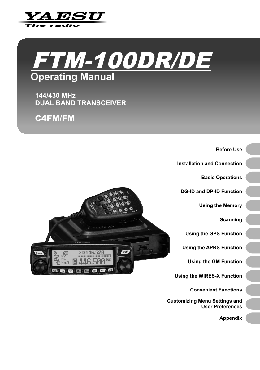
FTM-100DR/DE
Operating Manual
144/430 MHz
DUAL BAND TRANSCEIVER
C4FM/FM
Installation and Connection
Basic Operations
DG-ID and DP-ID Function
Using the Memory
Using the GPS Function
Before Use
Scanning
Using the APRS Function
Using the GM Function
Using the WIRES-X Function
Convenient Functions
Customizing Menu Settings and
User Preferences
Appendix
Page 2
Introduction
Features of this transceiver
144/430 MHz dual-band transceiver equipped with standard C4FM digital
communication modulation
Clear audio and data communication are achieved using the digital modulation
functions
With the DG-ID (Digital Group ID), the Group Monitor (GM) feature enables automati-
cally locating, and communicating with other stations that have the same DG-ID num-
ber within contact range, by utilizing a matching group ID number from 00 to 99
The Digital Personal ID (DP-ID) feature may communicate only by the transceivers
registered the individual ID information that is different for each transceiver included in
the transmission radio wave of C4FM digital communication
Wide-band receives in the 108 MHz to 999 MHz range (air band, information wireless band)
Transmit power 50 watts with cooling fan
The dot matrix LCD is mounted on the front panel
500 memory channels in the A-band and 500 channels in the B-band
Before Use
Your frequency memory channels and transceiver configuration settings can be backed
up using a micro-SD memory card. The data on the micro-SD memory card can easily
be copied to other transceivers
A choice of scanning functions (including VFO scan, memory scan)
Built-in GPS receiver unit displays your station location and movement information.
Connection to external GPS devices is enabled.
*Refer to the separate “Advance Manual”
®
Incorporated APRS
messages
*Refer to the separate “APRS Instruction Manual”
GM (Group Monitor) function in which frequently communicating members can be
registered as a group, thereby allowing location information and messages to be
exchanged
*Refer to the separate “GM Instruction Manual”
Supports Yaesu WIRES-X Internet linking, enabling communication with remote
partners via the Internet
*Refer to the separate “WIRES-X Instruction Manual”
Bluetooth adaptor unit BU-2 (sold separately) permits hands-free operation
*Refer to the separate “Advance Manual”
Voice guide unit FVS-2 (sold separately) provides voice announcements and
recording of received audio
*Refer to the separate “Advance Manual”
* The Advance Manual, WIRES-X, APRS, and GM Instruction Manuals are not
included with this product. Please download them directly from the Yaesu website.
function enables data communication of location information and
2
Page 3
Introduction
About registered trademarks and copyrights
APRS is a registered trademark of Mr. Bob Bruninga WB4APR.
SmartBeaconing is supplied by HamHUD Nichetronix.
Microsoft, Windows and Windows Vista are registered trademarks of Microsoft
Corporation in the United States and other countries.
Bluetooth
Other company and product names listed in this manual are trademarks and registered
trademarks of their respective companies.
Unauthorized reproduction or copying of a part or all of the copyrights owned by Yaesu
Musen Co., Ltd. in any form whatsoever is strictly prohibited.
®
is a registered trademark of the Bluetooth SIG.
How to read this manual
In this manual, front panel operations are described as follows.
Press
. .................................... Indicates that the key or switch is to be pressed
briefly.
Before Use
Press
The following symbols are also used in this manual:
Caution
Tip
Also note: the actual product may differ from the drawings shown in this manual.
for over one second .... Indicates that the key or switch is to be pressed for
over one second.
...Explains caution to observe during operation.
...Explains operating suggestions or useful tips.
3
Page 4
Contents
Introduction ................................................................. 2
Features of this transceiver.................................... 2
About registered trademarks and copyrights ......... 3
How to read this manual ........................................ 3
Before Use................................................................. 5
Safety Precautions (make sure to read these) ........... 5
Checking the supplied items....................................... 9
Name and function of each component .................... 10
Front panel ........................................................... 10
Front ................................................................ 10
Rear ................................................................ 12
Main body ............................................................ 12
Front ................................................................ 12
Rear ................................................................ 13
Microphone (MH-48A6JA) ................................... 14
Screen display ..................................................... 15
Input characters ................................................... 16
Switching the character type ........................... 16
Deleting the input characters .......................... 16
Moving the cursor to the left ............................ 16
Moving the cursor to the right .......................... 16
Deleting the most recently input character ...... 16
Completing input ............................................. 16
Installation and Connection .................................. 17
Before Use
Installing the transceiver ........................................... 17
Precautions on installation ................................... 17
Installation location when used in a mobile unit ... 18
About the antenna................................................ 19
Installing the antenna ...................................... 19
Installing the main body ....................................... 20
Installing the front panel ....................................... 21
Connecting the transceiver ....................................... 22
Connecting the front panel to the main body ....... 22
Connecting the microphone ................................. 22
Connecting the antenna ....................................... 22
Connecting the power supply ................................... 23
Connecting the car battery .............................. 23
Connecting the external power supply
equipment ....................................................... 23
Basic Operations .................................................... 24
Receiving .................................................................. 24
Turning the power on ........................................... 24
Switching the power off ........................................ 24
Inputting the call sign ........................................... 24
Toggling the operating band ................................ 25
Adjusting the volume level ................................... 25
Adjusting the squelch level .................................. 26
Tuning in to the frequency ................................... 27
Changing the frequency steps ............................. 27
Switching the operation mode.............................. 28
Selecting communication mode ........................... 29
Switching the modulation mode ........................... 30
Communicating......................................................... 31
Transmitting ......................................................... 31
Adjusting the transmit power ........................... 32
Communicating in FM mode ................................ 32
Communicating using the repeater ...................... 32
Tone Calling (1750 Hz) .................................... 33
Changing the 100.0 Hz CTCSS tone squelch . 33
Other settings ........................................................... 34
Locking the DIAL and keys .................................. 34
Adjusting the date and time ................................. 34
Restoring defaults (All Reset) .............................. 36
DG-ID and DP-ID Function ..................................... 37
Digital Group ID (DG-ID) function ............................. 37
Communicating only with the specific members
by setting the DG-ID number except for “00” ....... 37
Digital Personal ID (DP-ID) function ......................... 39
Registering the DP-ID to a DR-2X
digital repeater ..................................................... 39
Register the transceivers ..................................... 39
Deleting the registered DP-ID .............................. 40
Using the Memory .................................................. 41
Registering to the memory channel ..................... 41
Recalling memories ............................................. 42
Recalling the home channel................................. 43
Changing the frequency of the home channel
Clearing memories ............................................... 45
Naming a memory channel .................................. 46
Displaying the memory tag .............................. 48
Split memory ........................................................ 48
Receiving Weather Broadcast Channels
(USA version only) ............................................... 49
Assigning the “WX” function to a
programmable key on the microphone ............ 49
Recalling the weather channels ...................... 49
Listening the weather alert .............................. 50
Scanning ................................................................. 51
Searching for signals ................................................ 51
VFO scan ............................................................. 51
Selecting the receiver operation performed
after scanning stops ........................................ 52
Memory scan ....................................................... 53
Selecting the scanning method ....................... 54
Using the GPS Function ........................................ 55
Using the APRS Function ...................................... 56
What is the APRS (Automatic Packet Reporting
System) function? ..................................................... 56
Using the GM Function .......................................... 57
What is the GM (Group Monitor) Function?.............. 57
How to use the GM function ..................................... 57
Using the WIRES-X Function ................................. 59
What is the WIRES-X Function? .............................. 59
Convenient Functions ............................................ 60
Communicating with specific stations ....................... 60
Using the tone squelch function ........................... 60
Using the digital code squelch function ............... 60
Using the new pager function .............................. 60
Notification of incoming calls from
partner stations using the bell function ................ 60
Exchanging messages or images............................. 60
Setup menu basic operations ................................... 61
Setup-menu listing .................................................... 62
Appendix ................................................................. 68
Optional components................................................ 68
Specifications ........................................................... 69
... 44
4
Page 5

Before Use
Safety Precautions (make sure to read these)
Make sure to read this manual in order to use this radio safely and correctly.
Before using this product, note that the company shall not be liable for any damages
suffered by the customer or third parties, or for any failures and faults that occur during
the use or misuse of this product, unless otherwise provided for under the law.
Type and meaning of the marks
This symbol indicates the possibility of death or serious
DANGER
WARNING
CAUTION
injury being inflicted on the user and the surrounding
people when these instructions are ignored and the product
is mishandled.
This symbol indicates the possibility of death or serious
injury being inflicted on the user and the surrounding
people when these instructions are ignored and the product
is mishandled.
This symbol indicates the possibility of physical
impediments occurring or impediments being inflicted
on the user and the surrounding people when these
instructions are ignored and the product is mishandled.
Before Use
Type and meaning of symbols
Prohibited actions that must not be attempted, in order to use this radio
safely.
For example,
Precautions that must be adhered to in order to use this radio safely. For
example,
Do not use the device in “regions or
aircrafts and vehicles where its use
is prohibited” such as in hospitals
and airplanes.
This may exert an impact on electronic
and medical devices.
Do not use this product while driving
or riding a motorbike. This may
result in accidents.
Make sure to stop the car in a safe
location first before use if the device is
going to be used by the driver.
signifies that disassembly is prohibited.
signifies that the power supply is to be disconnected.
DANGER
Never touch the antenna during
transmission.
This may result in injury, electric shock
and equipment failure.
When an alarm goes off with the
external antenna connected, cut
off the power supply to this radio
immediately and disconnect the
external antenna from this radio.
If not, this may result in fire, electric
shock and equipment failure.
5
Page 6
Safety Precautions (make sure to read these)
Before Use
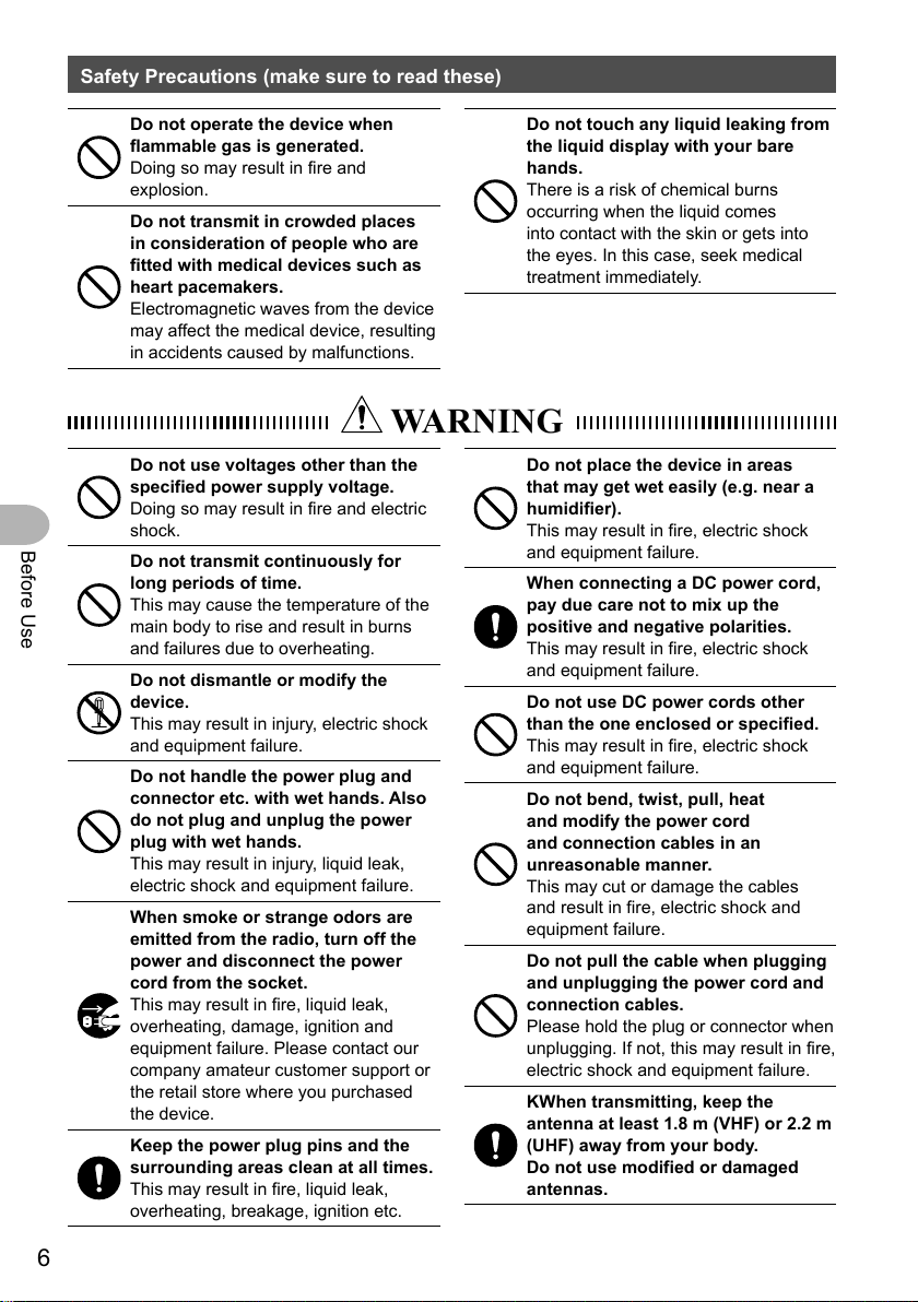
Do not operate the device when
flammable gas is generated.
Doing so may result in fire and
explosion.
Do not transmit in crowded places
in consideration of people who are
fitted with medical devices such as
heart pacemakers.
Electromagnetic waves from the device
may affect the medical device, resulting
in accidents caused by malfunctions.
WARNING
Do not use voltages other than the
specified power supply voltage.
Doing so may result in fire and electric
shock.
Do not transmit continuously for
long periods of time.
This may cause the temperature of the
main body to rise and result in burns
and failures due to overheating.
Do not dismantle or modify the
device.
This may result in injury, electric shock
and equipment failure.
Do not handle the power plug and
connector etc. with wet hands. Also
do not plug and unplug the power
plug with wet hands.
This may result in injury, liquid leak,
electric shock and equipment failure.
When smoke or strange odors are
emitted from the radio, turn off the
power and disconnect the power
cord from the socket.
This may result in fire, liquid leak,
overheating, damage, ignition and
equipment failure. Please contact our
company amateur customer support or
the retail store where you purchased
the device.
Keep the power plug pins and the
surrounding areas clean at all times.
This may result in fire, liquid leak,
overheating, breakage, ignition etc.
Do not touch any liquid leaking from
the liquid display with your bare
hands.
There is a risk of chemical burns
occurring when the liquid comes
into contact with the skin or gets into
the eyes. In this case, seek medical
treatment immediately.
Do not place the device in areas
that may get wet easily (e.g. near a
humidifier).
This may result in fire, electric shock
and equipment failure.
When connecting a DC power cord,
pay due care not to mix up the
positive and negative polarities.
This may result in fire, electric shock
and equipment failure.
Do not use DC power cords other
than the one enclosed or specified.
This may result in fire, electric shock
and equipment failure.
Do not bend, twist, pull, heat
and modify the power cord
and connection cables in an
unreasonable manner.
This may cut or damage the cables
and result in fire, electric shock and
equipment failure.
Do not pull the cable when plugging
and unplugging the power cord and
connection cables.
Please hold the plug or connector when
unplugging. If not, this may result in fire,
electric shock and equipment failure.
KWhen transmitting, keep the
antenna at least 1.8 m (VHF) or 2.2 m
(UHF) away from your body.
Do not use modified or damaged
antennas.
6
Page 7

Safety Precautions (make sure to read these)
Do not use the device when the
power cord and connection cables
are damaged, and when the DC
power connector cannot be plugged
in tightly.
Please contact our company amateur
customer support or the retail store
where you purchased the device as this
may result in fire, electric shock and
equipment failure.
Never cut off the fuse holder of the
DC power cord.
This may cause short-circuiting and
result in ignition and fire.
Do not use fuses other than those
specified.
Doing so may result in fire and
equipment failure.
Do not allow metallic objects such
as wires and water to get inside the
product.
This may result in fire, electric shock
and equipment failure.
CAUTION
Refrain from using headphones and
earphones at a loud volume.
Continuous exposure to loud volumes
may result in hearing impairment.
Disconnect the power cord
and connection cables before
incorporating items sold separately
and replacing the fuse.
This may result in fire, electric shock
and equipment failure.
Follow the instructions given when
installing items sold separately and
replacing the fuse.
This may result in fire, electric shock
and equipment failure.
Do not use the device when the
alarm goes off.
For safety reasons, please pull the
power plug of the DC power equipment
connected to the product out of the AC
socket.
Never touch the antenna as well. This
may result in fire, electric shock and
equipment failure due to thunder.
Before Use
Do not place this device near a
heating instrument or in a location
exposed to direct sunlight.
This may result in deformation and
discoloration.
Do not place this device in a location
where there is a lot of dust and
humidity.
Doing so may result in fire and
equipment failure.
Stay as far away from the antenna as
possible during transmission.
Long-term exposure to electromagnetic
radiation may have a negative effect on
the human body.
Do not wipe the case using thinner
and benzene etc.
Please use a soft and dry piece of cloth
to wipe away the stains on the case.
For safety reasons, switch off the
power and pull out the DC power
cord connected to the DC power
connector when the device is not
going to be used for a long period
of time.
If not, this may result in fire and
overheating.
Do not throw or subject the device to
strong impact forces.
This may result in equipment failure.
Do not the put this device near
magnetic cards and video tapes.
The data in the cash card and video
tape etc. may be erased.
Do not turn on the volume too
high when using a headphone or
earphone.
This may result in hearing impairment.
7
Page 8
Safety Precautions (make sure to read these)
Before Use
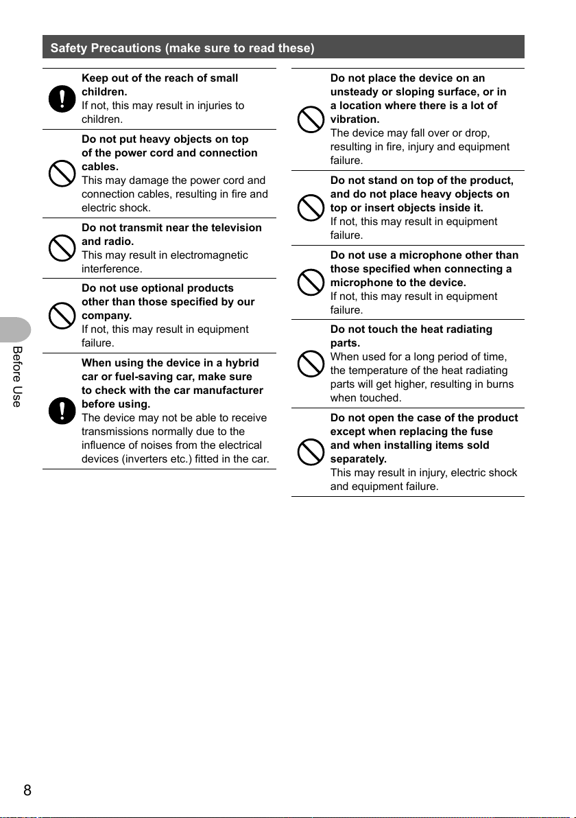
Keep out of the reach of small
children.
If not, this may result in injuries to
children.
Do not put heavy objects on top
of the power cord and connection
cables.
This may damage the power cord and
connection cables, resulting in fire and
electric shock.
Do not transmit near the television
and radio.
This may result in electromagnetic
interference.
Do not use optional products
other than those specified by our
company.
If not, this may result in equipment
failure.
When using the device in a hybrid
car or fuel-saving car, make sure
to check with the car manufacturer
before using.
The device may not be able to receive
transmissions normally due to the
influence of noises from the electrical
devices (inverters etc.) fitted in the car.
Do not place the device on an
unsteady or sloping surface, or in
a location where there is a lot of
vibration.
The device may fall over or drop,
resulting in fire, injury and equipment
failure.
Do not stand on top of the product,
and do not place heavy objects on
top or insert objects inside it.
If not, this may result in equipment
failure.
Do not use a microphone other than
those specified when connecting a
microphone to the device.
If not, this may result in equipment
failure.
Do not touch the heat radiating
parts.
When used for a long period of time,
the temperature of the heat radiating
parts will get higher, resulting in burns
when touched.
Do not open the case of the product
except when replacing the fuse
and when installing items sold
separately.
This may result in injury, electric shock
and equipment failure.
8
Page 9
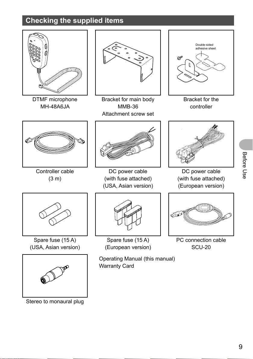
Checking the supplied items
Double-sided
adhesive sheet
DTMF microphone
MH-48A6JA
Controller cable
(3 m)
Spare fuse (15 A)
(USA, Asian version)
Bracket for main body
MMB-36
Attachment screw set
DC power cable
(with fuse attached)
(USA, Asian version)
Spare fuse (15 A)
(European version)
Operating Manual (this manual)
Warranty Card
Bracket for the
controller
Before Use
DC power cable
(with fuse attached)
(European version)
PC connection cable
SCU-20
Stereo to monaural plug
9
Page 10
Name and function of each component
Front panel
Front
①
②
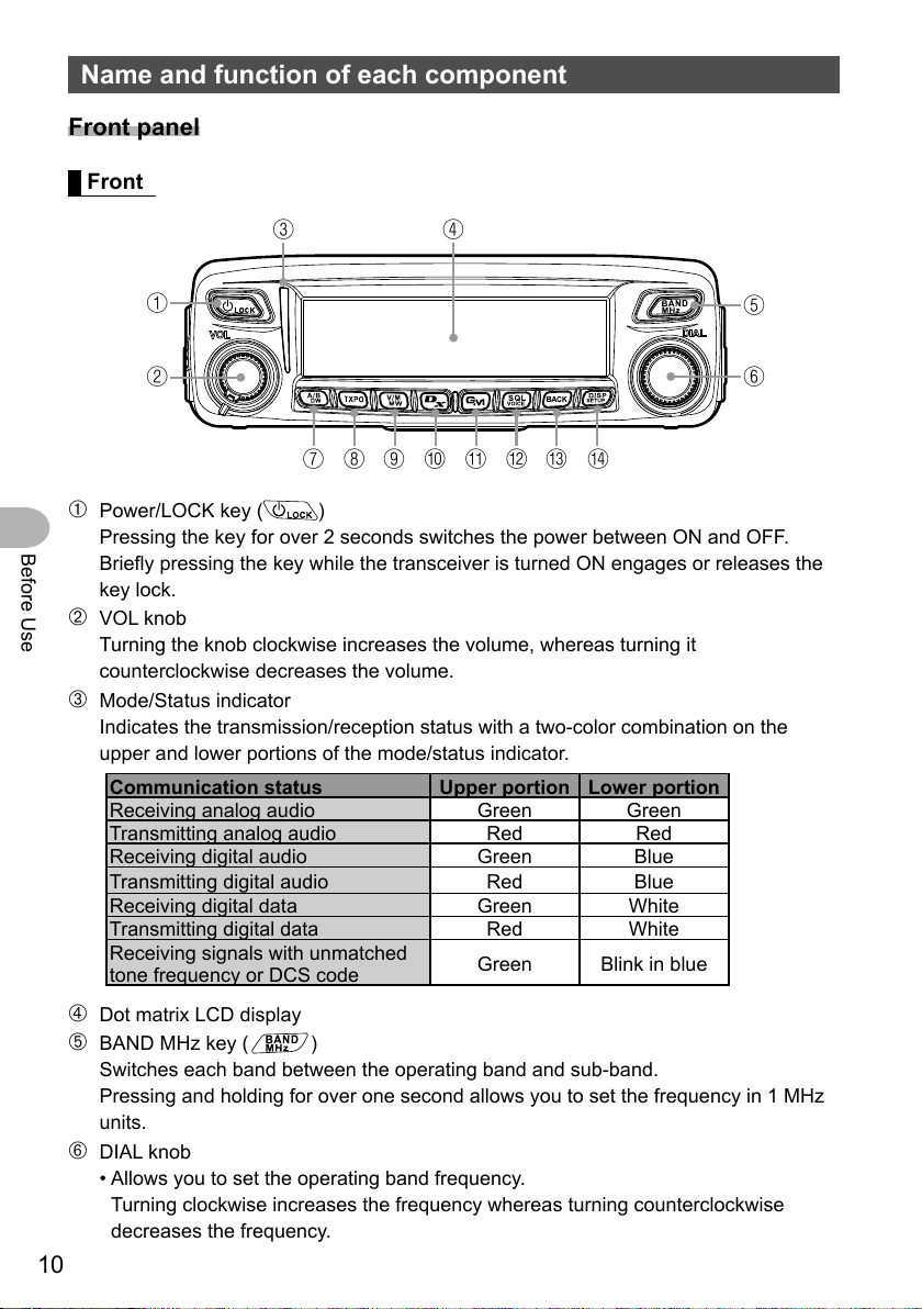
➀ Power/LOCK key ( )
Before Use
Pressing the key for over 2 seconds switches the power between ON and OFF.
Briefly pressing the key while the transceiver is turned ON engages or releases the
key lock.
➁ VOL knob
Turning the knob clockwise increases the volume, whereas turning it
counterclockwise decreases the volume.
➂ Mode/Status indicator
Indicates the transmission/reception status with a two-color combination on the
upper and lower portions of the mode/status indicator.
Communication status Upper portion Lower portion
Receiving analog audio Green Green
Transmitting analog audio Red Red
Receiving digital audio Green Blue
Transmitting digital audio Red Blue
Receiving digital data Green White
Transmitting digital data Red White
Receiving signals with unmatched
tone frequency or DCS code
③
⑦⑧⑨⑩
④
⑤
⑥
⑬ ⑭⑪⑫
Green Blink in blue
➃ Dot matrix LCD display
➄ BAND MHz key (
Switches each band between the operating band and sub-band.
Pressing and holding for over one second allows you to set the frequency in 1 MHz
units.
)
➅ DIAL knob
• Allows you to set the operating band frequency.
Turning clockwise increases the frequency whereas turning counterclockwise
decreases the frequency.
10
Page 11
Name and function of each component
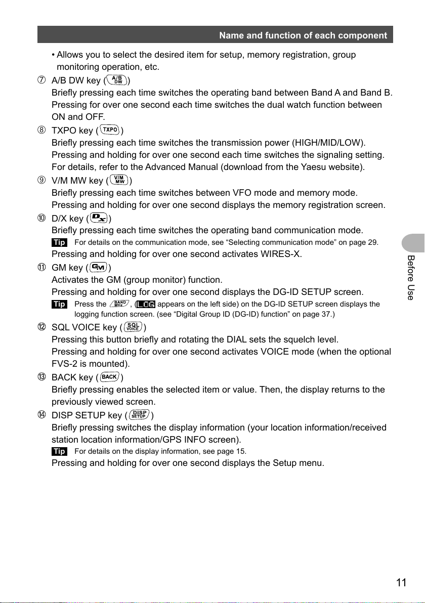
• Allows you to select the desired item for setup, memory registration, group
monitoring operation, etc.
➆ A/B DW key (
Briefly pressing each time switches the operating band between Band A and Band B.
Pressing for over one second each time switches the dual watch function between
ON and OFF.
➇ TXPO key (
Briefly pressing each time switches the transmission power (HIGH/MID/LOW).
Pressing and holding for over one second each time switches the signaling setting.
For details, refer to the Advanced Manual (download from the Yaesu website).
➈ V/M MW key (
Briefly pressing each time switches between VFO mode and memory mode.
Pressing and holding for over one second displays the memory registration screen.
➉ D/X key (
Briefly pressing each time switches the operating band communication mode.
Tip For details on the communication mode, see “Selecting communication mode” on page 29.
Pressing and holding for over one second activates WIRES-X.
GM key ( )
Activates the GM (group monitor) function.
Pressing and holding for over one second displays the DG-ID SETUP screen.
Tip Press the , (
logging function screen. (see “Digital Group ID (DG-ID) function” on page 37.)
SQL VOICE key ( )
Pressing this button briefly and rotating the DIAL sets the squelch level.
Pressing and holding for over one second activates VOICE mode (when the optional
FVS-2 is mounted).
BACK key ( )
Briefly pressing enables the selected item or value. Then, the display returns to the
previously viewed screen.
DISP SETUP key ( )
Briefly pressing switches the display information (your location information/received
station location information/GPS INFO screen).
Tip For details on the display information, see page 15.
Pressing and holding for over one second displays the Setup menu.
)
)
)
)
appears on the left side) on the DG-ID SETUP screen displays the
Before Use
11
Page 12
Name and function of each component
②
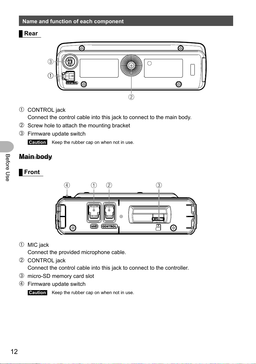
Rear
③
①①
➀ CONTROL jack
Connect the control cable into this jack to connect to the main body.
➁ Screw hole to attach the mounting bracket
➂ Firmware update switch
Caution Keep the rubber cap on when not in use.
Before Use
Main body
Front
①②③④
➀ MIC jack
Connect the provided microphone cable.
➁ CONTROL jack
Connect the control cable into this jack to connect to the controller.
➂ micro-SD memory card slot
➃ Firmware update switch
Caution Keep the rubber cap on when not in use.
12
Page 13
Name and function of each component
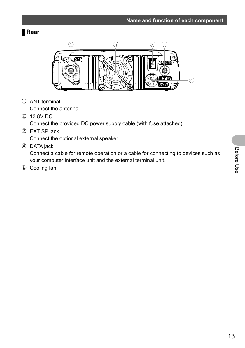
Rear
①⑤②④③
➀ ANT terminal
Connect the antenna.
➁ 13.8V DC
Connect the provided DC power supply cable (with fuse attached).
➂ EXT SP jack
Connect the optional external speaker.
➃ DATA jack
Connect a cable for remote operation or a cable for connecting to devices such as
your computer interface unit and the external terminal unit.
➄ Cooling fan
Before Use
13
Page 14
Name and function of each component
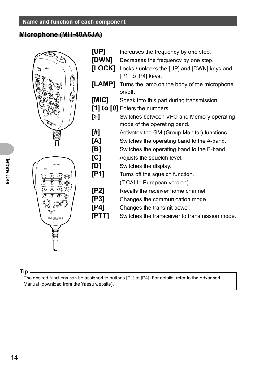
Microphone (MH-48A6JA)
Before Use
MIC
ABC
DEF
LOCK
A
3
1
2
JKL
GHI
MNO
4
5
6
B
TUV
PQRS
WXYZ
7
P1
DTMF MICROPHONE
8
0
P2
MH-48
LAMP
9
C
D
P4
P3
[UP] Increases the frequency by one step.
[DWN] Decreases the frequency by one step.
[LOCK] Locks / unlocks the [UP] and [DWN] keys and
[P1] to [P4] keys.
[LAMP] Turns the lamp on the body of the microphone
on/off.
[MIC] Speak into this part during transmission.
[1] to [0] Enters the numbers.
[✽] Switches between VFO and Memory operating
mode of the operating band.
[#] Activates the GM (Group Monitor) functions.
[A] Switches the operating band to the A-band.
[B] Switches the operating band to the B-band.
[C] Adjusts the squelch level.
[D] Switches the display.
[P1] Turns off the squelch function.
(T.CALL: European version)
[P2] Recalls the receiver home channel.
[P3] Changes the communication mode.
[P4] Changes the transmit power.
[PTT] Switches the transceiver to transmission mode.
Tip
The desired functions can be assigned to buttons [P1] to [P4]. For details, refer to the Advanced
Manual (download from the Yaesu website).
14
Page 15
Name and function of each component
③
Screen display
①
④
②
⑤
⑦⑥
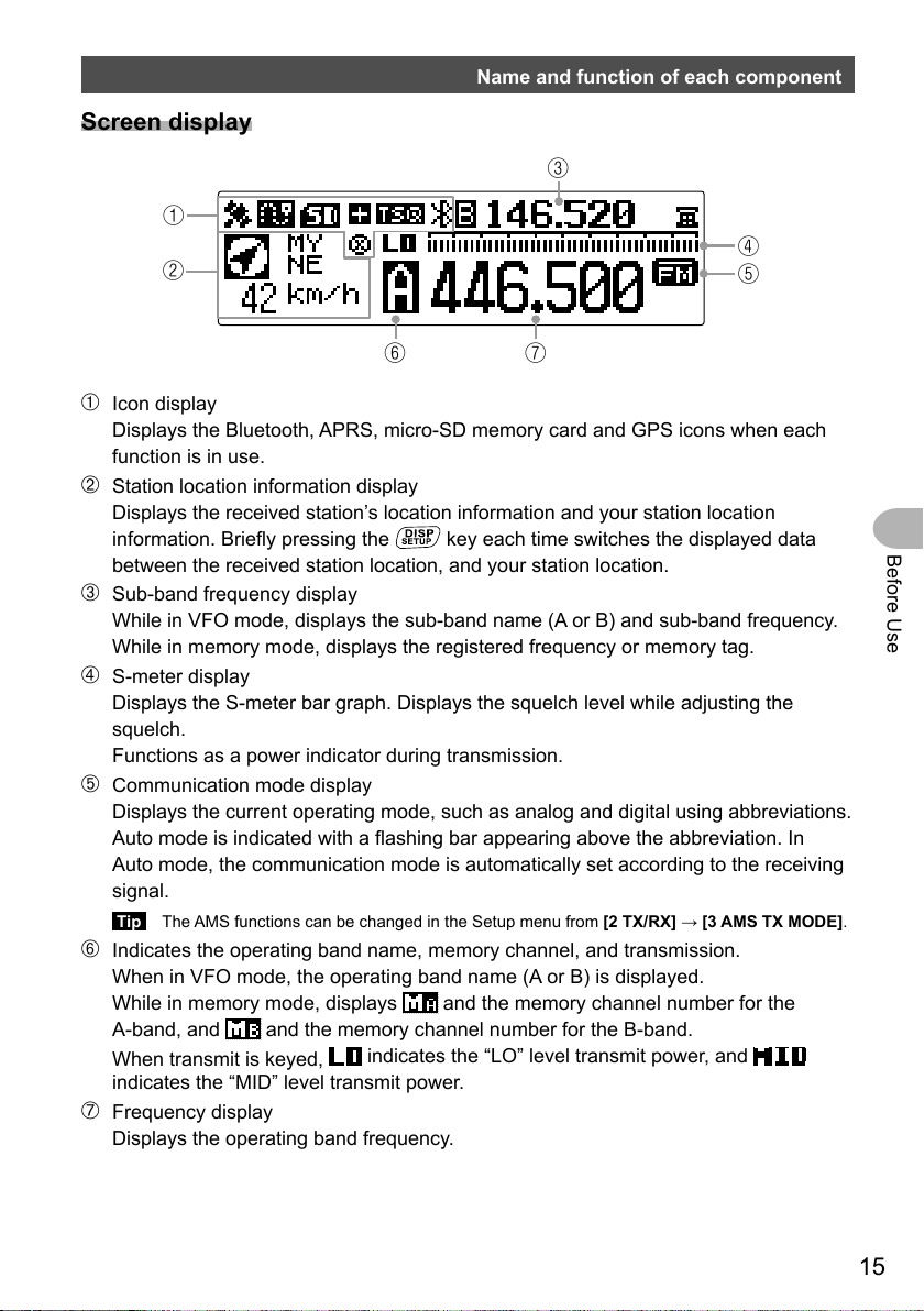
➀ Icon display
Displays the Bluetooth, APRS, micro-SD memory card and GPS icons when each
function is in use.
➁ Station location information display
Displays the received station’s location information and your station location
information. Briefly pressing the
between the received station location, and your station location.
key each time switches the displayed data
➂ Sub-band frequency display
While in VFO mode, displays the sub-band name (A or B) and sub-band frequency.
While in memory mode, displays the registered frequency or memory tag.
➃ S-meter display
Displays the S-meter bar graph. Displays the squelch level while adjusting the
squelch.
Functions as a power indicator during transmission.
➄ Communication mode display
Displays the current operating mode, such as analog and digital using abbreviations.
Auto mode is indicated with a flashing bar appearing above the abbreviation. In
Auto mode, the communication mode is automatically set according to the receiving
signal.
Tip The AMS functions can be changed in the Setup menu from [2 TX/RX] → [3 AMS TX MODE].
➅ Indicates the operating band name, memory channel, and transmission.
When in VFO mode, the operating band name (A or B) is displayed.
While in memory mode, displays
A-band, and
When transmit is keyed,
indicates the “MID” level transmit power.
and the memory channel number for the B-band.
indicates the “LO” level transmit power, and
➆ Frequency display
Displays the operating band frequency.
and the memory channel number for the
Before Use
15
Page 16
Name and function of each component
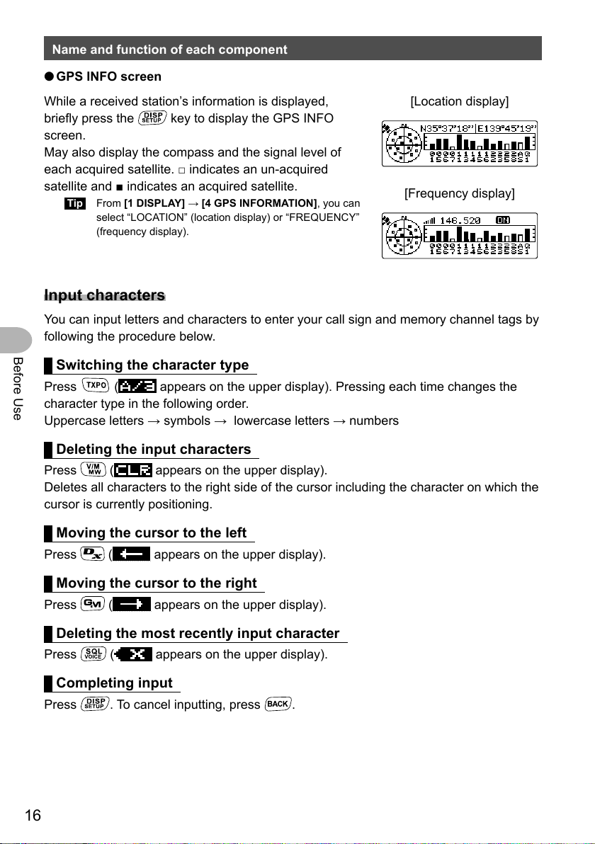
● GPS INFO screen
While a received station’s information is displayed,
briefly press the
screen.
May also display the compass and the signal level of
each acquired satellite. □ indicates an un-acquired
satellite and ■ indicates an acquired satellite.
Tip From [1 DISPLAY] → [4 GPS INFORMATION], you can
select “LOCATION” (location display) or “FREQUENCY”
(frequency display).
key to display the GPS INFO
[Location display]
[Frequency display]
Input characters
You can input letters and characters to enter your call sign and memory channel tags by
following the procedure below.
Before Use
Switching the character type
Press ( appears on the upper display). Pressing each time changes the
character type in the following order.
Uppercase letters → symbols → lowercase letters → numbers
Deleting the input characters
Press ( appears on the upper display).
Deletes all characters to the right side of the cursor including the character on which the
cursor is currently positioning.
Moving the cursor to the left
Press ( appears on the upper display).
Moving the cursor to the right
Press ( appears on the upper display).
Deleting the most recently input character
Press ( appears on the upper display).
Completing input
Press . To cancel inputting, press .
16
Page 17
Installation and Connection
Installing the transceiver
Precautions on installation
Note the following when installing the transceiver.
Do not install the transceiver in a place where it would be exposed to direct sunlight,
high temperatures, excessive humidity, dusty conditions, or extreme vibrations.
Install the transceiver in a well-ventilated position, so that heat dissipation is not
hindered, because the heat sinks will become hot when the transceiver is run for an
extended period of time.
Do not place any objects on the transceiver.
Do not attempt to lift the front panel by holding onto just the knob or control cable.
This transceiver requires a 13.8 V DC power supply.
When using this transceiver in a mobile unit, ensure that the car battery is a 12 V
type. Never connect this transceiver to a 24 V battery of a large vehicle.
Never connect the transceiver to a 100 V AC power source.
Heed caution as hum and noise may be introduced, depending on the installation
conditions of the external power source.
Install the transceiver as far away as possible from TVs and radios. Failing to do so
may result in noise interference such as broadcast interference (BCI) or television
interference (TVI) from radios and TVs respectively.
Never attempt to install this transceiver near indoor antenna elements.
Installation and Connection
17
Page 18
Installing the transceiver
Installation location when used in a mobile unit
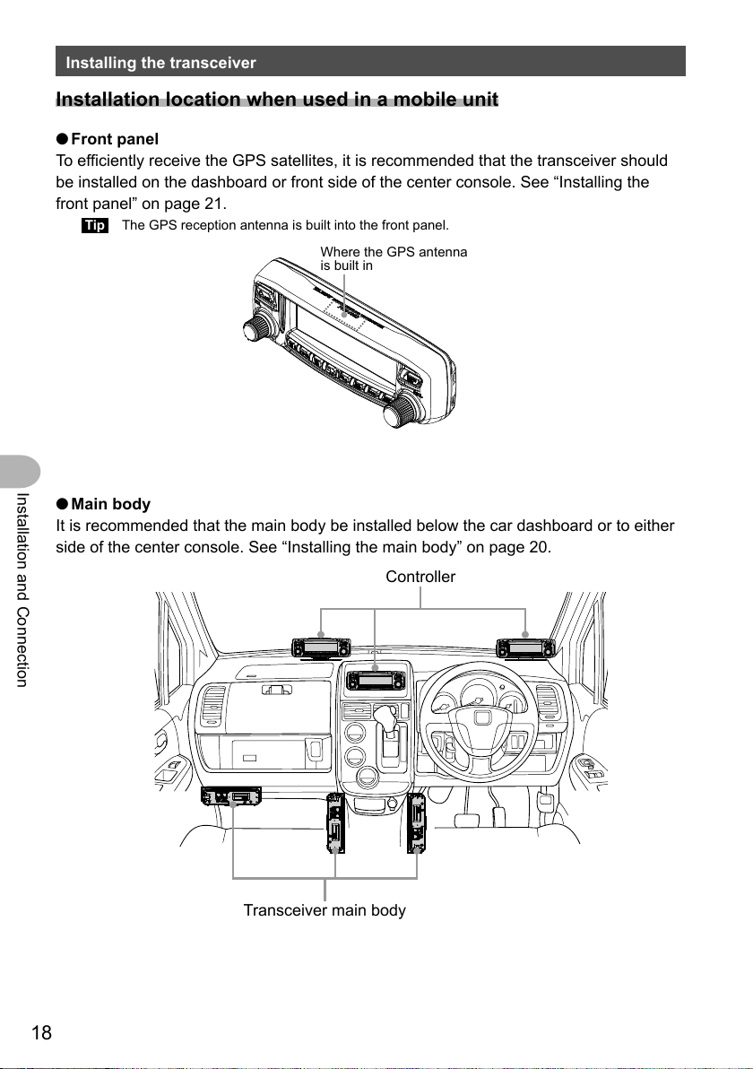
● Front panel
To efficiently receive the GPS satellites, it is recommended that the transceiver should
be installed on the dashboard or front side of the center console. See “Installing the
front panel” on page 21.
Tip The GPS reception antenna is built into the front panel.
Where the GPS antenna
is built in
Installation and Connection
● Main body
It is recommended that the main body be installed below the car dashboard or to either
side of the center console. See “Installing the main body” on page 20.
Controller
18
Transceiver main body
Page 19
Installing the transceiver
About the antenna
The antenna is an extremely important part for both transmitting and receiving. The
antenna type and its inherent characteristics determine whether the performance of the
transceiver can be fully realized. As such, please note the following:
Use an antenna that is suitable for the installation conditions and application
objective.
Use an antenna that is suitable for the operating frequency band.
Use an antenna and a coaxial cable with a characteristic feed point impedance of
50Ω.
Adjust the VSWR (Voltage Standing Wave Ratio) until it is 1.5 or less for an antenna
with an adjusted impedance of 50Ω.
Keep the coaxial cable routing length as short as possible.
Installing the antenna
● Antenna installation in a mobile unit
Install the antenna base to the rear of the car (rear bumper, trunk, rear gate, etc.) and
then attach the antenna to the base.
Cautions
z Verify that the antenna base is securely grounded to the car body.
z When using a coaxial cable included with a commercially-available on-vehicle antenna, lay the
cable in a way to keep it as short as possible.
z Do not allow rain water or moisture to penetrate the entrance of the cable or connectors when
routing the coaxial cable inside the vehicle.
Installation and Connection
● Antenna installation when using a fixed station
For use in an outdoor setting, there are omni-directional antennas and a variety of
directional antennas.
• Omni-directional antennas such as the GP (Ground Plane) antenna are suitable for
communications with a local station or mobile stations in all directions.
• Directional antennas such as the Yagi antenna are suitable for communications with a
specific station or a remote station in a specific direction.
Cautions
z Create a loop (slack) in the coaxial cable directly underneath the antenna and fasten the coaxial
cable so that the weight of the cable does not pull on the antenna.
z When installing the antenna, take into consideration the securing supports and how the guy wires
are positioned, so that the antenna does not fall over or get blown away by strong wind gusts.
19
Page 20
Installing the transceiver
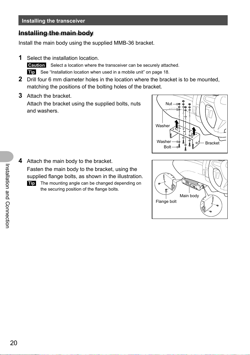
Installing the main body
Install the main body using the supplied MMB-36 bracket.
1 Select the installation location.
Caution Select a location where the transceiver can be securely attached.
Tip See “Installation location when used in a mobile unit” on page 18.
2 Drill four 6 mm diameter holes in the location where the bracket is to be mounted,
matching the positions of the bolting holes of the bracket.
3 Attach the bracket.
Attach the bracket using the supplied bolts, nuts
and washers.
Nut
Washer
4 Attach the main body to the bracket.
Installation and Connection
Fasten the main body to the bracket, using the
supplied flange bolts, as shown in the illustration.
Tip The mounting angle can be changed depending on
the securing position of the flange bolts.
Washer
Bolt
Flange bolt
Bracket
Main body
20
Page 21
Installing the transceiver
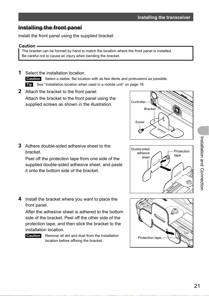
Installing the front panel
Install the front panel using the supplied bracket.
Caution
The bracket can be formed by hand to match the location where the front panel is installed.
Be careful not to cause an injury when bending the bracket.
1 Select the installation location.
Caution Select a stable, flat location with as few dents and protrusions as possible.
Tip See “Installation location when used in a mobile unit” on page 18.
2 Attach the bracket to the front panel.
Attach the bracket to the front panel using the
supplied screws as shown in the illustration.
Controller
Bracket
Screw
Installation and Connection
3 Adhere double-sided adhesive sheet to the
bracket.
Peel off the protection tape from one side of the
supplied double-sided adhesive sheet, and paste
it onto the bottom side of the bracket.
4 Install the bracket where you want to place the
front panel.
After the adhesive sheet is adhered to the bottom
side of the bracket, Peel off the other side of the
protection tape, and then stick the bracket to the
installation location.
Caution Remove all dirt and dust from the installation
location before affixing the bracket.
Double-sided
adhesive
sheet
Protection tape
Protection
tape
21
Page 22
Connecting the transceiver
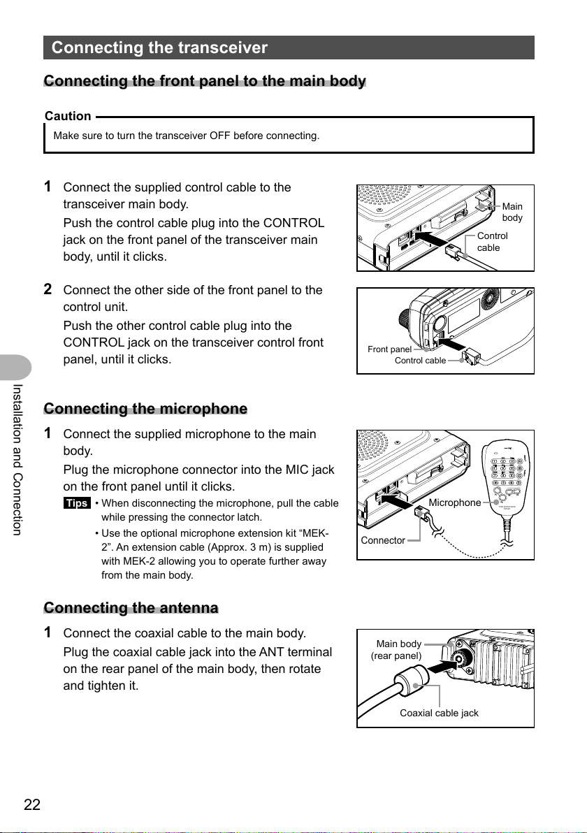
Connecting the front panel to the main body
Caution
Make sure to turn the transceiver OFF before connecting.
1 Connect the supplied control cable to the
transceiver main body.
Push the control cable plug into the CONTROL
jack on the front panel of the transceiver main
body, until it clicks.
2 Connect the other side of the front panel to the
control unit.
Push the other control cable plug into the
CONTROL jack on the transceiver control front
panel, until it clicks.
Installation and Connection
Connecting the microphone
1
Connect the supplied microphone to the main
body.
Plug the microphone connector into the MIC jack
on the front panel until it clicks.
Tips • When disconnecting the microphone, pull the cable
while pressing the connector latch.
• Use the optional microphone extension kit “MEK-
2”. An extension cable (Approx. 3 m) is supplied
with MEK-2 allowing you to operate further away
from the main body.
Front panel
Control cable
Connector
Microphone
Control
cable
1
GHI
4
PQRS
7
P
1
DTMF MICROPHONE
Main
body
MIC
ABC
2
JKL
MNO
5
TUV
WXYZ
8
0
P3
P2
MH-48
DEF
LOCK
A
3
6
B
LAMP
9
C
D
P4
Connecting the antenna
1
Connect the coaxial cable to the main body.
Plug the coaxial cable jack into the ANT terminal
on the rear panel of the main body, then rotate
and tighten it.
22
Main body
(rear panel)
Coaxial cable jack
Page 23

Connecting the power supply
DC power supply
Fuse holder
outlet
Fuse holder
Connecting the car battery
When using the transceiver as a mobile unit, connect the DC power supply cable to the
car battery.
Cautions
z Use the transceiver in a car with a negative ground system where the minus (−) pole of the battery
is connected to the car body.
z Check the car battery specification is 12 V. Do not connect the transceiver to the 24 V battery of a
large vehicle.
z Do not use the cigarette lighter socket inside the car as a power source.
Plug into the connector of the main body power cable until it clicks.
cable (supplied)
Power cable
(DC 13.8 V)
Main body rear panel
Red
Black
DC 12 V battery
Connecting the external power supply equipment
When using the transceiver as a fixed station, use an external power source.
Cautions
z Use an external power source capable of supplying DC 13.8 V, a current capacity of 20 A or more.
z Make sure to switch OFF the power of the external power source before connecting.
Direct current
Black
Power cable
Main body rear panel
(DC 13.8 V)
DC power supply
cable (supplied)
Red
AC power
power supply
Installation and Connection
23
Page 24

Receiving
Turning the power on
Basic Operations
1 Press and hold
The power switches on, and the display appears on
the screen.
<When using the same call sign for digital and APRS>
<When using separate call signs for digital and APRS>
The call sign for digital appears on the left and the
call sign for APRS appears on the right.
Tips • When turning the transceiver on for the first time, or after resetting the transceiver, a screen
requesting input of a call sign appears.
Basic Operations
• When turning the transceiver on thereafter, the previously registered call sign will be
displayed.
for over 2 seconds.
Switching the power off
1
Press and hold
The screen display disappears, and the power switches off.
for over 2 seconds.
Inputting the call sign
A screen requesting input of a call sign appears when
turning the transceiver on for the first time, or after
resetting the transceiver.
The call sign is used to identify the transmitting station
when communicating in digital mode.
1 Rotate the DIAL to select characters, then press
.
Tips • Up to 10 characters (alphanumeric characters including
hyphen) can be entered.
• See “Input characters” on page 16 on how to operate
the character input screen.
24
Page 25

Receiving
2 Press
The display changes.
The entered call sign appears at the bottom of the
screen, and the screen switches to the frequency
display screen.
.
Toggling the operating band
Normally, 2 operating bands appear on the top half and bottom half of the screen. The
frequency and modulation mode may be changed only for the band on the top half of
the screen, which is called “operating band”. The other band, displayed on the bottom
half of the screen, is not in operation, and is called the “sub-band”.
1 Press
Each press toggles the operating band between
A-band and B-band.
Caution The operating band signals and sub-band signals
.
cannot be received simultaneously.
Basic Operations
Adjusting the volume level
1
Rotate VOL.
Clockwise rotation increases the volume, whereas
counterclockwise rotation decreases the volume.
25
Page 26

Receiving
Adjusting the squelch level
Annoying noises can be eliminated when there is no signal present. The A-band and
B-band squelch levels can be individually adjusted. Increasing the squelch level will be
more effective in reducing noise; however setting the squelch level too high may block
weak signals. Adjust the squelch level as required.
1 Press .
The current squelch level is shown on the sub-band
display and on the SQL meter.
Tip In digital mode, noise does not occur even if the squelch
level is set to 0.
2 Rotate the DIAL to adjust the squelch level.
Basic Operations
The squelch level value is shown on the sub-band
display, and the level is displayed on the SQL meter.
Tip The display returns to the normal operating screen three
seconds after the squelch is adjusted, or if no adjustment
is made.
26
Page 27

Tuning in to the frequency
0
● Using the DIAL
1 Rotate the DIAL.
Clockwise rotation tunes the frequency upwards,
whereas counterclockwise rotation tunes the
frequency downwards.
● Using the microphone
Receiving
Press [UP] and [DWN] briefly
Pressing [UP] briefly, tunes the frequency upwards.
Whereas pressing [DWN] briefly tunes the frequency in
the downward direction.
Number
keys
Using the number keys
Use the
to 9 number keys to directly input the
frequency.
Changing the frequency steps
The DIAL and microphone [UP]/[DWN] keys frequency tuning step can be changed.
1 Press
The Setup menu appears.
for over one second.
DWN
UP
Basic Operations
27
Page 28

Receiving
2 Rotate the DIAL to select [8 CONFIG], then press
.
The menu list appears.
3 Rotate the DIAL to select [7 FM AM STEP], then
press
.
4 Rotate the DIAL to select the desired frequency step.
The frequency steps change in the following order:
“AUTO” → “5.00 KHz” → “6.25 KHz” → “8.33 KHz”
→ “10.00 KHz” → “12.50 KHz” → “15.00 KHz” →
“20.00 KHz” → “25.00 KHz” → “50.00 KHz” →
“100.00 KHz”
Tips • The default setting: AUTO
• The 8.33 kHz frequency step can be selected only on
the Air band.
• The 5 kHz, 6.25 kHz or 15 kHz frequency step cannot
be selected on 480 MHz or higher frequency.
5 Press and hold for over one second.
The selected frequency step is set, and the display returns to the previous operating
Basic Operations
display.
Tip To return to the previous operating display press 3 times.
Switching the operation mode
The operating mode can be switched between VFO mode and MEMORY mode. In VFO
mode, the operating frequency may be freely adjusted; in MEMORY mode, the memory
channels are recalled and displayed on the screen for operation.
1 Select the desired operating band.
2 Press .
The display switches to MEMORY mode.
When a name (tag) has been assigned to the
or and the memory channel number appear
on the operating band name display.
Tips • appears on the A-band.
•
memory channel, the tag appears on the frequency
display or the sub-band display.
appears on the B-band.
28
Page 29

Receiving
3 Press .
The display switches to VFO mode and returns to the previous receive frequency.
Selecting communication mode
The FTM-100DR/DE transceiver is equipped with the AMS (Automatic Mode Select)
function which automatically selects from 4 modes of transmission corresponding to the
signal being received.
The transmit mode is selected according to the received signal so that C4FM digital
signals, and analog signals are received and transmitted automatically.
Press
to display “
To operate in fixed communication mode, press to switch the communication mode.
Each time
“
(AMS)”→“DN (V/D mode)”→“VW/DW (FR mode)”→“FM (analog)”
Operation mode Icon Description of modes
AMS
(Automatic Mode Select)
V/D Mode
(Voice/Data simultaneous
transmission mode)
Voice FR Mode
(Voice Full Rate Mode)
Data FR Mode
(High Speed Data
Communication Mode)
Analog FM Mode FM Analog communication using FM mode.
▀
*” on the screen.
○○
*The display differs depending on the received signal.
Display example when in AMS mode
is pressed, the communication mode changes in the following order:
▀
Transmission mode is automatically selected from 4 types
○○
according to the signal received.
” icon differs depending on the received signal.)
(“
○○
The AMS function operation can be changed from the Setup menu
setting. See page 62.
DN Calls are less prone to interruptions due to detection and
correction of voice signals during digital voice signal transmission.
This is the standard mode for C4FM Digital.
VW Digital voice data transmission using the entire 12.5 kHz band.
Enables high-quality voice communication.
DW High speed data communication using the entire 12.5 kHz band.
The transceiver automatically switches to this mode during image
transmission.
Effective when the signal is weak and audio is susceptible to
interruption in digital mode.
Basic Operations
Cautions
z In V/D mode (“DN” on the screen), location information is included in the transmitted signal during
voice communication, however, location information is not included with the Voice in the FR mode
(“VW” on the LCD).
29
Page 30

Receiving
Switching the modulation mode
In analog mode, the modulation mode can be selected from “AUTO”, “MANUAL (FM)”
and “MANUAL (AM)”.
When shipped from the factory, the mode is set to “AUTO” where the most optimal
modulation mode is automatically selected according to the frequency.
1 Select the desired operating band.
2 Press and hold
The Setup menu appears.
for over one second.
3 Rotate the DIAL to select [2 TX/RX], then press
.
The menu list appears.
4 Rotate the DIAL to select [1 ANALOG MODE
Basic Operations
SELECT], then press
The modulation mode setting value appears.
.
5 Rotate the DIAL to select the desired modulation
mode.
“1 AUTO”: Automatically switches the modulation
mode to match the frequency band.
“2 MANUAL(FM)”: Switches to FM mode.
“3 MANUAL(AM)”: Switches to AM mode.
Tip The default setting: AUTO
6 Press and hold for over one second.
Sets the selected modulation mode and returns the display to the previously viewed
screen.
Tip You can also return to the previous screen by pressing 3 times.
30
Page 31

Communicating
Transmitting
1 Press and hold [PTT] on the microphone.
MIC
In analog mode, both the upper and lower portions of
the mode/status indicator light red.
In digital mode, the upper portion of the mode/status
indicator lights red and the lower portion of the mode/
status indicator lights blue.
Analog mode: both the upper and lower portions
light red
PTT
1
GHI
4
PQRS
7
P1
ABC
2
JKL
5
TUV
8
0
P2
DTMF MICROPHONE
MH-48
Digital mode: the upper portion lights red and
the lower portion lights blue
2 Speak into [MIC] on the microphone.
Tip Keep the microphone about 5 cm away from your mouth.
3 Release [PTT].
The transmit mode/status indicator turns off and the transceiver returns to the
receive mode.
MIC
K
DEF
LOC
A
3
MNO
6
B
WXYZ
AMP
L
9
C
D
P4
P3
Basic Operations
Tips
• Do not continue transmitting for a prolonged period. The transceiver may overheat, resulting in
malfunction or burn.
• Use the optional cooling fan SMB-201 to effectively cool down the transceiver that has heated up
due to continuous transmission.
• “ERROR TX FREQ” appears if you attempt to transmit an unavailable frequency.
31
Page 32

Communicating
Adjusting the transmit power
When communicating with a nearby station, the transmit power level may be lowered to
reduce the battery power consumption.
1 Press
Each time
changes in the following order:
“HIGH” → “LOW” → “MID”
.
is pressed, the transmit power level
Model HIGH MID LOW
FTM-100DR/DE 50 W 20 W 5 W
Communicating in FM mode
1
Select the desired operating band.
2 Set the modulation mode to “MANUAL (FM)”.
3 Rotate the DIAL to tune to the desired frequency.
4 While pressing and holding [PTT], speak into the microphone.
Basic Operations
Tip
To use the half deviation, select “1 ON” from [2 TX/RX] → [7 HALF DEVIATION] in the Setup menu.
Communicating using the repeater
The FTM-100DR/DE includes the ARS (Automatic Repeater Shift) function which
permits communication through repeaters automatically, by simply setting the receiver to
the repeater frequency.
1 Tune to the repeater frequency.
2 Press the [PTT] to transmit.
During transmission, radio waves having an 100.0 Hz* tone signal are emitted on the
frequency lower than reception frequency by 5 MHz*.
*: Depends on the transceiver version.
Tip
From the Setup menu, you can change the repeater setting.
[8 CONFIG] → [4 AUTO REPEATER SHIFT]: Deactivates the ARS function.
[8 CONFIG] → [5 REPEATER SHIFT]: Allows setting the repeater shift direction.
[8 CONFIG] → [6 REPEATER SHIFT FREQ]: Allows changing the repeater shift frequency offset.
32
Page 33

Communicating
Tone Calling (1750 Hz)
If your transceiver is FTM-100DE (European version), press and hold in the program
key [P1] of the microphone (MH-48) to generates a 1750 Hz burst tone to access the
European repeater. The transmitter will automatically be activated, and a 1750 Hz audio
tone will be superimposed on the carrier. Once access to the repeater has been gained,
you may release the [P1] key, and use the [PTT] for activating the transmitter thereafter.
Changing the 100.0 Hz CTCSS tone squelch
To communicate with a repeater that uses a tone signal other than 100.0 Hz, change the
CTCSS tone frequency using the setup menu.
1 Tune the transceiver receiver frequency to the
repeater frequency.
2 Press for more than one second.
Setup menu appears.
Basic Operations
3 Turn the DIAL to select [4 SIGNALING], and then
press
to display the menu list.
4 Turn the DIAL to select [1 TONE SQL FREQ] and
then press
displayed.
, the CTCSS tone frequency will be
5 Turn the DIAL to change and select the different tone
frequency.
6 Press for more than one second to set the new tone and return to the original
operating screen.
Tip You can also return to the previous operating screen by pressing 3 times.
7 Press the [PTT] to transmit.
The transmit frequency is automatically offset to the repeater input frequency, and
the squelch tone signal is set.
Tip
The squelch tone and transmit offset frequency will be recorded whenever the displayed frequency is
registered to a memory channel. (Refer to “Registering to the memory channel” on page 41).
33
Page 34

Other settings
Locking the DIAL and keys
To prevent accidental frequency change during operation, the DIAL and keys can be
locked.
Tip VOL is not locked.
1 Press
“LOCK” will be displayed on the screen and the DIAL
and keys will be inoperative.
Press
keys. “UNLOCK” will be displayed on the screen.
briefly.
briefly again to unlock the DIAL and
Adjusting the date and time
Basic Operations
The FTM-100DR/DE transceiver has a built-in clock. Set the time and date before using
the radio. Also the clock is automatically set when signals are received from the GPS.
1 Press and hold
The Setup menu appears.
for over one second.
2 Rotate the DIAL to select [8 CONFIG], then press
.
The menu list appears.
3 Rotate the DIAL to select [1 DATE & TIME
ADJUST], then press
The current date and time settings appear.
.
34
Page 35

Other settings
4 Press .
The “Month” display blinks.
5 Rotate the DIAL to select the month
side).
(
appears on the upper side).
6 Press
The “Day” display blinks.
Tip Press to go back ( appears on the upper
7 Rotate the DIAL to select the day.
8 Press
The “Year” display blinks.
Tip Press to go back ( appears on the upper side).
(
appears on the upper side).
9 Rotate the DIAL to select the year.
10 Press ( appears on the upper side).
The “Hour” display blinks.
Tip Press to go back ( appears on the upper side).
11 Rotate the DIAL to select the hour.
12 Press ( appears on the upper side).
The “Minute” display blinks.
Tip Press to go back ( appears on the upper side).
13 Rotate the DIAL to select the minute.
14 Press .
The date and time are set, and the screen returns to the setting screen.
15 Press and hold for over one second.
The display is returned to the previously viewed screen.
Tip You can also return to the previous operating screen by pressing 3 times.
Basic Operations
Tips
• At normal temperature, the time accuracy is ±30 seconds per month. It may vary depending on the
temperature and environment conditions.
• The time is automatically set when signals are received from the GPS.
• When you use the transceiver for the first time, the setting of the clock may be inaccurate. In such a
case, readjust the time.
• The calendar can display dates from January 1, 2000 A.D. up to December 31, 2099 A.D.
35
Page 36

Other settings
Restoring defaults (All Reset)
All transceiver settings and memory content may be restored to the defaults.
1 Press and hold
The Setup menu appears.
for over one second.
2 Rotate the DIAL to select [13 RST/CLONE], then
press
The menu list appears.
.
3 Rotate the DIAL to select [1 FACTORY RESET],
then press
Basic Operations
4 Rotate the DIAL to select [OK?], then press .
Tip To cancel resetting, select [Cancel].
A beep sounds and the call sign input display
appears on the screen.
.
5 Input the call sign.
Input the call sign using the numeric key pad. See “Input characters” on page 16
for instruction on inputting the call sign characters.
6 Press .
Sets the call sign and displays the frequency screen.
Caution
Performing the All Reset function clears all information registered to the memory channels. Be sure to
write memory data down on paper or back up the data on a micro-SD memory card. For instructions
on saving the data onto a backup micro-SD memory card, refer to the Advanced Manual (download
from the Yaesu website).
36
Page 37

DG-ID and DP-ID Function
Digital Group ID (DG-ID) function
The DG-ID function can set up two-digit DG-ID numbers from “00” to “99” separately for
Transmit and Receive. By setting both transmit and receive to “00” (default), you can
communicate with all the other stations in the digital C4FM mode.
By matching the transmit DG-ID number to the uplink DG-ID number set in the club DR-
2X/XE System Fusion II digital repeater, you can access the digital repeater DR-2X/XE
used in the club.
For communication only among a group of friend’s transceivers, you can all match the
same DG-ID number; then only your friend’s voices will be heard. Also, by using the GM
function you can check whether stations with the same DG-ID are in the communication
range.
Communicating only with the specific members by setting the DG-
ID number except for “00”
Example: Enter the transmit DG-ID number “50” and the receive DG-ID number “50”
1 Press and hold
The DG-ID number setting screen is displayed.
Tip
While setting the DG-ID number, press and hold
numbers to “00”.
for over one second.
key will set the transmit and the receive DG-ID
2 Press the
The transmit DG-ID (DG-ID TX) number blinks.
key.
3 Rotate the DIAL knob to set the transmit DG-ID (DG-
ID TX) to “50”.
The transmit DG-ID (DG-ID TX) number blinks.
4 Press the key, then rotate the DIAL knob to
select “DG-ID RX”.
5 Press the key.
The receive DG-ID (DG-ID RX) number blinks.
6 Rotate the DIAL knob to set the receive DG-ID (DG-
ID RX) to “50”.
7 Press and hold the key to save the setting and
return to normal operation.
The group members with same DG-ID number may
communicate with each other at the same frequency.
The transmit DG-ID number appears on the upper side
of the LCD.
DG-ID and DP-ID Function
37
Page 38

Digital Group ID (DG-ID) function
Tips
• The transmit and receive DG-ID default number is set to “00”.
• Normally, for general operation set the DG-ID number to “00” for both transmit and receive.
8 Press the
key to turn the GM (Group Monitor)
function ON, then you can check whether or not
other Group Member stations are operating within
communications range.
The other stations also need to turn the GM function ON.
While operating in the GM function, the call sign, the
distance and the direction of a maximum 24 stations
with the GM function turned ON, and that are within
the communication range, may be checked
.
Rotate the DIAL knob to select the other stations.
9 Press the key to turn the GM (Group Monitor)
function OFF.
Tips
• Note that when the receive DG-ID number of your transceiver is set to a DG-ID number other than
“00”, received signals that do not have the same DG-ID number may not be heard.
• The distance and direction information is displayed only when the position information is included in
the signal of the other station.
• The transceivers that may transmit position information with the GM function.
DG-ID and DP-ID Function
38
Page 39

Digital Personal ID (DP-ID) function
Registering the DP-ID to a DR-2X digital repeater
Tip
To register the transceiver DP-ID in the System Fusion II, DR-2X C4FM digital repeater, refer to the
instruction manual of the DR-2X.
By registering the transceiver’s DP-ID in the DR-2X, you can remotely control
the settings and functions of DR-2X. Remote control cannot be performed from a
transceiver that does not register the DP-ID, so it is possible to securely manage
repeaters.
DR-2X Remote Control Feature
• Activate the repeater operation
• Deactivate the repeater operation
• Set the repeater to C4FM mode
• Set the transmit power
• Voice Message Control (Rec / Play / Stop)
• Set the Emergency Call
Register the transceivers
1 Press and hold the
Menu.
key to enter the Set-up
2 Rotate the DIAL knob to select [6 GM].
3 Press the key.
4 Rotate DIAL knob to select [1 DP-ID LIST].
5 Press the
The DP-ID List is displayed.
key.
6 While the DP-ID list is displayed, a transmission in
the digital C4FM mode from the other transceiver will
register the DP-ID.
When a signal from the other station is received, the
call sign is displayed on the LCD.
Tips
• When a signal from the already registered transceiver is received, the display of DP-ID LIST does
not change.
• When registering a transceiver already registered with a different call sign, the call sign registered in
the DP-ID list is changed to registrar the new call sign.
DG-ID and DP-ID Function
39
Page 40

Digital Personal ID (DP-ID) function
7 Press the key.
When registering in the DP-ID list is finished, then
the display returns to the DP-ID list screen.
To continue operating without registering the DP-ID,
Rotate the DIAL knob to select “Cancel” and then
press the
If registering several DP-IDs, repeat steps 6 to 7.
A maximum of 24 stations may be registered.
key.
8 Press and hold the key to return to normal
operation.
Register the DP-ID of all the transceivers in the
group to another transceiver using the same
operation.
Tips
• Once the DP-ID is registered, the DP-ID is stored until the DG-ID is deleted.
• Register with another transceiver while each other’s transceivers are nearby.
Deleting the registered DP-ID
1
Press and hold the key to enter the Set-up Menu.
2 Rotate the DIAL knob to select [6 GM].
DG-ID and DP-ID Function
3 Press the
4 Rotate the DIAL knob to select [1 DP-ID LIST].
5 Press the
The DP-ID List is displayed.
key.
key.
6 Rotate the DIAL knob to select the call sign
press the
The confirmation screen is displayed.
7 Rotate the DIAL knob to select “OK?”
8 Press the
• When deleting in the DP-ID list is finished, then the
display returns to the DP-ID list screen.
• To return to normal operation without deleting the
DP-ID, rotate the DIAL knob to select “Cancel” and
then press the
• If deleting several DP-IDs,
9
Press and hold the key to return to normal
operation.
, (
appears on the upper side).
key to delete.
key.
repeat steps 6 to 8.
40
, then
Page 41

Using the Memory
Frequently used frequencies and settings can be registered to the memory channels.
The preset channels may be quickly recalled for convenient operation. The transceiver
is also equipped with the following memory functions:
· Skip memory channels to preclude reception during scanning*
· Scan only the specified memory channels*
· “Programmable Memory Scan (PMS)” that scans only the specified frequency range
(in the same frequency band)*
* For details, refer to the Advanced Manual (download from the Yaesu website).
The individual operating frequency and operating mode (modulation mode), as well as
the other operating information, can be saved for each normal memory channel and
PMS memory channel.
• Operating frequency • Modulation mode* • Memory tag
• Repeater information • Tone information • DCS information
• Memory skip information • Transmit power
Registering to the memory channel
Caution
The information registered to the memory channel may be lost due to incorrect operation, static
electricity or electrical noise. Data may also be lost due to component failures and repairs. Make sure
to write down the information registered to the memory channels on a piece of paper or save the data
to a backup micro-SD memory card.
*Digital mode and analog mode information are not stored in the memory.
A total of 500 memory channels are available for each of the A-band and B-band.
1 Switch to VFO mode.
2 Rotate the DIAL to tune to the desired frequency.
Select the frequency you want to register to a
memory channel.
Using the Memory
41
Page 42

Using the Memory
3 Press and hold for over one second.
The MEMORY WRITE screen appears.
The frequency automatically appears on an empty
memory channel.
Tips • For details on how to assigning a nametag to a memory
channel, refer to the Advanced Manual (download from
the Yaesu website).
• To specify a specific memory channel, refer to the
Advanced Manual (download from the Yaesu website).
• To set memory channels to skip, refer to the Advanced
Manual (download from the Yaesu website).
4 Rotate the DIAL to select the desired memory
channel.
Tip Pressing briefly each time skips memory channels
in steps of 100 memory channels.
5 Press .
Completes memory registration and displays the
frequency and the memory channel number on the
screen.
Tips • The frequency which has been registered to a memory
channel can be overwritten with a new frequency.
• Press
to return to VFO mode.
Using the Memory
Tips
• When shipped from the factory, the frequency in memory channel 1 of A-band is set to 144.000
MHz whereas the frequency in memory channel 1 of B-band is set to 430.000 MHz. These can be
changed to other frequencies but cannot be erased.
• Names can also be assigned to the memory channels. See “Naming a memory channel” on page 46.
• 9 pairs of PMS memory channels can be written for the A-band and B-band each. For details, refer
to the Advanced Manual (download from the Yaesu website).
Recalling memories
1 Press
Switches to memory mode. The most recently used
memory channel appears on the screen.
.
42
Page 43

2 Rotate the DIAL to select the desired memory channel.
Press
Tip
Unused memory channels are skipped.
again to return to VFO mode.
Recalling the home channel
Using the Memory
1
The home channel appears on the screen.
[P2]
Press
on the microphone.
Tip Change the frequency by rotating the DIAL to return to
VFO mode.
PQRS
1
GHI
4
7
P1
MIC
ABC
DEF
2
JKL
MNO
5
TUV
WXYZ
8
0
P3
P2
DTMF MICROPHONE
MH-48
LOCK
A
3
6
B
LAMP
9
C
D
P4
Press [P2] again to return to VFO mode and display the frequency that was selected
before the home channel was recalled.
Tip
When shipped from the factory, the home channel of 144 MHz band is set to 144.000 MHz while the
home channel of 430 MHz band is set to 430.000 MHz.
Using the Memory
43
Page 44

Using the Memory
Changing the frequency of the home channel
The default frequency setting of the home channel can be changed.
1 Switch to VFO mode.
2 Rotate the DIAL to tune to the desired home channel frequency.
3 Press and hold
The MEMORY WRITE screen appears.
for over one second.
4 Rotate the DIAL to select [HOME].
5 Press .
The overwrite confirmation screen appears.
Using the Memory
6 Rotate the DIAL to select [OK?],and then press
.
The home channel frequency is overwritten, and the
new home channel frequency is displayed.
Tip To cancel overwriting, select [Cancel], then press .
44
Page 45

Clearing memories
Using the Memory
1 Press and hold
The MEMORY WRITE screen appears.
for over one second.
2 Press , ( appears on the left side).
3 Rotate the DIAL to select the memory channel from
which memories are to be cleared.
4 Press , ( appears on the upper side).
The erase confirmation screen appears.
Using the Memory
5 Rotate the DIAL to select [OK?], then press .
Erases the memory and clears the display.
Tips • Select [Cancel], then press to cancel the
memory deletion.
• Repeat steps 3 to 5 to clear memories from other
channels.
Caution
Memories on memory channel 1 and the home channel cannot be deleted.
6 Press .
The display is returned to the previously viewed screen.
45
Page 46

Using the Memory
Naming a memory channel
Names (memory tags) such as call signs and the names of the broadcasting stations
can be assigned to the memory channels and the home channel.
Up to 8 of the following characters can be entered as a memory tag.
• Alphabet (capital/small letters), numbers, symbols
Example: Assigning a name like “YM Grp01”
1
Press and hold
The MEMORY WRITE screen appears.
for over one second.
2 Press , ( appears on the left side).
3 Select the memory channel that is to be assigned a
name.
Tip To assign a name to the home channel, recall the home
channel.
4 Press , ( appears on the upper side).
The cursor jumps to the left end of [ ❘ ❘ ❘ ❘ ❘ ❘ ❘ ❘ ] on
Using the Memory
the right side of the frequency display.
5 Rotate the DIAL to select [Y], then press
(
appears on the upper side).
“Y” is entered, and the cursor moves to the right.
Tip To delete the letter, press ( appears on the
upper side).
46
Page 47

Using the Memory
6 Rotate the DIAL to select [M], then press
(
appears on the upper side).
“M” is entered, and the cursor moves to the right.
Tips • To move the cursor to the left, press (
appears on the upper side).
• To delete the letter you have just entered and move the
cursor to the left, press
upper side).
( appears on the
7 Press twice ( appears on the upper
side).
The symbols input screen appears.
8 Rotate the DIAL to select “space”, then press
(
appears on the upper side).
A space is entered, and the cursor moves to the
right.
9 Press ( appears on the upper side).
Upper case letters can be entered.
10 Rotate the DIAL to select [G], then press ([ ] appears on the upper side).
“G” is entered, and the cursor moves to the right.
11 Press 3 times ( appears on the upper side).
Lower case letters can be entered.
12 Rotate the DIAL to select [r], then press ([ ] appears on the upper side).
“r” is entered, and the cursor moves to the right.
13 Rotate the DIAL to select [p], then press ([ ] appears on the upper side).
“p” is entered, and the cursor moves to the right.
14 Press 4 times ( appears on the upper side).
The numbers input screen appears.
15 Rotate the DIAL to select [0], then press ([ ] appears on the upper side).
“0” is entered, then the cursor moves to the right.
16 Rotate the DIAL to select [1].
“1” is entered.
17 Press .
The entered name appears on the right side of the
screen.
18 Press .
The entered name is registered to the memory
channel and the display returns to the previous
operating screen. The entered memory tag appears.
Using the Memory
47
Page 48

Using the Memory
Displaying the memory tag
The frequency and name tag display format can be selected for each channel.
1 Press and hold
The Setup menu appears.
for over one second.
2 Rotate the DIAL to select [3 MEMORY], then press
.
The menu list appears.
3 Rotate the DIAL to select [1 ALPHA TAG SIZE], then
press
The setting options appear.
.
4 Rotate the DIAL to select the desired display size.
“1 LARGE”: Displays the memory tag in large letters.
“2 SMALL”: Displays the memory tag in small letters.
Tip The default setting: 2 SMALL
Using the Memory
5 Press and hold for over one second.
The display size is set, and the display returns to the previous operating screen.
Tip You can also switch the display by pressing and holding for over one second instead
of following the procedure above.
LARGE
SMALL
Split memory
A separate transmit frequency may be registered to a memory channel to which a
receive frequency has already been registered.
For details, refer to the Advanced Manual (download from the Yaesu website).
48
Page 49

Using the Memory
Receiving Weather Broadcast Channels (USA version only)
This radio includes the preprogrammed VHF Weather Broadcast Station Memory
Channel Bank, and can receive the broadcast or the weather alert by recalling or
scanning a desired channel.
The following channels are stored in the weather station memory bank of this radio.
Channel
No.
WX01 162.550 MHz WX06 162.500 MHz
WX02 162.400 MHz WX07 162.525 MHz
WX03 162.475 MHz WX08 161.650 MHz
WX04 162.425 MHz WX09 161.775 MHz
WX05 162.450 MHz WX10 163.275 MHz
This “WX” function can only be used through the programmable keys [P1] to [P4] on the
microphone.
Frequency Channel
No.
Frequency
Assigning the “WX” function to a programmable key on the microphone
1 Press and hold for over one second.
The Setup menu appears.
2 Rotate the DIAL to select [8 CONFIG], then press .
3 Rotate the DIAL to select [10 MIC PROGRAM KEY], then press
The microphone program key setting screen appears.
.
4 Rotate the DIAL to select the program key ([P1] to [P4]) where the WX function is
going to be assigned, then press
5 Rotate the DIAL to select [WX], then press
6 Press and hold
The display returns to the previously viewed operating screen.
for over one second.
.
.
Using the Memory
Recalling the weather channels
Example: When “WX” is assigned to [P1]
Press [P1] on the microphone.
1
The WX function is activated, and the weather channel selected last time the WX
function was activated will be displayed on the screen.
2 Rotate the DIAL to select the other channels.
3 Press the [PTT] on the microphone to search for louder stations.
Scanning of the channels stored in the weather station memory bank will start.
When the scanning pauses on a station, press the [PTT] once to halt the scan, or
press it twice to restart the scan.
4 Press the [PTT] to finish the scan.
5 Press [P1].
The WX function will be inactivated and returns the display to the previous viewed
screen.
49
Page 50

Using the Memory
Listening the weather alert
In the event of extreme weather disturbances, such as storms and hurricanes, the
NOAA (National Oceanic and Atmospheric Administration) sends a weather alert
accompanied by a 1050 Hz tone and subsequent weather report on one of the
NOAA weather channels. You may disable to receive the weather alert tone using [4
SIGNALING] → [10 WX ALERT] in the Setup menu.
Using the Memory
50
Page 51

Scanning
Searching for signals
The FTM-100DR/DE is equipped with a scanning function to search for memory
channels and frequencies with active signals.
Scanning can be performed using the following 5 methods:
● VFO scan
Scan in VFO mode.
● All Memory Channel Scan
Scan for all memory channels.
● Select Memory Channel Scan*
Scan for the specified memory channels.
● Skip Memory Channel Scan*
Skip the specified memory channels when scanning.
● Programmable Memory Channel Scan (PMS)*
Scan for the programmable memories.
* For details, refer to the Advanced Manual (download from the Yaesu website).
VFO scan
1
Select the band to be scanned, and then switch to
VFO mode.
2 Press and hold [UP] or [DWN] on the microphone for
over one second.
Pressing [UP] scans in the higher frequency direction.
Pressing [DWN] scans in the lower frequency
direction.
During scanning, the decimal point of the frequency
display blinks.
Once the transceiver receives a signal, the
transceiver continuously receives it until the signal
disappears, and restarts scanning 2 seconds after
the signal disappears.
Tips • The scanning direction (UP/DOWN) can be set from [5 SCAN] → [2 SCAN DIRECTION]
in the Setup menu. This scanning direction setting is applied for scanning performed by
pressing one of the [P1] to [P4] keys on the microphone to which [SCAN] is assigned in
advance from [8 CONFIG] → [10 MIC PROGRAM KEY] in Setup menu.
• The scanning direction can be changed by pressing and holding [UP] or [DWN] on the
microphone for over one second, or by rotating the DIAL while scanning.
• The operation performed after the scan stops on a signal, can be set from [5 SCAN] → [3
SCAN RESUME] in the Setup menu (refer to the next page).
• The squelch level can be adjusted even during scanning, by pressing
rotating DIAL.
● Canceling scanning
Press [PTT] on the microphone to cancel scanning (this does not put the transceiver
into transmit mode).
, and then
Scanning
51
Page 52

Searching for signals
Selecting the receiver operation performed after scanning stops
Select one of the following 3 receiving operations to be performed after the scanning
stops.
(1) Restart scanning after receiving the frequency for the set amount of time. Select
from 1, 3 or 5 seconds.
(2) Continue receiving the frequency until the signal disappears, and then restart
scanning 2 seconds after the signal disappears (BUSY).
(3) Stop scanning and receive that frequency (HOLD).
1 Press and hold
The Setup menu appears.
for over one second.
2 Rotate the DIAL to select [5 SCAN], then press
.
The menu list appears.
3 Rotate the DIAL to select [3 SCAN RESUME], then
press
The options for receiver operation appear.
Scanning
.
4 Rotate the DIAL to select the desired receiver
operation, then press
“1 BUSY” → “2 HOLD” → “3 1sec” → “4 3sec” → “5
5sec”
Tip The default setting: 1 BUSY
.
5 Press and hold for over one second.
The receiver scanning operation is set, and the display returns to the previous
operating screen.
Tip
The settings here are applied for “VFO Scan”, “Memory Scan” and “Programmable Memory Scan”.
52
Page 53

Searching for signals
Memory scan
Frequencies registered to the memory channels can be scanned in the memory channel
number order.
1 Switch to memory mode.
2 Press and hold [UP] or [DWN] on the microphone for
over one second.
Pressing [UP] scans the memory channels in an
upward direction.
Pressing [DWN] scans the memory channels in a
downward direction.
During scanning, the decimal point of the frequency
display blinks.
Once the transceiver receives a signal, the
transceiver continuously receives it until the signal
disappears, and restarts scanning 2 seconds after
the signal disappears.
Tips • The scanning direction (UP/DOWN) can be set from [5
SCAN] → [2 SCAN DIRECTION] in the Setup menu.
(This direction setting is also applied to scanning
performed using one of the [P1] to [P4] keys on the
microphone. The [SCAN] function can be assigned
to the key in advance using [8 CONFIG] → [10 MIC
PROGRAM KEY] in Setup menu).
• The scanning direction can be changed by pressing
and holding [UP] or [DWN] for over one second on the
microphone or rotating the DIAL during scanning.
• The receiver operation after scanning stops can be set
from [5 SCAN] → [3 SCAN RESUME] in the Setup
menu (refer to the previous page).
• Press
squelch level, even during scanning.
, and then rotate the DIAL to adjust the
Scanning
● Canceling scanning
To cancel scanning, press [PTT] on the microphone (this does not put the transceiver
into transmit mode).
53
Page 54

Searching for signals
Selecting the scanning method
To scan all memory channels or only the specified memory channels.
1 Press and hold
The Setup menu appears.
for over one second.
2 Rotate the DIAL to select [3 MEMORY], and then
press
The menu list appears.
.
3 Rotate the DIAL to select [2 MEMORY SCAN TYPE],
then press
The setting options appear.
.
4 Rotate the DIAL to select the desired option.
1 ALL MEMORY:
Scans all memories.
2 SELECT MEMORY:
Scans only specified memories.
Scanning
Tip The default setting: 1 ALL MEMORY
5 Press and hold for over one second.
Sets the scanning method and returns the display to the previously operating
screen.
54
Page 55

Using the GPS Function
The FTM-100DR/DE transceiver is equipped with an internal GPS reception unit to
receive and display the location information at all times. The location information can be
used for the following purposes:
Save the location information of other stations and note whether or not they are
within communication range.
Refer to the separate GM Function Instruction Manual.
Exchange the location information and messages with other stations, during data
communications.
Refer to the separate APRS Instruction Manual.
For additional details on the GPS function, refer to the Advanced Manual which may be
downloaded from the Yaesu website.
Using the GPS Function
55
Page 56

Using the APRS Function
What is the APRS (Automatic Packet Reporting System) function?
For amateur radios, there are several functions that display location information using
GPS, however the APRS is a data communication system that transmits data such as
location information and messages using the format developed by Bob Bruninga of
WB4APR.
Upon receiving an APRS signal from another station, information such as: the direction
and distance to that station from your station; the speed of the station; the identity and
other information may be displayed on the screen of your transceiver.
When using the APRS function, station information such as the call sign and symbol of
your own station need to be set in the APRS initial setup menus.
For details, refer to the APRS Instruction Manual (download from Yaesu website).
Using the APRS Function
56
Page 57

Using the GM Function
What is the GM (Group Monitor) Function?
The GM function automatically monitors for any other stations with the GM function
in operation on the same frequency, or stations transmitting in DN mode, within
communication range. The GM function then displays the acquired information,
including the direction and distance, on the screen for each detected call sign.
In addition to notifying you of the GM group members within your communication range,
the GM function also displays the relative positions of all the members in the group on
the transceiver screen.
Furthermore, the GM function may also be used to exchange data such as messages
and images between group members.
Tips
• The GM function does not work while in the analog mode. When the GM function is activated, the
operating band automatically switches to DN mode.
• When sending an image with the GM function in operation, the operating band automatically
switches to FR mode (high-speed data communication mode). Upon completion of the data
transmission, the mode automatically reverts to the original V/D mode (simultaneous voice/data
communication mode).
How to use the GM function
The GM function enables the display of all stations operating the GM function (up to 24
stations).
For detailed information about the operation and functions of the GM mode, refer to the
separate GM Function Instruction Manual (download from Yaesu website).
Using the GM Function
57
Page 58

How to use the GM function
● Displaying all the stations that are transmitting in the GM function
1 Tune to the designated frequency on the operating band.
2 Press .
The GM function activates and displays up to 24
stations transmitting in the GM mode on the same
frequency, or stations running in DN mode, within the
communication range.
Tips • Displays for stations within your communication
range.
• Displays
range.
for stations outside your communication
Using the GM Function
58
Page 59

Using the WIRES-X Function
What is the WIRES-X Function?
The WIRES-X is a system that links to other users via the Internet. This function enables
users to communicate with other users world wide, regardless of the distance.
When the transceiver is connected to WIRES-X, the call sings of other stations and
rooms on the WIRES-X are displayed.
To establish a WIRES-X node station, the WIRES-X connection kit “HRI-200” sold
separately is required. For details, refer to the separate WIRES-X Instruction Manual
(download from the Yaesu website).
Using the WIRES-X Function
59
Page 60

Convenient Functions
Communicating with specific stations
Using the tone squelch function
This radio is equipped with the CTCSS (Continuous Tone-coded Squelch System which
allows audio to be heard only when receiving signals containing the same frequency
tone as the tone that has been set in the tone squelch menu. By matching the tone
frequency with the partner station in advance, a quiet standby monitoring is possible.
For details, refer to the Advanced Manual (download from the Yaesu website).
Using the digital code squelch function
This radio is equipped with a DCS (Digital Coded Squelch) function that allows audio to
be heard only when signals containing the corresponding DCS code are received. By
matching the DCS code with the partner stations beforehand, a quiet receive standby is
possible.
For details, refer to the Advanced Manual (download from the Yaesu website).
Using the new pager function
Use the pager code consisting of 2 CTCSS tones to exchange communications with
specified stations.
For details, refer to the Advanced Manual (download from the Yaesu website).
Notification of incoming calls from partner stations using the bell
function
While communicating using the tone squelch, DCS, or new pager function, a beep may
be programmed to sound when a signal containing the corresponding code is received.
Convenient Functions
For details, refer to the Advanced Manual (download from the Yaesu website).
Exchanging messages or images
While operating in digital mode, you can receive messages (text data) or images.
Transmitted and received messages and images are all saved in the common list.
For details, refer to the Advanced Manual (download from the Yaesu website).
60
Page 61

Customizing Menu Settings and User Preferences
From the Setup menu, the various functions of the transceiver may be customized
according to your personal preferences. The functions are categorized into: display,
transmission/reception, memory, device configuration, etc,. in the menu. It is easy
to select the item to adjust from each menu list, and then input or select the desired
setting.
Setup menu basic operations
1 Press and hold for over one second.
The Setup menu appears.
2 Rotate the DIAL to select the desired menu item,
then select
The menu list appears.
3 Rotate the DIAL to select the item to be set, then
press
4 Rotate the DIAL to change the setting value.
.
.
5 Press and hold for over one second, or press [PTT].
The selected value is set, and the display returns to the previous operating screen.
Tips • Pressing the key can also confirm the set value and return the screen to the previously
viewed screen.
• To set other items from the same menu list, press
return the display to the menu list screen.
• Pressing
Tip
When a selected Setup Menu item is displayed, the previously set value will be shown on the screen.
A beep sounds when the default value is selected while setting the new setting value.
on each screen returns the display to previously viewed screen.
to confirm the setting value and
Customizing Menu Settings and User Preferences
61
Page 62

Setup-menu listing
Menu / Item Description
1 DISPLAY
1 SUB DISPLAY SELECT Sets the sub-display
2 LCD BRIGHTNESS Sets the screen
3 LCD CONTRAST Sets the screen contrast -3 / -2 / -1 / 0 / +1 / +2 / +3
4 GPS INFORMATION Switches the GPS
2 TX/RX
1 ANALOG MODE
SELECT
2 MIC GAIN Sets the microphone
3 AMS TX MODE Sets the transmission
4 DIGITAL POPUP TIME Sets the information
5 LOCATION SERVICE Sets your location
Customizing Menu Settings and User Preferences
6 STANDBY BEEP Activates/deactivates
7 HALF DEVIATION Activates/deactivates
3 MEMORY
1 ALPHA TAG SIZE Sets the memory
2 MEMORY SCAN TYPE Sets the memory scan
4 SIGNALING
1 TONE SQL FREQ Sets the tone frequency 67.0 Hz to 254.1 Hz 100.0 Hz
2 DCS CODE Sets the DCS code 023 to 754
3 AUTO DIALER Activates/deactivates
4 SQL TYPE Sets the squelch type OFF / TONE ENC / TONE SQL / REV
5 DTMF MEMORY
6 PAGER CODE Sets the individual pager
7 PRG REV TONE Set the idle line squelch 300 Hz to 3000 Hz 1500 Hz
8 BELL RINGER Sets the number of
content
brightness
information
Sets analog mode AUTO / MANUAL (FM) / MANUAL (AM)
sensitivity
mode
pop-up time
information display in
digital mode
the standby beep
the half deviation
channel tag display size
method
the DTMF code
automatic transmission
Registers the DTMF code
code
successive bell rings
Selectable options
(Options in bold are the default
settings)
SUB BAND / TIME / VOLT
MIN / 2 / 3 / 4 / 5 / 6 / MAX
LOCATION / FREQUENCY
MIN / LOW / NORMAL / HIGH /
MAX
AUTO / TX MANUAL / TX FM FIXED / TX
DN FIXED / TX VW FIXED
OFF / 2 sec / 4 sec / 6 sec / 8 sec /
10 sec / 20 sec / 30 sec / 60 sec /
CONTINUE
ON / OFF
For details, refer to the GM Function
Instruction Manual.
ON / OFF
ON / OFF
SMALL / LARGE
ALL MEMORY / SELECT MEMORY
ON / OFF
TONE / DCS / PR FREQ / PAGER / DCS
ENC* / TONE DCS* / DCS TSQL*
* Displays only when [4 SIGNALING] → [9
SQL EXPANSION] is set to “ON”.
1 to 9, 16 characters for each
RX CODE 1: 01 to 50 05
RX CODE 2: 01 to 50 47
TX CODE 1: 01 to 50 05
TX CODE 2: 01 to 50 47
OFF / 1 time / 3 times / 5 times /
8 times / CONTINUOUS
62
Page 63

Setup-menu listing
Menu / Item Description
9 SQL EXPANSION Sets the squelch
10 WX ALERT
(USA Version Only)
5 SCAN
1 DUAL WATCH STOP Sets the signal reception
2 SCAN DIRECTION Sets the scanning
3 SCAN RESUME Sets the operation when
4 DUAL WATCH MODE Sets the reception time
6 GM
1 DP-ID LIST Displays the DP-ID List
2 RANGE RINGER Activates/deactivates
3 MESSAGE POPUP Activates/deactivates
4 RADIO ID Displays the transceiver
* For details of the functions, refer to the GM Function Instruction Manual.
7 WIRES-X
1 RPT/WIRES FREQ
FREQ
2 DG-ID Sets the DG-ID number
* For details of the functions, refer to the WIRES-X Instruction Manual.
8 CONFIG
1 DATE & TIME ADJUST Sets the date and time
2 TIME FORMAT Sets the time display
3 TIME ZONE Sets the time zone UTC ±14h (0.5 h interval) UTC ±0:00
4 AUTO REPEATER
SHIFT
5 REPEATER SHIFT Sets the repeater shift
6 REPEATER SHIFT
FREQ
type separately for
transmission and
reception
Weather alert operation
setting
method
direction when scanning
starts
scanning stops
while processing the
dual reception function
screen
the alert sound when
detecting stations within
communication range
the pop-up message
display
IDs
Sets the operating
frequencies for repeater
and WIRES-X operations.
Registers the preset
frequency
for WIRES-X
using the internal clock
format
Activates/deactivates
the automatic repeater
shift function
direction
Sets the repeater shift
width
ON / OFF
ON / OFF
AUTO / HOLD
UP / DOWN
BUSY / HOLD / 1 sec / 3 sec / 5 sec
0.3 sec to 10 sec 5.0 sec
OFF / ON
OFF / ON
- (uneditable)
MANUAL / PRESET
Depends on the transceiver version
AUTO / 01 to 99
month/day/year, hour : minute
24 hour / 12 hour
OFF / ON
SIMPLEX / − REPEATER / + REPEATER
(Differs depending on frequency)
0.000 to 99.950MHz
(Differs depending on frequency)
Selectable options
(Options in bold are the default
settings)
-
Customizing Menu Settings and User Preferences
63
Page 64

Setup-menu listing
Menu / Item Description
7 FM AM STEP Sets the channel step AUTO / 5.00 KHz / 6.25 KHz /
8 BEEP Sets the beep function OFF / LOW / HIGH
9 CLOCK TYPE Sets the clock shift A / B
10 MIC PROGRAM KEY Sets the microphone P
11 RX COVERAGE Sets the reception range
Customizing Menu Settings and User Preferences
12 UNIT Sets the unit used for
13 APO Sets the APO action
14 TOT Sets the time-out timer OFF / 1 min / 2 min / 3 min / 5 min /
15 Bluetooth PAIRING Sets the PIN code and
16 GPS DATUM Selects the GPS
17 GPS LOG Sets the time interval
9 D ATA
1 COM PORT SETTING Sets the COM port COM SPEED: 4800bps / 9600bps /
2 DATA SPEED Sets the APRS/DATA
3 DATA SQUELCH Sets the squelch
buttons
expansion setting to
on/off
the display
time
starts paring
function positioning
to log the GPS location
information
communication baud
rate
detection to on/off
Selectable options
(Options in bold are the default
settings)
(8.33 KHz) / 10.00 KHz / 12.50 KHz /
15.00 KHz / 20.00 KHz / 25.00 KHz /
50.00 KHz / 100.00 KHz
OFF / SQL TYPE / SCAN / HOME /
DCS CODE / TONE FREQ / RPT SHIFT /
REVERSE / TX POWER / SQL OFF /
T-CALL / VOICE* / D_X / WX / S-LIST /
MSG / REPLY / M-EDIT
* Displays when the optional FVS-2 is
attached.
P1KEY: SQL OFF
(T-CALL: European version)
P2KEY: HOME
P3KEY: D_X
P4KEY: TX POWER
NORMAL / WIDE
METRIC / INCH
(Depends on the transceiver version)
OFF / 0.5 hour to 12.0 hour
10 min / 20 min / 30 min
0000 to 9999 6111
WGS-84 / TOKYO MEAN
OFF / 1 sec / 2 sec / 5sec / 10 sec /
30 sec / 60 sec
19200bps / 38400bps / 57600bps
COM OUTPUT: OFF / GPS OUT /
PACKET / WAYPOINT
WP FORMAT: NMEA6 / NMEA7 /
NMEA8 / NMEA9
WP FILTER: ALL / MOBILE /
FREQUENCY / OBJECT/ITEM /
DIGIPEATER / VoIP / WEATHER /
YAESU / CALL RINGER /
RNG RINGER
APRS: 1200 bps / 9600 bps
DATA: 1200 bps / 9600 bps
TX: ON / TX: OFF
64
Page 65

Setup-menu listing
Menu / Item Description
10 APRS
1 APRS COMPASS Sets the APRS compass
2 APRS DISTINATION Displays the model code
3 APRS FILTER Sets the filter function Mic-E: ON / OFF
4 APRS MESSAGE TEXT Inputs the
5 APRS MODEM Activates/deactivates
6 APRS MUTE Activates/deactivates
7 APRS POP-UP Sets the duration time
8 APRS RINGER Sets the audio alert
9 APRS RINGER (CALL) Sets the call sign for
10 APRS TX DELAY Sets the data
11 APRS UNITS Sets the unit used for
12 BEACON INFO
SELECT
display
predetermined routine
message
the APRS function
the AF mute function
when using the APRS
function
for displaying the pop-up
beacons and messages
when receiving beacons
CALL RINGER
transmission delay time
the APRS display
Sets the beacon
information to transmit
NORTH UP / HEADING UP
APY∗∗∗ (cannot edit)
POSITION: ON / OFF
WEATHER: ON / OFF
OBJECT: ON / OFF
ITEM: ON / OFF
STATUS: ON / OFF
OTHER: ON / OFF
RANGE LIMIT: 1 to 3000 / OFF
ALT.NET: ON / OFF
1 to 8 ch
OFF / ON
OFF / ON
BEACON: OFF / 3 sec / 5 sec / 10 sec /
MESSAGE: OFF / 3 sec / 5 sec / 10 sec /
MYPACKET: OFF / ON
TX BEACON: ON / OFF
TX MESSAGE: ON / OFF
RX BEACON: ON / OFF
RX MESSAGE: ON / OFF
MY PACKET: ON / OFF
CALL RINGER: ON / OFF
RANGE RINGER: 1 to 100 / OFF
MSG VOICE: ON / OFF
1 to 8 stations (∗∗∗∗∗∗-∗∗)
100 ms / 150 ms / 200 ms / 250 ms / 300
ms / 400 ms / 500 ms / 750 ms / 1000 ms
POSITION: dd°mm'mm" / dd°mm.mm'
DISTANCE: km / mile
SPEED: km/h / mph / knot
ALTITUDE: m / ft
BARO: hPa / mb / mmHg / inHg
TEMP: °C / °F
RAIN: mm / inch
WIND: m/s / mph / knot
AMBIGUITY: OFF / 1 to 4 digit
SPEED/COURSE: ON / OFF
ALTITUDE: ON / OFF
Selectable options
(Options in bold are the default
settings)
Customizing Menu Settings and User Preferences
HOLD
HOLD
65
Page 66

Setup-menu listing
Menu / Item Description
13 BEACON STATUS
TEXT
14 BEACON TX Switches the beacon
15 DIGI PATH SELECT Sets the digital repeater
16 MY CALLSIGN (APRS) Sets your call sign
17 MESSAGE GROUP Sets the group filter for
Sets the status text input SELECT: TEXT 1 to 5 / OFF
transmission between
automatic transmission
and manual
transmission
route
received messages
Customizing Menu Settings and User Preferences
18 MESSAGE REPLY Sets the automatic
19 MY POSITION SET Sets your location GPS / MANUAL
20 MY POSITION Sets your location
21 MY SYMBOL Sets your station symbol ICON 1: [/>] Car
22 POSITION COMMENT Sets the location
23 SmartBeaconing Sets the smart
24 SORT FILTER Sets the sort and filter
response for received
messages
manually
comments
beaconing
functions
Selectable options
(Options in bold are the default
settings)
TX RATE: 1/1 to 1/8 /
1/2 (FREQ) to 1/8 (FREQ)
TEXT 1 to 5: NONE / FREQUENCY /
FREQ & SQL & SHIFT
AUTO: OFF / ON / SMART
INTERVAL: 30sec to 60min 5min
PROPORTIONAL: ON / OFF
DECAY: ON / OFF
LOW SPEED: 1 to 99 3
RATE LIMIT: 5sec to 180sec 30sec
OFF / WIDE1-1 / WIDE1-1,WIDE2-1
∗∗∗∗∗∗-∗∗
GROUP 1: ALL∗∗∗∗∗∗
GROUP 2: CQ∗∗∗∗∗∗∗
GROUP 3: QST∗∗∗∗∗∗
GROUP 4: YAESU∗∗∗∗
GROUP 5: -
GROUP 6: -
BULLETIN 1: BLN?∗∗∗∗∗
BULLETIN 2: BLN?
BULLETIN 3: BLN?
REPLY: OFF / ON
CALLSIGN: ∗∗∗∗∗∗-∗∗
REPLY TEXT: -
LAT:[N *°**.**' ('**")]
LON:[E *°**.**' ('**")]
ICON2: [/R] REC.Vehicle
ICON3: [/-] House QTH (VHF)
USER: [YY] Yaesu Radios
Off Duty / En Route / In Service /
Returning / Committed / Special /
Priority / Custom 0 to 6 / Emergency!
STATUS: OFF / TYPE1 / TYPE2 / TYPE3
LOW SPEED: 2 to 30 5
HIGH SPEED: 3 to 90 70
SLOW RATE: 1 to 100min 30min
FAST RATE: 10 to 180sec 120sec
TURN ANGLE: 5 to 90° 28°
TURN SLOPE: 1 to 255 26
TURN TIME: 5 to 180sec 30sec
SORT: TIME / CALLSIGN / DISTANCE
FILTER: ALL / MOBILE /
FREQUENCY / OBJECT/ITEM /
DIGIPEATER / VoIP / WEATHER /
YAESU / OTHER PACKET / CALL
RINGER / RANGE RINGER / 1200 bps
/ 9600 bps
66
Page 67

Setup-menu listing
Menu / Item Description
25 VOICE ALERT Sets the voice alert
* For details of the functions, refer to the APRS Instruction Manual.
11 SD
1 BACKUP Copies information to/
2 FORMAT Initializes the micro-SD
12 OPTION
1 Bluetooth Sets the Bluetooth
2 VOICE MEMORY Sets the voice memory
13 RST/CLONE
1 FACTORY RESET Restores all settings to
2 PRESET Presets the desired
3 RECALL PRESET Recalls the preset
4 MEMORY CH RESET Clears the information
5 MEMORY CH SORT Sorts the memory
6 APRS RESET Restores all the APRS
7 CLONE Copies all the saved
8 SOFTWARE VERSION Displays the transceiver
14 CALLSIGN
1 MY CALLSIGN
(DIGITAL)
function
from the micro-SD
memory card
memory card
headset
function
the default state
setting value
information
registered to the
memory channels
channels you use
settings to the default
state
data
software version
Sets your station call
sign
V ALERT: NORMAL / TONE SQL / DCS /
RX-TSQL / RX-DCS
TONE SQL: 67.0Hz to 254.1Hz 100.0Hz
DCS: 023 to 754 023
Write to SD / Read from SD
AUDIO: AUTO / FIX
BATTERY: NORMAL / SAVE
PTT MODE: MOMENTARY / TOGGLE
VOX: ON / OFF
GAIN: HIGH / LOW
PLAY/REC: FREE 5min / LAST 30sec
ANNOUNCE: AUTO / MANUAL
LANGUAGE: JAPANESE / ENGLISH
VOLUME: HIGH / MID / LOW
This radio → other /
Other → This radio
MAIN CPU Ver: ∗.∗∗ /
PANEL CPU Ver: ∗.∗∗ /
DSP CPU Ver: ∗.∗∗
∗∗∗∗∗∗∗∗∗∗
Selectable options
(Options in bold are the default
settings)
-
Customizing Menu Settings and User Preferences
-
-
-
-
-
-
67
Page 68

Optional components
①
②
Appendix
⑦
③
⑤
④
⑥
➀ PC connection cable (SCU-20)
*Same as the one provided
➁ Cloning cable (CT-166)
➂ Voice guide unit (FVS-2)
➃ Bluetooth unit (BU-2)
➄ 6m control cable (CT-162)
➅ Front panel bracket (MMB-98)
➆ Water proof (equivalent to IP55) high power
external speaker (MLS-200-M10)
⑨
⑧
⑪
⑫
⑬
⑩
➇ Microphone extension kit (MEK-2)
➈ Microphone (MH-42C6J)
➉ Multifunctional DTMF microphone (MH-48A6JA)
*Same as the one provided
Waterproof Bluetooth headset (monaural)
(BH-2A)
Charging cradle for BH-2A (CD-40)
Battery charger for CD-40 (PA-46A)
Appendix
68
z Desktop Cooling Fan (SMB-201)
z AC Power Supply (25 A) (FP-1030A) (USA and Asian market only)
z AC Power Supply (23 A) (FP-1023) (USA market only)
z Data cable (CT-163): DIN 10 pin ←→ DIN 6 pin + Dsub 9 pin
z Data cable (CT-164): DIN 10 pin ←→ DIN 6 pin
z Data cable (CT-165): DIN 10 pin ←→ Dsub 9 pin
z Data cable (CT-167): DIN 10 pin ←→ Split end (10 pin)
Page 69

Specifications
● General
Frequency range : TX 144 - 146 MHz or 144 - 148 MHz
: RX 108 - 137 MHz (Air Band)
Channel steps : 5/6.25/8.33/10/12.5/15/20/25/50/100 kHz
Emission Type : F1D, F2D, F3E, F7W
Frequency stability : ±2.5 ppm −4°F to +140°F (−20°C to +60°C)
Antenna impedance : 50 Ω
Supply Voltage : Nominal 13.8 V DC, negative ground
Current consumption : 0.5 A (receive)
Operating temperature : −4°F to +140°F (−20°C to +60°C)
Case size : Radio unit: 5.5" (W) × 1.8" (H) × 6.5" (D) (140 × 45 × 164 mm) with Front
Weight (approx.) : 2.43 lbs (1.1 kg) with radio unit, Front panel, control cable
● Transmitter
RF power output : 50/20/5 W
Modulation type : F1D, F2D, F3E : Variable Reactance Modulation
Spurious emission : At least 60 dB below
Microphone impedance : About 2 kΩ
DATA terminal input impedance
430 - 440 MHz or 430 - 450 MHz
137 - 174 MHz (144 MHz HAM)
174 - 400 MHz (GEN1)
400 - 480 MHz (430 MHz HAM)
480 - 999.99 MHz (GEN2) Cellular Blocked (USA only)
(8.33 kHz : only for Air band)
Operating 11.7 - 15.8 V DC, negative ground
11 A (50 W TX, 144 MHz)
12 A (50 W TX, 430 MHz)
panel, w/o Fan, knob & connectors
Front panel: 5.5" (W) × 1.8" (H) × 1.2" (D) (140 × 45 × 29 mm) w/o knob
F7W : 4FSK (C4FM)
: About 10 kΩ
Appendix
69
Page 70

Specifications
● Receiver
Circuit type : Double conversion super-heterodyne
Intermediate frequencies : 1st : 47.25 MHz, 2nd :450 kHz
Receiver Sensitivity :
Selectivity : NFM, AM 12 kHz/30 kHz (−6 dB/−60 dB)
AF output : 3 W (8 Ω, THD10%, 13.8 V) internal speaker
AF output impedance : 4 - 16 Ω
108 - 137 MHz (AM) 0.8μV typ for 10 dB SN
137 - 140 MHz (FM) 0.2μV for 12 dB SINAD
140 - 150MHz (FM) 0.2μV for 12 dB SINAD
150 - 174 MHz (FM) 0.25μV for 12 dB SINAD
174 - 222 MHz (FM) 0.3μV typ for 12 dB SINAD
222 - 300 MHz (FM) 0.25μV typ for 12 dB SINAD
300 - 336 MHz (AM) 0.8μV typ for 10 dB SINAD
336 - 420 MHz (FM) 0.25μV for 12 dB SINAD
420 - 470 MHz (FM) 0.2μV typ for 12 dB SINAD
470 - 520 MHz (FM) 0.2μV for 12 dB SINAD
800 - 900 MHz (FM) 0.4μV typ for 12 dB SINAD
900 - 999.99 MHz (FM) 0.8μV typ for 12 dB SINAD
Digital mode
140 - 150 MHz (Digital) 0.19μV typ for BER 1%
420 - 470 MHz (Digital) 0.19μV typ for BER 1%
8 W (4 Ω, THD10%, 13.8 V) Optional MLS-200-M10
Cautions
z Rated values are at normal temperature and pressure.
z Ratings and specifications are subject to change without notice.
Cellular blocked (USA only)
● Symbols placed on the equipment
: Direct current
Appendix
70
Page 71

1. Changes or modifications to this device not expressly approved by YAESU MUSEN could void the
user’s authorization to operate this device.
2. This device complies with part 15 of the FCC Rules. Operation is subject to the following two
conditions: (1) This device may not cause harmful interference, and (2) this device must accept any
interference including received, interference that may cause undesired operation.
3. The scanning receiver in this equipment is incapable of tuning, or readily being altered, by the User
to operate within the frequency bands allocated to the Domestic public Cellular Telecommunications
Service in Part 22.
This device complies with Industry Canada license-exempt RSS standard(s). Operation is subject
to the following two conditions: (1) this device may not cause interference, and (2) this device must
accept any interference, including interference that may cause undesired operation of the device.
Le présent appareil est conforme aux CNR d’Industrie Canada applicables aux appareils radio
exempts de licence. L’exploitation est autorisée aux deux conditions suivantes : (1) l’appareil ne doit
pas produire de brouillage, et (2) l'utilisateur de l’appareil doit accepter tout brouillage radioélectrique
subi, même si le brouillage est susceptible d’en compromettre le fonctionnement.
The Scanner receiver is not a digital scanner and is incapable of being converted or modified to a
digital scanner receiver by any user.
WARNING: MODIFICATION OF THIS DEVICE TO RECEIVE CELLULAR RADIOTELEPHONE
SERVICE SIGNALS IS PROHIBITED UNDER FCC RULES AND FEDERAL LAW.
DECLARATION BY MANUFACTURER
EU Declaration of Conformity
We, Yaesu Musen Co. Ltd of Tokyo, Japan, hereby declare that this radio equipment FTM-100DE is in full
compliance with EU Radio Equipment Directive 2014/53/EU. The full text of the Declaration of Conformity
for this product is available to view at http://www.yaesu.com/jp/red
ATTENTION – Conditions of usage
This transceiver works on frequencies that are
regulated and not permitted to be used without
authorisation in the EU countries shown in this table.
Users of this equipment should check with their
local spectrum management authority for licensing
conditions applicable for this equipment.
Disposal of Electronic and Electrical Equipment
Products with the symbol (crossed-out wheeled bin) cannot be disposed as
household waste.
Electronic and Electrical Equipment should be recycled at a facility capable of
handling these items and their waste by-products.
Please contact a local equipment supplier representative or service center for
information about the waste collection system in your country.
AT BE BG CY CZ DE
DK ES EE FI FR UK
GR HR HU IE IT LT
LU LV MT NL PL PT
RO SK SI SE CH IS
LI NO – – – –
Page 72

Copyright 2018
YAESU MUSEN CO., LTD.
All rights reserved.
No portion of this manual may be
reproduced without the permission of
YAESU MUSEN CO., LTD.
YAESU MUSEN CO., LTD.
Tennozu Parkside Building
2-5-8 Higashi-Shinagawa, Shinagawa-ku, Tokyo
140-0002 Japan
YAESU USA
6125 Phyllis Drive, Cypress, CA 90630, U.S.A.
YAESU UK
Unit 12, Sun Valley Business Park, Winnall Close
Winchester, Hampshire, SO23 0LB, U.K.
1806C-GC
Printed in China
 Loading...