

Yaesu FTDX 1200 Reference Book

FT
DX
CAT OperATiOn
reFerenCe BOOk
1200
SerieS
YAESU MUSEN CO., LTD.
CAT
(CompuTer Aided TrAnsCeiver
)
operATion
Overview
The CAT (Computer Aided Transceiver) System in the
transceiver provides control of frequency,
1200
FT
DX
VFO, memory, and other settings such as dual-channel
memories and diversity reception using an external personal computer. This allows multiple control operations
to be fully automated with single mouse clicks, or keystroke operations on the computer keyboard.
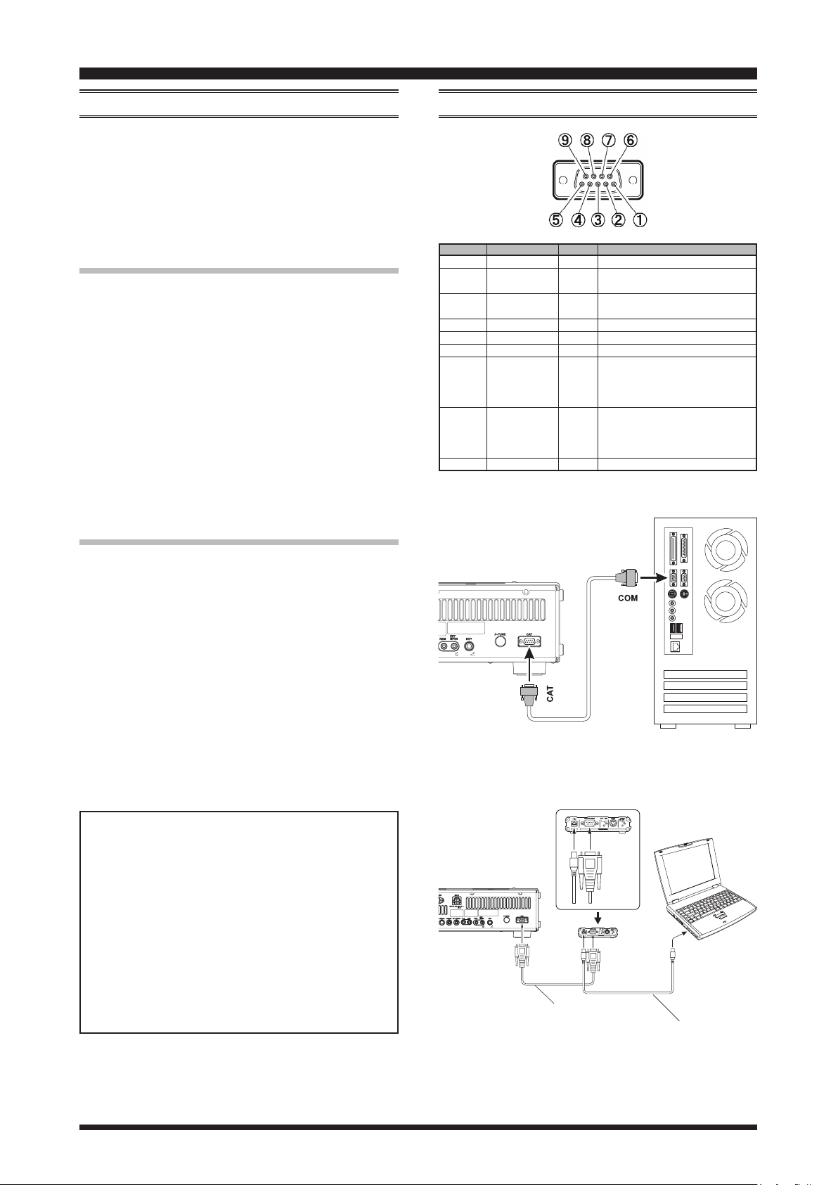
Using the RS-232C Cable
The
FT
DX
series has a built-in level converter, al-
1200
lowing direct connection from the rear-panel CAT jack
to the serial port of your computer without the need of
any external boxes.
You will need a serial cable for connection to the RS232C (serial or COM port) connector on your computer.
Purchase a standard serial cable (not the so-called “null
modem” type), ensuring it has the correct gender and
number of pins (some serial COM port connectors use a
9-pin rather than 25-pin conguration). If your computer
uses a custom connector, you may have to construct the
cable. In this case, refer to the technical documentation
supplied with your computer for correct data connection.
(Refer to gure 1)
pin nO.
COnneCTiOn
pin nAme
N/A
SERIAL OUT
SERIAL IN
N/A
GND
N/A
RTS
CTS
N/A
I/O
--Outputs the Serial Data from the
Output
transceiver to the computer.
Input
Inputs the Serial Data from the
computer to the transceiver.
---
---
---
Input
When the computer is not ready
to receive data, this port goes
to “L” to inhibit the transmit data
from the transceiver.
Output
When the transceiver is not ready
to receive data, this port goes
to “L” to inhibit the transmit data
from the computer.
---
FunCTiOn
Signal Ground
Personal Computer
---
---
---
---
Using the USB Cable with SCU-17
(Refer to gure 2)
Install the virtual COM port driver on the personal
computer before using the SCU-17 USB interface unit.
Please see the USB Driver (Virtual COM Port Driver)
on the Yaesu Website for details refer to (http://www.
yaesu.com/) in the
: Do not connect the USB cable and SCU-17 to
Note
FT
DX
product les section.
1200
your personal computer until after the “virtual
COM port driver” installation is completed, because an incorrect driver may be installed.
The SCU-17 interface unit may be used for CAT control
of the transceiver with a computer via a USB connection. You will need a USB cable to connect to the USB
jack on your computer.
YAESU MUSEN does not produce CAT System
operating software due to the wide variety of personal computers and operating systems in use today.
However, the information provided in this chapter
explains the serial data structure and opcodes used
by the CAT system. This information, along with
the short programming examples, is intended to help
you start writing programs on your own. As you
become more familiar with CAT operation, you can
customize programs for your operating needs and
utilize the full operating potential of this system.
DX
FT
1200
RS-232C “Straight” Cable
FT
1200
DX
RS-232C Cable
(Supplied w/SCU-17)
F
IGURE
1
Personal Computer
SCU-17
USB Cable
(Supplied w/SCU-17)
2
F
IGURE
FTDX1200 CAT Operation Manual1

CAT
(CompuTer Aided TrAnsCeiver
Control Command
)
operATion
A computer control command is composed of an alphabetical command, various parameters, and the terminator
that signals the end of the control command.
Example: Set the VFO-A frequency to 14.250000 MHz.
FA 14250000 ;
Command Parameter Terminator
There are three commands for the
below:
command: Set a particular condition
Set
command: Reads an answer
Read
Answer
For example, note the following case of the FA command (Set the VFO-A frequency):
To set the VFO-A frequency to 14.250000 MHz, the
following command is sent from the computer to the
transceiver:
“
To read the VFO-A frequency, the following com-
mand is sent from the computer to the transceiver:
“
When the Read command above has been sent, the
following command is returned to the computer:
“FA14250000;
command: Transmits a condition
FA14250000;
” (Read command)
FA;
” (Set command)
” (Answer command)
Ft
dX
(to the
(from the
(from the
1200
FtdX1200
FtdX1200
FtdX1200
as shown
Alphabetical Commands
A command consists of 2 alphabetical characters.
You may use either lower or upper case characters. The
commands available for this transceiver are listed in the
“PC Control Command Tables” on the following pages.
Parameters
Parameters are used to specify information necessary to
implement the desired command.
The parameters to be used for each command are predetermined. The number of digits assigned to each
parameter is also predetermined. Refer to the “Control
Command List” and the “Control Command Tables” to
congure the appropriate parameters.
When configuring parameters, be careful not to make
the following mistakes.
)
)
)
For example,
when the correct parameter is “
IS01000;
Not enough parameters specied (No direction (+)
given for the IF shift)
IS0+100;
Not enough digits (Only three frequency digits
given)
IS0_+_1000;
Unnecessary characters between parameters
IS0+10000;
Too many digits (Five frequency digits given)
Note: If a particular parameter is not applicable to the
, the parameter digits should be lled using
1200
Ft
dX
any character except the ASCII control codes (00 to
1Fh) and the terminator (;).
IS0+1000
” (IF SHIFT):
Terminator
To signal the end of a command, it is necessary to use
a semicolon (;). The digit where this special character
must appear differs depending on the command used.
FTDX1200 CAT Operation Manual2

CAT
(CompuTer Aided TrAnsCeiver
)
operATion
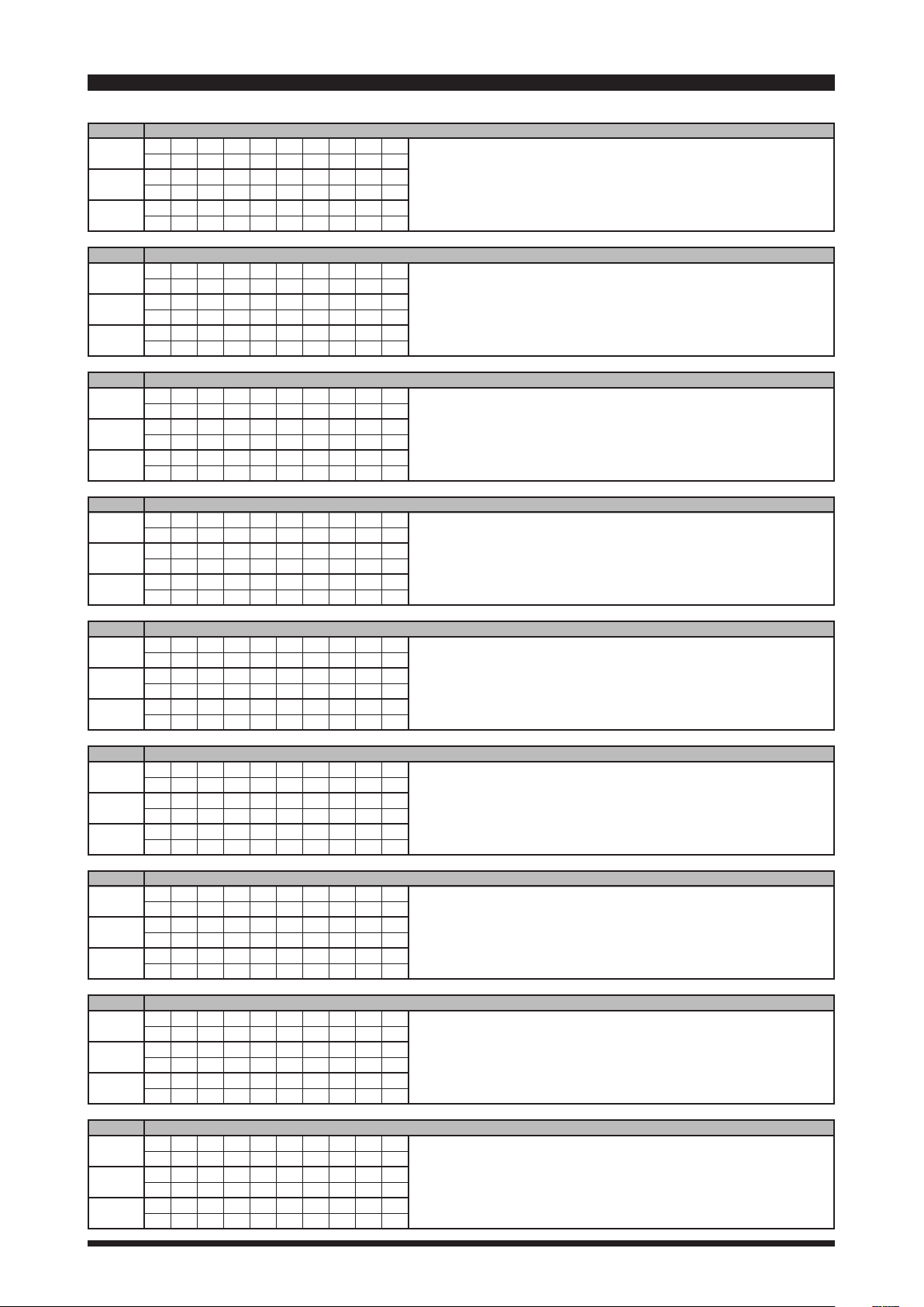
Command Set Read anS.
AB
VFO-A TO VFO-B
AC
ANTENNA TUNER CONTROL
AG
AF GAIN
AI
AUTO INFORMATION
AM
VFO-A TO MEMORY CHANNEL
AN
ANTENNA NUMBER
BA
VFO-B TO VFO-A
BC
AUTO NOTCH
BD
BAND DOWN
BI
BREAK-IN
BP
MANUAL NOTCH
BS
BAND SELECT
BU
BAND UP
BY
BUSY
CH
CHANNEL UP/DOWN
CN
CTCSS NUMBER
CO
CONTOUR
CS
CW SPOT
CT
CTCSS
DA
DIMMER
DN
DOWN
DT
DATE AND TIME
ED
ENCORDER DOWN
EK
ENT KEY
EM
ENCODE MEMORY
EN
ENCODE
EU
ENCORDER UP
EX
MENU
FA
FREQUENCY VFO-A
FB
FREQUENCY VFO-B
FR
FUNCTION RX
FS
FAST STEP
FT
FUNCTION TX
GT
AGC FUNCTION
ID
IDENTIFICATION
IF
INFORMATION
IS
IF-SHIFT
KM
KEYER MEMORY
KP
KEY PITCH
KR
KEYER
KS
KEY SPEED
KY
CW KEYING
LK
LOCK
LM
LOAD MESSEGE
MA
MEMORY CHANNEL TO VFO-A
MC
MEMORY CHANNEL
MD
MODE
MG
MIC GAIN
ML
MONITOR LEVEL
MR
MEMORY READ
MS
METER SW
MW
MEMORY WRITE
MX
MOX SET
NA
NARROW
NB
NOISE BLANKER
NL
NOISE BLANKER LEVEL
NR
NOISE REDUCTION
OI
OPPOSITE BAND NFORMATION
OS
OFFSET (Repeater Shift)
PA
PRE-AMP (IPO)
Function ai
O
X
X
O
O
O
O
O
O
O
O
O
O
X
X
O
O
O
O
X
X
O
O
O
O
X
X
O
O
O
O
O
O
O
X
X
O
X
X
X
O
O
O
X
X
O
O
O
O
O
O
O
O
O
O
O
O
O
O
O
O
X
X
O
O
O
O
X
X
O
X
X
O
O
O
O
X
X
O
X
X
O
O
O
O
O
O
O
O
O
O
O
O
O
O
O
O
O
O
O
O
O
X
O
O
X
O
O
O
O
O
O
O
O
O
O
O
O
O
O
O
O
O
O
X
X
O
O
O
O
O
O
O
X
X
O
O
O
O
O
O
O
O
O
O
O
O
X
O
O
O
O
O
O
X
X
O
O
O
O
O
O
O
O
O
O
O
O
O
O
O
X
O
O
O
O
O
O
O
O
Command Set read anS.
PB
X
O
O
X
X
O
X
O
X
O
O
X
X
O
X
O
O
O
O
X
X
X
X
X
X
X
X
O
O
O
O
O
O
O
X
O
O
X
O
O
O
X
O
X
X
X
O
O
O
X
O
X
O
O
O
O
O
O
O
O
PLAY BACK
PC
POWER CONTROL
PL
SPEECH PROCESSOR LEVEL
PR
SPEECH PROCESSOR
PS
POWER SWITCH
QI
QMB STORE
QR
QMB RECALL
QS
QUICK SPLIT
RA
RF ATTENUATOR
RC
CLAR CLEAR
RD
CLAR DOWN
RF
ROOFING FILTER
RG
RF GAIN
RI
RADIO INFORMATION
RL
NOISE REDUCTION LEVEL
RM
READ METER
RO
ROTATOR
RS
RADIO STATUS
RT
CLAR
RU
CLAR UP
SC
SCAN
SD
SEMI BREAK-IN DELAY TIME
SF
SUB-DIAL FUNCTION
SH
WIDTH
SM
S METER
SQ
SQUELCH LEVEL
SV
SWAP VFO
TS
TXW
TX
TX SET
UL
UNLOCK
UP
UP
VD
VOX DELAY TIME
VF
uTUNE FILTER
VG
VOX GAIN
VM
[V/M] KEY FUNCTION
VS
VFO SELECT
VX
VOX
XT
TX CLAR
ZI
ZERO IN
FunCtion ai
O
O
O
X
O
O
O
O
O
O
O
O
O
O
O
O
O
O
O
X
O
X
X
X
O
X
X
X
O
X
X
X
O
O
O
O
O
X
X
X
O
X
X
X
O
O
O
O
O
O
O
O
X
O
O
O
O
O
O
O
X
O
O
O
O
O
O
X
X
O
O
O
O
O
O
O
O
X
X
X
O
O
O
O
O
O
O
O
O
O
O
O
O
O
O
O
X
O
O
O
O
O
O
O
O
X
X
X
O
O
O
O
O
O
O
O
X
O
O
O
O
X
X
X
O
O
O
O
O
O
O
O
O
O
O
O
O
X
X
X
O
O
O
O
O
O
O
O
O
O
O
O
O
X
X
X
FTDX1200 CAT Operation Manual3
CAT
(CompuTer Aided TrAnsCeiver
)
operATion
AB VFO-A TO VFO-B
Set
A B ;
Read
Answer
AC ANTENNA TUNER CONTROL
Set
A C P1 P2 P3 ;
Read
A C ;
Answer
A C P1 P2 P3 ;
AG AF GAIN
Set
A G P1 P2 P2 P2 ;
Read
A G P1 ;
Answer
A G P1 P2 P2 P2 ;
AI AUTO INFORMATION
Set
A I P1 ;
Read
A I ;
Answer
A I P1 ;
1 2 3 4 5 6 7 8 9 10
1 2 3 4 5 6 7 8 9 10
1 2 3 4 5 6 7 8 9 10
1 2 3 4 5 6 7 8 9 10
1 2 3 4 5 6 7 8 9 10
1 2 3 4 5 6 7 8 9 10
1 2 3 4 5 6 7 8 9 10
1 2 3 4 5 6 7 8 9 10
1 2 3 4 5 6 7 8 9 10
1 2 3 4 5 6 7 8 9 10
1 2 3 4 5 6 7 8 9 10
1 2 3 4 5 6 7 8 9 10
P1 0: Fixed P3 0: Tuner “OFF”
P2 0: Fixed 1: Tuner “ON”
2: Tuning Start
P1 0: Fixed
P2 000 - 255
P1 0: Auto Information “OFF”
1: Auto Information “ON”
This parameter is set to “0” (OFF) automatically when the transceiver is turned “OFF”.
AM VFO-A TO MEMORY CHANNEL
Set
A M ;
Read
Answer
AN ANTENNA NUMBER
Set
A N P1 P2 ;
Read
A N P1 ;
Answer
A N P1 P3 P4 ;
BA VFO-B TO VFO-A
Set
B A ;
Read
Answer
BC AUTO NOTCH
Set
B C P1 P2 ;
Read
B C P1 ;
Answer
B C P1 P2 ;
1 2 3 4 5 6 7 8 9 10
1 2 3 4 5 6 7 8 9 10
1 2 3 4 5 6 7 8 9 10
1 2 3 4 5 6 7 8 9 10
1 2 3 4 5 6 7 8 9 10
1 2 3 4 5 6 7 8 9 10
1 2 3 4 5 6 7 8 9 10
1 2 3 4 5 6 7 8 9 10
1 2 3 4 5 6 7 8 9 10
1 2 3 4 5 6 7 8 9 10
1 2 3 4 5 6 7 8 9 10
1 2 3 4 5 6 7 8 9 10
P1 0: Fixed
P2 1: ANT “1”
2: ANT “2”
P3 1: ANT “1”
2: ANT “2”
P4 0: Fixed
P1 0:Fixed
P2 0: Auto Notch “OFF”
1: Auto Notch “ON”
BD BAND DOWN
Set
B D P1 ;
Read
Answer
1 2 3 4 5 6 7 8 9 10
1 2 3 4 5 6 7 8 9 10
1 2 3 4 5 6 7 8 9 10
P1 0: Fixed
FTDX1200 CAT Operation Manual4

CAT
(CompuTer Aided TrAnsCeiver
)
operATion
BI BREAK-IN
Set
1 2 3 4 5 6 7 8 9 10
B I P1 ;
Read
1 2 3 4 5 6 7 8 9 10
B I ;
Answer
1 2 3 4 5 6 7 8 9 10
B I P1 ;
BP MANUAL NOTCH
Set
1 2 3 4 5 6 7 8 9 10
B P P1 P2 P3 P3 P3 ;
Read
1 2 3 4 5 6 7 8 9 10
B P P1 P2 ;
Answer
1 2 3 4 5 6 7 8 9 10
B P P1 P2 P3 P3 P3 ;
BS BAND SELECT
Set
1 2 3 4 5 6 7 8 9 10
B S P1 P1 ;
Read
1 2 3 4 5 6 7 8 9 10
Answer
1 2 3 4 5 6 7 8 9 10
BU BAND UP
Set
1 2 3 4 5 6 7 8 9 10
B U P1 ;
Read
1 2 3 4 5 6 7 8 9 10
Answer
1 2 3 4 5 6 7 8 9 10
P1 0: Break-in “OFF”
1: Break-in “ON”
P1 0:Fixed
P2 0: Manual NOTCH “ON/OFF”
1: Manual NOTCH LEVEL
P1 00: 1.8 MHz 06: 18 MHz
01: 3.5 MHz 07: 21 MHz
02: - - - - 08: 24.5 MHz
03: 7 MHz 09: 28 MHz
04: 10 MHz 10: 50 MHz
05: 14 MHz 11: GEN
P1 0: Fixed
P3 P2=0
000: OFF
001: ON
P2=1
001 - 400 (NOTCH Frequency : x 10 Hz )
BY BUSY
Set
1 2 3 4 5 6 7 8 9 10
Read
1 2 3 4 5 6 7 8 9 10
B Y ;
Answer
1 2 3 4 5 6 7 8 9 10
B Y P1 P2 ;
CH CHANNEL UP/DOWN
Set
1 2 3 4 5 6 7 8 9 10
C H P1 ;
Read
1 2 3 4 5 6 7 8 9 10
Answer
1 2 3 4 5 6 7 8 9 10
CN CTCSS TONE FREQUENCY
Set
1 2 3 4 5 6 7 8 9 10
C N P1 P2 P2 ;
Read
1 2 3 4 5 6 7 8 9 10
C N P1 ;
Answer
1 2 3 4 5 6 7 8 9 10
C N P1 P2 P2 ;
CO CONTOUR
Set
1 2 3 4 5 6 7 8 9 10
C O P1 P2 P3 P3 ;
Read
1 2 3 4 5 6 7 8 9 10
C O P1 P2 ;
Answer
1 2 3 4 5 6 7 8 9 10
C O P1 P2 P3 P3 ;
P1 0: RX BUSY “OFF”
1: RX BUSY “ON”
P2 0: Fixed
P1 0: Memory Channel “UP”
1: Memory Channel “DOWN”
P1 0: Fixed
P2 0 - 49: Tone Frequency Number (See Table 1)
P1 0:Fixed
P2 0: CONTOUR/APF “ON/OFF”
1: CONTOUR FREQ
2: APF FREQ
P3 P2=000: CONTOUR/APF “OFF”
01: CONTOUR “ON”
02: APF “ON”
P2=1
01 - 40 (CONTOUR Frequency:100~4000Hz)
P2=2
00 - 50 (APF Frequency:-250~250Hz)
CS CW SPOT
Set
1 2 3 4 5 6 7 8 9 10
C S P1 ;
Read
1 2 3 4 5 6 7 8 9 10
C S ;
Answer
1 2 3 4 5 6 7 8 9 10
C S P1 ;
P1 0: OFF
1: ON
FTDX1200 CAT Operation Manual5
 Loading...