

Yaesu FTDX101D User Manual

CAT Operation Reference Manual
YAESU MUSEN CO., LTD.
CAT
① ② ③ ④ ⑤
⑧ ⑨⑦⑥
Personal Computer
Personal Computer
(Computer Aided Transceiver)
Operation
Overview
The CAT (Computer Aided Transceiver) System in the
FTDX101D
VFO, memory, and other settings such as dual-channel
memories and diversity reception using an external
personal computer. This allows multiple control
operations to be fully automated with single mouse clicks,
or keystroke operations on the computer keyboard.
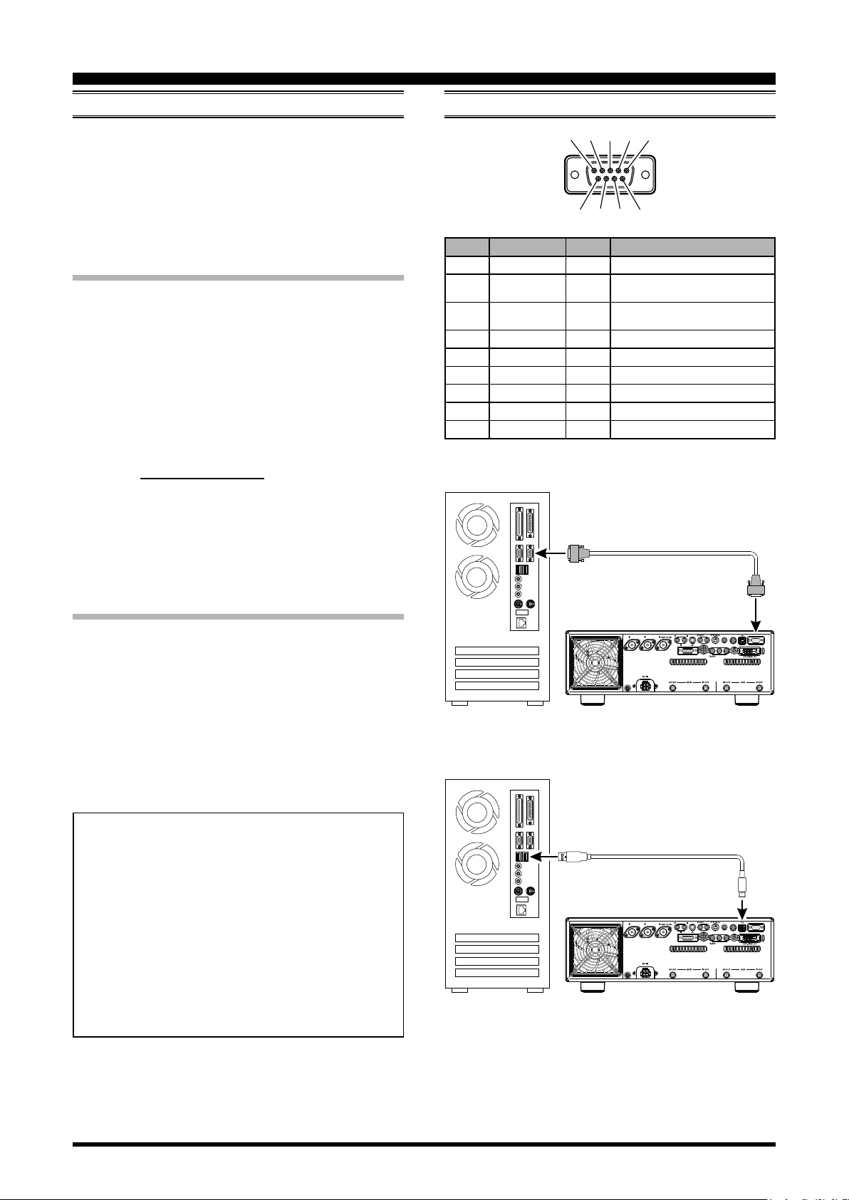
Using the RS-232C Cable
The
FTDX101D
allowing direct connection from the rear-panel RS-232C
jack to the serial port of your computer without the need
of any external boxes.
When using the RS-232C cable, set Menu item
[OPERATION SETTING] → [GENERAL] →
[TUNER/232C SELECT] to “RS232C”.
You will need a serial cable for connection to the RS232C (serial or COM port) connector on your computer.
Purchase a standard serial cable (not the so-called “null
modem” type), ensuring it has the correct gender and
number of pins (some serial COM port connectors use a
9-pin rather than 25-pin conguration). If your computer
uses a custom connector, you may have to construct the
cable. In this case, refer to the technical documentation
supplied with your computer for correct data connection.
transceiver provides control of frequency,
(Refer to gure 1)
transceiver has a built-in level converter,
Connection
Pin No. Pin Name I/O Function
N/A --- ---
SERIAL OUT Output
SERIAL IN Input
N/A --- ---
GND --- Signal Ground
N/A --- ---
RTS --- ---
CTS --- ---
N/A --- ---
COM
Outputs the Serial Data from the
transceiver to the computer.
Inputs the Serial Data from the
computer to the transceiver.
RS-232C “Straight” Cable
Using the USB Cable
Note
The
UART Bridge, allowing direct connection from the rearpanel USB jack to the USB jack of your computer without
the need of any external boxes.
You will need a USB cable to connect to the USB jack on
your computer.
(Refer to gure 2)
: A USB driver is required for remote control from
a computer. Download the driver from the Yaesu
website (http://www.yaesu.com).
FTDX101D
transceiver has a built-in USB to Dual
YAESU MUSEN does not produce CAT System
operating software due to the wide variety of personal computers and operating systems in use today.
However, the information provided in this chapter
explains the serial data structure and opcodes used
by the CAT system. This information, along with the
short programming examples, is intended to help you
start writing programs on your own. As you become
more familiar with CAT operation, you can customize programs for your operating needs and utilize the
full operating potential of this system.
FTDX101D
Figure 1
USB
FTDX101D
Figure 2
ANT 1 ANT 2
GND
ANT 1 ANT 2
GND
USB Cable
EXT SPKR KEY
A B
EXT SPKR KEY
A B
LINEAR
LINEAR
RS-232C
METER
REM
PTT
+13.8V
ACC TUNER
METER
REM
PTT
+13.8V
ACC TUNER
EXT ALC RS-232C
USB
EXT ALC RS-232C
1

CAT
(Computer Aided Transceiver)
Control Command
Operation
A computer control command is composed of an alphabetical command, various parameters, and the terminator
that signals the end of the control command.
Example: Set the MAIN Band frequency to 14.250000
MHz.
FA 014250000 ;
Command Parameter Terminator
There are three commands for the
below:
command: Set a particular condition
Set
command: Reads an answer
Read
Answer
For example, note the following case of the FA command
(Set the MAIN Band frequency):
To set the MAIN Band frequency to 14.250000 MHz,
the following command is sent from the computer to
the transceiver:
“
To read the MAIN Band frequency, the following
command is sent from the computer to the transceiver:
“
When the Read command above has been sent, the
following command is returned to the computer:
“FA014250000;
command: Transmits a condition
FA014250000;
” (Read command)
FA;
” (Set command)
” (Answer command)
FTDX101D
(to the
(from the
(from the
as shown
FTDX101D
FTDX101D
FTDX101D
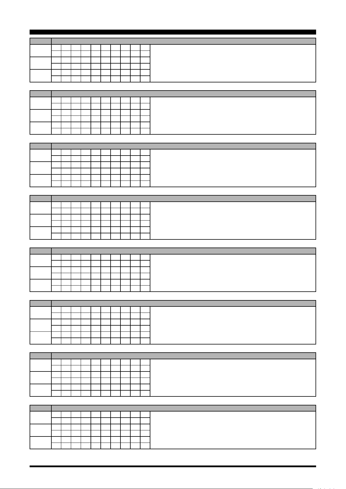
Alphabetical Commands
A command consists of 2 alphabetical characters.
You may use either lower or upper case characters. The
commands available for this transceiver are listed in the
“PC Control Command Tables” on the following pages.
Parameters
Parameters are used to specify information necessary to
implement the desired command.
The parameters to be used for each command are predetermined. The number of digits assigned to each parame-
ter is also predetermined. Refer to the “Control Command
List” and the “Control Command Tables” to configure
the appropriate parameters.
When conguring parameters, be careful not to make the
following mistakes.
For example,
)
)
)
when the correct parameter is “IS00+1000” (IF SHIFT):
IS001000;
Not enough parameters specied (No direction (+)
given for the IF shift)
IS00+100;
Not enough digits (Only three frequency digits
given)
IS00_+_1000;
Unnecessary characters between parameters
IS00+10000;
Too many digits (Five frequency digits given)
Note: If a particular parameter is not applicable to the
DX101D
character except the ASCII control codes (00 to 1Fh) and
the terminator (;).
, the parameter digits should be lled using any
FT-
Terminator
To signal the end of a command, it is necessary to use a
semicolon (;). The digit where this special character must
appear differs depending on the command used.
2

CAT
(Computer Aided Transceiver)
Operation
Command Function Set Read Ans. AI
AB
AC
AG AF GAIN O O O O
AI AUTO INFORMATION O O O X
AM
AN ANTENNA NUMBER O O O O
BA
BC AUTO NOTCH O O O O
BD BAND DOWN O X X X
BI BREAK-IN O O O O
BM
BP MANUAL NOTCH O O O O
BS BAND SELECT O X X X
BU BAND UP O X X X
BY BUSY X O O O
CH CHANNEL UP/DOWN O X X X
CN CTCSS/DCS NUMBER O O O O
CO CONTOUR O O O O
CS CW SPOT O O O O
CT CTCSS O O O O
DA DIMMER O O O X
DN DOWN O X X X
DT DATE AND TIME O O O X
ED ENCORDER DOWN O X X X
EM ENCODE MEMORY O O O X
EN ENCODE O X X X
EU ENCORDER UP O X X X
EX MENU O O O O
FA
FB
FN FINE TUNING O O O O
FS FAST STEP O O O O
FT FUNCTION TX O O O O
GT AGC FUNCTION O O O O
ID IDENTIFICATION X O O X
IF INFORMATION X O O O
IS IF-SHIFT O O O O
KM KEYER MEMORY O O O X
KP KEY PITCH O O O O
KR KEYER O O O O
KS KEY SPEED O O O O
KY CW KEYING O X X X
LK LOCK O O O O
LM LOAD MESSEGE O O O X
MA
MB
MC MEMORY CHANNEL O O O X
MD MODE O O O O
MG MIC GAIN O O O O
ML MONITOR LEVEL O O O O
MR MEMORY READ X O O X
MS METER SW O O O O
MT
MW MEMORY WRITE O X X X
MX MOX SET O O O O
NA NARROW O O O O
NB NOISE BLANKER O O O O
MAIN BAND TO SUB
Band
ANTENNA TUNER
CONTROL
MAIN BAND TO
MEMORY CHANNEL
SUB BAND TO MAIN
BAND
SUB BAND TO MEMORY
CHANNEL
FREQUENCY MAIN
BAND
FREQUENCY SUB
BAND
MEMORY CHANNEL TO
MAIN BAND
MEMORY CHANNEL TO
SUB BAND
MEMORY CHANNEL
WRITE/TAG
O X X X
O O O O
O X X X
O X X X
O X X X
O O O O
O O O O
O X X X
O X X X
O O O X
Command Function Set Read Ans. AI
NL NOISE BLANKER LEVEL O O O O
NR NOISE REDUCTION O O O O
OI
OS OFFSET (Repeater Shift) O O O O
PA PRE-AMP (IPO) O O O O
PB PLAY BACK O O O X
PC POWER CONTROL O O O O
PL
PR SPEECH PROCESSOR O O O O
PS POWER SWITCH O O O X
QI QMB STORE O X X X
QR QMB RECALL O X X X
QS QUICK SPLIT O X X X
RA RF ATTENUATOR O O O O
RC CLAR CLEAR O X X X
RD CLAR DOWN O X X X
RF ROOFING FILTER O O O O
RG RF GAIN O O O O
RI RADIO INFORMATION X O O O
RL
RM READ METER X O O O
RS RADIO STATUS X O O X
RT CLAR O O O O
RU CLAR UP O X X X
SC SCAN O O O O
SD
SF SUB DIAL O O O O
SH WIDTH O O O O
SM S METER X O O X
SQ SQUELCH LEVEL O O O O
ST SPLIT O O O O
SV SWAP VFO O X X X
SY SYNC O O O O
TX TX SET O O O O
UL UNLOCK X O O O
UP UP O X X X
VD VOX DELAY TIME O O O O
VG VOX GAIN O O O O
VM [V/M] KEY FUNCTION O X X X
VS VFO SELECT O O O O
VT VCT(VC TUNE) O O O O
VX VOX O O O O
XT TX CLAR O O O O
ZI ZERO IN O X X X
OPPOSITE BAND
NFORMATION
SPEECH PROCESSOR
LEVEL
NOISE REDUCTION
LEVEL
SEMI BREAK-IN DELAY
TIME
X O O O
O O O O
O O O O
O O O O
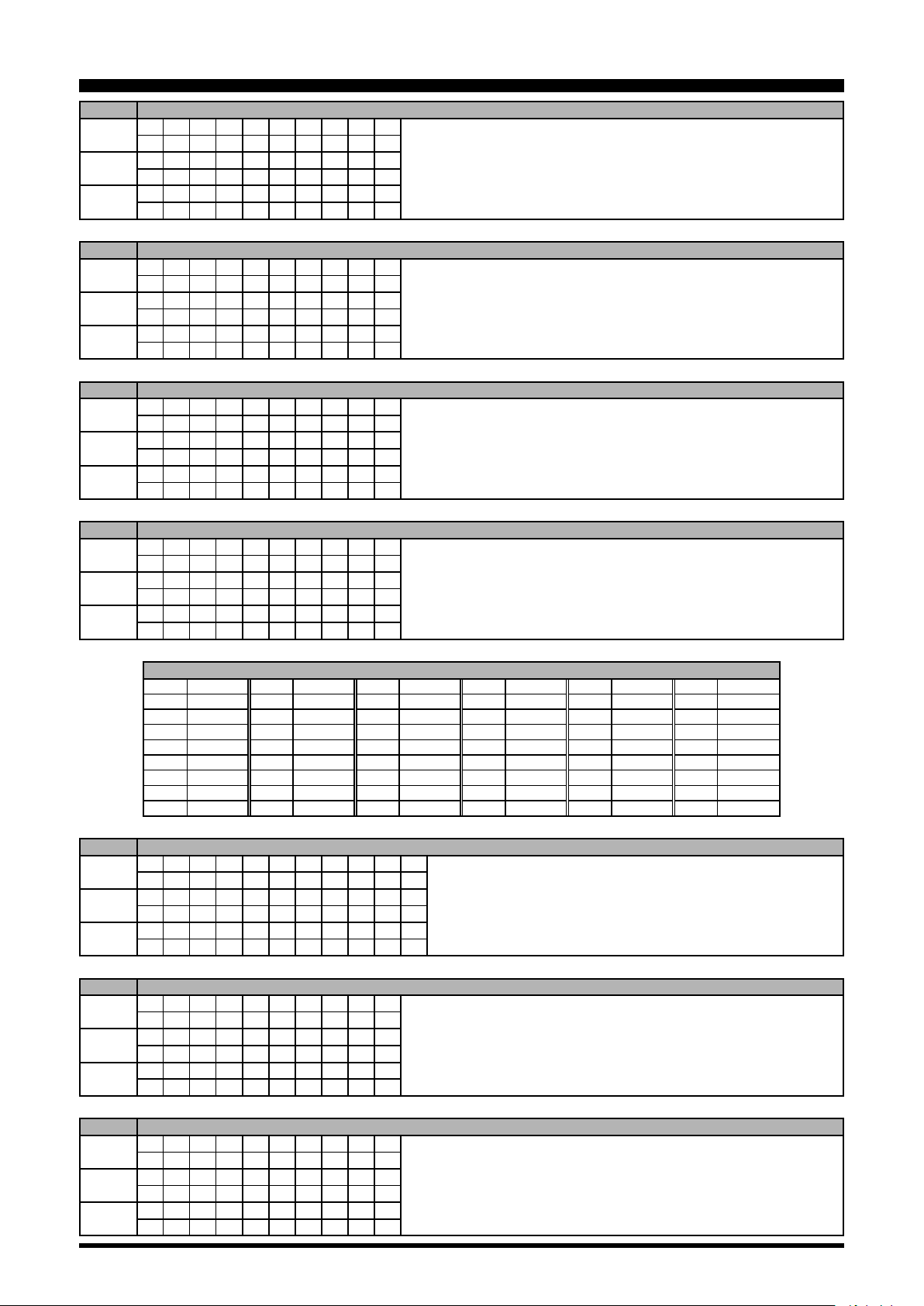
3

CAT
(Computer Aided Transceiver)
AB MAIN BAND TO SUB BAND
Set
Read
Answer
1 2 3 4 5 6 7 8 9 10
A B ;
1 2 3 4 5 6 7 8 9 10
1 2 3 4 5 6 7 8 9 10
AC ANTENNA TUNER CONTROL
Set
Read
Answer
1 2 3 4 5 6 7 8 9 10
A C P1 P2 P3 ;
1 2 3 4 5 6 7 8 9 10
A C ;
1 2 3 4 5 6 7 8 9 10
A C P1 P2 P3 ;
AG AF GAIN
Set
Read
Answer
1 2 3 4 5 6 7 8 9 10
A G P1 P2 P2 P2 ;
1 2 3 4 5 6 7 8 9 10
A G P1 ;
1 2 3 4 5 6 7 8 9 10
A G P1 P2 P2 P2 ;
Operation
P1 0: Fixed P3 0: Tuner “OFF”
P2 0: Fixed 1: Tuner “ON”
2: Tuning Start / Tuning Stop
P1 0: MAIN BAND
1: SUB BAND
P2 000 - 255
AI AUTO INFORMATION
Set
Read
Answer
1 2 3 4 5 6 7 8 9 10
A I P1 ;
1 2 3 4 5 6 7 8 9 10
A I ;
1 2 3 4 5 6 7 8 9 10
A I P1 ;
AM MAIN BAND TO MEMORY CHANNEL
Set
Read
Answer
1 2 3 4 5 6 7 8 9 10
A M ;
1 2 3 4 5 6 7 8 9 10
1 2 3 4 5 6 7 8 9 10
AN ANTENNA NUMBER
Set
Read
Answer
1 2 3 4 5 6 7 8 9 10
A N P1 P2 ;
1 2 3 4 5 6 7 8 9 10
A N P1 ;
1 2 3 4 5 6 7 8 9 10
A N P1 P2 P4 ;
BA SUB BAND TO MAIN BAND
Set
Read
Answer
1 2 3 4 5 6 7 8 9 10
B A ;
1 2 3 4 5 6 7 8 9 10
1 2 3 4 5 6 7 8 9 10
P1 0: Auto Information “OFF”
1: Auto Information “ON”
This parameter is set to “0” (OFF) automatically when the transceiver is turned “OFF”.
P1 0: MAIN BAND
1: SUB BAND
P2 1: ANT1
2: ANT2
3: ANT3
P4 0: Fixed
BC AUTO NOTCH
Set
Read
Answer
1 2 3 4 5 6 7 8 9 10
B C P1 P2 ;
1 2 3 4 5 6 7 8 9 10
B C P1 ;
1 2 3 4 5 6 7 8 9 10
B C P1 P2 ;
P1 0: MAIN BAND
1: SUB BAND
P2 0: Auto Notch “OFF”
1: Auto Notch “ON”
4
CAT
(Computer Aided Transceiver)
BD BAND DOWN
Set
Read
Answer
1 2 3 4 5 6 7 8 9 10
B D P1 ;
1 2 3 4 5 6 7 8 9 10
1 2 3 4 5 6 7 8 9 10
BI BREAK-IN
Set
Read
Answer
1 2 3 4 5 6 7 8 9 10
B I P1 ;
1 2 3 4 5 6 7 8 9 10
B I ;
1 2 3 4 5 6 7 8 9 10
B I P1 ;
BM SUB BAND TO MEMORY CHANNEL
Set
Read
Answer
1 2 3 4 5 6 7 8 9 10
B M ;
1 2 3 4 5 6 7 8 9 10
1 2 3 4 5 6 7 8 9 10
Operation
P1 0: MAIN BAND
1: SUB BAND
P1 0: Break-in “OFF”
1: Break-in “ON”
BP MANUAL NOTCH
Set
Read
Answer
1 2 3 4 5 6 7 8 9 10
B P P1 P2 P3 P3 P3 ;
1 2 3 4 5 6 7 8 9 10
B P P1 P2 ;
1 2 3 4 5 6 7 8 9 10
B P P1 P2 P3 P3 P3 ;
BS BAND SELECT
Set
Read
Answer
1 2 3 4 5 6 7 8 9 10
B S P1 P1 ;
1 2 3 4 5 6 7 8 9 10
1 2 3 4 5 6 7 8 9 10
BU BAND UP
Set
Read
Answer
1 2 3 4 5 6 7 8 9 10
B U P1 ;
1 2 3 4 5 6 7 8 9 10
1 2 3 4 5 6 7 8 9 10
BY BUSY
Set
Read
Answer
1 2 3 4 5 6 7 8 9 10
1 2 3 4 5 6 7 8 9 10
B Y ;
1 2 3 4 5 6 7 8 9 10
B Y P1 P2 ;
P1 0: MAIN BAND P3 P2=0
1: SUB BAND 000: “OFF”
P2 0: Manual NOTCH “ON/OFF” 001: “ON”
1: Manual NOTCH LEVEL P2=1
001 - 320
(NOTCH Frequency : x 10 Hz )
P1 00: 1.8 MHz 06: 18 MHz 12: MW
01: 3.5 MHz 07: 21 MHz 13: 02: 5 MHz 08: 24.5 MHz 14: 03: 7 MHz 09: 28 MHz 15: 04: 10 MHz 10: 50 MHz 16: 05: 14 MHz 11: GEN 17: 70 MHz
P1 0: MAIN BAND
1: SUB BAND
P1 0: MAIN BAND RX BUSY “OFF”
1: MAIN BAND RX BUSY “ON”
P2 0: SUB BAND RX BUSY “OFF”
1: SUB BAND RX BUSY “ON”
CH CHANNEL UP/DOWN
Set
Read
Answer
1 2 3 4 5 6 7 8 9 10
C H P1 ;
1 2 3 4 5 6 7 8 9 10
1 2 3 4 5 6 7 8 9 10
P1 0: Memory Channel “UP”
1: Memory Channel “DOWN”
5
CAT
(Computer Aided Transceiver)
CN CTCSS TONE FREQUENCY
Set
Read
Answer
1 2 3 4 5 6 7 8 9 10
C N P1 P2 P3 P3 P3 ;
1 2 3 4 5 6 7 8 9 10
C N P1 P2 ;
1 2 3 4 5 6 7 8 9 10
C N P1 P2 P3 P3 P3 ;
CO CONTOUR
Set
Read
Answer
1 2 3 4 5 6 7 8 9 10
C O P1 P2 P3 P3 P3 P3 ;
1 2 3 4 5 6 7 8 9 10
C O P1 P2 ;
1 2 3 4 5 6 7 8 9 10
C O P1 P2 P3 P3 P3 P3 ;
CS CW SPOT
Set
Read
Answer
1 2 3 4 5 6 7 8 9 10
C S P1 ;
1 2 3 4 5 6 7 8 9 10
C S ;
1 2 3 4 5 6 7 8 9 10
C S P1 ;
Operation
P1 0: MAIN BAND
1: SUB BAND
P2 0: CTCSS
P3 000 - 049: Tone Frequency Number (See Table 1)
P1 0: MAIN BAND P3 P2=0 0000: CONTOUR “OFF”
1: SUB BAND 0001: CONTOUR “ON”
P2 0: CONTOUR “ON/OFF” P2=1 0010 - 3200
1: CONTOUR FREQ (CONTOUR Frequency:10 - 3200Hz)
2: APF “ON/OFF” P2=2 0000: APF “OFF”
3: APF FREQ 0001: APF “ON”
P2=3 0000 - 0050 (
P1 0: OFF
1: ON
APF Frequency
: -250 - 250 Hz )
CT CTCSS
Set
Read
Answer
1 2 3 4 5 6 7 8 9 10
C T P1 P2 ;
1 2 3 4 5 6 7 8 9 10
C T P1 ;
1 2 3 4 5 6 7 8 9 10
C T P1 P2 ;
000 67.0 Hz 009 91.5 Hz 018 123.0 Hz 027 162.2 Hz 036 189.9 Hz 045 229.1 Hz
001 69.3 Hz 010 94.8 Hz 019 127.3 Hz 028 165.5 Hz 037 192.8 Hz 046 233.6 Hz
002 71.9 Hz 011 97.4 Hz 020 131.8 Hz 029 167.9 Hz 038 196.6 Hz 047 241.8 Hz
003 74.4 Hz 012 100.0 Hz 021 136.5 Hz 030 171.3 Hz 039 199.5 Hz 048 250.3 Hz
004 77.0 Hz 013 103.5 Hz 022 141.3 Hz 031 173.8 Hz 040 203.5 Hz 049 254.1 Hz
005 79.7 Hz 014 107.2 Hz 023 146.2 Hz 032 177.3 Hz 041 206.5 Hz - 006 82.5 Hz 015 110.9 Hz 024 151.4 Hz 033 179.9 Hz 042 210.7 Hz - 007 85.4 Hz 016 114.8 Hz 025 156.7 Hz 034 183.5 Hz 043 218.1 Hz - 008 88.5 Hz 017 118.8 Hz 026 159.8 Hz 035 186.2 Hz 044 225.7 Hz - -
DA DIMMER
Set
Read
Answer
1 2 3 4 5 6 7 8 9 10 11
D A P1 P1 P2 P2 P3 P3 P4 P4 ;
1 2 3 4 5 6 7 8 9 10 11
D A ;
1 2 3 4 5 6 7 8 9 10 11
D A P1 P1 P2 P2 P3 P3 P4 P4 ;
P1 0: MAIN BAND
1: SUB BAND
P2 0: CTCSS “OFF”
1: CTCSS ENC/DEC
2: CTCSS ENC
Table 1 (CTCSS Tone Chart)
P1 00: Fixed
P2 00: Fixed
P3 00 - 20:
P4 00 - 20: LED Indicators Brightness Level
TFT Display Brightness Level
DN MIC DWN
Set
Read
Answer
1 2 3 4 5 6 7 8 9 10
D N ;
1 2 3 4 5 6 7 8 9 10
1 2 3 4 5 6 7 8 9 10
DT DATE AND TIME
Set
Read
Answer
1 2 3 4 5 6 7
D T P1 P2 P2 P2 P2
1 2 3 4 5 6 7 8 9 10
D T P1 ;
1 2 3 4 5 6 7
D T P1 P2 P2 P2 P2
~
~
~
~
n-1 n
P2 ;
n-1 n
P2 ;
P1 0: Date
1: Time (UTC)
P2 P1=0 yyyymmdd (Year/Month/Date)
P1=1 hhmmss (Hour/Minute/Second, 24 hour time system)
6
 Loading...