


FT.757GX ]I
HF ALL MODE
COMPUTER
AIDED
GENERAL
TRANSCEIVER
DESCRIPTION
The FT-7s7GXII
?57GX,
most
trol
great
radio
bands,
Special new digital
steps,
loop scanning between
memory,
programming aùd more advanced
A
40dB
for minimizing
wídeband AM and narrowband
able RF amplifier and
dynamic
noíse blanking
able from narrow
with new developments
popular requests from
and computer-aided
versatility
bands, with
general
and
ten memory channels
and an improved
IF Notch filter
range
combines the
serìous
manufacturìng
and operator
100 watts of
coverage
features
interference during
20dB attenuator are
all frequencies
on
pulse
width can be set on
(ignition-type)
reception from
include operator selectable
which
dual VFOs
CAT
provided
is
its famous
finest features
in response
hf operators.
methods aÌlow the
convenience
PEP transmitter
store mode as well
(or
adjacent memories),
(Computer
control by
along
SSB,
IF
CW
filters
under a wide variety of
wide
to
of
to technological
on all
power
0.15 to 30
Aided
an external computer.
CW and ECSS reception
the front
("woodpecker")
Transceiver) System
wiih continuously
are included as
provided
predecessor,
advances
New advances
FT-757GXIl
modes and
oùtput
MHz.
mode-dependent
as fÎequency,
to optimize
condjtions,
panel,
blanking
on
a special
adjustabÌe
standard. A switch-
continuously
FT_
the
to the
and
in djgj!al
all hf amateur
the amateur
auto-resume
for simplified
AM
of
sensitivity
pulse
con
to offer
tunìng
clarìiier
lF Shift
signals.
and
while the
adjust
widths.
Full break-in
tronic keyer built
transmit/receive
wide variety of
QSK
svritching circuitry
QSK
provided
CW operation
in, as a standard
and non-QSK linea. amplifìers.
is
feature.
is
I
{'ith
provided
Yaesurs custorn designed
l\ew high voltage solid state
for direct t/r control
elec-
of
a
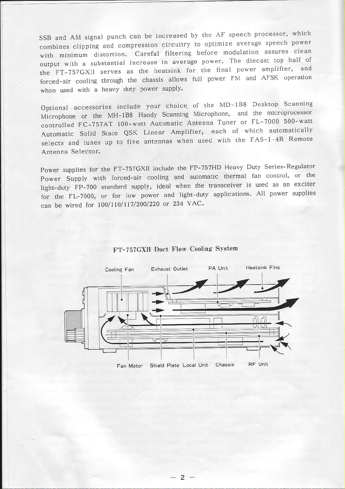
AM signal
and
SSB
combines
\ir'ith
output
the
minimurn
with
FT-757GXll
forced-air
when
used
clipping
distortion.
substantial
a
cooling
a heavy
with
punch can
compressìon
and
serves
as
through
duty
be
Careful
increase
heatsink
the
chassis
the
power supply'
increased
circuitry
fillering
in average
for the
allows
AF speech
the
by
to optimize
before
úodulation
power'
final
power
full
processor'
average
speecll
assures clean
The diecast
top
power amplifier'
FM and
AFSK
which
power
of
half
and
operation
Optional
accessories
Mìcrophone
controlled
Automatic
selects
Antenna
Power
Power
light-duty
for the
can
and tunes
Selector'
supplies
Suppiy
FL-7000,
wired îor
be
FP-700
MH_188
the
or
FC-75?AT
Solid
State
up to
the
for
with
forced-air
standard
for
or
l)o/ll1/117/200/220
include
Handy
100-watt
five
Linear
antennas
QSK
FT-757GXIÌ
supply,
power and ]i8ht
low
F'l'-757GXll
your
choice-
Scanning
Automatic
Amplifier,
include
cooling
and
ìdeal when
or 231
Dùct
Flo$
of
Microphone'
Antenna
when
the
used
FP-757HD
automatic
the
duty
vAC'
Cooling
lvlD
the
Tuner
each
of
with
Heavy
thermal
transceiver
applications.
S''rslem
lB8
and
or
whlch
the
ìs used
Desktop
microprocessor
the
FL-7000
autornatically
FAS-1
fan
AÌl
Series-
control'
power
Duty
Scanning
500-watt
Remote
4R
ReguÌator
the
or
as an exclter
supplies
Fan fvloto.
Shleld
Plate Loca
2
Unit
Chassls

SPECIFICATIONS
TRANSMITTER
l60m band
80m band
40m band
30m band
20m band
l?m band
l5m band
lzm band
l0ú band
Tuning steps
& CW: 10
SSB
AM: I kHz or 10
FM: 2.5 kHz or l0 kHz/step
Emission
types
LSB, USB
3Nd FM
(G3E)
SSB, CW &
sÌightly
AM: 25W Carrier
i.5 to 1.99999
3.5 to 3.99999
7.0
to
10.0 to 10,49999
14.0 to 14,49999
18.0 to 18.49999
21,0 to 21.49999
24.5 ta 24,99999
28.0 to
(selecrablel
Hz
or
(J3E)i
FM:
Cw
100W
Less
on
7.49999 MHz
29.99999 MHz
1 kHzlstep
kHzlstep
(A1A);
AM
PEPIDC, witl
10m band
MHz
MHz
MHz
MHz
MHz
MHz
MHz
(AsE)
Maximum
RF Output inpedance
FM
deúanon
15
kHz
50
ohms, unbalanced
{nominall
Microphone impedarìce
500 to 600 ohms
RECEIVER
150 kHz to 29.99999 MHz
Circuìt type
Triple-conversion superheterodyne
Clarifier range
unlimited
Sensitivity
(full
receiver range)
(for
iodB S+N/N, exc FM)
1s0-250kHz 250-s00kllz
SSB/CW l.0LrV 0.5uV 0.25uV
AM lùrv
FM:
o.suv for 12dB SINAD
(contjnuous)
.1uV
(above
è09!9
500kHz)
sookllz
1uV
SSB Carrier suppression
peak
betÈr than 40dB below
Unwanted sideband suppre.\sion
better than 50dB beÌow
(l
SpurÌous
better than 50dB beÌow
Audio response
Less
3rd
order
better than
(@l.1MHz,
Reference oscillator stability
betrer than
after l5 mìnute wa.mup at least 1.5W inro
Modulation
SSB/cw:
AM:
Fi\l: variable reacrance
tone)
kHz
radiatioD
-6dB
rhan
intermodùlation distortion
systems
earÌy stage
from 350 ro 2g00Hz
-35d8
100!v)
110ppm
active balanced
beÌow
lrom
(low
Ìevel)
ourplrl
(SSB) Image rejection
peak
ourpul
peak
ouLpur
peak
outplrt
,10'C
0 to
moduìator
Intemediate
47.060MH2, 8.2l5MHz,
better lhan
IF
rejection
beffèr rhàn 70dB
Selectivity { 6/ 6odB)
SSB, CW(W) & FSK 2.7/4.5 k{z
Dynamic range
better tha. 100d8
MaxinuÌn
Audio
audio
output
,1
to 16 ohms
frequencies
455kHz
70dB
frequencies)
{ali
CW(N) 600 Hzl1.3 kHz
AM 6/18 kHz
FM 15/30 kHz
(CW(N)
imp€dance
power
@l4MHz)
ourpur
4 ohms w/10o/' TllD
3
GENERAL
Supply voltage
!100/o
\DC
13.5
Pover @nsumption
Tramsitter
Dimensions
238 x 93
Weight
(approx)
5.2 kg
SpecifÌcalions
notice or oblì8ation.
out
(100W
(wHD)
x 238mm
(11.5
lb)
may be subject to change
ACCÉSSORIES
Supplied
outpul)
{without
2A
l9A
with
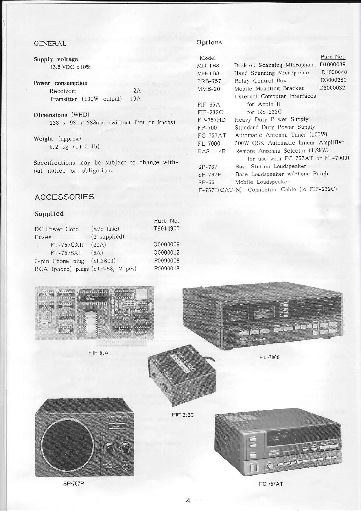
Options
Model
MD IB8
MH-IBE
FRB 757
MMB 20
FIF 65A
FIF-232C
FP-757HD
/00
fP
FC 757AT
FL 7000
FAS 1
SP-767
?6?P
SP
SP-55
E-?5711(CAT-N)
Desktop Scannlng
Hand Scanning
Relay
l\'lobiìeMountlngBracket
External Computer
Heavy
rtanda_d DrtY
Automatic
500W
,1R
Remote
Base
Base Loudspeaker
Mobrle
Control
for APPIe
RS 232C
for
Duty Power
Antenna
Automatic
QSK
Anten.a
lor use
Statlon
connecrion
wìth
LoudsPeaker
Lotdspèafe.
Mic.oPhone
Microphone
Box
ln|erfaces
tI
SUPPIY
PoEè-
suPDì)
Tuner
Linear Ampìifier
Selector
FC 757AT or
v/Phone
Cable
(to
Part
D1000039
D1000040
D3000280
D6000032
(100w)
(l.2kw,
FL-7000)
Patch
FlF 232C)
No.
DC Power Cord
Fuses
FT TsTGXrr
FT-7s7SXIj
3-pin
RCA
Phone
(phono)
pluC
pÌugs
(w/o
fuse)
(2
suppÌied)
(20A)
(64)
(SH3603)
(STP-58,
2
pcs)
T9014900
Q0000009
Q0000012
P0090008
P0090018
F)F-232C
FC
-757
Ar
L7 lq
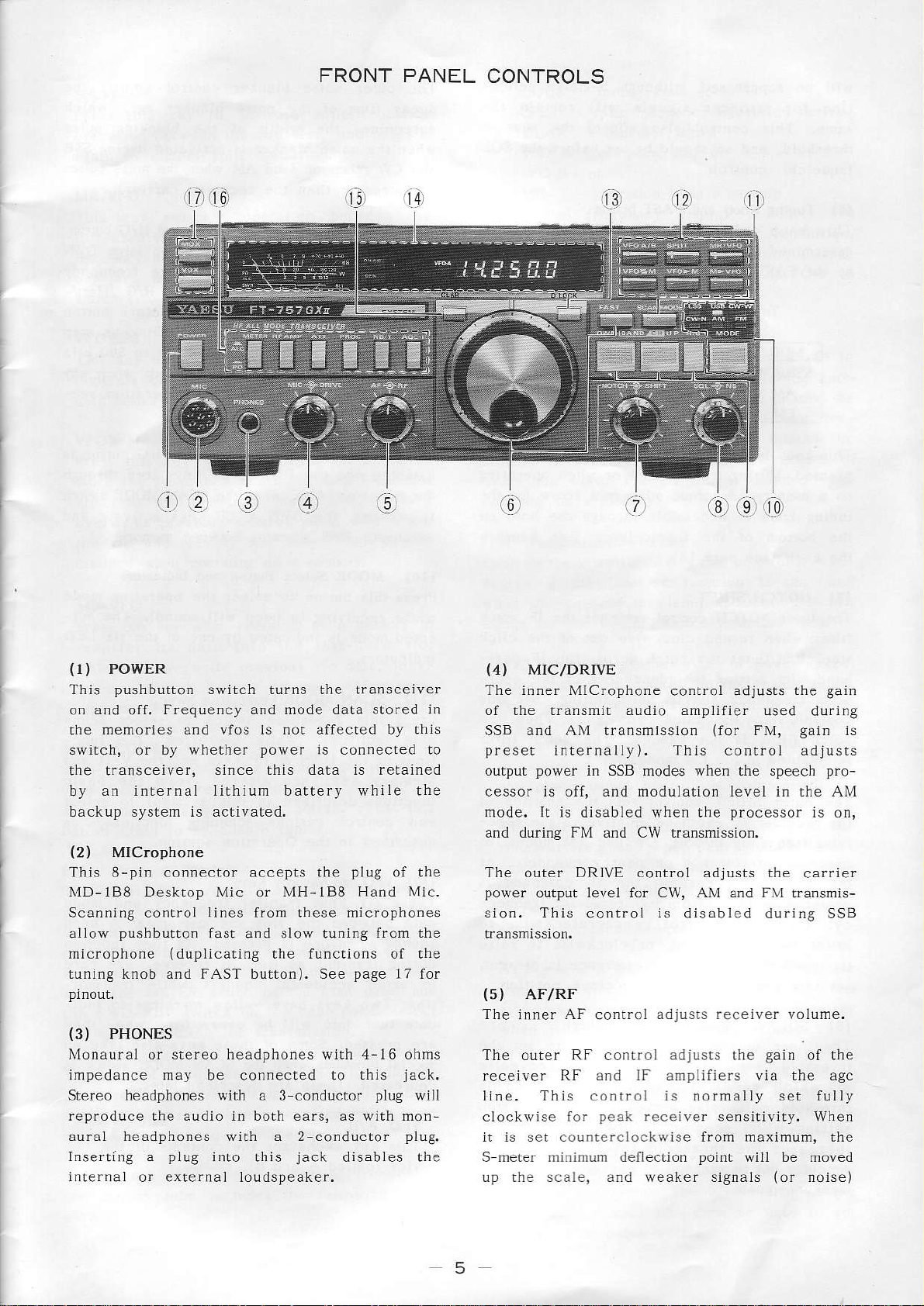
FRONT PANEL
CONTROLS
PowER
{r)
pushbutton
lhis
and
o.
rhe
swirch,
the transceiver,
by
backup system is activated.
(2)
This 8-pin co.nector accepts the
MD-188 Desktop Mic or MH-188 Hand MÌc.
Scanning controì
alloiv
microphone
tuning knob and FAST button). See
(3)
Monaural or stereo headphones with 4-t6 ohms
impedance
Stereo headphones with a 3 conductor
reproduce the audio in both ears, as with monauraÌ headphones with a 2-conductor
Inserting a
internaÌ
off.
memories and vfos is not affecred by thjs
by whether
or
an internal lithium battery while the
MlCrophone
pushbutton
PHONES
or exlernaì loudspeaker.
switch turns the lransceive.
Frequency and rnode data stored
power
since this dara is retalned
lines
from these microphones
fast
and slow tuning
(dupljcatjng
may be connected to this
pÌug
ìnto
this
is connecred ro
plug
of the
from the
the functions of the
page
l7 for
jack.
plug
plù9.
jack
dìsables the
in
wÌll
(4)
MIC/DRIVE
The inner MlCrophone
-ur
o. rh.
SSB and AM transmission
preset
output
cessor is off, and modulation level in the AM
nodr.
and during FM and CW transmission.
Th^ ort.r DRI\E
power
sion. This
{5)
lhe or
receiver
llne. This conlrol
clockwise tor
it is set counterclockwise from maximum, the
S meter rìinimum deflection
Lrp the scale, and weaker signals
power
outpùt level for CW, AM and FM rransmis-
AFIRF
'Tir
internally). This control adjrists
in SSB
Ir is
di hbt-d . en I
control
.or
h
Fr
RF and IF anrpliliers via rhe agc
peak
control adjusts
.Jdio anp
modes when
'
o dú.rii.
olt
is
disabled during SSB
dotu)1
rrol
js
normally set fully
.eceive.
point
itie-
{for
the speech
F
pro.ó.5of
ói
.
thc
sensjtivity. When
will be moved
r5-d
FM,
'h"
ér
Sajn
(or
the gain
du
gain
pro-
.arrie_
\olrme.
ol rl
noisel
r
o
8
is
c
-5
wìll be
rion
same.
suppressed,
for stronger
This control
threshold,
(squelch)
(6)
Tuning
This knob
determined
by the
FAST button:
Tuning
MODE
SSB/CW
AM
FM
although
signals
also
and so slould
co.troÌ.
Knob
tunes
the
by
FAST butto.
and
!he
operati.g
transcelver
Rates Ín kllzlstep
FAST ON
1 kHz
l0 kHz
kLIz
l0
S-meler
remai. rhe
will
affects the
be set before
at a fate
mode and
FAST OFF
Hz
10
kllz
2.5
defÌec-
squelch
SQL
the
selecled
'the
outer noise
decay time
determìnes
when the nojse
\\
L
and
stronger
are
BAND/CH
{9)
DurÍng
LIP keys are
and
bands,
GeneraÌ
determines
rhrough
general coverage
of these a.e
of lhis mànual
tìon
of the
the wid.h
-p.èpr
than the
reception with a
and for 500
coverage band
rhether the
the amateur
pfessed. See the Operation
blanker
noise bÌanker
of the bÌatking
blanker
'a
o
(D\{N
steps. A beep
is activated durÌng
\\4
d
received carrier).
& uP keys)
vfo, the two
used to
kHz steps.
bands only, or
for detalls.
control
q
èr
change frequency
step selector)
DWN & UP
adiusts the
agc,
|
.F 'o s
and H/C button
large D\\'l"l
The H/G
in 500 kHz
sou.ds when
whrch
pulse
SSB
Dllsps
(Ham/
butto.
keys step
any
sec-
the LOCK button
This knob is disabled
pressed, durÌng transmÌssÌón
a memory.
on
tuning knob
the bottom
the knob
(7)
NOTCH/SHIFT
The inner
filre.
stop, and tunes
band.
ating
conrrol inro rhe
.orch fìlter is
is
The
the receiver
iving frequency
suppress
the
centered
cy;
'o\^pr
the
set
(8)
The inner squeÌch
rfrp.ho
at rhich
th.eshoÌd
setting
Ìncreases
when turned clockwise
Its settjng
freque.cy
disabled
outer SHIFT
l2 o!clock
tufn this
rhp
passba.d. When no
this conlroÌ
SQL/NB
d
A torque adjusmenL
is accessible through
of the
(see
page
NOTCH controÌ
in the
IF
inrc.fe.ence
on the
lf
p1
(squeìch/Noise
è\él
recciver
poi.t
when scanni.g.
the rhreshold
,o
|
when
transceiver,
16).
actlvates lhe
the notch across
is independen.
and IF Shift setting.
clÌck stop
not needed.
l_M mode.
conlrol
!assband
in SSB,
posìtion the
(dÌsplayed)
control
òo-.d.
to the l2 orclock
control
or .r'on
also serves
. d ,o
r..p
seLs the
relatlve to
CW and
neàrby chanrers.
o.
counlerclockwise
or
interference
audio is
Clockwise
level,
b
when operating
or
screw
just
out
the
of lhe oper-
(olf)
The norch fiìler
AM modes, to
IF
receiving ireque.
.,o(au!.é
BÌanker)
is
used
g
srgn-
muled.
as the scan
'-l8ro I' d oisF o-
for úe
hoÌe on
the
benealh
IF notch
of the click
pass
IF
Ser rhis
when the
position
the rece
passband
ro ra:\r
prese.l,
is
position.
to se! lhe
nr
roisa
lhis
stoP
rotation
causing the
Ìs
of
Al
lo
is
H/G
When receiving
disabled
the
pressed, the DwN
is
oeJ
(10)
Press rhis
while
ected
(r1)
Press this 2
ning facjlities.
tions of Lhe DWN & UP
Memory keys a.e
luncrjons described
and
described
(12)
These
JarJ b-rq.p
sounds when ore
during transmil as well as
to avoid accidental changes whiìe rransmitting. lwo keys have
cate that data wlll be overwrirlcn when !hey
àre
special functìons when
c,pè.
and the
memories.
;\dr-
MODE Seìect
receìvjng
mode
SCAN MODE
control various scanning functions,
vFo and Memory Keys
six keys
pressed.
èa.
on a memory
DWN & UP
Also, when the
& UP keys activate
pv\
..
d.nirg o-ruF-r
Burton and Indicators
button to
js
indicated by one
posillo.
in the Operarion section.
rlrF
some of rhese keys aiso take on
.
Tl
selecl
(a
beep
Pushbunon Switch
swirch
While depressed, the func
altered
in this section) to select
transfer frequency and mode
v-o.
pressed.
ls
),eLlo1v
the SCA\ NIODE switch ls
\F
é-p la,flLaI dar.
the
keys step through
SCAN
the operating
will sound).
ol the
to select sca.-
keys and the VFO and
(from
TeTo
a d
As they funcllon
.eceive, use care
markings lo
button
MODE swÌtch
ìèîoric..
mode
The sel-
six
the basic
I
\.
A bèép
and
LED
as
indr-
VFO A/B
This key exchanges
vfos
(called
A and Bl.
rhc
co.tents of
the t{o
is
6
SPLIT
Press this key to
opera!ìon between
again ro cancel
MR/VFO
ThÌs key switches
last-used
frequency and
ory
which
vfo and the
are unaffected.
(vfo
or
sPlir oPeration.
mode data
nenlory) is currently
activate
the two
operation
last used
in the vfo and
The
split frequency
vfos, and
beLween
memory. The
disPlay
indicales
selected.
press
the
mem
LOCK - auning
SPLT - split
il
CLAR clarifier
VFO A operatjng vfo,
vFOB - or
MR
The digital frequency
operating frequency
When
operating
number
rlght of the frequency.
the
-
operation
on a memory,
(0
thru 9) is displayed
knob locked
frequency operation
active
or
is on a
display indicates
with 100
memory
Hz resolutÌon.
the memory channel
wìth
actlve
'CH'
the
Lo
VFOZ|.l
This key excharges
contents of
the last used
VFO>M
P.ess this
srore the frequency
vfo into the
ov€rwrite
the vfo and
ai.rbled
key when oPeratÌng
lasl used
previous memory data,
memory lhe
op^rd.inS
$l.pr
M>VFO
when operaung
Press this
lransfer
This will
r-è
irg
sìng
(13)
DLOCK
This button
vent accidental
shown
buúon
(14)
neier shows
The
units on the
either
and
mitter automatic
rèd pow-.
refrci
sion.
FwD
rhe
meter functio.
rhe
key
dala
its
overwrite
dra
vlo
key operation
this
disables
frequency
the display
on
again to
Meter &
The METER button
REV switch on
re enabìe
Dispray
uppermost
reLative
the frequency
vfo and lhe
mode data from
and
memory.
same.
à îemor\
on
into the
prevìous vfo
nerru"y de
wiÌl
tuning
the
changes.
when
tuninS.
relacive
power output
level control
pur
for
signal slrength
scaLe
(s$Rì
the lronr
on
lhe rear
rransmìssìon.
on
This key
a memorv
on
lasl-used
data,
'"np.
be on the
knob to
"LOCK"
active.
wnen
(PO),
g
du
pLìnel
and mode
last
a vfo to
thal
This wilÌ
and leave
is
Lo
vfo.
leav
A'èr Dre
vfo.
pre
Press this
S-
Ìn
recelvÌn8'
trans_
(ALC)
.-dn
panel
or
ri"-
and
serect
is
(15)
Press this
actjvate
and
receivef
quency. Press this button
change in
r,vhere
receiving on
{
Each of these
depressed
when undepressed
except for
-
CLAR
butlon
cla.ifier operarion.
D\4N & UP keys can
witho!t affecting
receiver frequency
you
were.
16)
Pushbutton
the ÌabelÌed
the NIETER swìtch
MhThR
functions of the
Power outpul
are in turn selecred
on the
this
and
RF AMP activates
recelver front end
imum
!lon the
increased immunity
signals on other frèquencies.
ATT
front end
avoid overload
when listening ro
"e
rear
switch ìs
power
receiver
pd's
whlle recejving
lhen be
again to cancel
The clarifìer
a memory.
Svitches
swilches
è.
rs
lunctions
panel.
output
gain.
RF ampìifi€r
a 20dB
circult, to reduce
has two
function
labeLled function
rhe
pr'hp
i. the depressed
of the
ALC or
meter during
(forward,
by the
ALC
when il ìs
the rf ampÌilier
when depressed, tor
ln the undepressed
to overload
"nc','u ia l'
rf
anplilier
verl st.ong slgnals.
on a vio
The luning
used to lune the
transmit fre-
the
retur. to
and
is dÌsabled when
positions; when
is
on,
descrjbed
potrétransmrssron.
or reverse)
FWD REV switcb
is indicated whe.
posÌtion,
undepressed,
is bl,!assed, for
l.om strong
sensitrvrry and
and mìxer
to
knob
the
and
is off,
next.
oL.p
Ìn lhe
màx
posi-
-'.Fr!p
rl
To the right of
glows red when
caror
stepping
At the left side of
the display
glows
is selected
lhe meter
t.ansmìtting,
Sreen
tube
when
jncìudes
the ON
a.d the cEN
general coverage
rllG bltton).
lhe
{via
the operating
the foÌlowing
iidicator
AIR
frequency,
i.di_
band
Ìnd:-
PROC acrìvates
increase average speech
tfansmìssjon, according
the coNlP LE\JEL conrol on
NB/T actilates rhe noise blarker
and ,à\l reception.
lower
the blanki.g
rìghr then be used ro set
the AF speech
pulse
7
processo.
power
to the level set by
the rear
fbr SSB, CW
The NB
wÌdth.
control
during
panel.
at the
to
SSB
AGC-F activates fast agc decay
(!r
dr a
naLs. When not depressed,
provided
strong s i8n a ls,
(17)
The transmjtter can be manually switched on
and off
SWR measurement and antenna
AM rF.óprion. to fd' iliréLF
and
rJring
MOX and VOX Pushbutton Swilches
by the MOX swirch.
or lrsrerinS
more
for
ro \c')
comfortable
time for SSB,
\.rnn; g
wédh
slow agc decay
recep!ion ol
Tìris is
tuning.
si8
useful
is
for
The VOX switch activates voice-actuated
$ansmit/receive
CW keying.
switch
transmìtter wilÌ be activated
into the micfophone. When finished speaking or
releasing the CW key
ver wjll be automarically
short delay, as set by the DELAY control on
is in
switching, and
In
AM & FM modes, when this
SSB,
the depressed
{Ìn
positio., the
just
CW node), the recei-
reactivated
serni
by
break in
speaking
after
a
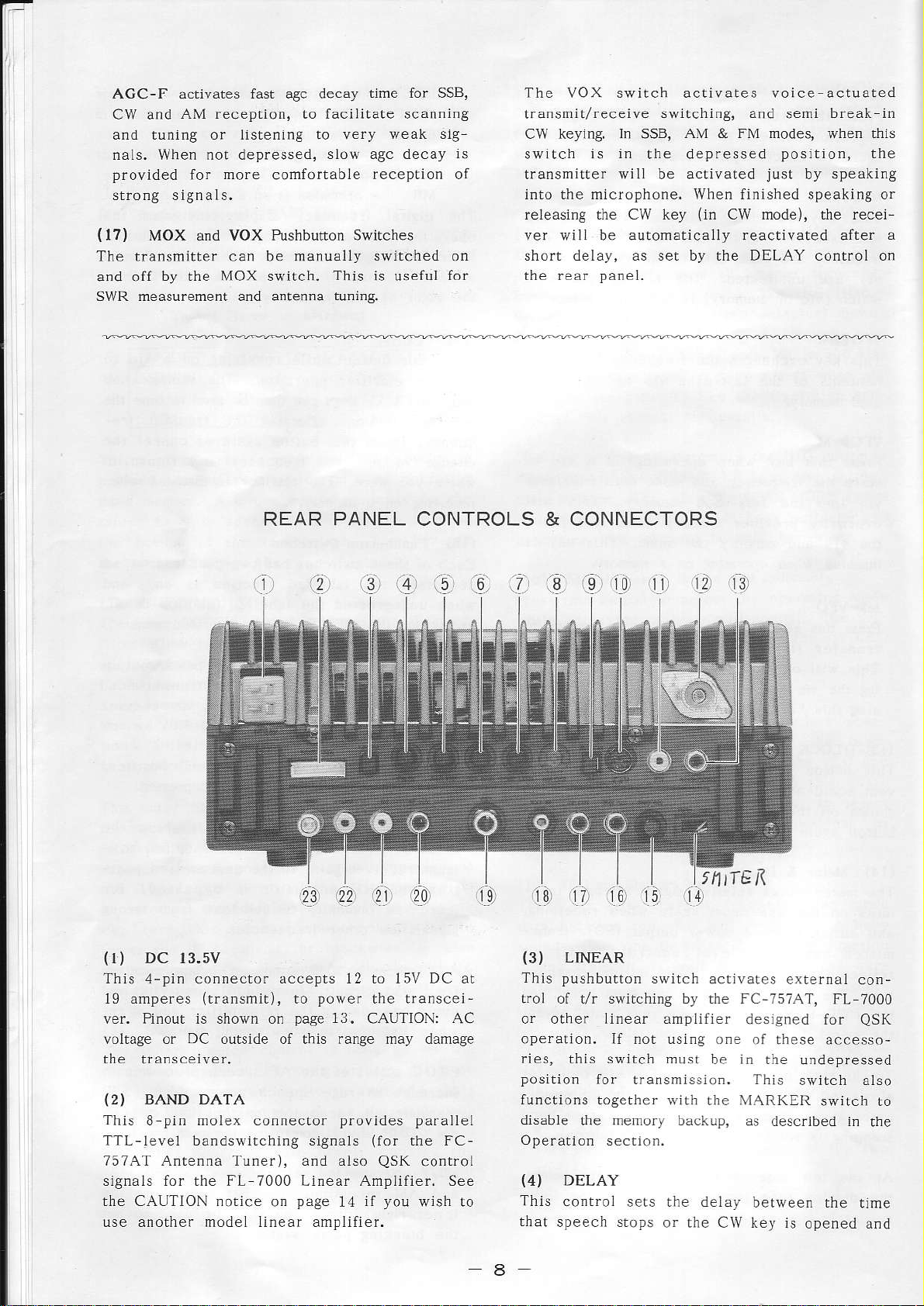
REAR
PANEL
CONTROLS & CONNECTORS
'.i:
.!..'.41
DC 13.5V
{r)
This 4-pi. connector accepts l2 to 15V DC at
l9 amperes
ver. Pinout is shown on
voltage or
the transceiver.
(2)
BAND DATA
This 8 pin
TTL-leve1 bandswitching signals
7574T Antenna Tunef), and also
signaLs for the FL 7000 Lìnear Amplifier. See
the CAUTÌON .otice
use another model linear anplifier.
(transmit),
DC
outside of this range may damage
molex connector
on
power
to
page
page
the transcei-
13.
CAUTION:
provides parallel
(for
QsK
you
ìl
14
.c_,
AC
rhe FC-
conÍol
wish to
ií.
11.
(3)
This pushbutton
troì of t/r sivirching by rhe FC-757AT,
or other linear amplifier
operation. If not using o.e
ries, this switch mùst
position
functions togerher
disable
Operation
(4)
This
that
..91
€',
LINEAR
for transmissìon. This
the memory backup, as
DELAY
controÌ
speech stops
Ll
switch activates
wìtì the MARKER
section.
sers rhe delay
or the CW key is
i?-ì
i9
tktTE
I
desìsned for
be in rhe
of these accesso-
described in
between the
'roì
e{rernai
FL 7000
undepressed
srvitch atso
swrLcn ro
opened and
con-
QSK
rhe
time
a

the tirne that
the VOX system
the front
(5)
ANTI TRIP
the receiver
is activated by lhe
panel.
This controÌ sets
receiver
an1pLifier
should be
key the
(6)
This control
fier
depends on
audio feedback
durìng
VOX
set so that speaker
transmitter,
GAIN
VOX
sets the
for VOX operaLion.
the microphone
characreristìcs of
(7)
COMP
This control
éucio
wlth lhe
sion
Operation section
Lhe
(8)
AM CAR
(recessed)
This
ratio of
LEVEL
sets the compression
!pèe.
.omprè\Lor arr.
processor
trimmer
transmìtted carrler
AM rransmission.
OperaLion sectìon.
the
(9)
MARKER
Set this
position
generator,
p..
the receìver.
not
pushbutton switch to the dePressed
to actìvate
which
,r 2itH/
produces
d'
When the callbration
needed, this siritch
ovorc inr--fé.è
lhls swirch aìso
functions in conjuncron
the LINEAR switch
as described
later.
is reactivated
the amount ol
applied to the
operarion.
audio does
gain
of the
The optimum seLting
used and the
the operator.
g
(PROC
switch) on See
for adjustmena,
potentiometer
to modulatio.
Adjuslmenl
ls described
the 25kHz
a carrier
.. rlè
l-Pqupn.\
should be olf
,.é { |lh norn-
to disabìe
the memo.y backup
when
swÌtch on
negalive
VOX
The level
nol
VOX anpli-
voice
level of
sSB
the
r:ì mr'
the
sets
ior
in
marker signal
at n1ultl
'ìrg^ or
signaì
is
(oul),
-'.
F!
io ,.
wrth
(12)
This type-M
system, antenna tuner
input. impedance requiremenl
balanced.
{PL
(I3)
This
a
dance
exrernalÌy adjusted
atorrs micropho.e,
output wirh the
{
This
forward or
during fansmission,
the fronl
ANT Coaxial
(SO-239) jack
Use onìy
pìug and 50 or 52-ohm coaxial
259)
PATCH/AFSK
phono
phonp pJr'h
jack
accepts
o- AF\K ronp
is 600 ohms, and the
same MIC
I4) FWD-REV
switch
selects meter indicatÌon of either
reverse relàtive rt
paneì
Jack
is for the antenna
or Ìinear amplÌfier
is
50 ohms'
properLy
a
matÌng type-M
cable.
transmitter input from
gererdror. lmDè-
ìevel should be
to match rhat of the oper-
producing
gain
the same
control setting.
power
power
ourput
when the METER swiLch on
ìs
ìn
the depressed
(PO)
un
positjon. Refer to the following description
the FWD SET control, and the description ol
of
SwP nFa\u'èré r lé OpF-arior sp' io].
(15)
Thìs
the metef for forward and reverse
during transmissìon.
FWD
SET
potentìometer
adjusts the sensitivity of
PO
funcrions
Adjust this conlrol for
full scale meter deflection ìvhile tra.smltting
a carrier wiah the
position,
FWD
meter in the
16) EXT ALC
{
This phono
level
lor
should
the
control volaage from a
l'F l
be be.leen
outer contact
REV positìon.
jack
dr ri
FwD-REV swirch ser to rhe
so that
SWR
can be
read
accepls transmìtter automatic
linear
-'
Fr
p\
iP. Thr "pp i-d \oÌ -gP
0 and
(chassis
-5V
DC, referenced to
ground).
ampljfier
on
the
(10)
cAT
jack
This 6
rhe seriaÌ dara
a4a A
ceìver
sectio. of
(ll)
This phono
pin
mini
lines from rhe
'
D
orvp,
from an external computer.
this maDual for details.
PTT
Jack
jack
line, for external
DIN
-_,
fo_
provides
.eceive/t.ansmiL control by
provides
.4nrrol
access to
access
microcompuler
rhc lrJ-\
of
See the CAT
the PTT
a lootswitch or other devlce. Connectlng
Lì.3
(chassjs
Maximurn
mA.
inner contact to the outer
ground)
open circLrit voltage
minimum cÌosed
activares the transmitter.
present is 13.5V, and
ci.cuit currenL is
contact
to
the
(I7)
This phono
AF OUT
jack
provides
consta.t
ìow-level
receiver audio, unaffected by rhe AF
control, for tape recording, digitaÌ demodulators capable of hlgh impedance input or an
external audio amplifier. Oùtput level is ap
proxlmately
(18)
'Ihis
EXT
1/8-ìnch 2-conductor mìni
provides
200mV
SP
ampÌifièd receiver output to
peak
(Erternal
ar 50 kllohms.
Speaker)
phone
drive
external 4- to 16-ohn Ìoudspeaker.
(
This ì inch 3-co.ductor
l9)
KEY
phone
jack
9
gaìn
jack
an
accepts
keyer
keyer, or a straighr
keyer is switched off).
shown on
DC
paddles
for rhe irternal
CW key
page
17. Open circuit vollage
a.d closed circuit
(when
Wjring connections are
current is 0.5 mA.
CAUTION: None of the ùree KEY
are connecled to chassìs
ground. DO NOT
nect the outer contact to chassis
electronic
the Ìnternal
+sV
is
jack
conracts
con-
grourd-
{21}
+8V
This phono
fof low
122)
This
mA for
tacl
power
+rs.sv
phono
poweri.g
is positive.
jack
provides
accessories.
jack
provides
accessories.
8V DC
at up to 100mA
The
center contact
13.5V DC at up to 500
The
cenrer con-
{20)
This
from an early
e)!clung a rfansverrer.
Poiver ìeveÌ
at 50 ohms.
RF OLIT
phono
jack
provides
stage
ìs approxjmately
low ievel
the transmitter, for
of
-6dBm
RF
(0.1
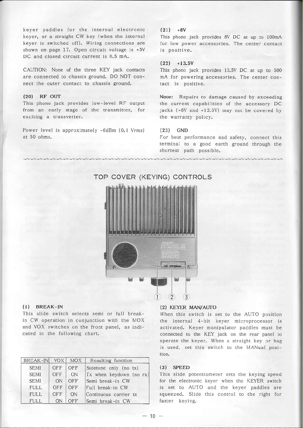
TOP COVER
oulpul
Vrms)
(KEYING)
Note: Repairs to
lhe current
jacks ("8V
the warranry
(23)
For
terminal to a
shortest
GND
best
capabiììties of the accessory DC
+13.5V)
and
policy.
perfo.mance
good
path possib
CONTROLS
damage caused by exceeding
may .or
and safety, connecr this
earth
le.
be covered by
ground
through
the
BREAK.IN
{I)
Thls slide switch seÌects semi
in
CW operation in conjunction
and VOX
cated in
BRTAK IN VOX MOX
SEl/II
SEMI
SE\fI
FULL
FULL
FULL
swìtches on the front
folÌowing
.he
chart,
ResuÌti.s functio.
OFF OFF
OFF ON
ON OFF
oFF I ON
oN I oFF
Sidetone only
Tx wheÍ keydown
Seni break-in Cw
Full
Continuous
Semi
break in CW
break-in
wìth lhe l\'1()x
(no
L\)
(no
rx)
carrler LÌ
CW
'.2
11.
{2)
When
llp
actìvated. Keyer manipulato.
connected to the KEY
operate the keyer. Whe. a straìght
ls used,
(3)
'Ihis
for rhe
ls ser
squeezed. Slìde this control to the right
faster
t0
rol
KEYER MAN/AUTO
this switch is set to Lhe AUTO
èr1.'
in
SPEED
slide
electronic ker-er when the KÈYER switch
to
kcying.
t
set this srvitch io rhe XlANual
poleftionerer
AUTaJ
-
bit
jack
and lhe keyer
I
r.t
on the rear
sers the keying speed
prn(é
paddìes
position
.o
musr be
faÌrcl
key or bug
posi
paddÌes
I.
ro
are
for
INSTALLATION
PRELIMINARY
Upon opening the
transceiver carefùlly
INSPECTION
packing
carton,
inspect the
for any signs of danage.
Check to ensure lhat all exposed controls and
switches move freely, and that the cabinet has
no
dents or
scratches. If
age, document
shipping company
materials for
BASE
STATION
possible
it
completely
ìrnmediarely. Save dìe
INSTALLATION
you
notice any damand
futu.e use.
contact the
packing
AC Power Supply
The FT-757GXIÌ requires a
to 15 volts
voice
Yaesu
alÌ of which
DC,
peaks.
offers
capable of
For base station insrallations,
a variety of AC
rnay
used vith AC line voltages
be
power
up to 20
power
source of i2
amperes on
sÌrpplies,
of 100, 110, 117, 200, 220 or 234 VAC.
Ho$,ever, before connectiDg any
the transceiver or
the supply is
AC line,
properly
ser up for the local
power
supply to
make certain that
ljne voltage, and that the correct fuse in
instaued.
The FP-757HD is a heavy
power
tion with full
supply capable of 50% duty cycle opera-
po\r'er
transmissions for up to
30 minutes at a tim€.
provided
an extra large internal heat-
over
duty series
Forced-ai.
regulator
eooling
is
sink. The FP-757HD requires a 6-amp fuse for
100, 110 or 117 VAC, or a 3-amp fuse fo! 200,
220 or 234 VA..
Potrèr
lranqformer
connections for lhe different
are shor/n on the next
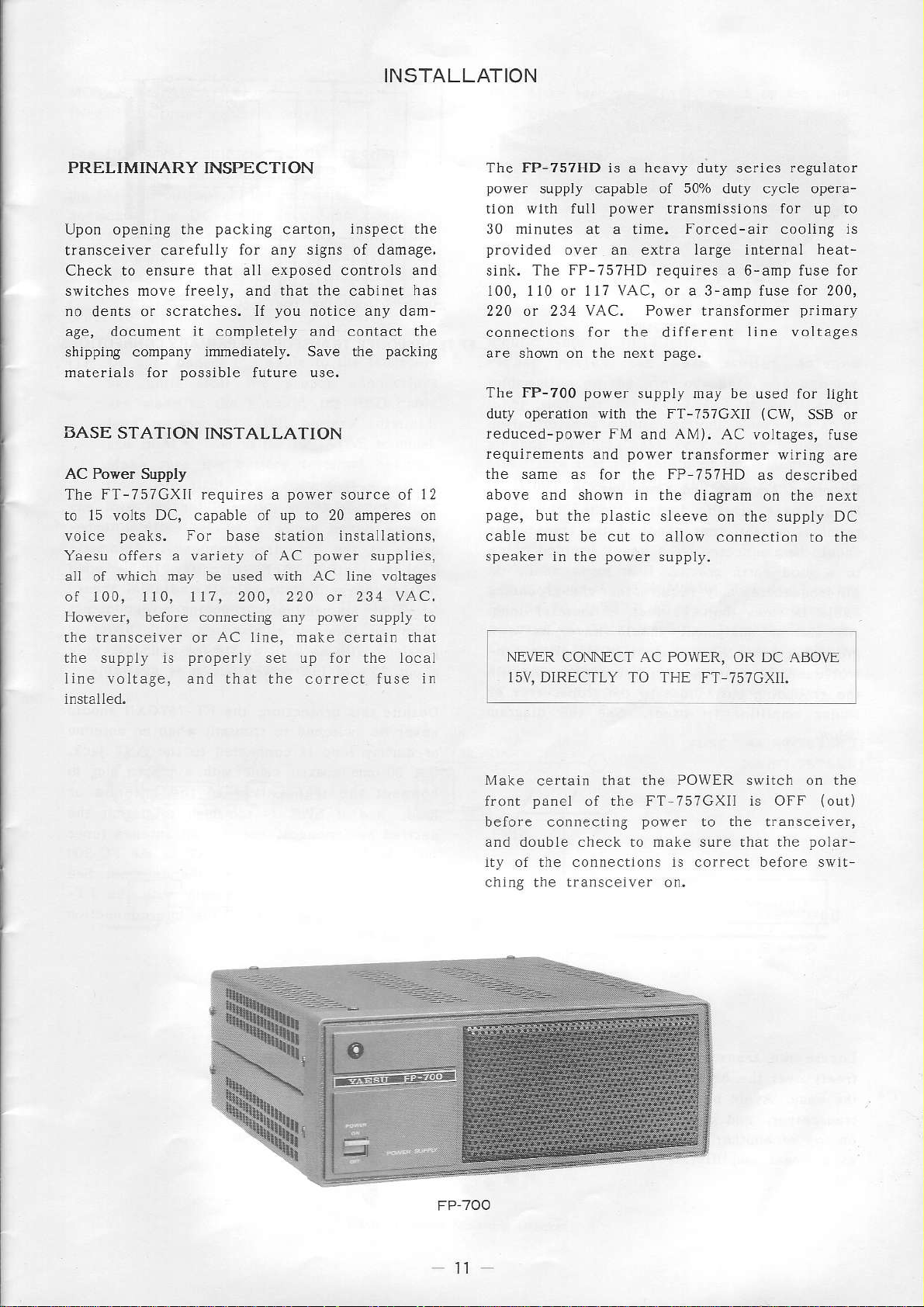
The FP-700 pover
duty
operation
with
reduced-power FM
reqìiirements and
the same
as for the
above and shown in
page,
but the
cable must
speaker in the
plastic
be cut to allo\r
power
pa8e.
supply may be
FT-757GXII
the
and AM). AC
power
transformer
FP
757HD
the diagram
sleeve on rhe supply DC
connecrion ro rhe
supply.
line voltages
primarJ
used for light
(CW,
SSB
or
voltages, fuse
wiring are
as described
the nexr
on
NE\ER CONNECT AC POWER, OR DC
15V, DIRECTLY TO
THE FT 75?GXIt.
Make
front
before connecling
aDd doúbte check to make sure that the
ity of the connections is correcr before swil-
chjng the transcelver on,
certain that the
panel
the FT-757GXÌI is OFF
of
POWER
power
switch
to the tra.sceiver,
on the
{out)
polar-

ffi
f
rr
t-
I
ll
tl-tf
Equipment
lf all
te
should
to a
all
cable
All station
grounding
troÌ
the
lÌnear
base
rin
un
be
good earth
frequencles
be
cables),
grounding
anrpÌifier
Location
connected
less
squipment
cable
and
slation
ground.
mav
ùan
(jndepe.denr of signal
connected
close
bus,
{if
FP.757HD
GroÙnding
inslalLations,
I ol
heavy
a
bv
perlornànce
Best
requÌre
10
used).
that
leer
shouid
à conmon
!o
thc
Lo
See
(3
the
rhP
'n
r'
braided
groundlng
the
meters)
the
ils own
or con-
point on
dragram
have
trans'eìver
GND
'è \F_
cabÌe
oo
long'
or
FP.757HD
POWER
The
antenna
dance
finaÌ
in !he
istors by
when
present.
about
Despile
never
or dummy
Use so-ohm
connecl
load,
desired
such
betveen
page 22
757GXll,
TRANSFORMER
FT-7;7GXII
sysrem
the operatjng
a!
protecrion
transmitter
automaticallv
jmPedance
a.
\lith a.
?50/o of
this
be swÌtched
and
performa.cc,
as the
full
prolection,
load
coaxiaL
lransceiver
!he
if SWR
automatic
transceiver
the
SWR
for
dnd
PNt[4ABY
is designed
having
is connecred
pages 11-16
a 50-ohm
frequencv
(AFP)
SNR
poser outpur
circuitfy
protect thc
to
reduci'g
misnatch
3:l Ior
ot
the
transmit
to
cabLe
measurement
with
too
is
connect
FC-757AT
a.d rhe
CONNECTIONS
anv
wrth
use
for
resistve
is
final
power outpur
(high
exarìple,
is avàilable.
FT-757GXll
when
the
to
proper
a
anlenna
an
or
anrennlì
wllh
anrenna
to the
high lo
for inter'Ónnection
rmpe-
ArirÒmarlc
included
tra's
SWR)
onLl
should
no anrenna
jack'
ANT
plug
or
pe'miL the
tuner
700
FC
the
See
FT
the
is
to
Locare
freeiy
!he
transcejver,
on
as
the
over
case.
top of
linear amPlilier.
a
transcerver
heatsink
the
Avold
anorher
and
PÌacing
do
not
heat
air
that
so
a.d u.def
anylhing
pÌace
generatìng
!he
can
and behind
top of
on
traùscelver
devìce
flow
Lhe
such
12
 Loading...