

Yaesu FT-2600M Operating Manual

144 MHZ BAND FM TRANSCEIVER
FT-2600M
OPERATING MANUAL
VERTEX STANDARD CO., LTD.
4-8-8 Nakameguro, Meguro-Ku, Tokyo 153-8644, Japan
VERTEX STANDARD
US Headquarters
17210 Edwards Rd., Cerritos, CA 90703, U.S.A.
International Division
8350 N.W. 52nd Terrace, Suite 201, Miami, FL 33166, U.S.A.
YAESU EUROPE B.V.
P.O. Box 75525, 1118 ZN Schiphol, The Netherlands
YAESU UK LTD.
Unit 12, Sun Valley Business Park, Winnall Close
Winchester, Hampshire, SO23 0LB, U.K.
VERTEX STANDARD HK LTD.
Unit 5, 20/F., Seaview Centre, 139-141 Hoi Bun Road,
Kwun Tong, Kowloon, Hong Kong

Contents
General Description ............................1
Specifications.......................................2
Accessories & Options.........................3
Front Panel Controls and Switches.....4
Microphone Switches ..........................6
Rear Panel Connectors........................7
Installation...........................................8
Preliminary Inspection...................................... 8
Installation Tips ............................................... 8
Safety Information ........................................... 8
RF Field Exposure Information ......................... 9
Antenna Considerations .................................... 9
Mobile Installation ......................................... 11
Base Station Installation ................................. 13
Operation ..........................................15
Basic Operation/Reception.............................. 15
Power ON/OFF.......................................... 15
Supply Voltage Display.............................. 15
Adjusting the Volume and Squelch............... 15
Lock Feature............................................... 16
Keypad Beeper ........................................... 16
Display Brightness ...................................... 17
Tuning: The “Dial” (VFO) Mode ................. 17
Channel Step Selection ................................ 17
Direct Keypad Frequency Entry
(MH-36
Microphone) 18
B6J
Transmission ................................................. 19
DTMF Keypad............................................ 19
1750 Hz Tone Call ...................................... 19
Power Output Setting .................................. 20
PTT Locking............................................... 20
Transmitter Thermal Protection Sensor ......... 21
Repeater Operation ........................................ 22
Repeater Splits ............................................ 22
Tone Squelch Modes ...................................... 25
CTCSS
(Continuous Tone Coded Squelch System). 25
DCS (Digital Code Squelch) ........................ 25
CTCSS/DCS Selections using
Programmable Microphone Key... 27
CTCSS Tone Search Scanning ..................... 27
DCS Tone Search Scanning ......................... 28
DCS Code Inversion.................................... 28
CTCSS Bell Paging ..................................... 29
DTMF Autodialer Operation ........................... 30
Memory System Operation ...............32
Memory Storage ............................................ 32
To Append an Alpha-Numeric
Label to a Memory: ............ 32
Recalling Memories ....................................... 33
Memory Recall from MH-36 B6J Microphone .... 33
To Turn on the Alpha-Numeric
Memory Name Display:..... 33
Home Channel Memory ................................. 34
Memory Offset Tuning ................................... 34
Memory-Only Mode ...................................... 35
Deleting Memories ......................................... 35
Scanning ............................................ 36
Basic Scanner Operation................................. 36
Scan-Resume Options .................................... 36
Memory Skip Scanning (MR Mode)................ 37
Temporary Memory Skip ............................... 37
Programmable Band-Scan Limits .................... 38
Smart Search Operation .................................. 39
Priority Channel Monitoring ........................... 40
Priority Revert Mode ...................................... 41
ARTSTM: Auto Range Transpond System ......
42
ARTS Basic Operation ................................... 42
ARTS Modes ................................................. 43
CW ID (Morse Identifier) Set up..................... 43
Packet Operation ..............................44
Miscellaneous Settings ...................... 45
Time-Out Timer ............................................. 45
Automatic Power-Off ..................................... 45
FM Bandwidth & Mic Gain Control ................ 46
Programmable Microphone Keys (ACC/P1/P2) 47
Resetting the CPU .............................48
Reset all M
ENU
settings: .................................. 48
CPU master reset for all memories
and M
ENU
settings: ..... 48
Transceiver Cloning ..........................49
Menu System ..................................... 50
Menu Selection Summary............................... 50
Menu Selection Details ................................... 51

General Description
The FT-2600M is a deluxe, compact FM mobile transceiver providing high power output
and outstanding receiver performance for the 144 MHz band. Included in the FT-2600M’s
feature complement are:
m 60 Watts of power output, with selection of four power levels for every operating
situation.
m Expanded receiver coverage: 134-174 MHz.
m Keyboard entry of operating frequencies from the microphone.
m Excellent protection from receiver intermodulation distortion, thanks to Yaesu’s re-
nowned Advanced Track Tuning front end.
m Outstanding packet radio capability at 1200 or 9600 bps with easy interface via a
dedicated rear-panel jack.
m 175 memories which can store repeater shifts, odd repeater shifts, CTCSS/DCS tones,
and 8-character Alpha-Numeric labels for easy channel recognition.
m Built-in CTCSS and DCS Encoder/Decoder circuits.
m The Smart Search™ feature, which automatically sweeps a band and loads active fre-
quencies into dedicated memory banks, is ideal for identifying active repeaters when
visiting a city for the first time.
m Yaesu’s exclusive ARTS™ (Auto-Range Transponder System), which alerts the opera-
tor when an “out-of-range” condition exists with another ARTS™- equipped station.
This feature is especially valuable during search-and-rescue operations with handheld units.
m Extensive MENU system, which allows customization of a number of transceiver per-
formance characteristics.
m The Yaesu-exclusive multi-function LCD display.
Additional features include a transmit Time-Out-Timer (TOT), Automatic Power-Off (APO),
Automatic Repeater Shift (ARS), plus provision for reduction of the TX deviation in areas
of high channel congestion. And an all-new S-Meter Squelch circuit allows the owner to
set the squelch to open at a programmable setting of the S-Meter, thus reducing guesswork
in setting the squelch threshold.
Congratulations on your purchase of the FT-2600M! Whether this is your first rig, or if
Yaesu equipment is already the backbone of your station, the Yaesu organization is committed to ensuring your enjoyment of this high-performance transceiver, which should provide you with many years of satisfying operation. Yaesu’s dealer network and technical
support personnel stand behind every product we sell, and we invite you to contact us
should you require technical advice or assistance.
We recommend that you read this manual in its entirety prior to installing the FT-2600M,
so that you fully understand the capabilities of your new transceiver.
FT-2600M OPERATING MANUAL 1

Specifications
General
Frequency Range: Tx: 144-146 or 144-148 MHz
Rx: 144-146 MHz or 134-174 MHz
Channel Steps: 5/10/12.5/15/20/25/50 kHz
Frequency Stability: Better than ±10 ppm (-20º to +60º C)
Mode of Emission: F3 (G3E)
Antenna Impedance: 50 W, unbalanced
Supply voltage: 13.8 V DC (±10 %), negative ground
Current Consumption(typical): Rx: less than 1 A (max. signal)
less than 0.4 A (squelched)
Tx: 10 A (60 W)/ 6 A (25 W)/4 A (10 W)/3 A (5 W)
Operating Temperature Range: -20º to +60º C (-4º to +140º F)
Case Size (WHD): 160 x 40 x 160 mm (6.3” x 1.6” x 6.3”)
(W/o knobs/connectors)
Weight: 1.3 kg (2.9 lb.)
Transmitter
Output Power: 60W/25W/10W/5W
Modulation Type: Variable Reactance
Maximum Deviation: ±5 kHz /±2.5 kHz
Spurious Radiation: Better than –60 dB
Microphone Impedance: 2 kΩ
Receiver
Circuit Type: Double-Conversion Superheterodyne
Intermediate Frequencies: 21.7 MHz & 450 kHz
Sensitivity (for 12dB SINAD): Better than 0.2 µV @ 15 kHz bandwidth
Selectivity (-6/-60dB): 12 / 30 kHz or 10/24 kHz
IF Rejection: Better than 70 dB
Image Rejection: Better than 70 dB
Maximum AF Output: 3.5 W into 4 Ω @10 % THD
Specifications subject to change without notice or obligation.
Specifications guaranteed only within the amateur band.
Frequency range and repeater shift may vary according to local requirements and regula-
tions.
FT-2600M OPERATING MANUAL2

Accessories & Options
ACCESSORIES SUPPLIED WITH FT-2600M
Microphone (see list below)
MMB-73 Mobile Mounting Bracket
DC Power Cord w/Fuse (Part # T9021715)
Spare 15 A Fuse (Part # Q0000081)
OPTIONAL ACCESSORIES
Hand Mic MH-42B6J
(or)
DTMF Keypad Mic MH-36B6J
External Loudspeaker SP-7
High-Power External Speaker MLS-100
Compact Power Supply (23 A) FP-1023A (U.S.A. only)
External AC Power Supply (30 A) FP-1030A
Availability of accessories may vary. Some accessories are supplied as standard per local
requirements, while others may be unavailable in some regions. Consult your Yaesu dealer
for details regarding these and any newly-available options. Connection of any non-Yaesuapproved accessory, should it cause damage, may void the Limited Warranty on this apparatus.
FT-2600M OPERATING MANUAL 3
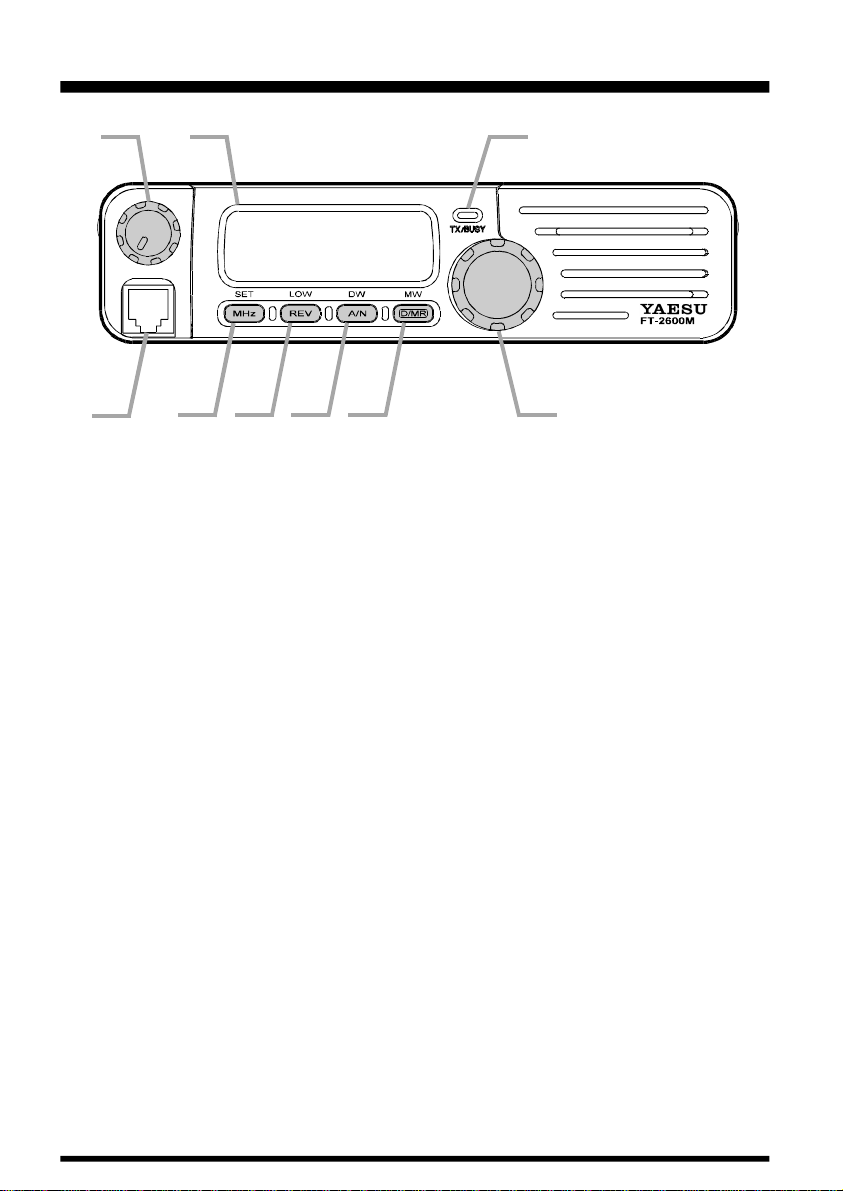
Front Panel Controls and Switches
(1) (8) (9)
(2) (3) (4) (5) (6) (7)
(1) Power / VOL Knob
Turn this control clockwise to turn the radio on and to increase the volume.
Counterclockwise rotation into the click-stop will turn the radio off.
(2) Microphone Jack
This 6-contact modular jack accepts transmit audio, tone call (burst) or Dial / Memory
selection, and Scanning control from the microphone.
Pin 1: SW 2 (Multi-function switching)
Pin 2: Cloning
Pin 3: +9V
Pin 4: GND
Pin 5: Microphone Input
Pin 6: SW 1 (Multi-function switching)
(3) MHz (SET) Key
This button allows tuning in 1-MHz steps (the MHz digits will blink on the display). If
receiving on a memory, pressing this button the first time activates the Memory Tune (MT)
mode, and pressing it again enables 1-MHz steps.
Press and hold this key for one second to activate the “Set” (MENU) Mode.
(4) REV (LOW) Key
During split-frequency operation, such as through a repeater, this button reverses the transmit and receive frequencies.
Press and hold this key for one second to change the transmitter power output level.
The available power levels are:
HIGH (60W) ⇒ LOW1 (25W) ⇒ LOW2 (10W) ⇒ LOW3 (5W) ⇒ HIGH (60W). . .
FT-2600M OPERATING MANUAL4
Front Panel Controls and Switches
(5) A/N (DW) Key
While receiving on a memory, pressing this button toggles the display between indication
of the frequency and the channel’s Alpha/Numeric label.
Press and hold this key for one second to activate the Dual Watch feature, described in the
Operation chapter (“PRI” will be displayed on the LCD, indicating “Priority Channel”
monitoring).
(6) D/MR (MW) Key
This button switches operation between the two main tuning modes: Dial and Memory
Recall.
Press and hold this key for one second to activate the Memory Storage mode.
(7) Main Dial Knob
This 20-position detented rotary switch is used for tuning, memory selection and most
function settings. Note that the microphone’s UP/DWN buttons duplicate the tuning functions of the Main Dial.
(8) BUSY/TX Indicator
This lamp glows green (during reception) when the channel is busy, and red during transmission.
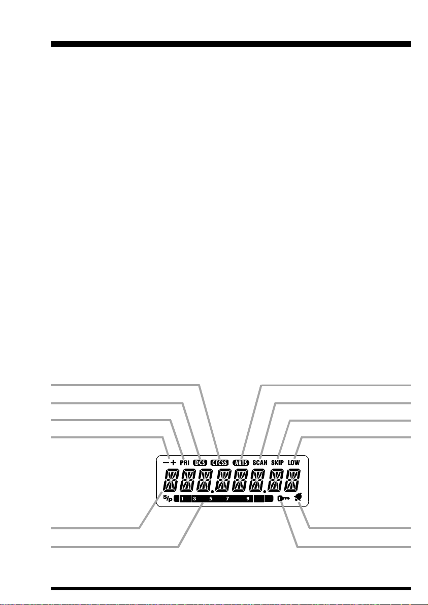
(9) Display
The main digits on the display may show operating frequency, memory name, and/or a
number of parameters during MENU configuration.
.
Continuous Tone Coded
Squelch System
Digital Code Squelch
Priority Channel
Repeater Shift Direction
Frequency /
Message Area
S - and Tx Power Meter
Automatic Range Transponder
System
SCAN Active
SKIP Active
LOW Power Selected
Bell Alarm Active
Key Lock Active
FT-2600M OPERATING MANUAL 5
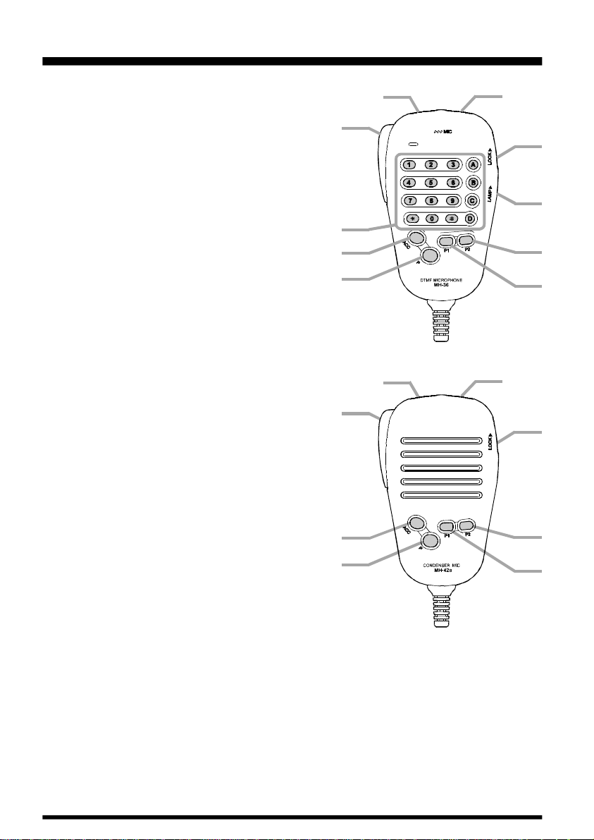
Microphone Switches (MH-36B6J)
(10) PTT Switch
Press this switch to transmit, and release it to receive.
(11) KEYPAD
The desired operating frequency may be entered directly from the keypad.
(12) DWN Button
Press this button momentarily to tune downward by
one synthesizer step. Hold this button in for one
second to start scanning.
(13) UP Button
Press this button momentarily to tune upward by
one synthesizer step. Hold this button in for one
second to start scanning.
(14) LOCK Switch
Slide this switch upward to lock the microphone’s
buttons.
(15) LAMP Switch
Slide this switch upward to activate the back-lighting for the microphone’s keys.
(10)
(11)
(16)
(17)
(10)
(12)
(12)
(13)
MH-36
(13)
(14)
(15)
(19)
(18)
B6J
(14)
(16) ACC Button (TSRCH)
This is one of three programmable-function keys
(ACC, P1, and P2) which may be used for control
of operating functions. The configuration of this key
is programmed via the MENU, and the default function is “Tone Search.”
(17) P Button (D/MR)
This key allows selection of the Dial, Home Channel,
or Memory Recall tuning methods.
(16)
(17)
MH-42
(19)
(18)
B6J
(18) P1 Button (SQL OFF)
The default function for this key is “Monitor” (Squelch Off).
(19) P2 Button (SSRCH)
The default function for this key is activation of the Smart Search™ feature.
Note: DTMF keys may not be availaable on some transceiver versions. Microphone ap-
pearance may differ slightly from that shown in the drawing.
FT-2600M OPERATING MANUAL6
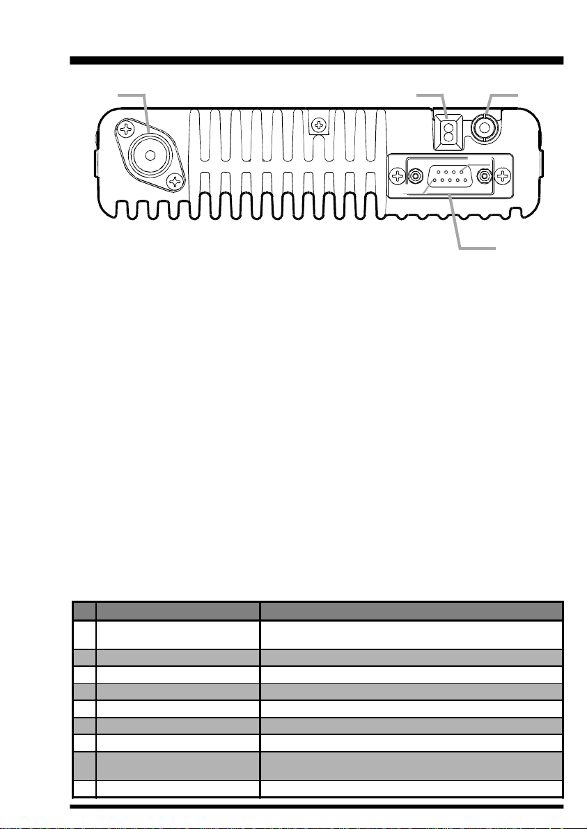
Rear Panel Connectors
(20) (22)(21)
Pin 9
Pin 1
(23)
(20) ANT Coaxial Socket
Connect a resonant 144-MHz antenna to this type-M (SO-239) socket using 50-W coaxial
cable and a type-M (PL-259) plug.
(21) 13.8V DC Cable Pigtail w/Fuse
This is the power supply connection for the transceiver. Use the supplied DC cable to
connect this pigtail to the car battery or other DC power supply capable of at least 10
Amperes (continuous duty). Make certain that the red lead connects to the positive side of
the supply. The fuse in the DC Cable is rated at 15-A, fast-blow.
(22) EXP SP Jack
This 2-contact 3.5-mm phone jack provides receiver audio output for an optional external
speaker. The audio impedance is 4 Ohms, and the level varies according to the setting of
the front panel’s VOL control. Inserting a plug into this jack disables audio from the
transceiver’s internal speaker.
(23) DSUB 9-Pin Data Connector
External Transmit Audio input, PTT (Push To Talk), Squelch, and Receive Audio output
signals may be obtained from this connector for use with accessories such as a data transmission/reception modem, etc.
Pin Label Notes
1 Squelch Signal Output
2 Packet Rx Data Output (9600 bps) Typ. output level 600 mV/10 kW
3 Packet Tx Data Input (9600 bps) Typ. input level 800 mV/600 W, Max. input 1.2 V
4 Packet Rx Data Output (1200 bps) Typ. output level 200 mV/600 W
5 Ground
6 Not Used
7 External PTT Signal Input GND: TX, Open: RX
8 DC Output
9 Packet Tx Data Input (1200 bps) Typ. input level 40 mV/600 W
Carrier In: Closed (Open Collector)
Maximum voltage 16 V, Max. sink current 10 mA
-
-
Switched and regulated DC 5.0 V output for supplying power to
an accessory. Maximum output current is 50 mA
FT-2600M OPERATING MANUAL 7

Installation
This chapter describes the installation procedure for integrating the FT-2600M into a typical amateur radio station. It is presumed that you possess technical knowledge and conceptual understanding consistent with your status as a licensed radio amateur. Please take
some extra time to make certain that the important safety and technical requirements detailed in this chapter are followed closely.
PRELIMINARY INSPECTION
Inspect the transceiver visually immediately upon opening the packing carton. Confirm
that all controls and switches work freely, and inspect the cabinet for any damage. Gently
shake the transceiver to verify that no internal components have been shaken loose due to
rough handling during shipping.
If any evidence of damage is discovered, document it thoroughly and contact the shipping
company (or your local dealer, if the unit was purchased over-the-counter) so as to get
instructions regarding the prompt resolution of the damage situation. Be certain to save the
shipping carton, especially if there are any punctures or other evidence of damage incurred
during shipping; if it is necessary to return the unit for service or replacement, use the
original packing materials but put the entire package inside another packing carton, so as
to preserve the evidence of shipping damage for insurance purposes.
INSTALLATION TIPS
To ensure long life of the components, be certain to provide adequate ventilation around
the cabinet of the FT-2600M.
Do not install the transceiver on top of another heat-generating device (such as a power
supply or amplifier), and do not place equipment, books, or papers on top of the FT-2600M.
Avoid heating vents and window locations that could expose the transceiver to excessive
direct sunlight, especially in hot climates. The FT-2600M should not be used in an environment where the ambient temperature exceeds +60º C (140º F).
SAFETY INFORMATION
The FT-2600M is an electrical apparatus, as well as a generator of RF (Radio Frequency)
energy, and you should exercise all safety precautions as are appropriate for this type of
device. These safety tips apply to any device installed in a well-designed amateur radio
station.
r Do not allow unsupervised children to play in the vicinity of your transceiver or an-
tenna installation.
r Be certain to wrap any wire or cable splices thoroughly with insulating electrical tape,
to prevent short circuits.
FT-2600M OPERATING MANUAL8

Installation
r Do not route cables or wires through door jambs or other locations where, through
wear and tear, they may become frayed and shorted to ground or to each other.
r Do not stand in front of a directional antenna while you are transmitting into that
antenna. Do not install a directional antenna in any location where humans or pets may
be walking in the main directional lobe of the antenna’s radiation pattern.
r In mobile installations, it is preferable to mount your antenna on top of the roof of the
vehicle, if feasible, so as to utilize the car body as a counterpoise for the antenna and
raise the radiation pattern as far away from passengers as possible.
r During vehicular operation when stopped (in a parking lot, for example), make it a
practice to switch to Low power if there are people walking nearby.
r Never wear dual-earmuff headphones while driving a vehicle.
RF FIELD EXPOSURE INFORMATION
This transceiver is capable of power output in excess of 50 Watts, so customers in the
United States may be required to demonstrate compliance with Federal Communications
Commission (FCC) regulations concerning maximum permissible exposure to radio frequency energy. Compliance is based on the actual power output used, feedline loss, antenna type and height, and other factors which can only be evaluated as a system.
Information regarding these regulations may be available from your Dealer, your local
radio club, from the FCC directly (press releases and other information can be found on the
FCC’s site on the World Wide Web at <http://www.fcc.gov>), or from the American Radio
Relay League, Inc. (225 Main St., Newington CT 06111 or <http://www.arrl.org>).
ANTENNA CONSIDERATIONS
The FT-2600M is designed for use with antennas presenting an impedance of near 50 W at
all operating frequencies. The antenna (or a 50 W dummy load) should be connected whenever the transceiver is turned on, to avoid damage that could otherwise result if transmission occurs accidentally without an antenna.
Ensure that your antenna is designed to handle 60 Watts of transmitter power. Some magnetic-mount mobile antennas, designed for use with hand-held transceivers, may not be
capable of this power level. Consult the antenna manufacturer’s specification sheet for
details.
Most all FM work is performed using vertical polarization. When installing a directional
antenna such as a Yagi or Quad, be certain to orient it so as to produce vertical polarization,
unless you are engaged in a special operating situation where horizontal polarization is
used.
FT-2600M OPERATING MANUAL 9
Installation
Note that this transceiver is designed with wide frequency coverage in the VHF spectrum.
For general listening, you may wish to have a broadband antenna such as a discone available, as a directional antenna such as a Yagi will have degraded performance outside the 2meter Amateur band.
Excellent reference texts and computer software are available for the design and optimization of VHF antennas. Your dealer should be able to assist you with all aspects of your
antenna installation requirements.
Use high-quality 50 W coaxial cable for the lead-in to your FT-2600M transceiver. All
efforts at providing an efficient antenna system will be wasted if poor quality, lossy coaxial
cable is used. Losses in coaxial lines increase as the frequency increases, so an 8-meterlong (25’) coaxial line with 0.75 dB of loss at 28 MHz may have a loss of 1.8 dB or more
at 146 MHz; choose your coaxial cable carefully based on the installation location (mobile
vs. base) and the overall length of the cable required (for very short runs of cable in a
mobile installation, the smaller, more flexible cable types may be acceptable).
For reference, the chart below shows approximate loss figures for typically-available coaxial cables frequently used in VHF installations.
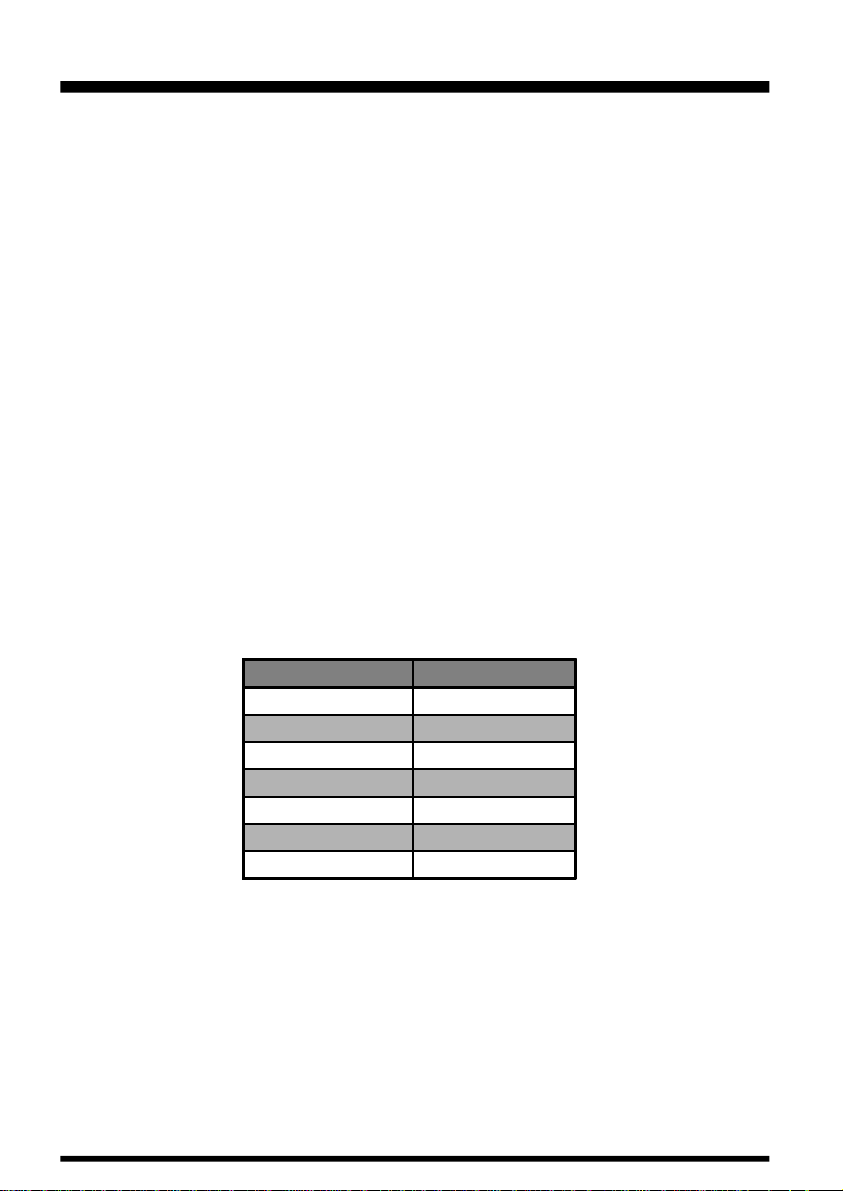
Loss in dB per 30 m (100 feet) for Selected 50 W Coaxial Cables
(Assumes 50 W Input/Output Terminations)
Cable Type Loss: 144 MHz
RG-58A 6.5
RG-58 Foam 4.7
RG-8A, RG-213 3.0
RG-8 Foam 2.0
â
Belden 9913 1.5
1/2" "Hardline" 1.0
7/8" "Hardline" 0.7
Loss figures are approximate; consult cable manufacturers’ catalogs for complete specifications.
In outdoor installations, be certain to weatherproof all connectors thoroughly, as water
entering a coaxial cable will cause losses to escalate rapidly, thus diminishing your communications effectiveness. The use of the shortest possible length of the highest quality
coaxial cable that fits within your budget will ensure the best performance from your FT2600M.
FT-2600M OPERATING MANUAL10

Installation
MOBILE INSTALLATION
The FT-2600M must only be installed in vehicles having a negative ground electrical
system. Mount the transceiver where the display, controls, and microphone are easily accessible, using the supplied MMB-73 mounting bracket. The transceiver may be installed
in any position, but should not be positioned near a heating vent nor anywhere where it
might interfere with driving (either visually or mechanically). Make sure to provide plenty
of space at the rear of the transceiver so that air can flow freely through the heatsink. Refer
to the diagrams showing proper installation procedures.
Transceiver Installation
r Choose a mounting location with sufficient clearance for the transceiver, plus space
for ventilation around the heat sink. Using the mounting bracket as a template for the
mounting holes, use a 4.8 mm (3/16”) bit to drill the mounting holes, and secure the
mounting bracket with the supplied screws, washers, and nuts (see diagram).
r Position the transceiver in the bracket so that the holes in the side are aligned with
those in the bracket, and bolt the transceiver into place using the supplied short screws
and flat washers.
FT-2600M OPERATING MANUAL 11
Installation
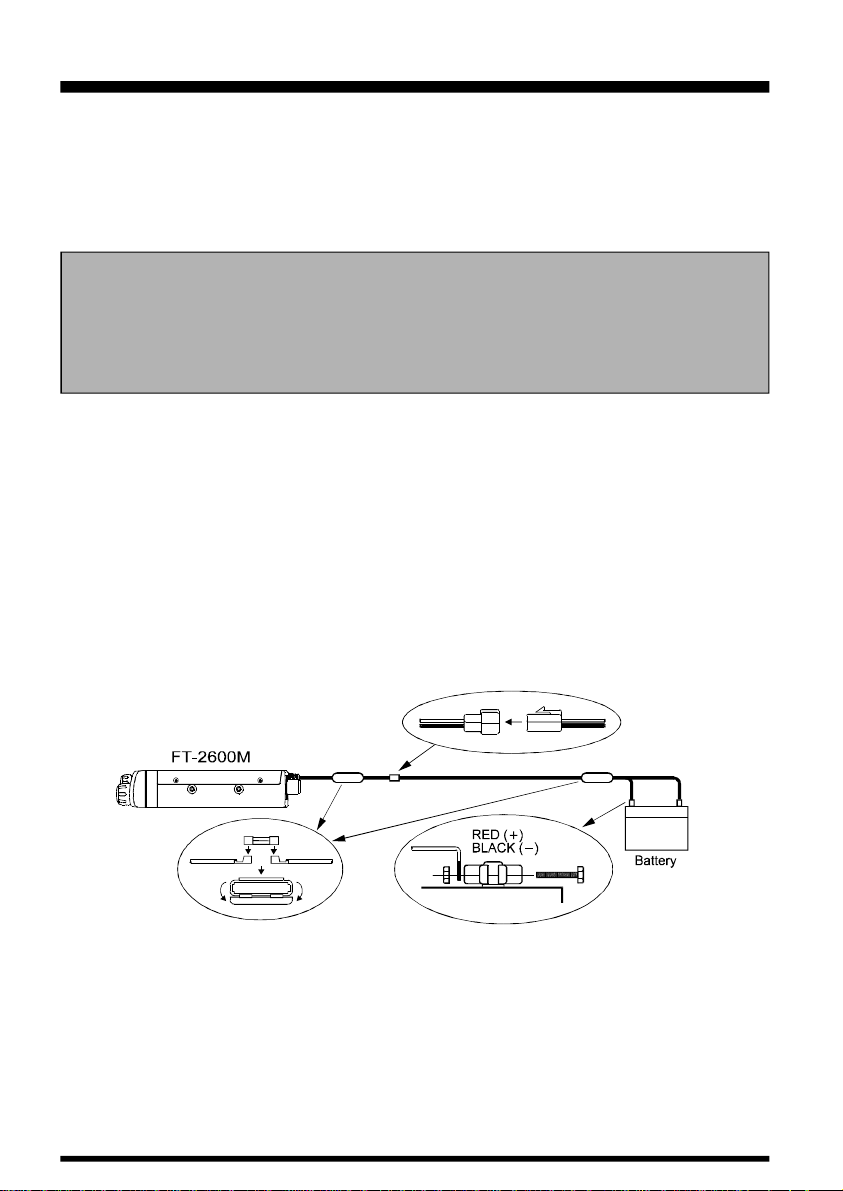
Mobile Power Connections
To minimize voltage drop and avoid blowing the vehicle’s fuses, connect the supplied DC
power cable directly to the battery terminals. Do not attempt to defeat or bypass the DC
cable’s fuse—it is there to protect you, your transceiver, and your vehicle’s electrical system.
Warning!
Never apply AC power to the power cable of the FT-2600M, nor DC voltage greater
than 15.2 Volts. When replacing the fuse, only use a 15-A fast-blow type. Failure to
observe these safety precautions will void the Limited Warranty on this product.
r Before connecting the transceiver, check the voltage at the battery terminals while
revving the engine. If the voltage exceeds 15 Volts, adjust the vehicle’s voltage regulator before proceeding with installation.
r Connect the RED power cable lead to the POSITIVE (+) battery terminal, and the BLACK
power cable lead to the NEGATIVE (-) terminal. If you need to extend the power cable,
use #12 AWG or larger insulated, stranded copper wire. Solder the splice connections
carefully, and wrap the connections thoroughly with insulating electrical tape.
r Before connecting the cable to the transceiver, verify the voltage and polarity of the
voltage at the transceiver end of the DC cable using a DC voltmeter. Now connect the
transceiver to the DC cable.
Mobile Speakers
The optional SP-7 External Speaker includes its own swivel-type mounting bracket, and is
available from your Yaesu dealer.
Other external speakers may be used with the FT-2600M, if they present the specified 4W impedance and are capable of handling the 3.5 Watts of audio output supplied by the
FT-2600M.
FT-2600M OPERATING MANUAL12
Installation
BASE STATION INSTALLATION
The FT-2600M is ideal for base station use as well as in mobile installations. The FT2600M is specifically designed to integrate into your station easily, using the information
to follow as a reference.
AC Power Supplies
Operation of the FT-2600M from an AC line requires a power source capable of providing
at least 10 Amps continuously at 13.8 Volts DC. The FP-1023A, FP-1025A, and FP-1030A
AC Power Supplies are available from your Yaesu dealer to satisfy these requirements.
Other well-regulated power supplies may be used, as well, if they meet the above voltage
and current specifications.
Use the DC power cable supplied with your transceiver for making power connections to the
power supply. Connect the RED power cable lead to the POSITIVE (+) power supply terminal, and connect the BLACK power cable lead to the NEGATIVE (-) power supply terminal.
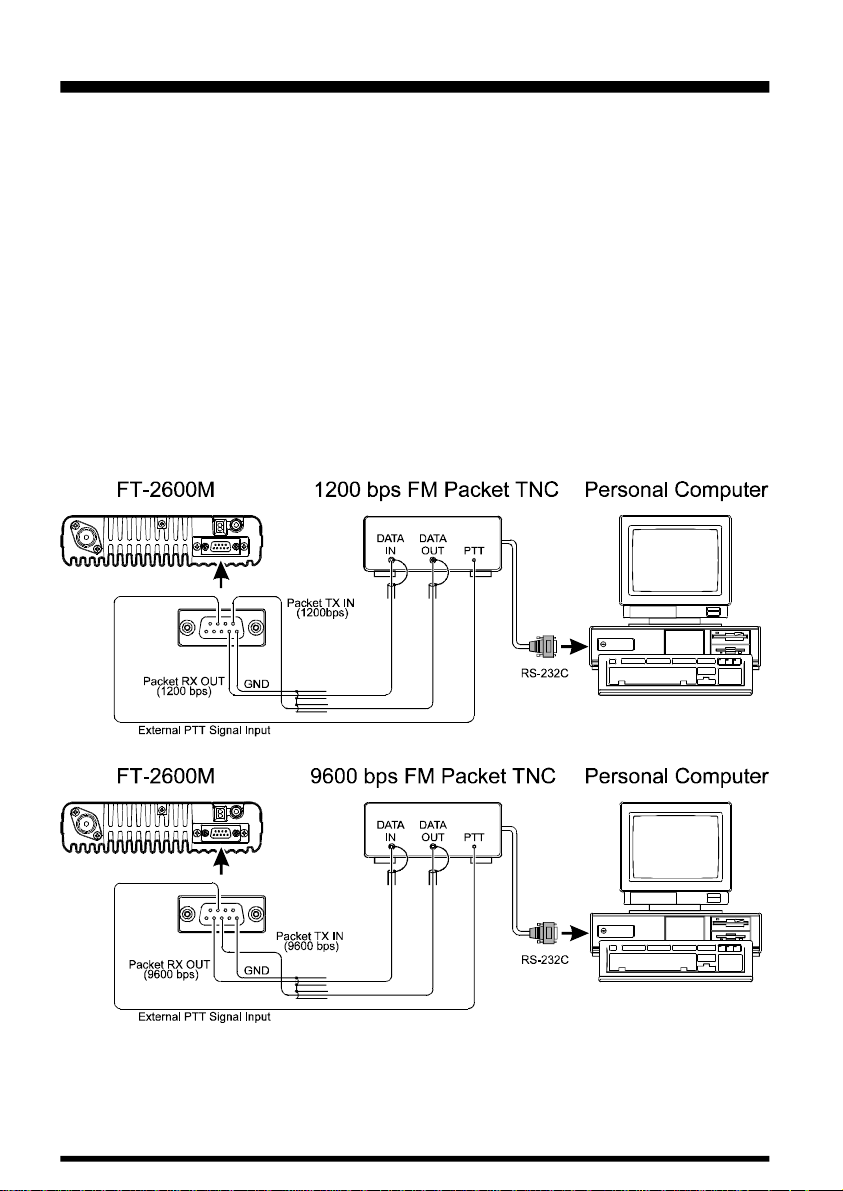
Packet Radio Terminal Node Controller (TNC)
The FT-2600M provides a convenient rear-panel DATA jack for easy connections to your
TNC. This connector is a standard Dsub 9-pin connector, widely available from electronics parts suppliers.
The FT-2600M’s DATA jack connections are optimized for the data transmission and reception speed in use. In accordance with industry standards, the signal levels, impedances, and
bandwidths are significantly different on 9600 bps as opposed to 1200 bps. If your TNC does
not provide multiple lines to accommodate such optimization, you may still be able to utilize
your TNC, if it is designed for multiple-radio use, by connecting the TNC “Radio 1” port to
the 1200 bps lines on the FT-2600M, and the “Radio 2” port to the 9600 bps lines.
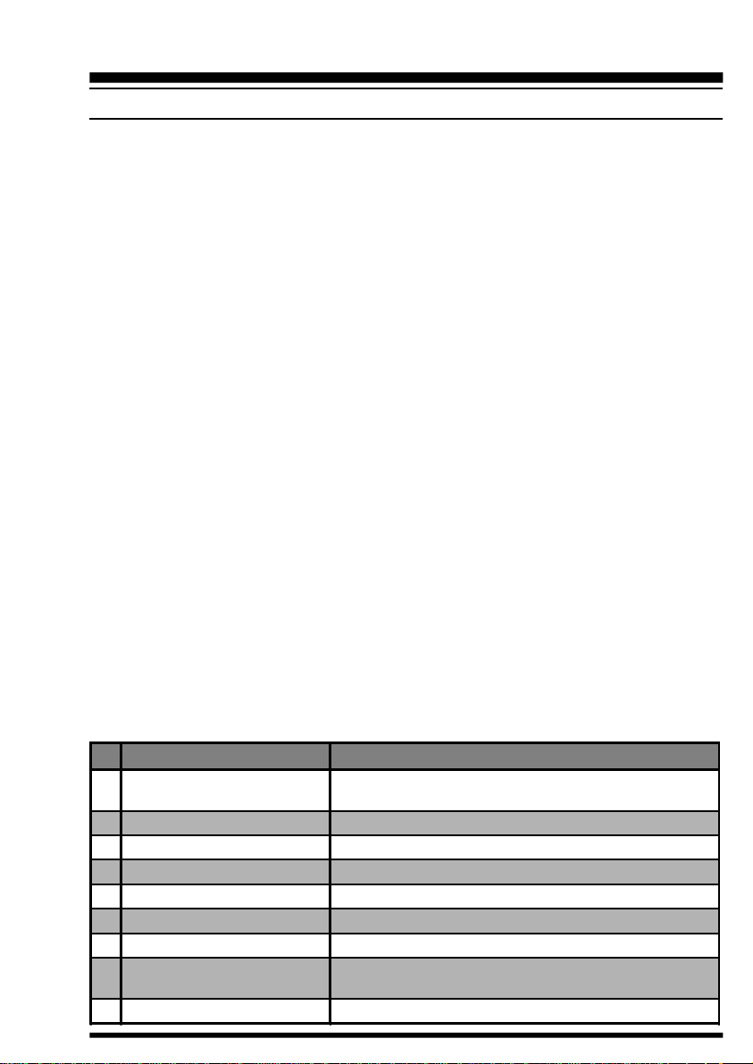
The pin connections of the DATA connector are shown below.
Pin Label Notes
1 Squelch Signal Output
2 Packet Rx Data Output (9600 bps) Typ. output level 600 mV/10 kW
3 Packet Tx Data Input (9600 bps) Typ. input level 800 mV/600 W, Max. input 1.2 V
4 Packet Rx Data Output (1200 bps) Typ. output level 200 mV/600 W
5 Ground
6 Not Used
7 External PTT Signal Input GND: TX, Open: RX
8 DC Output
9 Packet Tx Data Input (1200 bps) Typ. input level 40 mV/600 W
Carrier In: Closed (Open Collector)
Maximum voltage 16 V, Max. sink current 10 mA
-
-
Switched and regulated DC 5.0 V output for supplying power to
an accessory. Maximum output current is 50 mA
FT-2600M OPERATING MANUAL 13
Installation
Note that 9600 bps packet transmit-deviation adjustment is very critical to successful operation, and can only be accomplished using a calibrated deviation meter (such as that
found on an FM Service Monitor used in a communications service center). In most cases,
the Packet Data Input level (set via a potentiometer inside the TNC) must be adjusted to
provide a deviation of ±2.75 kHz (±0.25 kHz). Check with your packet node’s sysop if you
have any questions about the appropriate deviation level for your network.
The setting of the 1200 bps Packet Data Input level is much less critical, and satisfactory
adjustment to the optimum (±2.5 ~ ±3.5 kHz) deviation can usually be done “by ear” by
adjusting the TNC’s 1200 bps TX Audio Level potentiometer so that the outgoing packets
(as monitored on a separate VHF or UHF receiver) are approximately the same level as
(A) the DTMF tones or (B) the 1750 Hz Burst tone produced by the MH-36B6J or MH-42B6J
microphone.
Typical connections to a TNC are shown below.
Finally, note that MENU #18 (“PCKT”) allows you to enable or disable the microphone
during packet operation. Normally, the default setting (“Microphone Disabled during Packet
TX”) is appropriate; when the microprocessor detects PTT input from the Data connector,
the microphone will be disabled.
FT-2600M OPERATING MANUAL14

Operation
BASIC OPERATION/RECEPTION
POWER ON/OFF
Turn the Power / VOL Knob clockwise to turn on the radio.
The start-up channel will be the same one on which you were operating when the radio was
last turned off.
SUPPLY VOLT AGE DISPLAY
When you turn on the radio, the current DC supply voltage will be indicated on the display
for one second. After this interval, the display will resume its normal indication of the
operating frequency.
To view the supply voltage at any time during operation, use the following procedure:
(1) Press and hold the [MHz] key for one second to activate the “Set” (MENU) mode, then
rotate the Main Dial knob to select “09 DC IN.”
(2) Press the [MHz] key momentarily to display the current DC supply voltage on the
LCD.
(3) Press and hold in the [MHz] key for one second to exit to normal operation.
ADJUSTING THE VOLUME AND SQUELCH
Rotate the VOL control to adjust the receiver volume. Clockwise rotation increases the
audio output level.
The Squelch system is designed to keep the receiver quiet until a signal is received. The
Squelch should be adjusted to the point where the background noise is just silenced; any
“higher” setting will reduce the receiver’s sensitivity to weak signals.
To adjust the setting of the Squelch system:
(1) Rotate the Main Dial to select a clear frequency (where no signals are present).
(2) Press and hold in the [MHz] key for one second, then rotate the Main Dial knob to
select “28 SQL.”
(3) Press the [MHz] key momentarily, then rotate the Main Dial knob to select the squelch
threshold level (OFF, or 1 to 15). While you are making this adjustment, you will be
able to hear the background noise appear when the Squelch setting is too low. The best
sensitivity will be realized when the Squelch is set to one number past the point where
noise is muted.
(4) Press and hold in the [MHz] key for one second to save the new setting and exit to
normal operation.
A special “RF SQUELCH• feature is provided on this radio. This feature allows you to set the
squelch so that only signals exceeding a certain S-meter level will open the squelch.
FT-2600M OPERATING MANUAL 15

Operation
To set up the RF squelch circuit for operation, use the following procedure:
(1) Press and hold in the [MHz] key for one second, then rotate the Main Dial knob to
select “22 RFSQL.”
(2) Press the [MHz] key momentarily, then rotate the Main Dial knob to select the de-
sired signal strength level for the squelch threshold (OFF, S-3, S-5, S-7, S-9, or S-
FULL).
(3) Press and hold in the [MHz] key for one second to save the new setting and exit to
normal operation.
Note: The receiver’s squelch will open based on the highest level set by the two squelch
systems (Noise Squelch and RF Squelch). For example:
(1) If the Noise Squelch (Menu #28) is set so that signals at a level of S-3 will open the
squelch, but the RF Squelch (Menu #22) is set to “S-9,” the squelch will only open on
signals which are S-9 or stronger on the S-meter.
(2) If the RF Squelch is set to “S-3,” but the Noise Squelch is set to a high level which will
only pass signals which are Full Scale on the S-meter, the squelch will only open on
signals which are Full Scale on the S-meter. In this case, the Noise Squelch overrides
the action of the RF Squelch.
LOCK FEA TURE
If nothing happens when you press a button … the panel may be “locked” (this feature is
normally used to prevent accidental changes to the settings of controls and switches). To
unlock the front panel, use the following procedure:
(1) Press and hold in the [MHz] key for one second, then rotate the Main Dial knob to
select “17 LOCK.”
(2) Press the [MHz] key momentarily, then rotate the Main Dial knob to change the set-
ting to “OFF .”
(3) Press and hold the [MHz] key for one second to save the new setting and exit to
normal operation.
(4) To re-lock the front panel, select “ON” in step (2) above.
KEYPAD BEEPER
A key/button beeper provides useful audible feedback whenever a button is pressed. Each
key and button has a different beep pitch, and each function has a unique beep combination.
If you want to turn the beeper off (or back on again):
(1) Press and hold in the [MHz] key for one second, then rotate the Main Dial knob to
select “04 BEEP.”
(2) Press the [MHz] key, then rotate the Main Dial knob to select the display to “OFF.”
(3) Press and hold the [MHz] key for one second to save the new setting and exit to
normal operation.
FT-2600M OPERATING MANUAL16

Operation
DISPLAY BRIGHTNESS
The FT-2600M display illumination has been specially engineered to provide high visibility with minimal disruption of your “night vision” while you are driving. The brightness of
the display is manually adjustable, using the following procedure:
(1) Press and hold in the [MHz] key for one second, then rotate the Main Dial knob to
select “12 DIMR.”
(2) Press the [MHz] key, then rotate the Main Dial knob to select a comfortable bright-
ness level: D1, D2, D3, D4, or OFF (no illumination).
(3) Press and hold in the [MHz] key for one second to save the new setting and exit to
normal operation.
TUNING: THE “DIAL•E(VFO) MODE
This mode is used for selecting a frequency utilizing the Main Dial knob and microphone
[UP] and [DWN] buttons allow the Variable Frequency Oscillator (VFO) to tune in the
selected step size. When scanning in the VFO mode, the same steps are used as in manual
tuning.
Clockwise rotation of the Main Dial knob increases the operating frequency, while counterclockwise rotation tunes toward a lower frequency.
To move frequency rapidly (in 1 MHz steps), press the [MHz] key momentarily, then
rotate the Main Dial knob. The 1 MHz digit of the frequency display will blink while “1
MHz Tuning” is enabled. When you have selected the desired “1 MHz” frequency digit,
press the [MHz] key momentarily once more, then resume normal tuning using the Main
Dial knob.
CHANNEL STEP SELECTION
Tuning steps are factory preset to default increments which are appropriate for the country
to which this radio is exported.
To change to another step size, use the following procedure:
(1) Press and hold the [MHz] key for one second, then rotate the Main Dial knob to select
“29 STEP.”
(2) Press the [MHz] key, then rotate the Main Dial knob to select the desired step size:
5.0/10.0/12.5/15.0/20.0/25.0/50.0 (kHz).
(3) Press and hold in the [MHz] key for one second to save the new setting and exit to
normal operation.
FT-2600M OPERATING MANUAL 17
 Loading...