

Yaesu FT1DR, FT1DE, FT1D Quick Manual
Quick Manual
1
2
3
4
5
6
7
8
9
10
11
12
13
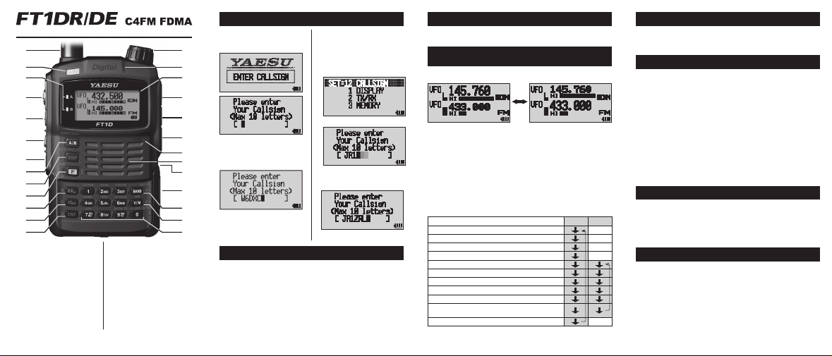
1 Antenna (SMA)
2 Strobe
3 A-band BUSY/TX lamp
B-band BUSY/TX lamp
4 PTT switch
5 MONI/SQL adjustment switch
6 VOL switch
7 Power switch
8 A/B-band toggle key
9 DISP toggle/SET mode key
10 Function/MW key
11 Communication mode toggle/
WIRES-X key
12 GM/SYNC key
13 ENT key
14 DIAL knob
15 GPS antenna
16 Display
17 MIC/SP Jack
18 EXT DC IN Jack
19 DATA Connector
20 Microphone
21 Speaker
22 Battery pack (back)
23 Micro SD memory card slot
24 BAND toggle/SCOPE key
25
VFO/memory mode toggle/DW key
26 Number keys (for setting
frequency and selecting function)
EH044M551
Entering/Changing Call Sign or Name
Enter a call sign or name when
operating the transceiver for the
first time or after a full reset.
14
15
16
17
18
19
Turn the D [DIAL] knob
and press E, or use the
20
keyboard. F removes one
21
character at a time.
22
23
24
Press the p [PTT] button, or
25
hold down E for one second,
to save the setting.
26
The entered call sign or name
can be changed at any time.
Hold down d for one second
or longer.
Select “12 CALLSIGN” by
turning the D [DIAL] knob.
Press E.
Change the call sign or name
by following the same steps as
the entry procedure.
Press the p [PTT] button.
If a Problem or Confusion Occurs During Operation
Pressing the p [PTT] button, while configuring settings in SET
mode, usually returns to the main screen of the current operating
mode.
* Full reset: Hold down x, G and E and press P (Power). Press
F in response to the screen directions. (This also clears all content
registered in the memory.)
* Reset only the SET mode settings: Hold down x and t and press
P (Power). Press F in response to the screen directions.
Adjusting the Volume
Hold down V, while turning the D knob to adjust the volume.
Press the V button briefly to turn the mute function on or off.
Selecting the Operating Band and Changing
Toggle between operating bands by pressing A.
The operating band frequency is displayed in large numbers.
Hold down A for one second or more to toggle between
mono band operation, in which only the operating band is
displayed, and the dual band operating display.
Presses B to switch between the operating receive
frequency bands displayed in the table below.
Press F and then B, to switch between the receive
bands in the opposite direction.
Transmission is possible in the 144 MHz and 430 MHz Amateur
bands.
0.5MHz - 1.8MHz (AM radio band)
76 (88) MHz - 108MHz (FM radio band)
1.8MHz - 30MHz (short wave band)
30MHz - 76 (88) MHz (50MHz band)
108MHz - 137MHz (aviation radio band)
137MHz - 174MHz (144MHz band)
174MHz - 222MHz
222MHz - 420MHz (information radio band (1))
420MHz - 470MHz (430MHz band)
470MHz - 774 (800) MHz
*B-band is capable of up to 580MHz only
803 (800) MHz - 999MHz (information radio band (2))
( ): EXP/European Version
the Frequency
A
Band
B
Band
Reception Frequency Bands
-
-
A-Band B-Band
──
──
──
──
──
Tuning the Frequency
In VFO mode, Change the frequency by turning the D [DIAL]
knob, or enter a frequency using the number keys.
(Press T to toggle between VFO and memory mode.)
Selecting a Communication Mode
Usually, select the auto communication mode. This automatically
changes the communication mode to that of the received signal.
* Digital communication is only possible on A-band.
Press X to toggle between communication modes.
“Analog (f)” → “Auto (_: Auto changing)” → “Digital
(o)” → “Wide digital (W)”
o: A simultaneous voice/data communication mode, in
which information (such as the call sign and position) is
communicated at the same time as the voice, in standard
C4FM modulation mode.
W: A full rate, high definition mode with emphasis on sound
quality for voice communication.
k: A high-speed data communication mode, to which the
radio automatically adjust when an image or GM operation
range signal is sent or received.
Changing Transmit Power Output
Press F, then 1, and then turn the D [DIAL] knob.
“HIGH” (5W) → “LOW1” (0.1W) → “LOW2” (1W) → “LOW3” (2.5W) →
(when connected to the lithium ion battery pack or an external power
source.)
Press p [PTT] to return to the frequency display.
Locking the Keys and Switch
Press P (power switch) briefly to lock the Keys and Switches.
Unlock by pressing P (power switch) again.
This transceiver can be used for digital communication with
other YAESU C4FM digital amateur transceivers; and also to
communicate with YAESU analog amateur transceivers.
When using Auto mode with A-band (n/w/m), the
transceiver will automatically recognize and communicate with
C4FM digital signals or analog signals used by the other station.
Do not transmit using fixed digital mode (o/W) if there is
any possibility that it may cause interference to other stations that
may be using analog signals.
* Select a mode according to the situation.
Communicating
Transmitting
Hold down p [PTT] and speak into the microphone, holding it
around 5 cm (2 inches) away.
The BUSY/TX lamp of the transmitter operating band (
is lit in red and the transmission output is shown on the PO meter
in the display.
■
A or ■B)
Receiving
Release p [PTT] to return to the receive mode.
When a C4FM digital signal is received in A-band, the
transmitting station’s call sign or name is displayed.
* The time duration of the displayed call sign in “DIGITAL”/“DIGI POPUP”
may be changed by holding down d for one second or longer, and
then turning the D [DIAL] knob to select “2 TX/RX” and pressing
E.
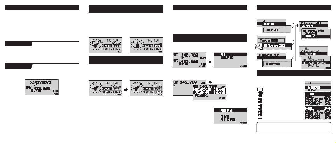
Automatically Displaying the Other
Press d to display the compass screen.
Select “Y” using the D [DIAL] knob to display the direction
and distance to the location from which the other station’s signal
is transmitted.
(C4FM digital signal or APRS beacon)
Turn the D [DIAL] knob and select “i” to display the
direction in which you are moving.
Registering Position Information and Using
“Y Displayed Indicated Position” and “i Displayed Own
Current Position” can be stored in S register.
Press E while displaying Y or i. The s, L or
l register is highlighted and flashes.
Station’s Position
BACKTRACK
D
Turn the D [DIAL] knob to highlight the mark (position) you
want to register and press E. The position information for the
selected mark -Y or i- is overwritten.
After registering the positions, turn the D [DIAL] knob and
select “S” to display the direction and distance from
your position to the registered position using the BACKTRACK
function.
Using GM (Group Monitor)
Group members are divided into members within communication
range, and members out of range. The direction and distance of
in-range members from your position can be displayed, allowing
you to ascertain their relative positions in real time.
Messages and images can also be exchanged with members.
(A Micro SD memory card is required to manage this data. Be sure to
install a memory card according to the instructions “Using a Micro SD
Memory Card” in the operating manual.)
Displaying In-Range and Out-of-Range Parties
in “ALL” Operation Without Group Settings
Tune the frequency in A-band, and then press G in auto
mode (_) or digital mode (o/W), to display the Select
Operation Group/Create New screen.
Turn the D [DIAL] knob, select a and press E.
This displays up to 24 in-range parties using GM operation on
that frequency.
In range
Still displayed
even when out of
Use the D [DIAL] knob to move the > cursor to a displayed
party and press E. The selected entry flashes. (Multiple
parties can be selected.) Hold
down E for one second or
longer to select “Create Group for
Selected Party”, “Add Selected
Party to an Existing Group”,
“Delete Selected Party” or “Delete
All Parties”.
* Press G while operating GM to exit GM operation and return to the
VFO/Memory operation screen.
range.
Select g in the Select Operation Group/Create New
screen to create up to 16 groups (up to 24 members each)
separate from “ALL” operation.
Enter a group name.
Enter a member name.
Creating a Group
Add a member.
Press
E
Hold down E
for one
second or
Hold down E for one second or longer
longer.
to complete creation of the group.
Other groups can be added in the same way.
Press
E
Hold down
E for one
second or
longer.
Checking Messages and Images
Press F and 7 to display the LOG, where you can check new
entries in your message list and image
list, create and send new messages, and
reply to or forward messages.
Create and send a new message
Message or image sent to the
displayed party
Message or image for which a reception
confirmation signal was not received
from the addressee
Read message or confirmed image
received from the displayed party
Unread message or unconfirmed image
received from the displayed party
Photograph taken with the optional
camera microphone
See the GM Function Online Manual for details on other functions such as:
• Creating a message • Editing and deleting groups or members
• The “SYNC” function, which syncs with other parties or operation group
members by radio • Transfer of group information via the Micro SD card
 Loading...