

Page 1

CopyCentre C118,
WorkCentre M118,
Service Documentation
701P23530
December 2004
CAUTION
Certain components in the CopyCentre C118,
WorkCentre M118, are susceptible to damage from
electrostatic discharge. Observe all ESD
procedures to avoid component damage.
Page 2

©
NOTICE
While Xerox has tried to make the documentation accurate, Xerox will have
no liability arising out of any inaccuracies or omissions.
NOTICE
All service docu mentation i s suppli ed to Xer ox exter nal cus tomer s for i nformational purposes only. Xerox service documentation is intended for use by
certified, product -trained s ervice pe rsonnel only. Xerox does not wa rrant or
represent that it will notify or provide to such customer any future change to
this documentation. Customer performed service of equipment, or modules,
components, or parts of such equipment may affect whether Xerox is
responsible to fix machine defects under the warranty offered by Xerox with
respect to such equipment . You shoul d consult the applicabl e warranty for
its terms regarding customer or third-party provided service.
WARNING
This equipment generates, uses and can radiate radio frequency
energy, and if not installed and used in accorda nce with the instructions documentation, may cause interference to radio communications. It has been tested and found to comply with the limits for a
Class A computing device pursuant to subpart J of part 15 of FCC
rules, which are designed to provide reasonable protection against
such interference w hen operat ed in a c ommercial envir onment. O peration of this equipment in a residen tial area is lik ely to cau se interference in which case the user, at his own expense, will be required to
correct the interference.
Published by The Document Company Xerox GKLS European Operations Bessemer Road
Welwyn Garden City Hertfordshire AL7 1HE ENGLAND
2004 by Fuji Xerox Co.,Ltd. All rights reserved.
The Document Company® and Xerox® are trade marks of the Xerox Corporation.
Xerox and all identifying numbers used in connection with the Xerox products mentioned in this
publication are trademarks of the Xerox Corporation.
Page 3

About this Manual .......................................................................................... .... .... .... ..... iii
Organization . ...................................................................................................................iii
How to Use this Document ation...................................................................................... iv
Symbology and Nomenclature........................................................................................ v
Translated Warnings..................................................................... .................................. viii
Introduction
Initial Issue
CCC118, WCM118
12/2004
i
Introduction
Page 4

About this Manual
This Service Manual is part of the multinational documentation system for
Copy Centre C118,Wor k Centre M118 copier/printers. The Service Documentation is used in
order to diagnose machine malfunctions, adjust components and has information which is
used to maintain the product in superior operating condition. It is the controlling publication for
a service call. Information on its use is found in the Introduction of the Serv ice Documentation.
This manual contains information that applies to NASG (XC) and ESG (XE) copiers.
Service Manual Revision
The Service Manual will be updated as the machine changes or as problem ar eas are identified.
Organization
This Service Manual is divided into eight sections. The t itles of the sections and a desc ription
of the information contained in each section are contained in the following paragraphs:
Section 1: Service Call Procedures
This section contains procedures that determine what actions are to be taken during a service
call on the machine and in what sequence they are to be completed. This is the entry level for
all service calls.
Section 2: Status Indicator RAPs
This section contains the diagnostic aids for troubleshooting the Fault Code and non-Fault
Code related faults (with the exception of image quality problems).
Section 3: Image Quality
This section contains the diagnostic aids for troubleshooting any image quality problems, as
well as image quality specifications and image defect samples.
Section 4: Repairs/Adjustments
This section contains all the Adjustments and Repair procedures.
Repairs
Repairs include procedures for removal and replacement of parts which have the following
special conditions:
When there is a personnel or machine safety issue.
When removal or replacement cannot be determined from the exploded view of the
Parts List.
When there is a cleaning or a lubricating activity associated with the procedure.
When the part requires an adjustment after replacement.
When a special tool is required for removal or replacement.
Use the repair procedures for the correct order of removal and replacement, for warnings, cautions, and notes.
Initial Issue
CCC118, WCM118
Adjustments
Adjustments include procedures for adjusting the parts that must be within specification for the
correct operation of the system.
Use the adjustment procedures for the correc t sequence of operation for s pecifications, wa rnings, cautions and notes.
Section 5: Parts Lists
This section contains the Copier/Printer Parts List.
Section 6: General Procedures Information
This section contains General Procedures, Diagnostic Programs, and Copier/Printer Information.
12/2004
iii
Introduction
Page 5

Section 7: Wiring Data
This section contains drawings, lists of plug/jack locations, and diagrams of the power distribution wire networks in the machine. This section also contains the Block Schematic Diagrams.
How to Use this Documentation
The Service Call Procedures in Section 1 describe the sequence of activities used during the
service call. The call must be entered using these procedures.
Section 8: Accessories
This section contains installation information for option and accessory.
Use of the Circuit Diagrams
All wirenets are shown on the Circuit Diagrams (CDs). Power distribution wirenets are shown
in Section 7 (Wiring Data) of the Service Ma nual. The power distribution wirenets on the C Ds
will end at the terminal board for the power being distributed. Find the wirenet for that power
and locate the terminal board on the wirenet. Use the wirenet to troubleshoot any power distribution wiring not shown on the CD.
Use of the Block Schematic Diagrams
Block Schematic Diagrams (BSDs) are included in Section 7 (Wiring Data) of the Service Manual. The BSDs show the functional relationship of the electrical circuitry to any mechanical, or
non-mechanical, inputs or outputs throughout the machine. Inputs and outputs such as motor
drive, mechanical linkages, operator actions, and air flow are shown. The BSDs will provide an
overall view of how the entire subsystem works.
It should be noted that the BSDs no longer contain an Input Power Block referring to Chain 1. It
will be necessary to refer to the Wirenets in order to trace a wire back to its source.
Introduction
12/2004
iv
Initial Issue
CCC118, WCM1 18
Page 6
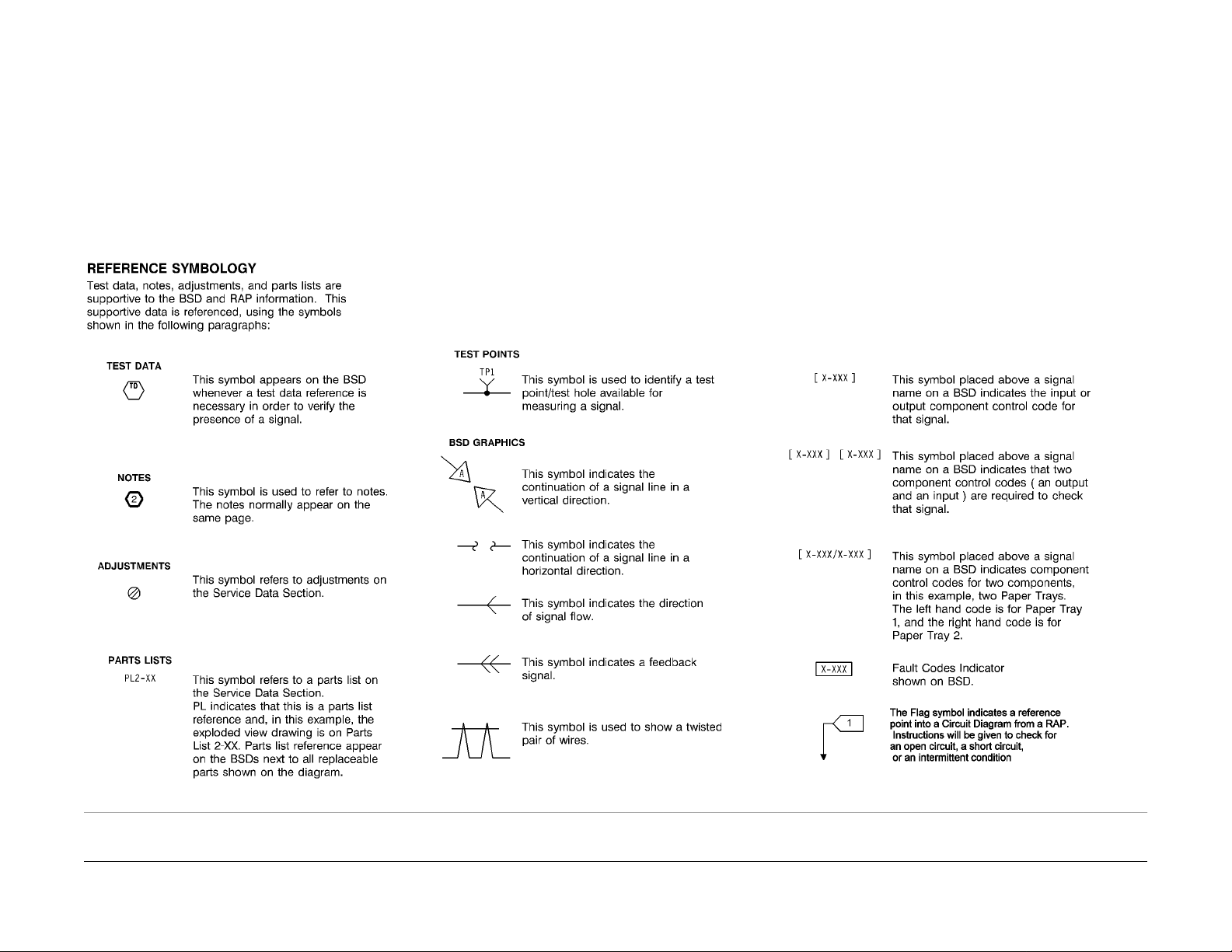
Symbology and Nomenclature
The following reference symbols are used throughout the documentation.
Warnings, Cautions, and Notes
Warnings, Cautions, and Notes will be found throughout the Service Documentation. The
words WARNING or CAUTION may be listed on an illustration when the specific component
associated with the potential hazard is pointed out; however, the message of the WARNING or
CAUTION is always located in the text. Their definitions are as follows:
WARNING
A Warning is used whenever an operating or maintenance proce dure, a p ractice, co ndition, or statement, if not strictly observed, could result in personal in j ury.
CAUTION
A Caution is used whenever an operating or maintenance procedure, a practic e, condition, or
statement, if not strictly observed, could result in damage to the equipment.
NOTE: A Note is used whenever it is necessary to highlight an operating or maintenance procedure, practice, condition, or statement.
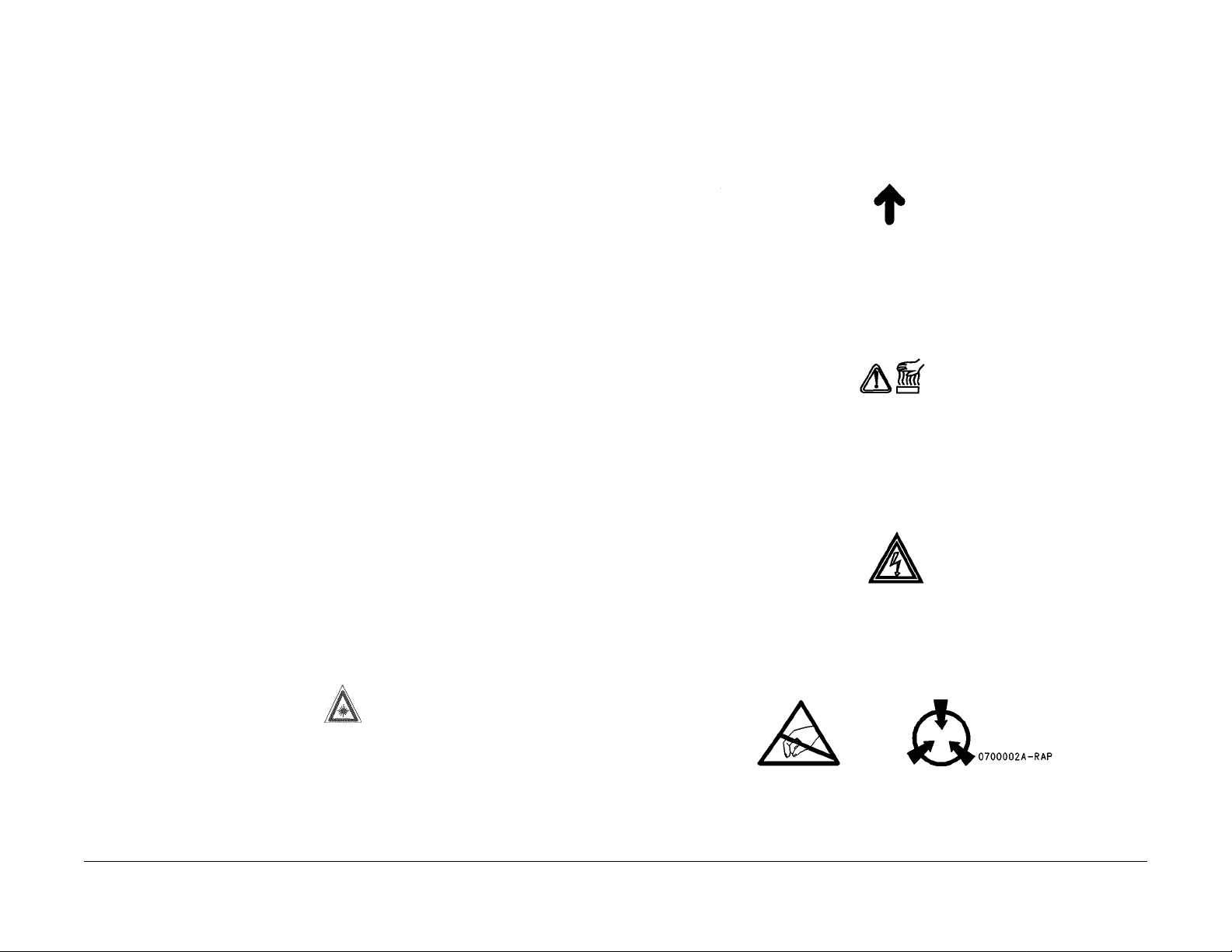
Machine Safety Icons
The following safety icons are displayed on the machine:
WARNING
This machine contains an invisible laser. There is no visual indication that the laser
beam is present. During servicing, the machine is a Class 3B product because of the
invisible laser. the laser beam could cause eye damage if lo oked at directly. Service procedures must be followed exactly as written without change. The service representative
must observe the established local laser safety precautions when servicing the
machine. Do not place tools with a reflective surface in the area of the ROS opening. Do
not look in the area of the ROS window if the power is On and the laser is energized.
The following symbol and statement appear on a label in the machine. The symbol by
itself, or the symbol and the statement may also appear in the service documentation
and in the training program. When this symbol appears, the service representative is
warned that conditions exist that could result in exposure to the laser beam.
WARNING
Do not try to bypass any laser interlocks for any reason. Permanent eye damage could
result if the laser is accidentally directed into your eye.
CAUTION
The use of controls or adjustments other than those specified in the Laser Safety Training Program may result in an exposure to dangerous laser radiation.
For additional information, review the Laser Safety Training program.
An arrow points to the location to install, to gain access to, or to release an object.
Figure 2 Customer Access Label
This symbol indicates that a surface can be hot. Use caution when reaching in the machine to
avoid touching the hot surfaces.
Figure 3 Heated Surface Label
Danger label indicates where electrical currents exist when the machine is closed and operating. Use caution when reaching in the machine.
Figure 4 Shock Hazard Label
These symbols indicate components that may be damaged by Electrostatic Discharge (ESD).
Figure 1 Laser Hazard Symbol
Laser Hazard Statement
DANGER INVISIBLE LASER RADIATION WHEN OPEN. AVOID DIRECT EXPOSURE TO
BEAM.
Initial Issue
CCC118, WCM118
12/2004
v
Figure 5 ESD warning Label
Introduction
Page 7
Electrostatic Discharge (ESD) Field Service Kit
The purpose of the ESD Protection Program is to preserve the inherent reliability and quality of
electronic components that are handled by the Field Service Personnel. Th is prog ram is being
implemented now as a direct result of advances in microcircuit ry technology, as well as a new
acknowledgment of the magnitude of the ESD problem in the electronics industry today.
This program will reduce Field Service costs that are charged to PWB failures. Ninety percent
of all PWB failures that are ESD related do not occur immediately. Using the ESD Field Service
Kit will eliminate these delayed failures and intermittent problems caused by ESD. This w ill
improve product reliability and reduce callbacks.
The ESD Field Service Kit should be used whenever Printed Wiring Boards or ES D sensitive
components are being handled. This includes activities like replacing or reseating of circ uit
boards or connectors. The kit should also be used in order to prevent additional damage when
circuit boards are returned for repair.
The instructions for using the ESD Field Service Kit can be found in ESD Field Service Kit
Usage in the General Procedures section of the Service Documentation.
Illustration Symbols
Figure 6 shows symbols and conventions that are commonly used in illustrations.
Introduction
Figure 6 Illustration Symbols
12/2004
vi
Initial Issue
CCC118, WCM1 18
Page 8
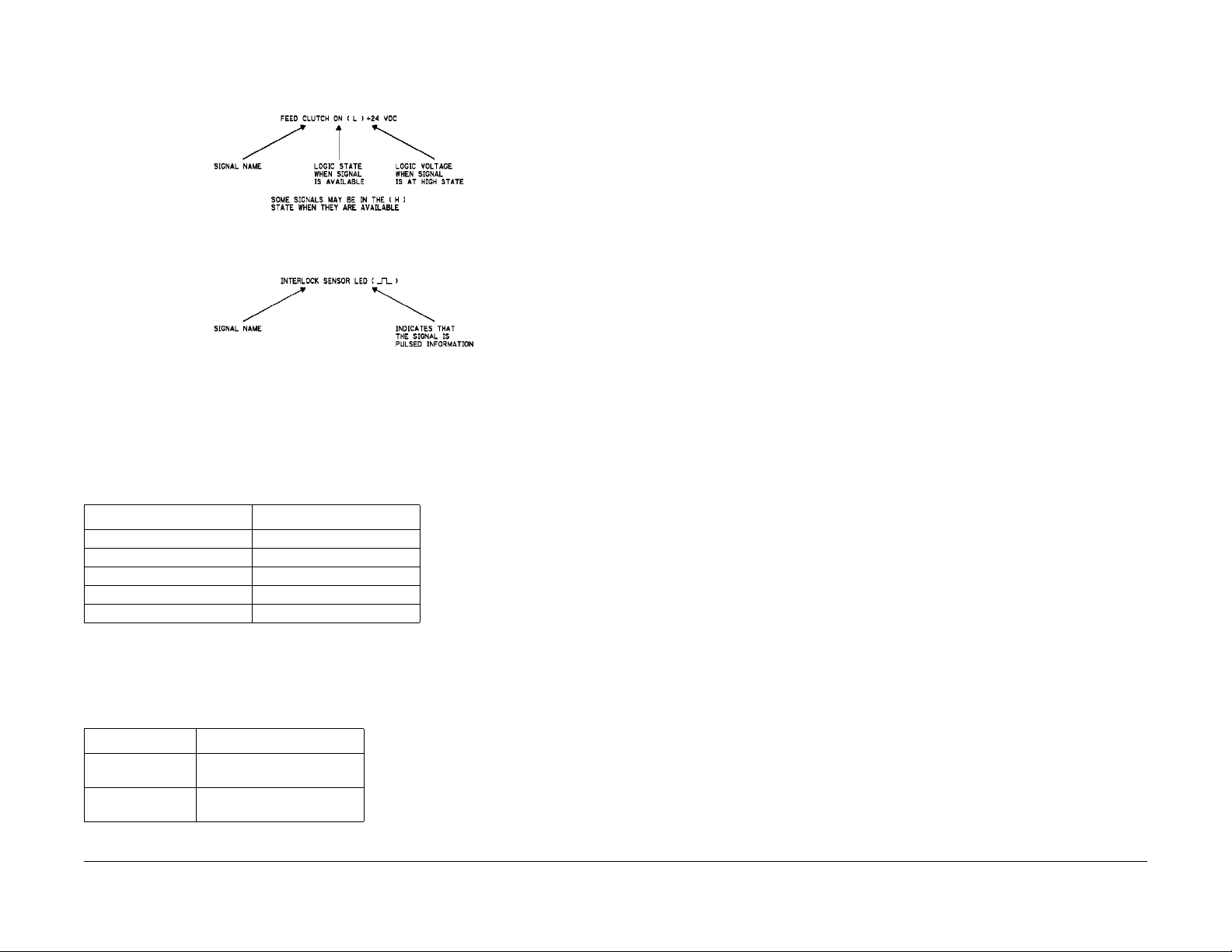
Signal Nomenclature
Refer to Figure 7 for an example of Signal Nomenclature used in Circuit Diagrams and BSDs.
Figure 7 Signal Nomenclature
Voltage Measurement and Specifications
Measurements of DC voltage must be made with reference to the specified DC Common,
unless some other point is referenced in a diagnostic procedure. All measurements of AC voltage should be made with respect to the adjacent return or ACN wire.
Table 1 Voltage Measurement and Specifications
VOLTAGE SPECIFICATION
INPUT POWER 220 V 198 VAC TO 242 VAC
INPUT POWER 100 V 90 VAC TO 135 VAC
INPUT POWER 120 V 90 VAC TO 135 VAC
+5 VDC +4.75 VDC TO +5.25 VDC
+24 VDC +23.37 VDC TO +27.06 VDC
DC Voltage Measurements in RAPs
The RAPs have been designed so that when it is required to use the DMM to measure a DC
voltage, the first test point listed is the location for the red (+) meter lead and the second test
point is the location for the black meter lead. For example, the following statement may be
found in a RAP:
There is +5 VDC from TP7 to TP68.
In this example, the red meter lead would be placed on TP7 and the black meter lead on TP68.
Another example of a statement found in a RAP might be:
There is -15 VDC from TP21 to TP33.
In this example, the red meter lead would be placed on TP21 and the black meter lead would
be placed on TP33.
If a second test point is not given, it is assumed that the black meter lead may be attached to
the copier frame.
Logic Voltage Levels
Measurements of logic levels must be made with reference to the specified DC Common,
unless some other point is referenced in a diagnostic procedure.
Table 2 Logic Levels
VOLTAGE H/L SPECIFICATIONS
+5 VDC H= +3.00 TO +5.25 VDC
L= 0.0 TO 0.8 VDC
+24 VDC H= +23.37 TO +27.06 VDC
L= 0.0 TO 0.8 VDC
Initial Issue
CCC118, WCM118
12/2004
vii
Introduction
Page 9

T rans lat ed Warnings
Introduction
12/2004
viii
Initial Issue
CCC118, WCM1 18
Page 10

Introduction
Symbology and Nomenclatur e
WARNING
A Warning is used whenever an operating or maintenance proce dure, a p ractice, co ndition, or statement, if not strictly observed, could result in personal in j ury.
DANGER: Une note DANGER est utilisée à chaque fois qu'une procédure de maintenance ou qu'une manipulation présente un risque de blessure si elle n'a pas été strictement observée.
WARNING
This machine contains an invisible laser. There is no visual indication that the laser
beam is present. During servicing, the machine is a Class 3B product because of the
invisible laser. the laser beam could cause eye damage if lo oked at directly. Service procedures must be followed exactly as written without change. The service representative
must observe the established local laser safety precautions when servicing the
machine. Do not place tools with a reflective surface in the area of the ROS opening. Do
not look in the area of the ROS window if the power is On and the laser is energized.
DANGER: L'équipement contient un faisceau laser invisible et aucune indication visible
signale la présence du faisceau laser. De ce fait le produit est classé 3B pour tout ce qui
concerne la maintenance. L'exposition directe des yeux au faisceau laser peut entraîner
des lésions visuelles. Les procédures de maintenance doivent être réalisées sans
aucun changement comme indiqué dans la documentation. Le représentant Xerox lors
d'interventions sur l'équipement doit respecter les consignes de sécurité locales concernant les faisceaux laser. Ne pas placer d'objet réfléchissant dans la zone du ROS
quand il est ouvert. Ne pas regarder dans la zone du ROS lorsque la machine est sous
tension et que le laser est en fonctionnement.
The following symbol and statement appear on a label in the machine. The symbol by
itself, or the symbol and the statement may also appear in the service documentation
and in the training program. When this symbol appears, the service representative is
warned that conditions exist that could result in exposure to the laser beam.
DANGER: Les symboles et instructions suivants sont indiqués sur des étiquettes dans
la machine et sont identifiés dans la documentation technique et dans le manuel de formation. Quand ces symboles s'affichent le représentant Xerox est prévenu d es risques
encourus concernant une exposition au rayon laser.
WARNING
Do not try to bypass any laser interlocks for any reason. Permanent eye damage could
result if the laser is accidentally directed into your eye.
DANGER: Ne pas essayer de shunter les contacts laser pour quelques raisons que ce
soit. Si le faisceau laser est dirigé accidentellement vers les yeux il peut en résulter des
lésions oculaires permanentes.
4 Repairs and Adjustments
Drives
REP 1.1.1 Main Drive Assembly
WARNING
To avoid personal injury or shock, do not perform repair or adjustment with electrical
power applied to the machine.
DANGER: Afin d'eviter des blessures ou des chocs electriques, ne pas effectuer maintenance ou reglage avec le cordon d'alimentation branche.
Paper Transportation
REP 2.2.1 Retard Pad
WARNING
To avoid personal injury or shock, do not perform repair or adjustment with electrical
power applied to the machine.
DANGER: Afin d'eviter des blessures ou des chocs electriques, ne pas effectuer maintenance ou reglage avec le cordon d'alimentation branche.
REP 2.4.1 Registration Unit
WARNING
To avoid personal injury or shock, do not perform repair or adjustment with electrical
power applied to the machine.
DANGER: Afin d'eviter des blessures ou des chocs electriques, ne pas effectuer maintenance ou reglage avec le cordon d'alimentation branche.
REP 2.5.1 Left Chute Unit
WARNING
To avoid personal injury or shock, do not perform repair or adjustment with electrical
power applied to the machine.
DANGER: Afin d'eviter des blessures ou des chocs electriques, ne pas effectuer maintenance ou reglage avec le cordon d'alimentation branche.
REP 2.5.2 BTR
WARNING
To avoid personal injury or shock, do not perform repair or adjustment with electrical
power applied to the machine.
DANGER: Afin d'eviter des blessures ou des chocs electriques, ne pas effectuer maintenance ou reglage avec le cordon d'alimentation branche.
ROS
REP 3.1.1 ROS Unit
WARNING
To avoid personal injury or shock, do not perform repair or adjustment with electrical
power applied to the machine.
DANGER: Afin d'eviter des blessures ou des chocs electriques, ne pas effectuer maintenance ou reglage avec le cordon d'alimentation branche.
Xerographics/Development
REP 4.1.1 XERO/Developer Cartridge
WARNING
To avoid personal injury or shock, do not perform repair or adjustment with electrical
Initial Issue
CCC118, WCM118
12/2004
ix
Introduction
Page 11

power applied to the machine.
DANGER: Afin d'eviter des blessures ou des chocs electriques, ne pas effectuer mainte-
nance ou reglage avec le cordon d'alimentation branche.
REP 4.1.2 Toner Cartridge
WARNING
To avoid personal injury or shock, do not perform repair or adjustment with electrical
power applied to the machine.
DANGER: Afin d'eviter des blessures ou des chocs electriques, ne pas effectuer maintenance ou reglage avec le cordon d'alimentation branche.
REP 4.2.1 Dispense Motor
WARNING
To avoid personal injury or shock, do not perform repair or adjustment with electrical
power applied to the machine.
DANGER: Afin d'eviter des blessures ou des chocs electriques, ne pas effectuer maintenance ou reglage avec le cordon d'alimentation branche.
Fuser
REP 5.1.1 Fuser Assembly
WARNING
To avoid personal injury or shock, do not perform repair or adjustment with electrical
power applied to the machine.
DANGER: Afin d'eviter des blessures ou des chocs electriques, ne pas effectuer maintenance ou reglage avec le cordon d'alimentation branche.
Exit
REP 6.1.1 Exit + OCT Assembly
WARNING
To avoid personal injury or shock, do not perform repair or adjustment with electrical
power applied to the machine.
DANGER: Afin d'eviter des blessures ou des chocs electriques, ne pas effectuer maintenance ou reglage avec le cordon d'alimentation branche.
MPT
REP 7.1.1 MPT Unit
WARNING
To avoid personal injury or shock, do not perform repair or adjustment with electrical
power applied to the machine.
DANGER: Afin d'eviter des blessures ou des chocs electriques, ne pas effectuer maintenance ou reglage avec le cordon d'alimentation branche.
REP 7.2.1 MPT Retard Pad
WARNING
To avoid personal injury or shock, do not perform repair or adjustment with electrical
power applied to the machine.
DANGER: Afin d'eviter des blessures ou des chocs electriques, ne pas effectuer maintenance ou reglage avec le cordon d'alimentation branche.
Electrical Components
REP 9.1.1 MCU PWB
WARNING
To avoid personal injury or shock, do not perform repair or adjustment with electrical
power applied to the machine.
DANGER: Afin d'eviter des blessures ou des chocs electriques, ne pas effectuer maintenance ou reglage avec le cordon d'alimentation branche.
REP 9.2.1 ESS PWB
WARNING
To avoid personal injury or shock, do not perform repair or adjustment with electrical
power applied to the machine.
DANGER: Afin d'eviter des blessures ou des chocs electriques, ne pas effectuer maintenance ou reglage avec le cordon d'alimentation branche.
Covers
REP 10.1.1 Top Cover
WARNING
To avoid personal injury or shock, do not perform repair or adjustment with electrical
power applied to the machine.
DANGER: Afin d'eviter des blessures ou des chocs electriques, ne pas effectuer maintenance ou reglage avec le cordon d'alimentation branche.
REP 10.2.1 Rear Cover
WARNING
To avoid personal injury or shock, do not perform repair or adjustment with electrical
power applied to the machine.
DANGER: Afin d'eviter des blessures ou des chocs electriques, ne pas effectuer maintenance ou reglage avec le cordon d'alimentation branche.
IIT
REP 11.1.1 Control Panel
WARNING
To avoid personal injury or shock, do not perform repair or adjustment with electrical
power applied to the machine.
DANGER: Afin d'eviter des blessures ou des chocs electriques, ne pas effectuer maintenance ou reglage avec le cordon d'alimentation branche.
REP 11.2.1 IIT Carriage Assembly
Introduction
12/2004
x
Initial Issue
CCC118, WCM1 18
Page 12

WARNING
To avoid personal injury or shock, do not perform repair or adjustment with electrical
power applied to the machine.
DANGER: Afin d'eviter des blessures ou des chocs electriques, ne pas effectuer maintenance ou reglage avec le cordon d'alimentation branche.
REP 11.2.2 NBCR-Host/NBCR-Power Cable
WARNING
To avoid personal injury or shock, do not perform repair or adjustment with electrical
power applied to the machine.
DANGER: Afin d'eviter des blessures ou des chocs electriques, ne pas effectuer maintenance ou reglage avec le cordon d'alimentation branche.
REP 11.4.1 Exposure Lamp
WARNING
To avoid personal injury or shock, do not perform repair or adjustment with electrical
power applied to the machine.
DANGER: Afin d'eviter des blessures ou des chocs electriques, ne pas effectuer maintenance ou reglage avec le cordon d'alimentation branche.
REP 11.5.1 Front/Rear Carriage Cable
WARNING
To avoid personal injury or shock, do not perform repair or adjustment with electrical
power applied to the machine.
DANGER: Afin d'eviter des blessures ou des chocs electriques, ne pas effectuer maintenance ou reglage avec le cordon d'alimentation branche.
REP 11.5.2 NSC/NBCR PWB
WARNING
To avoid personal injury or shock, do not perform repair or adjustment with electrical
power applied to the machine.
DANGER: Afin d'eviter des blessures ou des chocs electriques, ne pas effectuer maintenance ou reglage avec le cordon d'alimentation branche.
REP 11.5.3 Image Inverter PWB
WARNING
To avoid personal injury or shock, do not perform repair or adjustment with electrical
power applied to the machine.
DANGER: Afin d'eviter des blessures ou des chocs electriques, ne pas effectuer maintenance ou reglage avec le cordon d'alimentation branche.
REP 11.6.1 MFC and EXT PWB Box
WARNING
To avoid personal injury or shock, do not perform repair or adjustment with electrical
power applied to the machine.
DANGER: Afin d'eviter des blessures ou des chocs electriques, ne pas effectuer mainte-
nance ou reglage avec le cordon d'alimentation branche.
REP 1 1.6.2 EXT PWB
WARNING
To avoid personal injury or shock, do not perform repair or adjustment with electrical
power applied to the machine.
DANGER: Afin d'eviter des blessures ou des chocs electriques, ne pas effectuer maintenance ou reglage avec le cordon d'alimentation branche.
Tray Module -2T
REP 12.1.1 Tray 3 Feeder
WARNING
To avoid personal injury or shock, do not perform repair or adjustment with electrical
power applied to the machine.
DANGER: Afin d'eviter des blessures ou des chocs electriques, ne pas effectuer maintenance ou reglage avec le cordon d'alimentation branche.
REP 12.1.2 Tray 4 Feeder
WARNING
To avoid personal injury or shock, do not perform repair or adjustment with electrical
power applied to the machine.
DANGER: Afin d'eviter des blessures ou des chocs electriques, ne pas effectuer maintenance ou reglage avec le cordon d'alimentation branche.
REP 12.3.1 Feed/Retard/Nudger Roll
WARNING
To avoid personal injury or shock, do not perform repair or adjustment with electrical
power applied to the machine.
DANGER: Afin d'eviter des blessures ou des chocs electriques, ne pas effectuer maintenance ou reglage avec le cordon d'alimentation branche.
REP 12.6.1 2TM PWB
WARNING
To avoid personal injury or shock, do not perform repair or adjustment with electrical
power applied to the machine.
DANGER: Afin d'eviter des blessures ou des chocs electriques, ne pas effectuer maintenance ou reglage avec le cordon d'alimentation branche.
REP 12.7.1 Left Lower Cover
WARNING
To avoid personal injury or shock, do not perform repair or adjustment with electrical
power applied to the machine.
DANGER: Afin d'eviter des blessures ou des chocs electriques, ne pas effectuer maintenance ou reglage avec le cordon d'alimentation branche.
Tray Module -ST
Initial Issue
CCC118, WCM118
12/2004
xi
Introduction
Page 13

REP 13.1.1 Tray 2 Feeder
WARNING
To avoid personal injury or shock, do not perform repair or adjustment with electrical
power applied to the machine.
DANGER: Afin d'eviter des blessures ou des chocs electriques, ne pas effectuer maintenance ou reglage avec le cordon d'alimentation branche.
REP 13.3.1 Feed/Retard/Nudger Roll
WARNING
To avoid personal injury or shock, do not perform repair or adjustment with electrical
power applied to the machine.
DANGER: Afin d'eviter des blessures ou des chocs electriques, ne pas effectuer maintenance ou reglage avec le cordon d'alimentation branche.
DADF/ADF
REP 15.1.1 DADF/ADF
WARNING
To avoid personal injury or shock, do not perform repair or adjustment with electrical
power applied to the machine.
DANGER: Afin d'eviter des blessures ou des chocs electriques, ne pas effectuer maintenance ou reglage avec le cordon d'alimentation branche.
REP 15.1.2 DADF/ADF Platen Cushion
WARNING
To avoid personal injury or shock, do not perform repair or adjustment with electrical
power applied to the machine.
DANGER: Afin d'eviter des blessures ou des chocs electriques, ne pas effectuer maintenance ou reglage avec le cordon d'alimentation branche.
REP 15.2.1 Document Tray Assembly
WARNING
To avoid personal injury or shock, do not perform repair or adjustment with electrical
power applied to the machine.
DANGER: Afin d'eviter des blessures ou des chocs electriques, ne pas effectuer maintenance ou reglage avec le cordon d'alimentation branche.
REP 15.2.2 DADF/ADF Feeder Assembly
WARNING
To avoid personal injury or shock, do not perform repair or adjustment with electrical
power applied to the machine.
DANGER: Afin d'eviter des blessures ou des chocs electriques, ne pas effectuer maintenance ou reglage avec le cordon d'alimentation branche.
REP 15.2.3 Front Cover
WARNING
To avoid personal injury or shock, do not perform repair or adjustment with electrical
power applied to the machine.
DANGER: Afin d'eviter des blessures ou des chocs electriques, ne pas effectuer maintenance ou reglage avec le cordon d'alimentation branche.
REP 15.2.4 Rear Cover
WARNING
To avoid personal injury or shock, do not perform repair or adjustment with electrical
power applied to the machine.
DANGER: Afin d'eviter des blessures ou des chocs electriques, ne pas effectuer maintenance ou reglage avec le cordon d'alimentation branche.
REP 15.3.1 DADF/ADF Control PWB
WARNING
To avoid personal injury or shock, do not perform repair or adjustment with electrical
power applied to the machine.
DANGER: Afin d'eviter des blessures ou des chocs electriques, ne pas effectuer maintenance ou reglage avec le cordon d'alimentation branche.
REP 15.3.2 Left Counter Balance
WARNING
To avoid personal injury or shock, do not perform repair or adjustment with electrical
power applied to the machine.
DANGER: Afin d'eviter des blessures ou des chocs electriques, ne pas effectuer maintenance ou reglage avec le cordon d'alimentation branche.
REP 15.3.3 Right Counter Balance
WARNING
To avoid personal injury or shock, do not perform repair or adjustment with electrical
power applied to the machine.
DANGER: Afin d'eviter des blessures ou des chocs electriques, ne pas effectuer maintenance ou reglage avec le cordon d'alimentation branche.
REP 15.4.1 Top Cover
WARNING
To avoid personal injury or shock, do not perform repair or adjustment with electrical
power applied to the machine.
DANGER: Afin d'eviter des blessures ou des chocs electriques, ne pas effectuer maintenance ou reglage avec le cordon d'alimentation branche.
REP 15.8.1 Retard Roll
WARNING
To avoid personal injury or shock, do not perform repair or adjustment with electrical
power applied to the machine.
DANGER: Afin d'eviter des blessures ou des chocs electriques, ne pas effectuer maintenance ou reglage avec le cordon d'alimentation branche.
Introduction
12/2004
xii
Initial Issue
CCC118, WCM1 18
Page 14

REP 15.9.1 Pickup Roll, Feed Roll
WARNING
To avoid personal injury or shock, do not perform repair or adjustment with electrical
power applied to the machine.
DANGER: Afin d'eviter des blessures ou des chocs electriques, ne pas effectuer maintenance ou reglage avec le cordon d'alimentation branche.
IIT
ADJ 11.1.1 Carriage Assembly Position Adjustment
WARNING
To avoid personal injury or shock, do not perform repair or adjustment with electrical
power applied to the machine.
DANGER: Afin d'eviter des blessures ou des chocs electriques, ne pas effectuer maintenance ou reglage avec le cordon d'alimentation branche.
8 Accessories
8.1 FAX KIT
WARNING
Switch off the machine and disconnect the power cord.
DANGER: Mettre la machine sur ARRET et debrancher le cordon dalimentation.
8.2 Foreign Interface
WARNING
Switch off the machine and disconnect the power cord.
DANGER: Mettre la machine sur ARRET et debrancher le cordon dalimentation.
Initial Issue
CCC118, WCM118
12/2004
xiii
Introduction
Page 15

Service Call Procedures.................................................................................................. 1-3
Initial Actions................................................................................................................... 1-3
Call Flow .................................................................... ................................................ .. ... 1-4
Detailed Maintenance Activities (HFSI)........................................................................... 1-5
Cleaning Procedures.................................................................................... .... .. .. .... .. ..... 1-5
Final Actions.................................................................................................................... 1-6
1 Service Call Proced ur es
Initial Issue
CCC118, WCM118
12/2004
1-1
Service Call Procedures
Page 16

Service Call Procedures
Service Strategy
The service strategy for the Copy Centre C118,Work Centre M118 Copier/Printers are to
perform any High Frequency Service Item (HFSI) actions before attempting to repair any
problems. Some problems will be corrected by this strategy without the need to diagnose them.
The Repair Analysis Procedures (RAPs) will be used for any remaining problems.
Problems that occur in the Basic Printer mode will be repaired before problems that occur when
using the accessories.
Image Quality problems should be repaired after all other problems are repaired.
Service Call Procedures
The Service Call Procedures are a guide for performing any service on this machine. The
procedures are designed to be used with the Service Manual. Perform each step in order.
Initial Actions
The Initial Actions gather information about the condition of the machine and the problem that
caused the service call.
Call Flow
Call Flow summarizes the sequence of the Service Call Procedures.
Detailed Maintenance Activities
This section provide s the informa tion needed to perform the H igh Frequen cy Service It em
(HFSI) actions.
Cleaning Procedures
The cleaning procedures list what needs to be cleaned at each service call.
Final Actions
The Final Actions will test the copier/printer and return it to the customer. Administrative
activities are also performed in the Final Actions.
Initial Actions
Purpose
The purpose of the Initial Action section of the Service Call Procedures is to determine the
reason for the service call and to identify and organize the actions which must be performed.
Procedure
1. Gather the information about the service call and the condition of the copier/printer.
a. Question the operator(s). Ask about the location of most recent paper jams. Ask
about the image quality and the copier/printer performance in gene ral, including any
unusual sounds or other indications.
b. After informing the customer, disconnect the machine from the customer’s network.
c. Check that the pow er cords are in good condition, correctly plugged in the power
source, and free from any defects that would be a safety hazard. Repair or replace
the power cords as required. Check that the circuit breakers are not tripped.
d. Inspect any rejected co pies. In quire as t o, or oth erwise det ermine, the pap er qualit y and
weight. Look for any damag e to the c opies, oi l marks , image q uality de fects, o r other
indications of a problem.
e. Record the billing meter readings.
f. Enter the Diagnostics Mode.
NOTE: If a fault code is displayed while performing a diagnostics procedure, go to
that fault code RAP and repair the fault. Return to Diagnostics and continue with the
dC procedure that you were performing.
g. Determine what HFSI action is required based on the customer output volume. Refer
to the Detailed Maintenance Activities section for the detailed HFSI information.
Record any items th at require action.
h. Print the CE Report and record the information in the Jam History (IIT), Jam History
(IOT), Fatal Error History and Fax Error History. Classify this information into
categories:
Information that is related to the problem that caused the service call.
Information that is related to secondary problems.
Information that does not require action, such as a single occurrence of a
problem.
i. Check the Service Log f or any recent activities that are related to the problem that
caused the service call or any secondary problem.
2. Perform any required HFSI activities identified above . Refer to t he Detailed Maintenance
Activities section.
3. Exit diagnostics. Try to duplicate the problem by running the same jobs that the customer
was running.
4. Go to Call Flow.
Initial Issue
CCC118, WCM118
12/2004
1-3
Service Call Procedures
Service Call Procedures, Initial Actions
Page 17

Call Flow
This procedure should be performed at every service call.
Initial Actions
Ask the operator about the problem. If the problem appears to be related to operat or error, or
an attempt to perform a job outside of the machine specifications, assist the customer in learning
the correct procedure.
Procedure
Ask the operator about the problem.
• If the problem is identified by a fault code (including Paper/Document Jams), refer to
Chapter 2 for the procedure and then proceed with servicing.
• If the problem is noise or smell, select a mode (1 Sided/2 Sided etc.), find the cause of the
problem and then proceed with servicing.
The operator operated the machine correctly.
YN
Explain to the operator how to operate the machine correctly.
The UI displa y is normal.
YN
Refer to BSD (CH2.X) and repair the failure in the UI display.
The problem occurs only in Print mode.
YN
The problem occurs only in Copy mode.
YN
The problem occurs only in Fax mode.
YN
If the cause of the problem is an accessory or the Foreign Interface, check that
the machine settings are correct, refer to the appropriate service manual for the
procedure and then proceed with servicing.
E
There is a problem with R eceive transmission test. Perform Rece ive
transmission tests with other stations within the company. Check that
there is no problem with the machine and then ask the customer to
check the status of the rem ote mach ine.
Analyze the protocol trace, refer to Chapter 2 and then proceed with servicing.
Check the machine settings and if necessary, ask the customer for permission to
test the machine in the mode in which the problem occurs.
Analyze the protocol trace when the problem reoccurs, refer to Chapter 2 and then
proceed with servicing.
There is an image quality problem.
YN
If there is an alignment problem, obtain separate Platen/DADF output samples, refer
to Chapter 4 Adjustments and then proceed with servicing.
Refer to Chapter 3 IQ1 IOT Image Quality Entry RAP and then proceed with servicing.
There is a problem with the network.
YN
There is a problem with network connection.
YN
There is an image quality problem.
YN
The problem lies in a certain Client PC.
YN
There is a problem with a certain application or programming language A.
Obtain the latest information on restrictions and technical information.
Proceed accordingly.
Check the settings of that particular Client PC and if necessary ask the user to
reinstall the printer driver.
The problem occurs only in certain modes such as Broadcast transmission.
YN
Perform a transmission test with the call center or stat ion. Th e pr ob l em r eo ccu rs .
YN
Ask the customer for permission to establish communications
with the remote machine that is causing the problem. Perform a
Send transmission test with the remote machine. Transmission
was normal.
YN
AABBCCDDE
Service Call Procedures
Call Flow
Enter [Trace Dump] in [CE Setting], print the protocol trace to
identify whether it i s the remote machine or the m achine that is
causing the problem .
• If the problem lies in the machine:
Analyze the protocol trace, refer to Chapter 2 and then proc eed
with servicing.
• If the problem appears to lie in the remote machine:
Ask the customer to check the status of the remote machine.
Refer to Chapter 3 IQ1 IOT Image Quality Entry RAP and then proceed with
servicing.
If the problem persists, ask the user to reinstall the printer driver.
Check the machine settings and if necessary ask the user to reinstall the printer driver.
If the problem persists, replace the network cable. Check the machine settings and discuss the
problem with the customer's network administrator.
12/2004
1-4
CCC118, WCM1 18
Initial Issue
Page 18

Detailed Maintenance Activities (HFSI)
Procedure
1. Enter Diagnostics and select CE Setting.
2. Perform the Service Actions in Table 1 for any High Frequency Service Item (HFSI)
counters that are over threshold or approaching the threshold. Using the customer's
output volume numbers (high, medium, or low volume), evaluate which HFSI actions
should be accomplished now to avoid an additional service call in the near future.
3. Refer to Cleaning Procedures for detailed cleaning instructions.
Cleaning Procedures
Purpose
To provide cleaning procedures to be performed at every call.
Procedure
CAUTION
Do not use any solvents unless directed to do so by the Service Manual.
General Cleaning
T able 1 High Frequency Service Items
Counter Name Threshold Service Action
Chain-Func Tray 1 Feed counter
[NVRAM R/W]
[29/34][29/24][29/14][29/4]
Chain-Func Tray 2 Feed counter
[NVRAM R/W]
[29/35][29/25][29/15][29/5]
Chain-Func Tray 3 Feed counter
[NVRAM R/W]
[29/36][29/26][29/16][29/6]
Chain-Func Tray 4 Feed counter
[NVRAM R/W]
[29/37][29/27][29/17][29/7]
Chain-Func MPT Feed counter
[NVRAM R/W]
[29/39][29/29][29/19][29/9]
Chain-Func Bias Transfer Roll
[NVRAM R/W]
[30/44][30/43][30/42][30/41]
Chain-Func Fuser Assembly
[NVRAM R/W]
[21/39][21/29][21/19][21/9]
Counter IIT Counter
[IIT]
[Feed]
50K Replace the Feed Roll,
Retard Pad.
Reset the cou nter.
300K Replace the Feed Roll,
Retard Roll, Nudger Roll.
Reset the cou nter.
300K Replace the Feed Roll,
Retard Roll, Nudger Roll.
Reset the cou nter.
300K Replace the Feed Roll,
Retard Roll, Nudger Roll.
Reset the cou nter.
50K Replace the Feed Roll,
Retard Pad.
Reset the cou nter.
300K Replace the Bias Transfer Roll.
Reset the cou nter.
175K Replace the Fuser Assembly.
Reset the cou nter.
100K Replace the Pick up Roll,
Feed Roll, Retard Roll.
Use a dry lint free cloth or a lint free cloth moistened with water for all cleaning unless directed
otherwise by the Service Manual. Wipe with a dry lint free cloth if a moistened cloth is used.
1. IOT Feed Com ponents (Rolls an d Pads)
Follow the General Cleaning procedure above.
2. Toner Disp ense Units
Vacuum the Toner at the Toner Housing.
3. Jam Sensors
Clean the sensors with a dry cotton swab.
4. Scanner
a. Switch off the power and allow the Exposure Lamp to cool off.
b. Using the optical Cleaning Cloth, clean the front and rear of the Document Glass,
Document Cover, White Reference Strip, Reflector, and Mirror.
c. Clean the Exposure Lamp with a clean cloth and Film Remover.
d. Clean the Lens with Lens and Mirror Cleaner and lint free cloth.
5. DADF/ADF
Check the paper path for debris or damage. Clean the rolls with a clean cloth and Film
Remover as required.
6. Sheet Platen Glass and DADF Platen Glass.
Follow the General Cleaning procedure above.
Initial Issue
CCC118, WCM118
12/2004
1-5
Service Call Procedures
Detailed Maintenance Activities, Cleani n g Proce-
Page 19

Final Actions
Purpose
To provide a guide for procedures to be performed at the end of every service call.
Procedure
1. Ensure that the exterior of the copier/printer and the adjacent area are clean. Use a dry
cloth or a cloth moistened with water to clean the copier/printer. Do not use solvents.
2. Check the supply of consumable. Ensure that an adequate supply of consumable is available according to local operating procedures.
3. Complete the Service Log.
4. Perform the following steps to make a copy of the Demonstration Original for the
customer:
a. Load Tray 1 with 8.5 x 11 inch (A4) or 11 x 17 inch paper.
b. Place the Tes t Pattern on t he glass with the short edge of the test pattern registered
to the left edge of the glass. Select Tray 1 and make a single copy.
c. Print out the CE Report. Store this report with the service log in the Inner Cover.
d. Ask the customer to verify the Print and Scan functions.
e. Present the copies to the customer.
5. Reconnect the machine to the customer network. Verify the function.
6. Issue copy credits as needed.
7. Discuss the service call with the customer to ensure that the customer understands
what has been done and is satisf ied with the results of the service call.
Service Call Procedures
Final Actions
12/2004
1-6
Initial Issue
CCC118, WCM1 18
Page 20

2 Status Indicator RAPs
C-Status Code
C1-3000 Registration Sensor On JAM RAP (Tray 1 Feed)............................................ 2-3
C2-2000 Tray 2 Feed Out Sensor On JAM RAP (Tray 2 Feed)..................................... 2-4
C2-3000 Registration Sensor On JAM RAP (Tray 2 Feed)............................................ 2-5
C3-1000 Tray 3 Feed Out Sensor On JAM RAP (Tray 3 Feed)..................................... 2-6
C3-2000 Tray 2 Feed Out Sensor On JAM RAP (Tray 3 Feed)..................................... 2-7
C3-3000 Registration Sensor On JAM RAP (Tray 3 Feed)............................................ 2-8
C4-0000 Tray 4 Feed Out Sensor On JAM RAP (Tray 4 Feed)..................................... 2-9
C4-1000 Tray 3 Feed Out Sensor On JAM RAP (Tray 4 Feed)..................................... 2-10
C4-2000 Tray 2 Feed Out Sensor On JAM RAP (Tray 4 Feed)..................................... 2-11
C4-3000 Registration Sensor On JAM RAP (Tray 4 Feed)............................................ 2-12
C6-1000 Registration Sensor On JAM RAP (DUP Feed/Stop Case) ............................ 2-13
C6-2000 Registration Sensor On JAM RAP (DUP Feed/Nonstop Case) ...................... 2-14
C8-2000 Tray 2 Feed Out Sensor Static JAM RAP ....................................................... 2-15
C8-3000 Tray 3 Feed Out Sensor Static JAM RAP ....................................................... 2-15
C8-4000 Tray 4 Feed Out Sensor Static JAM RAP ....................................................... 2-16
C8-6000 Duplex Sensor Static JAM RAP ...................................................................... 2-16
C9-3000 Registration Sensor On JAM RAP (MPT Feed) .............................................. 2-17
E-Status Code
E1-1000 Registration Sensor Off JAM RAP................................................................... 2-19
E1-2000 Fuser Exit Sensor On JAM RAP...................................................................... 2-20
E1-6000 Registration Sen sor Static JAM RAP ............... ............................................... 2-21
E3-1000 Fuser Exit Sensor Off JAM RAP...................................................................... 2-21
E3-2000 Fuser Exit Sensor Off JAM RAP (Too Short) .................................................. 2-22
E3-6000 Fuser Exit Sensor Static JAM RAP ................................................................. 2-23
E8-2000 Duplex Sensor On JAM RAP........................................................................... 2-23
H-Status Code
H1-2000 Tray 2 Lift Up / No Tray Failure RAP................................................................ 2-25
H1-3000 Tray 3 Lift Up / No Tray Failure RAP................................................................ 2-26
H1-4000 Tray 4 Lift Up / No Tray Failure RAP................................................................ 2-27
H2-7000 DUP Module Communication Failure RAP...................................................... 2-28
H3-1000 OCT1 Failure RAP .......................................................................................... 2-28
H4-1000 Tray 1 Cassette Size Failure RAP................................................................... 2-29
H4-2000 Tray 2 Cassette Size Failure RAP................................................................... 2-30
H4-3000 Tray 3 Cassette Size Failure RAP................................................................... 2-30
H4-4000 Tray 4 Cassette Size Failure RAP................................................................... 2-31
H7-3000 2TM NVM Out-Of-Order RAP.......................................................................... 2-31
H7-4000 2TM NVM R/W Error RAP............................................................................... 2-32
H7-7000 2TM Communication Failure RAP.................................................. .... .. .... .. ..... 2-32
H7-8000 TM Type Error RAP......................................................................................... 2-33
H8-1000 Tray 1 Paper Size Switch Broken RAP........................................................... 2-33
H8-2000 Tray 2 Paper Size Switch Broken RAP........................................................... 2-34
H8-3000 Tray 3 Paper Size Switch Broken RAP........................................................... 2-34
H8-4000 Tray 4 Paper Size Switch Broken RAP........................................................... 2-35
H9-3000 STM NVM Out-Of-Order RAP ......................................................................... 2-35
H9-4000 STM NVM R/W Error RAP .............................................................................. 2-36
H9-7000 STM Communication Failure RAP................................................................... 2-36
J-Status Code
J1-2000 Toner Cartridge Empty Failure RAP................................................................. 2-37
J3-1000 XERO/Developer Cartridge Set Failure RAP................................................... 2-37
J4-1000 ATC Sensor Failure RAP...................................................................... ........... 2-38
J6-1000 XERO/Developer Cartridge Life Over RAP...................................................... 2-39
J7-1000 XERO/Developer Cartridge CRUM Communication Failure RAP.................... 2-40
J7-2000 XERO/Developer Cartridge CRUM Data Write Failure RAP........................... . 2-40
J7-3000 XERO/Developer Cartridge CRUM ID Failure RAP ......................................... 2-41
J8-1000 Toner Cartridge CRUM Communication Failure RAP...................................... 2-41
J8-2000 MCU Toner Cartridge CRUM Data Write Failure RAP..................................... 2-42
J8-3000 Toner Cartridge CRUM ID Failure RAP ........................................................... 2-42
S-Status Code
S1-0000 Carriage Error RAP.......................................................................................... 2-43
S1-0001 DADF/ADF Top Cover Open During Platen Scan RAP................................... 2-44
S1-0010 Jam During Feed RAP.................................................................................... . 2-44
S1-0011 Jam During Scan RAP..................................................................................... 2-45
S1-0012 Long Document JAM RAP. .............................................................................. 2-46
S1-0013 Short Document JAM RAP.............................................................................. 2-47
S1-0014 ADF Static JAM RAP....................................................................................... 2-48
S1-0015 Platen Cover Open During ADF Scan RAP..................................................... 2-49
S1-0016 ADF Top Cover Open During ADF Scan RAP................................................. 2-49
S1-0020 Jam During Feed RAP.................................................................................... . 2-50
S1-0021 Jam During Scan RAP..................................................................................... 2-51
S1-0022 Long Document JAM RAP. .............................................................................. 2-52
S1-0023 Short Document JAM RAP.............................................................................. 2-53
S1-0024 Jam During Invert Transport RAP................................................................... 2-53
S1-0025 DADF Static JAM RAP ....... ............................................................................. 2-54
S1-0026 Platen Cover Open During DADF Scan RAP.................................................. 2-55
S1-0027 ADF Top Cover Open During DADF Scan RAP.............................................. 2-56
U-Status Code
U0-1000 Main Motor Stop Error RAP............................................................................. 2-57
U0-2000 Image Ready Error RAP.................................................................................. 2-57
U1-1000 Main Motor Failure RAP .................................................................................. 2-58
U3-5000 ROS Motor Failure RAP .................................................................................. 2-59
U4-1000 Fuser On Time Failure RAP............................................................................ 2-59
U4-2000 Over Heat Temp Failure RAP.......................................................................... 2-60
U4-3000 Control Thermistor Failure RAP ...................................................................... 2-61
U4-9000 Fuser Fan Failure RAP.................................................................................... 2-61
U5-1000 Dispense Motor Failure RAP........................................................................... 2-62
U6-2000 RAM Read/Write Check Failure RAP.............................................................. 2-62
U6-3000 NVM Data Defect RAP .................................................................................... 2-63
U6-4000 NVM Read/Write Cannot Be Executed RAP................................................... 2-63
U6-5000 CPU Power To Access NVM Is Not Enough RAP........................................... 2-64
U6-6000 CRUM ASIC Failure RAP................................................................................ 2-64
Initial Issue
CCC118, WCM118
12/2004
2-1
Status Indicator RAPs
Page 21

Z-Status Code
Z1-0000 Billing Counter Failure RAP............................................................................. 2-65
Fax Error Code
00xxxx Polling Operation Error RAP.............................................................................. 2-67
01xxxx Document Feed Failure RAP............................................................................. 2-67
02xxxx Dial Setting Failure RAP............................................ ........................................ 2-68
03xxxx Password Mismatch During Send RAP ............................................................. 2-68
04xxxx Password Mismatch During Receive RAP......................................................... 2-69
05xxxx Password Mismatch During Polling RAP........................................................... 2-69
06xxxx Relay Broadcast Not Allowed RAP. . .................................................................. 2-70
07xxxx Mailbox Receive Not Allowed RAP............. ....................................................... 2-70
09xxxx Transmission Type Mismatch RAP.................................................................... 2-71
10xxxx F Code Send Error RAP .................................................................................... 2-71
11xxxx F Code Receive Error RAP................................................................................ 2-72
33xxxx V.34 Protocol Error RAP.................................................................................... 2-72
45xxxx Memory Overflow RAP.............. ........................................................................ 2-73
46xxxx Document JAM RAP............................................................ .............................. 2-73
47xxxx Error During Receive RAP ................................................................................. 2-74
70xxxx Busy Tone RAP ................................................................................................. 2-74
71xxxx No Response RAP . ............................................................................................ 2-75
72xxxx Remote Machine Error RAP .............................................................................. 2-75
74xxxx Transmission Error RAP .................................................................................... 2-76
76xxxx Polarity Reversal Detected Other Than While Waiting To Receive Initial Identification
Signal RAP....................................................................... ....... .. .... .. .... .. ......... .. .... .. .... .....2-76
77xxxx No Response To Post Message RAP................................................................ 2-77
78xxxx DCN Received While Waiting For Response To Post Message RAP ............... 2-77
79xxxx PIP Received In Response To Post Message RAP........................................... 2-78
7Axxxx RTN Received In Response To Post Message RAP......................................... 2-78
7Cxxxx CRP Received RAP .................. ................................................. ....................... 2-79
7Dxxxx Command Error For Receive RAP............................................... ..................... 2-79
7Fxxxx No Response From Remote Machine After Mode Change (T1 Time out) RAP 2-80
8Fxxxx PIN Received In Response To Post Message RAP .......................................... 2-80
91xxxx No Response RAP . ............................................................................................ 2-81
92xxxx DCN Received While Waiting For Command Other Than DCN In PHASE-B RAP 2-81
95xxxx Time out 10 sec. After Detecting Low Speed Flag While Waiting For Image Signal Car-
rier (HMCD ON) Detection RAP...................................................................................... 2-82
96xxxx Carrier Was Broken Within 15 sec. When Receiving G3 Image Signal RAP .... 2-82
97xxxx T2 Time out RAP............................................................................................... 2-83
98xxxx DCN Received While Waiting For Command Other Than DCN In PHASE-D RAP 2-83
99xxxx PRI-Q Received RAP ......................................................................................... 2-84
9Axxxx Decoding Error RAP.......................................................................................... 2-84
9Cxxxx CRP Was Received Three Times While Waiting For Response To Initial Identification
Signal RAP....................................................................... ....... .. .... .. .... ....... .... .. .... .... .. .....2-85
9Dxxxx Command Error For Receive (Carrier Was Not Broken) RAP .......................... 2-85
9Fxxxx EOR-Q RAP................ .......... ........... .................... ..... ................. .............. ....... ... 2-86
B0xxxx Power Supp ly Was Cut Off RAP ....................................................................... 2-86
B2xxxx System Error RAP.......................................... ................................................... 2-87
B4xxxx Modem Error RAP ............................................................................................. 2-87
B5xxxx Modem Error During Send RAP ........................................................................ 2-88
B6xxxx Modem Error During Receive RAP.. .................................................................. 2-88
B7xxxx Image Data Conversion System Error RAP ...................................................... 2-89
E1xxxx Scan to E-mail Transmission Error RAP......... ................................................ ... 2-89
E2xxxx Direct Fax Transmissio n Error RAP.................... ............................................... 2-90
EPxxxx EP Related RAP................................................................................................ 2-90
ESS Failure List
PRINTER ESS Failure List.............................................................................................. 2-91
Other Faults
OF1 Warning Toner Cartridge Was PRENEAR Empty RAP........................................... 2-109
OF2 Warning Drum Life Was Near To End RAP ............................................................ 2-110
OF3 Warning No Paper In The Select Paper Tray RAP ................................................. 2-110
OF4 Warning Paper Size Mismatch In Length RAP........................................................ 2-111
OF5 Warning Paper Size Mismatch In Width RAP . ........................................................ 2-112
OF6 Cover Left Cover Assembly Open RAP .................................................................. 2-113
OF7 Cover IOT Front Cover Open RAP.......................................................................... 2-114
OF8 Cover STM Left Cover Open RAP .......................................................................... 2-114
OF9 Cover 2TM Left Cover Open RAP........................................................................... 2-115
OF10 Cover Duplex Cover Open RAP............................................................................ 2-115
OF11 Size Switch Assy RAP......................................................................... .................. 2-116
OF12 Receive Fax No t Output RAP............................................................................... 2-117
OF13 Abort Code RAP.............................................................. ..................................... 2-118
Status Indicator RAPs
12/2004
2-2
Initial Issue
CCC118, WCM118
Page 22

C1-3000 Registration Se nsor On JAM RAP (Tray 1 Feed)
After the Tray 1 Feed Clutch turned On, the Registration Sensor did not turn On within the
specified time.
Initial Actions
Refer to BSD 8.1/8.6.
A
YN
Connect P/J217 and P/J415.
Measure the resistance of the Tray 1 Feed Clut ch (PL 2.3) (BSD 8.1 Flag 2). (Between
P217-1 and P217-4). The resistance is approx. 186Ohm.
YN
Replace the Tray 1 Feed Clutch (PL 2.3).
Power OFF/ON
Procedure
Check the Transport Roll for wear and paper powder. The Transport Roll is ok.
YN
Replace the Transport Roll.
Check for foreign substances, distortion and paper powder in the paper transport path. No
foreign substances, distortion or paper powder are found in the paper transport pa th.
YN
Clear away the foreign substances and paper powder. Correct the distortion.
Execute Input/Output Check[8-5 Registration Sensor]. Manually act ivate the actuator of the
Registration Sensor (PL 2.4). The display changes.
YN
Check the connection of P/J104. P/J104 is connected correctly.
YN
Connect P/J104.
Check the wire between J104 and J403 for an open circuit or a short circuit (BSD 8.6 Flag
1/Flag 2). The wire between J104 and J403 is conducting without an open circuit or
a short circuit.
YN
Repair the open circuit or short circuit.
Measure the voltage between the MCU PWB P403-B15 (+) and the GND (-) (BSD 8.6
Flag 2). The voltage is approx. +5VDC.
YN
Replace the MCU PWB (PL 9.1).
Check the wire between J217 and J415 for an open circuit or a short circuit (BSD 8.1 Flag
2). The wire between J217 and J415 is conducting witho ut an op en circuit or a short
circuit.
YN
Repair the open circuit or short circuit.
Replace the MCU PWB (PL 9.1).
Replace the MCU PWB (PL 9.1).
Measure the voltage between the MCU PWB P403-B14 (+) and the GND (-) (BSD 8.6
Flag 1). Place paper in front of the Registration Sensor. The voltage changes.
YN
Replace the Registration Sensor (PL 2.4).
Replace the MCU PWB (PL 9.1).
Execute Input/Output Check[8-12 Tray 1 Feed Clutch ON]. The Tray 1 Feed Clutch (PL 2.3)
can be heard.
YN
Check the connections of P/J217 and P/J415. P/J217 and P/J415 are connected
correctly.
A
Initial Issue
CCC118, WCM118
12/2004
2-3
Status Indic a tor RAPs
C1-3000
Page 23

C2-2000 Tray 2 Feed Out Sensor On JAM RAP (Tray 2
Feed)
After the Tray 2 Feed/Lift Up Motor turned On, the Tra y 2 Feed Out Sensor did not turn On
within the specified time.
YN
Check the connections of P/J281 and P/J661C. P/J281 and P/J661C are connected
correctly.
YN
Connect P/J281 and P/J661C.
Initial Actions
Refer to BSD 7.6/8.2.
Power OFF/ON
Procedure
Check the Transport Roll for wear and paper powder. The Transport Roll is ok.
YN
Replace the Transport Roll.
Check for foreign substances, distortion and paper powder in the paper transport path. No
foreign substances, distortion or paper powder are found in the paper transport pa th.
YN
Clear away the foreign substances and paper powder. Correct the distortion.
Execute Input/Output Check[8-6 Tray 2 Feed Out Sensor]. Place paper in front of the Tray 2
Feed Out Sensor (PL 13.5). The display changes.
YN
Check the connections of P/J182 and P/J548C. P/J182 and P/J548C are connected
correctly.
YN
Connect P/J182 and P/J548C.
Check the wire between J182 and J548C f or an open circuit or a s hort circuit (BSD 8.2
Flag 1/Flag 2). The wire between J182 and J548C is conducting without an open
circuit or a short circuit.
YN
Repair the open circuit or short circuit.
Check the wire between J281 and J661C for an open circuit or a short circuit (BSD 7.6
Flag 1). The wire between J281 and J661C is conducting without an open circuit or
a short circuit.
YN
Repair the open circuit or short circuit.
Replace the Tray 2 Feed/Lift Up M oto r (PL 13 .3) followed by the MCU PWB (PL 9.1).
Replace the MCU PWB (PL 9.1).
Measure the voltage between the STM PWB P548C-3 (+) and the GND (-) (BSD 8.2 Flag
2). The voltage is approx. +5VDC.
YN
Replace the STM PWB (PL 13.6).
Measure the voltage between the STM PWB P548C-5 (+) and the GND (-) (BSD 8.2 Flag
1). Place paper in front of the Tray 2 Feed Out Sensor (PL 13.5). The voltage changes.
YN
Replace the Tray 2 Feed Out Sensor (PL 13.5).
Replace the STM PWB (PL 13.6).
Execute Input/Output Check[8-13 Tray 2 Feed/Lift Up Motor ON]. The Tray 2 Feed/Lift Up
Motor (PL 13.3) can be heard.
Status Indicator RAPs
C2-2000
12/2004
2-4
Initial Issue
CCC118, WCM1 18
Page 24

C2-3000 Registration Se nsor On JAM RAP (Tray 2 Feed)
After the Tray 2 Feed Out Sensor turned On, the Registration Sensor did not turn On within the
specified time.
Initial Actions
Refer to BSD 8.2/8.6.
A
YN
Connect P/J280 and P/J552C.
Measure the resistance of the STM Takeaway Roll Clutch (PL 13.6) (BSD 8.2 Flag 2).
(Between P280-1 and P280-2) There is no open circuit.
YN
Replace the STM Takeaway Roll Clutch (PL 13.6).
Power OFF/ON
Procedure
Check the Transport Roll for wear and paper powder. The Transport Roll is ok.
YN
Replace the Transport Roll.
Check for foreign substances, distortion and paper powder in the paper transport path. No
foreign substances, distortion or paper powder are found in the paper transport pa th.
YN
Clear away the foreign substances and paper powder. Correct the distortion.
Execute Input/Output Check[8-5 Registration Sensor]. Manually act ivate the actuator of the
Registration Sensor (PL 2.4). The display changes.
YN
Check the connection of P/J104. P/J104 is connected correctly.
YN
Connect P/J104.
Check the wire between J104 and J403 for an open circuit or a short circuit (BSD 8.6 Flag
1/Flag 2). The wire between J104 and J403 is conducting without an open circuit or
a short circuit.
YN
Repair the open circuit or short circuit.
Measure the voltage between the MCU PWB P403-B15 (+) and the GND (-) (BSD 8.6
Flag 2). The voltage is approx. +5VDC.
YN
Replace the MCU PWB (PL 9.1).
Check the wire between J280 and J552C for an open circuit or a short circuit (BSD 8.2
Flag 2). The wire between J280 and J552C is conducting without an open circuit or
a short circuit.
YN
Repair the open circuit or short circuit.
Replace the STM PWB (PL 13.6) followed by the MCU PWB (PL 9.1).
Replace the MCU PWB (PL 9.1).
Measure the voltage between the MCU PWB P403-B14 (+) and the GND (-) (BSD 8.6
Flag 1). Place paper in front of the Registration Sensor. The voltage changes.
YN
Replace the Registration Sensor (PL 2.4).
Replace the MCU PWB (PL 9.1).
Execute Input/Output Check[8-24 STM Takeaway Roll Clutch ON]. The STM Takeaway Roll
Clutch (PL 13.6) can be heard.
YN
Check the connections of P/J280 and P/J552C. P/J280 and P/J552C are connected
correctly.
A
Initial Issue
CCC118, WCM118
12/2004
2-5
Status Indic a tor RAPs
C2-3000
Page 25

C3-1000 Tray 3 Feed Out Sensor On JAM RAP (Tray 3
Feed)
After the Tray 3 Feed/Lift Up Motor turned On, the Tra y 3 Feed Out Sensor did not turn On
within the specified time.
YN
Check the connections of P/J220B, P/J661B and P549. P/J220B, P/J661B and P549
are connected correctly.
YN
Connect P/J220B, P/J661B and P549.
Initial Actions
Refer to BSD 7.7/8.3.
Power OFF/ON
Procedure
Check the Transport Roll for wear and paper powder. The Transport Roll is ok.
YN
Replace the Transport Roll.
Check for foreign substances, distortion and paper powder in the paper transport path. No
foreign substances, distortion or paper powder are found in the paper transport pa th.
YN
Clear away the foreign substances and paper powder. Correct the distortion.
Execute Input/Output Check[8-8 Tray 3 Feed Out Sensor]. Place paper in front of the Tray 3
Feed Out Sensor (PL 12.5). The display changes.
YN
Check the connections of P/J821, P/J841 and P/J548. P/J821, P/J841 and P/J548
are connected correctly.
YN
Connect P/J821, P/J841 and P/J548.
Check the wire between J821 and J548 for an open circuit or a short circuit (BSD 8.3 Flag
1/Flag 2). The wire between J821 and J548 is conducting without an open circuit or
a short circuit.
YN
Repair the open circuit or short circuit.
Remove the Tray 3 Feed/Lift Up Motor (PL 12.3) and the Tray 4 Feed/Lift Up Motor (PL
12.3). Replace the Tray 3 Feed/Lift Up Motor with the Tray 4 Feed/Lift Up Motor. Execute
Input/Output Check[8-14 Tray 3 Feed/Lift Up Motor ON]. The Tray 4 Feed/Lift Up Motor
(PL 12.3) can be heard.
YN
Return the Tray 4 Feed/Lift Up Motor to its original position. Check the wire between
J220B and J549 for an open circuit or a short circuit (BSD 7.7 Flag 1). The wire
between J220B and J549 is conducting without an open circuit or a short
circuit.
YN
Repair the open circuit or short circuit.
Replace the 2TM PWB (PL 12.6).
Return the Tray 4 Feed/Lift Up Motor to its original position.
Replace the Tray 3 Feed/Lift Up M oto r (PL 12.3).
Replace the 2TM PWB (PL 12.6).
Measure the voltage between the 2TM PWB P548-8 (+) and the GND (-) (BSD 8.3 Flag
2). The voltage is approx. +5VDC.
YN
Replace the 2TM PWB (PL 12.6).
Measure the voltage between the 2TM PWB P548-10 (+) and the GND (-) (BSD 8.3 Flag
1). Place paper in front of the Tray 3 Feed Out Sensor (PL 12.5). The voltage changes.
YN
Replace the Tray 3 Feed Out Sensor (PL 12.5).
Replace the 2TM PWB (PL 12.6).
Execute Input/Output Check[8-14 Tray 3 Feed/Lift Up Motor ON]. The Tray 3 Feed/Lift Up
Motor (PL 12.3) can be heard.
Status Indicator RAPs
C3-1000
12/2004
2-6
Initial Issue
CCC118, WCM1 18
Page 26

C3-2000 Tray 2 Feed Out Sensor On JAM RAP (Tray 3
Feed)
After the Tray 3 Feed Out Sensor turned On, the Tray 2 Feed Out Sensor did not turn On within
the specified time.
YN
Check the connections of P/J220B, P/J661B and P549. P/J220B, P/J661B and P549
are connected correctly.
YN
Connect P/J220B, P/J661B and P549.
Initial Actions
Refer to BSD 7.7/8.2.
Power OFF/ON
Procedure
Check the Transport Roll for wear and paper powder. The Transport Roll is ok.
YN
Replace the Transport Roll.
Check for foreign substances, distortion and paper powder in the paper transport path. No
foreign substances, distortion or paper powder are found in the paper transport pa th.
YN
Clear away the foreign substances and paper powder. Correct the distortion.
Execute Input/Output Check[8-6 Tray 2 Feed Out Sensor]. Place paper in front of the Tray 2
Feed Out Sensor (PL 13.5). The display changes.
YN
Check the connections of P/J182 and P/J548C. P/J182 and P/J548C are connected
correctly.
YN
Connect P/J182 and P/J548C.
Check the wire between J182 and J548C f or an open circuit or a s hort circuit (BSD 8.2
Flag 1/Flag 2). The wire between J182 and J548C is conducting without an open
circuit or a short circuit.
YN
Repair the open circuit or short circuit.
Remove the Tray 3 Feed/Lift Up Motor (PL 12.3) and the Tray 4 Feed/Lift Up Motor (PL
12.3). Replace the Tray 3 Feed/Lift Up Motor with the Tray 4 Feed/Lift Up Motor. Execute
Input/Output Check[8-14 Tray 3 Feed/Lift Up Motor ON]. The Tray 4 Feed/Lift Up Motor
(PL 12.3) can be heard.
YN
Return the Tray 4 Feed/Lift Up Motor to its original position. Check the wire between
J220B and J549 for an open circuit or a short circuit (BSD 7.7 Flag 1). The wire
between J220B and J549 is conducting without an open circuit or a short
circuit.
YN
Repair the open circuit or short circuit.
Replace the 2TM PWB (PL 12.6).
Return the Tray 4 Feed/Lift Up Motor to its original position.
Replace the Tray 3 Feed/Lift Up M oto r (PL 12.3).
Replace the 2TM PWB (PL 12.6).
Measure the voltage between the STM PWB P548C-3 (+) and the GND (-) (BSD 8.2 Flag
2). The voltage is approx. +5VDC.
YN
Replace the STM PWB (PL 13.6).
Measure the voltage between the STM PWB P548C-5 (+) and the GND (-) (BSD 8.2 Flag
1). Place paper in front of the Tray 2 Feed Out Sensor (PL 13.5). The voltage changes.
YN
Replace the Tray 2 Feed Out Sensor (PL 13.5).
Replace the STM PWB (PL 13.6).
Execute Input/Output Check[8-14 Tray 3 Feed/Lift Up Motor ON]. The Tray 3 Feed/Lift Up
Motor (PL 12.3) can be heard.
Initial Issue
CCC118, WCM118
12/2004
2-7
Status Indic a tor RAPs
C3-2000
Page 27

C3-3000 Registration Se nsor On JAM RAP (Tray 3 Feed)
After the Tray 3 Feed Out Sensor turned On, the Registration Sensor did not turn On within the
specified time.
Initial Actions
Refer to BSD 7.6/8.6.
Power OFF/ON
Procedure
Check the Transport Roll for wear and paper powder. The Transport Roll is ok.
YN
Replace the Transport Roll.
Check for foreign substances, distortion and paper powder in the paper transport path. No
foreign substances, distortion or paper powder are found in the paper transport pa th.
YN
Clear away the foreign substances and paper powder. Correct the distortion.
Execute Input/Output Check[8-5 Registration Sensor]. Manually act ivate the actuator of the
Registration Sensor (PL 2.4). The display changes.
YN
Check the connection of P/J104. P/J104 is connected correctly.
YN
Connect P/J104.
Check the wire between J104 and J403 for an open circuit or a short circuit (BSD 8.6 Flag
1/Flag 2). The wire between J104 and J403 is conducting without an open circuit or
a short circuit.
YN
Repair the open circuit or short circuit.
A
YN
Connect P/J281 and P/J661C.
Check the wire between J281 and J661C for an open circuit or a short circuit (BSD 7.6
Flag 1). The wire between J281 and J661C is conducting without an open circuit or
a short circuit.
YN
Repair the open circuit or short circuit.
Replace the Tray 2 Feed/Lift Up M oto r (PL 13 .3) followed by the MCU PWB (PL 9.1).
Replace the MCU PWB (PL 9.1).
Measure the voltage between the MCU PWB P403-B15 (+) and the GND (-) (BSD 8.6
Flag 2). The voltage is approx. +5VDC.
YN
Replace the MCU PWB (PL 9.1).
Measure the voltage between the MCU PWB P403-B14 (+) and the GND (-) (BSD 8.6
Flag 1). Place paper in front of the Registration Sensor. The voltage changes.
YN
Replace the Registration Sensor (PL 2.4).
Replace the MCU PWB (PL 9.1).
Execute Input/Output Check[8-13 Tray 2 Feed/Lift Up Motor ON]. The Tray 2 Feed/Lift Up
Motor (PL 13.3) can be heard.
YN
Check the connections of P/J281 and P/J661C. P/J281 and P/J661C are connected
correctly.
A
Status Indicator RAPs
C3-3000
12/2004
2-8
Initial Issue
CCC118, WCM1 18
Page 28

C4-0000 Tray 4 Feed Out Sensor On JAM RAP (Tray 4
Feed)
After the Tray 4 Feed/Lift Up Motor turned On, the Tra y 4 Feed Out Sensor did not turn On
within the specified time.
YN
Check the connections of P/J220A, P/J661A and P549. P/J220A, P/J661A and P549
are connected correctly.
YN
Connect P/J220A, P/J661A and P549.
Initial Actions
Refer to BSD 7.8/8.3.
Power OFF/ON
Procedure
Check the Transport Roll for wear and paper powder. The Transport Roll is ok.
YN
Replace the Transport Roll.
Check for foreign substances, distortion and paper powder in the paper transport path. No
foreign substances, distortion or paper powder are found in the paper transport pa th.
YN
Clear away the foreign substances and paper powder. Correct the distortion.
Execute Input/Output Check[8-9 Tray 4 Feed Out Sensor]. Place paper in front of the Tray 4
Feed Out Sensor (PL 12.5). The display changes.
YN
Check the connections of P/J825, P/J842 and P/J548. The connectors are
connected correctly.
YN
Connect the connectors.
Check the wire between J825 and J548 for an open circuit or a short circuit (BSD 8.3 Flag
3/Flag 4). The wire between J825 and J548 is conducting without an open circuit or
a short circuit.
YN
Repair the open circuit or short circuit.
Remove the Tray 4 Feed/Lift Up Motor (PL 12.3) and the Tray 3 Feed/Lift Up Motor (PL
12.3). Replace the Tray 4 Feed/Lift Up Motor with the Tray 3 Feed/Lift Up Motor. Execute
Input/Output Check[8-15 Tray 4 Feed/Lift Up Motor ON]. The Tray 3 Feed/Lift Up Motor
(PL 12.3) can be heard.
YN
Return the Tray 3 Feed/Lift Up Motor to its original position. Check the wire between
J220A and J549 for an open circuit or a short circuit (BSD 7.8 Flag 1). The wire
between J220A and J549 is conducting without an open circuit or a short
circuit.
YN
Repair the open circuit or short circuit.
Replace the 2TM PWB (PL 12.6).
Return the Tray 3 Feed/Lift Up Motor to its original position.
Replace the Tray 4 Feed/Lift Up M oto r (PL 12.3).
Replace the 2TM PWB (PL 12.6).
Measure the voltage between the 2TM PWB P548-1 (+) and the GND (-) (BSD 8.3 Flag
4). The voltage is approx. +5VDC.
YN
Replace the 2TM PWB (PL 12.6).
Measure the voltage between the 2TM PWB P548-3 (+) and the GND (-) (BSD 8.3 Flag
3). Place paper in front of the Tray 4 Feed Out Sensor (PL 12.5). The voltage changes.
YN
Replace the Tray 4 Feed Out Sensor (PL 12.5).
Replace the 2TM PWB (PL 12.6).
Execute Input/Output Check[8-15 Tray 4 Feed/Lift Up Motor ON]. The Tray 4 Feed/Lift Up
Motor (PL 12.3) can be heard.
Initial Issue
CCC118, WCM118
12/2004
2-9
Status Indic a tor RAPs
C4-0000
Page 29

C4-1000 Tray 3 Feed Out Sensor On JAM RAP (Tray 4
Feed)
After the Tray 4 Feed Out Sensor turned On, the Tray 3 Feed Out Sensor did not turn On within
the specified time.
YN
Check the connections of P/J826 and P/J552. P/J826 and P/J552 are connected
correctly.
YN
Connect P/J826 and P/J552.
Initial Actions
Refer to BSD 8.3/8.5.
Power OFF/ON
Procedure
Check the Transport Roll for wear and paper powder. The Transport Roll is ok.
YN
Replace the Transport Roll.
Check for foreign substances, distortion and paper powder in the paper transport path. No
foreign substances, distortion or paper powder are found in the paper transport pa th.
YN
Clear away the foreign substances and paper powder. Correct the distortion.
Execute Input/Output Check[8-8 Tray 3 Feed Out Sensor]. Place paper in front of the Tray 3
Feed Out Sensor (PL 12.5). The display changes.
YN
Check the connections of P/J821, P/J841 and P/J548. P/J821, P/J841 and P/J548
are connected correctly.
YN
Connect P/J821, P/J841 and P/J548.
Check the wire between J821 and J548 for an open circuit or a short circuit (BSD 8.3 Flag
1/Flag 2). The wire between J821 and J548 is conducting without an open circuit or
a short circuit.
YN
Repair the open circuit or short circuit.
Check the wire between J826 and J552 for an open circuit or a short circuit (BSD 8.5 Flag
1/Flag 2). The wire between J826 and J552 is conducting without an open circuit or
a short circuit.
YN
Repair the open circuit or short circuit.
Replace the 2TM PWB (PL 12.6).
Replace the 2TM PWB (PL 12.6).
Measure the voltage between the 2TM PWB P548-8 (+) and the GND (-) (BSD 8.3 Flag
2). The voltage is approx. +5VDC.
YN
Replace the 2TM PWB (PL 12.6).
Measure the voltage between the 2TM PWB P548-10 (+) and the GND (-) (BSD 8.3 Flag
1). Place paper in front of the Tray 3 Feed Out Sensor (PL 12.5). The voltage changes.
YN
Replace the Tray 3 Feed Out Sensor (PL 12.5).
Replace the 2TM PWB (PL 12.6).
Execute Input/Output Check[8-2 2TMTakeaway Motor ON]. The 2TM Takeaway Motor (PL
12.6) can be heard.
Status Indicator RAPs
C4-1000
12/2004
2-10
Initial Issue
CCC118, WCM1 18
Page 30

C4-2000 Tray 2 Feed Out Sensor On JAM RAP (Tray 4
Feed)
After the Tray 3 Feed Out Sensor turned On, the Tray 2 Feed Out Sensor did not turn On within
the specified time.
YN
Check the connections of P/J282 and P/J552C. P/J282 and P/J552C are connected
correctly.
YN
Connect P/J282 and P/J552C.
Initial Actions
Refer to BSD 8.2/8.4.
Power OFF/ON
Procedure
Check the Transport Roll for wear and paper powder. The Transport Roll is ok.
YN
Replace the Transport Roll.
Check for foreign substances, distortion and paper powder in the paper transport path. No
foreign substances, distortion or paper powder are found in the paper transport pa th.
YN
Clear away the foreign substances and paper powder. Correct the distortion.
Execute Input/Output Check[8-6 Tray 2 Feed Out Sensor]. Place paper in front of the Tray 2
Feed Out Sensor (PL 13.5). The display changes.
YN
Check the connections of P/J182 and P/J548C. P/J182 and P/J548C are connected
correctly.
YN
Connect P/J182 and P/J548C.
Check the wire between J182 and J548C f or an open circuit or a s hort circuit (BSD 8.2
Flag 1/Flag 2). The wire between J182 and J548C is conducting without an open
circuit or a short circuit.
YN
Repair the open circuit or short circuit.
Check the wire between J282 and J552C for an open circuit or a short circuit (BSD 8.4
Flag 1). The wire between J282 and J552C is conducting without an open circuit or
a short circuit.
YN
Repair the open circuit or short circuit.
2TM PWB (PL 12.6)
Replace the 2TM PWB (PL 12.6).
Measure the voltage between the STM PWB P548C-3 (+) and the GND (-) (BSD 8.2 Flag
2). The voltage is approx. +5VDC.
YN
Replace the STM PWB (PL 13.6).
Measure the voltage between the STM PWB P548C-5 (+) and the GND (-) (BSD 8.2 Flag
1). Place paper in front of the Tray 2 Feed Out Sensor (PL 13.5). The voltage changes.
YN
Replace the Tray 2 Feed Out Sensor (PL 13.5).
Replace the STM PWB (PL 13.6).
Execute Input/Output Check[8-46 STM Takeaway Motor ON]. The STM Takeaway Motor (PL
13.6) can be heard.
Initial Issue
CCC118, WCM118
12/2004
2-11
Status Indic a tor RAPs
C4-2000
Page 31

C4-3000 Registration Se nsor On JAM RAP (Tray 4 Feed)
After the Tray 2 Feed Out Sensor turned On, the Registration Sensor did not turn On within the
specified time.
Initial Actions
Refer to BSD 8.2/8.6.
A
YN
Connect P/J280 and P/J552C.
Measure the resistance of the STM Takeaway Roll Clutch (PL 13.6) (BSD 8.2 Flag 3).
(Between P280-1 and P280-2) There is no open circuit.
YN
Replace the STM Takeaway Roll Clutch (PL 13.6).
Power OFF/ON
Procedure
Check the Transport Roll for wear and paper powder. The Transport Roll is ok.
YN
Replace the Transport Roll.
Check for foreign substances, distortion and paper powder in the paper transport path. No
foreign substances, distortion or paper powder are found in the paper transport pa th.
YN
Clear away the foreign substances and paper powder. Correct the distortion.
Execute Input/Output Check[8-5 Registration Sensor]. Manually act ivate the actuator of the
Registration Sensor (PL 2.4). The display changes.
YN
Check the connection of P/J104. P/J104 is connected correctly.
YN
Connect P/J104.
Check the wire between J104 and J403 for an open circuit or a short circuit (BSD 8.6 Flag
1/Flag 2). The wire between J104 and J403 is conducting without an open circuit or
a short circuit.
YN
Repair the open circuit or short circuit.
Measure the voltage between the MCU PWB P403-B15 (+) and the GND (-) (BSD 8.6
Flag 2). The voltage is approx. +5VDC.
YN
Replace the MCU PWB (PL 9.1).
Check the wire between J280 and J552C for an open circuit or a short circuit (BSD 8.2
Flag 3). The wire between J280 and J552C is conducting without an open circuit or
a short circuit.
YN
Repair the open circuit or short circuit.
Replace the STM PWB (PL 13.6) followed by the MCU PWB (PL 9.1).
Replace the MCU PWB (PL 9.1).
Measure the voltage between the MCU PWB P403-B14 (+) and the GND (-) (BSD 8.6
Flag 1). Place paper in front of the Registration Sensor. The voltage changes.
YN
Replace the Registration Sensor (PL 2.4).
Replace the MCU PWB (PL 9.1).
Execute Input/Output Check[8-24 STM Takeaway Roll Clutch ON]. The STM Takeaway Roll
Clutch (PL 13.6) can be heard.
YN
Check the connections of P/J280 and P/J552C. P/J280 and P/J552C are connected
correctly.
A
Status Indicator RAPs
C4-3000
12/2004
2-12
Initial Issue
CCC118, WCM1 18
Page 32

C6-1000 Registration Sensor On JAM RAP (DUP Feed/
Stop Case)
In the case where Duplex feeding stops, the Registration Sensor did not t urn On within the
specified time after the Duplex Motor turned On.
Initial Actions
Refer to BSD 8.6/10.4.
Power OFF/ON
Procedure
Check the installation of the DUP Module. The DUP Module is instal led correctly.
YN
Install the DUP Module correctly.
Check the Transport Roll for wear and paper powder. The Transport Roll is ok.
YN
Replace the Transport Roll.
Check for foreign substances, distortion and paper powder in the paper transport path. No
foreign substances, distortion or paper powder are found in the paper transport pa th.
YN
Clear away the foreign substances and paper powder. Correct the distortion.
Execute Input/Output Check[8-5 Registration Sensor]. Manually act ivate the actuator of the
Registration Sensor (PL 2.4). The display changes.
YN
Check the connection of P/J104. P/J104 is connected correctly.
YN
Connect P/J104.
A
Execute Input/Output Check[8-38 Duplex Motor ON]. The Dup lex Motor (PL 8.1) can be
heard.
YN
Check the wire between J212 and J542 for an open circ uit or a short circuit (BSD 10.4
Flag 3). The wire between J212 and J542 is conducting without an open circuit or a
short circuit.
YN
Repair the open circuit or short circuit.
Replace the Duplex Motor (PL 8.1) followed by the Duplex PWB (PL 8.1).
Replace the Duplex PWB (PL 8.1).
Check the wire between J104 and J403 for an open circuit or a short circuit (BSD 8.6 Flag
1/Flag 2). The wire between J104 and J403 is conducting without an open circuit or
a short circuit.
YN
Repair the open circuit or short circuit.
Measure the voltage between the MCU PWB P403-B15 (+) and the GND (-) (BSD 8.6
Flag 2). The voltage is approx. +5VDC.
YN
Replace the MCU PWB (PL 9.1).
Measure the voltage between the MCU PWB P403-B14 (+) and the GND (-) (BSD 8.6
Flag 1). Place paper in front of the Registration Sensor. The voltage changes.
YN
Replace the Registration Sensor (PL 2.4).
Replace the MCU PWB (PL 9.1).
A
Initial Issue
CCC118, WCM118
12/2004
2-13
Status Indic a tor RAPs
C6-1000
Page 33

C6-2000 Registration Sensor On JAM RAP (DUP Feed/
Nonstop Case)
In the case where there is non-stop Duplex feed, the Registration Sensor did not turn On within
the specified time after the Duplex Sensor turned On.
Initial Actions
Refer to BSD 8.6/10.4.
Power OFF/ON
Procedure
Check the installation of the DUP Module. The DUP Module is instal led correctly.
YN
Install the DUP Module correctly.
Check the Transport Roll for wear and paper powder. The Transport Roll is ok.
YN
Replace the Transport Roll.
Check for foreign substances, distortion and paper powder in the paper transport path. No
foreign substances, distortion or paper powder are found in the paper transport pa th.
YN
Clear away the foreign substances and paper powder. Correct the distortion.
Execute Input/Output Check[8-5 Registration Sensor]. Manually act ivate the actuator of the
Registration Sensor (PL 2.4). The display changes.
YN
Check the connection of P/J104. P/J104 is connected correctly.
YN
Connect P/J104.
A
Execute Input/Output Check[8-31 Duplex Sensor]. Place paper in front of the Duplex Sensor
(PL 8.1). The display changes.
YN
Check the wire between J123 and J541 for an open circ uit or a short circuit (BSD 10.4
Flag 1). The wire between J123 and J541 is conducting without an open circuit or a
short circuit.
YN
Repair the open circuit or short circuit.
Replace the Duplex Sensor (PL 8.1) followed by the Duplex PWB (PL 8.1).
Execute Input/Output Check[8-38 Duplex Motor ON]. The Duplex Motor (PL 8.1) can be
heard.
YN
Check the wire between J212 and J542 for an open circ uit or a short circuit (BSD 10.4
Flag 1/Flag 2). The wire between J212 and J542 is conducting without an open
circuit or a short circu it.
YN
Repair the open circuit or short circuit.
Replace the Duplex Motor (PL 8.1) followed by the Duplex PWB (PL 8.1).
Replace the Duplex PWB (PL 8.1).
Check the wire between J104 and J403 for an open circuit or a short circuit (BSD 8.6 Flag
1/Flag 2). The wire between J104 and J403 is conducting without an open circuit or
a short circuit.
YN
Repair the open circuit or short circuit.
Measure the voltage between the MCU PWB P403-B15 (+) and the GND (-) (BSD 8.6
Flag 2). The voltage is approx. +5VDC.
YN
Replace the MCU PWB (PL 9.1).
Measure the voltage between the MCU PWB P403-B14 (+) and the GND (-) (BSD 8.6
Flag 1). Place paper in front of the Registration Sensor. The voltage changes.
YN
Replace the Registration Sensor (PL 2.4).
Replace the MCU PWB (PL 9.1).
A
Status Indicator RAPs
C6-2000
12/2004
2-14
Initial Issue
CCC118, WCM1 18
Page 34

C8-2000 Tray 2 Feed Out Sensor Static JAM RAP
Paper remains on the Tray 2 Feed Out Sensor.
C8-3000 Tray 3 Feed Out Sensor Static JAM RAP
Paper remains on the Tray 3 Feed Out Sensor.
Initial Actions
Refer to BSD 8.2.
Power OFF/ON
Procedure
Execute Input/Output Check[8-6 Tray 2 Feed Out Sensor]. Place paper in front of the Tray 2
Feed Out Sensor (PL 13.5). The display changes.
YN
Check the connections of P/J182 and P/J548C. P/J182 and P/J548C are connected
correctly.
YN
Connect P/J182 and P/J548C.
Check the wire between J182 and J548C f or an open circuit or a s hort circuit (BSD 8.2
Flag 1/Flag 2). The wire between J182 and J548C is conducting without an open
circuit or a short circuit.
YN
Repair the open circuit or short circuit.
Measure the voltage between the STM PWB J548C-3 (+) and t he G ND ( -) (B SD 8.2 Flag
2). The voltage is approx. +5VDC.
YN
Replace the STM PWB (PL 13.6).
Measure the voltage between the STM PWB J548C-5 (+) and t he G ND ( -) (B SD 8.2 Flag
1). Place paper in front of the Tray 2 Feed Out Sensor (PL 13.5). The voltage changes.
YN
Replace the Tray 2 Feed Out Sensor (PL 13.5).
Initial Actions
Refer to BSD 8.3.
Power OFF/ON
Procedure
Execute Input/Output Check[8-8 Tray 3 Feed Out Sensor]. Place paper in front of the Tray 3
Feed Out Sensor (PL 12.5). The display changes.
YN
Check the connections of P/J821, P/J841 and P/J548. P/J821, P/J841 and P/J548
are connected correctly.
YN
Connect P/J821, P/J841 and P/J548.
Check the wire between J821 and J548 for an open circuit or a short circuit (BSD 8.3 Flag
1/Flag 2). The wire between J821 and J548 is conducting without an open circuit or
a short circuit.
YN
Repair the open circuit or short circuit.
Measure the voltage between the 2TM PWB P548-8 (+) and the GND (-) (BSD 8.3 Flag
2). The voltage is approx. +5VDC.
YN
Replace the 2TM PWB (PL 12.6).
Measure the voltage between the 2TM PWB P548-10 (+) and the GND (-) (BSD 8.3 Flag
1). Place paper in front of the Tray 3 Feed Out Sensor (PL 12.5) . The voltage changes.
YN
Replace the Tray 3 Feed Out Sensor (PL 12.5).
Replace the STM PWB (PL 13.6).
Replace the MCU PWB (PL 9.1).
Initial Issue
CCC118, WCM118
Replace the 2TM PWB (PL 12.6).
Replace the MCU PWB (PL 9.1).
12/2004
2-15
Status Indic a tor RAPs
C8-2000, C8-3000
Page 35

C8-4000 Tray 4 Feed Out Sensor Static JAM RAP
Paper remains on the Tray 4 Feed Out Sensor.
C8-6000 Duplex Sensor Static JAM RAP
Paper remains on the Duplex Sensor.
Initial Actions
Refer to BSD 8.3.
Power OFF/ON
Procedure
Execute Input/Output Check[8-9 Tray 4 Feed Out Sensor]. Place paper in front of the Tray 4
Feed Out Sensor (PL 12.5). The display changes.
YN
Check the connections of P/J825, P/J842 and P/J548. The connectors are
connected correctly.
YN
Connect the connectors.
Check the wire between J825 and J548 for an open circuit or a short circuit (BSD 8.3 Flag
3/Flag 4). The wire between J825 and J548 is conducting without an open circuit or
a short circuit.
YN
Repair the open circuit or short circuit.
Measure the voltage between the 2TM PWB P548-1 (+) and the GND (-) (BSD 8.3 Flag
4). The voltage is approx. +5VDC.
YN
Replace the 2TM PWB (PL 12.6).
Measure the voltage between the 2TM PWB P548-3 (+) and the GND (-) (BSD 8.3 Flag
3). Place paper in front of the Tray 4 Feed Out Sensor (PL 12.5). The voltage changes.
YN
Replace the Tray 4 Feed Out Sensor (PL 12.5).
Initial Actions
Refer to BSD 10.4.
Power OFF/ON
Procedure
Execute Input/Output Check[8-31 Duplex Sensor]. Place paper in front of the Duplex Sensor
(PL 8.1). The display changes.
YN
Check the wire between J123 and J541 for an open circ uit or a short circuit (BSD 10.4
Flag 1/Flag 2). The wire between J123 and J541 is conducting without an open
circuit or a short circu it.
YN
Repair the open circuit or short circuit.
Replace the Duplex Sensor (PL 8.1) followed by the Duplex PWB (PL 8.1).
Replace the Duplex PWB (PL 8.1) followed by the MCU PWB (PL 9.1).
Replace the 2TM PWB (PL 12.6).
Replace the MCU PWB (PL 9.1).
Status Indicator RAPs
C8-4000, C8-60 00
12/2004
2-16
Initial Issue
CCC118, WCM1 18
Page 36

C9-3000 Registration Sensor On JAM RAP (MPT Feed)
After the MPT Feed Solenoid turned On, the Registration Sensor did not turn On within the
specified time.
Initial Actions
Refer to BSD 4.1/8.1/8.6.
Power OFF/ON
Procedure
Check the guide. The guide is set correctly.
YN
Set the guide correctly.
Check the installation of the MPT. The MPT is installed correctly.
YN
Install the MPT correctly.
Check for foreign substances, distortion and paper powder in the paper transport path. No
foreign substances, distortion or paper powder are found in the paper transport pa th.
YN
Clear away the foreign substances and paper powder. Correct the distortion.
Execute Input/Output Check[8-5 Registration Sensor]. Manually act ivate the actuator of the
Registration Sensor (PL 2.4). The display changes.
YN
Check the connection of P/J104. P/J104 is connected correctly.
YN
Connect P/J104.
Check the wire between J104 and J403 for an open circuit or a short circuit (BSD 8.6 Flag
1/Flag 2). The wire between J104 and J403 is conducting without an open circuit or
a short circuit.
YN
Repair the open circuit or short circuit.
Measure the voltage between the MCU PWB P403-B15 (+) and the GND (-) (BSD 8.6
Flag 2). The voltage is approx. +5VDC.
YN
Replace the MCU PWB (PL 9.1).
Measure the voltage between the MCU PWB P403-B14 (+) and the GND (-) (BSD 8.6
Flag 1). Place paper in front of the Registration Sensor. The voltage changes.
YN
Replace the Registration Sensor (PL 2.4).
YN
Check the connections of P/J408 and P/J214. P/J408 and P/J214 are connected
correctly.
YN
Connect P/J408 and P/J214.
Check the wire between J408 and J214 for an open circuit or a short circuit. The wire
between J408 and J214 is conducting without an open circuit or a short circuit.
YN
Repair the open circuit or short circuit.
Measure the voltage between the MCU PWB P408-8 (+) and the GND (-) (BSD 4.1 Flag
1), and between P408-9 (+) and the GND (-) (BSD 4.1 Flag 1). The voltage is approx.
+24VDC.
YN
Replace the MCU PWB (PL 9.1).
Measure the voltage between the MCU PWB P408-5 (+) and the GND (-) (BSD 4.1 Flag
1). The voltage is approx. +5VDC.
YN
Replace the MCU PWB (PL 9.1).
Replace the Main Drive Assembly (PL 1.1) followed by the MCU PWB (PL 9.1).
Execute Input/Output Check[8-17 MPT Feed Solenoid ON]. The MPT Feed Solenoid (PL 7.2)
can be heard.
YN
Check the connections of P/J205 and P/J411. P/J205 and P/J411 are connected
correctly.
YN
Connect P/J205 and P/J411.
Measure the resistance of the MPT Feed Solenoid (PL 7.2) (BSD 8.1 Flag 1). (Between
P205-1 and P205-2). The resistance is approx. 90Ohm.
YN
Replace the MPT Feed Solenoid (PL 7.2).
Check the wire between P205 and J411 for an open circuit or a short circuit (BSD 8.1 Flag
1). The wire between P205 and J411 is conducting without an open circuit or a
short circuit.
YN
Repair the open circuit or short circuit.
Replace the MCU PWB (PL 9.1).
Replace the MCU PWB (PL 9.1).
Replace the MCU PWB (PL 9.1).
Execute Input/Output Check[8-1 Main Motor ON]. The Main Motor can be heard.
Initial Issue
CCC118, WCM118
12/2004
2-17
Status Indic a tor RAPs
C9-3000
Page 37

E1-1000 Registration Sensor Off JAM RAP
After the Registration Clutch turned On, the Registration Sensor did not turn Off within the
specified time.
B
Measure the resistance of the Registration Clutch (PL 2.4) between P215-1 and P215-2
(BSD 8.6 Flag 3). The resistance is approx. 240Ohm.
YN
Replace the Registration Clutch (PL 2.4).
Initial Actions
Refer to BSD 8.6.
Power OFF/ON
Procedure
Check the Transport Roll for wear and paper powder. The Transport Roll is ok.
YN
Replace the Transport Roll.
Check for foreign substances, distortion and paper powder in the paper transport path. No
foreign substances, distortion or paper powder are found in the paper transport pa th.
YN
Clear away the foreign substances and paper powder. Correct the distortion.
Execute Input/Output Check[8-5 Registration Sensor]. Manually act ivate the actuator of the
Registration Sensor (PL 2.4). The display changes.
YN
Check the connection of P/J104. P/J104 is connected correctly.
YN
Connect P/J104.
Check the wire between J104 and J403 for an open circuit or a short circuit (BSD 8.6 Flag
1/Flag 2). The wire between J104 and J403 is conducting without an open circuit or
a short circuit.
YN
Repair the open circuit or short circuit.
Measure the voltage between the MCU PWB P403-B15 (+) and the GND (-) (BSD 8.6
Flag 2). The voltage is approx. +5VDC.
YN
Replace the MCU PWB (PL 9.1).
Check the wire between J215 and J403 for an open circuit or a short circuit (BSD 8.6 Flag
3). The wire between J215 and J403 is conducting witho ut an op en circuit or a short
circuit.
YN
Repair the open circuit or short circuit.
Replace the MCU PWB (PL 9.1).
Replace the MCU PWB (PL 9.1).
Measure the voltage between the MCU PWB P403-B14 (+) and the GND (-) (BSD 8.6
Flag 1). Place paper in front of the Registration Sensor. The voltage changes.
YN
Replace the Registration Sensor (PL 2.4).
Replace the MCU PWB (PL 9.1).
Execute Input/Output Check[8-10 Registration Clutch ON]. The Registration Clutch (PL 2.4)
can be heard.
YN
Check the connection of P/J215. P/J215 is connected correctly.
YN
Connect P/J215.
AAB
Initial Issue
CCC118, WCM118
12/2004
2-19
Status Indic a tor RAPs
E1-1000
Page 38

E1-2000 Fuser Exit Sensor On JAM RAP
After the Registration Clutch turned On, the Fuser Exit Sensor did not turn On within the
specified time.
Initial Actions
Refer to BSD 4.1/9.4/10.2
A
YN
Connect P/J408 and P/J214.
Check the wire between J408 and J214 for an open circuit or a short circuit. The wire
between J408 and J214 is conducting without an open circuit or a short circuit.
YN
Repair the open circuit or short circuit.
Power OFF/ON
Procedure
Check the installation of the Fuser. The Fuser is installed correctly.
YN
Instal l the Fuser correctly.
Check for foreign substances, distortion and paper powder in the paper transport path. No
foreign substances, distortion or paper powder are found in the paper transport pa th.
YN
Clear away the foreign substances and paper powder. Correct the distortion.
Execute Input/Output Check[10-23 Fuser Exit Sensor]. Manually activate the actuator of the
Fuser Exit Sensor (PL 5.1). The display changes.
YN
Check the connections of P/J125 and P/J421. P/J125 and P/J421 are connected
correctly.
YN
Connect P/J125 and P/J421.
Check the wire between J125 and J421 for an open circuit or a short circuit (BSD 10.2
Flag 2/Flag 3). The wire between J125 and J421 is conducting without an open
circuit or a short circuit.
YN
Repair the open circuit or short circuit.
Measure the voltage between the MCU PWB P421-1 (+) and the GND (-) (BSD 10.2 Flag
3). The voltage is approx. +5VDC.
YN
Replace the MCU PWB (PL 9.1).
Measure the voltage between the MCU PWB P408-8 (+) and the GND (-) (BSD 4.1 Flag
1), and between P408-9 (+) and the GND (-) (BSD 4.1 Flag 1). The voltage is approx.
+24VDC.
YN
Replace the MCU PWB (PL 9.1).
Measure the voltage between the MCU PWB P408-5 (+) and the GND (-) (BSD 4.1 Flag
1). The voltage is approx. +5VDC.
YN
Replace the MCU PWB (PL 9.1).
Replace the Main Drive Assembly (PL 1.1) followed by the MCU PWB (PL 9.1).
Execute Input/Output Check[9-27 DTS ON]. Measure the voltage between the MCU PWB
P403-A5 (+) and the GND (-) (BSD 9.4 Flag 1). The voltage is approx. +5VDC.
YN
Replace the MCU PWB (PL 9.1).
Check the wire between J403-A5 and J500-11 for an open circuit or a short circuit (BSD 9.4
Flag 1). The wire between J403 and J500 is conducting without an open circuit or a short
circuit.
YN
Repair the open circuit or short circuit.
Replace the XERO/Developer Cartridge (PL 4.1) followed by the HVPS (PL 9.1) and the MCU
PWB (PL 9.1).
Measure the voltage between the MCU PWB P421-3 (+) and the GND (-) (BSD 10.2 Flag
2). Place paper in front of the Fuser Exit Sensor. The voltage changes.
YN
Replace the Fuser Exit Sensor (PL 5.1).
Replace the MCU PWB (PL 9.1).
Execute Input/Output Check[8-1 Main Motor ON]. The Main Motor (PL 1.1) starts rotating
and the Fuser starts up.
YN
Check the connections of P/J408 and P/J214. P/J408 and P/J214 are connected
correctly.
A
Status Indicator RAPs
E1-2000
12/2004
2-20
Initial Issue
CCC118, WCM1 18
Page 39

E1-6000 Registration Sensor Static JAM RAP
Paper remains on the Registration Sensor.
Initial Actions
Refer to BSD 8.6.
Power OFF/ON
Procedure
Execute Input/Output Check[8-5 Registration Sensor]. Manually act ivate the actuator of the
Registration Sensor (PL 2.4). The display changes.
YN
Check the connection of P/J104. P/J104 is connected correctly.
YN
Connect P/J104.
Check the wire between J104 and J403 for an open circuit or a short circuit (BSD 8.6 Flag
1/Flag 2). The wire between J104 and J403 is conducting without an open circuit or
a short circuit.
YN
Repair the open circuit or short circuit.
Measure the voltage between the MCU PWB P403-B15 (+) and the GND (-) (BSD 8.6
Flag 2). The voltage is approx. +5VDC.
YN
Replace the MCU PWB (PL 9.1).
E3-1000 Fuser Exit Sensor Off JAM RAP
After the Fuser Exit Sensor turned On, the Fuser Exit Sensor did not turn Off within the
specified time.
Initial Actions
Refer to BSD 4.1/10.2.
Power OFF/ON
Procedure
Check the installation of the Fuser. The Fuser is installed correctly.
YN
Install the Fuser correctly.
Check for foreign substances, distortion and paper powder in the paper transport path. No
foreign substances, distortion or paper powder are found in the paper transport path.
YN
Clear away the foreign substances and paper powder. Correct the distortion.
Execute Input/Output Check[10-23 Fuser Exit Sensor]. Manually activate the actuator of the
Fuser Exit Sensor (PL 5.1). The display changes.
YN
Check the connections of P/J125 and P/J421. P/J125 and P/J421 are connected
correctly.
YN
Connect P/J125 and P/J421.
Measure the voltage between the MCU PWB P403-B14 (+) and the GND (-) (BSD 8.6
Flag 1). Place paper in front of the Registration Sensor. The voltage changes.
YN
Replace the Registration Sensor (PL 2.4).
Replace the MCU PWB (PL 9.1).
Replace the MCU PWB (PL 9.1).
Initial Issue
CCC118, WCM118
Check the wire between J125 and J421 for an open circ uit or a short circuit (BSD 10.2
Flag 2/Flag 3). The wire between J125 and J421 is conducting without an open
circuit or a short circu it.
YN
Repair the open circuit or short circuit.
Measure the voltage between the MCU PWB P421-1 (+) and the GND (-) (BSD 10.2 Flag
3). The voltage is approx. +5VDC.
YN
Replace the MCU PWB (PL 9.1).
Measure the voltage between the MCU PWB P421-3 (+) and the GND (-) (BSD 10.2 Flag
2). Place paper in front of the Fuser Exit Sensor. The voltage changes.
YN
Replace the Fuser Exit Sensor (PL 5.1).
Replace the MCU PWB (PL 9.1).
Execute Input/Output Check[8-1 Main Motor ON]. The Main Motor (PL 1.1) starts rotating
and the Fuser starts up.
YN
Check the connections of P/J408 and P/J214. P/J408 and P/J214 are connected
correctly.
A
12/2004
2-21
Status Indic a tor RAPs
E1-6000, E3-1000
Page 40

A
YN
Connect P/J408 and P/J214.
Check the wire between J408 and J214 for an open circuit or a short circuit. The wire
between J408 and J214 is conducting without an open circuit or a short circuit.
YN
Repair the open circuit or short circuit.
E3-2000 Fuser Exit Sensor Off JAM RAP (Too Short)
After the Fuser Exit Sensor turned On, the Fuser Exit Sensor did not turn Off within the
specified time.
Initial Actions
Refer to BSD 10.2.
Measure the voltage between the MCU PWB P408-8 (+) and the GND (-) (BSD 4.1 Flag
1), and between P408-9 (+) and the GND (-) (BSD 4.1 Flag 1). The voltage is approx.
+24VDC.
YN
Replace the MCU PWB (PL 9.1).
Measure the voltage between the MCU PWB P408-5 (+) and the GND (-) (BSD 4.1 Flag
1). The voltage is approx. +5VDC.
YN
Replace the MCU PWB (PL 9.1).
Replace the Main Drive Assembly (PL 1.1) followed by the MCU PWB (PL 9.1).
Replace the MCU PWB (PL 9.1).
Power OFF/ON
Procedure
Check the installation of the Fuser. The Fuser is installed correctly.
YN
Install the Fuser correctly.
Check for foreign substances, distortion and paper powder in the paper transport path. No
foreign substances, distortion or paper powder are found in the paper transport path.
YN
Clear away the foreign substances and paper powder. Correct the distortion.
Execute Input/Output Check[10-23 Fuser Exit Sensor]. Manually activate the actuator of the
Fuser Exit Sensor (PL 5.1). The display changes.
YN
Check the connections of P/J125 and P/J421. P/J125 and P/J421 are connected
correctly.
YN
Connect P/J125 and P/J421.
Check the wire between J125 and J421 for an open circ uit or a short circuit (BSD 10.2
Flag 2/Flag 3). The wire between J125 and J421 is conducting without an open
circuit or a short circu it.
YN
Repair the open circuit or short circuit.
Measure the voltage between the MCU PWB P421-1 (+) and the GND (-) (BSD 10.2 Flag
3). The voltage is approx. +5VDC.
YN
Replace the MCU PWB (PL 9.1).
Status Indicator RAPs
E3-1000, E3-2000
Measure the voltage between the MCU PWB P421-3 (+) and the GND (-) (BSD 10.2 Flag
2). Place paper in front of the Fuser Exit Sensor. The voltage changes.
YN
Replace the Fuser Exit Sensor (PL 5.1).
Replace the MCU PWB (PL 9.1).
Replace the MCU PWB (PL 9.1).
12/2004
2-22
Initial Issue
CCC118, WCM1 18
Page 41

E3-6000 Fuser Exit Sensor Static JAM RAP
Paper remains on the Fuser Exit Sensor.
E8-2000 Duplex Sensor On JAM RAP
After the Exit Motor turned On, the Duplex Sensor did not turn On within the specified time.
Initial Actions
Refer to BSD 10.2.
Power OFF/ON
Procedure
Execute Input/Output Check[10-23 Fuser Exit Sensor]. Manually activate the actuator of the
Fuser Exit Sensor (PL 5.1). The display changes.
YN
Check the connections of P/J125 and P/J421. P/J125 and P/J421 are connected
correctly.
YN
Connect P/J125 and P/J421.
Check the wire between J125 and J421 for an open circuit or a short circuit (BSD 10.2
Flag 2/Flag 3). The wire between J125 and J421 is conducting without an open
circuit or a short circuit.
YN
Repair the open circuit or short circuit.
Measure the voltage between the MCU PWB P421-1 (+) and the GND (-) (BSD 10.2 Flag
3). The voltage is approx. +5VDC.
YN
Replace the MCU PWB (PL 9.1).
Measure the voltage between the MCU PWB P421-3 (+) and the GND (-) (BSD 10.2 Flag
2). Place paper in front of the Fuser Exit Sensor. The voltage changes.
YN
Replace the Fuser Exit Sensor (PL 5.1).
Initial Actions
Refer to BSD 10.3/10.4.
Power OFF/ON
Procedure
Check the installation of the DUP Module. The DUP Module is installed correctly.
YN
Install the DUP Module correctly.
Check the Transport Roll for wear and paper powder. The Transport Roll is ok.
YN
Replace the Transport Roll.
Check for foreign substances, distortion and paper powder in the paper transport path. No
foreign substances, distortion or paper powder are found in the paper transport path.
YN
Clear away the foreign substances and paper powder. Correct the distortion.
Execute Input/Output Check[8-31 Duplex Sensor]. Place paper in front of the Duplex Sensor
(PL 8.1). The display changes.
YN
Check the wire between J123 and J541 for an open circ uit or a short circuit (BSD 10.4
Flag 1/Flag 2). The wire between J123 and J541 is conducting without an open
circuit or a short circu it.
YN
Repair the open circuit or short circuit.
Replace the Duplex Sensor (PL 8.1) followed by the Duplex PWB (PL 8.1).
Replace the MCU PWB (PL 9.1).
Replace the MCU PWB (PL 9.1).
Initial Issue
CCC118, WCM118
Execute Input/Output Check[8-38 Duplex Motor ON]. The Dup lex Motor (PL 8.1) can be
heard.
YN
Check the wire between J212 and J542 for an open circ uit or a short circuit (BSD 10.4
Flag 3). The wire between J212 and J542 is conducting without an open circuit or a
short circuit.
YN
Repair the open circuit or short circuit.
Replace the Duplex Motor (PL 8.1) followed by the Duplex PWB (PL 8.1).
Alternately execute Input/Output Check[10-8 Exit Motor FORWARD ON] and Input/Output
Check[10-9 Exit Motor REVERSE ON]. The Exit Motor (PL 6.3) can be heard.
YN
Measure the resistance of the Exit Motor (PL 6.3) between J207-1/2 (COM) and each
point of J207-2/3/5/6 (BSD 10.3 Flag 1). The resistance is approx. 15Ohm.
A
12/2004
2-23
Status Indic a tor RAPs
E3-6000, E8-2000
Page 42

A
YN
Replace the Exit Motor (PL 6.3).
Replace the MCU PWB (PL 9.1).
Replace the Duplex PWB (PL 8.1) followed by the MCU PWB (PL 9.1).
Status Indicator RAPs
E8-2000
12/2004
2-24
Initial Issue
CCC118, WCM1 18
Page 43

H1-2000 Tray 2 Lift Up / No Tray Failure RAP
• After the Tray 2 Feed/Lift Up Motor turned On, the Tray 2 Level Sensor did not turn On
within the specified time.
• The Tray 2 Paper Size Switch detected no tray.
Initial Actions
Refer to BSD 7.6.
Power OFF/ON
Procedure
Remove the tray and reinstall. The Tray 2 Feed/Lift Up Motor can be heard.
YN
Execute Input/Output Check[8-13 Tray 2 Feed/Lift Up Motor ON]. The Tray 2 Feed/Lift
Up Motor (PL 13.3) can be heard.
YN
Check the connections of P/J281 and P/J661C. P/J281 and P/J661C are
connected correctly.
YN
Connect P/J281 and P/J661C.
Check the wire between J281 and J661C for an open circuit or a shor t circuit (BSD
7.6 Flag 1). The wire between J281 and J661C is conducting without an open
circuit or a short circuit.
YN
Repair the open circuit or short circuit.
Replace the Tray 2 Feed/Lift Up Motor (PL 13.3) followed by the MCU PWB (PL 9.1).
B
Measure the voltage between the STM PWB P548C-3 (+) and the GND (-) (BSD 7.6 Flag
3). The voltage is approx. +5VDC.
YN
Replace the STM PWB (PL 13.6).
Measure the voltage between the STM PWB P548C-5 (+) and the GND (-) (BSD 7.6 Flag
2). Activate the actuator of the Tray 2 Level Sensor (PL 13.3). The voltage changes.
YN
Replace the Tray 2 Level Sensor (PL 13.3).
Replace the STM PWB (PL 13.6).
Replace the STM PWB (PL 13.6).
Go to the OF11 (SIZE SWITCH ASSY RAP).
Check the installation of the Tray 2 Level Sensor (PL 13.3) and the operation of the actuator.
The Tray 2 Level Sensor is installed correctly and the actuator works.
YN
Reinstall the Tray 2 Level Sensor.
Execute Input/Output Check[7-14 Tray 2 Level Sensor]. Manually activate the Tray 2 Level
Sensor (PL 13.3). The display changes.
YN
Check the connections of P/J180 and P/J548C. P/J180 and P/J548C are connected
correctly.
YN
Connect P/J180 and P/J548C.
Check the wire between J180 and J548C f or an open circuit or a s hort circuit (BSD 7.6
Flag 2/Flag 3). The wire between J180 and J548C is conducting without an open
circuit or a short circuit.
YN
Repair the open circuit or short circuit.
AAB
Initial Issue
CCC118, WCM118
12/2004
2-25
Status Indic a tor RAPs
H1-2000
Page 44

H1-3000 Tray 3 Lift Up / No Tray Failure RAP
• After the Tray 3 Feed/Lift Up Motor turned On, the Tray 3 Level Sensor did not turn On
within the specified time.
• The Tray 3 Paper Size Switch detected no tray.
Initial Actions
Refer to BSD 7.7.
Reload paper in the tray correctly.
Remove foreign substances in the tray.
Power OFF/ON
Procedure
Remove the tray and reinstall. The Tray 3 Feed/Lift Up Motor can be heard.
YN
Execute Input/Output Check[8-14 Tray 3 Feed/Lift Up Motor ON]. The Tray 3 Feed/Lift
Up Motor (PL 12.3/PL 13.6) can be heard.
YN
Check the connections of P/J220B, P/J661B and P549. P/J220B, P/J661B and
P549 are connected correctly.
YN
Connect P/J220B, P/J661B and P549.
A
Execute Input/Output Check[7-15 Tray 3 Level Sensor]. Manually activate the Tray 3 Level
Sensor (PL 12.3). The display changes.
YN
Check the connections of P/J101B, P/J661B and P549. P/J101B, P/J661B and P549
are connected correctly.
YN
Connect P/J101B, P/J661B and P549.
Check the wire between J101B and J549 for an open circuit or a short circuit (BSD 7.7
Flag 2/Flag 3). The wire between J101B and J549 is conducting without an open
circuit or a short circu it.
YN
Repair the open circuit or short circuit.
Measure the voltage between the 2TM PWB P549-22 (+) and the GND (-) (BSD 7.7 Flag
3). The voltage is approx. +5VDC.
YN
Replace the 2TM PWB (PL 12.6).
Measure the voltage between the 2TM PWB P549-24 (+) and the GND (-) (BSD 7.7 Flag
2). Activate the actuator of the Tray 3 Level Sensor (PL 12.3). The voltage changes.
YN
Replace the Tray 3 Level Sensor (PL 12.3).
Replace the 2TM PWB (PL 12.6).
Remove the Tray 3 Feed/Lift Up Motor (PL 12.3) and the Tray 4 Feed/Lift Up Motor
(PL 12.3). Replace the Tray 3 Feed/Lift Up Motor with the Tray 4 Feed/Lift Up Motor.
Execute Input/Output Check[8-14 Tray 3 Feed/Lift Up Motor ON]. The Tray 4 Feed/
Lift Up Motor (PL 12.3) can be heard.
YN
Return the Tray 3 Feed/Lift Up Motor to its original position. Check the wire
between J220B and J549 for an open circuit or a short circuit (BSD 7.7 Flag 1).
The wire between J220B and J549 is conducting without an open circuit
or a short circuit.
YN
Repair the open circuit or short circuit.
Replace the 2TM PWB (PL 12.6).
Return the Tray 4 Feed/Lift Up Motor to its original position.
Replace the Tray 3 Feed/Lift Up M otor (PL 12.3).
Go to the OF11 (SIZE SWITCH ASSY RAP).
Check the installation of the Tray 3 Level Sensor (PL 12.3) and the operation of the actuator.
The Tray 3 Level Sensor is installed correctly and the actuator works.
YN
Reinstall the Tray 3 Level Sensor.
A
Status Indicator RAPs
H1-3000
Replace the 2TM PWB (PL 12.6).
12/2004
2-26
Initial Issue
CCC118, WCM1 18
Page 45

H1-4000 Tray 4 Lift Up / No Tray Failure RAP
• After the Tray 4 Feed/Lift Up Motor turned On, the Tray 4 Level Sensor did not turn On
within the specified time.
• The Tray 4 Paper Size Switch detected no tray.
Initial Actions
Refer to BSD 7.8.
Reload paper in the tray correctly.
Remove foreign substances in the tray.
Power OFF/ON
Procedure
Remove the tray and reinstall. The Tray 4 Feed/Lift Up Motor can be heard.
YN
Execute Input/Output Check[8-15 Tray 4 Feed/Lift Up Motor ON]. The Tray 4 Feed/Lift
Up Motor (PL 12.3) can be heard.
YN
Check the connections of P/J220A, P/J661A and P549. P/J220A, P/J661A and
P549 are connected correctly.
YN
Connect P/J220A, P/J661A and P549.
A
Execute Input/Output Check[7-16 Tray 4 Level Sensor]. Manually activate the Tray 4 Level
Sensor (PL 12.3). The display changes.
YN
Check the connections of P/J101A, P/J661A and P549. P/J101A, P/J661A and P549
are connected correctly.
YN
Connect P/J101A, P/J661A and P549.
Check the wire between J101A and J549 for an open circuit or a short circuit (BSD 7.8
Flag 2/Flag 3). The wire between J101A and J549 is conducting without an open
circuit or a short circu it.
YN
Repair the open circuit or short circuit.
Measure the voltage between the 2TM PWB P549-7 (+) and the GND (-) (BSD 7.8 Flag
3). The voltage is approx. +5VDC.
YN
Replace the 2TM PWB (PL 12.6).
Measure the voltage between the 2TM PWB P549-9 (+) and the GND (-) (BSD 7.8 Flag
2). Activate the actuator of the Tray 4 Level Sensor (PL 12.3). The voltage changes.
YN
Replace the Tray 4 Level Sensor (PL 12.3).
Replace the 2TM PWB (PL 12.6).
Remove the Tray 3 Feed/Lift Up Motor (PL 12.3) and the Tray 4 Feed/Lift Up Motor
(PL 12.3). Replace the Tray 4 Feed/Lift Up Motor with the Tray 3 Feed/Lift Up Motor.
Execute Input/Output Check[8-15 Tray 4 Feed/Lift Up Motor ON]. The Tray 3 Feed/
Lift Up Motor (PL 12.3) can be heard.
YN
Return the Tray 3 Feed/Lift Up Motor to its original position. Check the wire
between J220A and J549 for an open circuit or a short circuit (BSD 7.8 Flag 1).
The wire between J220A and J549 is conducting without an open circuit
or a short circuit.
YN
Repair the open circuit or short circuit.
Replace the 2TM PWB (PL 12.6).
Return the Tray 3 Feed/Lift Up Motor to its original position.
Replace the Tray 4 Feed/Lift Up M otor (PL 12.3).
Go to the OF11 (SIZE SWITCH ASSY RAP).
Check the installation of the Tray 4 Level Sensor (PL 12.3) and the operation of the
actuator. The Tray 4 Level Sensor is installed correctly and the actuator works.
YN
Reinstall the Tray 4 Level Sensor.
A
Initial Issue
CCC118, WCM118
Replace the 2TM PWB (PL 12.6).
12/2004
2-27
Status Indic a tor RAPs
H1-4000
Page 46

H2-7000 DUP Module Communication Failure RAP
Communication error occurred between the MCU PWB and the DUP Module.
Initial Actions
Refer to BSD 1.2/3.3.
Reload paper in the tray correctly.
Remove foreign substances in the tray.
Power OFF/ON
Procedure
Check the connection of each MCU PWB connector. The connectors are connected
correctly.
Y N
Connect the connectors.
Check the connection of each DUP Module PWB connector. The connectors are connected
correctly.
Y N
Connect the connectors.
Check the wire between J417 and J540 for an open circuit or a short circ uit (BSD 3.3 F l ag 3).
The wire between J417 and J540 is conducting without an open circuit or a short circuit.
Y N
Repair the open circuit or short circuit.
H3-1000 OCT1 Failure RAP
After the Offset Motor turned On, the Offset Home Sensor did not turn On within the specified
time.
Initial Actions
Refer to BSD 10.5.
Power OFF/ON
Procedure
Manually operate the offset mechanism. The offset mechanism moves smoothly.
Y N
Replace the parts that are interfering with operation.
Execute Input/Output Check[10-11 Offset Home Sensor]. Cover the Offset Home Sensor
receiver with paper. The display changes.
Y N
Check the connections of P/J419 and P/J117. P/J419 and P/J117 are connected
correctly.
Y N
Connect P/J419 and P/J117.
Check the wire between J419 and J117 for an open circuit or a short circuit (BSD 10.5
Flag 1/Flag 2). The wire between J419 and J117 is conducting without an open
circuit or a short circuit.
Y N
Repair the open circuit or short circuit.
Measure the voltage between the MCU PWB P417-A1 (+) and the GND (-) (BSD 1.2 F l ag 3).
The voltage is approx. +5VDC.
Y N
Replace the MCU PWB (PL 9.1).
Replace the Duplex PWB (PL 8.1) followed by the MCU PWB (PL 9.1).
Status Indicator RAPs
H2-7000, H3-1000
Measure the voltage between the MCU PWB P419-1 (+) and the GND (-) (BSD 10.5 Flag
2). The voltage is approx. +5VDC.
Y N
Replace the MCU PWB (PL 9.1).
Measure the voltage between the MCU PWB P419-3 (+) and the GND (-) (BSD 10.5 Flag
1). Cover the Offset Home Sensor receiver with paper. The voltage changes.
Y N
Replace the Offset Home Sensor (PL 6.3).
Replace the MCU PWB (PL 9.1).
Execute Input/Output Check[10-5 Offset Motor ON]. The Offset Motor (PL 6.3) starts up.
Y N
Check the connection of P/J206. P/J206 is connected correctly.
Y N
Connect P/J206.
Measure the resistance of the Offset Motor (PL 6.3) between J206-1/2 (COM) and each
point of J207-3/4/5/6 (BSD 10.5 Flag 3). The resistance is approx. 100Ohm.
Y N
Replace the Offset Motor (PL 6.3).
A B
12/2004
2-28
Initial Issue
CCC118, WCM118
Page 47

A B
Measure the voltage between the MCU PWB (PL 9.1) P206-1 (+) and the GND (-), and
between P206-2 (+) and the GND (-) (BSD 10.5 Flag 3). The voltage is approx.
+24VDC.
YN
Replace the MCU PWB (PL 9.1).
Replace the Offset Motor (PL 6.3) followed by the MCU PWB (PL 9.1).
Replace the MCU PWB (PL 9.1).
H4-1000 Tray 1 Cassette Size Failure RA P
Paper is loaded in Tray 1 but the tray is unable to detect the paper size.
Initial Actions
Power OFF/ON
Check the operation of the guide.
Procedure
Check the installation of the Tray 1 Paper Size Switch. The Tray 1 Paper Size Switch is
installed correctly.
YN
Install the Tray 1 Paper Size Switch correctly.
Go to the OF11 (SIZE SWITCH ASSY RAP).
Initial Issue
CCC118, WCM118
12/2004
2-29
Status Indic a tor RAPs
H3-1000, H4-1000
Page 48

H4-2000 Tray 2 Cassette Size Failure RAP
Paper is loaded in Tray 2 but the tr ay is unable to detect the paper size.
H4-3000 Tray 3 Cassette Size Failure RA P
Paper is loaded in Tray 3 but the tray is unable to detect the paper size.
Initial Actions
Power OFF/ON
Check the operation of the guide.
Procedure
Check the installation of the Tray 2 Paper Size Switch. The Tray 2 Paper Size Switch is
installed correctly.
YN
Install the Tray 2 Paper Size Switch correctly.
Go to the OF1 1 (SIZE SWITCH ASSY RAP).
Initial Actions
Power OFF/ON
Check the operation of the guide.
Procedure
Remove Trays 3 and 4. Replace Tray 3 with Tray 4. H4-3 occurs.
YN
Replace the faulty part of the Tray 3 Actuator.
Check the installation of the Tray 3 Paper Size Switch. The Tray 3 Paper Size Switch is
installed correctly.
YN
Install the Tray 3 Paper Size Switch correctly.
Go to the OF11 (SIZE SWITCH ASSY RAP).
Status Indicator RAPs
H4-2000, H4-30 00
12/2004
2-30
Initial Issue
CCC118, WCM1 18
Page 49

H4-4000 Tray 4 Cassette Size Failure RAP
Paper is loaded in Tray 4 but the tr ay is unable to detect the paper size.
H7-3000 2TM NVM Out-Of-Order RAP
NVM data error occurred in the 2TM PWB.
Initial Actions
Power OFF/ON
Check the operation of the guide.
Procedure
Remove Tray 3 and Tray 4. Replace Tray 4 with Tray 3. H4-4 occurs.
YN
Replace the faulty part of the Tray 4 Actuator.
Check the installation of the Tray 4 Paper Size Switch. The Tray 4 Paper Size Switch is
installed correctly.
YN
Install the Tray 4 Paper Size Switch correctly.
Go to the OF1 1 (SIZE SWITCH ASSY RAP).
Initial Actions
Refer to BSD 1.2/3.3.
Power OFF/ON
Procedure
Check the connection of each MCU PWB and 2TM PWB connector. The connectors are
connected correctly.
YN
Connect the connectors.
Turn on the power again. H7-3 reoccurs.
YN
End
Check the wire between J541 and J413C for an open circuit or a short circuit (BSD 3.3 Flag 1).
The wire between J541 and J413C is conducting without an open circuit or a short
circuit.
YN
Repair the open circuit or short circuit.
Measure the voltage between the STM PWB P413C-A5 (+) and the GND (-) (BS D 1.2 Flag 1).
The voltage is approx. +5VDC.
YN
Replace the STM PWB (PL 13.6) followed by the MCU PWB (PL 9.1).
Replace the 2TM PWB (PL 12.6) or the STM PWB (PL 13.6) followed by the MCU PWB (PL
9.1).
Initial Issue
CCC118, WCM118
12/2004
2-31
Status Indic a tor RAPs
H4-4000, H7-3000
Page 50

H7-4000 2TM NVM R/W Error RAP
The 2TM PWB NVM failed during the Read/Write operation.
H7-7000 2TM Communication Failure RAP
Communication error occurred between the MCU PWB and the 2TM PWB.
Initial Actions
Refer to BSD 1.2/3.3.
Power OFF/ON
Procedure
Check the connection of each MCU PWB and 2TM PWB connector. The connectors are
connected correctly.
YN
Connect the connectors.
Turn on the power again. H7-4 reoccurs.
YN
End
Check the wire between J541 and J413C for an open circuit or a short circuit (BSD 3.3 Flag 1).
The wire between J541 and J413C is conducting without an open circuit or a short
circuit.
YN
Repair the open circuit or short circuit.
Measure the voltage between the STM PWB P413C-A5 (+) and the GND (-) (BS D 1.2 Flag 1).
The voltage is approx. +5VDC.
YN
Replace the STM PWB (PL 13.6) followed by the MCU PWB (PL 9.1).
Replace the 2TM PWB (PL 12.6) or the STM PWB (PL 13.6) followed by the MCU PWB (PL
9.1).
Initial Actions
Refer to BSD 1.2/3.3.
Power OFF/ON
Procedure
Check the connection of each MCU PWB and 2TM PWB connector. The connectors are
connected correctly.
YN
Connect the connectors.
Turn on the power again. H7-7 reoccurs.
YN
End
Check the wire between J541 and J413C for an open circuit or a short circuit (BSD 3.3 Flag 1).
The wire between J541 and J413C is conducting without an open circuit or a short
circuit.
YN
Repair the open circuit or short circuit.
Measure the voltage between the STM PWB P413C-A5 (+) and the GND (-) (BS D 1.2 Flag 1).
The voltage is approx. +5VDC.
YN
Replace the STM PWB (PL 13.6) followed by the MCU PWB (PL 9.1).
Replace the 2TM PWB (PL 12.6) or the STM PWB (PL 13.6) followed by the MCU PWB (PL
9.1).
Status Indicator RAPs
H7-4000, H7-70 00
12/2004
2-32
Initial Issue
CCC118, WCM1 18
Page 51

H7-8000 TM Type Error RAP
An invalid Tray Module is connected.
H8-1000 Tray 1 Paper Size Switch Broken RAP
The Tray 1 Paper Size Switch failed.
Initial Actions
Refer to BSD 1.2/3.3.
Power OFF/ON
Procedure
Check the connection of each MCU PWB and STM PWB connector. The connectors are
connected correctly.
YN
Connect the connectors.
Check the connection of the 2TM PWB and each 2TM PWB connector. The connectors are
connected correctly.
YN
Connect the connectors.
Turn on the power again. H7-8 reoccurs.
YN
End
Check the wire between J541 and J413C for an open circuit or a short circuit (BSD 3.3 Flag 1).
The wire between J541 and J413C is conducting without an open circuit or a short
circuit.
YN
Repair the open circuit or short circuit.
Measure the voltage between the STM PWB P413C-A5 (+) and the GND (-) (BS D 1.2 Flag 1).
The voltage is approx. +5VDC.
YN
Replace the MCU PWB (PL 9.1).
Initial Actions
Power OFF/ON
Reload the tray.
Procedure
Check the installation of the Tray 1 Paper Size Switch. The Tray 1 Paper Size Switch is
installed correctly.
YN
Install the Tray 1 Paper Size Switch correctly.
Go to the OF11 (SIZE SWITCH ASSY RAP).
Replace the 2TM PWB (PL 12.6) or the STM PWB (PL 13.6) followed by the MCU PWB (PL
9.1).
Initial Issue
CCC118, WCM118
12/2004
2-33
Status Indic a tor RAPs
H7-8000, H8-1000
Page 52

H8-2000 Tray 2 Paper Size Switch Broken RAP
The Tray 2 Paper Size Switch failed.
H8-3000 Tray 3 Paper Size Switch Broken RAP
The Tray 3 Paper Size Switch failed.
Initial Actions
Power OFF/ON
Reload the tray.
Procedure
Check the installation of the Tray 2 Paper Size Switch. The Tray 2 Paper Size Switch is
installed correctly.
YN
Install the Tray 2 Paper Size Switch correctly.
Go to the OF1 1 (SIZE SWITCH ASSY RAP).
Initial Actions
Power OFF/ON
Reload the tray.
Procedure
Remove Trays 3 and 4. Replace Tray 3 with Tray 4. H8-3 occurs.
YN
Replace the faulty part of the Tray 3 Actuator.
Check the installation of the Tray 3 Paper Size Switch. The Tray 3 Paper Size Switch is
installed correctly.
YN
Install the Tray 3 Paper Size Switch correctly.
Go to the OF11 (SIZE SWITCH ASSY RAP).
Status Indicator RAPs
H8-2000, H8-30 00
12/2004
2-34
Initial Issue
CCC118, WCM1 18
Page 53

H8-4000 Tray 4 Paper Size Switch Broken RAP
The Tray 4 Paper Size Switch failed.
H9-3000 STM NVM Out-Of-Order RAP
NVM data error occurred in the STM PWB.
Initial Actions
Power OFF/ON
Reload the tray.
Procedure
Remove Trays 3 and 4. Replace Tray 4 with Tray 3. H8-4 occurs.
YN
Replace the faulty part of the Tray 4 Actuator.
Check the installation of the Tray 4 Paper Size Switch. The Tray 4 Paper Size Switch is
installed correctly.
YN
Install the Tray 4 Paper Size Switch correctly.
Go to the OF1 1 (SIZE SWITCH ASSY RAP).
Initial Actions
Refer to BSD 1.2/3.3.
Power OFF/ON
Procedure
Check the connection of each MCU PWB, 2TM PWB and STM PWB connector. The
connectors are connected correctly.
YN
Connect the connectors.
Turn on the power again. H9-3 reoccurs.
YN
End
Check the wire between J413 and J413C for an open circuit or a short circuit (BSD 3.3 Flag 2).
The wire between J413 and J413C is conducting without an open circuit or a short
circuit.
YN
Repair the open circuit or short circuit.
Measure the voltage between the MCU PWB P413C-A5 (+) and the GND (-) (BSD 1.2 Flag 2).
The voltage is approx. +5VDC.
YN
Replace the MCU PWB (PL 9.1).
Replace the 2TM PWB (PL 12.6) or the STM PWB (PL 13.6) followed by the MCU PWB (PL
9.1).
Initial Issue
CCC118, WCM118
12/2004
2-35
Status Indic a tor RAPs
H8-4000, H9-3000
Page 54

H9-4000 STM NVM R/W Error RAP
The STM PWB NVM failed during the Read/Write operation.
H9-7000 STM Communication Failure RAP
Communication error occurred between the MCU PWB and the STM PWB.
Initial Actions
Refer to BSD 1.2/3.3.
Power OFF/ON
Procedure
Check the connection of each MCU PWB, 2TM PWB and STM PWB connector. The
connectors are connected correctly.
YN
Connect the connectors.
Turn on the power again. H9-4 reoccurs.
YN
End
Check the wire between J413 and J413C for an open circuit or a short circuit (BSD 3.3 Flag 2).
The wire between J413 and J413C is conducting without an open circuit or a short
circuit.
YN
Repair the open circuit or short circuit.
Measure the voltage between the MCU PWB P413C-A5 (+) and the GND (-) (BSD 1.2 Flag 2).
The voltage is approx. +5VDC.
YN
Replace the MCU PWB (PL 9.1).
Replace the 2TM PWB (PL 12.6) or the STM PWB (PL 13.6) followed by the MCU PWB (PL
9.1).
Initial Actions
Refer to BSD 1.2/3.3.
Power OFF/ON
Procedure
Check the connection of each MCU PWB, 2TM PWB and STM PWB connector. The
connectors are connected correctly.
YN
Connect the connectors.
Turn on the power again. H9-7 reoccurs.
YN
End
Check the wire between J413 and J413C for an open circuit or a short circuit (BSD 3.3 Flag 2).
The wire between J413 and J413C is conducting without an open circuit or a short
circuit.
YN
Repair the open circuit or short circuit.
Measure the voltage between the MCU PWB P413C-A5 (+) and the GND (-) (BSD 1.2 Flag 2).
The voltage is approx. +5VDC.
YN
Replace the MCU PWB (PL 9.1).
Replace the 2TM PWB (PL 12.6) or the STM PWB (PL 13.6) followed by the MCU PWB (PL
9.1).
Status Indicator RAPs
H9-4000, H9-70 00
12/2004
2-36
Initial Issue
CCC118, WCM1 18
Page 55

J1-2000 Toner Cartridge Empty Failure RAP
The Toner Cartridge is empty.
J3-1000 XERO/Developer Cartridge Set Failure RAP
The XERO/Developer Cartridge is not installed.
Initial Actions
Refer to BSD 9.1.
Reload the Toner Cartridge.
Power OFF/ON
Procedure
Check the Toner Cartridge for failure or foreign substances. There are no foreign
substances and nothing has failed.
YN
Repair the failure and remove the foreign substances.
Check the installation of the Toner CRUM PWB. The Toner CRUM PWB is installed
correctly.
YN
Install the Toner CRUM PWB (PL 4.2) correctly.
Check the connection of the MCU PWB P/J414. P/J414 is connected correctly .
YN
Connect P/J414.
Check the connection of the Toner CRUM PWB P/J217. P/J217 is connected correctly.
YN
Connect P/J217.
Check the wire between P127 and J414 for an open circuit or a short circuit (BSD 9.1 Flag 3/
Flag 4). The wire between P127 and J414 is conducting without an open circuit or a
short circuit.
YN
Repair the open circuit or short circuit.
Measure the voltage between the MCU PWB J414-6 (+) and the GND (-) (BSD 9.1 Flag 4).
The voltage is approx. +5VDC.
YN
Replace the MCU PWB (PL 9.1).
Replace the Toner Cartridge (PL 4.1) followed by the T oner CRUM PWB (PL 4.2) and the MCU
PWB (PL 9.1).
Initial Actions
Refer to BSD 9.1.
Reload the XERO/Developer Cartridge.
Power OFF/ON
Procedure
Check the XERO/Developer Cartridge for failure or foreign substances. There are no forei gn
substances and nothing has failed.
YN
Repair the failure and remove the foreign substances.
Execute Input/Output Check[9-2 XERO/Developer Cartridge DETECT]. Install the XERO/
Developer Cartridge. The display changes to L.
YN
Check the connections of P/J404, P/J403 and P/J400. P/J404, P/J403 and P/J400
are connected correctly.
YN
Connect P/J404, P/J403 and P/J400.
Check the conductivity of the XERO Interlock Switch (PL 4.2) (between J404-1 and J404-
3) (BSD 1.4 Flag 1/Flag 2). The wire between J404-1 and J404-3 is connecting
successfully when the XERO/Developer Cartridge is installed, and is insulated
when the cartridge is removed.
YN
Replace the XERO Interlock Switch (PL 4.2).
Check the conductivity of the loop circuit in the XERO/Developer Cartridge (PL 4.1)
(between J610-3 and J610-7) (BSD 9.3 Flag 3/Flag 4). The wire between J610-3 and
J610-7 is conducting without an open circuit or a short circuit.
YN
Check the XERO/Developer Cartridge (PL 4.1).
Measure the voltage between the MCU PWB P403-A17 (+) and the GND (-) (BSD 9.3
Flag 4). The voltage is approx. +5VDC.
YN
Replace the MCU PWB (PL 9.1).
Measure the voltage between the MCU PWB P404-1 (+) and the GND (-) (BSD 1.4 Flag
1/Flag 2). The voltage is approx. +5VDC.
YN
Replace the MCU PWB (PL 9.1).
Initial Issue
CCC118, WCM118
12/2004
2-37
Check the wire between J400 and J522 for an open circuit or a short circuit (BSD 1.1 Flag
1). The wire between J400 and J522 is conducting witho ut an op en circuit or a short
circuit.
A
Status Indic a tor RAPs
J1-2000, J3-1000
Page 56

A
YN
Repair the open circuit or short circuit.
Measure the voltage between the Power Unit P522-2 (+) and the GND (-) (BSD 1.1 Flag
1). The voltage is approx. +5VDC.
YN
Replace the Power Unit (PL 9.1).
Replace the MCU PWB (PL 9.1).
Replace the MCU PWB (PL 9.1).
J4-1000 ATC Sensor Failure RAP
The ATC Sensor failed.
Initial Actions
Refer to BSD 9.1.
Power OFF/ON
Check that the XERO/Developer Cartridge Seals have been removed.
Reload the XERO/Developer Cartridge.
Procedure
Check the XERO/Developer Cartridge for failure or foreign substances. There are no forei gn
substances and nothing has failed.
YN
Repair the failure and remove the foreign substances.
Check the installation of the XERO CRUM PWB. The XERO CRUM PWB is installed
correctly.
YN
Install the XERO CRUM PWB (PL 4.2) correctly.
Check the connection of the MCU PWB P/J403 and the XERO/Developer Cartridge P/J610.
P/J403 and P/J610 are connected correctly.
YN
Connect P/J403 and P/J610.
Status Indicator RAPs
J3-1000, J4-1000
Check the wire between J403 and P610 for an open circuit or a short circuit (BS D 9.3 Flag 3/
Flag 4). The wire between J403 and P610 is conducting without an open circuit or a
short circuit.
YN
Repair the open circuit or short circuit.
Measure the voltage between the MCU PWB P403-A17 (+) and the GND (-) (BSD 9. 3 Flag 4).
The voltage is approx. +5VDC.
YN
Replace the MCU PWB (PL 9.1).
Check the connection of the XERO CRUM PWB P/J126. P/J126 is connected correctly.
YN
Connect P/J126.
Check the wire between P126 and J414 for an open circuit or a short circuit (BS D 9.1 Flag 1/
Flag 2). The wire between P126 and J414 is conducting without an open circuit or a
short circuit.
YN
Repair the open circuit or short circuit.
A
12/2004
2-38
CCC118, WCM1 18
Initial Issue
Page 57

A
Measure the voltage between the MCU PWB J414-1 (+) and the GND (-) (BSD 9.1 Flag 2).
The voltage is approx. +5VDC.
YN
Replace the MCU PWB (PL 9.1).
Replace the XERO/Developer Cartridge (PL 4.1) followed by the XERO CRUM PWB (PL 4.2)
and the MCU PWB (PL 9.1).
J6-1000 XERO/Developer Cartridge Life Over RAP
It is time to replace the XERO/Developer Cartridge.
Initial Actions
Refer to BSD 9.1.
Power OFF/ON
Reload the XERO/Developer Cartridge.
Procedure
Check the XERO/Developer Cartridge for failure or foreign substances. There are no forei gn
substances and nothing has failed.
YN
Repair the failure and remove the foreign substances.
Check the installation of the XERO CRUM PWB. The XERO CRUM PWB is installed
correctly.
YN
Install the XERO CRUM PWB (PL 4.2) correctly.
P/J414 is connected correctly. Check the connection of the MCU PWB P/J414.
YN
Connect P/J414.
Check the connection of the XERO CRUM PWB P/J126. P/J126 is connected correctly.
YN
Connect P/J126.
Initial Issue
CCC118, WCM118
Check the wire between P126 and J414 for an open circuit or a short circuit (BS D 9.1 Flag 1/
Flag 2). The wire between P126 and J414 is conducting without an open circuit or a
short circuit.
YN
Repair the open circuit or short circuit.
Measure the voltage between the MCU PWB J414-1 (+) and the GND (-) (BSD 9.1 Flag 2).
The voltage is approx. +5VDC.
YN
Replace the MCU PWB (PL 9.1).
Replace the XERO/Developer Cartridge (PL 4.1) followed by the XERO CRUM PW B (PL 4.2)
and the MCU PWB (PL 9.1).
12/2004
2-39
Status Indic a tor RAPs
J4-1000, J6-1000
Page 58

J7-1000 XERO/Developer Cartridge CRUM
Communication Failure RAP
Communication error occurred between the XERO CRUM Tag in the XERO/Developer
Cartridge and the CRUM ASIC PWB.
Initial Actions
Refer to BSD 9.1.
Power OFF/ON
Reload the XERO/Developer Cartridge.
Procedure
Check the XERO/Developer Cartridge for failure or foreign substances. There are no foreign
substances and nothing has failed.
YN
Repair the failure and remove the foreign substances.
Check the installation of the XERO CRUM PWB. The XERO CRUM PWB is installed
correctly.
YN
Install the XERO CRUM PWB (PL 4.2) correctly.
Check the connection of the MCU PWB P/J414. P/J414 is connected correctly .
YN
Connect P/J414.
Check the connection of the XERO CRUM PWB P/J126. P/J126 is connected correctly.
YN
Connect P/J126.
Check the wire between P126 and J414 for an open circuit or a short circuit (BSD 9.1 Flag 1/
Flag 2). The wire between P126 and J414 is conducting without an open circuit or a
short circuit.
YN
Repair the open circuit or short circuit.
Measure the voltage between the MCU PWB J414-1 (+) and the GND (-) (BSD 9.1 Flag 2).
The voltage is approx. +5VDC.
YN
Replace the MCU PWB (PL 9.1).
Replace the XERO/Developer Cartridge (PL 4.1) followed by the XERO CRUM PWB (PL 4.2)
and the MCU PWB (PL 9.1).
J7-2000 XERO/Developer Cartridge CRUM Data Write
Failure RAP
Data write error occurred in the XERO CRUM Tag in the XERO/Developer Cartridge.
Initial Actions
Refer to BSD 9.1.
Power OFF/ON
Reload the XERO/Developer Cartridge.
Procedure
Check the XERO/Developer Cartridge for failure or foreign substances. There are no forei gn
substances and nothing has failed.
YN
Repair the failure and remove the foreign substances.
Check the installation of the XERO CRUM PWB. The XERO CRUM PWB is installed
correctly.
YN
Install the XERO CRUM PWB (PL 4.2) correctly.
Check the connection of the MCU PWB P/J414. P/J414 is connected correctly.
YN
Connect P/J414.
Check the connection of the XERO CRUM PWB P/J126. P/J126 is connected correctly.
YN
Connect P/J126.
Check the wire between P126 and J414 for an open circuit or a short circuit (BS D 9.1 Flag 1/
Flag 2). The wire between P126 and J414 is conducting without an open circuit or a
short circuit.
YN
Repair the open circuit or short circuit.
Measure the voltage between the MCU PWB J414-1 (+) and the GND (-) (BSD 9.1 Flag 2).
The voltage is approx. +5VDC.
YN
Replace the MCU PWB (PL 9.1).
Replace the XERO/Developer Cartridge (PL 4.1) followed by the XERO CRUM PW B (PL 4.2)
and the MCU PWB (PL 9.1).
Status Indicator RAPs
J7-1000, J7-2000
12/2004
2-40
Initial Issue
CCC118, WCM1 18
Page 59

J7-3000 XERO/Developer Cartridge CRUM ID Failure RAP
An invalid XERO/Developer Cartridge was installed.
Initial Actions
Refer to BSD 9.1.
Power OFF/ON
Reload the XERO/Developer Cartridge.
J8-1000 Toner Cartridge CRUM Communication Failure
RAP
Communication error occurred between the XERO CRUM Tag in the Toner Cartridge and the
CRUM ASIC PWB.
Initial Actions
Refer to BSD 9.1.
Power OFF/ON
Procedure
Check the XERO/Developer Cartridge for failure or foreign substances. There are no foreign
substances and nothing has failed.
YN
Repair the failure and remove the foreign substances.
Check the installation of the XERO CRUM PWB. The XERO CRUM PWB is installed
correctly.
YN
Install the XERO CRUM PWB (PL 4.2) correctly.
Check the connection of the MCU PWB P/J414. P/J414 is connected correctly .
YN
Connect P/J414.
Check the connection of the XERO CRUM PWB P/J126. P/J126 is connected correctly.
YN
Connect P/J126.
Check the wire between P126 and J414 for an open circuit or a short circuit (BSD 9.1 Flag 1/
Flag 2). The wire between P126 and J414 is conducting without an open circuit or a
short circuit.
YN
Repair the open circuit or short circuit.
Measure the voltage between the MCU PWB J414-1 (+) and the GND (-) (BSD 9.1 Flag 2).
The voltage is approx. +5VDC.
YN
Replace the MCU PWB (PL 9.1).
Replace the XERO/Developer Cartridge (PL 4.1) followed by the XERO CRUM PWB (PL 4.2)
and the MCU PWB (PL 9.1).
Reload the Toner Cartridge.
Procedure
Check the Toner Cartridge for failure or foreign substances. There are no foreign
substances and nothing has failed.
YN
Repair the failure and remove the foreign substances.
Check the installation of the Toner CRUM PWB. The Toner CRUM PWB is installed
correctly.
YN
Install the Toner CRUM PWB (PL 4.2) correctly.
Check the connection of the MCU PWB P/J414. P/J414 is connected correctly.
YN
Connect P/J414.
Check the connection of the Toner CRUM PW B P/J217. P/J217 is connected correctly.
YN
Connect P/J217.
Check the wire between P127 and J414 for an open circuit or a short circuit (BS D 9.1 Flag 3/
Flag 4). The wire between P127 and J414 is conducting without an open circuit or a
short circuit.
YN
Repair the open circuit or short circuit.
Measure the voltage between the MCU PWB J414-6 (+) and the GND (-) (BSD 9.1 Flag 4).
The voltage is approx. +5VDC.
YN
Replace the MCU PWB (PL 9.1).
Replace the Toner Cartridge (PL 4.1) followed by the T oner CRUM PWB (PL 4.2) and the MCU
PWB (PL 9.1).
Initial Issue
CCC118, WCM118
12/2004
2-41
Status Indic a tor RAPs
J7-3000, J8-1000
Page 60

J8-2000 MCU Toner Cartridge CRUM Data Write Failure
RAP
Data write error occurred in the XERO CRUM Tag in the Toner Cartridge.
Initial Actions
Refer to BSD 9.1.
Power OFF/ON
Reload the Toner Cartridge.
Procedure
Check the Toner Cartridge for failure or foreign substances. There are no foreign
substances and nothing has failed.
YN
Repair the failure and remove the foreign substances.
Check the installation of the Toner CRUM PWB. The Toner CRUM PWB is installed
correctly.
YN
Install the Toner CRUM PWB (PL 4.2) correctly.
Check the connection of the MCU PWB P/J414. P/J414 is connected correctly .
YN
Connect P/J414.
Check the connection of the Toner CRUM PWB P/J217. P/J217 is connected correctly.
YN
Connect P/J217.
Check the wire between P127 and J414 for an open circuit or a short circuit (BSD 9.1 Flag 3/
Flag 4). The wire between P127 and J414 is conducting without an open circuit or a
short circuit.
YN
Repair the open circuit or short circuit.
Measure the voltage between the MCU PWB J414-6 (+) and the GND (-) (BSD 9.1 Flag 4).
The voltage is approx. +5VDC.
YN
Replace the MCU PWB (PL 9.1).
Replace the Toner Cartridge (PL 4.1) followed by the T oner CRUM PWB (PL 4.2) and the MCU
PWB (PL 9.1).
J8-3000 Toner Cartridge CRUM ID Failure RAP
An invalid Toner Cartridge was installed.
Initial Actions
Refer to BSD 9.1.
Power OFF/ON
Reload the Toner Cartridge.
Procedure
Check the Toner Cartridge for failure or foreign substances. There are no foreign
substances and nothing has failed.
YN
Repair the failure and remove the foreign substances.
Check the installation of the Toner CRUM PWB. The Toner CRUM PWB is installed
correctly.
YN
Install the Toner CRUM PWB (PL 4.2) correctly.
Check the connection of the MCU PWB P/J414. P/J414 is connected correctly.
YN
Connect P/J414.
Check the connection of the Toner CRUM PW B P/J217. P/J217 is connected correctly.
YN
Connect P/J217.
Check the wire between P127 and J414 for an open circuit or a short circuit (BS D 9.1 Flag 3/
Flag 4). The wire between P127 and J414 is conducting without an open circuit or a
short circuit.
YN
Repair the open circuit or short circuit.
Measure the voltage between the MCU PWB J414-6 (+) and the GND (-) (BSD 9.1 Flag 4).
The voltage is approx. +5VDC.
YN
Replace the MCU PWB (PL 9.1).
Replace the Toner Cartridge (PL 4.1) followed by the T oner CRUM PWB (PL 4.2) and the MCU
PWB (PL 9.1).
Status Indicator RAPs
J8-2000, J8-3000
12/2004
2-42
Initial Issue
CCC118, WCM1 18
Page 61

S1-0000 Carriage Error RAP
• During the Read operation, the Carriage Sensor did not change within the specified time.
• When paper passed through the Carriage Sensor other than during the Read operation,
the Carriage Sensor did not change within the specified time.
Initial Actions
Refer to BSD 6.3.
Power OFF/ON
Check that the carriage locks are open (2 locations).
Procedure
Enter Diag. mode and select [MFC] > [Carriage]. Alternately execute [Lock] and
[Maintenance]. The carriage moves.
YN
Check the connection of each NSC PWB, NBCR PWB and C arriage Motor connector.
The connectors are connected correctly.
YN
Connect the connectors.
Check the operating parts of the carriage for foreign substances and distortion. No
distortion or foreign substances are found in the operating parts of th e carriage.
YN
Clear away the foreign substances. Correct the distortion.
Replace the Carriage Motor (PL 11.4) followed by the NBCR PWB (PL 11.5) and the NSC
PWB (PL 11.5).
A
Replace the NBCR PWB (PL 11.5) followed by the NSC PWB (PL 11.5).
Execute [STATUS 055 Carriage Sensor]. Place paper in front of the Carriage Sensor (PL 11.4)
receiver. The display changes.
YN
Check the connection of each NSC PWB, NBCR PWB and Carriage Sensor connector.
The connectors are connected correctly.
YN
Connect the connectors.
Replace the Carriage Sensor (PL 11 .4) followed by the NBCR PWB (PL 11.5) and the
NSC PWB (PL 11.5).
Check the installation of the Carriage Sensor (PL 11.4). The Carriage Sensor is installed
correctly.
YN
Install the Carriage Sensor (PL 11.4) correctly.
Check the condition of the Front Carriage Cable (PL 11.5) and the Rear Carriage Cable (PL
11.5). The Front Carriage Cable and the Rear Carriage Cable move normally.
YN
Adjust the installation of the Front Carriage Cable (PL 11.5) and the Rear Carriage Cable
(PL 11.5) (REP 11.5.1).
A
Initial Issue
CCC118, WCM118
12/2004
2-43
Status Indic a tor RAPs
S1-0000
Page 62

S1-0001 DADF/ADF Top Cover Open During Platen Scan
RAP
During Platen scan, the DADF/ADF Feeder Assembly (PL 15.2) opened.
S1-0010 Jam During Feed RAP
During ADF scan, the Document Feed Sensor did not turn On (document detected) within the
specified time.
Initial Actions
Refer to BSD 1.5.
Power OFF/ON
Check that there are no foreign substances in the DADF/ADF Feeder Assembly lock
mechanism.
Procedure
Check the opening/closing of the DADF/ADF Feeder Assembly (PL 15.2) and the DADF/ADF.
The DADF/ADF Feeder Assembly can be closed smoothly and locked securely.
YN
Install the DADF/ADF Feeder Assembly (PL 15.2) correctly.
Execute [STATUS 054 DADF/ADF Top Cover Switch]. Manually activate the contact of the
DADF/ADF T op Cover Switch (PL 15.9). The display changes.
YN
Check the connection of each DADF/ADF Top Cover Switch and DADF/ADF PWB
connector. The connectors are connected correctly.
YN
Connect the connectors.
Replace the DADF/ADF Top Cover Switch (PL 15.9) followed by the DADF/ADF PWB (PL
15.3).
Execute [STATUS 054 DADF/ADF Top Cover Switch]. Open and close the DADF/ADF Feeder
Assembly (PL 15.2). The display changes.
YN
Check the installation of the DADF/ADF Top Cover Switch (PL 15.9). The DADF/ADF
Top Cover Switch is installed correctly.
YN
Install the DADF/ADF Top Cover Switch (PL 15.9) correctly .
Check the actuator of the DADF/ADF Feeder Assembly (PL 15.2) that operates the
DADF/ADF Top Cover Switch. Check the installation of the actuator. The actuator is not
distorted or damaged.
YN
Correct the distortion. Remove the damaged part.
Replace the DADF/ADF Top Cover Switch (PL 15.9) followed by the DADF/ADF PWB (PL
15.3).
Replace the DADF/ADF Top Cover Switch (PL 15.9) followed by the DADF/ADF PWB (PL
15.3).
Initial Actions
Refer to BSD 5.2/5.4.
Power OFF/ON
Check that there are no foreign substances in the DADF/ADF Feeder Assembly lock
mechanism.
Procedure
Check the opening/closing of the DADF/ADF Feeder Assembly (PL 15.2) and the DADF/ADF.
The DADF/ADF Feeder Assembly can be closed smoothly and locked securely.
YN
Install the DADF/ADF Feeder Assembly (PL 15.2) correctly.
Check the Transport Roll for wear and paper powder. The Transport Roll is ok.
YN
Replace the Transport Roll.
Check for foreign substances, distortion and paper powder in the paper transport path. No
foreign substances, distortion or paper powder are found in the paper transport path.
YN
Clear away the foreign substances and paper powder. Correct the distortion.
Load the document into the ADF and make a copy. The document is fed into the machine.
YN
Check for noise in Document Drive Motor operation. The Document Drive Motor
can be heard.
YN
Check the connection of each Document Drive Motor and DADF/ADF PWB
connector. The connectors are connected correctly.
YN
Connect the connectors.
Replace the Document Drive Motor (PL 15.5) followed by the DADF/ADF PWB (PL
15.3).
Check the connection of each Document Feed Clutch and DADF/ADF PWB connector.
The connectors are connected correctly.
YN
Connect the connectors.
Check the wire between the connectors for an open circuit or a short circuit (BSD 5.2 Flag
1). The wire between the connectors is conducting without an open circuit or a
short circuit.
YN
Repair the open circuit or short circuit.
Status Indicator RAPs
S1-0001 , S1-0010
12/2004
2-44
A B
Initial Issue
CCC118, WCM1 18
Page 63

A B
Measure the voltage between the DADF/ADF PWB DF CN6-1 (+) and the GND (-) (BSD
5.2 Flag 1). The voltage is approx. +24VDC.
YN
Replace the DADF/ADF PWB (PL 15.3).
S1-0011 Jam During Scan RAP
During ADF scan, the Document Lead Edge Sensor did not turn On (document detected)
within the specified time.
Replace the Document Feed Clutch (PL 15.9) followed by the DADF/ADF PWB (PL 15.3).
Execute [STATUS 051 Document Feed Sensor]. Place paper in front of the Document Feed
Sensor (PL 15.9) receiver. The display changes.
YN
Check the connection of each Document Feed Sensor and DADF/ADF PWB connector.
The connectors are connected correctly.
YN
Connect the connectors.
Check the wire between the connectors for an open circuit or a short circuit (BSD 5.4 Flag
2/Flag 3). The wire between the connectors is conducting without an open circuit or
a short circuit.
YN
Repair the open circuit or short circuit.
Measure the voltage between the DADF/ADF PWB DF CN10-2 (+) and the GND (-) (BSD
5.4 Flag 3). The voltage is approx. +3.3VDC.
YN
Replace the DADF/ADF PWB (PL 15.3).
Measure the voltage between the DADF/ADF PWB DF CN10-3 (+) and the GND (-) (BSD
5.4 Flag 2). Place paper in front of the Document Feed Sensor receiver. The voltage
changes.
YN
Replace the Document Feed Sensor (PL 15.9).
Replace the DADF/ADF PWB (PL 15.3).
Replace the DADF/ADF PWB (PL 15.3).
Initial Actions
Refer to BSD 5.2/5.4.
Power OFF/ON
Check that there are no foreign substances in the DADF/ADF Feeder Assembly lock
mechanism.
Procedure
Check the opening/closing of the DADF/ADF Feeder Assembly (PL 15.2) and the DADF/ADF.
The DADF/ADF Feeder Assembly can be closed smoothly and locked securely.
YN
Install the DADF/ADF Feeder Assembly (PL 15.2) correctly.
Check the Transport Roll for wear and paper powder. The Transport Roll is ok.
YN
Replace the Transport Roll.
Check for foreign substances, distortion and paper powder in the paper transport path. No
foreign substances, distortion or paper powder are found in the paper transport path.
YN
Clear away the foreign substances and paper powder. Correct the distortion.
Load the document into the ADF and make a copy. The document is fed into the machine.
YN
Check for noise in Document Drive Motor operation. The Document Drive Motor
can be heard.
YN
Check the connection of each Document Drive Motor and DADF/ADF PWB
connector. The connectors are connected correctly.
YN
Connect the connectors.
Initial Issue
CCC118, WCM118
12/2004
2-45
Replace the Document Drive Motor (PL 15.5) followed by the DADF/ADF PWB (PL
15.3).
Check the connection of each Document Registration Clutch and DADF/ADF PWB
connector. The connectors are connected correctly.
YN
Connect the connectors.
Check the wire between the connectors for an open circuit or a short circuit (BSD 5.4 Flag
1). The wire between the connectors is conducting without an open circuit or a
short circuit.
YN
Repair the open circuit or short circuit.
A B
Status Indic a tor RAPs
S1-0010 , S1-0011
Page 64

A B
Measure the voltage between the DADF/ADF PWB DF CN6-3 (+) and the GND (-) (BSD
5.4 Flag 1). The voltage is approx. +24VDC.
YN
Replace the DADF/ADF PWB (PL 15.3).
Replace the Document Registration Clutch (PL 15.5 ) followed by the DADF/ADF PWB
(PL 15.3).
Execute [STATUS 052 Document Lead Edge Sensor]. Place paper in front of the Document
Lead Edge Sensor (PL 15.7) receiver. The display changes.
YN
Check the connection of each Document Lead Edge Sensor and DADF/ADF PWB
connector. The connectors are connected correctly.
YN
Connect the connectors.
Check the wire between the connectors for an open circuit or a short circuit (BSD 5.4 Flag
4/Flag 5). The wire between the connectors is conducting without an open circuit or
a short circuit.
YN
Repair the open circuit or short circuit.
Measure the voltage between the DADF/ADF PWB DF CN14-6 (+) and the GND (-) (BSD
5.2 Flag 3). The voltage is approx. +3.3VDC.
YN
Replace the DADF/ADF PWB (PL 15.3).
Measure the voltage between the DADF/ADF PWB DF CN14-10 (+) and the GND (-)
(BSD 5.4 Flag 4). Place paper in front of the Document Lead Edge Sensor receiver. The
voltage changes.
YN
Replace the Document Lead Edge Sensor (PL 15.7).
Replace the DADF/ADF PWB (PL 15.3).
Replace the DADF/ADF PWB (PL 15.3).
S1-0012 Long Document JAM RAP
During ADF scan, paper scanned by the Document Lead Edge Sensor was too long.
Initial Actions
Refer to BSD 5.2/5.4.
Power OFF/ON
Check that there are no foreign substances in the DADF/ADF Feeder Assembly lock
mechanism.
Procedure
Check the opening/closing of the DADF/ADF Feeder Assembly (PL 15.2) and the DADF/ADF.
The DADF/ADF Feeder Assembly can be closed smoothly and locked securely.
YN
Install the DADF/ADF Feeder Assembly (PL 15.2) correctly.
Check the Transport Roll for wear and paper powder. The Transport Roll is ok.
YN
Replace the Transport Roll.
Check for foreign substances, distortion and paper powder in the paper transport path. No
foreign substances, distortion or paper powder are found in the paper transport path.
YN
Clear away the foreign substances and paper powder. Correct the distortion.
Execute [STATUS 052 Document Lead Edge Sensor]. Place paper in front of the Document
Lead Edge Sensor (PL 15.7) receiver. The display changes.
YN
Check the connection of each Document Lead Edge Sensor and DADF/ADF PWB
connector. The connectors are connected correctly.
YN
Connect the connectors.
Check the wire between the connectors for an open circuit or a short circuit (BSD 5.4 Flag
4/Flag 5). The wire be tween the connectors is conducting without an open circuit or
a short circuit.
YN
Repair the open circuit or short circuit.
Status Indicator RAPs
S1-0011 , S1-0012
12/2004
2-46
Measure the voltage between the DADF/ADF PWB DF CN14-6 (+) and the GND (-) (BSD
5.2 Flag 3). The voltage is approx. +3.3VDC.
YN
Replace the DADF/ADF PWB (PL 15.3).
Measure the voltage between the DADF/ADF PWB DF CN14-10 (+) and the GND (-)
(BSD 5.4 Flag 4). Place paper in front of the Document Lead Edge Sensor receiver. The
voltage changes.
YN
Replace the Document Lead Edge Sensor (PL 15.7).
A B
Initial Issue
CCC118, WCM1 18
Page 65

A B
Replace the DADF/ADF PWB (PL 15.3).
Check the connection of each Document Registration Clutch and DADF/ADF PW B connector.
The connectors are connected correctly.
YN
Connect the connectors.
S1-0013 Short Document JAM RAP
During ADF scan, paper scanned by the Document Lead Edge Sensor was too short.
Initial Actions
Refer to BSD 5.2/5.4.
Check the wire between the connectors f or an open circu it or a short circuit (BSD 5.4 Flag 1).
The wire between the connectors is conducting without an open circuit or a short
circuit.
YN
Repair the open circuit or short circuit.
Measure the voltage between the DADF/ADF PWB DF CN6-3 (+) and the GND (-) (BSD 5.4
Flag 1). The voltage is approx. +24VDC.
YN
Replace the DADF/ADF PWB (PL 15.3).
Replace the Document Registration Clutch (PL 15.5) followed by t he DADF/ADF PWB (PL
15.3).
Power OFF/ON
Check that there are no foreign substances or dirt on the Document Lead Edge Sensor.
Procedure
Execute [STATUS 052 Document Lead Edge Sensor]. Place paper in front of the Document
Lead Edge Sensor (PL 15.7) receiver. The display changes.
YN
Check the connection of each Document Lead Edge Sensor and DADF/ADF PWB
connector. The connectors are connected correctly.
YN
Connect the connectors.
Check the wire between the connectors for an open circuit or a short circuit (BSD 5.4 Flag
4/Flag 5). The wire be tween the connectors is conducting without an open circuit or
a short circuit.
YN
Repair the open circuit or short circuit.
Measure the voltage between the DADF/ADF PWB DF CN14-6 (+) and the GND (-) (BSD
5.2 Flag 3). The voltage is approx. +3.3VDC.
YN
Replace the DADF/ADF PWB (PL 15.3).
Measure the voltage between the DADF/ADF PWB DF CN14-10 (+) and the GND (-)
(BSD 5.4 Flag 4). Place paper in front of the Document Lead Edge Sensor. The voltage
changes.
YN
Replace the Document Lead Edge Sensor (PL 15.7).
Initial Issue
CCC118, WCM118
Replace the DADF/ADF PWB (PL 15.3).
Replace the Document Lead Edge Sensor (P L 15.7) followed by the DADF/ADF PWB (PL
15.3).
12/2004
2-47
Status Indic a tor RAPs
S1-0012 , S1-0013
Page 66

S1-0014 ADF Static JAM RAP
The document remains on the Document Feed Sensor and the Document Lead Edge Sensor.
Initial Actions
Refer to BSD 5.2/5.4.
Power OFF/ON
Check that there are no foreign substances or dirt on the Document Lead Edge Sensor.
B
Check the wire between the connectors for an open circuit or a short circuit (BSD 5.4 Flag
2/Flag 3). The wire be tween the connectors is conducting without an open circuit or
a short circuit.
YN
Repair the open circuit or short circuit.
Measure the voltage between the DADF/ADF PWB DF CN10-2 (+) and the GND (-) (BSD
5.4 Flag 3). The voltage is approx. +3.3VDC.
YN
Replace the DADF/ADF PWB (PL 15.3).
Check that there are no foreign substances or dirt on the Document Feed Sensor.
Procedure
Execute [STATUS 052 Document Lead Edge Sensor]. Place paper in front of the Document
Lead Edge Sensor (PL 15.7) receiver. The display changes.
YN
Check the connection of each Document Lead Edge Sensor and DADF/ADF PWB
connector. The connectors are connected correctly.
YN
Connect the connectors.
Check the wire between the connectors for an open circuit or a short circuit (BSD 5.4 Flag
4/Flag 5). The wire between the connectors is conducting without an open circuit or
a short circuit.
YN
Repair the open circuit or short circuit.
Measure the voltage between the DADF/ADF PWB DF CN14-6 (+) and the GND (-) (BSD
5.2 Flag 3). The voltage is approx. +3.3VDC.
YN
Replace the DADF/ADF PWB (PL 15.3).
Measure the voltage between the DADF/ADF PWB DF CN14-10 (+) and the GND (-)
(BSD 5.4 Flag 4). Place paper in front of the Document Lead Edge Sensor receiver. The
voltage changes.
YN
Replace the Document Lead Edge Sensor (PL 15.7).
Replace the DADF/ADF PWB (PL 15.3).
Measure the voltage between the DADF/ADF PWB DF CN10-3 (+) and the GND (-) (BSD
5.4 Flag 2). Place paper in front of the Document Feed Sensor receiver. The voltage
changes.
YN
Replace the Document Feed Sensor (PL 15.9).
Replace the DADF/ADF PWB (PL 15.3).
Replace the Document Lead Edge Sensor (P L 15.7) followed by the Document Feed Sensor
(PL 15.9) and the DADF/ADF PWB (PL 15.3).
Execute [STATUS 051 Document Feed Sensor]. Place paper in front of the Document Feed
Sensor (PL 15.9) receiver. The display changes.
YN
Check the connection of each Document Feed Sensor and DADF/ADF PWB connector.
The connectors are connected correctly.
YN
Connect the connectors.
AAB
Status Indicator RAPs
S1-0014
12/2004
2-48
Initial Issue
CCC118, WCM1 18
Page 67

S1-0015 Platen Cover Open During ADF Scan RAP
During ADF scan, the Platen Cover opened.
S1-0016 ADF Top Cover Open During ADF Scan RAP
During ADF scan, the ADF Top Cover opened.
Initial Actions
Refer to BSD 6.1.
Power OFF/ON
Check that there are no foreign substances in the Platen Cover open/close mechanism.
Procedure
Check the Platen Cover open/close mechanism. The Platen Cover can be closed smoothly.
YN
Correct the installation of the Platen Cover open/close mechanism.
Execute [STATUS 056 Platen Open Switch]. Open and close the Platen Cover. The display
changes.
YN
Check the connection of each Platen Open Switch and EXT PWB connector. The
connectors are connected correctly.
YN
Connect the connectors.
Check the installation of the Platen Open Switch (PL 11.3). The Platen Open Switch is
installed correctly.
YN
Install the Platen Open Switch (PL 11.3) correctly.
Check the wire between the connectors for an open circuit or a short circuit (BSD 6.1 Flag
1/Flag 2). The wire between the connectors is conducting without an open circuit or
a short circuit.
YN
Repair the open circuit or short circuit.
Measure the voltage between the EXT PWB EXT CN18-1 (+) and the GND ( -) (BSD 6.1
Flag 1). The voltage is approx. +5VDC.
YN
Replace the EXT PWB (PL 11.6).
Replace the Platen Open Switch (PL 11.3) followed by the EXT PWB (PL 11.6 ).
Replace the Platen Open Switch (PL 11.3) followed by the EXT PWB (PL 11.6).
Initial Actions
Refer to BSD 1.5.
Power OFF/ON
Check that there are no foreign substances in the DADF/ADF Feeder Assembly lock
mechanism.
Procedure
Check the opening/closing of the DADF/ADF Feeder Assembly (PL 15.2) and the DADF/ADF.
The DADF/ADF Feeder Assembly can be closed smoothly and locked securely.
YN
Install the DADF/ADF Feeder Assembly (PL 15.2) correctly.
Execute [STATUS 054 DADF/ADF Top Cover Switch]. Manually activate the contact of the
DADF/ADF Top Cover Switch (PL 15.9). The display changes.
YN
Check the connection of each DADF/ADF Top Cover Switch and DADF/ADF PWB
connector. The connectors are connected correctly.
YN
Connect the connectors.
Replace the DADF/ADF T op Cover Switch (PL 15.9) followed by the DADF/ADF PWB (PL
15.3).
Execute [STATUS 054 DADF/ADF Top Cover Switch]. Open and close the DADF/ADF Feeder
Assembly (PL 15.2). The display changes.
YN
Check the installation of the DADF/ADF Top Cover Switch (PL 15.9). The DADF/ADF
Top Cover Switch is installed correctly.
YN
Install the DADF/ADF Top Cover Switch (PL 15.9) correctly.
Check the actuator of the DADF/ADF Feeder Assembly (PL 15.2) that operates the
DADF/ADF Top Cover Switch. Check the installation of the actuator. The actuator is not
distorted or damaged.
YN
Correct the distortion. Remove the damaged part.
Replace the DADF/ADF T op Cover Switch (PL 15.9) followed by the DADF/ADF PWB (PL
15.3).
Initial Issue
CCC118, WCM118
Replace the DADF/ADF Top Cover Switch (PL 15.9) followed by the DADF/ADF PWB (PL
15.3).
12/2004
2-49
Status Indic a tor RAPs
S1-0015 , S1-0016
Page 68

S1-0020 Jam During Feed RAP
During DADF scan, the Document Feed Sensor did not turn On (document detected) within the
specified time.
B
Measure the voltage between the DADF/ADF PWB DF CN6-1 (+) and t he GND (-) (BS D
5.2 Flag 1). The voltage is approx. +24VDC.
YN
Replace the DADF/ADF PWB (PL 15.3).
Initial Actions
Refer to BSD 5.2/5.4.
Power OFF/ON
Check that there are no foreign substances in the DADF/ADF Feeder Assembly lock
mechanism.
Procedure
Check the opening/closing of the DADF/ADF Feeder Assembly (PL 15.2) and the DADF/ADF.
The DADF/ADF Feeder Assembly can be closed smoothly and locked securely.
YN
Install the DADF/ADF Feeder Assembly (PL 15.2) correctly.
Check the Transport Roll for wear and paper powder. The Transport Roll is ok.
YN
Replace the Transport Roll.
Check for foreign substances, distortion and paper powder in the paper transport path. No
foreign substances, distortion or paper powder are found in the paper transport pa th.
YN
Clear away the foreign substances and paper powder. Correct the distortion.
Load the document into the ADF and make a copy. The document is fed into the machine.
YN
Check for noise in Document Drive Motor operation. The Document Drive Motor
can be heard.
YN
Check the connection of each Document Drive Motor and DADF/ADF PWB
connector. The connectors are connected correctly.
YN
Connect the connectors.
Replace the Document Feed Clutch (PL 15.9) followed by the DADF/ADF PWB (PL 15.3).
Execute [STATUS 051 Document Feed Sensor]. Place paper in front of the Document Feed
Sensor (PL 15.9) receiver. The display changes.
YN
Check the connection of each Document Feed Sensor and DADF/ADF PWB connector.
The connectors are connected correctly.
YN
Connect the connectors.
Check the wire between the connectors for an open circuit or a short circuit (BSD 5.4 Flag
2/Flag 3). The wire be tween the connectors is conducting without an open circuit or
a short circuit.
YN
Repair the open circuit or short circuit.
Measure the voltage between the DADF/ADF PWB DF CN10-2 (+) and the GND (-) (BSD
5.4 Flag 3). The voltage is approx. +3.3VDC.
YN
Replace the DADF/ADF PWB (PL 15.3).
Measure the voltage between the DADF/ADF PWB DF CN10-3 (+) and the GND (-) (BSD
5.4 Flag 2). Place paper in front of the Document Feed Sensor receiver. The voltage
changes.
YN
Replace the Document Feed Sensor (PL 15.9).
Replace the DADF/ADF PWB (PL 15.3).
Replace the DADF/ADF PWB (PL 15.3).
Replace the Document Drive Motor (PL 15.5) followed by the DADF/ADF PWB (PL
15.3).
Check the connection of each Document Feed Clutch and DADF/ADF PWB connector.
The connectors are connected correctly.
YN
Connect the connectors.
Check the wire between the connectors for an open circuit or a short circuit (BSD 5.2 Flag
1). The wire between the connectors is conducting without an open circuit or a
short circuit.
YN
Repair the open circuit or short circuit.
AAB
Status Indicator RAPs
S1-0020
12/2004
2-50
Initial Issue
CCC118, WCM1 18
Page 69

S1-0021 Jam During Scan RAP
During DADF scan, the Document Lead Edge Sensor did not turn On (document detected)
within the specified time.
B
Measure the voltage between the DADF/ADF PWB DF CN6-3 (+) and t he GND (-) (BS D
5.4 Flag 1). The voltage is approx. +24VDC.
YN
Replace the DADF/ADF PWB (PL 15.3).
Initial Actions
Refer to BSD 5.2/5.4.
Power OFF/ON
Check that there are no foreign substances in the DADF/ADF Feeder Assembly lock
mechanism.
Procedure
Check the opening/closing of the DADF/ADF Feeder Assembly (PL 15.2) and the DADF/ADF.
The DADF/ADF Feeder Assembly can be closed smoothly and locked securely.
YN
Install the DADF/ADF Feeder Assembly (PL 15.2) correctly.
Check the Transport Roll for wear and paper powder. The Transport Roll is ok.
YN
Replace the Transport Roll.
Check for foreign substances, distortion and paper powder in the paper transport path. No
foreign substances, distortion or paper powder are found in the paper transport pa th.
YN
Clear away the foreign substances and paper powder. Correct the distortion.
Load the document into the ADF and make a copy. The document is fed into the machine.
YN
Check for noise in Document Drive Motor operation. The Document Drive Motor
can be heard.
YN
Check the connection of each Document Drive Motor and DADF/ADF PWB
connector. The connectors are connected correctly.
YN
Connect the connectors.
Replace the Document Registration Clutch (PL 15.5) f ollowed by the DADF/ADF PWB
(PL 15.3).
Execute [STATUS 052 Document Lead Edge Sensor]. Place paper in front of the Document
Lead Edge Sensor (PL 15.7) receiver. The display changes.
YN
Check the connection of each Document Lead Edge Sensor and DADF/ADF PWB
connector. The connectors are connected correctly.
YN
Connect the connectors.
Check the wire between the connectors for an open circuit or a short circuit (BSD 5.4 Flag
4/Flag 5). The wire be tween the connectors is conducting without an open circuit or
a short circuit.
YN
Repair the open circuit or short circuit.
Measure the voltage between the DADF/ADF PWB DF CN14-6 (+) and the GND (-) (BSD
5.2 Flag 3). The voltage is approx. +3.3VDC.
YN
Replace the DADF/ADF PWB (PL 15.3).
Measure the voltage between the DADF/ADF PWB DF CN14-10 (+) and the GND (-)
(BSD 5.4 Flag 4). Place paper in front of the Document Lead Edge Sensor receiver. The
voltage changes.
YN
Replace the Document Lead Edge Sensor (PL 15.7).
Replace the DADF/ADF PWB (PL 15.3).
Replace the DADF/ADF PWB (PL 15.3).
Replace the Document Drive Motor (PL 15.5) followed by the DADF/ADF PWB (PL
15.3).
Check the connection of each Document Registration Clutch and DADF/ADF PWB
connector. The connectors are connected correctly.
YN
Connect the connectors.
Check the wire between the connectors for an open circuit or a short circuit (BSD 5.4 Flag
1). The wire between the connectors is conducting without an open circuit or a
short circuit.
YN
Repair the open circuit or short circuit.
AAB
Initial Issue
CCC118, WCM118
12/2004
2-51
Status Indic a tor RAPs
S1-0021
Page 70

S1-0022 Long Document JAM RAP
During DADF scan, paper scanned by the Document Lead Edge Sensor was too long.
Initial Actions
Refer to BSD 5.2/5.4.
B
Replace the DADF/ADF PWB (PL 15.3).
Check the connection of each Document Registration Clutch and DADF/ADF PWB connector.
The connectors are connected correctly.
YN
Connect the connectors.
Power OFF/ON
Check that there are no foreign substances in the DADF/ADF Feeder Assembly lock
mechanism.
Procedure
Check the opening/closing of the DADF/ADF Feeder Assembly (PL 15.2) and the DADF/ADF.
The DADF/ADF Feeder Assembly can be closed smoothly and locked securely.
YN
Install the DADF/ADF Feeder Assembly (PL 15.2) correctly.
Check the Transport Roll for wear and paper powder. The Transport Roll is ok.
YN
Replace the Transport Roll.
Check for foreign substances, distortion and paper powder in the paper transport path. No
foreign substances, distortion or paper powder are found in the paper transport pa th.
YN
Clear away the foreign substances and paper powder. Correct the distortion.
Execute [STATUS 052 Document Lead Edge Sensor]. Place paper in front of the Document
Lead Edge Sensor (PL 15.7) receiver. The display changes.
YN
Check the connection of each Document Lead Edge Sensor and DADF/ADF PWB
connector. The connectors are connected correctly.
YN
Connect the connectors.
Check the wire between the connectors for an open circuit or a short circuit (BSD 5.4 Flag
4/Flag 5). The wire between the connectors is conducting without an open circuit or
a short circuit.
YN
Repair the open circuit or short circuit.
Check the wire between the connectors for an open circuit or a short circuit (BSD 5.4 Flag 1).
The wire between the connectors is conducting without an open circuit or a short
circuit.
YN
Repair the open circuit or short circuit.
Measure the voltage between the DADF/ADF PWB DF CN6-3 (+) and the GND (-) (BSD 5.4
Flag 1). The voltage is approx. +24VDC.
YN
Replace the DADF/ADF PWB (PL 15.3).
Replace the Document Registration Clutch (PL 15.5) followed by the DADF/ADF P WB (PL
15.3).
Measure the voltage between the DADF/ADF PWB DF CN14-6 (+) and the GND (-) (BSD
5.2 Flag 3). The voltage is approx. +3.3VDC.
YN
Replace the DADF/ADF PWB (PL 15.3).
Measure the voltage between the DADF/ADF PWB DF CN14-10 (+) and the GND (-)
(BSD 5.4 Flag 4). Place paper in front of the Document Lead Edge Sensor receiver. The
voltage changes.
YN
Replace the Document Lead Edge Sensor (PL 15.7).
AAB
Status Indicator RAPs
S1-0022
12/2004
2-52
Initial Issue
CCC118, WCM1 18
Page 71

S1-0023 Short Document JAM RAP
During DADF scan, paper scanned by the Document Lead Edge Sensor was too short.
Initial Actions
Refer to BSD 5.2/5.4.
Power OFF/ON
Check that there are no foreign substances or dirt on the Document Lead Edge Sensor.
Procedure
Execute [STATUS 052 Document Lead Edge Sensor]. Place paper in front of the Document
Lead Edge Sensor (PL 15.7) receiver. The display changes.
YN
Check the connection of each Document Lead Edge Sensor and DADF/ADF PWB
connector. The connectors are connected correctly.
YN
Connect the connectors.
Check the wire between the connectors for an open circuit or a short circuit (BSD 5.4 Flag
4/Flag 5). The wire between the connectors is conducting without an open circuit or
a short circuit.
YN
Repair the open circuit or short circuit.
Measure the voltage between the DADF/ADF PWB DF CN14-6 (+) and the GND (-) (BSD
5.2 Flag 3). The voltage is approx. +3.3VDC.
YN
Replace the DADF/ADF PWB (PL 15.3).
Measure the voltage between the DADF/ADF PWB DF CN14-10 (+) and the GND (-)
(BSD 5.4 Flag 4). Place paper in front of the Document Lead Edge Sensor. The voltage
changes.
YN
Replace the Document Lead Edge Sensor (PL 15.7).
Replace the DADF/ADF PWB (PL 15.3).
Replace the Document Lead Edge Sensor (P L 15.7) followed by the DADF/ADF PWB (PL
15.3).
S1-0024 Jam During Invert Transport RAP
During DADF Invert path processing, the Document Feed Sens or did not turn On (document
detected) within the specified time.
Initial Actions
Refer to BSD 5.2/5.4/5.5.
Power OFF/ON
Check that there are no foreign substances in the DADF/ADF Feeder Assembly lock
mechanism.
Check that there are no foreign substances in the operating mechanism of the Exit Roll.
Procedure
Check the opening/closing of the DADF/ADF Feeder Assembly (PL 15.2) and the DADF/ADF.
The DADF/ADF Feeder Assembly can be closed smoothly and locked securely.
YN
Install the DADF/ADF Feeder Assembly (PL 15.2) correctly.
Check the Transport Roll for wear and paper powder. The Transport Roll is ok.
YN
Replace the Transport Roll.
Check for foreign substances, distortion and paper powder in the paper transport path. No
foreign substances, distortion or paper powder are found in the paper transport path.
YN
Clear away the foreign substances and paper powder. Correct the distortion.
Check the connection of each Exit Reverse S olenoid, Exit Reverse Clutch and DADF/ADF
PWB connector. The connectors are connected correctly.
YN
Connect the connectors.
Execute [STATUS 051 Document Feed Sensor]. Place paper in front of the Document Feed
Sensor (PL 15.9) receiver. The display changes.
YN
Check the connection of each Document Feed Sensor and DADF/ADF PWB connector.
The connectors are connected correctly.
YN
Connect the connectors.
Initial Issue
CCC118, WCM118
12/2004
2-53
Check the wire between the connectors for an open circuit or a short circuit (BSD 5.4 Flag
2/Flag 3). The wire be tween the connectors is conducting without an open circuit or
a short circuit.
YN
Repair the open circuit or short circuit.
Measure the voltage between the DADF/ADF PWB DF CN10-2 (+) and the GND (-) (BSD
5.4 Flag 3). The voltage is approx. +3.3VDC.
A
Status Indic a tor RAPs
S1-0023, S1-0024
Page 72

A
YN
Replace the DADF/ADF PWB (PL 15.3).
Measure the voltage between the DADF/ADF PWB DF CN10-3 (+) and the GND (-) (BSD
5.4 Flag 2). Place paper in front of the Document Feed Sensor receiver. The voltage
changes.
YN
Replace the Document Feed Sensor (PL 15.9).
Replace the DADF/ADF PWB (PL 15.3).
Replace the DADF/ADF PWB (PL 15.3).
S1-0025 DADF Static JAM RAP
The document remains on the Document Feed Sensor, the Document Lead Edge Sensor and
the Invert Sensor.
Initial Actions
Refer to BSD 5.2/5.4/5.5.
Power OFF/ON
Check that there are no foreign substances or dirt on the Document Lead Edge Sensor.
Check that there are no foreign substances or dirt on the Document Feed Sensor.
Check that there are no foreign substances or dirt on the Invert Sensor.
Procedure
Execute [STATUS 052 Document Lead Edge Sensor]. Place paper in front of the Document
Lead Edge Sensor (PL 15.7) receiver. The display changes.
YN
Check the connection of each Document Lead Edge Sensor and DADF/ADF PWB
connector. The connectors are connected correctly.
YN
Connect the connectors.
Check the wire between the connectors for an open circuit or a short circuit (BSD 5.4 Flag
4/Flag 5). The wire be tween the connectors is conducting without an open circuit or
a short circuit.
YN
Repair the open circuit or short circuit.
Status Indicator RAPs
S1-0024 , S1-0025
Measure the voltage between the DADF/ADF PWB DF CN14-6 (+) and the GND (-) (BSD
5.2 Flag 3). The voltage is approx. +3.3VDC.
YN
Replace the DADF/ADF PWB (PL 15.3).
Measure the voltage between the DADF/ADF PWB DF CN14-10 (+) and the GND (-)
(BSD 5.4 Flag 4). Place paper in front of the Document Lead Edge Sensor receiver. The
voltage changes.
YN
Replace the Document Lead Edge Sensor (PL 15.7).
Replace the DADF/ADF PWB (PL 15.3).
Execute [STATUS 051 Document Feed Sensor]. Place paper in front of the Document Feed
Sensor (PL 15.9) receiver. The display changes.
YN
Check the connection of each Document Feed Sensor and DADF/ADF PWB connector.
The connectors are connected correctly.
YN
Connect the connectors.
A B
12/2004
2-54
CCC118, WCM1 18
Initial Issue
Page 73

A B
Check the wire between the connectors for an open circuit or a short circuit (BSD 5.4 Flag
2/Flag 3). The wire between the connectors is conducting without an open circuit or
a short circuit.
YN
Repair the open circuit or short circuit.
Measure the voltage between the DADF/ADF PWB DF CN10-2 (+) and the GND (-) (BSD
5.4 Flag 3). The voltage is approx. +3.3VDC.
YN
Replace the DADF/ADF PWB (PL 15.3).
S1-0026 Platen Cover Open During DADF Scan RAP
During DADF scan, the Platen Cover opened.
Initial Actions
Refer to BSD 6.1.
Power OFF/ON
Check that there are no foreign substances in the Platen Cover open/close mechanism.
Measure the voltage between the DADF/ADF PWB DF CN10-3 (+) and the GND (-) (BSD
5.4 Flag 2). Place paper in front of the Document Feed Sensor receiver. The voltage
changes.
YN
Replace the Document Feed Sensor (PL 15.9).
Replace the DADF/ADF PWB (PL 15.3).
Execute [STATUS 053 Invert Sensor]. Place paper in front of the Invert Sensor (PL 15.7)
receiver. The display changes.
YN
Check the connection of each Invert Sensor and DADF /ADF PWB connect or. The
connectors are connected correctly.
YN
Connect the connectors.
Check the wire between the connectors for an open circuit or a short circuit (BSD 5.5 Flag
3/Flag 4). The wire between the connectors is conducting without an open circuit or
a short circuit.
YN
Repair the open circuit or short circuit.
Measure the voltage between the DADF/ADF PWB DF CN10-2 (+) and the GND (-) (BSD
5.4 Flag 3). The voltage is approx. +3.3VDC.
YN
Replace the DADF/ADF PWB (PL 15.3).
Measure the voltage between the DADF/ADF PWB DF CN10-3 (+) and the GND (-) (BSD
5.5 Flag 3). Place paper in front of the Invert Sensor receiver. The voltage changes.
YN
Replace the Invert Sensor (PL 15.7).
Replace the DADF/ADF PWB (PL 15.3).
Replace the Document Lead Edge Sensor (P L 15.7) followed by the Document Feed Sensor
(PL 15.9), the Invert Sensor (PL 15.7) and the DADF/ADF PWB (PL 15.3).
Procedure
Check the Platen Cover open/close mechanism. The Platen Cover open/close mechanism
can be closed smoothly.
YN
Correct the installation of the Platen Cover open/close mechanism.
Execute [STATUS 056 P lat en Open Switch]. Open and close the Platen Cover open/close
mechanism. The display changes.
YN
Check the connection of each Platen Open Switch and EXT PWB connector. The
connectors are connected correctly.
YN
Connect the connectors.
Check the installation of the Platen Open Switch (PL 11.3). The Platen Open Switch is
installed correctly.
YN
Install the Platen Open Switch (PL 11.3) correctly.
Check the wire between the connectors for an open circuit or a short circuit (BSD 6.1 Flag
1/Flag 2). The wire be tween the connectors is conducting without an open circuit or
a short circuit.
YN
Repair the open circuit or short circuit.
Measure the voltage between the EXT PWB connector EXT CN18-1 (+) and the GND (-)
(BSD 6.1 Flag 1). The voltage is approx. +5VDC.
YN
Replace the DADF/ADF PWB (PL 15.3).
Replace the Platen Open Switch (PL 11.3) f ollow ed by the EXT PWB (PL 11.6).
Replace the Platen Open Switch (PL 11.3) f ollow ed by the EXT PWB (PL 11.6).
Initial Issue
CCC118, WCM118
12/2004
2-55
Status Indic a tor RAPs
S1-0025 , S1-0026
Page 74

S1-0027 ADF Top Cover Open During DADF Scan RAP
During DADF scan, the DADF Top Cover opened.
Initial Actions
Refer to BSD 1.5.
Power OFF/ON
Check that there are no foreign substances in the DADF/ADF Feeder Assembly lock
mechanism.
Procedure
Check the opening/closing of the DADF/ADF Feeder Assembly (PL 15.2) and the DADF/ADF.
The DADF/ADF Feeder Assembly can be closed smoothly and locked securely.
YN
Install the DADF/ADF Feeder Assembly (PL 15.2) correctly.
Execute [STATUS 054 DADF/ADF Top Cover Switch]. Manually activate the contact of the
DADF/ADF T op Cover Switch (PL 15.9). The display changes.
YN
Check the connection of each DADF/ADF Top Cover Switch and DADF/ADF PWB
connector. The connectors are connected correctly.
YN
Connect the connectors.
Replace the DADF/ADF Top Cover Switch (PL 15.9) followed by the DADF/ADF PWB (PL
15.3).
Execute [STATUS 054 DADF/ADF Top Cover Switch]. Open and close the DADF/ADF Feeder
Assembly (PL 15.2). The display changes.
YN
Check the installation of the DADF/ADF Top Cover Switch (PL 15.9). The DADF/ADF
Top Cover Switch is installed correctly.
YN
Install the DADF/ADF Top Cover Switch (PL 15.9) correctly .
Check the actuator of the DADF/ADF Feeder Assembly (PL 15.2) that operates the
DADF/ADF Top Cover Switch. Check the installation of the actuator. The actuator is not
distorted or damaged.
YN
Correct the distortion. Remove the damaged part.
Replace the DADF/ADF Top Cover Switch (PL 15.9) followed by the DADF/ADF PWB (PL
15.3).
Replace the DADF/ADF Top Cover Switch (PL 15.9) followed by the DADF/ADF PWB (PL
15.3).
Status Indicator RAPs
S1-0027
12/2004
2-56
Initial Issue
CCC118, WCM1 18
Page 75

U0-1000 Main Motor Stop Error RAP
Due to MCU PWB control failure, the Main Motor did not stop when no paper was being fed.
U0-2000 Image Ready Error RAP
The MCU PWB did not receive the ESS PWB image-ready signal within the specified time.
Initial Actions
Refer to BSD 4.1.
Power OFF/ON
Procedure
Check the ROM version by executing NVM[60-1 ROM Version]. The ROM is the latest
version.
YN
Replace the ROM with the latest version.
Replace the MCU PWB (PL 9.1).
Initial Actions
Refer to BSD 16.1.
Power OFF/ON
Procedure
Check the ROM version by executing NVM[60-1 RO M Version]. The ROM is the latest
version.
YN
Replace the ROM with the latest version.
Check the connections of P/J401, P/J402, J701 and J702. P/J401, P/J402, J701 and
J702 are connected correctly.
YN
Connect P/J401, P/J402, J701 and J702.
Check the wire between J401 and J701, and between J 402 and J702 for an open circuit or a
short circuit. The wires between J401 and J701, and between J402 and J702 are
conducting without an open circuit or a short circuit.
YN
Repair the open circuit or short circuit.
Replace the MCU PWB (PL 9.1) followed by the ESS PWB (PL 9.2).
Initial Issue
CCC118, WCM118
12/2004
2-57
Status Indic a tor RAPs
U0-1000, U0-2000
Page 76

U1-1000 Main Motor Failure RAP
The Main Motor is not rotating at the specified speed.
Initial Actions
Refer to BSD 4.1.
Power OFF/ON
Procedure
Close the Left Cover and the Front Cover. Execute Input/Output Check[8-1 Main Motor ON].
The Main Motor can be heard.
YN
Check the connections of P/J408 and P/J214. P/J408 and P/J214 are connected
correctly.
YN
Connect P/J408 and P/J214.
Check the wire between J408 and J214 for an open circuit or a short circuit. The wire
between J408 and J214 is conducting without an open circuit or a short circuit.
YN
Repair the open circuit or short circuit.
Measure the voltage between the MCU PWB P408-8 (+) and the GND (-) (BSD 4.1 Flag
1), and between P408-9 (+) and the GND (-) (BSD 4.1 Flag 1). The voltage is approx.
+24VDC.
YN
Replace the MCU PWB (PL 9.1).
A
YN
Replace the Main Drive Assembly (PL 1.1).
Remove the foreign substances that are interfering with operation and correct the
installation failure.
Replace the Main Drive Assembly (PL 1.1) followed by the MCU PWB (PL 9.1).
Measure the voltage between the MCU PWB P408-5 (+) and the GND (-) (BSD 4.1 Flag
1). The voltage is approx. +5VDC.
YN
Replace the MCU PWB (PL 9.1).
Replace the Main Drive Assembly (PL 1.1) followed by the MCU PWB (PL 9.1).
Check the installation of the Main Drive Assembly (PL 1.1). The Main Drive Assembly (PL
1.1) is installed correctly.
YN
Install the Main Drive Assembly (PL 1.1) correctly.
Check the wire between J408-4 and J214-6 for an open circuit or a short circuit (BSD 4.1 Flag
2). The wire between J408-9 and J214-6 is conducting without an open ci rcuit or a sh ort
circuit.
YN
Repair the open circuit or short circuit.
Manually rotate the Main Motor rotor. It rotates smoothly .
YN
Check for foreign substances that are interfering with operation or installation failure.
Foreign substances or installation failure are found.
A
Status Indicator RAPs
U1-1000
12/2004
2-58
Initial Issue
CCC118, WCM1 18
Page 77

U3-5000 ROS Motor Failure RAP
• After the ROS Motor started rotating, the ROS Motor rotation speed did not reach the
specified value within the specified time.
• The light intensity of the LD did not reach the specified value.
Initial Actions
Refer to BSD 6.4/6.5.
Power OFF/ON
Procedure
Check the connections of P/J406, P/J140 and P/J130. P/J406, P/J140 and P/J130 are
connected correctly.
YN
Connect P/J406, P/J140 and P/J130.
U4-1000 Fuser On Time Failure RAP
• After the Main Lamp turned On during warm up, the Control Thermistor did not detect
READY temperature within the specified time.
• After the Main Lamp turned On during standby, the Control Thermist or did not detect a
specific temperature within the specified time.
• After the Sub Lamp turned On during standby, the Control Thermistor did not detect a
specific temperature within the specified time.
• The Control Thermistor did not detect the empty rotation finishing temperature within the
specified time after empty rotation started.
• After the Main Lamp turned On during printing, the Control Thermis tor did not detect a
specific temperature within the specified time.
• After the Sub Lamp turned On during printing, the Control Thermistor did not detect a
specific temperature within the specified time.
Initial Actions
Refer to BSD 10.1.
Check the wire between J406 and J140 (BSD 6.4 Flag 1/Flag 2), and between J406 and J130
for an open circuit or a short circuit (BSD 6.5 Flag 1). The wires between J406 and J140,
and between J406 and J130 are conducting without an open circuit or a short circuit.
YN
Repair the open circuit or short circuit.
Execute Input/Output Check[6-15 ROS MOTOR ON]. The ROS Motor can be heard.
YN
Measure the voltage between the MCU PWB P406-7 (+) and the GND (-) (BSD 6.5 Flag
1). The voltage is +24VDC.
YN
Measure the voltage between the MCU PWB P400-1 (+) and the GND (-) (BSD 1.1
Flag 1). The voltage is +24VDC.
YN
Measure the voltage between the Power Unit P522-3 (+) and the GND (-) (BSD
1.1 Flag 1). The voltage is +24VDC.
YN
Replace the Power Unit (PL 9.1).
Repair the open circuit between J522 and J400.
Replace the MCU PWB (PL 9.1).
Replace the ROS Assembly (PL 3.1) followed by the MCU PWB (PL 9.1).
Install the XERO/Developer Cartridge securely. Measure the voltage between the MCU P WB
P406-1 (+) and the GND (-) (BSD 6.4 Flag 1). The voltage is +5VDC.
YN
Replace the MCU PWB (PL 9.1).
Replace the ROS Assembly (PL 3.1) followed by the MCU PWB (PL 9.1).
Power OFF/ON
Procedure
NOTE: When U4-1 occurs, [NVM 50-20 FSR Reset FuserOverTemp]=1. After repa ir, change it
to [NVM 50-20 FSR Reset FuserOverTemp]=0.
Check for paper on the Fuser.
The Fuser has no paper wra pped round it.
YN
Remove the paper.
Check the installation of the Fuser Assembly. The Fuser Assembly is securely installed.
YN
Install the Fuser Assembly securely.
Remove the Fuser Assembly. Check the conductivity of the contact points of the Thermostat
(BSD 10.1 Flag 1). The contact points are connected.
YN
Replace the Fuser Assembly (PL 5.1).
Check the Heater Rod for an open circuit (BSD 10.1 Flag 1). There is no open circuit in the
wire between P600-6 and P600-2.
YN
Replace the Fuser Assembly (PL 5.1).
Check the resistance of the Thermistor (BSD 10.1 Flag 1). There is no open circuit in the
wire between P600-1 and P600-3 and the resistance is 3kOhm and above.
YN
Replace the Fuser Assembly (PL 5.1).
Initial Issue
CCC118, WCM118
12/2004
2-59
A
Status Indic a tor RAPs
U3-5000, U4-1000
Page 78

A
Check the wire between J416 and J600 for an open circuit or a short circuit (BSD 10.1 Flag
2). The wire between J416 and J600 is conducting without an open circuit or a short
circuit.
YN
Repair the open circuit or short circuit.
Check the wire between J6 and J600 for an open circuit or a short circuit (BSD 10.1 Flag 1).
The wire between J6 and J600 is conducting without an open circuit or a short circuit.
YN
Repair the open circuit or short circuit.
Check the wire between J523 and J400 for an open circuit or a short circuit (BSD 10.1 Flag 3).
The wire between J523 and J400 is conducting without an open circuit or a short circuit.
YN
Repair the open circuit or short circuit.
Replace the Fuser Assembly (PL 5.1) followed by the Power Unit (PL 9.1) and the M CU PWB
(PL 9.1).
U4-2000 Over Heat Temp Failure RAP
• The Control Thermistor detected a tempera ture higher than the specified value.
• The Lamp Change Thermistor detected a temperature higher than the specified value.
Initial Actions
Refer to BSD 10.1.
Power OFF/ON
Procedure
NOTE: When U4-2 occurs, [NVM 50-19 FSR U4 -2 Reset Mode]=1. After repair, change it to
[NVM 50-19 FSR U4-2 Reset Mode]=0.
Check the resistance of the Thermistor (BSD 10.1 Flag 1). There is no open circuit in the
wire between P600-1 and P600-3 and the resistance is 3kOhm and above.
YN
Replace the Fuser Assembly (PL 5.1).
Check the wire between J416 and J600 for an open circuit or a short circuit (BSD 10.1 Flag
2). The wire between J416 and J600 is conducting without an open circuit or a short
circuit.
YN
Repair the open circuit or short circuit.
Check the wire between J523 and J400 for an open circuit or a short circuit (BSD 10.1 Flag 3).
The wire between J523 and J400 is conducting without an open circuit or a short circuit.
YN
Repair the open circuit or short circuit.
Status Indicator RAPs
U4-1000, U4-20 00
Replace the Fuser Assembly (PL 5.1) followed by the Power Unit (PL 9.1) and the MCU PW B
(PL 9.1).
12/2004
2-60
CCC118, WCM1 18
Initial Issue
Page 79

U4-3000 Control Thermistor Failure RAP
The circuit to the Thermistor is open.
U4-9000 Fuser Fan Failure RAP
The Fuser Fan failed.
Initial Actions
Refer to BSD 10.1.
Power OFF/ON
Procedure
Check the installation of the Fuser Assembly. The Fuser Assembly is securely installed.
YN
Install the Fuser Assembly securely.
Check the resistance of the Thermistor (BSD 10.1 Flag 1). There is no open circuit in the
wire between P600-1 and P600-3 and the resistance is 3kOhm and above.
YN
Replace the Fuser Assembly (PL 5.1).
Check the wire between J416 and J600 for an open circuit or a short circuit (BSD 10.1 Flag
2). The wire between J416 and J600 is conducting without an open circuit or a short
circuit.
YN
Repair the open circuit or short circuit.
Check the wire between J523 and J400 for an open circuit or a short circuit (BSD 10.1 Flag 3).
The wire between J523 and J400 is conducting without an open circuit or a short circuit.
YN
Repair the open circuit or short circuit.
Replace the Fuser Assembly (PL 5.1) followed by the MCU PWB (PL 9.1).
Initial Actions
Refer to BSD 10.2.
Power OFF/ON
Clear away foreign substances and dust accumulated at the exhaust.
Procedure
Turn on the power. Visually check the rotation of the Fuser Fan (PL 4.2). The Fuser Fan (PL
4.2) is rotating.
YN
Measure the voltage between the MCU PWB J218-3 (+) and the G ND ( -) (B SD 10.2 F lag
1). The voltage is approx. +24VDC.
YN
Replace the MCU PWB (PL 9.1).
Replace the Fuser Fan (PL 4.2) followed by the MCU PWB (PL 9.1).
Measure the voltage between the MCU PWB J218-2 (+) and the G ND (-) (BSD 10.2 F lag 1).
The voltage is approx. 0VDC.
YN
Replace the Fuser Fan (PL 4.2) followed by the MCU PWB (PL 9.1).
Replace the MCU PWB (PL 9.1).
Initial Issue
CCC118, WCM118
12/2004
2-61
Status Indic a tor RAPs
U4-3000, U4-9000
Page 80

U5-1000 Dispense Motor Failure RAP
The toner density in the XERO/Developer Cartridge has not risen since the Dispense Motor
has been turned On.
Initial Actions
Refer to BSD 9.3.
Power OFF/ON
Reload the Toner Cartridge.
Procedure
Check the XERO/Developer Cartridge Seals. The seals have been removed.
YN
Remove the XERO/Developer Cartridge Seals.
Execute Input/Output Check[15-63 Dispense Motor ON]. The Dispense Motor can be heard.
YN
Measure the voltage between the MCU PWB J420-2 (+) and the GND (-) (BSD 9.3 Flag
1). The voltage is approx. +24VDC.
YN
Replace the MCU PWB (PL 9.1).
Execute Input/Output Check[15-63 Dispense Motor ON]. Measure the voltage between
the MCU PWB J420-1 (+) and the GND (-) (BSD 9.3 Flag 2). The voltage is approx.
0VDC.
YN
Replace the MCU PWB (PL 9.1).
U6-2000 RAM Read/Write Check Failure RAP
The MCU PWB RAM failed during the Read/Write operation.
Initial Actions
Refer to BSD 3.1.
Power OFF/ON
Procedure
Check the connection of each MCU PWB connector. The connectors are connected
correctly.
YN
Connect the connectors.
Turn on the power again. U6-2 reoccurs.
YN
End
Replace the MCU PWB (PL 9.1).
Check the wire between J420 and J216 for an open circuit or a short circuit (BSD 9.3 Flag
1/Flag 2). The wire between J420 and J216 is conducting without an open circuit or
a short circuit.
YN
Repair the open circuit or short circuit.
Replace the Dispense Motor (PL 4.2).
Check the Transport Pipe. The Transport Pipe is not blocked.
YN
Clear the blockage.
Replace the XERO/Developer Cartridge (PL 4.1) followed by the MCU PWB (PL 9.1).
Status Indicator RAPs
U5-1000, U6-20 00
12/2004
2-62
Initial Issue
CCC118, WCM1 18
Page 81

U6-3000 NVM Data Defect RAP
NVM data error occurred in the MCU PWB.
U6-4000 NVM Read/Write Cannot Be Executed RAP
The MCU PWB NVM failed during the Read/Write operation.
Initial Actions
Refer to BSD 3.1.
Power OFF/ON
Procedure
Check the connection of each MCU PWB connector. The connectors are connected
correctly.
YN
Connect the connectors.
Turn on the power again. U6-3 reoccurs.
YN
End
Replace the MCU PWB (PL 9.1).
Initial Actions
Refer to BSD 3.1.
Power OFF/ON
Procedure
Check the connection of each MCU PWB connector. The connectors are connected
correctly.
YN
Connect the connectors.
Turn on the power again. U6-4 reoccurs.
YN
End
Replace the MCU PWB (PL 9.1).
Initial Issue
CCC118, WCM118
12/2004
2-63
Status Indic a tor RAPs
U6-3000, U6-4000
Page 82

U6-5000 CPU Power To Access NVM Is Not Enough RAP
The MCU PWB NVM suffered an internal failure during the data write oper ation.
U6-6000 CRUM ASIC Failure RAP
The CRUM Control ASIC failed.
Initial Actions
Refer to BSD 3.1.
Power OFF/ON
Procedure
Check the ROM version by executing NVM[60-1 ROM Version]. The ROM is the latest
version.
YN
Replace the ROM with the latest version.
Replace the MCU PWB (PL 9.1).
Initial Actions
Refer to BSD 9.1.
Power OFF/ON
Procedure
Check the connection of each MCU PWB connector. The connectors are connected
correctly.
YN
Connect the connectors.
Turn on the power again. U6-6 reoccurs.
YN
End
Replace the MCU PWB (PL 9.1).
Status Indicator RAPs
U6-5000, U6-60 00
12/2004
2-64
Initial Issue
CCC118, WCM1 18
Page 83

Z1-0000 Billing Counter Failure RAP
The readings of 3 types of billing counters were all different.
Initial Actions
Refer to BSD 3.1.
Power OFF/ON
Procedure
In the diag mode perform the procedure in “Chapter 6 Counter” .
Initial Issue
CCC118, WCM118
12/2004
2-65
Status Indic a tor RAPs
Z1-0000
Page 84

00xxxx Polling Operation Error RAP
• The DIS signal was received but there was no document in the self-terminal.
• Polling Receive was specified.
Initial Actions
Refer to BSD 17.1.
01xxxx Document Feed Failure RAP
• The document was pulled out during sending.
• There was an attempt to send a document shorter than the specified value.
Initial Actions
Refer to BSD 17.1.
Power OFF/ON
Reload the document.
Check the remote machine.
Procedure
Check the connection of each ADC PWB, FAX1 PWB, NTEL PWB and EXT PWB connector.
The connectors are connected correctly.
YN
Connect the connectors.
Turn on the power again. The same problem reoccurs.
YN
End
Replace the FAX1 PWB (PL 9.3) followed by the ADC PWB (PL 9.3), the NTEL PWB (PL 9.3),
the MFC PWB (PL 11.6) and the EXT PWB (PL 11.6).
Power OFF/ON
Reload the document.
Check the document size.
Check the document paper type.
Check the remote machine.
Procedure
Check the connection of each ADC PWB, FAX1 PWB, NTEL PWB and EXT PWB connector.
The connectors are connected correctly.
YN
Connect the connectors.
Turn on the power again. The same problem reoccurs.
YN
End
Replace the FAX1 PWB (PL 9.3) followed by the ADC PWB (PL 9.3), the NTEL PWB (PL 9.3),
the MFC PWB (PL 11.6) and the EXT PWB (PL 11.6).
Initial Issue
CCC118, WCM118
12/2004
2-67
Status Indic a tor RAPs
00xxxx, 01xxxx
Page 85

02xxxx Dial Setting Failure RAP
The system performed operations not suitable for the type of line such as calling * and # using
DP (dial pulse) setting.
Initial Actions
Refer to BSD 17.1.
Power OFF/ON
Check the line type setting.
Check the one-touch dial setting.
Procedure
Check the connection of each ADC PWB, FAX1 PWB, NTEL PWB and EXT PWB connector.
The connectors are connected correctly.
YN
Connect the connectors.
Turn on the power again. The same problem reoccurs.
YN
End
Replace the FAX1 PWB (PL 9.3) followed by the ADC PWB (PL 9.3), the NTEL PWB (PL 9.3),
the MFC PWB (PL 11.6) and the EXT PWB (PL 11.6).
03xxxx Password Mismatch During Send RAP
When sending, the passwords in the remote machine and the machine did not match.
Initial Actions
Refer to BSD 17.1.
Power OFF/ON
Check the password settings in the remote machine and the machine.
Procedure
Check the connection of each ADC PWB, FAX1 PWB, NTEL PWB and EXT PWB connector.
The connectors are connected correctly.
YN
Connect the connectors.
Turn on the power again. The same problem reoccurs.
YN
End
Replace the FAX1 PWB (PL 9.3) followed by the ADC PWB (PL 9.3), the NTEL PWB (PL 9.3),
the MFC PWB (PL 11.6) and the EXT PWB (PL 11.6).
Status Indicator RAPs
02xxxx, 03xxxx
12/2004
2-68
Initial Issue
CCC118, WCM1 18
Page 86

04xxxx Password Mismatch During Receive RAP
When receiving, the passwords in the remote machine and the machine did not match.
05xxxx Password Mismatch During Polling RAP
When polling, the passwords in the remote machine and the machine did not match.
Initial Actions
Refer to BSD 17.1.
Power OFF/ON
Check the password settings in the remote machine and the machine.
Procedure
Check the connection of each ADC PWB, FAX1 PWB, NTEL PWB and EXT PWB connector.
The connectors are connected correctly.
YN
Connect the connectors.
Turn on the power again. The same problem reoccurs.
YN
End
Replace the FAX1 PWB (PL 9.3) followed by the ADC PWB (PL 9.3), the NTEL PWB (PL 9.3),
the MFC PWB (PL 11.6) and the EXT PWB (PL 11.6).
Initial Issue
CCC118, WCM118
12/2004
2-69
Status Indic a tor RAPs
04xxxx, 05xxxx
Page 87

06xxxx Relay Broadcast Not Allowed RAP
A remote machine that does not support the Relay Broadcast function was instructed to
process Relay Broadcast.
07xxxx Mailbox Receive Not Allowed RAP
A remote machine that does not support the Mailbox Receive function was instructed to
process Mailbox Receive.
Initial Actions
Refer to BSD 17.1.
Power OFF/ON
Check the status of the remote machine.
Procedure
Check the connection of each ADC PWB, FAX1 PWB, NTEL PWB and EXT PWB connector.
The connectors are connected correctly.
YN
Connect the connectors.
Turn on the power again. The same problem reoccurs.
YN
End
Replace the FAX1 PWB (PL 9.3) followed by the ADC PWB (PL 9.3), the NTEL PWB (PL 9.3),
the MFC PWB (PL 11.6) and the EXT PWB (PL 11.6).
Status Indicator RAPs
06xxxx, 07xxxx
12/2004
2-70
Initial Issue
CCC118, WCM1 18
Page 88

09xxxx Transmission Type Mismatch RAP
When specifying Polling Receive, the transmission types in the remote machine and the
machine did not match.
Initial Actions
Refer to BSD 17.1.
Power OFF/ON
Check the status of the remote machine.
The remote machine repeats the operation.
Procedure
Check the connection of each ADC PWB, FAX1 PWB, NTEL PWB and EXT PWB connector.
The connectors are connected correctly.
YN
Connect the connectors.
Turn on the power again. The same problem reoccurs.
YN
End
Replace the FAX1 PWB (PL 9.3) followed by the ADC PWB (PL 9.3), the NTEL PWB (PL 9.3),
the MFC PWB (PL 11.6) and the EXT PWB (PL 11.6).
10xxxx F Code Send Error RAP
An error occurred when sending F Code.
Initial Actions
Refer to BSD 17.1.
Power OFF/ON
Check the status of the remote machine.
The remote machine repeats the operation.
Procedure
Check the connection of each ADC PWB, FAX1 PWB, NTEL PWB and EXT PWB connector.
The connectors are connected correctly.
YN
Connect the connectors.
Turn on the power again. The same problem reoccurs.
YN
End
Replace the FAX1 PWB (PL 9.3) followed by the ADC PWB (PL 9.3), the NTEL PWB (PL 9.3),
the MFC PWB (PL 11.6) and the EXT PWB (PL 11.6).
Initial Issue
CCC118, WCM118
12/2004
2-71
Status Indic a tor RAPs
09xxxx, 10xxxx
Page 89

11xxxx F Code Receive Error RAP
An error occurred when receiving F Code.
33xxxx V.34 Protocol Error RAP
A protocol error occurred during V.34 sequencing.
Initial Actions
Refer to BSD 17.1.
Power OFF/ON
Check the status of the remote machine.
The remote machine repeats the operation.
Procedure
Check the connection of each ADC PWB, FAX1 PWB, NTEL PWB and EXT PWB connector.
The connectors are connected correctly.
YN
Connect the connectors.
Turn on the power again. The same problem reoccurs.
YN
End
Replace the FAX1 PWB (PL 9.3) followed by the ADC PWB (PL 9.3), the NTEL PWB (PL 9.3),
the MFC PWB (PL 11.6) and the EXT PWB (PL 11.6).
Initial Actions
Refer to BSD 17.1.
Power OFF/ON
Check the status of the remote machine.
Use another line.
Procedure
Check the connection of each ADC PWB, FAX1 PWB, NTEL PWB and EXT PWB connector.
The connectors are connected correctly.
YN
Connect the connectors.
Turn on the power again. The same problem reoccurs.
YN
End
Replace the FAX1 PWB (PL 9.3) followed by the ADC PWB (PL 9.3), the NTEL PWB (PL 9.3),
the MFC PWB (PL 11.6) and the EXT PWB (PL 11.6).
Status Indicator RAPs
11xxxx, 33xxxx
12/2004
2-72
Initial Issue
CCC118, WCM1 18
Page 90

45xxxx Memory Overflow RAP
Memory overflow or memory near full occurred.
Initial Actions
Refer to BSD 17.1.
Power OFF/ON
Re send from the remote machine.
46xxxx Document JAM RAP
• After the first page was sent, the next page was not fed.
• Sending was not completed even though only 1 m was sent.
Initial Actions
Refer to BSD 17.1.
Power OFF/ON
Reload the document.
Procedure
Check the connection of each ADC PWB, FAX1 PWB, NTEL PWB and EXT PWB connector.
The connectors are connected correctly.
YN
Connect the connectors.
Turn on the power again. The same problem reoccurs.
YN
End
Replace the FAX1 PWB (PL 9.3) followed by the ADC PWB (PL 9.3), the NTEL PWB (PL 9.3)
and the EXT PWB (PL 11.6).
Check the document size.
Check the document paper type.
Procedure
Check the connection of each ADC PWB, FAX1 PWB, NTEL PWB and EXT PWB connector.
The connectors are connected correctly.
YN
Connect the connectors.
Turn on the power again. The same problem reoccurs.
YN
End
Replace the FAX1 PWB (PL 9.3) followed by the ADC PWB (PL 9.3), the NTEL PWB (PL 9.3),
the MFC PWB (PL 11.6) and the EXT PWB (PL 11.6).
Initial Issue
CCC118, WCM118
12/2004
2-73
Status Indic a tor RAPs
45xxxx, 46xxxx
Page 91

47xxxx Error During Receive RAP
• There was no paper.
• The Side Cover opened during receiving.
Initial Actions
Refer to BSD 17.1.
Power OFF/ON
Reload the paper.
Open/close the cover
70xxxx Busy Tone RAP
• 700002: Busy tone was detected while waiting to receive the initial identification signal.
• 700005: Calling was not possible due to a call conflict.
• 700008: A 2nd dial tone detection time-out or a modem error occurred.
• 7001xx: Busy tone detected/T1 timed out → 7001xx was not in the report (text display).
Initial Actions
Refer to BSD 17.1.
Power OFF/ON
Check the status of the remote machine.
Procedure
Check the connection of each ADC PWB, FAX1 PWB, NTEL PWB and EXT PWB connector.
The connectors are connected correctly.
YN
Connect the connectors.
Turn on the power again. The same problem reoccurs.
YN
End
Replace the FAX1 PWB (PL 9.3) followed by the ADC PWB (PL 9.3), the NTEL PWB (PL 9.3),
the MFC PWB (PL 11.6) and the EXT PWB (PL 11.6).
Use another line.
Procedure
Check the connection of each ADC PWB, FAX1 PWB, NTEL PWB and EXT PWB connector.
The connectors are connected correctly.
YN
Connect the connectors.
Turn on the power again. The same problem reoccurs.
YN
End
Replace the FAX1 PWB (PL 9.3) followed by the ADC PWB (PL 9.3), the NTEL PWB (PL 9.3),
the MFC PWB (PL 11.6) and the EXT PWB (PL 11.6).
Status Indicator RAPs
47xxxx, 70xxxx
12/2004
2-74
Initial Issue
CCC118, WCM1 18
Page 92

71xxxx No Response RAP
• 7101xx: Polarity reversal was detected while waiting for the initial identification signal.
• 7103xx: Internal I/F Wait timed out.
Initial Actions
Refer to BSD 17.1.
Power OFF/ON
Check the status of the remote machine.
Procedure
Check the connection of each ADC PWB, FAX1 PWB, NTEL PWB and EXT PWB connector.
The connectors are connected correctly.
YN
Connect the connectors.
Turn on the power again. The same problem reoccurs.
YN
End
Replace the FAX1 PWB (PL 9.3) followed by the ADC PWB (PL 9.3), the NTEL PWB (PL 9.3),
the MFC PWB (PL 11.6) and the EXT PWB (PL 11.6).
72xxxx Remote Machin e Error RAP
• 7201xx: The DCN signal was received while waiting to receive the DIS signal.
• 7203xx: The DCN signal was received while waiting to receive the CFR signal or while
waiting for the DIS signal for changing modes.
Initial Actions
Refer to BSD 17.1.
Power OFF/ON
Check the status of the remote machine.
Re send.
Procedure
Check the connection of each ADC PWB, FAX1 PWB, NTEL PWB and EXT PWB connector.
The connectors are connected correctly.
YN
Connect the connectors.
Turn on the power again. The same problem reoccurs.
YN
End
Replace the FAX1 PWB (PL 9.3) followed by the ADC PWB (PL 9.3), the NTEL PWB (PL 9.3),
the MFC PWB (PL 11.6) and the EXT PWB (PL 11.6).
Initial Issue
CCC118, WCM118
12/2004
2-75
Status Indic a tor RAPs
71xxxx, 72xxxx
Page 93

74xxxx Transmission Error RAP
• 74xxxx: The DIS or the DTC signal was received three times while waiting for a response
to the TCF signal.
• The TSI or the DCS signal and the TCF signal were sent three tim es but there was no
response.
• The FTT signal was received two times even though the TCF signal th at was sent at the
lowest data rate.
Initial Actions
Refer to BSD 17.1.
Power OFF/ON
Check the status of the remote machine.
Re send.
76xxxx Polarity Reversal Detected Other Than While
Waiting To Receive Initial Identification Signal RAP
7603xx: Polarity reversal was detected while waiting for the DIS signal for changing modes
when polarity reversal is detected before receiving the TCF-CFR signal.
7604xx: Polarity reversal was detected during post command sequencing for the G3 mode
image signal.
7605xx: Polarity reversal was detected during post comm and sequencing for the ECM mode
image signal.
7607xx: Polarity reversal was detected while changing modes when polarity reversal was
detected before sending the TCF-CFR signal (Polling Receive).
7608xx: Polarity reversal was detected during post command sequencing for the G3 mode
image signal (Polling Receive).
Procedure
Check the connection of each ADC PWB, FAX1 PWB, NTEL PWB and EXT PWB connector.
The connectors are connected correctly.
YN
Connect the connectors.
Turn on the power again. The same problem reoccurs.
YN
End
Replace the FAX1 PWB (PL 9.3) followed by the ADC PWB (PL 9.3), the NTEL PWB (PL 9.3),
the MFC PWB (PL 11.6) and the EXT PWB (PL 11.6).
7609xx: Polarity reversal was detected during post comm and sequencing for the ECM mode
image signal (Polling Receive).
Initial Actions
Refer to BSD 17.1.
Power OFF/ON
Check the status of the remote machine.
Re send.
Use another line.
Procedure
Check the connection of each ADC PWB, FAX1 PWB, NTEL PWB and EXT PWB connector.
The connectors are connected correctly.
YN
Connect the connectors.
Turn on the power again. The same problem reoccurs.
YN
End
Replace the FAX1 PWB (PL 9.3) followed by the ADC PWB (PL 9.3), the NTEL PWB (PL 9.3),
the MFC PWB (PL 11.6) and the EXT PWB (PL 11.6).
Status Indicator RAPs
74xxxx, 76xxxx
12/2004
2-76
Initial Issue
CCC118, WCM1 18
Page 94

77xxxx No Response To Post Message RAP
7704xx: There was no response to the G3 mode post message.
7705xx: When there was no response to the ECM mode post message, the RNR-RR
sequencing T5 timed out.
Initial Actions
Refer to BSD 17.1.
Power OFF/ON
Check the status of the remote machine.
Re send.
Use another line.
78xxxx DCN Received While Waiting For Response To
Post Message RAP
7804xx: The DCN signal was received while waiting for a response to the G3 mode post
message.
7805xx: The DCN signal was received while waiting for a response to the ECM mode post
message.
Initial Actions
Refer to BSD 17.1.
Power OFF/ON
Check the status of the remote machine.
Re send.
Procedure
Check the connection of each ADC PWB, FAX1 PWB, NTEL PWB and EXT PWB connector.
The connectors are connected correctly.
YN
Connect the connectors.
Turn on the power again. The same problem reoccurs.
YN
End
Replace the FAX1 PWB (PL 9.3) followed by the ADC PWB (PL 9.3), the NTEL PWB (PL 9.3),
the MFC PWB (PL 11.6) and the EXT PWB (PL 11.6).
Initial Issue
CCC118, WCM118
12/2004
2-77
Status Indic a tor RAPs
77xxxx, 78xxxx
Page 95

79xxxx PIP Received In Response To Post Message RAP
7904xx: The PIP signal was received while waiting for a response to the G3 mode post
message.
7905xx: The PIP signal was received while waiting for a response to th e ECM mode post
message.
790Bxx: The PIP signal was received while waiting for a response to the RR signal.
Initial Actions
Refer to BSD 17.1.
Power OFF/ON
Check the status of the remote machine.
Check the Send level and then re send.
7Axxxx RTN Received In Response To Post Message RAP
• Error Re send Retry Out.
• PPR frame error occurred.
7A04xx: The G3 mode RTN signal was received or Re send Retry Out.
7A05xx: ECM mode PPR frame error occurred or Re send Retry Out.
Initial Actions
Refer to BSD 17.1.
Power OFF/ON
Check the status of the remote machine.
Use another line.
Check the Send level.
Procedure
Check the connection of each ADC PWB, FAX1 PWB, NTEL PWB and EXT PWB connector.
The connectors are connected correctly.
YN
Connect the connectors.
Turn on the power again. The same problem reoccurs.
YN
End
Replace the FAX1 PWB (PL 9.3) followed by the ADC PWB (PL 9.3), the NTEL PWB (PL 9.3),
the MFC PWB (PL 11.6) and the EXT PWB (PL 11.6).
Re send.
Procedure
Check the connection of each ADC PWB, FAX1 PWB, NTEL PWB and EXT PWB connector.
The connectors are connected correctly.
YN
Connect the connectors.
Turn on the power again. The same problem reoccurs.
YN
End
Replace the FAX1 PWB (PL 9.3) followed by the ADC PWB (PL 9.3), the NTEL PWB (PL 9.3),
the MFC PWB (PL 11.6) and the EXT PWB (PL 11.6).
Status Indicator RAPs
79xxxx, 7Axxxx
12/2004
2-78
Initial Issue
CCC118, WCM1 18
Page 96

7Cxxxx CRP Received RAP
• 7C01xx: The CRP signal was received three times while waiting for the DCS signal for
Polling Receive.
• 7C03xx: The CRP signal was received three times while waiting for a response to the
TCF signal.
• 7C04xx: The CRP signal was received three times while waiting for a response to the G3
mode post message.
• 7C05xx: The CRP signal was received three times while waiting for a response to the
ECM mode post message.
• The CRP signal was received three times in response to the TCF signal.
• The CRP signal was received three times in response to the post message.
• The CRP signal was received three times in response to the DTC signal for Polling
Receive.
Initial Actions
Refer to BSD 17.1.
Power OFF/ON
Check the status of the remote machine.
7Dxxxx Command Error For Receive RAP
7D01xx: A command error for Receive occurred while waiting for the initial identification signal.
7D03xx: A command error for Receive occurred while waiting to receive the CFR signal or
while waiting for the DIS signal for changing modes.
7D04xx: A command error for Receive occurred while waiting for a response to the G3 mode
post message.
7D05xx: A command error for Receive occurred while waiting for a response to the ECM mode
post message.
Initial Actions
Refer to BSD 17.1.
Power OFF/ON
Check the status of the remote machine.
Re send.
Use another line.
Check the Send level.
Re send.
Procedure
Check the connection of each ADC PWB, FAX1 PWB, NTEL PWB and EXT PWB connector.
The connectors are connected correctly.
YN
Connect the connectors.
Turn on the power again. The same problem reoccurs.
YN
End
Replace the FAX1 PWB (PL 9.3) followed by the ADC PWB (PL 9.3), the NTEL PWB (PL 9.3),
the MFC PWB (PL 11.6) and the EXT PWB (PL 11.6).
Initial Issue
CCC118, WCM118
12/2004
2-79
Status Indic a tor RAPs
7Cxxxx, 7Dxxxx
Page 97

7Fxxxx No Response From Remote Machine After Mode
Change (T1 Time out) RAP
7F01xx: T1 timed out while waiting for the DCS signal for Polling Receive.
7F03xx: T1 timed out while waiting to receive the DIS signal when changing modes.
Initial Actions
Refer to BSD 17.1.
Power OFF/ON
Check the status of the remote machine.
Re send.
Procedure
Check the connection of each ADC PWB, FAX1 PWB, NTEL PWB and EXT PWB connector.
The connectors are connected correctly.
YN
Connect the connectors.
Turn on the power again. The same problem reoccurs.
YN
End
Replace the FAX1 PWB (PL 9.3) followed by the ADC PWB (PL 9.3), the NTEL PWB (PL 9.3),
the MFC PWB (PL 11.6) and the EXT PWB (PL 11.6).
8Fxxxx PIN Rece ived In Response To Post Message RAP
8F04xx: The PIN signal was received while waiting for a response to the G3 mode post
message.
8F05xx: The PIN signal was received while waiting for a response to the ECM mode post
message.
8F0Bxx: The PIN signal was received while waiting for a response to the RR signal.
Initial Actions
Refer to BSD 17.1.
Power OFF/ON
Check the status of the remote machine.
Re send.
Procedure
Check the connection of each ADC PWB, FAX1 PWB, NTEL PWB and EXT PWB connector.
The connectors are connected correctly.
YN
Connect the connectors.
Turn on the power again. The same problem reoccurs.
YN
End
Replace the FAX1 PWB (PL 9.3) followed by the ADC PWB (PL 9.3), the NTEL PWB (PL 9.3),
the MFC PWB (PL 11.6) and the EXT PWB (PL 11.6).
Status Indicator RAPs
7Fxxxx, 8Fxxxx
12/2004
2-80
Initial Issue
CCC118, WCM1 18
Page 98

91xxxx No Response RAP
T1 timed out while waiting for the initial identification signal.
9102xx: T1 timed out while waiting for the DCS signal.
9107xx: T1 timed out while waiting for the DCS signal after changing modes.
Initial Actions
Refer to BSD 17.1.
92xxxx DCN Received While Waiting For Command Other
Than DCN In PHASE-B RAP
9201xx: The DCN signal was received while waiting for the DCS signal for Polling Receive.
9202xx: The DCN signal was received while waiting to receive the DCS signal.
9207xx: The DCN signal was received while waiting to receive the DCS signal again.
9208xx: The DCN signal was received while waiting for the G3 mode image signal.
Power OFF/ON
Check the status of the remote machine.
Use another line.
Re send.
Procedure
Check the connection of each ADC PWB, FAX1 PWB, NTEL PWB and EXT PWB connector.
The connectors are connected correctly.
YN
Connect the connectors.
Turn on the power again. The same problem reoccurs.
YN
End
Replace the FAX1 PWB (PL 9.3) followed by the ADC PWB (PL 9.3), the NTEL PWB (PL 9.3),
the MFC PWB (PL 11.6) and the EXT PWB (PL 11.6).
9209xx: The DCN signal was received while waiting for the ECM mode image signal.
Initial Actions
Refer to BSD 17.1.
Power OFF/ON
Check the status of the remote machine.
Re send.
Procedure
Check the connection of each ADC PWB, FAX1 PWB, NTEL PWB and EXT PWB connector.
The connectors are connected correctly.
YN
Connect the connectors.
Turn on the power again. The same problem reoccurs.
YN
End
Replace the FAX1 PWB (PL 9.3) followed by the ADC PWB (PL 9.3), the NTEL PWB (PL 9.3),
the MFC PWB (PL 11.6) and the EXT PWB (PL 11.6).
Initial Issue
CCC118, WCM118
12/2004
2-81
Status Indic a tor RAPs
91xxxx, 92xxxx
Page 99

95xxxx Time out 10 sec. After Detecting Low Speed Flag
While Waiting For Image Signal Carrier (HMCD ON)
Detection RAP
9508xx: Time out occurred while waiting for the G3 mode image signal.
9509xx: Time out occurred while waiting for the ECM mode image signal.
96xxxx Carrier Was Broken Within 15 sec. When
Receiving G3 Image Signal RAP
9608xx: When receiving the G3 mode image signal, the carrier was broken.
Initial Actions
Refer to BSD 17.1.
Initial Actions
Refer to BSD 17.1.
Power OFF/ON
Check the status of the remote machine.
Use another line.
Re send.
Procedure
Check the connection of each ADC PWB, FAX1 PWB, NTEL PWB and EXT PWB connector.
The connectors are connected correctly.
YN
Connect the connectors.
Turn on the power again. The same problem reoccurs.
YN
End
Replace the FAX1 PWB (PL 9.3) followed by the ADC PWB (PL 9.3), the NTEL PWB (PL 9.3),
the MFC PWB (PL 11.6) and the EXT PWB (PL 11.6).
Status Indicator RAPs
95xxxx, 96xxxx
12/2004
2-82
Initial Issue
CCC118, WCM1 18
Page 100

97xxxx T2 Time out RAP
9708xx: Time out occurred while waiting for the G3 mode post message.
9709xx: Time out occurred while waiting for the ECM mode post message.
T2 timed out while waiting to receive the post message.
After receiving the last page, T2 timed out while waiting to receive the DCN signal.
No Response From Remote Machine After Mode Change (T2 Time out)
Initial Actions
Refer to BSD 17.1.
Power OFF/ON
Check the status of the remote machine.
Use another line.
Re send.
Procedure
Check the connection of each ADC PWB, FAX1 PWB, NTEL PWB and EXT PWB connector.
The connectors are connected correctly.
YN
Connect the connectors.
Turn on the power again. The same problem reoccurs.
YN
End
98xxxx DCN Received While Waiting For Command Other
Than DCN In PHASE-D RAP
9808xx: The DCN signal was received while waiting for the G3 mode post message.
9809xx: The DCN signal was received while waiting for the ECM mode post message.
Initial Actions
Refer to BSD 17.1.
Power OFF/ON
Check the status of the remote machine.
Use another line.
Re send.
Procedure
Check the connection of each ADC PWB, FAX1 PWB, NTEL PWB and EXT PWB connector.
The connectors are connected correctly.
YN
Connect the connectors.
Turn on the power again. The same problem reoccurs.
YN
End
Replace the FAX1 PWB (PL 9.3) followed by the ADC PWB (PL 9.3), the NTEL PWB (PL 9.3),
the MFC PWB (PL 11.6) and the EXT PWB (PL 11.6).
Replace the FAX1 PWB (PL 9.3) followed by the ADC PWB (PL 9.3), the NTEL PWB (PL 9.3),
the MFC PWB (PL 11.6) and the EXT PWB (PL 11.6).
Initial Issue
CCC118, WCM118
12/2004
2-83
Status Indic a tor RAPs
97xxxx, 98xxxx
 Loading...