

Page 1
damage from electrostatic discharge. Observe all
DocuPrint C55/C55mp/[NC60]
Color Laser Printer
(50/60 Hz)
Service Manual
701P14760
February, 1999
CAUTION
Certain components in the DocuPrint C55/C55mp/
[NC60] Color Laser Printers are susceptible to
ESD procedures to avoid component damage.
Page 2

NOTICE
CLASS 1 LASER PRODUCTS
“All Service documentation is supplied to Xerox
external customers for informational purposes
only. Xerox Service Documentation is intended
for use by certified, product trained personnel
only. Xerox does not warrant or represent that
such documentation is complete, nor does Xerox
represent or warrant that it will notify or provide
to such customer any future changes to this
documentation. Customer performed service of
equipment, or modules, may affect the warranty
offered by Xerox with respect to such equipment.
You should consult the applicable warranty for its
terms regarding customer or third party provided
service. If the customer services such
equipment, modules, components or parts
thereof, the customer releases Xerox from any
and all liability for the customer actions, and the
customer agrees to indemnify, defend and hold
Xerox harmless from any third party claims
which arise directly or indirectly from such
service.”
This product is certified as a Class 1 Laser
product and complies with DHHS LaserRadiation Standards, 21 CFR Chapter 1 Subchapter J.
WARNING
Use of controls, adjustments, or performances of procedures other than those
specified in this manual may result in
hazardous radiation exposures.
The C55/C55mp/[NC60] each contain an
invisible laser. There is no visual indication that
the laser beam is present. During servicing, the
C55/C55mp/[NC60] remain a Class 1 product
because of the interlock system. Do not attempt
to cheat the interlock switches on this printer.
Prepared by:
Xerox Corporation
Multinational Customer and Service Education
780 Salt Road
Webster, New York 14580
©1999 by Xerox Corporation. All rights reserved.
Xerox and all Xerox products mentioned in this publication
are registered trademarks of the Xerox Corporation
Page 3
Product
DocuPrint C55/C55mp/[NC60]
Title
Service Manual
Part Number
701P14760
Date
February 1999
Page Rev.
Title 2/99
i 2/99
ii 2/99
iii 2/99
iv 2/99
1-1 2/99
1-2 2/99
1-3 2/99
1-4 2/99
1-5 2/99
1-6 2/99
2-1 2/99
2-2 2/99
2-3 2/99
2-4 2/99
2-5 2/99
2-6 2/99
2-7 2/99
2-8 2/99
2-9 2/99
2-10 2/99
2-11 2/99
2-12 2/99
2-13 2/99
2-14 2/99
2-15 2/99
2-16 2/99
2-17 2/99
2-18 2/99
2-19 2/99
2-20 2/99
2-21 2/99
2-22 2/99
2-23 2/99
2-24 2/99
2-25 2/99
2-26 2/99
2-27 2/99
2-28 2/99
2-30 2/99
2-31 2/99
2-32 2/99
Page Rev.
2-33 2/99
2-34 2/99
2-35 2/99
2-36 2/99
2-37 2/99
2-38 2/99
2-39 2/99
2-40 2/99
2-41 2/99
2-42 2/99
3-1 2/99
3-2 2/99
3-3 2/99
3-4 2/99
3-5 2/99
3-6 2/99
3-7 2/99
3-8 2/99
3-9 2/99
3-10 2/99
3-11 2/99
3-12 2/99
3-13 2/99
3-14 2/99
3-15 2/99
3-16 2/99
3-17 2/99
3-18 2/99
3-19 2/99
3-20 2/99
3-21 2/99
3-22 2/99
3-23 2/99
3-24 2/99
3-25 2/99
3-26 2/99
3-27 2/99
3-28 2/99
3-29 2/99
3-30 2/99
3-21 2/99
3-32 2/99
Page Rev.
4-1 2/99
4-2 2/99
4-3 2/99
4-4 2/99
4-5 2/99
4-6 2/99
4-7 2/99
4-8 2/99
4-9 2/99
4-10 2/99
4-11 2/99
4-12 2/99
4-13 2/99
4-14 2/99
4-15 2/99
4-16 2/99
4-17 2/99
4-18 2/99
4-19 2/99
4-20 2/99
4-21 2/99
4-22 2/99
4-23 2/99
4-24 2/99
4-25 2/99
4-26 2/99
4-27 2/99
4-28 2/99
4-29 2/99
4-30 2/99
4-31 2/99
4-32 2/99
4-33 2/99
4-34 2/99
4-35 2/99
4-36 2/99
4-37 2/99
4-38 2/99
4-39 2/99
4-40 2/99
4-41 2/99
4-42 2/99
4-43 2/99
4-44 2/99
Page Rev.
4-45 2/99
4-46 2/99
4-47 2/99
4-48 2/99
4-49 2/99
4-50 2/99
4-51 2/99
4-52 2/99
4-53 2/99
4-54 2/99
4-55 2/99
4-56 2/99
4-57 2/99
4-58 2/99
4-59 2/99
4-60 2/99
4-61 2/99
4-62 2/99
4-63 2/99
4-64 2/99
4-65 2/99
4-66 2/99
4-67 2/99
4-68 2/99
4-69 2/99
4-70 2/99
5-1 2/99
5-2 2/99
5-3 2/99
5-4 2/99
5-5 2/99
5-6 2/99
5-7 2/99
5-8 2/99
5-9 2/99
5-10 2/99
5-11 2/99
5-12 2/99
5-13 2/99
5-14 2/99
5-15 2/99
5-16 2/99
5-17 2/99
Page Rev.
5-18 2/99
5-19 2/99
5-20 2/99
5-21 2/99
5-22 2/99
5-23 2/99
5-24 2/99
5-25 2/99
5-26 2/99
5-27 2/99
5-28 2/99
5-29 2/99
5-30 2/99
5-31 2/99
5-32 2/99
5-33 2/99
5-34 2/99
5-35 2/99
5-36 2/99
5-37 2/99
5-38 2/99
5-39 2/99
5-40 2/99
6-1 2/99
6-2 2/99
6-3 2/99
6-4 2/99
6-5 2/99
6-6 2/99
6-7 2/99
6-8 2/99
6-9 2/99
6-10 2/99
6-11 2/99
6-12 2/99
6-13 2/99
6-14 2/99
6-15 2/99
6-16 2/99
6-17 2/99
6-18 2/99
6-19 2/99
6-20 2/99
Page Rev.
6-21 2/99
6-22 2/99
6-23 2/99
6-24 2/99
6-25 2/99
6-26 2/99
6-27 2/99
6-28 2/99
6-29 2/99
6-30 2/99
6-31 2/99
6-32 2/99
6-33 2/99
6-34 2/99
6-35 2/99
6-36 2/99
6-37 2/99
6-38 2/99
6-39 2/99
6-40 2/99
6-41 2/99
6-42 2/99
6-43 2/99
6-44 2/99
6-45 2/99
6-46 2/99
6-47 2/99
6-48 2/99
6-49 2/99
6-50 2/99
6-51 2/99
6-52 2/99
6-53 2/99
6-54 2/99
6-55 2/99
6-56 2/99
6-57 2/99
6-58 2/99
6-59 2/99
6-60 2/99
6-61 2/99
6-62 2/99
6-63 2/99
6-64 2/99
Page 4

Page Rev.
6-65 2/99
6-66 2/99
6-67 2/99
6-68 2/99
6-69 2/99
6-70 2/99
6-71 2/99
6-72 2/99
6-73 2/99
6-74 2/99
6-75 2/99
6-76 2/99
7-1 2/99
7-2 2/99
7-3 2/99
7-4 2/99
7-5 2/99
7-6 2/99
7-7 2/99
7-8 2/99
7-9 2/99
7-10 2/99
7-11 2/99
7-12 2/99
7-13 2/99
7-14 2/99
7-15 2/99
7-16 2/99
7-17 2/99
7-18 2/99
7-19 2/99
7-20 2/99
7-21 2/99
7-22 2/99
7-23 2/99
7-24 2/99
7-25 2/99
7-23 2/99
7-24 2/99
7-25 2/99
7-26 2/99
7-27 2/99
7-28 2/99
Page 5

TABLE OF CONTENTS
TITLE PAGE
INTRODUCTION
About This Manual --------------------------------- ii
Organization -----------------------------------------ii
How to use This Manual--------------------------iii
Reference Symbology-----------------------------iii
SERVICE CALL PROCEDURES
Contents------------------------------------------- 1-1
STATUS INDICATOR RAPS
Contents------------------------------------------- 2-1
IMAGE QUALITY RAPS
Contents------------------------------------------- 3-1
REPAIR/ADJUSTMENT PROCEDURES
Contents------------------------------------------- 4-1
TABLE OF CONTENTS
PARTS LIST SECTION
Contents------------------------------------------- 5-1
GENERAL PROCEDURES/INFORMATION
Contents------------------------------------------- 6-1
WIRING DATA
Contents------------------------------------------- 7-1
DocuPrint C55/C55mp/[NC60] i
2/99
Page 6

INTRODUCTION
INTRODUCTION
ABOUT THIS MANUAL
This manual is part of a multinational
documentation system which includes
Training.
This manual contains information that applies
to:
• USCO
• XE
• XCL
• ACO
This service manual covers both the C55 and
NC60 product families.
Unique NC60 directions will be given in [ ]s.
For example:
Press the On Line [0] key.
The On Line key is unique to the C55 family
and the [0] key is unique to the NC60.
If the entire procedure is unique to a product
family, it will be noted at the top of the page
and in the footer at the bottom of the page.
“USCO” references apply to 115 Volt printers.
“XE” references apply to 220/240 Volt printers.
“Dry Ink” means the same as “Toner” and
“Tag” means the same as “Mod”.
ORGANIZATION
This manual is divided into seven sections
organized as follows:
A Publications comment sheet is provided at
the end of this manual.
Section 1 - SERVICE CALL PROCEDURES
This section contains the following:
• Call Flow Instructions
• Initial Actions
• System Checks
• Every Call Activities
• Scheduled Maintenance
• Final Action
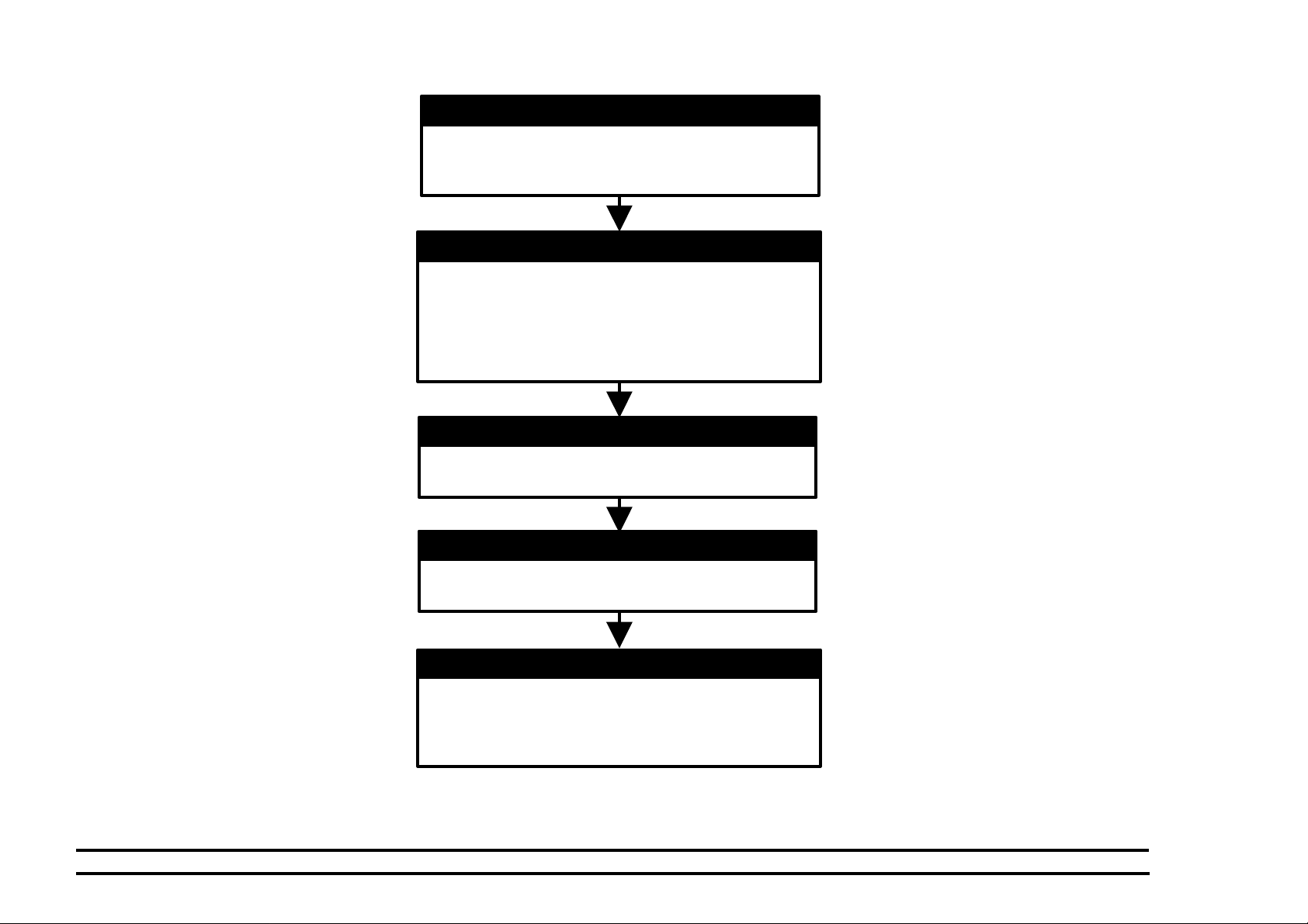
Call Flow
The call flow chart shows you how to conduct
the service call.
Initial Actions
The initial actions suggests how to collect data
necessary to proceed with the service call.
System Checks
The System Checks procedures details the
steps for effective repair and verification of
repair of problems found in Initial Action.
Every Call Activities
These are cleaning and maintenance activities
which are performed on every call.
Scheduled Maintenance
Scheduled Maintenance consists of checking
the life remaining on the CRUs.
Final Action
Final Action ensures that image quality is
acceptable, and that printer performance and
appearance is satisfactory. Details are
included for completing administrative tasks
and closing out the service call.
Section 2 - STATUS INDICATOR REPAIR
ANALYSIS PROCEDURES (RAPs)
This section contains the Repair Analysis
Procedures (RAPs) necessary to repair faults
other than image quality faults.
Section 3 - IMAGE QUALITY REPAIR
ANALYSIS PROCEDURES (RAPs)
This section contains the Repair Analysis
Procedures (RAPs) necessary to repair image
quality faults.
Section 4 - REPAIR/ADJUSTMENT
PROCEDURES
This section contains the Repair and
Adjustment procedures for the printer. All
unique procedures will be identified as follows:
• USCO
• XE
Section 5 - PARTS LIST
This section contains exploded view drawings
and referenced replaceable parts lists for the
Printer.
Section 6 - GENERAL PROCEDURES
This section contains Diagnostic procedures,
Menus, Product Specifications, ESS/IOT test
patterns, and other General Procedures.
Section 7 - WIRING DATA
This section contains Block Schematic
Diagrams (BSDs), Plug/Jack/PWB Location
Diagrams and wiring diagrams.
2/99
ii DocuPrint C55/C55mp/[NC60]
Page 7
INTRODUCTION
HOW TO USE THIS MANUAL
GND
A/D
Section 1, Service Call Procedures will direct
you to each section of the manual necessary
to perform a service call.
You will begin with Initial Actions which
suggest how to collect problem symptoms and
evidence to be used in the next section, the
System Checks Section.
Details in the System Checks are designed to
assist you in classifying, repairing and verifying
the repair of the problem. From here, you may
be directed to any of the other six sections of
the service manual depending on the
symptoms observed and the results of
suggested tests. After a repair has been
verified (or during a repair activity) instructions
are included to direct you into Every Call
Activities.
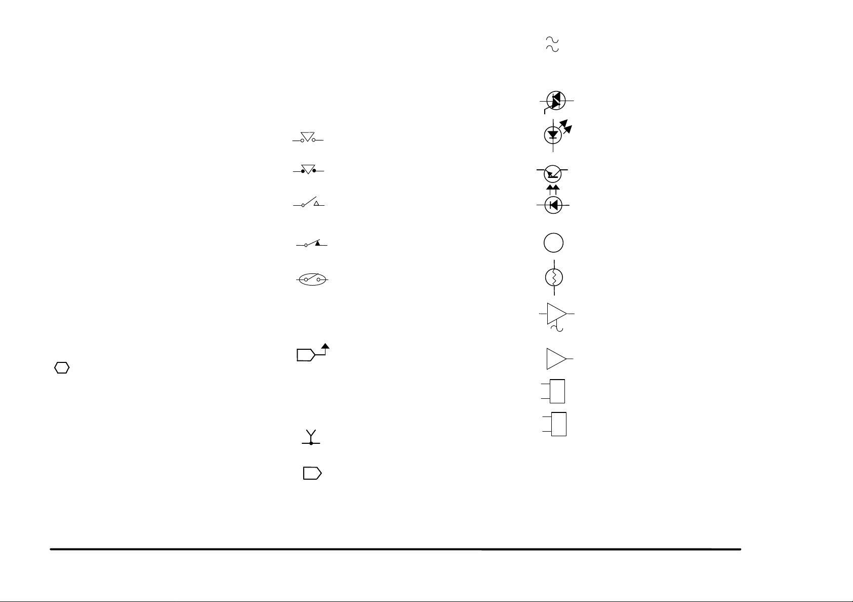
Descriptions of commonly used graphic
symbols are included in order to aid
troubleshooting when using the circuit
diagrams.
Switches/Relays
Safety interlock switch, circuit open.
Safety interlock switch, circuit closed.
Switch/relay with momentary contacts
shown normally open.
Switch/relay with momentary contacts
shown normally closed.
MOT
This symbol, used with a number,
indicates that the actual number may
be equal to or very near the value of
the designated number.
Triac, used to switch AC power.
Light Emitting Diode (LED).
Led/Phototransistor Sensor.
Motor.
REFERENCE SYMBOLOGY
Reference Symbology provides supportive
data for Repairs, Adjustments, and the RAPs.
The symbols that refer to this supportive data
are shown in the paragraphs that follow.
Note:
1
Parts Lists
PL 2.4 (example)
In the example above, the parts list reference
and the exploded view drawing would be found
in Section 5 on sub-section 2.4.
This symbol is used to refer to notes,
usually found on the same page.
Magnetically actuated Switch.
Miscellaneous Symbols
2
A flag that identifies a wire that has
been referred to in the text.
[ 8-2 ] Indicates a Diagnostic Code used to
check a particular component.
Identifies a test point, test hole or test
stake on a PWB.
A
Auditron/Key Counter connection.
2/99
Thermistor Bead, used to sense
temperature.
A Driver which is used to switch on
DC Components.
Analog to Digital Converter.
RL
Relay
Solenoid
DocuPrint C55/C55mp/[NC60] iii
Page 8
INTRODUCTION
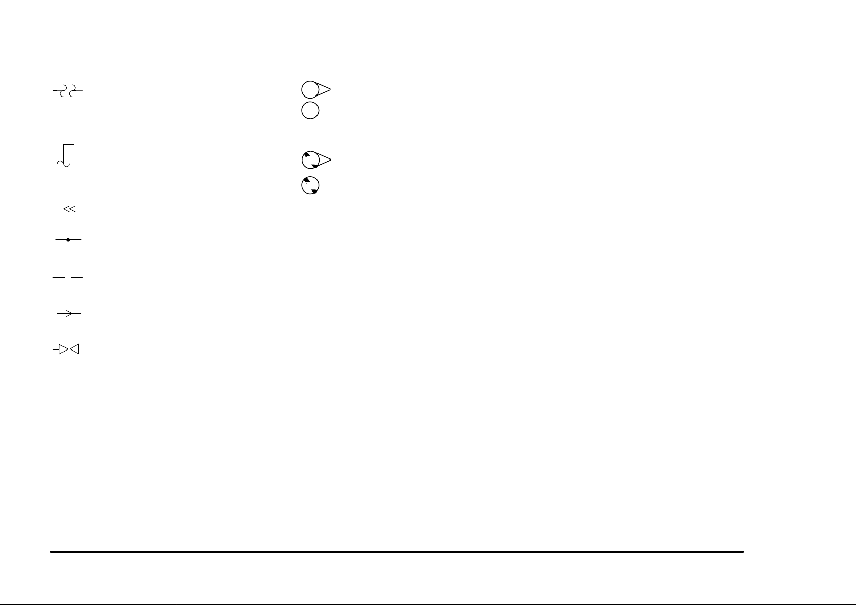
Signal Continuation/Flow
47
47
Tag Identification
Indicates the continuation of a signal
line interrupted in a horizontal
direction.
Represents the continuation of a
standby power line interrupted in the
vertical direction. In all cases, the
supply is from Standby Power
Indicates a feedback signal.
Indicates a common splice of wires.
Indicates a common splice of wires at
a pin.
Indicates the direction of signal flow.
Indicates that the wire continues to
the adjacent page.
47
This WITH TAG Symbol is used to
identify the components or configura-
47
tion that are part of a printer change
covered by the Tag number.
This WITHOUT TAG Symbol is used
to identify the components or
configuration that are not part of a
printer change covered by the Tag
number
2/99
iv DocuPrint C55/C55mp/[NC60]
Page 9

TITLE PAGE
CALL FLOW---------------------------------------1-2
INITIAL ACTION ---------------------------------1-3
SYSTEM CHECKS ------------------------------1-3
EVERY CALL ACTIVITIES --------------------1-4
SCHEDULED MAINTENANCE---------------1-4
FINAL ACTION-----------------------------------1-5
1. SERVICE CALL PROCEDURES
2/99 SERVICE CALL PROCEDURES
DocuPrint C55/C55mp/[NC60] 1-1 SECTION CONTENTS
Page 10
CALL FLOW
INITIAL ACTION
This step is used to gather information about the
reason for the call, to determine the machine
condition, and to run print samples.
SYSTEM CHECKS
This step is used to suggest a direction for using the
information, obtained during Initial Action. You can
then repair and verify the repair of the problem. This
step may also provide information to assist in the
identification of new problems and suggest actions to
take to repair/resolve them.
EVERY CALL ACTIVITIES
This step consists of every call cleaning and
maintenance activities.
SCHEDULED MAINTENANCE
This step is used to check the life remaining on the
CRU’s.
FINAL ACTIONS
This step is used to ensure that the print quality, the
printer performance, and the printer appearance is
satisfactory. It will also provide direction to help
complete administrative tasks.
SERVICE CALL PROCEDURES 2/99
CALL FLOW 1-2 DocuPrint C55/C55mp/[NC60]
Page 11

INITIAL ACTION
Purpose
To suggest how to gather information about
the service call, the machine condition, and to
direct the user through the call.
PROCEDURE
1. Ask the customer to describe the problem
that causes the service call and the job
being run when the problem occurred.
2. Inspect any rejected prints for evidence of
defects.
3. Switch the printer power Off/On and check
for and note/record any fault codes in the
Control Panel Display.
4. Examine the Machine Service Log (under
the Left Side Cover) for previous problems
or activities that may be related to this
service call.
5. Go to (SYSTEM CHECKS).
SYSTEM CHECKS
Purpose
To suggest a direction for effective repair and
verification of repair of problems found in Initial
Action.
PROCEDURE
1. Select the appropriate situation from a-g
below, then diagnose and repair the
problem.
a. Replace any obviously broken parts.
b. If this is an Image Quality problem, go
to IQ1 Image Quality Entry RAP in
Section 3.
c. If there is a Fault Code, go to Section
2 Table of Contents. Locate and
perform the RAP associated with the
Fault Code.
d. If there is NO fault code associated
with the problem, go to Section 2
Table of Contents. Locate and
perform the RAP which most closely
matches the problem described by the
customer.
e. If the problem is not repeatable,
operate the printer in the same job
conditions the customer used and
recheck for a problem in the
categories listed here.
f. If the problem still is not reproduced,
check the printer Fault History.
(C55/C55mp)
Off Line, Menu, then scroll to
<SERVICE>, <ERROR LOGS>,
<FAULT HISTORY>. Scroll through
the Fault History and note any
repeating faults. Refer to the RAP for
these fault codes in Section 2 and
read the fault code description to see
if the code relates to the customer
problem. If so, perform the RAP
[NC60]
Menu Up until Print Menu. Item Up
until Fault History then press Enter.
Look through the Fault History and
note any repeating faults. Refer to the
RAP for these fault codes in Section 2
and read the fault code description to
see if the code relates to the customer
problem. If so, perform the RAP.
g. If none of the above situations applies
go to EVERY CALL ACTIVITIES.
2. Verify that the problem is corrected and go
to EVERY CALL ACTIVITIES.
2/99 SERVICE CALL PROCEDURES
DocuPrint C55/C55mp/[NC60] 1-3 INITIAL ACTION/SYSTEM CHECKS
Page 12

EVERY CALL ACTIVITIES
Purpose
To list service activities required for specific
subsystems.
PROCEDURE
1. Open the printer and Clean the Charge
Scorotron using the Scorotron cleaner.
2. Clean the toner loading area.
3. Remove the Following:
a. Print Drum Module. (GP I)
b. Color Developer Module. (GP 2)
c. Black Developer Module (GP 3)
d. Toner Collector. (GP 4)
4. Vacuum the Drum, Developer, and Toner
Collector areas.
5. Replace the Toner Collector if required.
6. Reinstall the following:
a. Black Developer Module (GP 3)
b. Color Developer Module. (GP 2)
SCHEDULED MAINTENANCE
Purpose
To check the life remaining on the CRUs.
PROCEDURE
1. Check the life of the Customer Replaceable Units (CRUs).
a. (C55/C55mp)
Enter the Off Line mode, press Menu
and scroll to <MAINTENANCE>.
[NC60]
Menu Up until Service Menu, Item Up
until CRU Usage, Value Up to see %
remaining on the CRUs.
b. Check the life remaining on the
following:
• Black Developer Cartridge.
• Color Developer Cartridge.
• Print Drum.
• Fuser Module.
2. If any of the CRUs are near end of life,
notify the customer.
c. Print Drum Module. (GP I)
d. Toner Collector. (GP 4)
7. Use Film Remover to clean the Feed
Rollers. Do not rotate the Feed Rollers
more than 270° while cleaning. Apply
Rubber restore if available.
8. Check the Transfer Drum Nip Adjustment
(ADJ 11.1)
9. Wipe the outside of the printer.
SERVICE CALL PROCEDURES
EVERY CALL ACTIVITIES/ 2/99
SCHEDULED MAINTENANCE 1-4 DocuPrint C55/C55mp/[NC60]
Page 13

FINAL ACTION
Purpose
To ensure the image quality is acceptable,
printer performance and appearance is
satisfactory and to complete administrative
tasks.
PROCEDURE
1. Install/close all covers and doors.
2. Run the Print Quality sample set.
a. (C55/C55mp)
Enter the Off Line mode, press Menu
and scroll to <SERVICE>. Select
<TEST PATTERNS>, and print the
PQ set.
[NC60]
Menu Up until Service Menu, Item
Down until Print PQ Set and press
Enter.
3. If possible, ask the customer to print one
of their representative prints to examine
and comment on.
Wrap-Up Procedure
1. Record your service activities in the
service log.
2. Record the Total meter reading (from the
Diagnostic Test Pattern) in the service log.
3. Record the ESS software level (from the
Diagnostic Test Pattern) in the service log.
4. (C55/C55mp)
(Off Line, Print, Settings). Record the NIC
software level (from the Settings page) in
the service log.
5. Put the Printer PQ set and service log into
the service log folder.
NOTE: It is very important to save the PQ
set. There is information on the Diagnostic
sheet (Toner Concentration setpoints) which
will be needed if the NVM is reset or the PCU
PWB is replaced.
2/99 SERVICE CALL PROCEDURES
DocuPrint C55/C55mp/[NC60] 1-5 FINAL ACTION
Page 14

Notes:
SERVICE CALL PROCEDURES 2/99
NOTES 1-6 DocuPrint C55/C55mp/[NC60]
Page 15

2. STATUS INDICATOR RAPs
TITLE PAGE
TROUBLESHOOTING TIPS ------------------2-2
C1-CHECK TRAY 1 -----------------------------2-3
C2-CHECK TRAY 2 -----------------------------2-3
E1-TRAY 1 JAM----------------------------------2-4
E2-TRAY 2 JAM ---------------------------------2-5
E3-BYPASS JAM --------------------------------2-5
E4-INPUT JAM -----------------------------------2-6
E5 FUSER JAM ----------------------------------2-7
E6-DRUM JAM -----------------------------------2-8
E7-PRINT DRUM JAM------------------------2-10
E8-OUTPUT JAM------------------------------2-10
E9-CLOSE PRINTER-------------------------2-10
EA-COLOR DEV. MISINSTALLED--------2-11
EB-BLACK DEV. MISINSTALLED---------2-11
EC-PRINT DRUM MISINSTALLED--------2-11
F1-DISK ERROR (FLOPPY) ----------------2-12
F2-DISK I/O ERROR (FLOPPY) -----------2-12
F3-ACTION FAILED (FLOPPY) ------------2-12
H1-HARD DISK ERROR---------------------2-13
H2-HARD DISK CONTROLLER
ERROR -------------------------------------2-13
H3-HARD DISK FULL-------------------------2-14
H4-FORMAT HARD DRIVE-----------------2-14
TITLE PAGE
J1-ADD YELLOW TONER-------------------2-15
J2-ADD MAGENTA TONER ----------------2-16
J3-ADD CYAN TONER-----------------------2-17
J4-ADD BLACK TONER ---------------------2-18
J5-REPLACE COLOR DEVELOPER
CARTRIDGE--------------------------------2-19
J6-REPLACE BLACK DEVELOPER
CARTRIDGE--------------------------------2-19
J7-TONER COLLECTOR FULL------------2-20
J8-REPLACE PRINT DRUM----------------2-20
J9-REPLACE FUSER MODULE -----------2-20
JA-REPLACE OIL/PAD-----------------------2-21
T0-FUSER THERMISTOR ERROR-------2-21
T1- UNDER TEMPERATURE --------------2-22
T2- OVER TEMPERATURE ----------------2-23
U0-IOT ROM ERROR ------------------------2-23
U1-IOT RAM ERROR-------------------------2-24
U2-IOT NVM RAM ERROR -----------------2-24
U3-IOT/ESS COMMUNICATION
ERROR -------------------------------------2-24
U4-OPTICS FAULT ---------------------------2-25
U5-POLYGON MOTOR FAULT------------2-25
U6-MOTOR FAULT (DEVELOPER) ------2-26
U7- MOTOR FAULT (MAIN) ----------------2-27
TITLE PAGE
W1-COLOR DEVELOPER MODULE
(NEAR END OF USE)-------------------2-28
W2-BLACK DEVELOPER MODULE
(NEAR END OF USE)-------------------2-28
W3-PRINT DRUM (NEAR
END OF USE)-----------------------------2-28
W4-FUSER MODULE
(NEAR END OF USE)-------------------2-29
W5-FUSER OIL BOTTLE/PAD
(NEAR END OF USE)-------------------2-29
OF1 DEAD PRINTER RAP ---------------- 2-30
OF2 CONTROL PANEL RAP ------------- 2-32
OF3 TRAY 1 PAPER SIZE
SENSING RAP-------------------------2-35
OF4 TRAY 2 PAPER SIZE
SENSING RAP-------------------------2-36
OF5 LOAD PAPER RAP--------------------2-37
OF6AESS RAP (C55/C55mp)--------------2-38
OF6BESS RAP [NC60]-----------------------2-39
OF7 ESS BOOT FAILURE
ERROR CODES [NC60] -------------2-40
OF8 ARCING RAP---------------------------2-41
2/99 STATUS INDICATOR RAPs
DocuPrint C55/C55mp/[NC60] 2-1 SECTION CONTENTS
Page 16
TROUBLESHOOTING TIPS
The following are some general troubleshooting tips and hints which will help you
locate components and test points.
1. The procedures for entering, exiting and
using the C55/C55mp/[NC60] diagnostic
programs can be found in Section 6,
General Procedures. Refer to the Table of
Contents found on page 6-1 for the
specific program.
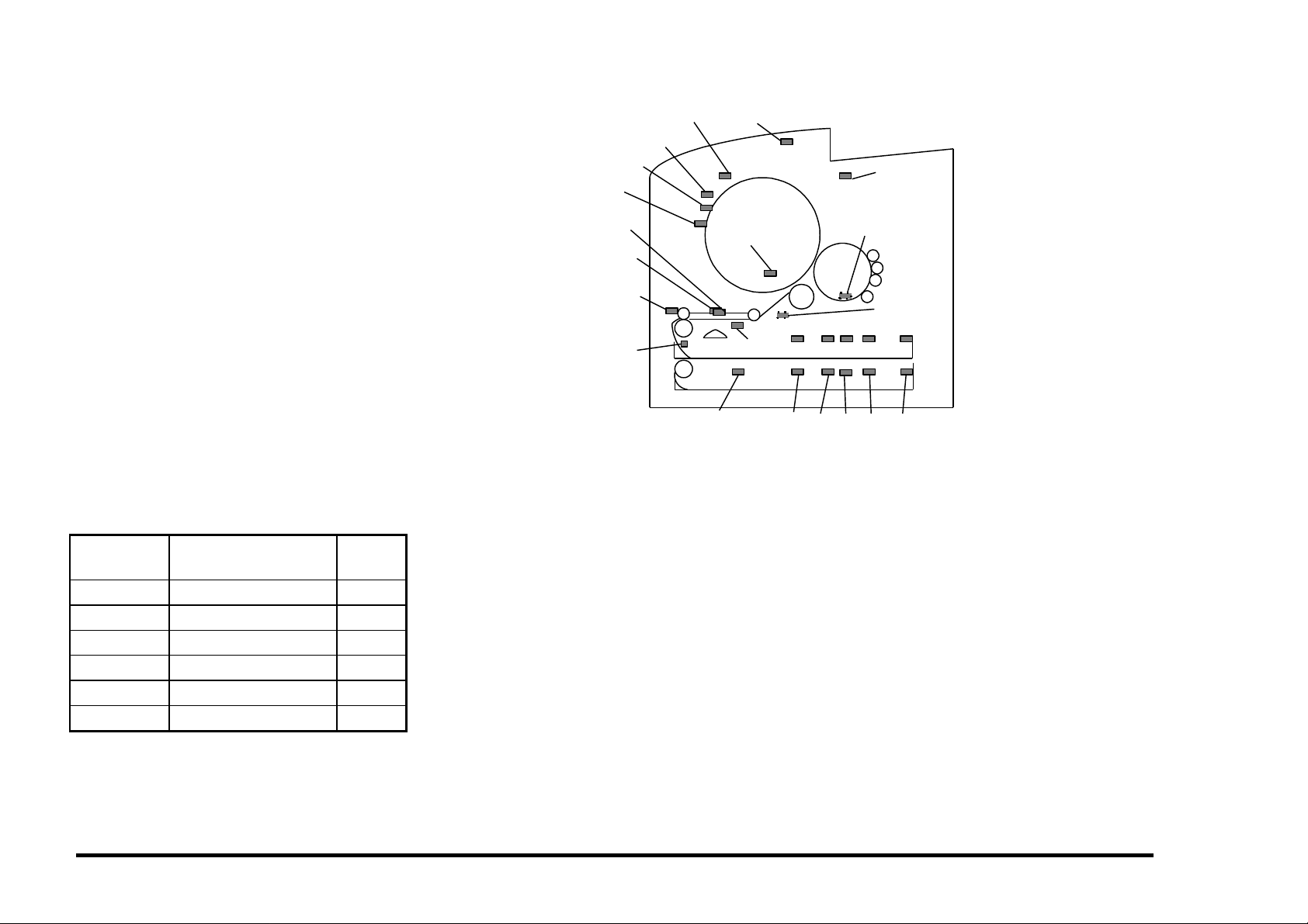
2. Figure 2-1 on the right is also located in
Section 6 and shows the location of the
input electrical components in the printer.
It is especially helpful when using the
Switch Scan program. Refer to this figure
if you are unsure of input component
location. The BSDs in Section 7 may also
prove helpful when locating the various
electrical components.
3. The Connectors can be located in
Section 7. Refer to Section 7 Table of
contents on page 7-1. The table below
shows the location of the most common
connectors:
TRANSPARENCY
JAM SENSOR
CLEANER JAM
SWITCH
TRANSPARENCY
SENSOR
REGISTRATION
SENSOR
BYPASS SWITCH
TEMPERATURE/
HUMIDITY SENSOR
OIL
GAMMA
SENSOR
SENSOR
EXIT SENSOR
TRANSFER DRUM
HOME SENSOR
TRAY EMPTY
SENSOR
T2 TRAY EMPTY
SENSOR
PS0
T2
S0
PS1 PS2 PS3
T2
T2
S1
S2
+24 V
INTERLOCK
SWITCH
PHOTORECEPTOR
DETECT
WASTE TONER
BOTTLE SENSOR
PS4
T2
T2
S4
S3
Figure 2-1. Input Component Location
Connector
Numbers
Location Figure
CN100’s PCU PWB/ESS PWB 7-1
CN200’s Cassette PWB 7-4
CN300’s Connector PWB 7-2
CN400’s Control Panel PWB 7-2
CN700’s LVPS PWB 7-2
CN800’s HVPS PWB 7-3
STATUS INDICATOR RAPs 2/99
TROUBLESHOOTING TIPS 2-2 DocuPrint C55/C55mp/[NC60]
Page 17

C1 CHECK TRAY 1 RAP
Cassette 1 is not in the printer.
INITIAL ACTION
Load paper and insert Cassette 1 into the
printer.
Switch the power off wait 10 seconds and
switch the power on. Recheck for the fault.
PROCEDURE
Enter IOT normal diagnostics. Scroll to the
SWITCH SCAN program and select Scan Row
01, Press Form Feed [1].
Remove Cassette 1. Manually make and
break Paper Size Sensor 0 while observing the
Cyan LED. (Sensor 0 is the first one on the
left when viewed from the front of the printer.)
The Cyan LED switches on and off.
Y N
Go to BSD 7.2 in Section 7 and troubleshoot the Paper Size 0 Sensor signal
(CN107-8) for a short to ground.
If no short is found, replace the PCU
PWB. If the problem still exists, replace
the Cassette PWB.
Check for a broken Sensor Flag on the Tray 1
Cassette.
If the problem still exists, replace the PCU
PWB. If the problem still exists, replace the
Cassette PWB.
C2 CHECK TRAY 2 RAP
Cassette 2 is not in the printer.
INITIAL ACTION
Move the length stop to the 11 inch position
(Figure 2-2), load paper, and insert Cassette 2
into the printer.
Switch the power off wait 10 seconds and
switch the power on. Recheck for the fault.
PROCEDURE
Enter IOT normal diagnostics. Scroll to the
SWITCH SCAN program and select Scan Row
03. Press Form Feed [1].
Remove Cassette 2. Manually make and
break T2 Paper Size Sensor 0 while observing
the Cyan LED.
The Cyan LED switches on and off.
Y N
Refer to BSD T2, 7.2 in Section 7 and
check the following:
• T2 Paper Size 0 Sensor signal CN109-
1 for an open.
• +5 VDC CN109-5
If no problem is found, replace the PCU
PWB. If the problem still exists, replace
the T2 Cassette PWB.
Check for a broken Sensor Flag on the Tray 2
Cassette.
If the problem still exists, replace the PCU
PWB. If the problem still exists, replace the
Cassette PWB.
14"10.5" 11", A4
Figure 2-2. Length Stop Location
2/99 STATUS INDICATOR RAPs
DocuPrint C55/C55mp/[NC60] 2-3 C1, C2
Page 18

E1 TRAY 1 JAM RAP
Paper fed from Tray 1 did not reach the
Registration Sensor.
INITIAL ACTION
Remove the cassette and check that the paper
is loaded correctly and is in good condition.
Switch the power off wait 10 seconds and
switch the power on. Recheck for the fault.
PROCEDURE
Check the following:
• Obstructions in the paper path.
• Dirty Feed Rolls.
• Dirty Drive Rollers.
• Mechanical drive problem.
Enter IOT normal diagnostics. Scroll to the
SWITCH SCAN program and select Scan Row
00. Press Form Feed [1].
Open the Printer. Actuate and deactuate the
Registration Sensor while observing the
Magenta LED.
The Magenta LED switches on and off.
Y N
Go to BSD 8.1 in Section 7 and troubleshoot the Registration Sensor signal, +5
VDC and GND (CN102-9, 7, 8) for an
open.
If no open exists, replace the PCU PWB.
If the problem still exists, replace the
Registration Sensor.
Press Media Server [2]. Select Scan Row 01.
Press Form Feed [1].
Remove the cassette and actuate and
deactuate the Tray Empty Sensor while
observing the Black LED.
A
A
The Black LED switches on and off.
Y N
Go to BSD 7.1 in Section 7 and troubleshoot the Tray Empty Sensor signal
(CN102-6) for a short to ground.
If no short exists, replace the PCU PWB. If
the problem still exists, replace the Tray
Empty Sensor.
Exit from the SWITCH SCAN program.
Close the Printer.
Remove the paper cassette. Scroll to the
MOTOR TEST program. Press Form Feed
[1] to switch on the motors while observing the
Paper Feed Motor.
The Paper Feed Motor is rotating normally.
Y N
Go to BSD 7.3 in Section 7 and trouble-
shoot the +24 VDC Interlocked (CN111-5)
and Paper Feed Motor for an open. If the
motor was noisy, check the clock lines.
If the lines are OK, replace the PCU PWB.
If the problem still exists, replace the
Paper Feed Motor.
Exit from diagnostics.
Set up the meter to read +24 VDC. Measure
between CN101-5 (+) and ground (−).
Make one print while monitoring the meter.
The meter swings from +24 VDC to 0.
Y N
Go to BSD 7.4 in Section 7 and trouble-
shoot the Feed Solenoid signal, and +24
VDC Interlocked (CN101-5, 3) for an
open.
B C
B C
If no open exists, replace the PCU PWB. If
the problem still exists, replace the Paper
Feed Solenoid.
Check for a mechanical problem with the feed
clutch.
STATUS INDICATOR RAPs 2/99
E1 2-4 DocuPrint C55/C55mp/[NC60]
Page 19

E2 TRAY 2 JAM RAP
Paper fed from Tray 2 did not reach the
Registration Sensor.
INITIAL ACTION
Remove the cassette and check that the paper
is loaded correctly and is in good condition.
Check the position of the rear stop.
Make sure that Tray 1 is pushed all the way in.
Switch the power off wait 10 seconds and
switch the power on. Recheck for the fault.
PROCEDURE
Try to run a print from Tray 1.
The print feeds OK from Tray 1.
Y N
Go to E1 TRAY 1 JAM RAP.
Check the following:
• Obstructions in the paper path.
• Dirty Feed Rolls.
• Dirty Drive Rollers.
• Mechanical drive problem.
Enter IOT normal diagnostics. Scroll to the
SWITCH SCAN program and select Scan Row
03. Press Form Feed [1].
Remove cassette 2. Actuate and deactuate
the Tray 2 Empty Sensor while observing the
Black LED.
The Black LED switches on and off.
Y N
Go to BSD T2 7.1 in Section 7 and
troubleshoot the T2 Tray Empty Sensor
signal (CN109-4) for a short to ground.
If no short exists, replace the PCU PWB.
If the problem still exists, replace the Tray
2 Empty Sensor.
A
A
Exit from diagnostics.
Set up the meter to read +24 VDC. Measure
between CN109-8 (+) and ground (−).
Make one print while monitoring the meter.
The meter swings from +24 VDC to 0 and
back to +24.
Y N
Go to BSD T2 7.3 in Section 7 and
troubleshoot the T2 Feed Solenoid signal,
and +24 VDC Interlocked (CN109-8, 7) for
an open.
If no open exists, replace the PCU PWB. If
the problem still exists, replace the T2
Feed Solenoid.
Measure between CN109-9 (+) and ground
(−).
Make one print while monitoring the meter.
The meter swings from +24 VDC to 0 and
back to +24.
Y N
Go to BSD T2 7.4 in Section 7 and
troubleshoot the T2 Drive Clutch signal
(CN109-9) for an open.
If no open exists, replace the PCU PWB.
If the problem still exists, replace the T2
Drive Clutch.
Check for a mechanical problem with the Feed
Clutch and Drive Clutch
E3 BYPASS JAM RAP
Paper fed from the Bypass Tray did not reach
the Registration Sensor.
INITIAL ACTION
Carefully inspect the bypass opening for
paper.
Switch the power off wait 10 seconds and
switch the power on. Run another print and
recheck for the fault.
PROCEDURE
If paper does not feed from the Bypass but
does feed from Tray 1, check for an
obstruction in the bypass slot.
Check to ensure that the switch is installed
correctly and has not fallen out.
If no paper is loaded in the Bypass when the
E3 occurs, refer to BSD 7.5 in Section 7 and
check the Bypass Switch signal (CN312-2) for
a short to ground.
If no short exists, replace the PCU PWB. If
the problem still exists, replace the Bypass
Switch.
2/99 STATUS INDICATOR RAPs
DocuPrint C55/C55mp/[NC60] 2-5 E2, E3
Page 20

E4 INPUT JAM RAP
Paper was on the Registration Sensor too
long.
INITIAL ACTION
Open the printer and check for any obstruction
in the register roller area.
Switch the power off wait 10 seconds and
switch the power on. Run another print to
recheck for the fault.
Make sure the Grounding Roller is rotating
freely.
Perform the Transfer Drum Nip Adjustment
(ADJ 11.1)
PROCEDURE
Enter IOT normal diagnostics. Scroll to the
SWITCH SCAN program and select Scan Row
00. Press Form Feed [1].
Open the Printer. Actuate and deactuate the
Registration Sensor while observing the
Magenta LED.
The Magenta LED switches on and off.
Y N
Go to BSD 8.1 in Section 7 and troubleshoot the Registration Sensor signal
(CN102-9) for a short to ground.
If no short exists, replace the PCU PWB.
If the problem still exists, replace the
Registration Sensor.
Press Media Server [2]. Select Scan Row 04.
Press Form Feed [1].
Actuate and deactuate the Transparency
Sensor while observing the Cyan LED.
A
A
The Cyan LED switches on and off.
Y N
Go to BSD 8.4 in Section 7 and trouble-
shoot the Transparency Sensor signal
(CN311-1) for a short to ground.
If no short exists, replace the PCU PWB.
If the problem still exists, replace the
Transparency Sensor.
Exit from the SWITCH SCAN program.
Close the Printer.
Remove the paper cassette. Scroll to the
MOTOR TEST program and press Form Feed
[1] to switch on the motors while observing the
Paper Feed Motor.
The Paper Feed Motor is rotating normally.
Y N
Go to BSD 7.3 in Section 7 and trouble-
shoot the Paper Feed Motor clock lines.
If the lines are OK, replace the PCU PWB.
If the problem still exists, replace the
Paper Feed Motor.
Exit from diagnostics.
Set up the meter to read +24 VDC. Measure
between CN103-4 (+) and ground (−).
Make one print while monitoring the meter.
The meter swings from +24 VDC to 0 and
back to +24.
Y N
Go to BSD 9.16 in Section 7 and trouble-
shoot the Stripper Solenoid signal and +24
VDC Interlocked (CN103-4, CN303-2,1) for
an open.
If no open exists, replace the PCU PWB. If
the problem still exists, replace the
Stripper Solenoid.
B
B
Set up the meter to read +24 VDC. Measure
between CN101-5 (+) and ground (−).
Make one print while monitoring the meter.
The meter swings from +24 VDC to 0 and
back to +24.
Y N
Go to BSD 7.4 in Section 7 and troubleshoot the Feed Solenoid signal (CN101-5)
for a short to ground.
If no short exists, replace the PCU PWB.
If the problem still exists, replace the Feed
Solenoid.
Set up the meter to read +24 VDC. Measure
between CN101-4 (+) and ground (−).
Make one print while monitoring the meter.
The meter swings from +24 VDC to 0 and
back to +24.
Y N
Go to BSD 8.2 in Section 7 and troubleshoot the Registration Clutch signal and
+24 VDC Interlocked (CN101-4, 1) for an
open.
If no open exists, replace the PCU PWB. If
the problem still exists, replace the
Registration Clutch.
Check the following:
• Obstructions torn paper etc. in the paper
path.
• Mechanical drive problem.
STATUS INDICATOR RAPs 2/99
E4 2-6 DocuPrint C55/C55mp/[NC60]
Page 21

E5 FUSER JAM RAP
Paper did not reach the Exit Sensor.
INITIAL ACTION
Open the Printer and remove the Fuser
Assembly. Check for any obstructions in the
fuser paper path.
Switch the power off wait 10 seconds and
switch the power on. Run another print to
recheck for the fault.
PROCEDURE
Check the following:
• Obstructions in the paper path.
• Defective stripper fingers.
• Mechanical drive problem.
Enter IOT normal diagnostics. Scroll to the
SWITCH SCAN program and select Scan Row
00. Press Form Feed [1].
Open the Printer, then open the Fuser cover.
Actuate and deactuate the Exit Sensor while
observing the Yellow LED.
The Yellow LED switches on and off.
Y N
With SCAN ROW 00 still selected, actuate
and deactuate the Bypass Switch while
observing the Cyan LED.
The Cyan LED switches on and off.
Y N
Go to BSD 10.2 and troubleshoot the
Strobe 2 signal CN103-18 for an open.
If no open exists replace the PCU
PWB.
A B
A B
Go to BSD 10.2 in Section 7 and troubleshoot the Exit Sensor signal, +5 VDC and
GND (CN308-1, 3, 2) for an open.
If no open exists, replace the PCU PWB.
If the problem still exists, replace the Exit
Sensor.
Exit from the SWITCH SCAN program.
Remove the Front Cover and then close the
Printer.
Scroll to the MOTOR TEST program and
press Form Feed [1] to switch on the motors
while observing the Fuser Drive Motor.
The Fuser Drive Motor is rotating normally.
Y N
Go to BSD 10.1 in Section 7 and trouble-
shoot the Fuser Drive Motor clock lines.
If the lines are OK, replace the PCU PWB.
If the problem still exists, replace the
Fuser Drive Motor.
• Make sure the Fuser Cover fits correctly.
• Check for a Mechanical problem.
2/99 STATUS INDICATOR RAPs
DocuPrint C55/C55mp/[NC60] 2-7 E5
Page 22

E6 DRUM JAM RAP
Paper is jammed on the Transfer Drum and
could be caused by one of the following:
• Transfer Drum Cleaner not cleaning the
Transfer Drum or resting on the Transfer
Drum during the Print cycle.
• Paper did not reach the Gamma Sensor.
• Paper did not tack to the Transfer Drum and
actuated the Transparency Jam Sensor.
• Paper did not tack to the Transfer Drum
and actuated the Cleaner Jam Switch.
• Arcing between the Charge Scorotron
connectors and the Print Drum.
INITIAL ACTION
Open the Printer and check for torn paper or
an obstruction in the paper path. Check for a
sheet of paper or a transparency actuating the
Transparency Jam Sensor or the Cleaner Jam
Switch.
Check the Toner Collector for “layered” toner
(sand-art effect). If layered toner is present,
refer to OF8 Arcing RAP.
If the problem only occurs when running color
prints, check the Stripper Fingers for binding
or interference.
Open the Printer and position the Transfer
Drum Home Position Sensor flag at the
3 o’clock position. The Lead edge of the white
patch should be at the tips of the stripper
fingers. If not, replace the Transfer Drum.
PROCEDURE
Switch the Printer off. Remove the front cover
and tape the Control Panel up so that you can
view the operation of the Transfer Drum
Cleaning Solenoid.
Switch the Printer on. Observe the Transfer
Drum Cleaning Solenoid and the Cleaner
Assembly.
If you see solid development during the copy
quality setup, go the OF8 Arcing RAP.
The Transfer Drum Cleaning Solenoid should
energize and move the Cleaner Assembly
against the Transfer Drum while the patches
are generated during the Copy Quality Setup.
When the Copy Quality Setup is complete the
Transfer Drum Cleaning Solenoid should
deenergize and move the Cleaner Assembly
away from the Transfer Drum.
If the E6 jam occurs before paper is fed and
the patches are not being cleaned the Transfer
Drum Cleaner assembly is not camming into
the cleaning position.
If the machine prints OK when printing black
only but jams (E6) when printing color, it is an
indication that the Transfer Drum Cleaner
assembly is staying cammed against the
Transfer Drum.
The Transfer Drum Cleaning Solenoid and
Transfer Drum Cleaner Assembly are
operating correctly.
Y N
Check that when the solenoid energizes
the camshaft turns 180 degrees and is
stopped by the outer tab on the cleaner
clutch sleeve. Ensure that the solenoid is
tight and the actuator catches the inner tab
when de-energized, and stops the outer
tab when energized. Check for flashing on
the plastic assembly, a bent solenoid
actuator or other things that could interfere
with proper operation. Clean the cams
and the cam followers with film remover to
minimize friction. Do not attempt to
lubricate these cams. Observe the operation several times and look for smooth,
consistent operation. Do not attempt to
disassemble and adjust the clutch. If the
clutch is defective order the new Cleaner
Clutch Shaft Assembly.
A B
A B
Set up the meter to read +24 VDC. Measure
between CN103-3 (+) and ground (−).
Switch the power off wait 10 seconds and
switch the power on while monitoring the
meter.
The meter swings from +24 VDC to 0
and back to +24.
Y N
Go to BSD 9.14 in Section 7 and
troubleshoot the Transfer Drum
Cleaning Solenoid signal and
+24 VDC Interlocked (CN103-3,
CN316-2, 1) for an open or a short.
If 24 VDC is not available at 316-1 on
the Connector PWB, go to BSD 1 and
troubleshoot the 24 VDC Interlocked
(CN114-1, CN103-1).
Check the Transfer Drum Cleaning
Solenoid and the cleaner assembly for
binding.
If the sheet appears to be stopping at the
Transfer Drum to Print Drum Nip, check the
Transfer Drum Nip Adjustment (ADJ 11.1).
Enter IOT normal diagnostics. Scroll to the
SWITCH SCAN program and select Scan Row
05. Press Form Feed [1].
Open the Printer. Actuate and deactuate the
Transparency Jam Sensor while observing the
Black LED.
The Black LED switches on and off.
Y N
Check for an obstruction that is keeping the
Transparency Jam Sensor actuator raised.
C D
STATUS INDICATOR RAPs 2/99
E6 2-8 DocuPrint C55/C55mp/[NC60]
Page 23

C D
If OK, refer to BSD 9.17 and check the
Transparency Jam Sensor signal CN314-2
for a short to ground.
If no short exists, replace the PCU PWB.
If the problem still exists, replace the
Transparency Jam Sensor.
Open the printer and remove the Transfer
Discharge Corotron from the left side of the
printer. You will need to squeeze the corotron
handle to release the corotron.
With Scan Row 05 still selected, actuate and
deactuate the Cleaner Jam Switch while
observing the Magenta LED.
The Magenta LED switches on and off.
Y N
Check for an obstruction that is keeping
the Cleaner Jam Switch actuated.
If OK, refer to BSD 9.18 and check the
Cleaner Jam Switch signal CN318-2 for a
short to ground.
If no short exists, replace the PCU PWB.
If the problem still exists, replace the
Cleaner Jam Switch.
Exit from the Switch Scan Program.
Scroll to the MOTOR TEST program and
switch on the motors while observing the
Fuser Drive Motor
The Fuser Drive Motor is rotating normally.
Y N
Go to BSD 10.1 in Section 7 and troubleshoot the Fuser Drive Motor for an open.
If the motor was noisy, check the clock
lines for an open or short
If the lines are OK, replace the PCU PWB.
If the problem still exists, replace the
Fuser Drive Motor.
E
E
Set up the meter to read +24 VDC. Measure
between CN103-4 (+) and ground (−).
Make one print while monitoring the meter.
The meter swings from +24 VDC to 0 and
back to +24.
Y N
Go to BSD 9.16 in Section 7 and troubleshoot the Stripper Solenoid signal and +24
VDC Interlocked (CN103-4, CN303-2, 1)
for an open or a short.
If no short or open can be found, replace
the PCU PWB. If the problem still exists,
replace the Stripper Solenoid.
Set up the meter to read +5 VDC. Measure
between CN103-11 (+) and ground (−).
Switch the power off wait 10 seconds and
switch the power on.
The meter swings from 3.8 VDC to .5 when
the white patch passes in front of the
Gamma Sensor.
Y N
Go to BSD 8.5 in Section 7 and troubleshoot
the Gamma Sensor, all lines, for an open.
If the lines are OK, replace the PCU PWB.
If the problem still exists, replace the
Gamma Sensor.
Refer to Section 6, GP 9.3 and perform the
Transfer Voltage Check.
The Transfer voltage is within specification.
F
F
Y N
Go to BSD 9.1 in Section 7 and troubleshoot the following for an open or short.
• Black Transfer Lead from the Power
Supply.
• Transfer On Signal (CN106-3).
• Transfer Control Signal (CN106-5).
• Bias Control Signal (CN106-6).
• +24 VDC to Power Supply (CN106-1).
If no wiring problem can be found, replace
the PCU PWB. If the problem still exists,
replace the High voltage Power Supply.
Refer to BSD 9.1 in Section 7 and check the
Charge On Signal (CN106-2) for an open.
Check the following:
• Obstructions in the paper path.
• Dirty Feed Rolls.
• Mechanical drive problem.
2/99 STATUS INDICATOR RAPs
DocuPrint C55/C55mp/[NC60] 2-9 E6
Page 24

E7 PRINT DRUM JAM RAP
INITIAL ACTION
Open the Printer and clear the jam.
If problem reoccurs refer to E4 RAP.
E8 OUTPUT JAM RAP
Paper was on the Exit Sensor too long.
INITIAL ACTION
We have seen some machines where the
actuator for the Exit Sensor has become stuck
during shipping. When this happens, the
sensor does not change state, and the E8 jam
occurs. If you remove the sensor cover
(PL 2.1) by removing the two screws that
secure it, you can ensure that the actuator is
free and that the sensor is secured in the
proper position in the sensor cover.
Open the Printer and remove the Fuser
Assembly. Check for any obstructions in the
fuser paper path.
Switch the power off wait 10 seconds and
switch the power on. Run another print to
recheck for the fault.
PROCEDURE
Enter IOT normal diagnostics. Scroll to the
SWITCH SCAN program and select Scan Row
00. Press Form Feed [1].
Open the Printer, then open the Fuser Cover.
Actuate and deactuate the Exit Sensor while
observing the Yellow LED.
The Yellow LED switches on and off.
Y N
Go to BSD 10.2 in Section 7 and troubleshoot the Exit Sensor signal (CN308-1) for
a short to ground.
If no short exists, replace the PCU PWB.
If the problem still exists, replace the Exit
Sensor.
Check the following:
• Obstructions in the paper path.
• Mechanical drive problem in the feedout
area.
E9 CLOSE PRINTER RAP
The Printer is open.
INITIAL ACTION
Open and reclose the printer.
PROCEDURE
Enter IOT normal diagnostics. Scroll to the
SWITCH SCAN program and select Scan Row
00. Press Form Feed [1].
Open and close the Printer while observing the
Black LED.
The Black LED switches on and off.
Y N
Go to BSD 1 (G1) in Section 7 and
troubleshoot the 24 VDC Interlock Switch.
If no open exists, replace the PCU PWB.
If the problem still exists, replace the
24 VDC Interlock Switch.
Replace the PCU PWB.
STATUS INDICATOR RAPs 2/99
E7, E8, E9 2-10 DocuPrint C55/C55mp/[NC60]
Page 25

EA COLOR DEV. MISINSTALLED
RAP
The Color Developer Module was installed
incorrectly or overtoning has occurred.
INITIAL ACTION
Enter IOT normal diagnostics. Scroll to the
TEST PRINT program and press Form Feed
[1] to run a test print. While the print is
running, observe the KT=__, CT=__, MT=__,
YT=__ values.
If any of the three color (C, M, Y) toner
concentration values are below 10, that color
is overtoned. Refer to ADJ 9.1 EA “Tone
Down” Procedure in Section 4.
If the values are NOT too low, continue with
this RAP.
Remove the Color Developer Module.
Check the Developer Module connector to be
sure it is clean.
Reinstall the Color Developer Module.
If the problem persists, check connector
CN118 for a good connection or any loose
wiring before replacing the Color Developer
Module.
If the problem still exists, replace the PCU
PWB.
EB BLACK DEV. MISINSTALLED
RAP
The Black Developer Module was installed
incorrectly or the contacts are dirty.
INITIAL ACTION
Remove the Black Developer Module.
Check for binding in the housing.
Check to be sure that the seal has been
removed.
Check the Developer Module connector to be
sure it is clean.
Reinstall the Black Developer Module.
If the problem persists, check connector
CN107 for a good connection or any loose
wiring before replacing the Black Developer
Module.
If the problem still exists, replace the PCU
PWB.
EC PRINT DRUM MISINSTALLED
RAP
The Print Drum Module was installed
incorrectly or is not making a good connection.
INITIAL ACTION
Remove then reinstall the Print Drum Module.
This problem is usually caused by a poor
connection on the left side of the Print Drum
Module. Three contacts are cammed out
when the Print Drum Module is installed.
These contacts make a connection with the
Drum Link PWB located on the left side of the
Print Drum Module. Check to make sure there
is a good connection and the contacts cam
out.
Refer to BSD 9.2 in Section 7 and check the
Drum Detect (H) signal.
If the problem persists, replace the Print Drum
Module.
If the problem still exists, replace the PCU
PWB.
2/99 STATUS INDICATOR RAPs
DocuPrint C55/C55mp/[NC60] 2-11 EA, EB, EC
Page 26

F1 DISK ERROR (FLOPPY) RAP
The Floppy Disk cannot be read.
INITIAL ACTION
Note: The Floppy Disk must be a DOS format.
Load a different floppy and try to read it.
If the floppy still cannot be read, check the
following for a good connection:
• CN102 between the Floppy drive and the
ESS. (BSD 13 in Section 7).
• CN103 the flat cable between the Floppy
drive and the ESS. (BSD 13 in Section 7).
If the problem still exists, replace the Floppy
Drive before replacing the ESS PWB.
F2 DISK I/O ERROR (FLOPPY) RAP
The Floppy Disk cannot be read.
INITIAL ACTION
Note: The Floppy Disk must be a DOS format.
Load a different floppy and try to read it.
If the floppy still cannot be read, check the
following for a good connection:
• CN102 between the Floppy drive and the
ESS. (BSD 13 in Section 7).
• CN103 the flat cable between the Floppy
drive and the ESS. (BSD 13 in Section 7).
If the problem still exists, replace the Floppy
Drive before replacing the ESS PWB.
F3 ACTION FAILED (FLOPPY) RAP
The Floppy Disk cannot be accessed.
INITIAL ACTION
Note: The Floppy Disk must be a DOS format.
Load a different floppy and try to read it.
If the floppy still cannot be read, check the
following for a good connection:
• CN102 between the Floppy drive and the
ESS. (BSD 13 in Section 7).
• CN103 the flat cable between the Floppy
drive and the ESS. (BSD 13 in Section 7).
If the problem still exists, replace the Floppy
Drive before replacing the ESS PWB.
STATUS INDICATOR RAPs 2/99
F1, F2, F3 2-12 DocuPrint C55/C55mp/[NC60]
Page 27

H1 HARD DISK ERROR RAP
The Hard Disk cannot be read.
C55/C55mp
NOTE: If no hard disk is installed on this
printer, print a Settings page (Off Line, Print,
Settings) to record the customer network
settings. Tell the customer that you are going
to do a factory reset and they will need to
reinstall the printer on their network. Perform
a Factory Reset (Off Line, Setup, Factory
Reset).
[NC60]
NOTE: If no hard disk is installed on this
printer, print a Config. sheet (Menu Up to
Service Menu, Item Up to Config Sheet,
Enter) to record the customer network
settings. Tell the customer that you are going
to do a factory reset and they will need to
reinstall the printer on their network. Perform
a Factory Reset. Power Off. Press and hold
On Line and Enter. Switch the power on.
Continue holding the On Line and Enter keys
until the display indicates Power On Version
X.XX, then release the keys. This will enable
the Reset Menu. Menu Up until Reset Menu,
Item Up until Factor Defaults, Value Up until
Yes, then press Enter.
INITIAL ACTION
Switch the power off wait 10 seconds and
switch the power on. This will force the ESS to
retry reading the Hard Disk.
If the Hard Disk still cannot be read, check the
following:
• (C55/C55mp)
Check the Hard Disk to ensure that the
new Relay Interface PWB is installed.
Look for a small PWB mounted to the left
of the hard drive.
• All Printers, check for a good connection
between the Hard Disk and the ESS
(CN101). (BSD 13 in Section 7).
If the problem still exists, replace the Hard
Disk before replacing the ESS PWB.
H2 HARD DISK CONTROLLER
ERROR RAP
The Hard Disk Controller has failed.
INITIAL ACTION
Switch the power off wait 10 seconds and
switch the power on. Retry reading the Hard
Disk.
If the Hard Disk still cannot be read, check the
following for a good connection :
• Between the Hard Disk and the ESS
(CN101). (BSD 13 in Section 7).
If the problem still exists, replace the ESS
PWB.
2/99 STATUS INDICATOR RAPs
DocuPrint C55/C55mp/[NC60] 2-13 H1, H2
Page 28

H3 HARD DISK FULL RAP
The Hard Disk is full.
INITIAL ACTION
Switch the power off wait 10 seconds and
switch the power on. This will force the ESS to
retry reading the Hard Disk.
If the Hard Disk still does not write, have the
customer remove some of the files from the
Hard Disk.
H4 REFORMAT HARD DISK RAP
The Hard Disk needs to be formatted.
INITIAL ACTION
Switch the power off wait 10 seconds and
switch the power on to retry reading the Hard
Disk.
If the H4 occurs again, reformat the hard disk:
STATUS INDICATOR RAPs 2/99
H3, H4 2-14 DocuPrint C55/C55mp/[NC60]
Page 29
J1 ADD YELLOW TONER RAP
The yellow toner concentration sensor has
detected low yellow toner in the yellow
developer assembly. When this occurs, the
Printer will display “Adjusting Print Quality” and
attempt to tone up.
NOTE: If a new color developer housing has
been installed, make sure the 3 seals have
been removed from the left side of the
housing.
INITIAL ACTION
Check with the customer to see if they have
already added Yellow Dry Ink. Add Yellow Dry
Ink, if required.
Adding too much toner can cause the toner to
“cake” and not be dispensed.
(C55/C55mp)
Put the printer in the Off Line mode.
Select the SERVICE Menu and print a
Diagnostic Test Sheet.
Determine the Engine Software version from
the Diagnostic Test Sheet. If the Software
level is Version 66, replace the PCU PWB.
All Printers, switch the power off wait 10
seconds and switch the power on. Allow the
Printer to try to tone up to recheck for the fault.
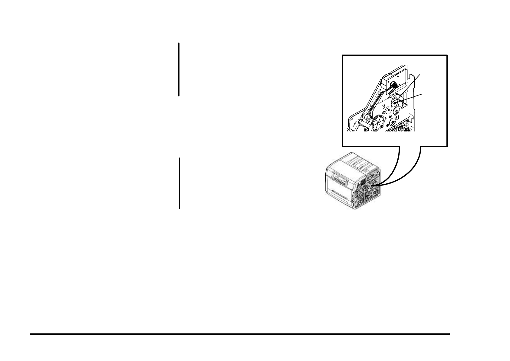
PROCEDURE
Enter IOT normal diagnostics. Scroll to the
MOTOR TEST program and Press Form
Feed [1] to switch on the motors while
observing the Color Toner Motor.
The Color Toner Motor is rotating normally.
A
A
Y N
Refer to BSD 9.11 in Section 7 and
troubleshoot the Color Toner Motor lines
(CN116-1, 2) for an open or a short to
ground.
If no wiring problem exists, replace the
PCU PWB. If the problem still exists,
replace the Color Toner Motor.
Exit from diagnostics .
Set up the meter to read +24 VDC. Measure
between CN115-16 (+) and ground (−).
Switch the power off wait 10 seconds and
switch the power on while monitoring the meter.
The meter swings from +24 VDC to 0.
Y N
Go to BSD 9.10 in Section 7 and trouble-
shoot the Yellow Toner Solenoid signal
and +24 VDC Interlocked (CN115-16, 15)
for an open.
If no open exists, replace the PCU PWB.
If the problem still exists, replace the
Yellow Toner Solenoid.
Check the Yellow Dispense Shaft to see if it
rotates when the Solenoid energizes. If not,
look for a mechanical problem (gears etc.).
Check the ground to the Yellow Toner
Concentration Sensor (CN118-4 to CN1009-7)
BSD 9.10.
If the ground is OK, replace the PCU PWB.
Color
Toner
Motor
Y Disp.
Shaft
01/02
2/99 STATUS INDICATOR RAPs
DocuPrint C55/C55mp/[NC60] 2-15 J1
Page 30
J2 ADD MAGENTA TONER RAP
The magenta toner concentration sensor has
detected low magenta toner in the magenta
developer assembly. When this occurs, the
Printer will display “Adjusting Print Quality” and
attempt to tone up.
NOTE: If a new color developer housing has
been installed, make sure the 3 seals have
been removed from the left side of the
housing.
INITIAL ACTION
Check with the customer to see if they have
already added Magenta Dry Ink. Add Magenta
Dry Ink, if required.
Adding too much toner can cause the toner to
“cake” and not be dispensed.
(C55/C55mp)
Put the printer in the Off Line mode.
Select the SERVICE Menu and print a
Diagnostic Test Sheet.
Determine the Engine Software version from
the Diagnostic Test Sheet. If the Software
level is Version 66, replace the PCU PWB.
All Printers, switch the power off wait 10
seconds and switch the power on. Allow the
Printer to try to tone up to recheck for the fault.
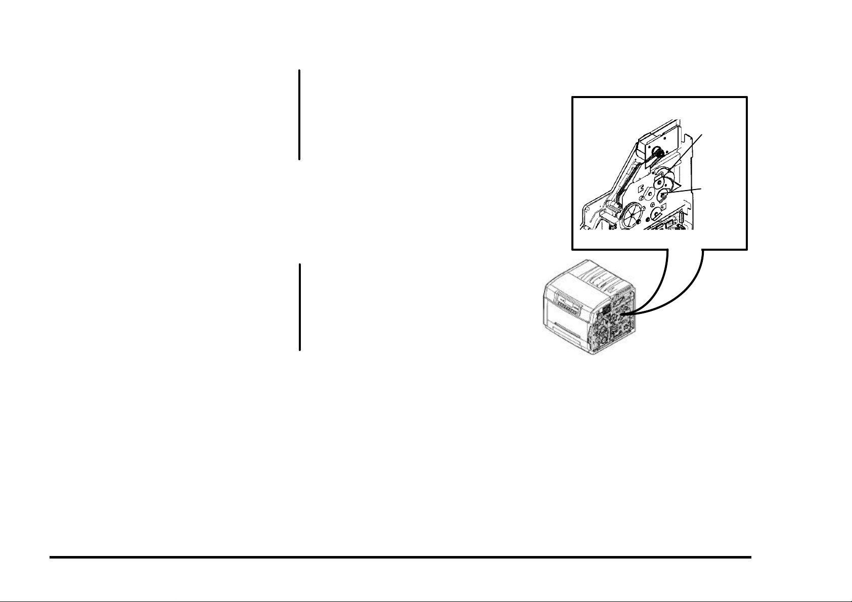
PROCEDURE
Enter IOT normal diagnostics. Scroll to the
MOTOR TEST program and Press Form
Feed [1] to switch on the motors while
observing the Color Toner Motor.
The Color Toner Motor is rotating normally.
A
A
Y N
Refer to BSD 9.11 in Section 7 and
troubleshoot the Color Toner Motor lines
(CN116-1, 2) for an open or a short to
ground.
If no wiring problem exists, replace the
PCU PWB. If the problem still exists,
replace the Color Toner Motor.
Exit from diagnostics.
Set up the meter to read +24 VDC. Measure
between CN115-14 (+) and ground (−).
Switch the power off wait 10 seconds and
switch the power on while monitoring the meter.
The meter swings from +24 VDC to 0.
Y N
Go to BSD 9.10 in Section 7 and trouble-
shoot the Magenta Toner Solenoid signal
and +24 VDC Interlocked (CN115-14, 13)
for an open.
If no open exists, replace the PCU PWB.
If the problem still exists, replace the
Magenta Toner Solenoid.
Check the Magenta Dispense Shaft to see if it
rotates when the Solenoid energizes. If not,
look for a mechanical problem (gears etc.).
Check the ground to the Magenta Toner
Concentration Sensor (CN118-5 to CN1009-
21) BSD 9.10.
If the ground is OK, replace the PCU PWB.
Color
Toner
Motor
M Disp.
Shaft
01/02
STATUS INDICATOR RAPs 2/99
J2 2-16 DocuPrint C55/C55mp/[NC60]
Page 31

J3 ADD CYAN TONER RAP
The cyan toner concentration sensor has
detected low cyan toner in the cyan developer
assembly. When this occurs, the Printer will
display “Adjusting Print Quality” and attempt to
tone up.
NOTE: If a new color developer housing has
been installed, make sure the 3 seals have
been removed from the left side of the
housing.
INITIAL ACTION
Check with the customer to see if they have
already added Cyan Dry Ink. Add Cyan Dry
Ink, if required.
Adding too much toner can cause the toner to
“cake” and not be dispensed.
(C55/C55mp)
Put the printer in the Off Line mode.
Select the SERVICE Menu and print a
Diagnostic Test Sheet.
Determine the Engine Software version from
the Diagnostic Test Sheet. If the Software
level is Version 66, replace the PCU PWB.
All Printers, switch the power off wait 10
seconds and switch the power on. Allow the
Printer to try to tone up to recheck for the fault.
PROCEDURE
Enter IOT normal diagnostics. Scroll to the
MOTOR TEST program and Press Form
Feed [1] to switch on the motors while
observing the Color Toner Motor.
The Color Toner Motor is rotating normally.
A
A
Y N
Refer to BSD 9.11 in Section 7 and
troubleshoot the Color Toner Motor lines
(CN116-1, 2) for an open or a short to
ground.
If no wiring problem exists, replace the
PCU PWB. If the problem still exists,
replace the Color Toner Motor.
Exit from diagnostics.
Set up the meter to read +24 VDC. Measure
between CN115-12 (+) and ground (−).
Switch the power off wait 10 seconds and
switch the power on while monitoring the meter.
The meter swings from +24 VDC to 0.
Y N
Go to BSD 9.10 in Section 7 and trouble-
shoot the Cyan Toner Solenoid signal and
+24 VDC Interlocked (CN115-12, 11) for
an open.
If no open exists, replace the PCU PWB.
If the problem still exists, replace the Cyan
Toner Solenoid.
Check the Cyan Dispense Shaft to see if it
rotates when the Solenoid energizes. If not,
look for a mechanical problem (gears etc.).
Check the ground to the Cyan Toner
Concentration Sensor (CN118-6 to CN1009-
17) BSD 9.10.
If the ground is OK, replace the PCU PWB.
Color
Toner
Motor
C Disp.
Shaft
01/02
2/99 STATUS INDICATOR RAPs
DocuPrint C55/C55mp/[NC60] 2-17 J3
Page 32

J4 ADD BLACK TONER RAP
The black toner concentration sensor has
detected low black toner in the black developer
assembly. When this occurs, the Printer will
dead cycle and attempt to tone up.
NOTE: If a new black developer housing has
been installed, make sure the packing material
has been removed.
INITIAL ACTION
Check with the customer to see if they have
already added Black Dry Ink. Add Black Dry
Ink, if required.
Adding too much toner can cause the toner to
“cake” and not be dispensed.
Check the Black toner hopper to ensure that it
is latched closed and is opening the shutter to
the developer housing.
(C55/C55mp)
Put the printer in the Off Line mode.
Select the SERVICE Menu and print a
Diagnostic Test Sheet.
Determine the Engine Software version from
the Diagnostic Test Sheet. If the Software
level is Version 66, replace the PCU PWB.
All Printers, switch the power off wait 10
seconds and switch the power on. Recheck
for the fault.
PROCEDURE
Remove the Printer Rear Cover. There is a
hole located at the left rear of the printer. This
hole is used to view the gears for the Toner
motor.
NOTE: In the following steps, we will be
operating the Black Toner Motor. Do not allow
the motor to run for over 2 seconds or
overtoning can result.
A
A
Enter IOT normal diagnostics. Scroll to the
MOTOR TEST program and press Form Feed
[1] to switch on the motors. Look through the
hole and switch on the Black Toner Motor by
pressing On Line [0]. Release On Line [0] to
stop the motor. Press Media Server [2] to
stop the test.
The Motor Runs.
Y N
Set up the meter to read +24 VDC.
Measure between CN107-13 (+) and
ground (−). Press Form Feed [1] to
switch on the motors. Press On Line [0]
to switch on the Black Toner Motor.
Release On Line [0] to stop the motor.
Press Media Server [2] to stop the test.
The meter reads approximately 12 VDC
when On Line [0] was pressed.
Y N
Go to BSD 9.8 in Section 7 and
troubleshoot the Black Toner Motor
lines (CN107-13, 14) for an open.
If the lines are OK, replace the Black
Toner Motor
Check the Black toner box for auger
binding.
Check the ground to the Black Toner
Concentration Sensor (CN107-2 to
CN1001-4) BSD 9.7.
If the ground is OK, replace the PCU
PWB.
Toner should be dispensed, check the Black
toner box for auger binding.
Check the ground to the Black Toner
Concentration Sensor (CN107-2 to CN1001-4)
BSD 9.7.
If the ground is OK, replace the PCU PWB.
STATUS INDICATOR RAPs 2/99
J4 2-18 DocuPrint C55/C55mp/[NC60]
Page 33

J5 REPLACE COLOR DEVELOPER
CARTRIDGE RAP
NOTE: This code is normally preceded by a
W1 code.
The Color Developer Cartridge is at end of life.
INITIAL ACTION
Check the Color Developer Cartridge life.
(C55/C55mp)
Press On Line, then press Menu, use Next to
scroll to the MAINTENANCE menu, press
Enter. Use Next to scroll to COLOR DEV
CART, press Enter.
[NC60]
Press Menu Up until Service, Item Down until
CRU Usage. Press Value Up to scroll to the
Color Dev. Cart.
Check the % remaining on the Color
Developer Cartridge. If the cartridge is at end
of life, notify the customer and have them
install a new Color Developer Cartridge.
PROCEDURE
Check the developer drive motor, belts and
gears to ensure that they are rotating.
If the J5 code does not clear when a new Color
Developer Cartridge is install, go to BSD 9.10
and check the New Developer Sense signal
(CN118-7) for an open or short to ground.
If the J5 code exists even though the Color
Cartridge has not reached end of life refer to
BSD 9.10 and check the following:
• Cyan Toner Sense signal for an open or a
short to ground (CN118-10).
• Cyan Toner +5 VDC for an open (CN118-3).
• Magenta Toner Sense signal for an open or
a short to ground (CN118-9).
• Magenta Toner +5 VDC for an open
(CN118-2).
A
A
• Yellow Toner Sense signal for an open or a
short to ground (CN118-8).
• Yellow Toner +5 VDC for an open
(CN118-1).
If all of the above check OK, replace the Color
Developer Cartridge. If the problem still exists,
replace the PCU PWB.
J6 REPLACE BLACK DEVELOPER
CARTRIDGE RAP
NOTE: This code is normally preceded by a
W2 code.
The Black Developer Cartridge is at end of life.
INITIAL ACTION
Check the Black Developer Cartridge life.
(C55/C55mp)
Press On Line, then press Menu, use Next to
scroll to the MAINTENANCE menu, press
Enter. Use Next to scroll to BLACK DEV
CART, press Enter.
[NC60]
Press Menu Up until Service, Item Down until
CRU Usage. Press Value Up to scroll to the
Black Dev. Cart.
Check the % remaining on the Black
Developer Cartridge. If the cartridge is at end
of life, notify the customer and have them
install a new Black Developer Cartridge.
PROCEDURE
If the J6 code does not clear when a new
Black Developer Cartridge is install, go to BSD
9.7 and check the New Developer Sense
signal (CN107-3) for an open or short.
If the J6 code exists even though the Black
Cartridge has not reached end of life refer to
BSD 9.7 and check the following:
• Black Toner Sense signal for an open or a
short to ground (CN107-4).
• Black Toner +5 VDC for an open
(CN107-1).
If all of the above check OK, replace the Black
Developer Cartridge. If the problem still exists,
replace the PCU PWB.
2/99 STATUS INDICATOR RAPs
DocuPrint C55/C55mp/[NC60] 2-19 J5, J6
Page 34

J7 TONER COLLECTOR FULL RAP
The Toner Collector is full or not installed
correctly.
INITIAL ACTION
Remove the Toner Collector and ensure that it
is not full.
Check to ensure that the channel that the
sensor “looks” through is not blocked with
toner.
Reinstall the Toner Collector.
PROCEDURE
Enter IOT normal diagnostics. Scroll to the
SWITCH SCAN program and select Scan Row
02. Press Form Feed [1].
Open the Printer. Remove and reinstall the
Toner Collector while observing the Yellow
LED.
The Yellow LED switches on and off
Y N
Go to BSD 9.21 in Section 7 and troubleshoot the Waste Toner Sensor signal,
+5 VDC, and GND (CN102-3, 1, 2) for an
open.
If no open exists, replace the PCU PWB.
If the problem still, exists replace the
Waste Toner Sensor.
Install a new Toner Collector.
J8 REPLACE PRINT DRUM RAP
The Print Drum is at end of life, is not in place,
or is not installed correctly.
NOTE: This code is normally preceded by a
W3 code.
INITIAL ACTION
Check the Print Drum Cartridge life.
(C55/C55mp)
Press On Line, then press Menu, use Next to
scroll to the MAINTENANCE menu, press
Enter. Use Next to scroll to PRINT DRUM,
press Enter.
[NC60]
Press Menu Up until Service, Item Down until
CRU Usage. Press Value Up to scroll to the
Print Drum.
Check the % remaining on the Print Drum
Cartridge. If the cartridge is at end of life,
notify the customer and have them install a
new Print Drum Cartridge.
PROCEDURE
If the J8 code does not clear when a new Print
Drum Cartridge is installed, go to BSD 9.2 and
check the New Drum Detect signal
(CN107-15) for an open or short to ground.
Also check +5 VDC (CN107-17) for an open.
If the J8 code exists even though the Print
Drum Cartridge has not reached end of life,
refer to BSD 9.2 and check the Drum Detect
signal (CN107-19).
If all of the above check OK, replace the Print
Drum Cartridge. If the problem still exists,
replace the PCU PWB.
J9 REPLACE FUSER MODULE RAP
The Fuser is at end of life.
NOTE: This code is normally preceded by a
W4 code.
INITIAL ACTION
Check the Fuser Cartridge life.
(C55/C55mp)
Press On Line, then press Menu, use Next to
scroll to the MAINTENANCE menu, press
Enter. Use Next to scroll to FUSER
MODULE, press Enter.
[NC60]
Press Menu Up until Service, Item Down until
CRU Usage. Press Value Up to scroll to the
Fuser Module.
Check the % remaining on the Fuser Module.
If the module is at end of life, notify the
customer and install a new Fuser Module.
PROCEDURE
If the J9 code does not clear when a new
Fuser Module is install, go to BSD 10.5 and
check the New Fuser Detect signal (CN103-8,
CN306-4) for an open or short to ground. Also
check +5 VDC (CN306-1) for an open.
If all of the above check OK, replace the Fuser
Module. If the problem still exists, replace the
PCU PWB.
STATUS INDICATOR RAPs 2/99
J7, J8, J9 2-20 DocuPrint C55/C55mp/[NC60]
Page 35

JA REPLACE OIL/PAD RAP
The Oil/Pad needs to be replaced.
INITIAL ACTION
Check the Oil Bottle and sump. If required,
replace the Wiper Roll and Oil Bottle. If this
code persists after a new Oil Bottle is installed
or the Oil is OK, continue with this RAP.
Paper dust and other contaminants can cause
the fuser oil to get cloudy and solidify causing
the ball that triggers the Low Oil Sensor to
stick. When low oil is detected, the printer will
stop and the fuser will be powered off after 50
prints to prevent Fuser damage. If the fuser
has the contamination described above, the
ball could be stuck in a position that will
prevent the fuser from warming up.
Check to ensure the fuser sump has oil in it.
There have been some reported instances of
defective oil bottles failing to dispense oil into
the sump.
Ensure that the valve stem on the oil bottle is
not bent or off center. A bent stem will not
engage the plunger in the sump correctly.
If the sump is full, check to see if the ball is
stuck in the bottom of the channel. If it is, you
may be able to correct the problem by
removing the rubber stopper in the tank above
the ball and using a scribe or screwdriver to
loosen the ball.
NOTE: This is only a temporary fix. You
should have the customer order a new fuser
assembly. If in your judgment this is a
premature failure, follow the applicable
warranty replacement procedures.
If the problem still exists continue with this
RAP.
PROCEDURE
Enter IOT normal diagnostics. Scroll to the
SWITCH SCAN program and select Scan Row
05. Press Form Feed [1].
Open the Printer and remove the Fuser
Assembly.
Actuate and deactuate the Oil Sensor while
observing the Cyan LED.
The Cyan, LED switches off and on.
Y N
With Scan Row 05 still selected, actuate
and deactuate the Cleaner Jam Switch
while observing the Magenta LED.
The Magenta, LED switches off and on.
Y N
Refer to BSD 10.4 and check the
Strobe 1 signal CN103-19 for an open.
If no open exists replace the PCU
PWB.
Refer to BSD 10.4 and check the Oil Low
signal, +5 VDC and GND CN309-2, 1, 3
for an open.
If no open exists, replace the PCU PWB.
If the problem still exists, replace the Oil
Sensor.
Check the ball that actuates the Oil Sensor to
ensure that it is moving freely. Reinstall the
Fuser Assembly and close the printer to see if
the fault clears.
If the problem still exists replace the Wiper
Roll and Oil Bottle. If the problem still exists,
replace the PCU PWB.
T0 THERMISTOR ERROR RAP
The Fuser Thermistor readings are out of
range, the Fuser is missing, or the Fuser is not
seated correctly.
INITIAL ACTION
NOTE: During the following check be careful
not to tip the Fuser.
Remove the Fuser Module and check the
condition of the Fuser Connectors.
Check the operation of the shutter that covers
the fuser connectors.
Reinstall the Fuser Module.
Switch the power off wait 10 seconds and
switch the power on. Recheck for the fault.
PROCEDURE
Set up the meter to read +5 VDC. Measure
between CN103-9 (+) and ground (−).
When the fuser is cold, the reading should be
around 0.1 VDC. When the fuse is hot, the
reading should be approximately 3.5 VDC.
The readings are OK.
Y N
Go to BSD 10.5 in Section 7 and troubleshoot the Fuser Thermistor signal and
+5 VDC for an open or a short to ground
(CN103-9, CN306-3, 2).
If the wiring is OK, replace the Fuser
Assembly. If the problem still exists,
replace the PCU PWB.
Replace the PCU PWB.
2/99 STATUS INDICATOR RAPs
DocuPrint C55/C55mp/[NC60] 2-21 JA, T0
Page 36

T1 UNDER TEMPERATURE RAP
NOTE: This RAP applies to both 115 and 220
volt printers. The 220 volt readings will be in
parenthesis.
After the proper warm up time has elapsed,
the fuser temperature is less than 85°C.
INITIAL ACTION
Remove the Fuser Module and check the
condition of the Fuser Connectors. Also check
to ensure that the ball which actuates the Low
Oil Sensor is moving freely. The ball could be
stuck in the down position which will prevent
the fuser from warming up. If the ball is not
free, you may be able to correct the problem
by removing the rubber stopper in the tank
above the ball and using a scribe or
screwdriver to loosen the ball.
NOTE: This is only a temporary fix. You
should have the customer order a new fuser
assembly. If in your judgment this is a
premature failure, follow the applicable
warranty replacement procedures.
Switch the power off wait 10 seconds and
switch the power on. Recheck for the fault.
PROCEDURE
Switch the power off.
Locate connector CN1004/CN1008. This is a
two-wire (black and white wires, heavy gauge)
connector that provides AC power to the fuser.
The connector is located just to the left of the
PCU board (as you are looking at it).
Disconnect CN1004/CN1008.
Set up the meter to read Ohms. Connect the
meter between pins 1 & 2 of CN1008 the
Fuser side, (left connector) and measure the
resistance.
The resistance is less than 10 Ohms.
Y N
A B
A B
Go to BSD 10.5 in Section 7 and troubleshoot the Fuser connectors (CN1008,
1009) for an open circuit. If the wiring is
OK, replace the Fuser Module.
CAUTION
Be careful during the following test, High
Voltage AC may be present.
Set up the meter to measure 120 (220) VAC.
Connect between CN1004-2 and CN1004-1,
the LVPS side, (right connector).
Switch the Power on.
The reading is approximately 115 (220)
VAC.
Y N
Switch the printer off. Reconnect
CN1004/CN1008.
Set up the meter to read +24 VDC.
Measure between CN107-20 (+) and
ground (−).
Switch the printer on.
Open and close the Printer while
observing the meter.
The meter reads 24 VDC with the Printer
open and 0 VDC with the Printer closed.
Y N
Go to BSD 10.5 and troubleshoot the
AC on (L) signal and +24 VDC Interlocked (CN107-20, 16) for an open.
If the wiring is OK, replace the PCU
PWB. If the problem still exists,
replace the Low Voltage Power
Supply.
C D
C D
Measure between CN107-18 (+) and
ground (−).
The meter reads 0 VDC while the fuser
is trying to warm up.
Y N
Go to BSD 10.5 and troubleshoot the
Fuser on (L) signal (CN107-18) for an
open.
If the wiring is OK, replace the PCU
PWB. If the problem still exists,
replace the Low Voltage Power
Supply.
Measure between CN107-22 (+) and
ground (−).
The meter reads 0 VDC while the fuser
is trying to warm up.
Y N
Go to BSD 10.5 and troubleshoot the
Heat Rod Sense (L) signal (CN107-
22) for a short to ground.
If the wiring is OK, replace the PCU
PWB. If the problem still exists,
replace the Low Voltage Power
Supply.
Replace the Low voltage power supply.
Go to BSD 10.5 in Section 7 and troubleshoot
the Fuser connectors (CN1004, 1008, 1009)
for an open circuit. If OK, replace the Fuser
Module.
STATUS INDICATOR RAPs 2/99
T1 2-22 DocuPrint C55/C55mp/[NC60]
Page 37

T2 OVER TEMPERATURE RAP
The fuser temperature is greater than 240°C.
INITIAL ACTION
Remove the Fuser Module and check the
condition of the Fuser Connectors. Reinstall
the Fuser Module.
Switch the power off wait 10 seconds and
switch the power on. Recheck for the fault.
PROCEDURE
Allow the fuser to cool. Set up the meter to
read +24 VDC. Measure between CN107-18
(+) and ground (−).
When the fuser is cold, the reading should be
around 0 VDC. When the fuse warms up, the
reading should switch to approximately 22
VDC.
The readings are OK.
Y N
Go to BSD 10.5 in Section 7 and troubleshoot the Fuser on (L) signal for a short to
ground CN107-18).
If the wiring is OK, replace the PCU PWB.
If the problem still exists, replace the Low
Voltage Power Supply.
Triac shorted, replace the Low Voltage Power
Supply.
U0 IOT ROM ERROR RAP
A ROM error was detected.
INITIAL ACTION
Switch the power off wait 10 seconds and
switch the power on. Recheck for the fault.
If the problem still exists, replace the PCU
PWB.
2/99 STATUS INDICATOR RAPs
DocuPrint C55/C55mp/[NC60] 2-23 T2, U0
Page 38

U1 IOT RAM ERROR RAP
A RAM error was detected.
INITIAL ACTION
Switch the power off wait 10 seconds and
switch the power on. Recheck for the fault.
If the problem still exists, replace the PCU
PWB.
U2 IOT NVM RAM ERROR RAP
A NVM error was detected.
Many xerographic parameters and other
values are written to the NVM on the PCU
PWB every time the machine is powered off.
These values can be corrupted when the
printer is powered off and on too quickly, or
when there is an irregularity in the power to the
printer. This can produce a U2 error code.
If the NVM is initialized without following the
proper procedures the toner concentration
setpoints will not match those for the
developer housings in the printer. The printer
will then attempt to adjust the toner
concentration to values that may be out of
range for the housings. The can result in
incorrect toner concentration values, or the
machine may hang-up with the “Adjusting Print
Quality” message.
When taking a U2 service call, you must
carefully follow the steps in ADJ 3.3 and
determine the current Toner Concentration
Setpoints before you actual “Initialize the
NVM”.
INITIAL ACTION
Switch the power off wait 10 seconds and
switch the power on. Recheck for the U2 fault.
If the problem still exists, refer to ADJ 3.3 NVM
Initialization (U2) in section 4.
U3 IOT/ESS COMMUNICATION
ERROR RAP
A communication error between the ESS and
the IOT was detected.
INITIAL ACTION
Switch the power off wait 10 seconds and
switch the power on. Recheck for the fault.
If the problem still exists, replace the PCU
PWB.
If the problem still exists, replace the ESS
PWB.
STATUS INDICATOR RAPs 2/99
U1, U2, U3 2-24 DocuPrint C55/C55mp/[NC60]
Page 39

U4 OPTICS FAULT
A ROS problem was detected. The laser did
not come on.
INITIAL ACTION
Switch the power off wait 10 seconds and
switch the power on. Recheck for the fault.
Check to ensure that the printer covers are
closed. Inspect the Laser Interlock (smaller of
the two switches) to ensure that it is actuated.
PROCEDURE
Locate connector 1007. This is a small DC,
two wire connector located above and to the
right of the PCU PWB.
Set up the meter to read +5 VDC. Connect
the meter to CN1007-2 (+) (this pin goes to the
ROS assembly harness) and ground (−).
Open and close the Printer while monitoring
the meter.
The meter reads 0 VDC when the Printer is
open and switches to +5 VDC when the
Printer is closed.
Y N
Go to BSD 6 in Section 7 and troubleshoot
the Laser Interlock Switch circuit (CN113-
12) for an open.
A
• (CN113-11) GND.
• (CN113-10) SYNC.
• (CN113-8) VIDEO DATA.
• (CN113-7) LASER DIODE ON (L) +5 VDC.
If the wiring appears OK, replace the PCU
PWB.
If the problem still exists, replace the ROS.
U5 POLYGON MOTOR FAULT
A ROS problem was detected. The Polygon
Motor did not come up to the proper speed.
INITIAL ACTION
Switch the power off wait 10 seconds and
switch the power on. Recheck for the fault.
PROCEDURE
Go to BSD 6 in Section 7 Connector CN113
and check the following pins for a good
connection:
• (CN113-5) LASER LOCK.
• (CN113-4) POLYGON MOTOR LOCK (L)
+5 VDC.
• (CN113-3) POLYGON MOTOR ON (L)
+5 VDC.
• (CN113-2) GND.
• (CN113-1) +24 VDC INTERLOCKED.
If the wiring appears OK, replace the PCU
PWB.
If the problem still exists, replace the ROS.
If no open exists, replace the PCU PWB.
If the problem still exists, replace the
Laser Interlock Switch
Go to BSD 6 in Section 7 Connector CN113
and check the following pins for a good
connection:
A
2/99 STATUS INDICATOR RAPs
DocuPrint C55/C55mp/[NC60] 2-25 U4, U5
Page 40

U6 MOTOR FAULT (DEVELOPER)
RAP
The Developer Drive motor is not running.
NOTE: This problem can be caused by arcing
at the Print Drum Module spring contacts. If
the U6 code is intermittent and occasionally
accompanied by a high pitch squeal, clean and
reform the spring contacts. It the problem
persists replace the Print Drum Module.
INITIAL ACTION.
Remove and inspect both developer modules.
Check to ensure no foreign material is wedged
in the drive gears and the gears on both
modules rotate freely.
Reinstall both developer modules.
Check the Toner Collector for “layered” toner
(sand-art effect). If layered toner is present,
refer to OF8 Arcing RAP.
Switch the power off wait 10 seconds and
switch the power on. Recheck for the fault.
PROCEDURE
Set up the meter to read +5 VDC. Connect
the meter to CN117-2 and ground (−).
Enter IOT normal diagnostics. Scroll to the
MOTOR TEST program and press Form Feed
[1] to switch on the motors while observing the
meter.
The meter reads + 5 VDC before the motor
program starts and 0 VDC when the motor
program is running.
Y N
Set up the meter to read +24 VDC.
Connect the meter to CN117-3 and ground
(−).
A B
A B
The meter reads + 24 VDC.
Y N
Go to BSD 9.5 in Section 7 and
troubleshoot the +24 VDC (CN117-3)
for an open.
If no open exists, replace the PCU
PWB.
Go to BSD 9.5 in Section 7 and troubleshoot the Developer Motor On signal
(CN117-2) for an open.
If no open exists, replace the PCU PWB.
If the problem still exists, replace the
Developer Drive Motor.
Press Media Server [2] to stop the MOTOR
TEST program.
Set up the meter to read +5 VDC. Connect
the meter to CN117-1 and ground (−).
Press Form Feed [1] to switch on the motors
while observing the meter.
The meter reads + 5 VDC before the motor
program starts and 0 VDC when the motor
program is running.
Y N
Go to BSD 9.5 in Section 7 and troubleshoot the Developer Motor Lock signal
(CN117-1) for an open.
If no open exists, replace the PCU PWB.
If the problem still exists, replace the
Developer Drive Motor.
Go to BSD 9.5 in Section 7 and troubleshoot
the GND (CN117-4) for an open.
If OK, replace the PCU PWB. If the problem
still exists, replace the Developer Drive Motor.
STATUS INDICATOR RAPs 2/99
U6 2-26 DocuPrint C55/C55mp/[NC60]
Page 41

U7 MOTOR FAULT (MAIN) RAP
The Transfer Drum Home Position Sensor did
not detect Transfer Drum rotation.
(C55/C55mp)
Mechanical bind is the most common cause
of this fault, specifically binding of the auger
in the Print Drum. This is usually (but not
always) accompanied by a clicking noise
from the top of the machine.
If a clicking noise is heard, enter “Normal
Diagnostics” (General Procedures) and
attempt to run the Motor Test. Note the
sounds of the machine. Stop the test,
remove the print drum, close the printer, and
run the Motor Test again. Note any
changes in the sounds. If there is a
noticeable change in the sound, examine the
Print Drum by opening the Waste Toner trap
door and probing with a small screwdriver. If
this area is clogged, you can remove the left
side cover by removing the trap door and
removing 4 screws. This area can then be
vacuumed out before reassembly.
All Printers, if a thumping noise is heard,
check to see if the Main Drive Motor Belt is
slipping.
INITIAL ACTION
Remove and inspect the Print Drum Module.
Check to ensure that no foreign material is
wedged in the Print Drum Module drive gears.
Rotate the Transfer Drum by hand to ensure
that it moves. Check for any binding caused
by a tucked over Transfer Drum Cleaner Brush
Blade
Reinstall the Print Drum Module.
Switch the power off wait 10 seconds and
switch the power on. Recheck for the fault.
PROCEDURE
Enter IOT normal diagnostics. Scroll to the
MOTOR TEST program and press Form Feed
[1] to switch on the motors while observing the
Main Drive Motor.
The Main Drive Motor is rotating.
Y N
The Main Motor is noisy.
Y N
Go to BSD 9.3 in Section 7 and
troubleshoot the +24 VDC Interlocked
(CN112-5).
If OK, replace the PCU PWB. If the
problem still exists, replace the Main
Drive Motor.
Go to BSD 9.3 in Section 7 and check
(CN112) to ensure it is plugged in.
If the problem still exists replace the PCU
PWB. If the problem still exists, replace
the Main Drive Motor.
Press Media Server [2] to stop the MOTOR
TEST program.
Scroll to the SWITCH SCAN program and
select Scan Row 04. Press Form Feed [1].
Open the Printer. Slowly rotate the Transfer
Drum while observing the Magenta LED.
The Magenta LED switches on and off.
Y N
A B
A B
Go to BSD 9.13 in Section 7 and troubleshoot the Transfer Drum Home Position
signal, +5 VDC, and ground (CN103-17,
CN313-2, 1, 3) for an open or a short to
ground.
If the wiring is OK, replace the PCU PWB.
If the Problem still exists replace the
Transfer Drum Home Position Sensor.
Replace the PCU PWB.
2/99 STATUS INDICATOR RAPs
DocuPrint C55/C55mp/[NC60] 2-27 U7
Page 42

W1 COLOR DEV MOD RAP
This code indicates that the Color Developer
module is near the end of life (10% remaining).
When a J5 occurs the customer should install
a new Color Developer Module.
When the new Color Developer Module is
installed, the J5 and W1 codes will no longer
appear.
If the J5 code still exists, refer to the J5 RAP
W2 BLACK DEV MOD RAP
This code indicates that the Black Developer
module is near the end of life (10% remaining).
When a J6 occurs the customer should install
a new Black Developer Module.
When a new Black Developer Module is
installed, the J6 and W2 codes will no longer
appear.
If the J6 code still exists, refer to the J6 RAP
W3 PRINT DRUM MOD RAP
This code indicates that the Photoreceptor
module is near the end of life (10% remaining).
When a J8 occurs the customer should install
a new Print Drum Module.
When a new Print Drum Module is installed,
the J8 and W3 codes will no longer appear.
If the J8 code still exists, refer to the J8 RAP
STATUS INDICATOR RAPs 2/99
W1, W2, W3 2-28 DocuPrint C55/C55mp/[NC60]
Page 43

W4 FUSER MOD RAP
This code indicates that the Fuser module is
near the end of life (10% remaining).
When a J9 occurs the customer should install
a new Fuser Module.
When the new Fuser Module is installed, the
J9 and W4 codes will no longer appear.
If the J9 code still exists, refer to the J9 RAP
W5 FUSER OIL BOTTLE/PAD RAP
This code indicates that the Oil Bottle and Pad
are near the end of use.
When a JA occurs the customer should install
a new Fuser Oil Bottle and Pad.
When a new Oil Bottle is installed, the JA and
W5 codes should no longer appear.
If the JA code still exists, refer to the JA RAP
2/99 STATUS INDICATOR RAPs
DocuPrint C55/C55mp/[NC60] 2-29 W4, W5
Page 44

OF1 DEAD PRINTER RAP
This RAP is used when the Printer is dead.
There is no display, no Control Panel LEDs
are on, and no motors or fans are heard when
the printer is switched on.
NOTE: A description of the C55 and NC60
IOT and ESS boot routines can be found in
Section 6 of this manual. Refer to the Section
6 Table of Contents.
INITIAL ACTION
Remove the power cord and check for AC
power at the wall outlet. If there is no power at
the wall outlet, ask the customer to call an
electrician to restore the AC power.
If power is available at the wall outlet,
disconnect the power cord from the printer.
Plug the cord into the wall and check for AC
power at the printer end of the power cord. If
power is available at the wall outlet but not
available at the printer end, replace the power
cord.
PROCEDURE
WARNING
Disconnect all network, and workstation
inputs to the printer.
A
A
Switch the printer off wait 10 seconds and
switch the printer on while listening to the IOT
and observing the Message Display.
The IOT runs when the printer is switched
on.
Y N
Set up the meter to measure +5 VDC.
Measure between CN108-1 (+) and
CN108-2 (−).
The meter indicates +5 VDC.
Y N
Go to OF1.1 + 5 VDC RAP
Set up the meter to measure +5 VDC.
Measure between CN310-11 (+) and
CN310-10 (−).
The meter indicates +5 VDC.
Y N
Replace the Connector PWB.
Go to OF2 CONTROL PANEL RAP.
Switch the printer off wait 10 seconds and
switch the power on while observing the LEDs
on the ESS PWB.
The ESS appears to boot normally and the
Control Panel is blank.
Y N
Check CN104, the ESS to IOT connector.
If OK, go to OF6A (C55/C55mp) or OF6B
[NC60].
Go to OF2 CONTROL PANEL RAP
OTHER FAULTS RAP’s 2/99
OF1 2-30 DocuPrint C55/C55mp/[NC60]
Page 45

OF1.1+5 VDC RAP
This RAP is used when the +5 VDC is not
present at the PCU PWB. The printer is dead,
the display and LEDs are off. No motors or
fans are heard when the printer is switched on.
INITIAL ACTION
Switch the Printer off.
WARNING
Disconnect all network, and workstation
inputs to the printer.
PROCEDURE
Loosen the two thumb screws on the rear of
the ESS and slide the ESS about half-way out
of the printer. Switch the printer on.
The printer is still dead, the display and
LEDs are off. No motors or fans are heard
when the printer is switched on.
Y N
The printer booted when it was switched
on. The display is now a circling asterisk.
Switch the printer off. If the printer does
NOT have a NIC, replace the ESS.
If the printer does have a NIC, slide the
ESS back into the printer and remove the
NIC. Switch the Printer on.
The Printer is still dead, the display and
LEDs are off. No motors or fans are heard
when the printer is switched on.
Y N
The printer booted when it was
switched on. The display is now a
circling asterisk.
Replace the NIC
A B
A B
Replace the ESS.
Switch the printer off. Disconnect CN104 from
the ESS Interface PWB. Switch the printer on.
The printer is still dead, the display and
LEDs are off. No motors or fans are heard
when the printer is switched on.
Y N
The printer booted when it was switched
on. The display is now a circling asterisk.
Switch the printer off. Reconnect CN104.
Disconnect CN102 and CN103 from the
Floppy Drive. Switch the printer on.
The printer is still dead, the display and
LEDs are off. No motors or fans are
heard when the printer is switched on.
Y N
The printer booted when it was
switched on. The display is now a
circling asterisk.
Replace the Floppy Drive.
If the printer does NOT have a hard drive,
replace the ESS Interface PWB.
If the printer has a Hard Drive, switch the
printer off. Reconnect CN102 and CN103.
Disconnect CN101 from the Hard Drive.
Switch the printer on.
The printer is still dead, the display and
LEDs are off. No motors or fans are
heard when the printer is switched on.
Y N
C D E
C D E
The printer booted when it was
switched on. The display is now a
circling asterisk.
Replace the Hard Drive.
Replace the ESS PWB.
Switch the printer off. Disconnect CN108 from
the PCU PWB.
Connect the meter between CN108-1 (+) and
CN108-2 (−). The meter should be connected
to the connector side NOT the PWB side.
Switch the printer on.
The meter indicates +5 VDC.
Y N
Refer to BSD 1.2 and Check CN108 to
CN707 for an open.
If no open is found, remove the Low
Voltage Power Supply (REP. 3.1).
Remove Fuses F701, F702, and F703.
Use the Ohmmeter to check these fuses.
If any of the fuses test bad, install a new
fuse reassemble the printer and recheck.
If all fuses check OK, replace the Low
Voltage Power Supply.
Replace the PCU PWB. If the problem still
exists replace the Connector PWB.
2/99 OTHER FAULTS RAPs
DocuPrint C55/C55mp/[NC60] 2-31 OF1
Page 46

OF2 CONTROL PANEL RAP
This RAP is used when the Control Panel
Message Display, LEDs, or Buttons do not
work.
INITIAL ACTION
Switch the power off wait 10 seconds and
switch the power on and recheck for the fault.
Enter IOT normal diagnostics (Menu [3],
Enter [7] + Power On) and check the
operation of the Control Panel. If the Control
Panel works OK in diagnostics, refer to BSD 6
and check the PCU to ESS connectors
CN104. If the connections are OK, replace the
ESS PWB.
PROCEDURE
Classify the problem into one of the following
categories, then go to the appropriate
subsection of the RAP.
OF2.1 The Message Display top row consists
of n‘s. The bottom row is blank.
OF2.2 The Message Display is blank (no *
during IOT Boot).
OF2.3 The message display is flickering off
and on, or displaying random
characters.
OF2.4 Message display works OK, LEDs do
not work correctly.
OF2.5 Message display works OK, Switches
do not work correctly.
OF2.6 * Circles Continuously.
OF2.7 Rebooting message never clears.
OF2.1 The Message Display top row
consists of n‘s. The bottom row is
blank.
PROCEDURE
Switch the power off wait 10 seconds and
switch the power on, while listening to the IOT.
The IOT runs (boots up) when the printer is
switched on.
Y N
Refer to BSD 6 and check the RES signal
(CN104-8) for a short to ground.
Refer to BSD 2.1 and check the D3 signal
(CN103-25) for a short to ground.
It the wiring is OK, replace the PCU PWB.
If the problem still exists, replace the
Control Panel PWB.
Refer to BSD 2.1 and check the following
signals:
• CN103-22 Read/Write for an open.
• CN103-23 Register Select for an open or a
short to ground.
• CN103-24 Display Enable for an open or a
short to ground.
• CN103-25 Data 3 for an open.
• CN103-26 Data 2 for an open.
• Refer to BSD 10.2 and check CN103-18
Strobe 2 for a short to ground.
• Refer to BSD 10.4 and check CN103-19
Strobe 1 for a short to ground.
If all appear OK, replace the Control Panel PWB.
If the problem still exists, replace the PCU PWB.
OF2.2 The Message Display is blank (no *
during IOT Boot).
PROCEDURE
Switch the power off wait 10 seconds and
switch the power on, while listening to the IOT.
The IOT runs (boots up) when the printer is
switched on.
Y N
Set up the meter to measure +5 VDC.
Measure between CN310-10 (+) and
CN310-11 (−).
The meter indicates +5 VDC.
Y N
Go to OF1.1 +5 VDC RAP.
Refer to BSD 2.1 and check the +5 VDC
CN310-11 and DC COM CN310-10 from
the Connector PWB to the Control Panel.
If OK, replace the Control Panel PWB.
Refer to BSD 2.1 and check the following
signals:
• CN103-22 Read/Write for a short to
ground.
• CN103-26 Data 2 for a short to ground.
• CN103-27 Data 1 for an open.
• CN103-28 Data 0 for an open.
Refer to BSD 6 and check the following
signals:
• CN104-1 STS (Status) for an open or a
short to ground.
• CN104-5 SRDY (Status Ready) for an
open.
If all appear OK, replace the Control Panel PWB.
If the problem still exists, replace the PCU PWB.
OTHER FAULTS RAPs 2/99
OF2 2-32 DocuPrint C55/C55mp/[NC60]
Page 47

OF2.3 The message display is flickering
off and on, or displaying random
characters.
PROCEDURE
Refer to BSD 2.1 and check the following
signals:
• If the Message is flickering off and on,
check CN103-27 (DATA 1) for an open.
• If the Message is illegible, and the K LED is
on all the time, check CN103-25 (DATA 3)
for a short to ground.
• If the Message is illegible, and the M LED
is on all the time, check CN103-27
(DATA 1) for a short to ground.
• If the Message is illegible, and the Y LED is
on all the time, check CN103-28 (DATA 0)
for a short to ground.
If all appear OK, replace the Control Panel
PWB,
If the problem still exists, replace the PCU
PWB.
OF2.4 Message display works OK, LEDs
do not work correctly.
PROCEDURE
If the On Line LED never comes on, refer to
BSD 6 and check the following:
• CN104-6 CRDY (Command Ready) for an
open.
• CN104-2 CMD (Command) for an open or
a short.
If the LEDs are flickering off and on, refer to
BSD 2.1 and check the following:
• CN103-21 LED Enable for a short to
ground.
If the LEDs are off, refer to BSD 2.1 and check
the following:
• CN103-21 LED Enable for an open.
If all appear OK, replace the Control Panel
PWB.
If the problem still exists, replace the PCU
PWB.
OF2.5 Message display works OK,
Switches do not work correctly.
PROCEDURE
When the switches do not work properly, refer
to BSD 2.1 and check the following:
• CN103-20 Switch Enable for an open or a
short.
If OK, replace the Control Panel PWB.
If the problem still exists, replace the PCU
PWB.
2/99 OTHER FAULTS RAPs
DocuPrint C55/C55mp/[NC60] 2-33 OF2
Page 48

OF2.6 * Circles Continuously.
PROCEDURE
When the * is circling continuously, it is not
receiving messages from the ESS PWB.
Perform the following checks. Retry between
each check.
1. Remove and reseat the ESS PWB. (you
may want to remove the left side cover
and the EME shield to ensure that the
PWB is seated.
2. Disconnect the NIC, if one is present.
3. Remove and reseat the DRAM SIMM’s on
the ESS.
(C55/C55mp) If there are more than two
SIMM’s check to ensure that the larger
value SIMM’s are installed in J8 and J9
4. (C55/C55mp) Check the version of the
ESS PWB. The number is written in
yellow ink, parallel to the ESS face plate
near the bottom of the ESS. The bottom
of the ESS is the point FURTHEST away
from the DRAM SIMM’s. If the ESS PWB
number is 160K43690 or 160K49680
Replace the ESS PWB.
6. (C55/C55mp) If the ESS IF PWB (PL 3.1
#6, 160K32850) has been replaced, check
to see that it has a plastic insulating
washer at each mounting hole. Some of
the spare 160K32850 were manufactured
without these washers. (A purge is under
way to fix this problem. In the meantime,
contact your Technical Support
Organization)
7. Check CN104 harness (between PCU
PWB and IF PWB).
8. Replace PCU PWB.
9. Replace ESS IF PWB (160K32850).
OF2.7 Rebooting message never clears.
When the Rebooting message is displayed the
ESS is booting and waiting for a ready
message from the IOT. The rebooting
message usually lasts for approximately
1 minute and is followed by the Initializing
message.
PROCEDURE
Switch the power off wait 10 seconds and
switch the power on and recheck for the fault.
1. Switch the power off and unplug the ESS
by sliding it out about 6 inches.
2. Run the IOT Test Print.
a. Hold Menu [3] and Enter [7] and
switch the power on.
b. User Menu [3] to scroll to Test Print.
c. Press Form Feed [1].
4. If you cannot enter diagnostics or the test
print does not run, replace the PCU PWB.
5. If the Test Print is produced, replace the
ESS PWB.
5. (C55/C55mp) Reconfigure the ESS PWB
to the original RAM configuration (2-8 MB
SIMM’s) this will verify if this is a DRAM
problem. If the printer works in the original
configuration but not with customers
memory, replace the ESS PWB.
OTHER FAULTS RAPs 2/99
OF2 2-34 DocuPrint C55/C55mp/[NC60]
Page 49

OF3 TRAY 1 PAPER SIZE SENSING
RAP
This RAP is used to troubleshoot the paper
size sensing for Tray 1. Use this RAP when
the paper size that is loaded is not the same
size that is being sensed.
INITIAL ACTION
Remove Tray 1 and check the movable length
stop. Make sure the tab which actuates the
sensors is not broken.
Carefully load the paper size which is not
being detected correctly.
Switch the power off wait 10 seconds and
switch the power on. Make a print of the paper
size which is loaded to recheck for the fault.
PROCEDURE
Enter IOT normal diagnostics. Scroll to the
SWITCH SCAN program and select Scan Row
01. Press Form Feed [1].
Remove Cassette 1. Observe the LED’s.
The Cyan, Magenta and Yellow LEDs are all
off.
Y N
Refer to BSD 7.2 and check the following:
• If all three LEDs are on, check the
+5 VDC, CN107-7 for an open.
• Cyan LED on, check Paper size 0,
CN107-8 for an open.
• Magenta LED on, check Paper Size 1,
CN107-9 for an open.
• Yellow LED on, check Paper Size 2,
CN107-10 for an open.
If wiring is OK, replace the PCU PWB. If
the problem still exists, replace the
Cassette PWB.
A
A
Press Media Server [2], select Scan Row 02.
Press Form Feed [1]. Observe the LED’s.
The Black and Cyan LEDs are off.
Y N
Refer to BSD 7.2 and check the following:
• Black LED on, check Paper size 3,
CN107-11 for an open.
• Cyan LED on, check Paper Size 4,
CN107-12 for an open.
If wiring is OK, replace the PCU PWB. If
the problem still exists, replace the
Cassette PWB.
With Scan Row 02 still selected move the
length stop to the Legal (14") position (Figure
2-3).
Insert the cassette. Observe the LED’s.
The Cyan LED goes on when the cassette
is inserted.
Y N
Refer To BSD 7.2 and check Paper Size
4, CN107-12 for a short to ground.
If wiring is OK, replace the PCU PWB. If
the problem still exists, replace the
Cassette PWB.
Remove the cassette and move the length
stop to the A4 (11.7”)"position.
Insert the cassette. Observe the LED’s.
The Black LED goes on when the cassette is
inserted.
Y N
Refer To BSD 7.2 and check Paper Size
3, CN107-11 for a short to ground.
B C
B C
If wiring is OK, replace the PCU PWB. If
the problem still exists, replace the
Cassette PWB.
Press Media Server [2], select Scan Row 01.
Press Form Feed [1].
Remove the cassette and move the length
stop to the Letter (11”)"position.
Insert the cassette. Observe the LED’s.
The Yellow LED goes on when the cassette
is inserted.
Y N
Refer To BSD 7.2 and check Paper Size
2, CN107-10 for a short to ground.
If wiring is OK, replace the PCU PWB. If
the problem still exists, replace the
Cassette PWB.
Remove the cassette and move the length
stop to the Executive (10.5”)"position.
Insert the cassette. Observe the LED’s.
The Magenta LED goes on when the
cassette is inserted.
Y N
Refer To BSD 7.2 and check Paper Size
1, CN107-9 for a short to ground.
If wiring is OK, replace the PCU PWB. If
the problem still exists, replace the
Cassette PWB.
Replace the PCU PWB. If the problem still
exists, replace the ESS PWB.
14"10.5" 11", A4
Figure 2-3 Length Stop Location
2/99 OTHER FAULTS RAPs
DocuPrint C55/C55mp/[NC60] 2-35 OF3
Page 50

OF4 TRAY 2 PAPER SIZE SENSING
RAP
This RAP is used to troubleshoot the paper
size sensing for Tray 2. Use this RAP when
the paper size that is loaded is not the same
size that is being sensed.
INITIAL ACTION
Remove Tray 2 and check the movable length
stop. Make sure the tab which actuates the
sensors is not broken.
Carefully load the paper size which is not
being detected correctly.
Switch the power off wait 10 seconds and
switch the power on. Make a print of the paper
size which is loaded to recheck for the fault.
PROCEDURE
Enter IOT normal diagnostics. Scroll to the
SWITCH SCAN program and select Scan Row
03. Press Form Feed [1].
Remove Cassette 2. Remove the Length Stop
and re-insert Cassette 2 without the stop.
Observe the LEDs.
Cyan, Magenta, and Yellow are all On.
Y N
Refer to BSD T2 7.2 and check the
following:
• Cyan is Off. Check the T2 Paper Size
0 signal, CN109-1 for a short to
ground.
• Magenta is Off. Check the T2 Paper
Size 1 signal, CN109-2 for a short to
ground.
• Yellow is Off. Check the T2 Paper
Size 2 signal, CN109-3 for a short to
ground.
A B
A B
If OK, replace the T2 Cassette PWB. If
problem still exists, replace the PCU PWB.
With Scan Row 03 still selected remove the
cassette and put the Length Stop in the
Executive (10.5") position (Figure 2-4).
Insert the cassette and observe the LEDs.
Cyan is On, Magenta is Off, and Yellow is
ON.
Y N
Refer to BSD T2 7.2 and check the T2
Paper Size 1 signal, CN109-2 for an open.
If OK, replace the T2 Cassette PWB. If
problem still exists, replace the PCU PWB.
Remove the cassette and put the Length Stop
in the Letter (11") position.
Insert the cassette and observe the LEDs.
Cyan is On, Magenta is Off, and Yellow is
On.
Y N
Refer to BSD T2 7.2 and check the T2
Paper Size 1 signal, CN109-2 for an open.
If OK, replace the T2 Cassette PWB. If
problem still exists, replace the PCU PWB.
Remove the cassette and put the Length Stop
in the (A4) position.
Insert the cassette and observe the LEDs.
C
C
Cyan is On, Magenta is On, and Yellow is
Off.
Y N
Refer to BSD T2 7.2 and check the T2
Paper Size 2 signal, CN109-3 for an open.
If OK, replace the T2 Cassette PWB. If
problem still exists, replace the PCU PWB.
Remove the cassette and put the Length Stop
in the Legal (14") position.
Insert the cassette and observe the LEDs.
Cyan is Off, Magenta is On, and Yellow is
Off.
Y N
Replace the T2 Cassette PWB.
Replace the PCU PWB.
14"10.5" 11", A4
Figure 2-4. Length Stop Location
OTHER FAULTS RAPs 2/99
OF4 2-36 DocuPrint C55/C55mp/[NC60]
Page 51

OF5 LOAD PAPER RAP
This RAP is used to troubleshoot a constant
load paper message.
INITIAL ACTION
Remove the cassette and check the actuator
for the Tray Empty Sensor to ensure it is not
broken.
Switch the power off wait 10 seconds and
switch the power on to recheck for the fault.
PROCEDURE
Refer to OF5.1 for Tray 1 Load Paper
problems.
Refer to OF5.2 for Tray 2 Load Paper
problems.
OF5.1 Constant Tray 1 Load Paper
message.
Enter IOT normal diagnostics. Scroll to the
SWITCH SCAN program and select Scan Row
01. Press Form Feed [1].
Remove Cassette 1. Observe the Black LED
while actuating and deactuating the Tray 1
Empty Sensor.
The Black LED switches off and on.
Y N
Refer to BSD 7.1 and check the Tray
Empty Sensor circuit CN102-6, 4, 5 for an
open.
If OK, replace the Tray Empty Sensor. If
the problem still exists, replace the PCU
PWB.
Replace the PCU PWB. If the problem still
exists, replace the ESS PWB.
OF5.2 Constant Tray 2 Load Paper
message.
Enter IOT normal diagnostics. Scroll to the
SWITCH SCAN program and select Scan Row
03. Press Form Feed [1].
Remove Cassette 2. Observe the Black LED
while actuating and deactuating the Tray 2
Empty Sensor.
The Black LED switches off and on.
Y N
Refer to BSD T2 7.1 and check the T2
Tray Empty Sensor circuit CN109-4, 5, 6
for an open.
If OK, replace the T2 Tray Empty Sensor.
If the problem still exists, replace the PCU
PWB.
Replace the PCU PWB. If the problem still
exists, replace the ESS PWB.
2/99 OTHER FAULTS RAPs
DocuPrint C55/C55mp/[NC60] 2-37 OF5
Page 52

OF6A ESS RAP (C55/C55mp)
This RAP is used when you suspect a problem
with the (C55/C55mp) ESS.
PROCEDURE
Switch the Printer off. Enter IOT normal
diagnostics (Menu + Enter, then Power On).
Scroll to TEST PRINT and press Form Feed
to run an IOT test print.
The Test Print is produced.
Y N
Refer to Section 2 Table of contents and
fix the IOT Problem.
Switch the printer off.
WARNING
Have the customer disconnect all network
and workstation inputs to the printer.
Remove the Left Cover. If the Printer has a
NIC card, remove it.
Locate the five LEDs (CR1~CR5) on the rear
of the ESS PWB. They are just below the
parallel port.
When the printer is switched on, you should
see the LEDs light in the following sequence.
CR5 on,
All LEDs on.
CR5 and CR3 on.
Switch the Printer on while observing the
LEDs. If you need to do it several times, be
sure to wait 10 seconds after power off before
switching the Printer back on.
The LEDs operated normally.
Y N
A B
CR5 came on.
Y N
Refer to BSD 1.2 and check the +5
VDC to the ESS PWB (CN10416~20). If OK, replace the ESS PWB.
Replace the ESS PWB
Enter the Off Line mode and make a test print.
A Test Print was produced.
Y N
Replace the ESS PWB.
Determine the Port being used then select
from one of the following:
• Customer is using SLIC
- Check the connector from the PC to
ensure it is seated properly.
- Check for any bent or deformed pins.
- Replace the SLIC PWB. If the problem
still exists replace the ESS PWB.
• Customer is using Parallel
- Check the connector from the PC to
ensure it is seated properly.
- Check for any bent or deformed pins.
- If the problem still exists replace the
ESS PWB.
• Customer is using NIC
Examine the NIC card for any obvious
problems. Look for bent or deformed pins.
Set up the meter to measure +5 VDC and
check for +5 VDC between pins 1 and 2 (top 2
pins) of the NIC connector.
+5 Volts is available.
Y N
Replace the ESS PWB.
Replace the NIC PWB.
SLIC
Figure 1. ESS PWB
A B
OTHER FAULTS RAPs 2/99
OF6A 2-38 DocuPrint C55/C55mp
Page 53

OF6B ESS RAP [NC60]
This RAP is used when you suspect a problem
with the [NC60] ESS.
PROCEDURE
Switch the Printer off. Enter IOT normal
diagnostics [3] + [7], then Power On. Use [3]
to scroll to TEST PRINT and press [1] to run
an IOT test print.
The Test Print is produced.
Y N
Refer to Section 2 Table of contents and
fix the IOT Problem.
Switch the printer off, wait 10 seconds then
switch the printer on.
Refer to Figure 1 and Locate the POWER and
FAIL LEDs on the rear of the ESS PWB.
Observe these two LEDs through the two
cutouts.
The POWER LED is on.
Y N
Refer to BSD 1.2 and check the +5 VDC
to the ESS PWB (CN104-16~20). If OK,
replace the ESS PWB.
The FAIL LED is off.
Y N
When the Fail LED is on, it indicates a
ESS boot failure, replace the ESS.
Power on Version number was displayed.
Y N
Replace the ESS.
The Control Panel displayed ***’s, then
displayed Initializing and the copyright
statement.
Y N
A B
A B
Check the plug in RAM to ensure it is
seated properly and is at least 32 MB.
If the problem still exists replace the ESS.
Press [2] until Service Menu is displayed.
Press [5] until Config Sheet is displayed, then
press [1] to make a test print.
A Test Print was produced.
Y N
Replace the ESS PWB.
Determine the Port being used then select
from one of the following:
• Customer is using the Serial interface.
- Check the connector from the PC to
ensure it is seated properly.
- Check for any bent or deformed pins.
- If the problem still exists, replace the
ESS PWB.
• Customer is using the Parallel interface.
- Check the connector from the PC to
ensure it is seated properly.
- Check for any bent or deformed pins.
- If the problem still exists replace the
ESS PWB.
• Customer is using 10 MB NIC (No Optional
NIC Card).
- Check the NIC connector to ensure it is
seated properly.
- Check for any bent or deformed pins.
- If the problem still exists replace the
ESS PWB.
• Customer is using 100 MB NIC or Token
Ring (Optional NIC Card).
• Examine the NIC card for any obvious
problems. Look for bent or deformed pins.
• Set up the meter to measure +5 VDC and
check for +5 VDC between pins 1 and 2
(top 2 pins) of the NIC connector.
+5 Volts is available.
Y N
Replace the ESS PWB.
Replace the NIC PWB.
BNC
10 MB
NIC
FAIL
POWER
Serial
E’Net
RJ45
Parallel
Optional
NIC
Figure 1. ESS PWB
2/99 OTHER FAULTS RAPs
DocuPrint [NC60] 2-39 OF6B
Page 54

OF7 ESS BOOT FAILURE ERROR
CODES [NC60]
During the ESS Boot process several tests
and checks are performed.
If a failure occurs, and the ESS can communicate with the Control Panel, an error code will
be displayed.
If the ESS failure prevents communication with
the Control Panel, the error will be indicated by
a flashing Fail LED on the ESS PWB. There
will be a one second pause then a number of
flashes which represents the failure.
If partial communication has been established,
you may also see a flashing Magenta LED on
the Control Panel.
Table 1 Boot Error Codes
Message LED Flash
Rate
0001-ESS 1 Major ESS failure. Replace ESS.
0001-BASE RAM 2 Base Ram failure. Replace ESS.
0001-BASE ROM 3 Rom failure. Replace ESS.
0001-ASIC 4 ASIC Interrupt Controller failure. Replace ESS.
0001-DMA 5 DMA Controller failure. Replace ESS.
0001-COMM 6 Parallel or Serial Port failure. Replace ESS.
1000-IOT 8 ESS - IOT Communication
failure.
0010-DISK 9 Hard Disk failure. Check Hard Disk connectors.
0101-SIMM1 10 Simm 1 board failure. Check connection. If OK,
0102-SIMM2 11 Simm 2 board failure. Check connection. If OK,
0103-SIMM3 12 Simm 3 board failure. Check connection. If OK,
0104-SIMM4 13 Simm 4 board failure. Check connection. If OK,
2000-XIE RAM 15 Image Enhancement RAM failure . Replace ESS.
3000-
TOKENRING
4000-NIC 17 Ethernet Card failure. Check NIC connection. If OK,
0040-ROM
BOARD
6000 FLOPPY 19 Floppy Drive failure. Check Floppy connection.
7000-DPTEK 20 DP-TEK Chip failure Replace ESS.
5000-MEMORY None Memory not large enough Replace ESS.
***************
***************
16 Token Ring Card failure. Check NIC connection. If OK,
18 Flash ROM failure. Replace ESS.
None Screen full of (Asterisks) Refer to OF6B
Description Action
Check CN104 on PCU PWB.
If OK, replace the ESS.
If OK, replace the Hard Disk.
replace Simm 1.
replace Simm 2.
replace Simm 3.
replace Simm 4.
replace Simm.
replace Simm.
If OK, replace Floppy Drive.
OTHER FAULTS RAPs 2/99
OF7 2-40 DocuPrint [NC60]
Page 55

OF8 ARCING RAP
This RAP is used when Arcing is occurring
between the Print Drum and the contacts
which supply the Charge voltage.
INITIAL ACTION
Inspect the Toner Collector for layers of color
and black toner in the toner collector. This is
sometimes referred to as the “sand-art” effect.
It is caused by solid development during the
copy quality setup process.
If the Charge Scorotron or Charge Grid
connection is faulty, it can result in no or very
low charge. Since this is a “write black”
printer,” the print drum will develop a solid
image when there is no charge.
PROCEDURE
Check and clean the Charge and Grid
contacts located on the right side of the Print
Drum. Check and clean the Charge and Grid
contact points on the frame side of the printer.
Remove the Fuser Module. Clean the bracket
that holds the Erase Lamp assembly. Look for
fibers from the exit discharge brush.
If the problem persists, refer to BSD 9.4 in
Section 7 and check the Red leads to the Print
Drum Module for an open.
Replace the Print Drum Module.
2/99 OTHER FAULTS RAPs
DocuPrint C55/C55mp/[NC60] 2-41 OF8
Page 56

NOTES:
OTHER FAULTS RAPs 2/99
NOTES 2-42 DocuPrint C55/C55mp/[NC60]
Page 57

3. IMAGE QUALITY
TITLE PAGE
IQ1 IMAGE QUALITY DEFECT ENTRY..........3-2
1. BACKGROUND (OVERALL) .....................3-3
2. BACKGROUND (BLACK)..........................3-4
3. BACKGROUND (COLOR).........................3-4
4. BACKGROUND (CYAN)............................3-5
5. BACKGROUND (MAGENTA)....................3-5
6. BACKGROUND (YELLOW).......................3-5
7. BLACK PRINT............................................3-6
8. BLANK PRINT............................................3-7
9. BLANK PRINT (BLACK) ............................3-7
10. BLANK PRINT (CYAN)..............................3-8
11. BLANK PRINT (MAGENTA) ......................3-8
12. BLANK PRINT (YELLOW).........................3-8
13. COLOR HALO............................................3-8
14. DARK DENSITY (ALL COLORS)...............3-9
15. DARK DENSITY (SINGLE COLOR)........3-10
16. DARK LINES OR STREAKS,
LEAD EDGE TO TRAIL EDGE................3-10
17. DARK SPOTS..........................................3-11
18. DELETIONS (COMET)............................3-11
19. DELETIONS (HOLLOW CHARACTERS).3-11
20. DIRT, TONER, OR CONTAMINATION ON
THE REVERSE SIDE OF THE PRINT....3-11
21. FUZZY IMAGE.........................................3-12
22. LIGHT DENSITY IN A SINGLE COLOR..3-12
23. LIGHT DENSITY ALL COLORS ..............3-12
24. LIGHT LINES/DELETIONS
LEAD TO TRAIL EDGE...........................3-13
TITLE PAGE
25. MISREGISTRATION (BLACK)................3-13
26. MISREGISTRATION (YELLOW) ............ 3-13
27. MISREGISTRATION
(SIDE TO SIDE)......................................3-14
28. MISREGISTRATION
(LEAD TO TRAIL EDGE)........................ 3-14
29. MISREGISTRATION HEAVIER STOCK
(LEAD TO TRAIL EDGE)........................ 3-14
30. MULTISHEET FEED............................... 3-14
31. OIL SPOTS.............................................. 3-14
32. REPEATING PRINT DEFECTS
EVERY 220 MM (8.66")..........................3-15
33. REPEATING PRINT DEFECTS
EVERY 93 MM (3.66")............................3-15
34. REPEATING PRINT DEFECTS
EVERY 63.5 MM (2.5")...........................3-15
35. PRINT DEFECT 63.5 MM (2.5")
FROM LEAD EDGE OF PRINT............. 3-15
36. RESIDUAL IMAGE.................................. 3-16
37. SMEARS (BLACK)..................................3-16
38. SMEARS (YELLOW)...............................3-16
39. SMEARS SIDE TO SIDE
ON PORTRAIT PRINT ........................... 3-16
40. SMEARS RANDOM
(BLACK PRINTS OK) ............................. 3-16
41. TRANSPARENCY PROBLEMS.............. 3-17
42. WRINKLED PAPER................................3-17
43. WRONG COLORS (ON ESS TEST
PATTERNS)............................................ 3-18
TITLE PAGE
ESS GENERATED TEST PATTERNS..........3-19
PQ SET ......................................................3-19
Test Pattern A.............................................3-19
Density and Color Balance Test Pattern ....3-21
Diagnostic Test Pattern. (C55/C55mp) ......3-22
Diagnostic Sheet [NC60]............................3-24
100% Stripe Test Pattern ...........................3-26
Step Test Pattern........................................3-27
35% Halftone..............................................3-28
Blank Print..................................................3-29
IOT GENERATED TEST PATTERNS...........3-30
DEFINITIONS................................................3-31
2/99 IMAGE QUALITY
DocuPrint C55/C55mp/[NC60] 3-1 SECTION CONTENTS
Page 58

IQ 1 IMAGE QUALITY DEFECT
ENTRY RAP
PROCEDURE
CAUTION
The drum can become light-shocked if
exposed to external light sources for three
minutes or longer. The result is poor print
quality performance (usually appearing as
dark streaks). This can be corrected in most
cases by “dark resting” the drum (with the
machine in Standby and all covers properly
installed). Do not allow the drum to be
exposed to external light sources.
1. Select the SERVICE Menu and print the
PQ Set test patterns. These test patterns
are generated in the ESS.
2. Print the IOT Test Pattern.
3. Inspect the test prints for image quality
defects.
NOTE: If a defect is present on both
prints, the defect is probably IOT related.
If the defect is not present on both prints,
the defect is probably ESS related. Be
careful with this assumption however,
since the IOT test pattern may mask some
defects.
NOTE: Look carefully at the basic colors
(K, C, M, Y). If a defect only shows on
one of the basic colors, suspect a
developer related problem.
4. Locate The Defect in Table 1, and perform
the corresponding corrective action.
IMAGE QUALITY RAPs 2/99
IQ1 3-2 DocuPrint C55/C55mp/[NC60]
Page 59

Defect Name / Description Possible Causes Corrective Action
1. BACKGROUND (OVERALL).
1. Density out of adjustment. 1. Perform the Density and Color Balance
Adjustment. (ADJ. 3.1).
2. Color balance out of adjustment. 2. Perform the Density and Color Balance
Adjustment. (ADJ. 3.1).
3. Print Drum Module failure. 3. Replace the Print Drum Module.
4. Developer failure or near end of life. 4. Replace the developer module(s).
5. Print Drum Arcing. 5. Refer to OF8 Arcing RAP in Section 2.
6. New developer assembly did not initialize. 6. Run a Diagnostic Sheet and check the Toner
Concentration Setpoints for newly installed
developer assembly. If the Setpoints are at
70 (default), replace the developer assembly.
7. Dirty Printer (Sump Full). 7. Refer to BSD 9.21 and check the Waste
Toner Full signal, CN102-3, for a short to
ground.
8. Extraneous light leak. 8. Ensure the printer is not in direct sunlight.
9. Temperature/RH Sensor failure. 9. If the readings on the diagnostic sheet are
out of range (RH=0 or RH > 100, or
Temp=0), refer to the chart below:
Diag.
Sheet
RH=0 CN105-1, Humidity Sense, for a short to ground.
RH > 100
Temp=0 CN105-5, Temp. Sense, for an open or short to
CN105-1, Humidity Sense, for an open.
CN105-2, Humidity Sense, GND for an open.
ground.
Refer to BSD 9.19 and check:
If the wiring checks OK, replace the Tem-
perature/Humidity Sensor.
2/99 IMAGE QUALITY RAPs
DocuPrint C55/C55mp/[NC60] 3-3 IMAGE QUALITY DEFECTS
Page 60

Defect Name / Description Possible Causes Corrective Action
2. BACKGROUND (BLACK).
1. Developer Failure. 1. Replace the Black Developer Module.
2. New developer assembly did not initialize. 2. Run a Diagnostic Sheet and check the Toner
Concentration Setpoints for newly installed
developer assembly. If the Setpoints are at
70 (default), replace the developer assembly.
3. No Black Developer Bias. 3. Refer to BSD 9.1 and check the Black
Developer Bias voltage. If the voltage is
present, check the Black Developer Bias
lead for an open. If no bias is present,
replace the High Voltage Power Supply. If
the problem still exists, replace the black
developer module.
3. BACKGROUND (COLOR).
2. No Grid Low signal.
1. Developer Failure. 1. Replace the Color Developer Module.
2. Refer to BSD 9.1 and check the Grid Bias
(Low) signal CN106-8 for a short to ground.
If OK, replace the color developer housing.
3. Temperature/RH Sensor failure. 3. If the readings on the diagnostic sheet are
out of range (RH=0 or RH > 100, or
Temp=0), refer to the chart below:
Diag.
Sheet
RH=0 CN105-1, Humidity Sense, for a short to ground.
RH > 100
Temp=0 CN105-5, Temp. Sense, for an open or short to
CN105-1, Humidity Sense, for an open.
CN105-2, Humidity Sense, GND for an open.
ground.
Refer to BSD 9.19 and check:
If the wiring checks OK, replace the Tem-
perature/Humidity Sensor.
IMAGE QUALITY RAPs 2/99
IMAGE QUALITY DEFECTS 3-4 DocuPrint C55/C55mp/[NC60]
Page 61

Defect Name / Description Possible Causes Corrective Action
4. BACKGROUND (CYAN).
5. BACKGROUND (MAGENTA).
1. Overtoning 1. Refer to ADJ 9.1 step 11 and complete the
procedure if required.
2. No Cyan Bias or constant Cyan Toner
Dispensing.
1. Overtoning 1. Refer to ADJ 9.1 step 11 and complete the
2. No Magenta bias or constant Magenta Toner
Dispensing.
2. Refer to BSD 9.1 and check the Cyan
Developer Bias voltage. If no voltage is present
replace the High Voltage Power Supply If the
voltage is OK check the Cyan Developer Bias
lead CN803-1 for an open If the wiring is OK,
refer to BSD 9.10 and check the Cyan Toner
Solenoid CN115-12 for a short to ground. If no
short is present, replace the color developer
module.
procedure if required.
2. Refer to BSD 9.1 and check the Magenta
Developer Bias voltage. If no voltage is present
replace the High Voltage Power Supply. If the
voltage is OK check the Magenta Developer
Bias lead CN803-3 for an open. If the wiring is
OK, refer to BSD 9.10 and check the Magenta
Toner Solenoid CN115-14 for a short to ground.
If no short is present, replace the color
developer module.
6. BACKGROUND (YELLOW).
DocuPrint C55/C55mp/[NC60] 3-5 IMAGE QUALITY DEFECTS
1. Overtoning 1. Refer to ADJ 9.1 step 11 and complete the
procedure if required.
2. No Yellow bias or constant Yellow Toner
Dispensing.
2/99 IMAGE QUALITY RAPs
2. Refer to BSD 9.1 and check the Yellow
Developer Bias voltage. If no voltage is present
replace the High Voltage Power Supply. If the
voltage is OK check the Yellow Developer Bias
lead CN803-5 for an open. If the wiring is OK
refer to BSD 9.10 and check the Yellow Toner
Solenoid CN115-16 for a short to ground. If no
short is present, replace the color developer
module.
Page 62

Defect Name / Description Possible Causes Corrective Action
7. BLACK PRINT (NO IMAGE IS PRESENT,
THE PAGE IS BLACK).
2. Print Drum module arcing.
3. ESS holding laser on. 3. Slide ESS out of printer. Run IOT Test
4. No power to Charge Scorotron.
5. No Charge on signal.
6. Broken Charge Scorotron. 6. Replace the Print Drum Module.
7. High voltage Power Supply defective. 7. Replace the High Voltage Power Supply.
8. Constant Black Data being sent to ROS.
1. Drum Module not seated. 1. Reseat the Drum Module.
2. Listen for arcing and watch message display
The print may be a combination of all colors.
for scrambled characters. If present replace
the Print Drum module.
pattern. If OK, replace ESS. If prints are still
black, reinstall ESS and continue with this
procedure.
4. Check the wiring between the High voltage
Power Supply and the Charge Spring Clip to
ensure a good connection.
5. Refer to Section 7, BSD 9.1 and check the
Charge on Signal (CN106-2) for an open. If
signal does not go low during print, replace
the PCU PWB.
8. Refer to Section 7, BSD 6 and check the
VIDEO DATA line (CN113-8) for a short to
ground.
9. Constant Black Data being sent to PCU PWB. 9. Refer to Section 7, BSD 6 and check the
DATA line (CN104-11) for a short to ground.
10. PCU PWB or ESS PWB defective. 10. Replace PCU PWB. If problem still exists,
replace the ESS PWB.
11. Laser beam is always on. 11. Replace the ROS.
IMAGE QUALITY RAPs 2/99
IMAGE QUALITY DEFECTS 3-6 DocuPrint C55/C55mp/[NC60]
Page 63

Defect Name / Description Possible Causes Corrective Action
8. BLANK PRINT (NO IMAGE IS PRESENT,
THE ENTIRE PRINT IS WHITE).
2. ESS or ESS components not seated. 2. Slide ESS out of printer. Run IOT Test
4. No Horizontal Sync from IOT (continuous
5. No Vertical Sync from IOT (continuous blank
6. No Data signals from ESS.
1. No Developer Drive 1. Developer Drive Belts broken. Repair or
replace.
Drive System not camming in when the ROS
is closed. Check for binding or mechanical
interference.
pattern. If OK, reseat all plug in components
on the ESS reinstall ESS and recheck. If
prints are blank with ESS removed, continue
with this procedure.
3. Constant Magnetic Roll cleaning.
blank prints when printing).
prints when printing).
3. Refer to Section 7, BSD 9.6 and check the
Magnetic Roll Cleaner Solenoid for an open.
If the On signal (CN115-10) does not go low
during print, replace the PCU PWB.
4. Refer to Section 7, BSD 6 and check the
HSYNC signal line (CN104-9) for an open.
5. Refer to Section 7, BSD 6 and check the
VSYNC signal line (CN104-10) for an open.
6. Refer to Section 7, BSD 6 and check the
DATA signal line (CN104-11) for an open.
7. PCU PWB defective. 7. Replace PCU PWB.
9. BLANK PRINT (BLACK).
2. Constant Black Magnetic Roll cleaning. 2. Cleaning Cam timing incorrect, refer to the
DocuPrint C55/C55mp/[NC60] 3-7 IMAGE QUALITY DEFECTS
1. No Black Developer Clutch (No Black
development).
2/99 IMAGE QUALITY RAPs
1. Refer to Section 7, BSD 9.7 and check the
Black Developer Clutch for an open. If the
ON signal (CN115-2) does not go low during
print, replace the PCU PWB.
Magnetic Roller Cleaning Cams adjustment
(ADJ 6.1) and perform the check.
Page 64

Defect Name / Description Possible Causes Corrective Action
10. BLANK PRINT (CYAN).
11. BLANK PRINT (MAGENTA).
12. BLANK PRINT (YELLOW).
1. No Cyan Developer Clutch (No Cyan
development).
2. Constant Cyan Magnetic Roll cleaning. 2. Cleaning Cam timing incorrect, refer to the
1. No Magenta Developer Clutch (No Magenta
development).
2. Constant Magenta Magnetic Roll cleaning. 2. Cleaning Cam timing incorrect, refer to the
1. No Yellow Developer Clutch (No Yellow
development).
2. Constant Yellow Magnetic Roll cleaning. 2. Cleaning Cam timing incorrect, refer to the
1. Refer to BSD 9.9 and check the Cyan
Developer Clutch for an open. If the ON
signal (CN115-4) does not go low during
print, replace the PCU PWB.
Magnetic Roller Cleaning Cams adjustment
(ADJ 6.1) and perform the check.
1. Refer to BSD 9.9 and check the Magenta
Developer Clutch for an open. If the ON
signal (CN115-6) does not go low during
print, replace the PCU PWB.
Magnetic Roller Cleaning Cams adjustment
(ADJ 6.1) and perform the check.
1. Refer to BSD 9.9 and check the Yellow
Developer Clutch for an open. If the ON
signal (CN115-8) does not go low during
print, replace the PCU PWB.
Magnetic Roller Cleaning Cams adjustment
(ADJ 6.1) and perform the check.
13. COLOR HALO Most Often A Yellow Halo
IMAGE QUALITY RAPs 2/99
1. Very Dry Paper. 1. Replace paper.
2. New Developer Module just installed. 2. Perform the Density and Color Balance
Adjustment. (ADJ. 3.1).
Run 300 prints to “break in” the new
developer housing.
Enter Special diagnostics, scroll to ID Level,
set offending color to 80.
IMAGE QUALITY DEFECTS 3-8 DocuPrint C55/C55mp/[NC60]
Page 65

Defect Name / Description Possible Causes Corrective Action
14. DARK DENSITY (ALL COLORS).
1. Color Balance out of adjustment. 1. Perform the Density and Color Balance
Adjustment. (ADJ. 3.1).
2. Developer near end of life. 2. Check % remaining (from the Menus).
Replace as required.
3. Print Drum Module failure. 3. Replace the Print Drum Module.
4. Print Drum Arcing. 4. Refer to OF8 Arcing RAP in Section 2.
5. New developer assembly did not initialize. 5. Run a Diagnostic Sheet and check the Toner
Concentration Setpoints for newly installed
developer assembly. If the Setpoints are at
70 (default), replace the developer assembly.
6. No charge. 6. Refer to BSD 9.4 and check the RED leads
to the Print Drum Module for an open.
7. Temperature/RH Sensor failure. 7. If the readings on the diagnostic sheet are
out of range (RH=0 or RH > 100, or
Temp=0), refer to the chart below:
Diag.
Sheet
RH=0 CN105-1, Humidity Sense, for a short to ground.
RH > 100 CN105-1, Humidity Sense, for an open.
Temp=0 CN105-5, Temp. Sense, for an open or short to
CN105-2, Humidity Sense, GND for an open.
ground.
Refer to BSD 9.19 and check:
If the wiring checks OK, replace the Tem-
perature/Humidity Sensor.
2/99 IMAGE QUALITY RAPs
DocuPrint C55/C55mp/[NC60] 3-9 IMAGE QUALITY DEFECTS
Page 66

Defect Name / Description Possible Causes Corrective Action
15. DARK DENSITY (SINGLE COLOR).
2. Print Drum Module failure. 2. Replace the Print Drum Module.
3. Developer Module failure. 3. Replace the Developer Module.
4. No Black toner regulation. 4. Refer to BSD 9.7 and check the Black Toner
16. DARK LINES OR STREAKS, LEAD EDGE
TO TRAIL EDGE.
2. Charge Scorotron Cleaner out of position. 2. Position Cleaner to extreme left.
3. Scratched Print Drum. 3. Replace the Print Drum Module.
4. Grounding Roller always raised. 4. Check the Grounding Roller for binding. If
5. Foreign particles under the Print Drum
6. Low Oil or Fuser Wiper Roll failure. 6. If Oil is low, refer to the W5 RAP and check
1. Color Balance out of adjustment. 1. Perform the Density and Color Balance
Adjustment. (ADJ. 3.1).
GND CN107-2 for an open.
1. Dirty Charge Scorotron. 1. Clean the Charge Scorotron.
OK, refer to BSD 8.3 and check the
Grounding Roller Solenoid On Signal CN1016 for a short to ground.
5. Remove the Cleaning Blade (3 screws) and
Cleaning Blade.
clean the blade. Reinstall and make several
prints to verify cleaning. If problem still
exists, replace the Print Drum Module.
the operation of the Oil Sensor.
Add Oil or replace the Fuser Wiper Roll.
7. Developer being pulled from housing by high
charge.
8. Stripper Finger marks. 8. If marks line up with Stripper fingers, clean
9. Oil Leakage. 9. Replace all oil contaminated parts.
IMAGE QUALITY RAPs 2/99
7. Charge Scorotron contaminated by fuser oil.
Check fuser for leaks. Replace Print Drum
Module. Replace Fuser if required.
Stripper Fingers, replace paper.
Clean as required, pay special attention to
the Transfer Drum Cleaning Brush. Oil on
the brush will re-contaminate the Print Drum.
IMAGE QUALITY DEFECTS 3-10 DocuPrint C55/C55mp/[NC60]
Page 67

Defect Name / Description Possible Causes Corrective Action
17. DARK SPOTS.
2. Toner falling from the developer housings. 2. Clean Toner from the developer housings.
3. Poor developer mixing. 3. Replace the Developer Module.
4. Oil Spots on Print Drum. 4. Check for Oil leaks. Replace Print Drum
18. DELETIONS (COMET).
Small white deletions app. 1mm wide X 1-
5mm long.
19. DELETIONS (HOLLOW CHARACTERS).
20. DIRT, TONER, OR CONTAMINATION ON
THE REVERSE SIDE OF THE PRINT (IT
MAY BE REPEATING).
1. Print Drum Module defective. 1. Replace the Print Drum Module.
Module.
1. High Volume operation (more that 500 prints
per day.
1. Transfer Drum Nip too large. 1. Perform Transfer Drum Nip Adjustment
1. Toner in the paper path. 1. Clean the paper path.
1. Switch on Cleaning Cycles.
Refer to GP 3.4
(ADJ 11.1)
2. Dirty Fuser Pressure Roll, repeats every 3.66
inches.
3. Transfer Drum Cleaning failure. 3. Replace the Transfer Drum Cleaning Blade
4. Dirty Printer (Sump Full). 4. Refer to BSD 9.21 and check the Waste
5. High volume Printer. 5. Increase the cleaning cycles. Refer to
2/99 IMAGE QUALITY RAPs
DocuPrint C55/C55mp/[NC60] 3-11 IMAGE QUALITY DEFECTS
2. Replace the Fuser Module.
and Brush.
Toner Full signal, CN102-3, for a short to
ground.
GP 3.4 in Section 6
Page 68

Defect Name / Description Possible Causes Corrective Action
21. FUZZY IMAGE.
22. LIGHT DENSITY IN A SINGLE COLOR.
2. Developer Module flow blockage. 2. Replace the Developer Module.
3. Printer not level. 3. Level printer.
4. Developer Module defective or at end of life. 4. Replace the Developer Module.
1. Bias is incorrect (Trail edge of color is light). 1. Refer to BSD 9.1 and check the Bias control
signal, between CN106-6, and CN802-1 for
an open.
2. Developer failure. 2. Replace the Color Developer Module.
3. ESS Failure. 3. Replace the ESS.
1. Color Balance out of adjustment. 1. Perform the Density and Color Balance
Adjustment. (ADJ. 3.1).
5. No Black Developer Bias (Black only is light). 5. Refer to BSD 9.1 and check the Black
Developer Bias lead for a short to ground.
6. Transfer to Print Drum Nip incorrect. 6. Refer to The Transfer Drum Nip adjustment
(ADJ 11.1) and perform the check.
7. Bias Control Signal (Black only is light) 7. Refer to BSD 9.1 and check the Bias Control
Signal CN106-6 for an open or short to
ground.
23. LIGHT DENSITY ALL COLORS.
3. Print Drum Arcing. 3. Refer to OF8 Arcing RAP in Section 2.
4. Printer not level. 4. Level printer.
5. Weak Laser Diode output. 5. Replace ROS assembly.
IMAGE QUALITY RAPs 2/99
1. Developer seals still in place. 1. Remove shipping material from developer
assemblies.
2. Poor Transfer. 2. Check contact between right transfer drum
bearing and Transfer contact on frame.
Check Transfer Drum Nip. ADJ 11.
IMAGE QUALITY DEFECTS 3-12 DocuPrint C55/C55mp/[NC60]
Page 69

Defect Name / Description Possible Causes Corrective Action
24. LIGHT LINES/DELETIONS LEAD TO TRAIL
EDGE.
2. Foreign material between ROS and Print
3. Print Drum scratched. 3. Replace the Print Drum Module.
4. Transfer Drum to Print Drum Nip to small. 4. Perform the Transfer Drum Nip check (ADJ
5. Foreign material scraping the paper on the
6. Foreign material in Developer Housing. 6. Replace the Developer Module.
7. Stripper Finger Marks. 7. If marks line up with Stripper fingers, clean
8. Oil Spill. (Printer tipped or moved) 8. Remove fuser and check for oil leakage. If
1. Dirty Charge Scorotron. 1. Clean the Charge Scorotron.
2. Clean the ROS to Print Drum path using a
Drum (defect is present in all colors).
Transfer Drum, for example paper from a
previous jam.
lint free cloth.
11.1).
5. Check for foreign material.
Stripper Fingers, replace paper.
oil has leaked, check the following areas:
• Transfer Drum Cleaner
• Print Drum
• Black Developer Housing
• Color Developer Housing
• Fuser
• Paper Feed Assembly
Replace any contaminated components.
25. MISREGISTRATION (BLACK).
26. MISREGISTRATION (YELLOW).
DocuPrint C55/C55mp/[NC60] 3-13 IMAGE QUALITY DEFECTS
1. Fuser Speed incorrect (V66 IOT Firmware). 1. Perform Fuser Speed check. (GP. 3.1)
2. Transfer Drum to Print Drum Nip to large. 2. Perform the Transfer Drum Nip check (ADJ
11.1).
1. Fuser Speed incorrect (V66 IOT Firmware). 1. Perform Fuser Speed check. (GP. 3.1)
2. Transfer Drum to Print Drum Nip to large. 2. Perform the Transfer Drum Nip check (ADJ
11.1).
2/99 IMAGE QUALITY RAPs
Page 70

Defect Name / Description Possible Causes Corrective Action
27. MISREGISTRATION (SIDE TO SIDE).
28. MISREGISTRATION (LEAD TO TRAIL
EDGE).
2. Registration clutch always energized. 2. Refer to BSD 8.2 and check the Registration
3. Transfer to Print drum gear mesh incorrect. 3. If prints are OK when using enhanced
29. MISREGISTRATION HEAVIER STOCK
(LEAD TO TRAIL EDGE).
30. MULTISHEET FEED.
2. Paper not installed correctly or in poor
1. Registration adjustment incorrect 1. Perform Margins adjustment. (ADJ. 3.2)
2. Constant HSYNC from IOT. 2. Refer to BSD 6 and check the HSYNC signal
CN104-9 for a short to ground.
1. Registration adjustment incorrect. 1. Perform Margins adjustment. (ADJ. 3.2)
Clutch CN101-4 for a short to ground.
alignment, refer to Transfer Drum Nip adjustment (ADJ 11.1) and perform the check.
1. Grounding roller not being raised. 1. Refer to BSD 8.3 and check the Grounding
Roller Solenoid circuit for an open.
1. Paper is less than 20 lb. 1. Use heavier paper from 20 to 24 lb.
2. Check the following:
condition.
• Fan the paper.
• Change the paper.
• Turn the paper over in the cassette.
• Snubber alignment.
31. OIL SPOTS.
These may appear as background or black
spots on the print.
IMAGE QUALITY RAPs 2/99
1. Fuser leaks. 1. Check for any spills from bottle replacement.
If OK, check for fuser oil leaks. Replace the
Fuser if required.
IMAGE QUALITY DEFECTS 3-14 DocuPrint C55/C55mp/[NC60]
Page 71

Defect Name / Description Possible Causes Corrective Action
32. REPEATING PRINT DEFECTS EVERY 220
MM (8.66").
33. REPEATING PRINT DEFECTS EVERY 93
MM (3.66").
2. Damaged Fuser Roll. 2. Replace the Fuser Module.
34. REPEATING PRINT DEFECTS EVERY 63.5
MM (2.5").
35. PRINT DEFECT 63.5 MM (2.5") FROM
LEAD EDGE OF PRINT.
1. Defective/damaged Print Drum. 1. Clean the Print drum with film remover. Be
sure to let the drum dry before rotating it. If
the defect persists, replace the Print Drum
Module.
1. Out of Oil. 1. If Oil is low, refer to the W5 RAP and check
the operation of the Oil Sensor. Add Oil.
Run 20 blank prints to clean the fuser roll.
1. Grounding Roller always raised. 1. Check the Grounding Roller for binding. If
OK, refer to BSD 8.3 and check the
Grounding Roller Solenoid On Signal CN1016 for a short to ground.
1. Poor Transfer 1. Check the following:
• Check contact between right transfer
drum bearing and Transfer contact on
frame.
• Check Transfer Drum Nip. ADJ 11.1 in
Section 2.
• Paper out of specification. Use 20 to 24
lb. paper.
2/99 IMAGE QUALITY RAPs
DocuPrint C55/C55mp/[NC60] 3-15 IMAGE QUALITY DEFECTS
Page 72

Defect Name / Description Possible Causes Corrective Action
36. RESIDUAL IMAGE.
2. Low Fuser Oil. 2. If Oil is low refer to the W5 RAP and check
37. SMEARS (BLACK).
38. SMEARS (YELLOW).
39. SMEARS SIDE TO SIDE
ON PORTRAIT PRINT.
2. Main drive belt slipping. 2. Replace the main drive belt.
1. Failed Print Drum Cleaning Blade. 1. Remove the Cleaning Blade (3 screws) and
clean the blade. Reinstall and make several
prints to verify cleaning. If problem still
exists, replace the Print Drum Module.
the operation of the Fuser Oil Sensor. Add
Oil. Run 20 blank prints to clean the fuser
roll.
1. Fuser Speed incorrect (V66 IOT Firmware). 1. Perform Fuser Speed check. (GP. 3.1)
1. Fuser Speed incorrect (V66 IOT Firmware). 1. Perform Fuser Speed check. (GP. 3.1)
1. Light shocked Print Drum 1. Dark rest the Print Drum.
Replace the Print Drum
40. SMEARS RANDOM. (BLACK PRINTS OK).
IMAGE QUALITY RAPs 2/99
1. Image being disturbed during transfer. 1. Foreign material in Transfer Drum Cleaning
Brush or in Transfer Drum Lower Frame.
IMAGE QUALITY DEFECTS 3-16 DocuPrint C55/C55mp/[NC60]
Page 73

Defect Name / Description Possible Causes Corrective Action
41. TRANSPARENCY PROBLEMS.
2. Hollow characters. 2. Try Printing on other side of Transparency.
3. Low density/Deletions. 3. Adjust Transfer Drum Nip (ADJ 11.1)
4. Oily Transparencies 4. Try (GP 3.3). Interleaf transparencies and
42. WRINKLED PAPER.
2. Feed rolls/drive rolls dirty. 2. Clean the feed rolls and drive rolls.
3. Paper not installed correctly or in poor
4. Transfer Drum to Print Drum nip incorrect
1. Jamming, mottle type deletions, Oil offsetting. 1. Adjust Transparency Mode (GP 3.3)
Adjust Transfer Drum Nip (ADJ 11.1)
Try different transparency material.
paper after printing. Paper will absorb the oil.
1. Paper is less than 16 lb. 1. Use heavier paper from 20 to 24 lb.
3. Check the following
condition.
(uneven side-to-side).
• Fan the paper.
• Change the paper.
• Turn the paper over in the cassette.
4. Perform the Transfer Drum Nip adjustment
(ADJ 11.1).
5. Paper feed problem (wrinkle occurs before
transfer, observe print on transfer drum).
6. Fuser Module failure (wrinkle occurs after
transfer, observe print on transfer drum).
7. Exit roller skewed. (wrinkle occurs after
fusing).
2/99 IMAGE QUALITY RAPs
DocuPrint C55/C55mp/[NC60] 3-17 IMAGE QUALITY DEFECTS
5. Check the following: Replace paper feed
assembly if required:
• Tabs broke on large springs loading the
lower registration roller.
• Defective lower registration roller.
6. Replace Fuser Module.
7. Check for broken or missing bearings.
Replace output shaft if required.
Page 74

Defect Name / Description Possible Causes Corrective Action
.
BSD 9.1 CN106-12, C Bias On, for a short to ground.
BSD 9.1 CN106-10, Y Bias On, for a short to ground.
43. WRONG COLORS (ON ESS TEST
PATTERNS).
1. Color Balance out of adjustment. 1. Perform the Density and Color Balance
Adjustment. (ADJ. 3.1).
2. Developer Contamination. 2. Replace the Developer Module.
3. One of the Magnetic Roll Clutches is always
energized.
3. Observe the colors on Test Pattern A. If only
one basic color (K, C, M, Y) is correct, that
clutch may always be energized. Refer to
the table below to troubleshoot.
Correct
Color
Black
Cyan
Magenta
Yellow
BSD 9.7 CN115-2, Black Magnetic Clutch on,
for a short to ground.
BSD 9.1 CN106-13, K Bias On, for a short to ground
BSD 9.9 CN115-4, Cyan Magnetic Clutch on,
for a short to ground.
BSD 9.9 CN115-6, Magenta Magnetic Clutch
on, for a short to ground.
BSD 9.1 CN106-11, M Bias On, for a short to
ground.
BSD 9.9 CN115-8, Yellow Magnetic Clutch on,
for a short to ground.
Refer to BSD and check:
IMAGE QUALITY RAPs 2/99
IMAGE QUALITY DEFECTS 3-18 DocuPrint C55/C55mp/[NC60]
Page 75

TEST PATTERNS
c gogo c gogo
c gogo c gogo
c gogo c gogo
c gogo c gogo
This section contains descriptions of the ESS and IOT
generated test patterns.
ESS GENERATED TEST PATTERNS.
The ESS contains several internally generated test
patterns to assist in diagnosing image quality problems.
These test patterns are accessed using the Off Line
Diagnostics Menu. A description of the internal test
patterns is provided below.
PQ SET
The Print Quality Set (PQ Set) consists of three test
patterns and are printed in sequence. They are:
• Test Pattern A
• The Density and Color Balance Test Pattern
• Diagnostic Test Pattern.
Test Pattern A.
This pattern produces an image of varying densities and
colors, and assists the user in identifying a variety of
image quality defects, including; mottle, streaks, density
problems, deletions, and banding. These types of
defects are referred to as cosmetic defects.
8 mm
Abc Defg Hijk
Abc Defg Hijk Lmnop
Qrstuvw XYZ
123456789
Abc Defg Hijk Lmnop
Qrstuvw XYZ 123456789
c gogo c gogo
c gogo c gogo
Test Pattern A 600 × 600
Test Pattern A 600 × 600
c gogo c gogo
c gogo c gogo
C gogo C gogo C gogo C gogo
C gogo C gogo C gogo
261 mm
2/99 IMAGE QUALITY SPECIFICATIONS
DocuPrint C55/C55mp/[NC60] 3-19 TEST PATTERNS
Page 76

NOTES:
IMAGE QUALITY SPECIFICATIONS 2/99
NOTES 3-20 DocuPrint C55/C55mp/[NC60]
Page 77

Density and Color Balance Test Pattern.
Test Page
This test pattern is used to set the density and to
determine if the printer color is balanced properly. It will
allow the customer to judge the color balance, and
correct the color balance if necessary. Refer to ADJ. 3.1
Density and Color Balance Procedure in Section 4 for
additional information.
NOTE: It is often difficult to see changes in the color
balance. You can check the change by running a printer
diagnostic sheet before and after the adjustment.
Changes will show in the values under Density Rate
Setpoints and Developer Bias. The NC60 includes
these values on the Density and Color Balance Test
Pattern.
On the NC60 only, you must disconnect all input ports
from the ESS before performing this adjustment.
Density And Color Balance Adjusment
1. Adjust Color Density (30% Halftone): CYAN + MAGENTA + YELLOW
321 654
Current
IncreaseDecrease
2. Adjust Color Density (30% Halftone): BLACK / GRAYSCALE
987 121110
Current
IncreaseDecrease
3. Adjust Color Balance: Choose The circle Which Best Matches The Gray Reference
abcdefabcdefabcdefabcdefabcdefabcdefabcdefabcdef
19
23
24
18
17
13
14
Current
15
16
22
20
Gray Reference
21
Xerox Corporation, 1996 ver 1.2
2/99 IMAGE QUALITY SPECIFICATIONS
DocuPrint C55/C55mp/[NC60] 3-21 TEST PATTERNS
Page 78

Diagnostic Test Pattern. (C55/C55mp)
This test pattern can be used by the Help
Center to determine the status of some of the
machine parameters.
Process Control Status:
If Black, Cyan, Magenta, or Yellow, indicate:
Under Limit Error - Process controls thinks
the prints are too light even at the highest
bias.
Over Limit Error - Process controls thinks
the prints are too dark even at the lowest
bias.
Irregular Error - The Gamma Sensor did not
see the expected difference between the 3
patches during setup.
Possible causes for Under Limit and
Irregular errors tend to be the same:
• Transfer Nip too small, or poor transfer in
general.
• Toner concentration in the developer
assembly is too low. Arcing may be
causing excessive toner consumption.
• Very low Relative Humidity. Magenta is
especially sensitive to this problem. The
error occurs if Relative Humidity is less
than 10 counts (General information on
Diagnostic sheet).
• Developer assembly problem.
• High Voltage Power supply problem.
Possible causes for Over Limit errors:
• Very high Relative Humidity. The error
occurs if Relative Humidity is greater than
35 counts (General information on
Diagnostic sheet).
• Dirty white patch on transfer drum.
The toner concentration in the developer
assembly is too high.
Calibration Errors occur when reading the
white patch, and the difference between full
Gamma voltage and half Gamma voltage is
not what was expected. Suspect a dirty white
patch or bad Gamma Sensor.
Density Rate Setpoints:
The default is 90, If the Density and Color
Balance has been adjusted, these setpoints
will change. The range is between 80 and
100. If the Density and Color Balance tries to
exceed a limit, the process control will indicate
an over or under error. One count is
approximately 10 Volts of developer bias
Toner Concentration:
Setpoint - The default is 70. When a new
developer assembly is installed, the toner
concentration sensor “reads” the new housing
and the setpoints are entered in NVM. These
setpoints are critical for proper copy quality
and must be re-entered if the PCU PWB is
replaced or the NVM is initialized. If the NVM
is accidentally initialized, the setpoints can be
obtained from the Diagnostic sheet and reentered into NVM.
Control Point - This is the value that the toner
concentration sensor in the developer
assembly tries to maintain. The control point
uses the setpoint as a starting point and then
varies depending on the temperature and
relative humidity. In high humidity conditions,
the value is increased and in low humidity
conditions, the value is decreased.
The Black value varies between −20 to +27.
The Color value varies between −28 to +22
Value - The values are measured by the toner
concentration sensors during the print cycle
and determine when toner needs to be added
to the developer assembly. The value usually
does not equal the control point exactly, but is
generally within 5 counts.
Process Voltage:
Transfer Bias - This is the voltage applied to
the transfer drum.
The Paper default is 1305V and varies
depending on the temperature and relative
humidity. In high humidity conditions, the
value is decreased and in low humidity
conditions, the value is increased.
The Paper bias varies between 1200-1400V.
The Transparency default is 2000V and
varies depending on the temperature and
relative humidity. The voltage varies for each
of the 4 colors when running transparencies.
Black default is 2000V
Cyan default is 2200V
Magenta default is 1400
Yellow default is 2600
As the humidity changes the voltage is also
changed to compensate.
Developer Bias - The default bias is 400V.
The four developer bias voltages are set
during the Process Control cycle at power on.
The voltage range is from -250 to -550 volts.
In general, the higher the bias the darker the
print. If the values get too high or too low, the
charge voltage may change to compensate.
The Magenta voltage tends to be higher.
These values will also change when the color
balance procedure is performed.
IMAGE QUALITY SPECIFICATIONS 2/99
TEST PATTERNS 3-22 DocuPrint C55/C55mp
Page 79

General Information:
DocuPrint C55mp
Density Rate Setpoints
Toner Concentration
Process Voltage
Consumable Usage Status
Print Counts
Xerox
Color Laser Printer
Software Version: X.X.X - Current ESS Software version.
Software Part Number: XXXXXXXXX ESS PWB part number.
Engine Software Version: XX - current IOT Software version.
Serial Number XXX-XXXXXX - Printer Serial Number.
Total RAM Installed : 24 MB - Total Ram installed in Printer.
Base: 8 MB - Soldered on the ESS PWB always 8M.
J8/J9 16 MB - This is the DRAM in the upper two slots. They
must be matched and must be the larger of the SIMM’s
J10/J11 0 MB - This is the DRAM in the lower two slots.
Binary/Contone Lossy Counters - The C55 printer uses
compression and decompression to save memory. However, if
the job is very complex, lossy compression may be used. The
printer will still try to print the job however data may be lost. If this
occurs, the Lossy Counters will increment. Add more memory to
fix this problem.
Humidity/Temperature counts - These readings are used to adjust
the copy quality to the environment. If these readings are
extreme (0 or 255) the Temperature/Humidity sensor is not
working properly.
Fuser Temp: - This count represents fuser temperature. The
following values are normal:
Transparencies 160
Warm-up 150
Paper 140
Consumables Usage - These readings track the prints and
images used by the various consumables. These readings will be
reset to zero when a new consumable is installed.
Adjustments - These readings are stored in the ESS. If the ESS
is replaced, these values will need to be re-entered.
Printer Diagnostics
Process Control Status
Black: Okay
Cyan: Okay
Magenta: Okay
Yellow: Okay
Calibration: Okay
Black: 90
Cyan: 90
Magenta: 90
Yellow: 90
Setpoint
Black: 91
Cyan: 94
Magenta: 102
Yellow: 96
Control Point
Black: 89
Cyan: 94
Magenta: 100
Yellow: 88
Value
Black: 92
Cyan: 94
Magenta: 102
Yellow: 84
Transfer Bias
Paper 1400 Volts
OHP 2200 Volts
Developer Bias
Black: 357 Volts
Cyan: 364 Volts
Magenta: 421 Volts
Yellow: 374 Volts
General Information
Software Version: x.x.x
Software Part Number:xxxxxxxx
Engine software Version: xx
Serial Number: xxx xxx xxx
Total Ram Installed: 24
Base: 8 Mb
J8/J9: 16 Mb
J10/J11: 0 Mb
Total Pages
Binary Lossy Counter: 0 Prints
Contone Lossy Counter: 0 Prints
Relative Humidity: 20 Counts
Temperature: 107° Counts
Fuser Temperature: 157° Counts
Fuser: xxx Prints
Print Drum: 939 Images
Fuser Oil: Okay
Black Developer: xxx Images
Color Developers
Cyan: xx Images
Magenta: xx Images
Yellow: xx Images
Total Pages: xxxxx
Black: xxxxx
Cyan: xxxxx
Magenta: xxxxx
Yellow: xxxxx
Adjustments
Top Margin: +0mm
Left Margin: +0mm
Cleaning Cycle: Never
TC Patch Control: Yes
DocuPrint C55/C55mp 3-23 TEST PATTERNS
The DOCUMENT COMPANY
Visit our web site at http://xerox.networkprinters.com/products/c55
2/99 IMAGE QUALITY SPECIFICATIONS
Page 80

Diagnostic Sheet [NC60]
This test pattern can be used by the Help
Center to determine the status of some of the
machine parameters.
General Information:
Serial Number xxx-xxxxxxx - Printer Serial Number.
Software Version: - Current ESS Software version.
Engine Software Version: - current IOT
Software version.
Total Memory Installed : - Total Ram installed
in Printer. Max used 128 MB
Binary/Contone Lossy Counters - The NC60
printer uses compression and decompression
to save memory. However, if the job is very
complex, lossy compression may be used.
The printer will still try to print the job however
data may be lost. If this occurs, the Lossy
Counters will increment. Add more memory
to fix this problem.
Humidity/Temperature counts - These readings are used to adjust the copy quality to the
environment. If these readings are extreme
(0 or 255) the Temperature/Humidity sensor
is not working properly.
Fuser Temp: - This count represents fuser
temperature. The following values are
normal:
Transparencies 160
Warm-up 150
Paper 140
Print Counts
The number of Total, Black, Cyan, Magenta,
and Yellow prints made on the NC60.
Consumables Usage Status
These readings track the prints and images
used by the various consumables. These
readings will be reset to zero when a new
consumable is installed.
Adjustments
Process Control Status:
If Black, Cyan, Magenta, or Yellow, indicate:
Under Limit Error - Process controls thinks
the prints are too light even at the highest
bias.
Over Limit Error - Process controls thinks
the prints are too dark even at the lowest
bias.
Irregular Error - The Gamma Sensor did not
see the expected difference between the 3
patches during setup.
Possible causes for Under Limit and
Irregular errors tend to be the same:
• Transfer Nip too small, or poor transfer in
general.
• Toner concentration in the developer
assembly is too low. Arcing may be
causing excessive toner consumption.
• Very low Relative Humidity. Magenta is
especially sensitive to this problem. The
error occurs if Relative Humidity is less
than 10 counts (General information on
Diagnostic sheet).
• Developer assembly problem.
• High Voltage Power supply problem.
Possible causes for Over Limit errors:
• Very high Relative Humidity. The error
occurs if Relative Humidity is greater than
35 counts (General information on
Diagnostic sheet).
• Dirty white patch on transfer drum.
The toner concentration in the developer
assembly is too high.
Calibration Errors occur when reading the
white patch, and the difference between full
Gamma voltage and half Gamma voltage is
not what was expected. Suspect a dirty white
patch or bad Gamma Sensor.
Density Rate Setpoints:
The default is 90, If the Density and Color
Balance has been adjusted, these setpoints
will change. The range is between 80 and
100. If the Density and Color Balance tries to
exceed a limit, the process control will indicate
an over or under error. One count is
approximately 10 Volts of developer bias
Gamma Set Points
These are internal setpoints and are the same
for all printers.
Toner Concentration:
Setpoint - The default is 70. When a new
developer assembly is installed, the toner
concentration sensor “reads” the new housing
and the setpoints are entered in NVM. These
setpoints are critical for proper copy quality
and must be re-entered if the PCU PWB is
replaced or the NVM is initialized. If the NVM
is accidentally initialized, the setpoints can be
obtained from the Diagnostic sheet and reentered into NVM.
Control Point - This is the value that the toner
concentration sensor in the developer
assembly tries to maintain. The control point
uses the setpoint as a starting point and then
varies depending on the temperature and
relative humidity. In high humidity conditions,
the value is increased and in low humidity
conditions, the value is decreased.
The Black value varies between −20 to +27.
The Color value varies between −28 to +22
Value - The values are measured by the toner
concentration sensors during the print cycle
and determine when toner needs to be added
to the developer assembly. The value usually
does not equal the control point exactly, but is
generally within 5 counts.
These readings are stored in the ESS. If the
ESS is replaced, these values will need to be
re-entered.
IMAGE QUALITY SPECIFICATIONS 2/99
TEST PATTERNS 3-24 DocuPrint NC60
Page 81

Delta - this is the difference between the Control Point
Xerox DocuPrint NC60 Color Laser Printer
Diagnostic Sheet
and the Value measured. The delta will vary but rarely
exceeds 20.
Process Voltage
Transfer Bias - This is the voltage applied to the Transfer
Drum.
The Paper default is 1305V and varies depending on
the temperature and relative humidity. In high humidity
conditions, the value is decreased and in low humidity
conditions, the value is increased.
The Paper bias varies between 1000-1200V.
The Transparency default is 2000V and varies
depending on the temperature and relative humidity.
The voltage varies for each of the 4 colors when
running transparencies.
Black default is 2000V
Cyan default is 2200V
Magenta default is 1400
Yellow default is 2600
As the humidity changes the voltage is also changed to
compensate.
Developer Bias - The default bias is 400V. The four
developer bias voltages are set during the Process
Control cycle at power on. The voltage range is from 250 to -550 volts. In general, the higher the bias the
darker the print. If the values get too high or too low, the
charge voltage may change to compensate. The
Magenta voltage tends to be higher. These values will
also change when the color balance procedure is
performed.
General Information
Serial Number: xxx-xxxxxx
Software Version: 1.80-39 Ι NL.ROM
Engine Software Version: 94
Total System Memory: 64
Base: 32 MB
J3 32MB
J4 0 MB
J5 0 MB
J6 0 MB
Binary Lossy Counter: 0
Contone Lossy Counter: 0
Relative Humidity: 20
Temperature: 107
Fuser Temperature: 157
Print Counts
Total xxxxx
Black xxxxx
Cyan xxxxx
Magenta xxxxx
Yellow xxxxx
Consumable Usage Status
Fuser: xxx
Print Drum: xxx
Fuser Oil: Okay
Black Developer: xxx
Color Developers
Cyan xx
Magenta xx
Yellow xx
Adjustments
Top Margin 0.0
Left Margin 0.0
Cleaning Cycle Never
TC Patch Control Off
Fast Black On
Extra Toner On
Cyclic toneup On
OHP Mode None
Process Control Status
Black OK
Cyan OK
Magenta OK
Yellow OK
Calibration OK
Density Rate Set Points
Black 90
Cyan 90
Magenta 90
Yellow 90
Color Balance Default
Gamma Set Points
Black 41
Cyan 61
Magenta 64
Yellow 62
Toner Concentration
Set Point
Black 95
Cyan 112
Magenta 110
Yellow 102
Control Point
Black 103
Cyan 112
Magenta 103
Yellow 102
Value
Black 103
Cyan 105
Magenta 92
Yellow 103
Delta
Black 0
Cyan 7
Magenta 11
Yellow -1
Adjustments
Transfer Bias
Paper
High 1000 Volts/105 volts
Normal 1000 Volts/105 volts
Low 1200 Volts/105 volts
OHP
High 2200 Volts/200 volts
Normal 2000 Volts/200 volts
Low 2200 Volts/105 volts
Developer Bias
Black 265 Volts
Cyan 345 Volts
Magenta 345 Volts
Yellow 341 Volts
DocuPrint NC60 3-25 TEST PATTERNS
OCUMENT COMPANY
THE D
2/99 IMAGE QUALITY SPECIFICATIONS
Page 82

100% Stripe Test Pattern.
This test pattern consists of a series of horizontal
stripes. The pattern includes the basic colors (Cyan,
Magenta, Yellow, and Black) and the process colors
(Red, Blue, and Green). This test pattern is useful to
isolate a problem to one of the basic colors.
100% Color Stripe Pattern
IMAGE QUALITY SPECIFICATIONS 2/99
TEST PATTERNS 3-26 DocuPrint C55/C55mp/[NC60]
Page 83

Step Test Pattern
This test pattern consists of a series of steps (changes
in image density). The pattern can be run in any of the
four basic colors (Cyan, Magenta, Yellow, and Black).
This test pattern is useful to isolate a problem to a
specific color.
Black Step test Pattern
2/99 IMAGE QUALITY SPECIFICATIONS
DocuPrint C55/C55mp/[NC60] 3-27 TEST PATTERNS
Page 84

35% Halftone
This test pattern consists of a full page, 35% area
coverage, halftone pattern. This pattern are useful in
troubleshooting problems in the black developer
subsystem.
Black 35% Halftone
IMAGE QUALITY SPECIFICATIONS 2/99
TEST PATTERNS 3-28 DocuPrint C55/C55mp/[NC60]
Page 85

Blank Print
When selected, each developer housing is switched on
a small + indicates which color is running. The
remainder of the print is blank. This print can be useful
when troubleshooting residual image or offsetting
problems.
2/99 IMAGE QUALITY SPECIFICATIONS
DocuPrint C55/C55mp/[NC60] 3-29 TEST PATTERNS
Page 86

IOT GENERATED TEST PATTERNS.
The IOT contains one internally generated test pattern.
It is used to help isolate image quality problems.
If the IOT test pattern prints OK, but test patterns sent
from the ESS are bad; the problem must be associated
with the ESS.
Anytime the IOT test pattern prints bad the problem is
associated with the IOT.
IMAGE QUALITY SPECIFICATIONS 2/99
TEST PATTERNS 3-30 DocuPrint C55/C55mp/[NC60]
Page 87

DEFINITIONS
Image Quality Defect Definitions
NOTE: When referring to a print from this
machine, the front of the machine is the
location where a user of the machine would
normally stand to read the control panel.
Prints exit from the front to the rear and are
deposited face down on the top cover. The
lead edge of the print is the print edge that
comes out first.
Background - Randomly distributed toner
particles in the non image areas.
Background can be uniformly distributed
over the entire surface of the print or only in
localized areas.
The density of the background can vary from
barely visible to extremely dark.
Bad text, black, - Text that is fuzzy, broken
up, is too wide or “fat”, or contains hollow
characters.
Bad text, color, - Colored text that has poor
color fidelity or text that is fuzzy, broken up, is
too wide or “fat”, or contains hollow characters.
Bands - Bands are wider than lines. See
lines, bands, streaks.
Banding - Repeating bands.
Blank print - a print with no image.
Blurred or fuzzy images - Images that are
not clear, appear out of focus, or are broken
up. The defect can affect the entire print or
parts of the print.
Body deletion - a deletion on the print other
than on an edge or a corner.
Color incorrect, bad/poor - colors on the
print that are not acceptable reproductions of
the desired image.
Color Banding - Repeating color bands. See
lines, bands, streaks.
Color Contamination - Impure colors, that is,
desired colors that contain toner that is not
required. For example yellow that may have
some black toner mixed in or red that has
some cyan toner or other contaminate.
Color misregistration - color images that are
not superimposed and should be.
Colored streaks - a colored strip on the print
that differs in color or density from the
surrounding area. See lines, bands, streaks.
Debris Centered Deletion, - A deletion,
typically in a solid area, that contains a dark
spot in the center of the deleted area. See
deletion.
Deletion - The absence of toner from a part of
the desired image. With multicolored images,
the result can be white, light or colored spots,
lines, streaks bands or untrue colors on the
print. If all toner is absent, the defect is
classified as a blank print. See Edge Deletion,
Trail Edge Deletion, Debris Centered
Deletions, Skips, Body Deletions, Washed Out
Image.
Density, high or low -
High - The density of the developed image
on the print exceeds the MAX sample on the
Density SIR.
Low - The density of the developed image
on the print exceeds the MIN sample on the
Density SIR.
Edge Deletion, - An area of lighter or zero
density (a missing image) at the edge of a
desired image. See Deletion.
Fusing, marginal - the fused image be can
easily wiped off of the print.
Ghosting - The reproduction of a previous
image, usually caused by inadequate
erasure of the image on the Drum.
NOTE: This defect, ghosting, is one of three
similar image quality problems listed below.
Refer to the other defects for additional
information.
Ghosting (Drum related).
Offsetting (Fuser related).
Residual Image (Cleaner related).
Graininess - An image defect that causes
solid areas to have a sandy looking surface.
Graininess is most noticeable in mid density
solid areas.
Gray balance incorrect - Grays are produced
with a color tint.
Halo, colored (or shadows around text) - A
colored ring, shadow, or fringe that appears
around text or lines.
Halo, white - A white ring, or fringe that
appears around text of lines that are on a
colored background.
Hollow Characters - Small circular shaped
deletions in image characters. The characters
are not completely filled in with toner.
Job to job variability - Image quality
variations between prints of the same or
similar image from different jobs during the
same day. (A job includes all the prints
resulting from a single selection of the start
print process).
Lead edge to trail edge streaks(s) - A streak
is a mark comprised of many small lines of
varying length and width giving the
appearance of a brush stroke. See lines,
bands, streaks.
2/99 IMAGE QUALITY RAPs
DocuPrint C55/C55mp/[NC60] 3-31 IMAGE QUALITY DEFECTS
Page 88

Light Streaks or Bands - Lower than desired
density image areas in the shape of streaks or
bands.
Lines, bands, streaks - a strip on the print
that differs in color or density from the
surrounding area.
A line is typically narrow in width and can be
any length.
A band is wider than a line.
A streak is comprised of many small lines of
varying length and width giving the
appearance of a brush stroke.
Microdarks - Dark spots of any color, easiest
seen in non-image areas. The spots are much
larger than the toner particle size spots in
background.
Misregistered image - See the Image
Registration Specification.
Mottle - Small areas of low or light densities
within a darker solid area that makes the
overall solid area look measled, grainy or
sandy. The low density areas are random in
shape and size, The size typically is between
0.1MM to 1.0MM. Mottle is most noticeable in
high density solid areas.
Offsetting, fuser - The removal of toner from
the print by the fuser and the redeposition of
that toner on another area of the same print or
another print. Removing toner from the image
leaves the image rough and without gloss.
The redeposited toner may appear as a
duplicate image, partially shifted image, or
lines and streaks.
NOTE: This defect, fuser offsetting, is one of
three similar image quality problems, see list
below. Refer to the other defects for additional
information.
Ghosting (Drum related).
Offsetting (Fuser related).
Residual Image (Cleaner related).
Oil Marks - Dark round or irregularly shaped
marks caused by an oil leak or drips.
Print - A machine produced reproduction of an
electronic original store in memory.
Residual Image - A toner image that remains
on the Drum after cleaning. The next image is
placed on top of the residual image and both
images are transferred to the next print.
NOTE: This defect, residual image, is one of
three similar image quality problems, see list
below. Refer to the other defects for additional
information.
Ghosting (Drum related).
Offsetting (Fuser related).
Residual Image (Cleaner related).
Resolution - See the resolution specification.
Skewed image - See the Image Skew
Specification.
Skips - An area on the print where the
developed image is disturbed before or during
fusing. Depending on the type of smear, it
may look like a band or streak.
Smear - An area on the print were the
developed image is disturbed before or during
fusing. Depending on the type of smear, it
may look like a band or streak.
Solid Area Deletions - Deletions which occur
in a solid area.
Spot - An undesirable circular mark on the
print that differs in color or density from the
surrounding area.
Spot deletion - A circular shaped deletion.
The edges can be fuzzy or sharply defined.
Spot, white/light/colored - A spot that is
noticeable in an image area. See spot
deletions.
Spot, dark/colored - A spot that is noticeable
in a non-image area.
Streak - An undesirable strip on the print that
differs in color or density from the surrounding
area. The strip looks like it is comprised of
many small lines of varying length and width
giving the appearance of a brush stroke. See
lines, bands, streaks.
Trail Edge Defects -
Darkened trail edges of solid areas (about
the last 4MM of the solid area).
Trail edge deletions (TED’s) - The last few
MM’s of solid areas are lighter in density.
See Deletions.
Toner on the backside of the print.
Uneven density - Undesirable density
differences or variations from one area of the
print to another.
Wavy lines - Solid straight lines (typically in
the lead to trail edge direction) that are wavy
(or curvy).
Washed out image - an image that is too light
or lacks density. It can be the entire image or
a part of the image.
Wrinkles or creases - Creasing or folds on
the print in the lead to trail edge direction.
IMAGE QUALITY RAPs 2/99
IMAGE QUALITY DEFECTS 3-32 DocuPrint C55/C55mp/[NC60]
Page 89

4. REPAIRS/ADJUSTMENT
TITLE PAGE
COVERS
REP 1.1 TOP REAR COVER ------------------ 4-3
REP 1.2 REAR COVER ------------------------- 4-3
REP 1.3 SIDE COVER--------------------------- 4-4
REP 1.4 FRONT COVER----------------------- 4-4
REP 2.1 TOP FRONT COVER ---------------- 4-5
LOW VOLTAGE POWER SUPPLY
REP 3.1 LOW VOLTAGE POWER
SUPPLY ASSEMBLY ---------------- 4-6
REP 3.2 CASSETTE PWB --------------------- 4-7
REP 3.3 PCU PWB------------------------------- 4-7
REP 3.4 ESS PWB ------------------------------- 4-7
DRIVES OUTER 1
REP 4.1 MAIN DRIVE MOTOR---------------- 4-8
REP 4.2 MAIN DRIVE MOTOR BELTS ----- 4-9
REP 4.3 DEVELOPER DRIVE
MOTOR BELTS ----------------------4-10
REP 4.4 INTERLOCK SWITCHES----------4-11
REP 4.5 COLOR TONER MOTOR----------4-12
REP 4.6 DEVELOPER MOTOR--------------4-13
REP 4.7 TONER SOLENOIDS ---------------4-14
REP 4.8 MAGNETIC ROLLER
CLEANING SOLENOID ------------4-16
DRIVES OUTER 2
REP 5.1 C, M, Y, TONER CLUTCHES
AND MAGNETIC ROLLER
CLEANER CLUTCH-----------------4-17
REP 5.2 MAGNETIC ROLLER
CLUTCHES----------------------------4-18
TITLE PAGE
DRIVES INNER 1
REP 6.1 DRUM TERMINALS-----------------4-21
REP 6.2 SLIDE CAMS--------------------------4-22
PAPER FEED
REP 8.1 PAPER GUIDE (U-SHAPED)-----4-24
REP 8.2 PAPER FEED ASSEMBLY--------4-25
REP 8.3 TRAY EMPTY SENSOR -----------4-26
REP 8.4 REGISTRATION SENSOR--------4-26
REP 8.5 FEED CLUTCH & SOLENOID----4-27
REP 8.6 REGISTRATION CLUTCH --------4-28
REP 8.7 GROUNDING ROLLER
CLUTCH -------------------------------4-29
REP 8.8 PAPER DRIVE ROLLER-----------4-30
REP 8.9 GROUNDING ROLLER ------------4-31
REP 8.10 UPPER REGISTRATION
ROLLER--------------------------------4-32
REP 8.11 LOWER REGISTRATION
ROLLER--------------------------------4-33
REP 8.12 FEED ROLLER-----------------------4-34
REP 8.13 WASTE TONER SENSOR --------4-35
TRANSFER DRUM 1
REP 9.1 STRIPPER FINGER
ASSEMBLY----------------------------4-36
REP 9.2 TRANSFER DRUM
CLEANING SOLENOID------------4-37
REP 9.3 TRANSFER DRUM
CLEANER CLUTCH-----------------4-38
REP 9.4 TRANSFER DRUM
CLEANER ASSEMBLY-------------4-39
REP 9.5 TRANSFER DRUM CLEANER
BRUSH CLUTCH -------------------4-40
REP 9.6 TRANSFER DRUM
CLEANING BLADE------------------4-40
TITLE PAGE
TRANSFER DRUM 1 (cont.)
REP 9.7 TRANSFER DRUM
CLEANING BRUSH----------------- 4-41
REP 9.8 TRANSFER DRUM ----------------- 4-43
REP 9.9 TRANSFER ASSEMBLY
(TRANSFER CLAMSHELL)------- 4-44
TRANSFER DRUM 2
REP 10.1 BYPASS SWITCH------------------- 4-47
REP 10.2 TRANSFER DISCHARGE
POWER SUPPLY ------------------- 4-47
REP 10.3 TRANSPARENCY SENSOR ----- 4-48
REP 10.4 FUSER HARNESS------------------ 4-49
ROS
REP 12.1 ROS ASSEMBLY-------------------- 4-50
BLACK TONER MOTOR
REP 13.1 BLACK TONER MOTOR ---------- 4-51
TRAY 2 MODULE
REP 27.1 TRAY 2 MODULE ------------------- 4-52
REP 27.2 TRAY 2 FEEDER ASSEMBLY --- 4-52
REP 27.3 TRAY 2 CASSETTE PWB -------- 4-53
REP 27.4 TRAY 2 TRAY EMPTY SENSOR 4-53
REP 27.5 TRAY 2 FEED SOLENOID AND
FEED CLUTCH ---------------------- 4-54
REP 27.6 TRAY 2 FEED ROLLERS --------- 4-54
REP 27.7 TRAY 2 DRIVE ROLLER AND DRIVE
CLUTCH------------------------------- 4-55
2/99 REPAIRS/ADJUSTMENTS
DocuPrint C55/C55mp/[NC60] 4-1 SECTION CONTENTS
Page 90

TITLE PAGE
ADJUSTMENTS
ADJ 3.1.1 DENSITY AND COLOR
BALANCE (C55/C55MP)-----------4-56
ADJ 3.1.2 DENSITY AND COLOR
BALANCE [NC60]--------------------4-58
ADJ 3.2.1 MARGINS (SIDE-TO-SIDE AND
TOP-TO-BOTTOM)
(C55/C55MP)--------------------------4-60
ADJ 3.2.2 MARGINS (SIDE-TO-SIDE AND
TOP-TO-BOTTOM) [NC60]--------4-61
ADJ 3.3 NVM INITIALIZE (U2)---------------4-62
ADJ 4.1 MAGNETIC ROLLER CLEANER
SOLENOID ----------------------------4-65
ADJ 6.1 MAGNETIC ROLLER
CLEANER CAMS --------------------4-66
ADJ 9.1 EA “TONE DOWN’
PROCEDURE-------------------------4-67
ADJ 11.1 TRANSFER DRUM NIP ------------4-68
ADJ 12.1 ROS POSITIONING-----------------4-70
REPAIRS/ADJUSTMENTS 2/99
SECTION CONTENTS 4-2 DocuPrint C55/C55mp/[NC60]
Page 91

REP 1.1 TOP REAR COVER
Cover
PARTS LIST ON PL 1.1
REMOVAL
REP 1.2 REAR COVER
PARTS LIST ON PL 1.1
REMOVAL
WARNING
Switch the Main Power off and disconnect the
Power Cord.
1. (Figure 1): Open the Printer.
2. Open the Upper Rear Cover.
3. Remove four screws and remove the Top
Rear Cover.
Screws
WARNING
Switch the Main Power off and disconnect the
Power Cord.
1. (Figure 1): Remove two screws.
2. Remove two screws. lift up, then out, and
remove the Rear Cover.
Screws
D1
Top Rear
D29
Figure 1. Removing the Top Rear Cover
2/99 REPAIRS/ADJUSTMENTS
DocuPrint C55/C55mp/[NC60] 4-3 REP 1.1, 1.2
Figure 1. Removing the Rear Cover
Page 92

REP 1.3 SIDE COVER
Cover
PARTS LIST ON PL 1.1
REMOVAL
REP 1.4 FRONT COVER
PARTS LIST ON PL 1.1
REMOVAL
WARNING
Switch the Main Power off and disconnect the
Power Cord.
1. Raise the Upper Rear Cover.
2. (Figure 1): Remove the screws and remove
the Side Cover.
Upper Rear
Screws
Cover
WARNING
Switch the Main Power off and disconnect the
Power Cord.
1. Release and open the Fuser Cover.
2. (Figure 1): Remove the screws and slide the
cover forward slightly.
3. Disconnect CN305.
4. Remove the Front Cover.
Screws
CN305
Fuser
Screws
Screws
D3
Figure 1. Removing the Side Covers
REPAIRS/ADJUSTMENTS 2/99
Figure 1. Removing the Front Cover
D2
REP 1.3, 1.4 4-4 DocuPrint C55/C55mp/[NC60]
Page 93

REP 2.1 TOP FRONT COVER
PARTS LIST ON PL 2.1
REMOVAL
WARNING
Switch the Main Power off and disconnect the
Power Cord.
1. Open the Transfer Drum Assembly.
2. Release and open the Fuser Cover.
3. (Figure 1): Remove five screws and remove
the Top Front Cover.
Top Front
Screws
Cover
Screws
D28
Figure 1. Removing the Top Front Cover
2/99 REPAIRS/ADJUSTMENTS
DocuPrint C55/C55mp/[NC60] 4-5 REP 2.1
Page 94

REP 3.1 LOW VOLTAGE POWER
Cover
SUPPLY ASSEMBLY
PARTS LIST ON PL 3.1
REMOVAL
WARNING
Switch the Main Power off and disconnect the
Power Cord.
1. Remove the following:
a. Top Rear Cover (REP 1.1).
b. Rear Cover (REP 1.2).
c. Right Side Cover (REP 1.3).
d. Paper Cassette
e. Photoreceptor Module.
f. Color Developer Module.
g. Black Developer Module.
2. (Figure 1): Remove screws and remove the
Black Developer Connector Cover.
3. Disconnect CN201, CN702, CN703, CN704,
CN707 and FT701 from the Low voltage
Power Supply.
Connector
4. (Figure 2): Disconnect CN1004 (AC connector next to PCU PWB). Remove the wiring
from the harness.
5. Disconnect CN202 from the Cassette PWB.
6. Remove screws and remove the Low Voltage
Power Supply.
7. If you are installing a new Low Voltage Power
Supply Assembly, remove the Cassette PWB
and install it on the new Power Supply.
CN1004
Figure 1. Removing the Connector Cover
REPAIRS/ADJUSTMENTS 2/99
D4
CN202
Figure 2. Removing the Low Voltage
Power Supply
Low Voltage
Power Supply
D5
REP 3.1 4-6 DocuPrint C55/C55mp/[NC60]
Page 95

REP 3.2 CASSETTE PWB
PARTS LIST ON PL 3.1
REMOVAL
WARNING
Switch the Main Power off and disconnect the
Power Cord.
1. Remove the Low Voltage Power Supply
(REP 3.1).
2. (Figure 1): Remove screws and remove
cassette PWB.
Cassette PWB
D6
Figure 1. Removing the Cassette PWB
REP 3.3 PCU PWB
PARTS LIST ON PL 4.2
NOTE: Before removing the PCU PWB you must
obtain some of the old NVM values. These
values will then be entered in the new PWB
NVM.
Refer to ADJ. 3.3A, and perform the following:
DETERMINING THE CONSUMABLE USAGE
AND TONER CONCENTRATION VALUES,
steps 1 through 6.
NOTE: If these steps cannot be performed
because of a PCU PWB problem, use the values
from the Diagnostic Test Pattern.
REMOVAL
WARNING
Switch the Main Power off and disconnect the
Power Cord.
1. Remove the PCU PWB Cover.
2. Disconnect all of the Connectors.
3. Remove 4 screws and remove the PCU
PWB.
REPLACEMENT
1. Install the new PWB.
2. Reconnect the Connectors.
3. Refer to ADJ. 3.3B, and perform the
following:
INITIALIZING THE NVM
steps 1 through 7.
4. Reinstall the PCU PWB Cover.
REP 3.4 ESS PWB
PARTS LIST ON PL 3.1
NOTE: If the ESS PWB is being replace with one
from another printer rather than a new PWB, the
serial number from the other printer may still be
stored in the ESS memory. If this is the case,
refer to the replacement notes in this procedure.
REMOVAL
WARNING
Switch the Main Power off and disconnect the
Power Cord.
1. Disconnect all of the Connectors.
2. Loosen the two thumb screws.
3. Remove the ESS PWB.
4. Remove any customer RAM and reinstall in
the new PWB.
REPLACEMENT
1. Install the new PWB.
2. Notify the customer so that they can setup
the network values.
NOTE 1: If the customer is using CentreWare
have the customer write their printer serial
number over any existing serial number.
NOTE 2: If this printer is connected as a parallel
printer you cannot enter the serial number, use
GP 3.5 to perform a factory reset. This will erase
any existing serial number.
2/99 REPAIRS/ADJUSTMENTS
DocuPrint C55/C55mp/[NC60] 4-7 REP 3.2, 3.3, 3.4
Page 96

REP 4.1 MAIN DRIVE MOTOR
Motor Assembly
Motor
PARTS LIST ON PL 4.1
REMOVAL
WARNING
Switch the Main Power off and disconnect the
Power Cord.
3. (Figure 2): Loosen the Idler, if required.
4. Disconnect CN112 and remove from the
harness.
5. Remove the screws and remove the Main
Drive Motor Assembly.
6. (Figure 3): Remove the Main Drive Motor
and Motor Spacers.
1. Remove the following:
a. Right Side Cover (REP 1.3).
b. Top Cover (REP 1.1).
c. Rear Cover (REP 1.2).
2. (Figure 1): Remove the two screws and the
E-ring and remove the Harness Cover.
Harness
Cover
T01
Figure 1. Removing the Harness Cover
Idler
Spacer
Main Drive
E19
Figure 3. Removing the Main Drive Motor
Main Drive
E8
Figure 2. Removing the Main Drive
Motor Assembly
REPAIRS/ADJUSTMENTS 2/99
REP 4.1 4-8 DocuPrint C55/C55mp/[NC60]
Page 97

REP 4.2 MAIN DRIVE MOTOR
Motor Assembly
BELTS
PARTS LIST ON PL 4.4
REMOVAL
WARNING
Switch the Main Power off and disconnect the
Power Cord.
1. Remove the following:
a. Right Side Cover (REP 1.3).
b. Top Cover (REP 1.1).
c. Rear Cover (REP 1.2).
2. (Figure 1): Loosen the Idler, if required.
3. Disconnect CN112 and remove from the
harness.
4. Remove the screws and remove the Main
Drive Motor Assembly.
5. (Figure 2): Remove the Main Drive Motor
Belts.
Idler
Belt A
Belt B
E9
Main Drive
Figure 2. Removing the Main Drive Belts
E8
DocuPrint C55/C55mp/[NC60] 4-9 REP 4.2
Figure 1. Removing the Main Drive
Motor Assembly
2/99 REPAIRS/ADJUSTMENTS
Page 98

REP 4.3 DEVELOPER DRIVE
MOTOR BELTS
PARTS LIST ON PL 4.5
REMOVAL
WARNING
Switch the Main Power off and disconnect the
Power Cord.
1. Remove the following:
a. Print Drum Module.
b. Color Developer Module.
c. Black Developer Module.
d. Right Side Cover (REP 1.3).
e. Top Cover (REP 1.1).
f. Rear Cover (REP 1.2).
2. Remove the Main Drive Motor Belts
(REP 4.2).
3. (Figure 1): Remove the Outer Drive Frame.
a. Remove the Pulley.
b. Remove the 4 Clutch Covers
c. Remove the E Rings and Screws and
then remove the Outer Drive Frame.
Pulley
Outer Drive
Frame
4. (Figure 2): Remove Developer Drive Belt C.
Belt C
Clutch
Covers
E15
Figure 2. Removing Developer Drive Belt C
5. (Figure 3): Remove Developer Drive Belt D.
Belt D
E10
Figure 1. Removing the Outer Drive Frame
E16
Figure 3. Removing Developer Drive Belt D
REPAIRS/ADJUSTMENTS 2/99
REP 4.3 4-10 DocuPrint C55/C55mp/[NC60]
Page 99

REP 4.4 INTERLOCK SWITCHES
PARTS LIST ON PL 4.5
REMOVAL
WARNING
Switch the Main Power off and disconnect the
Power Cord.
1. Remove the following:
a. Print Drum Module.
b. Color Developer Module.
c. Black Developer Module.
d. Right Side Cover (REP 1.3).
e. Top Cover (REP 1.1).
f. Rear Cover (REP 1.2).
2. Remove the Main Drive Motor Belts
(REP 4.2)
3. (Figure 1): Remove the Outer Drive Frame.
a. Remove the Pulley.
b. Remove the 4 Clutch Covers
c. Remove the E Rings and Screws and
then remove the Outer Drive Frame.
Pulley
Outer Drive
Frame
Clutch
Covers
E10
4. (Figure 2): Remove the Interlock Return
Spring.
5. Remove the Interlock Switches.
Spring
Laser Interlock
Switch
24 V Interlock
Switch
E11
Figure 2. Removing the Interlock Switches
Figure 1. Removing the Outer Drive Frame
2/99 REPAIRS/ADJUSTMENTS
DocuPrint C55/C55mp/[NC60] 4-11 REP 4.4
Page 100

REP 4.5 COLOR TONER MOTOR
PARTS LIST ON PL 4.3
REMOVAL
WARNING
Switch the Main Power off and disconnect the
Power Cord.
1. Remove the following:
a. Print Drum Module.
b. Color Developer Module.
c. Black Developer Module.
d. Right Side Cover (REP 1.3).
e. Top Cover (REP 1.1).
f. Rear Cover (REP 1.2).
2. Remove the Main Drive Motor Belts
(REP 4.2)
3. (Figure 1): Remove the Outer Drive Frame.
a. Remove the Pulley.
b. Remove the 4 Clutch Covers
c. Remove the E Rings and Screws and
then remove the Outer Drive Frame.
Pulley
Outer Drive
Frame
Clutch
Covers
4. (Figure 2): Remove the Color Toner Motor.
Color Toner
Motor
E18
Figure 2. Removing the Color Toner Motor
E10
Figure 1. Removing the Outer Drive Frame
REPAIRS/ADJUSTMENTS 2/99
REP 4.5 4-12 DocuPrint C55/C55mp/[NC60]
 Loading...