

Page 1

Xerox DocuPrint
96/4635/180/2000
Series NPS/IPS
System Overview Guide
721P90170
Version 8.0
October 2002
Page 2

Xerox Corporation
701 S. Aviation Boulevard
El Segundo, CA 90245
©2002 by Xerox Corporation. All rights reserved.
Copyright protection claimed includes all forms and matters of copyrightable
material and information now allowed by statutory or judicial law or hereinafter
granted, including without limitation, material generated from the software
programs which are displayed on the screen, such as icons, screen displays,
looks, etc.
Printed in the United States of America.
Publication number: 721P90170
Xerox® and all Xerox products mentioned in this publication are trademarks of
Xerox Corporation. Products and trademarks of other companies are also
acknowledged.
Changes are periodically made to this document. Changes, technical
inaccuracies, and typographic errors will be corrected in subsequent editions.
Page 3

Table of contents
Safety . . . . . . . . . . . . . . . . . . . . . . . . . . . . . . . . . . . . . . . . . . . . . . . . vii
Laser safety . . . . . . . . . . . . . . . . . . . . . . . . . . . . . . . . . . . . . . . . . . . . . . . vii
Ozone information: U. S. only . . . . . . . . . . . . . . . . . . . . . . . . . . . . . . . . .viii
Operation safety: U. S. . . . . . . . . . . . . . . . . . . . . . . . . . . . . . . . . . . . . . .viii
Operation safety: Europe . . . . . . . . . . . . . . . . . . . . . . . . . . . . . . . . . . . . .ix
Warning markings . . . . . . . . . . . . . . . . . . . . . . . . . . . . . . . . . . . . . .ix
Electrical supply . . . . . . . . . . . . . . . . . . . . . . . . . . . . . . . . . . . . . . . x
Ventilation . . . . . . . . . . . . . . . . . . . . . . . . . . . . . . . . . . . . . . . . . . . . x
Operator accessible areas . . . . . . . . . . . . . . . . . . . . . . . . . . . . . . . x
Maintenance . . . . . . . . . . . . . . . . . . . . . . . . . . . . . . . . . . . . . . . . . .xi
Before cleaning your product . . . . . . . . . . . . . . . . . . . . . . . . . . . . .xi
CE mark: Europe only . . . . . . . . . . . . . . . . . . . . . . . . . . . . . . . . . . . . . . . .xi
Radio and telecommunications equipment directive (Europe only) . . . . xii
For further information . . . . . . . . . . . . . . . . . . . . . . . . . . . . . . . . . . . . . . .xiii
Introduction . . . . . . . . . . . . . . . . . . . . . . . . . . . . . . . . . . . . . . . . . . . xv
About this guide . . . . . . . . . . . . . . . . . . . . . . . . . . . . . . . . . . . . . . . . . . . . xv
Contents . . . . . . . . . . . . . . . . . . . . . . . . . . . . . . . . . . . . . . . . . . . . xv
Conventions . . . . . . . . . . . . . . . . . . . . . . . . . . . . . . . . . . . . . . . . .xvi
Related publications . . . . . . . . . . . . . . . . . . . . . . . . . . . . . . . . . . . . . . . xvii
1. System overview . . . . . . . . . . . . . . . . . . . . . . . . . . . . . . . . . . . . . . . 1-1
Functional overview of the NPS/IPS . . . . . . . . . . . . . . . . . . . . . . . . . . . 1-1
Throughput speed . . . . . . . . . . . . . . . . . . . . . . . . . . . . . . . . . . . 1-2
Resolution . . . . . . . . . . . . . . . . . . . . . . . . . . . . . . . . . . . . . . . . . . 1-2
System components overview . . . . . . . . . . . . . . . . . . . . . . . . . . . . . . . . 1-3
Connectivity printing configurations . . . . . . . . . . . . . . . . . . . . . . 1-3
NPS/IPS concurrent printing . . . . . . . . . . . . . . . . . . . . . . . . . . . . 1-4
Document Feeding and Finishing Architecture (DFA) . . . . . . . . 1-4
SNMP support . . . . . . . . . . . . . . . . . . . . . . . . . . . . . . . . . . . . . . . . . . . . 1-4
IPP support . . . . . . . . . . . . . . . . . . . . . . . . . . . . . . . . . . . . . . . . . . . . . . 1-6
Sixth Sense . . . . . . . . . . . . . . . . . . . . . . . . . . . . . . . . . . . . . . . . . . . . . . 1-6
Software license . . . . . . . . . . . . . . . . . . . . . . . . . . . . . . . . . . . . . . . . . . 1-7
2. Printer controller overview . . . . . . . . . . . . . . . . . . . . . . . . . . . . . . .2-1
Printer controller components . . . . . . . . . . . . . . . . . . . . . . . . . . . . . . . . 2-2
Sun Blade 1000 workstation . . . . . . . . . . . . . . . . . . . . . . . . . . . . 2-2
Sun Ultra 60 workstation . . . . . . . . . . . . . . . . . . . . . . . . . . . . . . 2-5
System Overview Guide iii
Page 4

Table of contents
Printer controller software and fonts . . . . . . . . . . . . . . . . . . . . . . . . . . . 2-7
3. Printer components and options . . . . . . . . . . . . . . . . . . . . . . . . . . 3-1
Printer components . . . . . . . . . . . . . . . . . . . . . . . . . . . . . . . . . . . . . . . . 3-1
Printer configurations . . . . . . . . . . . . . . . . . . . . . . . . . . . . . . . . . . . . . . 3-8
Paper paths . . . . . . . . . . . . . . . . . . . . . . . . . . . . . . . . . . . . . . . . . . . . . 3-10
4. Network prin ting environment . . . . . . . . . . . . . . . . . . . . . . . . . . . .4-1
Client workstations and system software . . . . . . . . . . . . . . . . . . . . . . . 4-1
Client software . . . . . . . . . . . . . . . . . . . . . . . . . . . . . . . . . . . . . . 4-2
Submitting print jobs . . . . . . . . . . . . . . . . . . . . . . . . . . . . . . . . . . 4-2
Communicating with the network . . . . . . . . . . . . . . . . . . . . . . . . 4-3
Job status feedback . . . . . . . . . . . . . . . . . . . . . . . . . . . . . . . . . . 4-5
Ethernet LAN . . . . . . . . . . . . . . . . . . . . . . . . . . . . . . . . . . . . . . . 4-6
Token Ring . . . . . . . . . . . . . . . . . . . . . . . . . . . . . . . . . . . . . . . . . 4-6
Multiple network connectivity . . . . . . . . . . . . . . . . . . . . . . . . . . . 4-7
5. IPDS printing environment . . . . . . . . . . . . . . . . . . . . . . . . . . . . . . . 5-1
Host connectivity . . . . . . . . . . . . . . . . . . . . . . . . . . . . . . . . . . . . . . . . . . 5-1
Host environments . . . . . . . . . . . . . . . . . . . . . . . . . . . . . . . . . . . 5-1
Channel interface —channel-attached systems only . . . . . . . . . 5-3
Host Channel Unit (HCU)—channel-attached systems only . . . 5-4
IPDS data stream . . . . . . . . . . . . . . . . . . . . . . . . . . . . . . . . . . . . 5-5
Software features for IPDS . . . . . . . . . . . . . . . . . . . . . . . . . . . . . . . . . . 5-6
IOCA Replicate and Trim . . . . . . . . . . . . . . . . . . . . . . . . . . . . . . 5-6
Trace facility . . . . . . . . . . . . . . . . . . . . . . . . . . . . . . . . . . . . . . . . 5-6
Overstrike, underscore, subscript, and superscript . . . . . . . . . . 5-6
Color image support . . . . . . . . . . . . . . . . . . . . . . . . . . . . . . . . . . 5-7
Background color for OCA colors . . . . . . . . . . . . . . . . . . . . . . . . 5-7
Bi-level IOCA colors . . . . . . . . . . . . . . . . . . . . . . . . . . . . . . . . . . 5-7
Outline font support . . . . . . . . . . . . . . . . . . . . . . . . . . . . . . . . . . 5-7
6. Magnetic ink character recognition (MICR). . . . . . . . . . . . . . . . . .6-1
96/4635/180 MICR NPS/IPS printing features . . . . . . . . . . . . . . . . . . . 6-1
MICR output . . . . . . . . . . . . . . . . . . . . . . . . . . . . . . . . . . . . . . . . . . . . . 6-3
Verifying MICR output with the MICR Position and Dimen sion Gauge
6-5
Verifying MICR output with the MICR comparator . . . . . . . . . . . 6-5
A. Supplies . . . . . . . . . . . . . . . . . . . . . . . . . . . . . . . . . . . . . . . . . . . . . .A-1
Paper and other throughput stocks . . . . . . . . . . . . . . . . . . . . . . . . . . . . A-1
Selecting paper . . . . . . . . . . . . . . . . . . . . . . . . . . . . . . . . . . . . . . A-1
Paper width and printer performance . . . . . . . . . . . . . . . . . . . . . A-3
Paper care . . . . . . . . . . . . . . . . . . . . . . . . . . . . . . . . . . . . . . . . A-10
Other supplies . . . . . . . . . . . . . . . . . . . . . . . . . . . . . . . . . . . . . . . . . . . A-12
Dry ink . . . . . . . . . . . . . . . . . . . . . . . . . . . . . . . . . . . . . . . . . . . A-13
iv System Overview Guide
Page 5

Table of conte nts
Fuser agent . . . . . . . . . . . . . . . . . . . . . . . . . . . . . . . . . . . . . . . A-13
Developer . . . . . . . . . . . . . . . . . . . . . . . . . . . . . . . . . . . . . . . . . A-14
Diskettes . . . . . . . . . . . . . . . . . . . . . . . . . . . . . . . . . . . . . . . . . . A-14
Cartridge tapes . . . . . . . . . . . . . . . . . . . . . . . . . . . . . . . . . . . . . A-14
Stacker containers and pallets . . . . . . . . . . . . . . . . . . . . . . . . . A-14
Fonts . . . . . . . . . . . . . . . . . . . . . . . . . . . . . . . . . . . . . . . . . . . . . A-15
MICR tools . . . . . . . . . . . . . . . . . . . . . . . . . . . . . . . . . . . . . . . . . . . . . . A-15
MICR Positioning and Dimension Gauge . . . . . . . . . . . . . . . . . A-16
MICR comparator . . . . . . . . . . . . . . . . . . . . . . . . . . . . . . . . . . . A-16
Consumable supplies tables . . . . . . . . . . . . . . . . . . . . . . . . . . . . . . . . A-17
Paper and special stocks tables . . . . . . . . . . . . . . . . . . . . . . . . A-17
Complete supplies list—96/4635/180 printers . . . . . . . . . . . . . A-22
Ordering supplies . . . . . . . . . . . . . . . . . . . . . . . . . . . . . . . . . . . . . . . . A-23
Supplies checklist . . . . . . . . . . . . . . . . . . . . . . . . . . . . . . . . . . . A-25
B. Paper performance guidelines . . . . . . . . . . . . . . . . . . . . . . . . . . . .B-1
System Overview Guide v
Page 6

Table of contents
vi System Overview Guide
Page 7

Laser safety
Safety
WARNING
Adjustments, use of controls, or performance of procedures
other than those specified herein may result in hazardous
light exposure.
The Xerox DocuPrint printers are certified to comply with the
performance stan dards of the U.S. Department of Health,
Education, and Welfare for Class 1 laser products. Class 1 laser
products do not emit hazardous radiation. The DocuPrint printers
do not emit hazardous radiation because the laser beam is
completely enclosed during all modes of customer operation.
The laser danger labels on the system are for Xerox service
representatives and are on or near panels or shields that must
be removed with a tool.
DO NOT REMOVE LABELED PANELS OR PANELS NEAR
LABELS. ONLY XEROX SERVICE REPRESENTATIVES HAVE
ACCESS TO THESE PANELS.
System Overview Guide vii
Page 8

Safety
Ozone information: U. S. only
This product produces ozone during normal operation. The
amount of ozone produced depends on copy volume. Ozone is
heavier than air. The environmental parameters specified in the
Xerox installation instructions ensure that concentration levels
are within safe limits. If you need additional informat ion
concerning ozone, call 1-800-828-6571 to request the Xerox
publicat ion 600P83222, OZONE.
Operation safety: U. S.
Your Xerox equipment and supplies have been designed and
tested to meet strict safety requirements. They have been
approved by safety agencies, and they comply with
environmental standards. Please observe the following
precautions to ensure your continued safety.
WARNING
Improper connection of the equipment grounding conductor
may result in risk of electrical shock.
• Always connect equipment to a properly grounded electrical
outlet. If in doubt, have the outlet checked by a qualified
electrician.
• Never use a ground adapter pl ug t o connect equipment to an
electrical outlet that lacks a ground connection terminal.
• Always place equipment on a solid support surface with
adequate strength for its weight.
• Always use materials and supplies specifically designed fo r
your Xerox equipment. Use of unsuitable materials may result
in poor performance and may create a hazardous situation.
• Never move either the printer or the printer controller without
first contacting Xerox for approval.
• Never attempt any maintenance that is not specifically
described in this documentation.
• Never remove any covers or guards that are fastened with
screws. Th ere are no oper ator-serviceable areas within these
covers.
• Never override electrical or mechanical interlocks.
viii System Overview Guide
Page 9
• Never use supplies or cleaning materials for other than the ir
intended purposes. Keep all materials out of the reach of
children.
• Never operate the equipment if you notice unusual noises or
odors. Disconnect the power cord from the electrical outlet
and call service to correct the problem.
If you need any additional safety information concerning the
equipment or materials Xerox supplies, call Xerox Product Safety
at the following toll-free number in the United States:
1-800-828-6571
For customers outside the United States, contact your loc al
Xerox representative or operating company.
Operation safety: Eur o pe
Safety
This Xerox product and supplies are manufactured, test ed and
certified to strict safety regulations, electromagnetic regulations
and established environmental standards.
Any unauthorised al teration, which may include the addition of
new functions or conn ection of external devices, may impact the
product certification.
Please contact your Xerox representative for more information.
Warning markings
All warning ins tructions ma rked on or supplied with the product
should be followed.
This WARNING alerts users to areas of the product where there
is the possibility of personal damage.
This WARNING alerts users to areas of the product where there
are heated surf ace s, which should not be touched.
System Overview Guide ix
Page 10

Safety
Electrical supply
This product shall be operated from the type of electrical supply
indicated on the product’s data plate label. If you are not sure
that your electrical supply meet s the requirem ents, please
consult your local power co mpany for advice.
WARNING
This product must b e connected t o a protectiv e earth circuit. This
product is supplied with a plug that has a protective earth pin.
This plug will fit only into an earthed electrical outlet. This is a
safety f eature . Always co nnect equipment to a properly gr ounded
electrical outlet. If in doubt, ha ve the ou tlet check ed b y a qualified
electrician.
To disconnect all electrical power to the product, the disconnect
device is the power cord. Remove the plug from the electrical
outlet.
Ventilation
Slots and ope ning in the enclosure of the product are provid ed
for ventilation. Do not block or cover the ventilation vents, as this
could result in the product overheating.
This product should not be placed in a built-in installation unless
proper ventilation is provided, please contact your Xerox
representative for advice.
Never push objects of any kind into the ventilation vents of the
product.
Operator accessible areas
This product has been designed to restrict operator access to
safe areas only. Operator access to hazardo us areas is restricted
with covers or guards, which would require a tool to remove.
Never remove these covers or guards.
x System Overview Guide
Page 11

Maintenance
Any operator product maintenance procedures will be described
in the user docume ntation supplied with the product. Do not
carry out any maintenance on the product, which is not
described in the customer documentation.
Before cleaning your product
Before cleaning this product, unplug the product from the
electrical outlet. Always use materials specifically designated for
this product, the use of other materials may result in poor
performance and may create a hazardous situation. Do not use
aerosol cleaners , they may be flammable under certain
circumstances.
Safety
CE mark: Europe only
January 1, 1995: Council Directive 73/23/EEC, amended by
Council Directive 93/68/EEC, approximation of the laws of the
member states related to low voltage equipment.
January 1, 1996: Council Directive 89/336 /EEC, approximation
of the laws of the member states related to electr omagnetic
compatibility.
March 9, 1999: Council Directive 99/5/EC, on radio equipment
and telecommunications terminal equipment and the mutual
recognition of their conformity.
A full declaration of conformity, defining the relevant directives
and referenced standards, can be obtained from your Xerox
representative.
In order to allow this equipment to operate in proximity to
Industrial, Scientific and Medical (ISM) equipment, the external
radiation for the ISM equipment may have to be limited or special
mitigation measures taken.
This is a Class A product. In a domestic environment this product
may cause radio frequency interference, in which case the user
may be required to take adequate measures.
Shielded interface cables must be used with this product to
maintain compliance with Council Directive 89/36/EEC.
System Overview Guide xi
Page 12

Safety
Radio and telecommunications equipment directive (Europe only)
Certification to 1999/5/EC Radio Equipment and
Telecommunications Terminal Equipment Directive:
This Xerox product has been self-certified by Xerox for panEuropean single terminal connection to the analog public
switched telephone network (PSTN) in accordance with Directive
1999/5/EC.
The product has been design ed to w ork with the nation al PSTNs
and compatible PBXs of th e following countries:
Austria Germany Luxembourg Sweden
Belgium Greece Netherlands Switzerland
Denmark Iceland Norway United Kingdom
Finland Ireland Portugal
France Italy Spain
In the event of problems, contact y our local Xe ro x r epres entative
in the first instance.
This product has bee n tested to, and is compliant with, TBR2 1, a
specification for terminal equipment for use on analog switched
telephone networks in the European Economic area.
The product may be configured to be compatible with other
country networks. Please contact your Xerox representative if
your product needs to be reconnected to a network in another
country. This product has no us er-adjustable settings.
NOTE: Although this product can use either loop disconnect
(pulse) or DTMF (tone) signaling, it should be set to use DTMF
signaling. DTMF signaling provides reliable and faster call setup.
Modification or connection to external control software, or to
external control apparatus not authorized by Xerox, invalidates
its certification.
xii System Overview Guide
Page 13

For further information
For more information on Enviro nment, Health and Safety in
relation to this Xerox product and supplies, please contact the
following customer help lines:
Europe:+44 1707 353434
USA:1 800 8286571
Canada:1 800 8286571
Safety
System Overview Guide xiii
Page 14

Safety
xiv System Overview Guide
Page 15

About this guide
Introduction
This guide prov ides a n overview of the individual component s of
the NPS/IPS printing system and how they work together. It is
designed to pro vide yo u with b ac kgro und information that can be
used to make informed decisions regarding printer use and
performance.
NOTE: You may be using the DocuPrint NPS/IPS software
extension on a DocuPrint 2000 EPS system. The 2000 Series
printer models are the 100, 135, 155, and 180. These printers
are comparable in capabilities to the DocuPrint NPS/IPS models
96, 4635, an d 180.
Contents
This guide provides information to help you quickly determine
hardware, software, and connectivity requirements for printing
from various clients to the DocuPrint NPS/IPS.
This reference is useful for users who want to understand the
overall DocuPrint NPS/IPS. Managers can use the reference
information to assist them in making planning decisions.
This section lists the contents of this guide:
• Chapter 1, “System overview,” describes the features of the
DocuPrint 96/4635/180 NPS/IPS.
• Chapter 2, “Printer controller overview,” describes the
hardware and software components of the printer controller.
• Chapter 3, “Printer components and options,” describes the
printer components and possible configurations. It also traces
the path of the paper through printer, which is helpful in
locating possible paper jams.
• Chapter 4, “Network printing,” provides information that is
specific to network printing.
System Overview Guide xv
Page 16

Introduction
Conventions
• Chapter 5, “IPDS printing,” provides information that is
specific to IPDS printing.
• Chapter 6, “Magnetic ink character recognition (MICR),”
discusses the special f eatur es of the 96, 4635, an d 180 MICR
NPS/IPS systems, and the requirements f or MICR printing on
the NPS/IPS.
• Appendix A, “Suppl ie s ,” provides in formation and
specifications on paper and other media used with the NPS/
IPS, as well as instructions for ordering supplies.
• Appendix B , “Pap er perf ormance guidelines,” provides guid es
that summarize the capabilities of the paper trays, duplex
printing considerations, and paper stock considerations.
This guide uses the following conventions:
• All caps and angle brackets: Withi n procedures , the names
of keys are shown in all caps within angle brackets (for
example, press <ENTER>).
• Angle brackets: Variable information, or the positi on of a
specified argument in the command syntax, appears in angle
brackets (for example, List Fonts <Pattern>).
• Bold: Within procedures , te xt and number s that you e nter are
shown in bold (for example, enter privilege operator).
• The word “enter” within pr ocedures: The two-step process
of keying in data and p ressing <ENT ER> (for example,
enter y).
• Italics: Document and library names are shown in italics (for
example, the Xerox DocuPrint NPS/IPS Guide to Managing
Print Jobs).
• Quotation marks: Keywords you can enter as arguments
appear in quotes (for example, “USLetter”).
• Vertical bars: Alternatives to specifie d ar guments are
separated by vertical bars (for example, Set Time <Time |
Remote Host Name | IP Address>).
xvi System Overview Guide
Page 17

NOTE: Notes are hints that help you perform a task or
understand the text.
Cautions alert you to an action that could damage hardware or
software.
Warnings alert you to conditions that may affect the safety
of people.
Related publications
The Xerox DocuPrint NPS/IPS documentation set includes the
documents listed below.
Introduction
CAUTION
WARNING
NOTE: For a list of IBM reference manuals for IPDS printing,
refer to the Solutions Guide for IPDS Printing.
• Guide to Configuring and Managing the System
• Guide to Managing Print Jobs
• Guide to Performing Routine Maintenance
• Guide to Submitting Jobs from the Client
• Guide to Using Page Description Languages
• Installation Planning Guid e
• System Overview Guide
• Troubleshooting G uide
• Solutions Guide for IPDS Printing
• Decomposition Service and Tools Guide
• Glossary
• Master Index
• Generic MICR Fundamentals Guide
• Customer Information Quick Reference Card
• Printer Contr o ller Comman d s Qu ick Reference Ca r d
• Operator Quick Reference Card
• Submitting your Jobs from Macintosh Quick Reference Card
System Overview Guide xvii
Page 18

Introduction
• Submitting your Jobs from UNIX & DOS Quick Reference
Card
• Submitting your Jobs from Windows NT 4.0 (QuickPrint)
Quick Reference Card
• Submitting your Jobs Using Windows NT 4.0 Drivers Quick
Reference Card
The documentation set also includes an electronic version, the
DocuPrint NPS/IPS Interactive Custome r Documenta tion CD.
xviii System Overview Guide
Page 19

1. System overview
This chapter introduces the DocuPrint NPS/IPS printing system
and describes its major and optional components.
Functional overview of the NPS/IPS
The NPS/IPS printers support the processing and printing of
PDL and ASCII jobs fr om ne twork workstations, as well as IPDS
jobs from an IBM host. Supported PDL formats are PostScript
levels 1 and 2, HP PCL 5e, and TIFF.
Your organization may print only IPDS jobs , network PDL jobs , or
jobs from both environments.
DocuPrint 96, 4635, 180, and the 2000 Series NPS/IPS printers
support:
• Printing at a rated speed of up to 96 ppm (96), or 135 ppm
(4635), or 180 ppm (180) in 60 0 dpi (see “Resolu tion” s ection
later in this chapter for more information)
• Printing simplex and duplex
• Processing and printing of network PDL jobs and IPDS jobs
without soft boot to switch modes
• Multiple weights, sizes and types of paper (refer to the
“Supplies” appen dix for details)
• Ordered sets of pre-collated variable stock
• Optional module for enhanced finishing and output to thirdparty finishing devices
• Optional high-capacity feeder/sta ckers
• Sixth Sense, a diagnostic tool that provides system
assessment and problem analysis.
• Support printi ng of check applications that require MICR
technology (MICR printers only).
System Overview Guide 1-1
Page 20

System overview
Throughput speed
The 96, 4635 and 180 N PS/IPS can print at the f ollo wing speeds ,
using stocks 8 by 10 inches / 203 by 254 mm or larger:
• 96 and 96 MICR: Up to 96 impressions per minute
• 4635 and 4635 MICR: Up to 135 impressions per minute
• 180 and 180 MICR: Up to 180 impressions per minute.
With small paper
sizes
Monthly print
volume
Resolution
When you use the smaller papers, such as 7 by 10 inc hes / 178
by 254 mm or B4, with the 7 by 10-inch paper option kit, the
throughput rates in crease:
• 4635/4635 MICR: Up to 154 impressions per minute
• 180/180 MICR: Up to 206 impressions per minute
NOTE: The 7 by 10-inch kit is not available on the 96 IPS.
The monthly print volumes for these systems are:
• 96: Up to 3 million impressions
• 4635: Up to 4 million impressions
• 180: Up to 6 million impressions
The DocuPrint 96/4635/18 0 provi des high print quali ty at 600 d pi
resolution. It can receive data at 240, 300, or 600 dpi.
The following table shows how data streams of different
resolutions are interpolated.
Table 1-1. Data stream conversion
Incoming input resolution of document
Printer 240 dpi data 300 dpi data 600 dpi data
180 NPS/IPS Interpolated by printer to
600 x 1920 dpi
96/4635 NPS/IPS Converted by controller to
300 or 600 dpi, then
interpolated by printer to
600 dpi
Interpolated by printer to
600 x 2400 dpi
Interpolated by printer to
600 x 600 dpi
Print at 600 x 600 dpi
Print at 600 x 600 dpi
1-2 System Overview Guide
Page 21

NOTE: For more information on specifying appropriate
resolution settings, refer to the Guide to Managing Print Jobs
and the Guide to Configuring and Managing the System. For
IPDS printing, refer to the to Solutions Guide for IPDS printing.
System components overview
System overview
DocuPrint NPS/
IPS
Xerox-supplied
printer controller
Xerox-supplied
printer interface
Xerox-supplied
DocuPrint printer
The entire DocuPrint NPS/IPS system includes the printer (also
known as an IOT or print engine), printer controller, printer
interface, and all appropriate software. “DocuPrint printer” or
“printer” refers to the base printer e ng ine (IOT) only, without the
printer controller and interface.
The printer controller includes a processor, DVD-ROM (or CD ROM) driv e , disk ette driv e, k e ybo ard, mo use, and a m onitor. The
printer controller accepts the print job fr om the clien t wo rkstation
or host, converts the files into page images, and sends the page
images to the printer. The user interface at the printer controller
allows you to perform tasks such as monitoring job status,
prioritizing jobs, and configuring the system.
The printer interface cables provide high-speed data transport
and communication between the printer controller and the
printer.
The printer accepts data from the printer co ntroller and prints the
document according to the print options specified by the user.
The printer also provides optional paper stacking and collating.
Connectivity printing configurations
The NPS/IPS ca n process network PDL and IPDS jobs
concurrently.
To support the submission of jo bs from a variety of hosts,
configuration possibilities include:
• The same T ok en Ring or Ethernet connection can be used for
both IPDS and Postscript/PCL.
• Both a Token Ring card and an Ethernet card can reside in
the Sun workstation controller, with one being used for IPDS
and the other for PostScript/PCL.
System Overview Guide 1-3
Page 22

System overview
NPS/IPS concurrent printing
• Bus and tag attachment through the channel interface board
or through the Host Channel Unit (HCU) can be used for
IPDS jobs from a channel-attached host; Token Ring or
Ethernet connection can be used for jobs submitted over the
network.
The Xerox NPS/IPS can receive a variety of data streams
including IPDS, PostScript Levels 1 and 2, PCL 5 e, TIFF, and
ASCII. The system automatically senses the type of job and
processes it appropriately.
When your system is printing IPDS jobs, it can accept network
PDL data streams in the background. When network PDL jobs
are printing, only one IPDS job can be queued.
Document Feeding and Finishing Architecture (DFA)
SNMP support
The Document Feeding and Finishing Architectu re (DFA) on the
NPS/IPS supports all third-party finishing devices currently
validated for the LCDS (J11) printers. The bypass transport
option is required for in-line finishing devices.
The system provides functionality to export the state of a printer
using the Simple Network Management Protocol (SNMP), thus
allowing printer management software to monitor and report on
the printer state.
SNMP is a standardized communications protocol for managing
arbitrary networked devices from different vendors, such as
workstations, servers, printers, or routers. The information to be
communicated is presented as variable name/value pairs,
defined in a set of standardized management information bases
(MIBs). The MIBs define the legal variables, their types, and
possibly a fixed set of values.
1-4 System Overview Guide
Page 23

System overview
SNMP was designed to facilitate managing a heterogeneous set
of networked devices that communicate using TCP/IP.
Specifically, it addressed management of the network itself and
the network traffic betw een th ose devices. Over time, MIBs were
defined to expand the types of devices that could be managed
using SNMP. For example, MIBs were defined specific to
managing a wor kstation or a printer.
The system currently supports variables defined in the following
MIBs:
• MIB-II (RFC 1156)
This MIB defines the basic set of variables any device
running TCP/IP should make accessible . It includes, for a
particular device, variables for information such as a system
description, information about each of the network interfaces
present on the device, and information abou t all the IP
datagrams sent and received by the device.
• Host Resources MIB (RFC 1514)
This MIB defines variables useful in managing a “host”
system. In this context, a host is a computer that is directly
used by human beings and that communicates with other
similar computers attached through a network. The Host
Resources MIB includes information such as how long the
system has been up, descriptions of the processors and
attached storage devices, and possibly information about
software running on the host.
• Printer MIB (RFC 1759)
This MIB defines information useful in managing a printer. It
includes information about the physical status of the printer,
such as the number of input trays, the media loaded in them,
and the numbe r and types of marking en gines inclu ded in the
printer.
Most variables in these MIBs are supported in a standard way,
as described in the standard documentation, except that writing
to read/write variables is not supported. All variables are treated
as read-only. In all cases, the NPS/IPS SNMP implementation
supplies textual information only in English.
System Overview Guide 1-5
Page 24

System overview
IPP support
Sixth Sense
The system supports the Internet Printing Protocol (IPP), which
allows you to:
• Add the printer to your PC directly as an Internet printer with
a URL, rather than indirectly as an lpr-connected local printer.
• Use an IPP client to access the printer. A limited subset of
IPP operations is supported; query the IPP client for details.
Sixth Sense is a unique suite of diagnostic tools that allows
Xerox customer service engineers, analysts, and consultants to
serve customers more effectively.
Sixth Sense is intended to automate and expedite the range of
service-related support functions. Sixth Sense is a tool that
enables Xerox to provide benchmark service support. Xerox
customers benefit from the ability to bring broader support to
focus more quickly.
For example, Sixth Sense can allow the Service Representative
to repeatedly "preview" the condition of the system prior to an
actual site visit. This may provide the ability to determine the
correct part or piece of information to have on hand when the site
visit is made.
Sixth Sense is a no-charge feature available to customers
through Xerox Service. The customer need only provide an
analog phone line for use by the Sixth Sense modem
connection. F or thos e customers una ble to d edicate a phon e line
to the Sixth Sense connection, three and five port phone share
devices are available for purchase.
To take advantage of Sixth Sense, the customer needs to:
• Request Sixth Sense enablement through Xerox Service
• Provide an analog phone line
• If necessary, purchase an optional phone share device.
More information abou t the Sixth Sen s e can be found in the
Troubleshooting Guide for your system.
1-6 System Overview Guide
Page 25

Software license
System overview
In order to use the operating system software, the owner must
obtain a software license from Xerox. The license, which is a 20character te xt string, is entered at th e printer controller ke yboard.
Your Xerox service representative can obtain this license text
string for you and enter it when the printer is installed or when
the software is upgraded. Although your service representative
usually does this f or you, y ou are ab le to ente r yo ur license string
yourself from the NPS/IPS main window.
Until the license string is entered, your printer cannot print or
receive data. You can, however , perform all offline tasks, such as
setting up virtual printers.
For details on obtaining and entering the license string, refer to
the Guide to Configuring and Managing the System.
System Overview Guide 1-7
Page 26

System overview
1-8 System Overview Guide
Page 27

2. Printer controller overview
The printer controller manages print options, provides the user
interface, and runs system management and diagnostic
operations on demand. The following is an explanation of tasks
that enable the job to be printed:
• The printer controller detects which job protocol is being sent.
• Print option parameters are stored in the Job Pool Manager
(JPM) database, which maintains a database of all jobs. This
database contains a reference to the print data on the fixed
disk, as well as the print optio ns paramete rs for the prin t data.
The JPM responds to the printer controller commands for
deleting, hol ding, and prioritizing jobs.
• Print data is stored on the printer controller disk for queuing
and while printing.
• When the printer controller begins processing a job, it sends
the print data to the decomposer. The decomposer converts
the print data into a bitmap in the resolution appropriate to
the printing device.
The decomposer utilizes font data from font files stored on
the printer c ontroller disk or font information sent to the
printer controller with the print job.
• When processed da ta come s back from the decomposer, the
printer controller Device Driver transmits the print data and
print option parameters to the printer. Printing is then
initiated.
• After the job has been printed successfully, the print data file
is deleted from the disk. If an error inhibits job completion, the
printer controller manages the recovery and completion of
the job.
The system can manage the processing of multiple jobs and the
printing of another job simultaneously. When you are printing
IPDS jobs, the printer controller is able to queue multiple
PostScript and PCL jobs at the same time. When you are printing
PostScript and PCL jobs, you can send only one IPDS job.
System Overview Guide 2-1
Page 28

Printer controller overview
Printer controller components
The printer controller consists of a specially-configured Sun
workstation and uses prop rietary Xerox h ardware, firmware, and
software.
Your system may use one of two platforms for the printer
controller:
• Sun Blade 1000
• Sun Ultra 60 workstation
Sun Blade 1000 works tat ion
The printer controller is based on the Sun Blade 1000, a
workstation with a high-performance architecture for complex
processing tasks. It contains the following hardware
components:
Optional
components
• Processor (system unit) containing the following:
– Two UltraSPARC III 750 Mhz central processing unit
(CPU) modules
– 4 GB memory (four 1 GB Dual In-line Memory Modules,
or DIMMs)
– 36 GB hard disk drive
– DVD-ROM drive
– 3.5 inch diskette drive
• Keyboard and mouse
• Monitor
• Optional Token Ri ng board
• Two printer controller Inter face (PCI) boards installed in the
processor to interface with the print engine.
For channel connection to a host for IPDS printing, the system
may use a channel in ter face board that is connected to a
channel cable connector box.
An external 4 mm ta pe drive is available and recommended for
backing up site files. A typical color calibration file is 1.5 MB.
A second internal 36 GB hard disk drive is optional, as are two
additional external disks.
2-2 System Overview Guide
Page 29
Printer controller overview
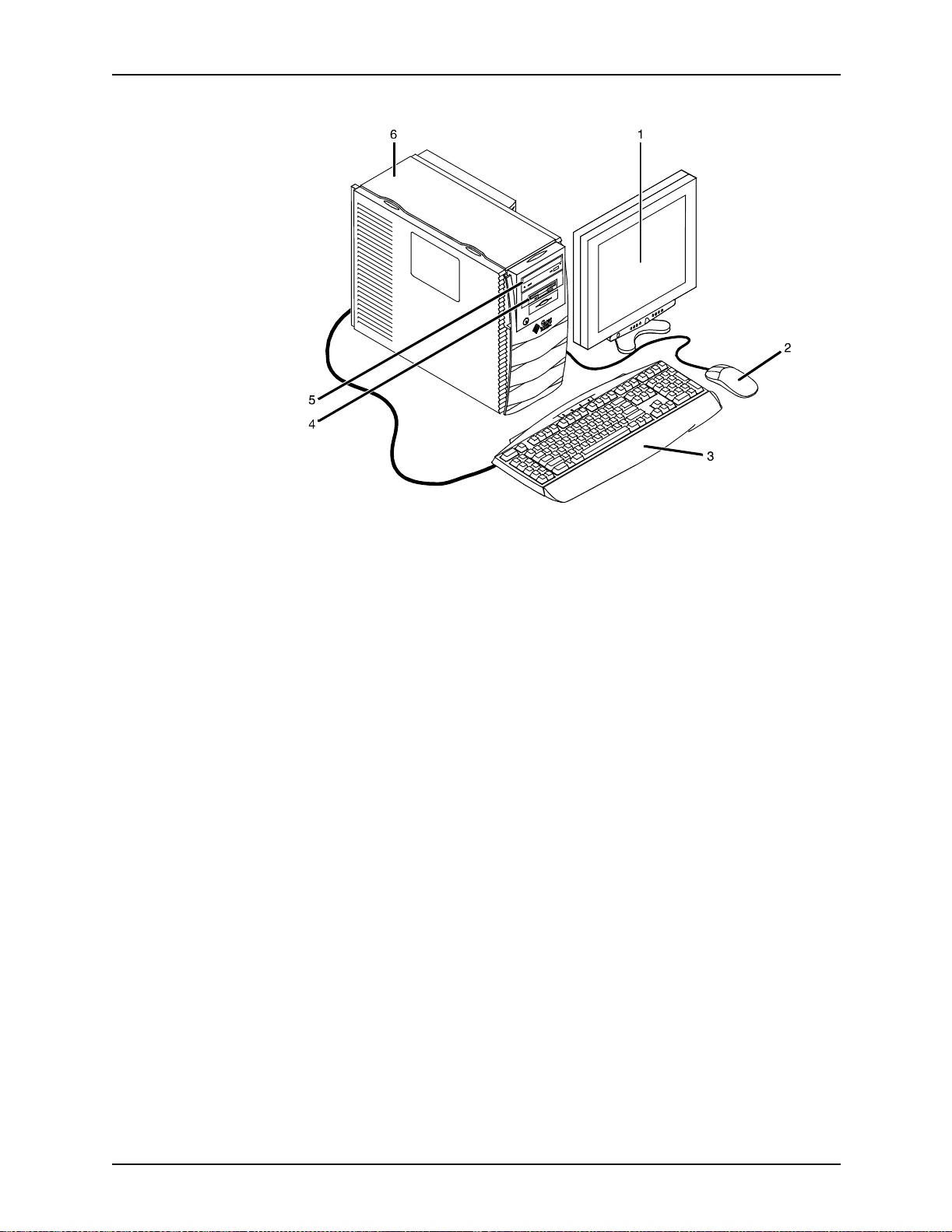
Figure 2-1. Components of the printer controller
1. Monitor
2. Mouse
3. Keyboard
4. Diskette drive
5. DVD-ROM drive
6. Processor
Processor The central processing unit contains the memory, internal disk
drive, a graphics board, a DVD-ROM drive, a diskette drive,
power receptacle and outlet, connectors and ports.
• Memory: Four 1 GB Dual In-line Memory Modules, or DIMMs
are provided as a standard feature of the processor.
• Hard disk drive: A 36 GB primary disk drive is provided as a
standard feature of the processor. The operating system, the
NPS/IPS applicat ion, and an y queued print jobs are stored on
the internal disk. This disk cannot be used to store other
applications or data except as directed by your service
representative.
• Graphics board: The Creator-3D series 3 graphics board is
provided as a standard feature of the processor.
System Overview Guide 2-3
Page 30
Printer controller overview
• Diskette drive: Diskettes inserted into a diskette drive are
• DVD-ROM drive: The DVD-ROM drive is a high density,
• Back panel: The back panel of the processor has a power
used to install fonts and to load files to, and back up files
from, the internal disk drive. The diskette drive uses industry
standard 3.5 inch, 1.44 MB, double-sided, high-density
diskettes.
read-only, optical laser storage device used for loading the
NPS/IPS operating system and other files. The CD-ROM
drive is located in the processor above the diskette drive.
receptacle an d outlet, conn ectors, connect or openings, and
ports. The following figure shows the back panel of the
controller.
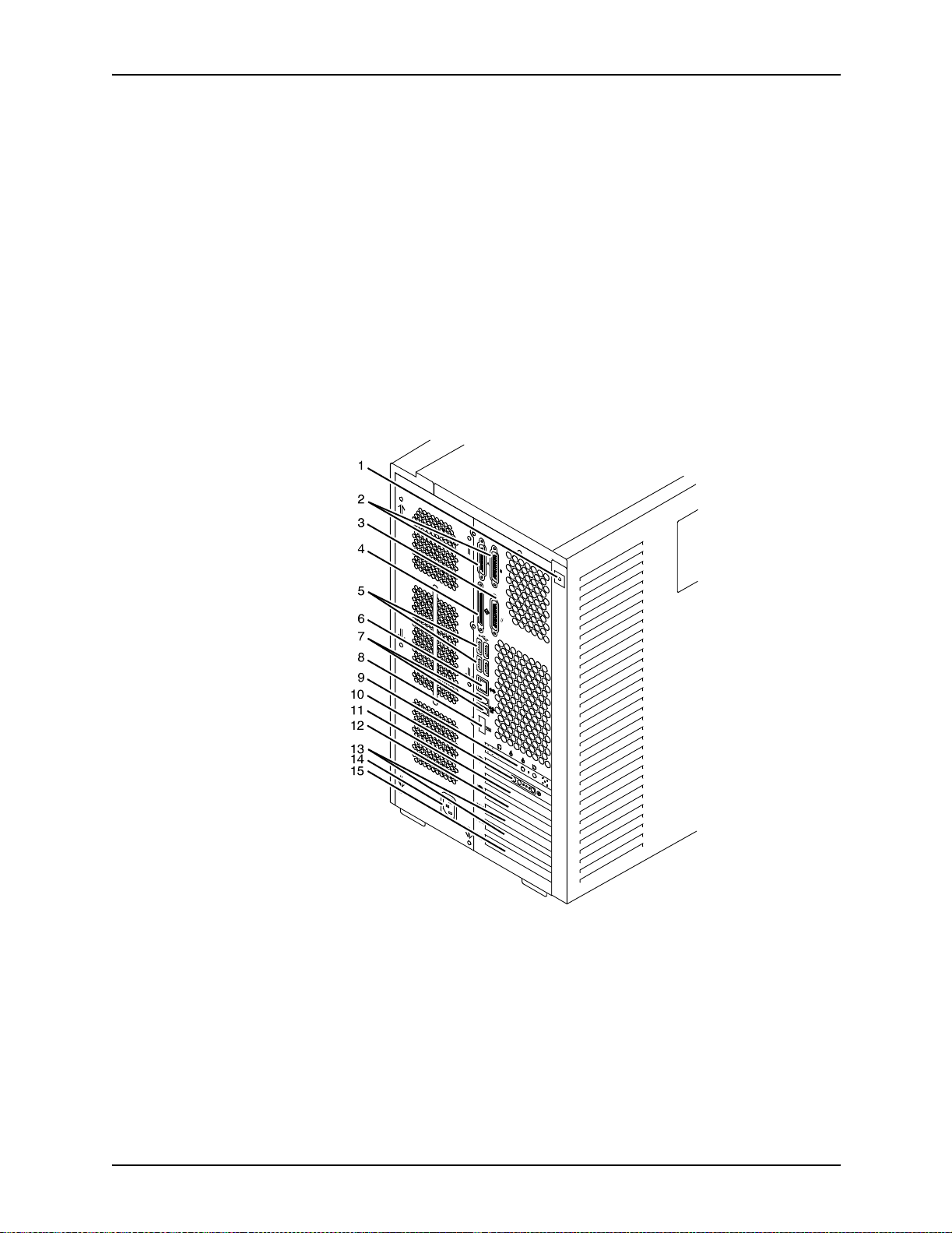
Figure 2-2. Back panel of the printer controller
1. Access panel lock block
2. Serial connectors A and B, DB-25
3. Parallel connector
4. SCSI connector
5. Universal serial bus (USB) connectors
2-4 System Overview Guide
Page 31

Printer controller overview
6. Twisted-pair Ethernet (TPE) connector
7. IEEE 1394 connector s
8. Fibre Channel-Arbitrated Loop (FC-AL) connector
9. Audio module headphones, line-in, line-out, and
microphone connectors
10.Graphics card / video connector (frame buffer 0)
11.PCI card slot 4
12.Graphics card / video connector (frame buffer not used)
13.PCI card slots 3 and 2
14.Power connector
15.PCI card slot 1
Keyboard The keyboard consists of alphanumeric keys similar to a
typewriter, symbols and special character keys, an extended
character set, and function keys. You can use the keyboard to
make selections, and to enter commands that control fu nctions
such as requesting sample prints, or shutting down the system.
Mouse Use the mouse to select, move, or resize the windows.
Display monitor The 18.1-i nch LC D mo nitor allo w s y o u to in ter act w ith th e printer
and to monitor its interaction with the various components.
During a print job, printer error messages may display to notify
you of any unexpected conditions.
NOTE: For information on channel-attached systems, refer to
the chapter, “IPDS printing enviro nment”.
NOTE: Printer controller hardware configurations are subject to
upgrade.
Sun Ultra 60 workstation
A PCIM2 card for the Sun Ultra 60 is installed in the processor.
The printer cable is connected to the processor. In addition, the
processor contains the connectivity boards for Ethernet and
optional Token Ring. The disk stores the operating system, the
system software, and any buffered pages.
System Overview Guide 2-5
Page 32

Printer controller overview
Optional
components
For channel connection to a host for IPDS printing, the system
may use an HCU.
An external 4 mm ta pe drive is available and recommended for
backing up site files. A typical color calibration file is 1.5 MB.
Figure 2-3. Printer controller components (Sun Ultra 60)
1. Monitor
2. Keyboard
3. Mouse
4. Processor
5. Diskette drive
6. CD-ROM
7. Optional cartridge tape drive
8. Optional HCU
Processor The central processing unit contains the memory, internal disk
drive, a CD-ROM drive, a diskette drive, power receptacle and
outlet, connectors and ports.
• Diskette drive: The floppy disk drive is located in the
processor. It uses industry standard 3.5 inch, 1.44-MB,
double-sided, high-den sity floppy disks. This disk drive is not
an input source for print jobs or for any other data or
application. It is reserved exclusively for use by a service
representative to update software and to store files.
2-6 System Overview Guide
Page 33

Printer controller overview
• CD-ROM: The CD-ROM drive, located in the processor
above the diskette drive, is a high-density, read-only, optical
laser storage device used for loading the software, fonts and
other files.
• Cartridge tape drive: The Sun Ultra 60 offers an optional 8
GB, 4 mm external SCSI cartridge tape drive. Unlike the
diskette and CD drives, this tape drive is not an input source
for print jobs or for any other data or application. It provides
the service representative with another means of loading
system maintenance files or saving diagnostic information.
Keyboard The keyboard consists of alphanumeric keys similar to a
typewriter, symbols and special character keys, an extended
character set, and function keys. You can use the keyboard to
make selections, and to enter commands that control fu nctions
such as requesting sample prints, or shutting down the system.
Mouse Use the mouse to select, move, or resize windows.
Display monitor The display monitor has a high-resolution color screen, which
displays the user interface screen.
NOTE: For information on channel-attached systems, refer to
the chapter, “IPDS printing enviro nment”.
NOTE: Printer controller hardware configurations are subject to
upgrade.
Printer controller software and fonts
The installation of printer controller software is performed by your
service representative once all the hardware components are in
place and properly connected. The following is a summary of
major software components installed on the printer controller:
• Xerox printer controller software
– UNIX Sun operating system
NOTE: The Sun operating system used on the controller
is based on the standard Sun operating system; however ,
it has been customized for use with the Xerox pr inter
controller. Therefore, not all standard Sun operating
system features are available.
System Overview Guide 2-7
Page 34

Printer controller overview
• Xerox Client Software
• Adobe Type 1 PostScript fonts
– DocuPrint Print Service Software including software
components for the user interface, driver, decomposers,
Job Pool Manager, and other operating system utilities.
– Xerox client protocol so ftware (print command) can be
downloaded to client workstations or PCs as a means of
sending jobs.
– Courier (Courier, Bold, Oblique, Bold Oblique)
– Helvetica (Helvetica, Bold, Oblique, Bold Oblique, Light,
Light Oblique, Black, Black Oblique Condensed,
Condensed Oblique, Condensed Bold, Condensed Bold
Oblique Narrow, Narrow Bold, Narrow Oblique, Narrow
Bold Oblique)
– ITC Av antGa rde Gothic (Book, Boo k Oblique , Demi, Demi
Oblique)
– ITC Bookman (Demi, Demi Italic, Light, Light Italic)
– ITC Garamo nd (Light, L ight Italic, Bold, Bold Italic)
– ITC Korinna (Korinna, Kursiv Regular, Bold, Kursive Bold)
– ITC Zapf Chancery (Medium Italic)
– ITC Zapf Dingbats (Medium)
– New Century Schoolbook (Roman, Bold, Italic, Bold Italic)
– Palatino (Roman, Bold, Italic, Bold Italic)
– Symbol (Medium)
– Times (Roman, Bold, Italic, Bold Italic)
Using font installation commands, you can load oth er Type 1
PostScript fonts in *.PFB file format from a MS-DOSformatted, 3.5-inch diskette or CD-ROM or DVD-ROM. Refer
to the Guide to Configuring and Managing the System for
more information on the font installation commands. Type 1
and Type 3 PostScript fonts can also be downloaded with a
print job.
• PCL fonts: Intellifont (scalable)
– CG Times (Medium, Italic, Bold, Bold Italic)
– Universe (Medium, Italic, Bold, Bold Italic)
– Universe Condensed (Medium, Italic, Bold, Bold Italic)
– Courier (Medium, Italic, Bold, Bold Italic)
2-8 System Overview Guide
Page 35

Printer controller overview
– Letter Gothic (Medium, Italic, Bold)
– Albertus [Medium (semi-bold), Extra Bold
– Antique Olive (Medium, Italic, Bold)
– Clarendon Condensed (Bold)
– Coronet (Medium Italic)
– Garamond [Antique (medium), Kursiv (Italic), Halbfett
(Bold), Kursiv Halbfett (Bold Italic)]
– Marigold (Me di um )
– CG Omega (Medium, Italic, Bold, Bold Italic
• PCL fonts: Truetype (scalable)
– Arial (Medium, Italic, Bold, Bold Italic)
– Times new Roman (Medium, Italic, Bold, Bold Italic)
– Symbol (Medium)
– Wingdings (Medium)
• PCL fonts: Bitmap
– Line Printer (16.67 pitch / 8.5 point medium)
NOTE: The resident fonts are used for PostScript and PCL
printing.
System Overview Guide 2-9
Page 36

Printer controller overview
2-10 System Overview Guide
Page 37

Printer components
3. Printer components and options
The printer processes the electronic data and images received
from the control ler and p roduces th e printed out put. This ch apter
describes the components and options available for the printer.
The components of the 4635 and 180 NPS/IPS base printer are
shown in the following figure. The 96 NPS/IPS standard printer
configuration has one inve rter feeder/stacker module, with the
option of adding a second feeder/stacker module as shown.
Figure 3-1. DocuPrint 96, 4635, and 180 printer components
1. Printer console
2. Sample tray
3. Attention light
4. Purge tray
5. Feeder/stacker module
6. Feeder/stacker module with inverter
7. Processor feeder trays
System Overview Guide 3-1
Page 38

Printer components and options
NOTE: The DocuPrint MICR NPS/IPS models utilize the same
hardware and operating system as the non-MICR NPS/IPS
models. However, the Image Development systems have been
modified to enable MICR font reproduction.
Processor feeder
trays
Feeder tray contr ol
panels
Two processor feeder trays are located in the main part of the
printer:
• The main tray (tray 1) holds up to 1100 sheets of 20 pound or
80 gsm (grams per square meter) paper.
• The auxiliary tray (tray 2) holds up to 600 sheets of 20 pound
or 80 gsm paper.
Each tra y can handl e paper from 8 x 10 inches/203 x 25 4 mm
to 9.02 x 14.33 inches/230 x 364 mm.
Each processor feeder tray and HCF tray has a control panel
consisting of a button, indicators, and paper level displays.
Ready
Please
to open
1
Tray
wait
unload
34
2
Figure 3-2. Feeder tray control panel
1. Ready to Open indicator
2. Please Wait indicator
3. Tray Unlock button
4. Paper Level indicators
1. Ready to Open indicator
This indicator glows when paper can be added to the tray.
2. Please Wait indicator
This indicator shows that the tray is in motion. It is lit when
the Tray Unlock button is pressed, when the tray is being
lowered, or when the tray is being raised. The indicator goes
off when the tray elevator reaches its destination.
3-2 System Overview Guide
Page 39

Printer components and options
3. Tray Unlock button
You can use this button any time the Please Wait indicator is
off.
• If the tray is in use when this button is pressed, the feed
selection changes to the backup tray if one exists.
Otherwise, printing stops.
• If the tray is in use and s elected as a backup tray,
pressing this button causes the tray elevator to lower and
the tray is no longer available for auto switching.
• If the tray elevator is in the raised position and the tray is
not in use or selected as a backup tray, pressing this
button causes the elevator to lower with no effect on
printing operations.
4. Paper Level indicators
These indicators display the approximate quantity of paper
within the tray. The display shows paper by quarter reams up
to one ream, and t hen by full reams. The green indica tor ligh t
appears above the Paper Level indicator which shows the
amount of paper in the tray.
7 by 10 inch /
178 by 254 mm
enablement
Inverter The inverter is part of the inverter feeder/stacker module. It
High-capacity
feeder
The optional 7 by 10 inch enablement feature allows your
DocuPrint 4635 and 180 NPS/IP S to p rint on pa per si z e d fr om 7
by 10 inches / 178 by 254 mm to 9.02 by 14.33 inches/
230 by 364 mm.
NOTE: The 7 by 10 inch enablement feature is not available on
the DocuPrint 96 NPS/IPS.
allows for proper collation of the print job. It directs printed output
to the sample tray, when required. It also directs output to
optional third-party finishing devices in the proper orientation.
There is a high-capacity feeder (HCF) tray located in the bottom
half of each feeder/s tacker module (trays 3, 4, 5 and 6,
depending on the number of feeder/stacker modules installed).
Each HCF tray can hold up to 2600 sheets of 20 pound or 80
gsm paper.
System Overview Guide 3-3
Page 40

Printer components and options
NOTE: When configured, each HCF tra y can han dle paper sized
from 7 by 10 inc hes / 178 b y 254 mm to 17 b y 14.33 i nches / 432
by 364 mm. To feed papers smaller than 8 inches / 203.2 mm, an
optional 7 by 10 inch enablement kit must be installed. 17-inch/
432 mm paper ca n be fed only short edge first .
An elevator moves the tray up or down when it is in use. The
HCF trays have Paper Level switches which detect the position
of the elevator to determine the fullness of the tray. Paper Size
switches detect the size of the paper loaded in the trays.
High-capacity
stacker
The 4635 and 180 NPS/IPS printers can contain up to four highcapacity stacker (HCS) bins as part of the feeder/stacker
modules (stacker bins A, B, C and D). The 96 NPS/IPS printer
can contain up to two high-capacity stacker (HCS) bins as part of
the feeder/stacker modules (stacker bins A and B).
Figure 3-3. High-capacity stackers
Each HCS can hold 2500 sheets of 20 pound or 80 gsm paper
stacked on the bin platform.
NOTE: For large paper sizes such as 11 by 17 inches or A3,
there is a stack limit of about 1500 sheets. This limit is needed to
keep the total weight of the stack within safe limits for unloading
and lifting.
A stacking elevator maintains the paper at the prop er level for
stacking and lowers the stack for unloading. There is an offset
mechanism that offsets printed sets toward the front or back of
the HCS bin. Each HCS bin has unlink ed doub le doors to pro vide
you with easy, yet safe, access for unloading paper from the
printer.
3-4 System Overview Guide
Page 41

Printer components and options
Figure 3-4. High-capacity stacker bin control panel
1. Ready to Unload indicator
When this indicator glows, you can remove printed sheets
from the sta cker bin.
2. Please Wait indicator
When this indicator glows, the elevator is in motion. This
indicator goes off when the platform reaches its destination.
3. Bin Unload button
Pressing this button causes the bin elevator to lower. If the
bin is in use and is part of a STACKER GROUP combination,
the printed pages begin stacking in the other stacker bin. If
the bin is not in use, there is no effect on printing operations.
If this is the only bin in a ST ACKER GROUP, printing will stop.
4. In Use indicator
When this indicator glows, the bin is selected to receive the
next printed shee t.
Purge tray The purge tray is located on top of the feeder/stacker module.
Aborted sheets (for example, damaged sheets o r sheets clear ed
after a paper jam) are sent to this tray. The purge tray can hold
up to 100 sheets of paper.
Attention light An attention light is mounted on top of the inverter module. The
attention light signals when the printer requires operator
attention:
• Off: No printer problems exist that require your attentio n.
• Steady light: A situation exists that needs your attention
(such as low dry ink condition).
• Flashing: The printer has stopped and requires your
attention immediately.
System Overview Guide 3-5
Page 42

Printer components and options
NOTE: When the attention light starts flashing, an explanatory
message appears on the printer console display. A similar
message appears on the printer controller screen.
Sample button The Sample button on the 180, 4635, or 96 printer duplicates
one of the shee ts in the paper path and delivers it to the sample
tray. This sheet can be used to check quality an d alignment w hile
printing. The button is disabled for MICR printers.
Sample tray The sample tray located on top of the printer holds up to 100
sheets of paper. It receives output such as transparencies,
sample prints or system files, and waste sheets that cannot be
sent to the purge tray.
Printer console The printer console is the color monitor located on top of the
printer. It contains message ar eas and gr aphic displa ys that ale rt
you to paper jams and other fault conditions, such as low toner.
The printer console also contains buttons that allow you to
control certain functions of the printer, such as continuing an
interrupted job, without returning to the printer controller.
The printer console has the following features:
• Local controls and displays for jam clearance, paper loading/
unloading, and diagnostics/se rvice (used by the service
representative). Two types of message s ar e d i splayed on the
printer console: fault messages, which relate to printer
malfunctions, and information messages, which relate to
printer conditions such as low dry ink.
• Touch-sensitive areas that allow you to select options by
touching the printer console screen. A tone sounds when you
touch one of these areas.
• Printer alarm consisting of three beeps, repeated for ten
seconds. The alarm is generat ed by any event that stops the
printer.
The alarm stops after three cycles or as soon as you start to
clear the fault condition (for example, when you open doors or
covers specified in the clearance instructions). You can stop the
alarm by pres sing one of the printer console buttons or by
selecting a function through the touch screen.
3-6 System Overview Guide
Page 43

Printer components and options
12345
12
11
Ready
Printer Options
Clear
6
7
8910
Figure 3-5. Printer console
1. Language icon
2. Printer icon
3. Fault List icon
4. Tools icon
5. Guarded Tools icon (not available on the 96 NPS)
6. Clear but t on
7. Continue button
8. Stop button
9. Sample b ut ton
10.Brightness control thumbwheel
11.Icon area
12.Message area
System Overview Guide 3-7
Page 44

Printer components and options
Printer configurations
The DocuPrint 96 NPS/IPS base system is configured with one
inverter feeder/stacker module; one additional feeder/stacker
module is optional. Input enablement and bypass transport
devices can also be used.
NOTE: The input enablement and bypass transport devices are
offered as optional components. These options allow you to
customize your printer for increased efficiency and specia lized
applications, such as roll feed and finishing devices. The middle
feeder/stackers are also optional for the 4636 and 180 NPS/IPS.
The DocuPrint 96, 4635, and 180 NPS/IPS are available in the
following configurations, some of which may include the bypass
transport and/or Input Enablement kit.
Figure 3-6. DP 96 NPS/IPS: Printer + inverter feeder/stack er
The DocuPrint 4635 and 180 are available in the configurations
shown in the following figures.
Figure 3-7. Printer + inverter feeder/stacker + feeder/stacker
3-8 System Overview Guide
Page 45

Printer components and options
Figure 3-8. Printe r + inverter feeder/stacker + feeder /stacker
+ feeder/stacker + bypass transport
Figure 3-9. Printe r + inverter feeder/stacker + feeder /stacker
+ feeder/stacker
Figure 3-10. Printer + inverter feeder/stacker + feeder/
stacker + feeder/stacker + bypass transport
Figure 3-11. Printer + inverted feeder/stacker + feeder/
stacker + feeder/stacker + feeder/stacker
System Overview Guide 3-9
Page 46
Printer components and options
NOTE: The bypass transport device is not available for this
configuration four feeder/stacker modules). The Input
Enablemen t ki t i s available for this configuration on the 180 NPS/
IPS only.
Paper paths
The paper path is the route that materials (paper,
transparencies, labels, and so on) follow through the printer from
the feeder trays to the output trays.
Paper path
through the printer
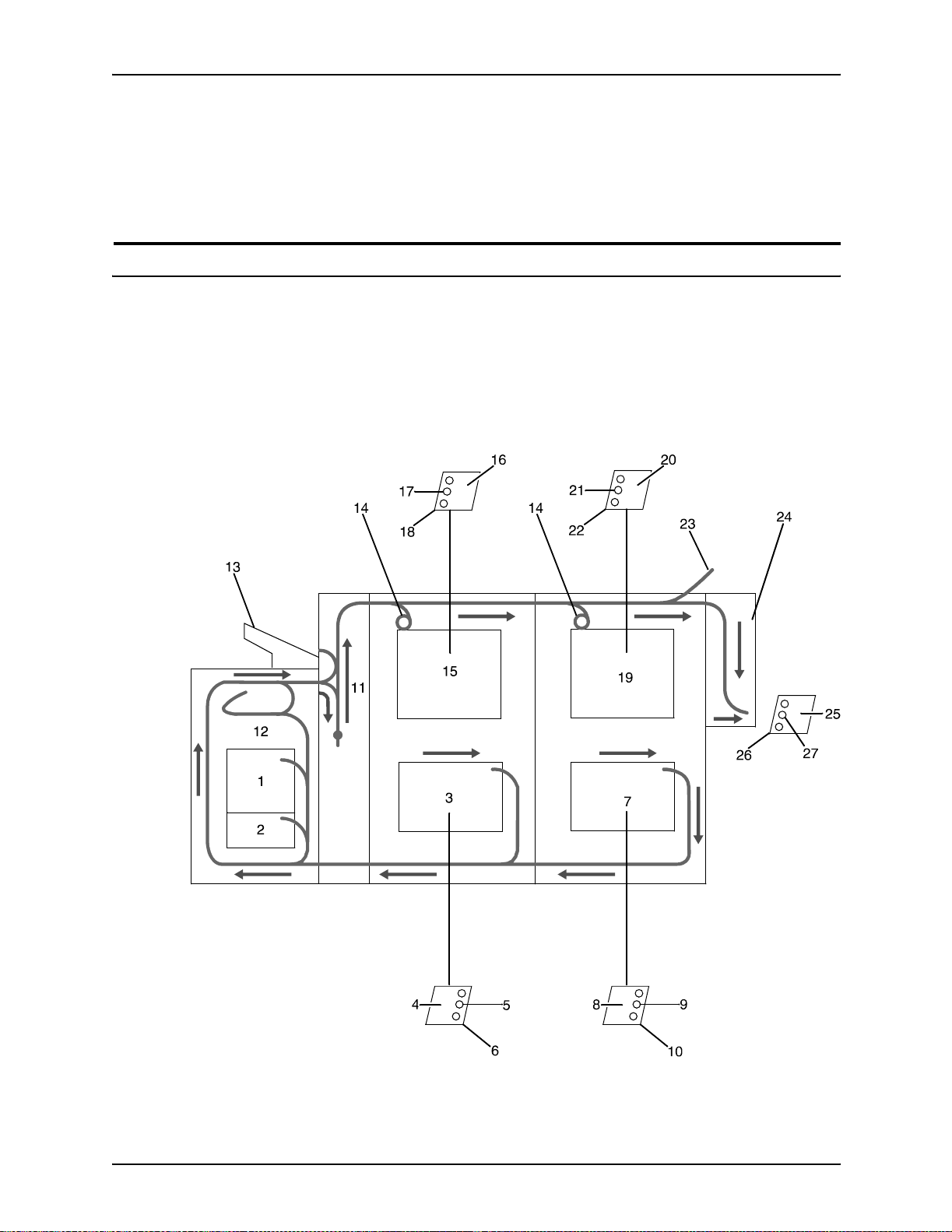
The following figure illustrates the entire printer paper path.
Figure 3-12. Route of paper through 96/4635/180 printer
3-10 System Overv iew Guide
Page 47

Printer components and options
1. Processor feeder tray 1
2. Processor feeder tray 2
3. High-capacity feeder tray 3
4. Side 1 of sheet leaving feeder tray
5. Drilled holes (on right edge)
6. Origin 0,0: portrait feeder tray 4
7. High-capacity feeder tray 4
8. Side 1 of sheet leaving feeder tray
9. Drilled holes (on right edge)
10.Origin 0,0: portrait feeder tray 4
11.Inverter
12.Duplex inverter
13.Sample tray
Input enablement
paper path
14.Disk inversion
15.High-capacity stacker bin A
16.Side 2 of sheet stacked in bin
17.Drilled holes (on left edge)
18.Origin 0,0: portrait orientation
19.High-capacity stacker bin B
20.Side 2 of sheet stacked in bin
21.Drilled holes (on left edge)
22.Origin 0,0: portrait orientation
23.Purge tray
24.Bypass transport
25.Side 2 of shee t passing through bypass transpo rt
26.Drilled holes (on left edge)
27.Origin 0,0: portrait orientation
The follo wing figu re sho ws the paper path and the dimensio ns of
the input enablement area from a printer front view. The input
enablement kit option supports third-party feeding d evices.
System Overview Guide 3-11
Page 48

Printer components and options
Figure 3-13. Input enablement paper path and dimensions
The following figure shows the dimensions of the bypass
transport portion of the paper path.
3-12 System Overv iew Guide
Page 49

Printer components and options
Figure 3-14. Bypass transport dimensions
System Overview Guide 3-13
Page 50

Printer components and options
3-14 System Overv iew Guide
Page 51

4. Network printing environment
The NPS/IPS system su pports the person al comp ut er (PC) , Sun
workstation, DEC workstation, HP/Apollo, IBM RS/6000 and
Apple Macintosh. It accepts PostScr ipt levels 1 and 2, PCL 5,
TIFF, and ASCII output.
Client workstations and system software
To send print jobs to the printer, the customer needs to provide
the proper client hardware, operating system, and network
software.
Print data originates at the client workstation, mainframe or
minicomputer. This is where a user creates and formats
documents according to specifications with the help of
application software. The printer supports the following types of
networked client workstations and operating systems:
• Sun workstation running a Sun or Linux operating system
• PC running MS-DOS 6.2 and Microsoft Windows 95, 98, NT,
4.0, 2000, and ME using Ethernet with TCP/IP or Novell
NetWare 3.11 and 3.12.
NOTE: Customers using Novell 4.1 must set the “Bindery
Emulation Mode” to be backwards compatible with Novell 3.11
and 3.12.
• IBM RS/6000 running IBM AIX, version 4.1
• HP/Apollo running HP-UX, version 10.01
• DECStation 5000/200 running DEC Ultrix, version 4.3
• Apple Macintosh, System 7, 7.5, or 8.x, using AppleTalk
through EtherTalk, phase 1 or 2
• Any system that supports RFC-1179 lpr/lpd.
The software may be compatible with workstation models and
software versions other than those listed above.
System Overview Guide 4-1
Page 52

Network printi ng environment
Client software
On your PC or workstation, you must install or set up a
supported means of submitting jobs to the printer. Depending on
your system, you can use the following:
• Xerox drivers for Windows 3.x, 95/98, or NT/2000
• Xerox Document Submission Software for DOS, Windows
3.x, 95/98, NT/2000, or Macintosh
• Third-party dr ivers
– Some PostScript drivers can be used in conjunction with
– HP Color LaserJet for PCL 5c jobs
– HP LaserJet 4 fo r monochrome jobs
• Third-party TCP/IP lpd utility
• Apple/Macintosh Printer Access Protocol (PAP)
Xerox-supplied PPD files
NOTE: The printing options vary according to the network
software that is loaded on the client workstation.
Submitting print jobs
There are basically two ways you can submit print jobs: You can
send print data directl y fro m the ap pl i cati on to the printer; or y o u
can create a PDL data file on the workstation and then send the
data file to the printer. The method you choose depends on the
workstation configuration and the job submission requirements.
Sending the print data directly from the application to the printer
is accomplished with a Xerox print driver or a third-party driver.
This method is sometimes referred to as “transparent printing.” It
may not support all available print options, such as number of
copies, simplex or duplex printing, and stitching.
The other way to submit print jobs to the printer is by creating a
PDL data file. After the file is created, the user closes the
document and submits the job using one of the following
methods:
• lpr command: Provides opt ions fo r submitting prin t jobs. The
functionality of the lpr command is dependent on the TCP/IP
software installed on the workstation.
4-2 System Overview Guide
Page 53

Network printing enviro nm en t
• Xerox Client Software: Provides a print command for
submitting jobs and s pecifyi ng print op tions . Th e fun ction ality
of the print command is dependent on the TCP/IP software
installed on the workstation.
• Xerox DocuPrint Document Submission Client software
for the Macintosh: Provides a graphical user interface for
submitting jobs and specifying print options.
• Xero x DocuPrint Print Submis sion software f or Windo ws
3.x, Windows 95/98, Windows NT, and Windows 2000:
Provides graphical user interfaces for submitting jobs a nd
specifying print options.
• Internet Printing Protocol for Windows 2000: Allows job
submission over the Internet.
In many cases, the workstation can be set up for more than one
method of job submission.
The application software provides the capability to print the
document using a page description language (PDL). The
application produces print data in one of the supported page
description language formats, for example PostScript level 2.
Communicating with the network
After the print data has be en pr epar ed for printing and combined
with print options data—eithe r by the application soft ware or by a
print job submission u tility—t he prin t jo b is sent o ver the network.
The printer supports TCP/IP, AppleTalk, and Novell NetWare
network communic ations protocols.
Client workstations require a network software utility that submits
the job using the appropriate network protocol. This software
must be installed an d running for jobs to be submitted
successfully to the printer . Once this software is installed, its
operation is transparent to the user.
The Macintosh uses Printer Access Protocol (PAP) to
communicate with one or more DocuPrint printers. For
convenience, your internet may be divided into zones. A zone
can be any logical group i ng of individual workstations and
printers. Your ne twork administrator defines your zone when
setting up the network.
System Overview Guide 4-3
Page 54

Network printi ng environment
Shown below are the workstations, networking options, and job
submission methods available for each client.
Table 4-1. Clients
Client
workstation
hardware
Sun
Microsystems
IBM PC and
compatible
IBM PC and
compatible
IBM PC and
compatible
Operating
system
Solaris
SunOS
MS-DOS Optional
Windows 3.1 Optional
Windows 95/98Optional
Ethernet
connection
Standard TCP/IP;
Ethernet
interface card
(for example,
3Com 3C503)
Ethernet
interface
Ethernet
interface
Protocol;
Translation
requirements
none
TCP/IP;
network
communication
utility recommended
TCP/IP or Novell
Netware 3.1x;
network
communication
utility recommended
with TCP/IP
TCP/IP or Novell
Netware 3.1x;
network
communication
utility recommended
with TCP/IP
Job submission
method
Print using the lpr
command or Xerox
Client Software.
Print to disk file, then
send using the lpr
command or Xerox
Client Software.
Print directly from
application or use Xerox
DocuPrint Print
Submission software for
Windows.
Print directly from
application or use Xerox
DocuPrint Print
Submission software for
Windows.
IBM PC and
compatible
IBM PC and
compatible
Digital
Equipment
Corporation
DECstation
Windows NT Opti ona l
Ethernet
interface
Windows
2000
ULTRIX Optional
Optional
Ethernet
interface
Ethernet
interface
TCP/IP or Novell
Netware 3.1x;
network
communication
utility recommended
with TCP/IP
TCP/IP or Novell
Netware 3.1x;
network
communication
utility recommended
with TCP/IP
TCP/IP;
none
Print directly from
application or use Xerox
DocuPrint Print
Submission software for
Windows.
Print directly from
application or use Xerox
DocuPrint Print
Submission software for
Windows, or the Internet
Printing Protocol (IPP)
Print directly from
application, or use the
lpr command or Xerox
Client Software.
4-4 System Overview Guide
Page 55

Table 4-1. Clients (Continued)
Network printing enviro nm en t
Client
workstation
hardware
Apple
Macintosh
IBM RS/6000 IBM AIX Standard TCP/IP;
HP/Apollo HP-UX Standard TCP/IP;
Operating
system
Apple OS Optional
Ethernet
connection
Ethernet
interface
Protocol;
Translation
requirements
AppleTalk using
EtherT alk Phase I or
II; none
none
none
Job status feedback
Client workstations display fault messages and additional
information, such a s th e sta tus of fee de r trays and o utp ut bi ns. If
properly configured, the workstations may be able to display job
status, as shown below.
Job submission
method
Print directly from
application or use Xerox
DocuPrint Print
Submission Client
software for the
Macintosh.
Print using Xerox Client
Software.
Print using Xerox Client
Software.
Table 4-2. Job status feedback
Platform Job status capability
Sun workstation Job status and job deletion are available by issuing the appropriate
command at the command line.
Job status information is available for jobs submitted using Xerox Client
Software.
IBM and compatible
personal computers
Apple Macintosh Job status information is available at the workstation through AppleTalk.
IBM RS/6000 and HP/
Apollo
Job status and job deletion are available depending on the TCP/IP
software installed on the workstation. You must issue the appropriate
command at the command line.
Job status information is available for jobs submitted using Xerox Client
Software.
Job status information is available using the Novell PCONSOLE utility if
the printer is configured with a RPRINTER or PSERVER enabled.
Job status information is available for jobs submitted using Xerox Client
Software or Ipstat (native utility).
To determine the status of jobs submitted using the lpr
command, you must issue an lpq command at the command line.
Some application software packages may provide a simplified
means of obtaining job status, such as through the use of icons.
System Overview Guide 4-5
Page 56

Network printi ng environment
The job status command (lpq) is available at client workstations
unless your TCP/IP network communication s utilities do not
support it.
Xerox Client Software provides commands for listing the status
of the job and for listing the queue. These command s are
available fo r jobs submitted using Xerox Client Software.
AppleTalk provid es job status information at the client
workstation throu gh the print mon itor functio n. Wo rkstation users
can also determine the status of a virtual printer.
NOTE: Job status is also available by establishing a telnet
connection to the Printer Controller to access the user interface
from your w orkstation. Printer and ad ditional status inf ormation is
also available. You can also use a Web browser to obtain job
status. See the Guide to Configuring and Managing the System
for more information.
Ethernet LAN
Token Ring
Users of networke d client workstatio ns may send print jobs to the
printer ov er th e E the rnet LAN using ei th er th e TCP/IP, AppleTalk
using EtherTalk Link Access Protocol (ELAP), or Novel l NetW are
as the network protocol.
Regardless of printing or transmission protocol, the Ethernet
connection to the Printer Controller must be compatible with the
Institute of Electrical and Electronics Engineers (IEEE) 802.3
standard.
Users of networke d client workstatio ns may send print jobs to the
printer ove r a Token Ring network using TCP/IP, Nov ell NetWare
or AppleTalk network protocol.
Regardless of the prin ti ng transmission protoco l, the Token Ring
connection to the Printer Controller must be compatible with the
Institute of Electrical and Electronics Engineers (IEEE) 802.5
standard.
4-6 System Overview Guide
Page 57

Multiple network connectivity
The system supports multiple network connectivity, that is, the
ability for protocols such as TCP/IP to run on more th an one
network interface. For TCP/IP, the system can support any
combination of Ethernet or Token Ring. One interface is
designated as the primary network interface. Novell NetWare
can run on only the primary network interface, but the type of
interface can be selected.
AppleTalk c an run on on ly one network interface, but it does not
have to be the primary one.
Network printing enviro nm en t
System Overview Guide 4-7
Page 58

Network printi ng environment
4-8 System Overview Guide
Page 59

Host connectivity
5. IPDS printing environment
The NPS/IPS emulates an IBM AFP Group 3 page printer with
the Advanced Function Image and Graphi cs (AFIG) option. It can
print in all the following PSF environments: MVS, VM (channelattached only), V SE ( c h an nel - at tach ed onl y, OS/2, OS/400 (with
TCP/IP only), and AIX.
NOTE: Although PSF/VSE does not support TCP/IP directly, a
printing system with PSF/2, PSF/6000, or IBM Inf oPrint Manager
can attach to a PSF/VSE system and the PSF/2, PSF/6000, or
IBM InfoPrint Manager can furnish the TCP/IP support for the
printer.
Host environments
The system emulates an IB M A FP G roup 3 p age printer with t he
Advanced Function Image and Graphics (AFIG) option and can
print in all the following PSF environments:
•MVS
• VM (channel-attached only)
• VSE (channel-attached only)
•OS/2
• OS/400 (with TCP/IP only)
•AIX
NOTE: Although PSF/VSE does not support TCP/IP directly, a
printing system with PSF/2, PSF/6000, or Inf oP rint Manager can
attach to a PSF/VSE system and the PSF/2, PSF/6000, or
InfoPrint Mana ge r can furnish the TCP /IP support for the printer.
NOTE: There is no minimum host operating system software
level required. The minimum PSF level needed to support full
color is v.3.2.
System Overview Guide 5-1
Page 60

IPDS printing environment
The NPS/IPS can be set up to receive data from the IBM host in
one of two ways:
• Through a bus and tag channel connection.
• Through a Token Ring or Ethernet interface using TCP/IP.
NOTE: If your system will be channel-attached, the printer
controller requires an additional component—either a
channel interface board and channel cable connector box, or
a Host Channel Unit (HCU) that serves as an interface
between the IBM host and the printer controller.
NOTE: Your system supports only one other connectivity
option in addition to Ethernet. For example, Ethernet and
channel connection or Ethernet and Token Ring.
NOTE: A transmission ra te of at least 16 megabits per
second should be used with a Token Ring interface. (Overall
performance depends on network traffic and job density.)
1
IBM
Host
7
4
6
5
3
2
Figure 5-1. Printing system: channel-attached configuration
1. Host system (PC or mainframe)
2. Printer
3. Printer interfac e cables
4. Printer control ler
5. Internal channel cable
6. Host Channel Unit (HCU)
7. Bus and tag cables
5-2 System Overview Guide
Page 61

IPDS printing environm ent
Figure 5-2. Printing system: TCP/IP configuration
1. Host system (PC or mainframe)
2. Interface network (Ethernet or Token Ring)
3. Printer control ler
4. Printer interfac e cables
5. Printer
For in formation on the various printer configuration options, refer
to the “Printer components and options” chapter of this guide.
Channel interface —channel-attached systems only
Your system may use a channel interface board and connector
box for channel connection to a ho st for IPDS printing. The
channel interf ace board, connected to a channel cab le connector
box, handles all IPDS communications and handshaking with
PSF on the host when the NPS/IPS is receiving data over a
channel. (It is not used when the NPS/IPS is printing data using
TCP/IP.)
System Overview Guide 5-3
Page 62

IPDS printing environment
Figure 5-3. Channel board and control unit
1. Printer
2. Printer control and video cable
3. Printer controller with channel interface board
4. Channel cable connector box
5. Channel cables
6. Host system
NOTE: The customer is r esponsible for obtaining, stringing, and
maintenance of the bus and tag cables. The bus and tag cables
must be fully populated cable sets.
Host Channel Unit (HCU)—channel-attached systems only
Your system may use a Host Channel Unit (HCU) for channel
connection to a host for IPDS printing.
The HCU handles all IPDS communications and handshaking
with PSF on the host when the system is receiving data over a
channel. It is not used when the system is printing data using
TCP/IP.
5-4 System Overview Guide
Page 63

IPDS printing environm ent
Figure 5-4. Host Channel Unit (HCU)
The front panel of the HCU provides a single-digit LED display
that enables you to monitor power-up and offline status, and
alerts you to error conditions. (Refer to the Messages Guide for
an explanation of the HCU codes.)
The back panel of the HCU has a power switch and outlet, bus
and tag cable input and bypass connectors, and a dual serial
port.
NOTE: The customer is r esponsible for obtaining, stringing, and
maintenance of the bus and tag cables. The bus and tag cables
must be fully populated cable sets.
IPDS data stream
All IPDS resources (print data sets, page definitions, form
definitions, page segments, fonts, and overlays) that are
supported by the IBM 3825 and 3827 printers are supported by
the Xerox software. Additionally, the data towers that are
supported within the AFP en vironmen t by the IBM 3825 an d IBM
3827 printers are fully supported by the software. Data towers
supported are:
• IM Image IMD1
• FOCA: Font Object Content Architecture
• MO:DCA-P: Mixed Obj ect Document Cont ent Architecture f or
Presentation
• PTOCA PT1, PT2, and PT3: Presentation Text Object
Content Architecture
• IOCA: Image Object Content Architecture
• GOCA: Graphics Object Content Architecture
• BCOCA: Bar code Object Content Architecture
System Overview Guide 5-5
Page 64

IPDS printing environment
• OL1: Overlay One
• PS1: Page Segment One
• Line mode data streams
Each of the data objects f ollo w the same object rule of conta ining
delimiting fields with structure d fields describing each object.
Software features for IPDS
This section describes some of the software features for IPDS
printing.
IOCA Replicate and Trim
The printer supports Replicate and Trim, which improves the
processing of IM and IO images that contain large areas of
shaded graphics. (IM images are resolution-dependent images
that cannot be compressed or scaled; IO images are resolutionindependent.)
The IOCA Replicate and Trim capability allows for faster
transmission to the printer of AFP applications with IM images
that have large or widespread shaded areas. It also reduces the
storage area required on the host and on the printer.
Tr ace facility
To help diagnose problems, the system provides a trace
mechanism. Trace files store system configuration information,
maintain TCP/IP protocol headers, and time-stamp all records.
For detailed information on this feature, refer to the “Using utility
commands” chapter in the Guide to Configuring and Managing
the System.
Overstrike, underscore, subscript, and superscript
Support for the PT2 Subset of PTOCA enables the printer to
print overstrikes, underscores, subscripts, and superscripts
where specified in jobs.
5-6 System Overview Guide
Page 65

Color image support
Some IM1 images (for example, logos) can be converted to
IOCA for resolution corre ction. The bi-le v el IOCA f eature ena bles
such IM1 images to be printed in color on the highlight-color
printer. PSF does not strip the color information from the print
job.
Also supported are JPEG compressed IOCA, as well as JPEG
and EPS files in object containers.
NOTE: Hosts may not support JPEG files in object containers.
Background color for OCA colors
Users can specify COLOR on DRAWBOX (i.e., ba ckground
color) as long as the color is restricted to colors defined with the
OCA model.
IPDS printing environm ent
Bi-level IOCA colors
The printer accepts the new IOCA color spaces in the extended
controls (ref erred to as the “4E” col or trip lets) . Th ese in cl ude th e
Highlight Color and Standard OCA Color.
Outline font support
The printer su ppor ts the use of IBM outline fonts for both singlebyte and double-byte applications. These fonts must be
downloaded during the jobs.
These outline fonts allow users to specify a single font that can
be rasterized in a variety of point sizes by the printer. The IBM
outline f onts ar e based on Adob e type 1 and type 0 f on ts that a re
in Post Script format.
System Overview Guide 5-7
Page 66

IPDS printing environment
5-8 System Overview Guide
Page 67

6. Magnetic ink character recognition
(MICR)
96/4635/180 MICR NPS/IPS printing features
The 96, 4635, and 180 MIC R NPS/I PS meet ABA stand ards and
ANSI and ISO specificati on s for automatic check handling.
These printing systems print the MICR line and the rest of the
check at the same time, which reduces processing time and
cost. Their special features include the following.
MICR fonts Xerox provides a set of 300 dpi MICR fonts for use on the 96/
4635/180 MICR NPS/IP S. You must use only these Xeroxsupplied MICR fonts to have the high print quality Xerox
guarantees.
The 96/4635/180 MICR NPS/IPS creates machine-readable
documents using the standard E13B and CMC7 fonts. These
fonts support 14 characters, including the numerals zero through
nine.
The “Test” fonts are non-readable MICR hollow bitmap (or
outline) fonts, provided for testing MICR appl ications and printing
non-negotiable documents.
E13B font set: The E13B series includes:
• E13B
• E13B Landscape
• E13B Te st
• E13B Te st Landscape.
System Overview Guide 6-1
Page 68

Magnetic ink character recognition (MICR)
CMC7 font set: The CMC7 set is an alternative set of MICR
fonts that has been adopted in various co untries out side the
U.S., and is the official standard in France. Like the E13B font, it
is magnetically readable, but with a different character design
and recognition criteria. The series includes:
•CMC7
• CMC7 Landscape
•CMC7 Test
• CMC7 Test Landscape.
Check
Performance
Guarantee
300/600 dpi
resolution
Transfer Assist
Blade
The Xerox Check Performance Guarantee means Xerox stands
behind the performance of its MICR printers and inks. However,
if any E13B or CMC7 font is used other than the ones supplied
by Xerox, this guarantee is invalidated.
The 96/4635/180 MI CR receiv es data at 300 dpi and interpolates
it to print at 600 dpi. All AFP resources, including fonts, required
for MICR print jobs must be available at 300 dpi. Print image size
can be up to 14.33 by 17 inches.
NOTE: Non-MICR 240 dpi fonts must be conver ted to 300 dpi
before they can be used on the 96/4635/180 MICR.
When you enable MICR using the job attribute MICRMode, the
NPS/IPS makes adjustments so that the MICR line on your
documents prints all the way to the edges of the paper with no
fading or lightening. To ensure reliable print quality of the entire
MICR line, you must have the Transfer Assist Blade installed in
your 96/4635/180 MICR printers.
NOTE: The Custom Transfer Assist Blade should be used on
your 96/4635/180 MICR when you are using nonstandard paper
sizes. This will ensure acceptable MICR line quality.
Check e xam ple The following figure shows a check (U. S.) printed with a MICR
line. The entire MICR line, which consists of numbe rs and
symbols, is printed in magnetic ink.
6-2 System Overview Guide
Page 69

Magnetic ink character recognition (MICR)
ERA
PAYROL L A CCO UNT
PAY TO THE ORDER OF
ERA CORPORA TION P. O. BOX 9968 KENAN, N. Y. 146008
JEAN L. MA GNIN
484 NOR TH PR OSPECT
CAR UBA BEA CH , CA 80297
PAYABLE IF DESIRED A T SOUTHERN P ACIFIC
NA TIONAL TR
OMAHA, NEBRASKA
SECURITY
TR UST COMP ANY OF KENEAN, N.Y
UST AND SA VINGS ASSOC
.
NO T NEGO TIABLE
12-35/9290
Figure 6-1. Example of a check with MICR line (U. S.)
1962721
06-29-84
OID AFTER 90 DAYS
V
$* * * *980 28
.
DOLLARS CENTS
MICR Line
$980.28
50-16
223
MICR output
It is important that the MICR output be checked periodically for
readability of the MICR line. The MICR Clear Band, illustrated
below, should be verified at regular intervals. Refer to the
Generic MICR Fundamentals Guide for fur ther information.
System Overview Guide 6-3
Page 70

Magnetic ink character recognition (MICR)
ERA
PAYR OLL A CCOUNT
PAY TO THE ORDER OF
A uxiliar y On-us field Transit n umber field On-us field Amount field
ERA CORPORA TION P . O. BO X 9968 KENAN, N. Y . 146008
JEAN L. MA GNIN
484 NOR TH PR OSPECT
CAR UBA BEA CH, CA 80297
PAYABLE IF DESIRED A T SOUTHERN P A CIFIC
NA TIONAL TR UST AND SA VINGS ASSOC .
OMAHA, NEBRASKA
SECURITY TR UST COMP ANY OF KENEAN, N.Y.
NO T NEGO TIABLE
12-35/9290
06-29-84
VOID AFTER 90 D A YS
$* * * *980 28
DOLLARS CENTS
1962721
Figure 6-2. Parts of the MICR Clear Band on a U. S. check
• Transit: There are two trans it symbols in a MICR line. The
numbers between the transit symbols indicate the institution
on which the check is drawn and the location which the
document should be sent for processing.
$980.28
50-16
223
• Amount: There are two amount symbols in a M ICR line . The
numbers between the amount symbols indicate the amount
of the check. Generally, the amount information is added to
the MICR line by the bank during processing.
• On-Us: The field to the left of this symbol contains the
account number. The content of t he On-Us field is
determined by the issuing institution. The branch of t he bank
on which the check is drawn may also be indicated in this
field.
In general, the account number, bank branch number, and
check number are easily recognizable. Typically, the serial
number for the check displays to the right of the On-Us
symbol.
On larger business size checks, this symbol also defines the
Auxiliary On-Us f i eld located on the left end of the check.
Generally, this optional field contains a multiple digit serial
number.
6-4 System Overview Guide
Page 71

Magnetic ink character recognition (MICR)
• Dash: The dash symbol can be used as a separator in the
On-Us field. For example, some banks use the dash to
separate the bank branch number from the account number.
However, reader and sorter manufacturers discourage this
use as it can cause detection problems.
Verifying MICR output with the MICR Position and Dimension Gauge
The MICR Position and Dimension Gauge, which consists of a
thin sheet of flexible plastic attached to the bottom of a piece of
hard thick plastic, is p r ovid ed in a kit that incl udes a small
magnifying glass.
The gauge is use d b y placi ng the prin ted outp ut betw een th e two
pieces of plastic, which allows for a comparison of the MICR
output elements against industry standard output. This process
verifies the character spacing, horizontal and vertical alignment
as well as checks for spots and voids.
Verifying MICR output with the MICR comparator
The 8 power (8X) Comparator with MICR Grid is used to
compare the cha racter s on t he MICR output to indu stry standard
output.
The comparator is an optical tool that magnifies each character
eight times. It has a built-in measuring scale that measures the
size of the MICR characters and checks for spots and voids
(deletions). Keep the following in mind when using the 8 power
(8X) Compar a tor wi th MICR Grid:
• Patterned paper can cause viewing problems. White paper
should be used when performing quality evaluations.
• The quality of the MICR output may vary with the type of
paper used.
• Handle the comparator with care. The grid is printed on the
bottom and may be damaged or worn off in time.
The comparator can be used with transmitted light or reflected
light.
System Overview Guide 6-5
Page 72

Magnetic ink character recognition (MICR)
Transmitted light To use the comparator with transmitted light, place the bottom of
the comparator on the document and hold the document in front
of a transmitted light source. This allows the light to be
transmitted through the document. This is particularly useful
when checking for voids and verifying the edges of the
characters.
Using the comparator with transmitted light is the most accurate
method of verifying character quality, as transmitted light tends
to make the line more narrow and make spots appear smaller.
Reflected light To use the comparator with reflected light, place the bottom of
the comparator on the document and hold the document in front
of a reflected light source.
Using the comparator with reflected light is the most accurate
method of checking for spots.
6-6 System Overview Guide
Page 73

A. Supplies
This appendix provides information and specifications for the
media you use with your Xerox DocuPrint 96, 4635, or 180
printer. Instru ctions for ordering supplies are also provided.
Consumable supplies (those that are depleted during operation
of the system), such as paper, dry ink, developer, fuser agent,
etc., must be ordered for your printer. It is important that an
adequate supply of these items be on hand for installation, and
that your supply be maintained afterwards.
Paper and other throughput stocks
The success of any print run is greatly dependent on the proper
selection, care, and handling of the stock used.
Selecting paper
Acceptable paper
stocks and sizes
You need to select your paper carefully. If you do not use the
proper paper, you increase the probability of paper jams and
misfeeds. The stocks you use must meet the specifications set
forth by Xerox for operability in the printer. For additional
information about paper specifications, refer to Helpful Facts
about Paper, delivered with your printer.
Your 96, 4635 or 180 printer accepts the following standard size
cut-sheet papers:
• 7 by 10 inches / 178 by 254 mm (with 7 -inch kit option)
• B5: 7.17 by 10.12 inches / 182 by 257 mm (with 7-inch
option)
• US Letter: 8.5 by 11 inches / 216 by 279 mm
• US Legal: 8.5 by 14 inches / 216 by 35 6 mm
• A4: 8.27 by 11.69 inches / 210 by 297 mm
• B4 (European): 9.84 by 13.89 inches / 250 by 353 mm
System Overview Guide A-1
Page 74

Supplies
• JIS B4 (Japanese): 10.12 by 14.33 inches / 257 by 364 mm
• US Ledger/US T ab loi d: 11 by 17 inches / 279 by 432 mm
• A3: 11.69 by 16.54 inches / 297 by 420 mm.
Recommended
weight and grade:
Characteristics The paper stock should have the following characteristics:
Use a good quality, xerographic-grade paper. For best results,
use paper that is 20-pound or 80 gsm (grams per square meter)
bond, xerographic grade. Xerox 4024 Dual Purpose Paper
provides optimal performance in the printer. Refer to the
consumable supp li es table later in this appendi x.
Use paper within these parameters:
• Lightest: 16-pound or 65 gsm bond
• Heaviest: 110-pound or 200-gsm index.
NOTE: It is recommended that you use 24-pound paper with
MICR applications, or paper specified by your local banking
regulatory authority.
• Low moisture content (a paper-to-moisture ratio below 5.7
percent). Paper with higher moisture content may curl and
jam.
• Smooth surface
• Moisture-resistant wrapping
• No defects (ben t edges, une ven surfaces)
• Grain long (parallel with the long side of paper).
Paper is usually fed into the printer with the long side as the
leading edge (except 11 by 17-inch or A3 paper). When you
purchase paper, buy long-grain p aper. Make sure the gr ain is
parallel with the long s i de (long-grain) for the most reliable
feedin g and stacking.
Special stocks Following are some guidelines for choosing and using special
materials:
• Labels: Must be the type designed for high-speed printers
and must meet the specifications described in the section
above. Loading instructions are printed on all paper trays.
Use only the processor feeding trays (trays 1 and 2) for
labels. Load labels in the tray with the label side up.
A-2 System Overview Guide
Page 75

Supplies
You can direct printed labels to any output tray. Be sure the
printed labels are stacked face up in the output tray, to avoid
ink offsetting and jams due to delamination.
• Transparencies: Must be the type designed for high-speed
printers and must meet the specifications described in the
section above. Loading instructions are printed on all paper
trays.
Load transparencies with the opaque strip to the right. All
printed transparencies are delivered to the sample tray.
As long as they meet your printer’s paper specifications, you
can also use:
• Tinted paper: Available in a variety of colors, it has many
uses, including calling attention to certain pr inted material,
separating special sections, or dividing chapters of a report.
• Preprinted paper: May be letterhead, forms, or logos.
• Predrilled paper: Has a varying number of hole s for use in
binders or binder rings. Before loading predrilled paper, fan it
to remove loose plugs that could cause paper jams. Load
predrilled paper i n the printer with holes to the right.
• Perf orat ed pa per
• Pre-cut or full tabs
• Carbonless paper
Paper width and printer performance
The width of the paper you use for your print job is direc tly
related to the rate at which the 96, 4635, and 180 printer can
print a job. The ra te at whi ch a j ob prin ts is th e thro ughp ut spee d
and is measured in pages per minute (ppm). You will want to
keep in mind the following information on the relationship of
paper width to printer performance, when selecting paper for
your applications.
System Overview Guide A-3
Page 76
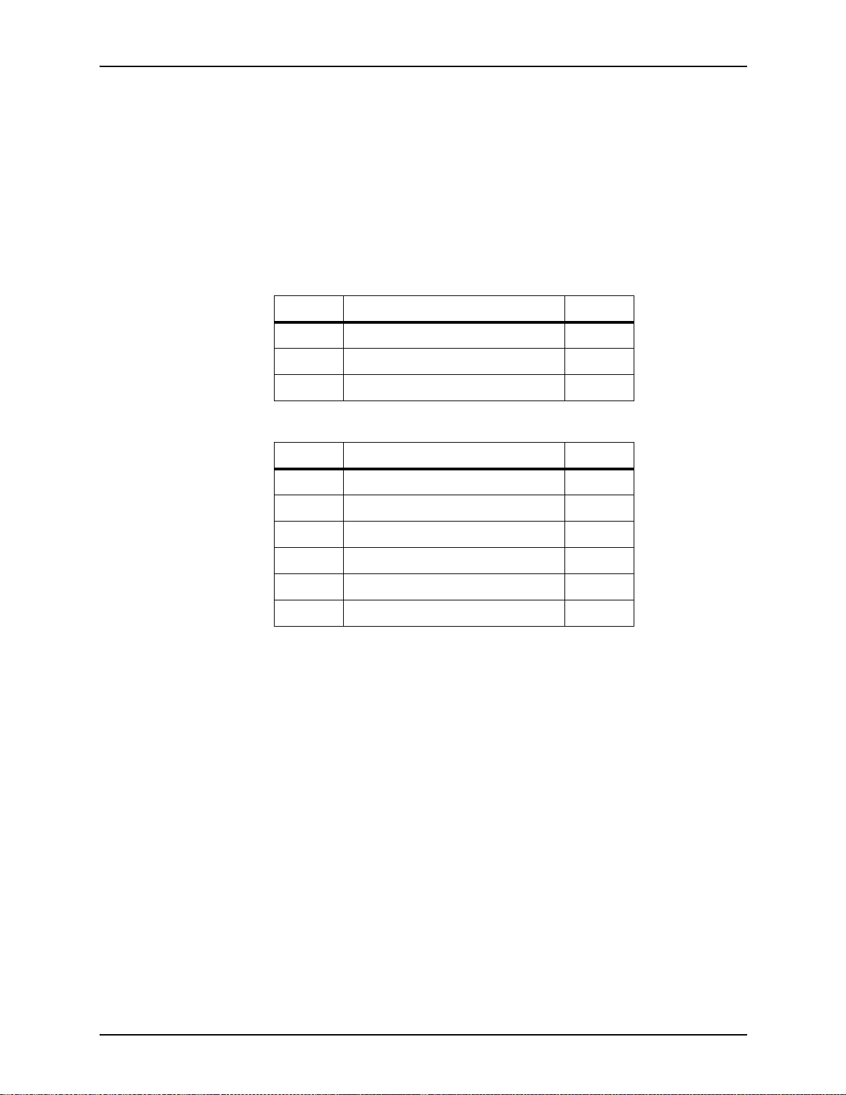
Supplies
The printer operat es in diff eren t pitch mo des. The pitch mode the
printer uses for a specific print job is based on the paper size on
which that job is printed. The following tables list the pitch mode
boundary values, paper widths, and related printing speeds
supported on the 96/4635/180 printer. These charts show that
the shorter the paper width, the higher the pitch mode and the
faster the throughput speed—higher pages per minute (p pm)
rate. (“Pages per minute” is synonymous with “impressions per
minute.”)
Table A-1. Throughput data: 96 printer
Pitch Paper width Speed
5 7.4 to 12.12 in. / 188 to 308 mm 96 ppm
4 12.12 to 15.31 in. / 308 to 389 mm 77 ppm
3 15.31 to 17 in. / 389 to 432 mm 58 ppm
Table A-2. Throughput data: 4635 printer
Pitch Paper width Speed
8 7 to 7.4 in. / 178 to 188 mm 154 ppm
7 7.4 to 9.01 in. / 188 to 229 mm 135 ppm
6 9.01 to 10.19 in. / 229 to 259 mm 116 ppm
5 10.19 to 12.12 in. / 259 to 308 mm 96 ppm
4 12.12 to 15.31 in. / 308 to 389 mm 77 ppm
3 15.31 to 17 in. / 389 to 432 mm 58 ppm
A-4 System Overview Guide
Page 77

Supplies
Table A-3. Throughput data: 180 printer
Pitch Paper width Speed
8 7 to 7.4 in. / 178 to 188 mm 206 ppm
7 7.4 to 9.01 in. / 188 to 229 mm 180 ppm
6 9.01 to 10.19 in. / 229 to 259 mm 154 ppm
5 10.19 to 12.12 in. / 259 to 308 mm 128 ppm
4 12.12 to 15.31 in. / 308 to 389 mm 103 ppm
3 15.31 to 17 in. / 389 to 432 mm 77 ppm
When the printing speed appears to degrade, you may be able to
improve it by running the print job in a higher pitch mode.
Paper size/pitch
mode minimum
and maximum
The illustrations in this section show the pitch modes in which
you can operate with the smallest and largest size papers
supported by the 96/4635/180 printer.
Using small paper sizes in 8-pitch mode:
Printing in 8-pitch mode provides the highest throughput speed
ava ila b le: up to 154 ppm f or th e 4635 prin ter an d up to 206 ppm
for the 180 printer. (The 96 printer does not support 8-pitch
mode.) However, you should keep the following in mind when
you select the paper you want to use for this mode:
• Paper sizes smaller than 8 inches / 203 mm are supported
only when the optional 7-inch paper kit is installed on the
printer.
• The leading edge of any paper used in the printer cannot be
less than 10 inch es / 254 mm long.
The follo wi ng figure illustr ates the ma ximu m and min imum pap er
sizes supported in 8-pitch mode.
System Overview Guide A-5
Page 78

Supplies
Figure A-1. 8-pitch mode paper sizes (4635 and 180 only)
1. Maximum paper size for 8 pitch mode
2. Minimum paper size for 8 pitch mode
3. Travel direction of sheets out of paper tray
Using large paper sizes in 3-pitch mode:
Large paper sizes—widths of 15.31 to 17 inches / 389 to 432
mm—are supported only in 3-pitch mode and must feed short
edge first. These paper sizes slow down the throughput speed
(as shown in tables above).
NOTE : The 96/4635/180 printer can support 14 by 17-i nch / 356
by 432 mm, 20 pound or 80 gsm paper stock in 3-pitch mode.
However, printing performance is n ot guaranteed for all types of
paper of this size. Heavy (110-pound / 200 gsm) and light (16pound / 60 gsm) large papers can cause jams throughout the
system and are not recommended.
The follo wi ng figure illustr ates the ma ximu m and min imum pap er
sizes supported in 3-pitch mode.
A-6 System Overview Guide
Page 79

Figure A-2. 3-pitch mode paper sizes
Supplies
Feed direction for
some standard
paper sizes
1. Maximum paper size for 3 pitch mode
2. Minimum paper size for 3 pitch mode
3. Travel direction of sheets out of paper tray
Currently, 14 inches / 356 mm is the maximum paper length
supported for long ed ge feeding (5 to 8 pitch mode). An y pa per s
with long edges g reater than this ( such as 11 b y 17 i nch / 2 79 b y
432 mm paper) must be loaded for short edge feeding (3 or 4
pitch mode).
The following figures illustrate how some of the supported
standard paper sizes, in various pitc h modes, feed through the
printer.
European papers:
The following diagrams show how A4 and A3 paper sizes feed
through the printer.
System Overview Guide A-7
Page 80

Supplies
Figure A-3. A4 (210 by 297 mm) paper feeding
(long edge feed)
Figure A-4. A3 (297 by 420 mm) paper feeding
(short edge feed)
US papers:
The following diagrams show how US Letter and US Ledger (or
US Tabloid) paper sizes feed through the printer.
Figure A-5. US Letter (8.5 by 11 inch) paper feeding
(long edge feed)
A-8 System Overview Guide
Page 81

Supplies
Figure A-6. US Ledger or US Tabloid (11 by 17 inch) paper
feeding (short edge feed)
B4 papers:
There are two sizes of B4 paper—European or ISO (9.84 by
13.89 inches / 250 by 353 mm) and Japanese or JIS B4 (14.33
by 10.12 inches / 364 by 257 mm). European B4 feeds long
edge first, while JIS B4 feeds either long edge or short edge first.
Figure A-7. B4 (250 by 353 mm) paper feeding
(long edge feed)
Figure A-8. JIS B4 (257 by 364 mm) paper feeding
(long edge feed and short edge feed)
System Overview Guide A-9
Page 82

Supplies
Paper care
Once you have purchased your paper , you must be sure it is
stored and conditioned properly, so th at it performs optimally in
the printer with a minimum of jams.
Storing paper Paper tends to curl under the heat that is present inside
xerographic equipment. To minimize the amount of curling, use
paper with low moisture content. Paper with excessive moisture
content has a tendency to jam because of the greater curl. The
maximum recommended moisture content is 5.7 percent.
Keep these points in mind when preparing your paper storage
area:
• Store paper in its own wrapper; do not leave it unwrapped or
where it can be damaged by dampness or heat.
• Store paper on a flat surface and not on its side or edge.
• Store reams of paper in a closed cabinet.
• Always store paper in a cool, dry area. Store on pallets or
shelves, not on the floor.
• Plan ahead and keep at least a day’s supply of paper in the
same area as the printer to allow environmental stabilization
prior to printing.
For more detailed information on paper for Xerox printers, refer
to Helpful Facts about Paper, provided with your printer.
A-10 System Overview Guide
Page 83

Supplies
Conditioning
paper
Figure A-9. Storing paper correctly
Figure A-10. Recommended temperature and humidity for
paper storage
Because temp erature and humidi ty affect paper performance in
the printer, you need to condit ion paper before using it. To do
this, store pap er f or a specif ied lengt h of tim e in the same type of
environment as your printer.
System Overview Guide A-11
Page 84

Supplies
The length of time you should condition your paper depends on
the amount of pap er a nd the dif f er ence bet ween the stor age a nd
operating temp eratures.
Use the foll owing ch art to determine the length of time needed to
condition stacked cartons of paper.
NOTE: The numbers in the top two rows indicate the
temperature difference between the storage area and the
operating environment, not actual room temperatures.
Table A-4. Paper conditioning: Recommended temperature
differences between storage and operating areas
Temperature differences between storage and
operating areas
Fahrenheit
o
10
Centigrade
o
5.5
Cartons Hours
14
55
10 8 14 18 22 27 38 51
20 11
40 14
o
15
o
8.5
8 1114172434
9 1215182535
16 23 28 35 48 67
19 26 32 38 54 75
20
11
o
o
25
13
o
o
30
17
o
o
40
22
o
o
50
28
o
o
Example: (See the shaded rows in the table above.) If you want
to move ten cartons of paper from a storage area with a
temperature of 90 oF to an operating area with a temperature of
75 oF (a 15o difference), you should do so at least 14 hours
before using the paper.
Other supplies
This section describes the supplies other than paper that are
necessary for installation and afterward. Your sales
representative will help you place your initial supply order.
A-12 System Overview Guide
Page 85

Supplies
Dry ink
Dry ink (also called toner) is the black powder which forms the
image on the printed page. There are three cartridges of dry ink
in each carton. You should keep at least one extra cartridge on
hand at all times. The disposable cartridges are easily changed
with no mess. The consumption rate of Xerox dry ink is
approximately one cartridge per 60,000 pages. Use only dry ink
that is specified for use in the 96, 4635, or 180 printer, as
described in the consumable supplies table.
MICR dry ink MICR d ry ink is the magnetic black powder which forms the
image on the printed MICR do cument. There are three cartridges
of MICR dry ink in each carton. The con sumption rate of Xerox
MICR dry ink is approximately one cartridge per 60,000 pages.
Use only MICR dry ink in your 96/4635/180 MICR printer.
The dry ink used with the 96/4635/180 MICR system is designed
for MICR printing and does not function well when used in nonMICR systems. The same proced ure used f or non-MICR printing
systems is used to add the dry ink to the 96/4635/180 MICR
printer.
Fuser agent
NOTE: Dry ink yields are based on 7% area coverage. Your
yield may vary, depending on coverage.
CAUTION
Use only MICR dry ink in the 96/4635/180 MICR printer. Do not
use standard dry ink. MICR dry ink cannot be reused.
Fuser agent (the lubricant for the printer fuser) is a consumable
item required by the 96/4635/180 printers. You should keep at
least two boxes on hand for installation by the service
representative. The consumption rate of Xerox fuser agent is
approximately one bottle per 250,000 pages. For product
information, refer to the consumable supplies table in this
appendix.
System Overview Guide A-13
Page 86

Supplies
Developer
Developer is not consumed by the printer but does have an
effective life of approximately 1,000,000 pages per carton
(600,000 per carton for MICR developer). Both kinds of
developer are guaranteed by Xerox for 600,000 pages per
carton. Developer is a required item and must be kept on hand.
Use only the developer specified for use in your 96, 4635,or 180
printer.
CAUTION
The 96/4635/180 MICR printers require a different developer,
with a different part number, from the developer used in the
standard 96/4635/180 printe r. Be sure you use only designated
MICR developer in the 96/4635/180 MICR printers.
The developer is changed by your service representative. For
product information, refer to the consumable supplies table in
this appendix.
Diskettes
Diskettes are optional items that provide loading and backup of
fonts, forms, and user files to and from the printing system. The
processor accepts 3.5-inch, 1.44 MB, double-sided, high density
diskettes.
Cartridge tapes
The optional 4 mm cartridge tape drive uses 5 GB or 8 GB tapes.
The optional quarter-inch cartridge (QIC) tape drive uses 150
MB QIC tapes.
Stacker containers and pallets
Stacker containers can be placed inside the stacker bins to
receive and neatly stack large amounts of output. These
containers are available in a variety of sizes, accommodating
various standard U. S. and international paper sizes. Different
sized pallets for containerless stacking can also be ordered.
A-14 System Overview Guide
Page 87

Supplies
Fonts
Data can be printed on DocuPrint printers in many sizes and
type styles called fonts. A font is a character set which has
unique characteristics, such as type style, size, weight,
orientation (portrait, landscape, inverse portrait, and inverse
landscape), character spacing (fixed and proportional), line
spacing, and postures (Roma n, it al ic, and so forth).
There are three classifications of fonts:
• Standard fonts
• Licensed fonts
• Custom fonts.
Standard fonts Provided with your printer’s operating system software is a
library of over 250 standard 300 dpi fonts, referred to as the A03
font family.
Standard fonts A library of 51 fonts is provided with your pr inter’s operating
system software.
Licensed fonts In addition to the library of standard fonts delivered with your
printer, over 100 licensed fonts may be ordered from the Xerox
Font Center.
Licensed fonts Additional fonts may be ordered from your local Xerox Font
Center.
Custom fonts Custom fonts and graphic images such as company logos and
signatures can be digitized by the Xerox Font Center for use on
your printer.
Receiving fonts Fonts are received on a diskette fro m your local Xerox Font
Center.
MICR tools
You can use the following tools to determine whether the MICR
output is printing within MICR specifi cations:
• MICR Positioning and Dimension Gauge.
• 8 Power (X) Comparator with MICR grid.
System Overview Guide A-15
Page 88

Supplies
NOTE: You should use the Cust om Transfer Assist Blade to
ensure acceptable MICR line quality on all MICR printing
systems that use nonstandard paper sizes.
MICR Positioning and Dimension Gauge
The MICR Positioning and Dimension Gauge (part number
600T80025) consists of a thin sh eet of fle xib le plastic atta ched to
the bottom of a piece of h ard thic k plastic. Th e gauge is pr ovi ded
in a kit that includes a small magnifying glass.
To use the gauge, place the printed output between the two
pieces of plastic. This allows you to compare the MICR output
elements against industry standard output. Using this process,
you can verify the character spacing, check the horizontal and
vertical alignment, and look for spots and voids.
MICR comparator
You use the eight power (X) comparator with MICR grid to
compare the cha racter s on t he MICR output to indu stry standard
output.
The comparator is an optical tool that magnifies each character
eight times. It has a built-in scale that measures the size of the
MICR characters and checks for spots and voids (deletions).
Keep the following in mind when using the 8 Power (X)
Comparator with MICR grid:
• Patterned paper can cause viewing problems. You should
use white paper when you perform quality evaluations.
• The quality of the MICR output may vary, depending on the
type of paper you use.
• Handle the comparator with care. The grid is printed on the
bottom and may be damaged or worn off in time.
You can use the comparator with transmitted or reflected light.
A-16 System Overview Guide
Page 89

Consumable supplies tables
A number of supplies are a v ailable from Xer ox f or you r DocuPrint
printer. Use the following tables to help determine your supply
needs.
NOTE: Customers in the U. S. may use the part numbers in
these tables to order supplies. Customers outside the U. S.
should contact their local service organization for part numbers.
Paper and special stocks tables
The following tabl es li st all thr o ugh pu t sto cks available for the 96/
4635/180 printers, with size, order number, and a brief
description for each.
Supplies
Table A-5. Stocks list for 96/4635/180 printers
Item Description Part number
Paper Xerox paper quantities are 10 reams (5,000 sheets) to a carton
unless otherwise noted below.
8.5 x 11 inch 4024 Dual Purpose Paper 3R721
A4 4024 Dual Purpose Paper 3R2594
8.5 x 14 inch 4024 Dual Purpose Paper 3R727
8.5 x 11 inch 4024 Dual Purpose Paper, 3-hole 3R723
8.5 x 11 inch 4024 Dual Purpose Paper, 3-hole* 3R2193
8.5 x 11 inch 4024 Dual Purpose Paper, 4-hole 3R1983
8.5 x 11 inch 4024 Dual Purpose Paper, 4-hole* 3R3008
8.5 x 11 inch 4024 Dual Purpose Paper, 7-hole 3R1984
8.5 x 11 inch 4024 Dual Purpose Paper, 7-hole* 3R3010
8.5 x 11 inch 4024 Smooth 3R2675
8.5 x 14 inch 4024 Smooth 3R2677
8.5 x 11 inch 4200 Dual Purpose Paper 3R2047
8.5 x 14 inch 4200 Dual Purpose Paper 3R2051
8.5 x 11 inch 4200 Dual Purpose Paper, 3-hole 3R2641
8.5 x 11 inch 4200 Dual Purpose Paper, 4-hole 3R3012
* 5/16-inch drilled holes
** Rainbow pack contains 750 sheets each of blue and yellow, 500 sheets each of green
and pink, and 250 sheets each of buff, gray, goldenrod, and ivory.
System Overview Guide A-17
Page 90

Supplies
Table A-5. Stocks list for 96/4635/180 printers (Continued)
Item Description Part number
8.5 x 11 inch 4200 Dual Purpose Paper, 7-hole 3R3014
8.5 x 11 inch Dual Purpose Colors—Blue 3R3052
8.5 x 11 inch Dual Purpose Colors—Blue, 3-hole 3R3068
8.5 x 14 inch Dual Purpose Colors—Blue, 3-hole 3R3084
8.5 x 11 inch Dual Purpose Colors—Green 3R3056
8.5 x 11 inch Dual Purpose Colors—Green, 3-hole 3R3072
8.5 x 14 inch Dual Purpose Colors—Green 3R3088
8.5 x 11 inch Dual Purpose Colors—Pink 3R3058
8.5 x 11 inch Dual Purpose Colors—Pink, 3-hole 3R3074
8.5 x 14 inch Dual Purpose Colors—Pink 3R3090
8.5 x 11 inch Dual Purpose Colors—Yellow 3R3054
8.5 x 11 inch Dual Purpose Colors—Yellow, 3-hole 3R3070
8.5 x 14 inch Dual Purpose Colors—Yellow 3R3086
8.5 x 11 inch Dual Purpose Colors—Buff 3R3060
8.5 x 11 inch Dual Purpose Colors—Buff, 3-hole 3R3076
8.5 x 14 inch Dual Purpose Colors—Buff 3R3092
8.5 x 11 inch Dual Purpose Colors—Goldenrod 3R3062
8.5 x 11 inch Dual Purpose Colors—Goldenrod, 3-hole 3R3078
8.5 x 14 inch Dual Purpose Colors—Goldenrod 3R3094
8.5 x 11 inch Dual Purpose Colors—Ivory 3R3064
8.5 x 11 inch Dual Purpose Colors—Ivory, 3-hole 3R3080
8.5 x 14 inch Dual Purpose Colors—Ivory 3R3096
8.5 x 11 inch Dual Purpose Colors—Gray 3R3066
8.5 x 11 inch Dual Purpose Colors—Gray, 3-hole 3R3802
8.5 x 14 inch Dual Purpose Colors—Gray 3R3098
8.5 x 11 inch** Dual Purpose Colors, Rainbow Pack—35,000
sheets per carton**
8.5 x 11 inch 10 Series Dual Purpose Paper 3R2950
3R3107
8.5 x 11 inch 10 Series Dual Purpose Paper, 3-hole 3R2952
8.5 x 11 inch 10 Series Dual Purpose Paper, 3-hole* 3R3016
* 5/16-inch drilled holes
** Rainbow pack contains 750 sheets each of blue and yellow, 500 sheets each of green
and pink, and 250 sheets each of buff, gray, goldenrod, and ivory.
A-18 System Overview Guide
Page 91

Supplies
Table A-5. Stocks list for 96/4635/180 printers (Continued)
Item Description Part number
8.5 x 14 inch 10 Series Dual Purpose Paper 3R2954
8.5 x 11 inch 10 Series Smooth 3R54
8.5 x 14 inch 10 Series Smooth 3R83
8.5 x 11 inch 4024 Dual Purpose, reinforced 3-hole* 3R2057
A3 4024 Dual Purpose paper 3R91721
A3 4024 Dual Purpose paper 3R2594
9.5 x 11 inch 65-pound divider white
2,500 sheets per carton
11 x 17 inch 4024 Dual Purpose Paper
2500 sheets per cartons
11 x 17 inch 4024 Dual Purpose Paper, 7-hole*
2500 sheets per cartons
Transparencies Xerox transparencies are packaged 100 sheets to a box.
8.5 x 11 inch Clear, with a white strip on the edge 3R2780
8.5 x 11 inch Clear, with removable strip 3R3108
8.5 x 11 inch Clear, high speed, with paper backing 3R3028
Labels (gummed) Xerox labels are packaged 100 sheets to a box.
8.5 x 11 inch 33 labels per sheet 3R3139
8.5 x 11 inch 6 labels per sheet 3R3146
8.5 x 11 inch Custom form (uncut) Contact Xerox
8.5 x 11 inch 1-up label 3R4476
8.5 x 11 inch 1-up label 3R4475
3R3428
3R729
3R3074
Supplies Order
Service
8.5 x 11 inch 1-up label 3R4474
* 5/16-inch drilled holes
** Rainbow pack contains 750 sheets each of blue and yellow, 500 sheets each of green
and pink, and 250 sheets each of buff, gray, goldenrod, and ivory.
System Overview Guide A-19
Page 92
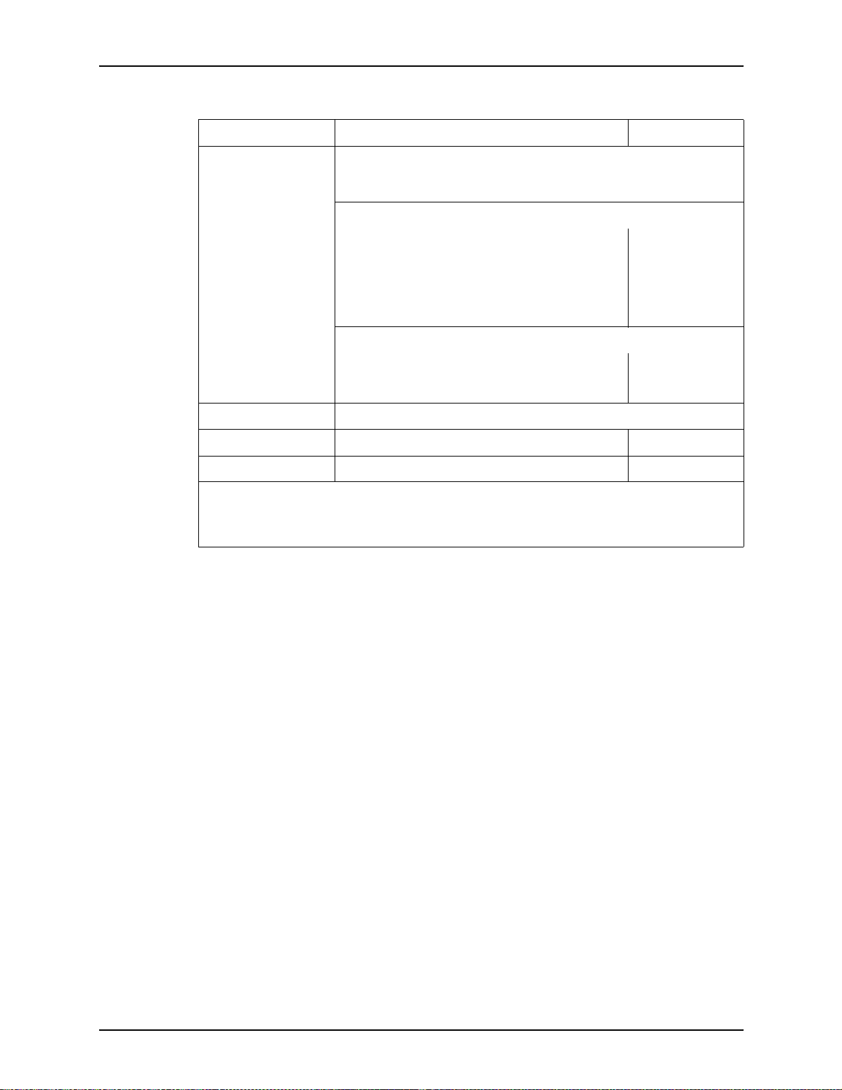
Supplies
Table A-5. Stocks list for 96/4635/180 printers (Continued)
Item Description Part number
Tab stock Xerox tab stock is packaged in 5-tab sets. 250 sheets per carton.
Straight collated singles (forward, top down):
• Non-drilled 90-pound, Index white
• Non-drilled 90-pound, blue
• Three-hole 90-pound, Index white
• Three-hole 90-pound, blue
Reverse collated singles (bottom up):
• Non-drilled 90-pound, Index white
• Three-hole 90-pound, Index white
Cover stock Xerox cover stock is packaged 2,500 sheets per carton.
8.5" x 11" 65-pound, blue 3R3044
8.5" x 11" 65-pound, white 3R3041
* 5/16-inch drilled holes
** Rainbow pack contains 750 sheets each of blue and yellow, 500 sheets each of green
and pink, and 250 sheets each of buff, gray, goldenrod, and ivory.
3R4417
3R4425
3R4418
3R4426
3R4415
3R4416
A-20 System Overview Guide
Page 93

Table A-6. Carbonless stocks for 96/4635/180 printers
Supplies
Size Parts Sequence Sheets
8.5 in. x 11 in. *2
2
2
3
3
Reverse/
Straight
Straight/
Double
Reverse/
Straight
Straight
Straight/
Double
Alternating
CB-White
CF-Canary
Alternating
CB-White
CB-White
CF-Canary
CF-Canary
Alternating
CB-White
CF-Pink
Alternating
CB-White
CFB-Canary
Alternating
CB-White
CB-White
CFB-Canary
CFB-Canary
CF-Pink
CF-Pink
Sheets per
carton
5000
5000
5000
5010
5010
Sets per
carton
2500
2500
2500
1670
1670
Cartons
per pallet
40
40
40
40
40
Part
number
3R4225
3R4226
3R4227
3R4230
3R4231
4
N/A
N/A
N/A
N/A
N/A
N/A
N/A
N/A
* All papers are packaged 500 sheets per ream, with 10 reams per carton. Each ream contains only
complete
carbonless sets (that is, 501 sheets in a three-part ream for 167 sets).
Straight
N/A
N/A
N/A
N/A
N/A
N/A
N/A
N/A
Alternating
CB-White
CFB-Canary
CFB-Pink
CF-Goldenrod
CB-White
CFB-White
CFB-Canary
CFB-Pink
CF-White
CF-Canary
CF-Pink
CF-Goldenrod
5000
5000
5000
5000
5000
5000
5000
5000
5000
1250
N/A
N/A
N/A
N/A
N/A
N/A
N/A
N/A
40
40
40
40
40
40
40
40
40
3R4235
3R4236
3R4238
3R4239
3R4240
3R4242
3R4243
3R4244
3R4245
System Overview Guide A-21
Page 94

Supplies
Table A-6. Carbonless stocks for 96/4635/180 printers (Continued)
Sheets per
Size Parts Sequence Sheets
8.5 in. x 14 in.* 2
3
N/A
N/A
N/A
N/A
* All papers are packaged 500 sheets per ream, with 10 reams per carton. Each ream contains only
complete
carbonless sets (that is, 501 sheets in a three-part ream for 167 sets).
Reverse/
Straight
Straight
N/A
N/A
N/A
N/A
Alternating
CB-White
CF-Canary
Alternating
CB-White
CFB-Canary
CF-Pink
CB-White
CFB-Canary
CF-Canary
CF-Pink
carton
5000
5010
5000
5000
5000
5000
Sets per
carton
2500
1670
N/A
N/A
N/A
N/A
Cartons
per pallet
30
30
30
30
30
30
Part
number
3R4228
3R4233
3R4237
3R4241
3R4246
3R4247
Complete supplies list—96/4635/180 printers
The following table lists the supplies in addition to paper th at a r e
available for your printer. Use this table to help you determine
your supplies needs.
Table A-7. Complete supplies list for 96/4635/180
Item Description Part number
Dry ink Consumption rate is approximately
one cartridge per 60,000 pages.
Dry ink, MICR Packaged 3 cartridges per carton.
Consumption rate is approximately
one cartridge per 60,000 pages.
Dry ink waste
bottle
Developer Packaged 2 bottles per carton.
Effective life is approximately one
carton per 1,000,000 pages.
(2 bottles required for
replacement.)
6R206 3/carton 180,000 pages/carton
6R819 3/carton 180,000 pages/carton
93K460
5R161 2/car ton 1,000,000 pages/
Items/
carton Expected yield / carton
NOTE: Dry ink (toner)
yields are based on 7%
area coverage. Your
yield may vary,
depending on
coverage.
carton
A-22 System Overview Guide
Page 95

Table A-7. Complete supplies list for 96/4635/180 (Continued)
Item Description Part number
Supplies
Items/
carton Expected yield / carton
Developer,
MICR
Fuser agent Packaged 1 bottle per carton.
Cleaning
supplies
Diskettes 3.5-inch, 1.44 MB, double-sided,
Cartridge tapes 1/4-inch (26-track) blank cartridge
Packaged 2 bottles per carton.
Effective life is approximately one
carton per 600,000 pages.
(2 bottles required for
replacement.)
Consumption rate is approximately
one bottle per 250,000 pages.
Foam-tipped swabs 99P87256
Lint-free towels 35P2163
Magnetic head cleaning kit.
Packaged 2 diskettes per box.
1/4-inch cartridge head cleaning kit 9R88432
Hub and Transport Cleaner 99P87486
4 mm cartridge drive head cleaning
kit
high density diskettes. Packaged
10 diskettes per box.
tape (QIC), 150MB
4mm blank cartridge tape, 5GB
4mm blank cartridge tape, 8GB
5R573 2/carton 600,000 pages/carton
8R2955 1/carton 250,000 pages/bottle
8R3811
9R01189
8R7683 10/box
9R84168
9R01190
109R00314
Ordering supplies
To avoid unnecessary downtime, always have an adequate
amount of the necessary supplies. To do this, you need to
establish a procedure for checking and ord ering supp lies. A
supplies checklist is provided at the end of this chapter to help
you with this task. It lists the supplies needed for the printer and
contains a column for you to enter the date when you want to
place the order and a column to record the date of the actual
order. The consumable supplies table, above, contains a list of
Xerox supplies available for the printer.
It is important that you check your supplies regularly and order
before you run out. Plan on approximately five working days for
delivery after placing the order. You can make arrangements to
receive them sooner in emergency situ ations.
System Overview Guide A-23
Page 96

Supplies
Your Xerox sales representative can help you submit the initial
order of supplies needed for installation. These items include
paper, dry ink, MICR dry ink, fuser agent, developer, and MICR
developer.
Once your printer volume is established, planning ahead and
buying Xerox supplies in quantity can save you money. Your
Xerox supply specialists can help you. There are two centers
available to assist you:
• To order Xerox paper, transparencies, labels, dry ink, MICR
dry ink, developer, MICR developer, fuser agent, cartridge
tapes, and diskettes, call the Xerox Supply Ce nter at 1-800822-2200, weekdays between 7:30 a.m. and 6:00 p.m.,
Pacific time.
If you prefer, you may mail orders to the following address:
Xerox Corporation
P. O. Box 250 75
Santa Ana, CA 92799-5075
• To order cleaning supplies, call the Xerox Customer Parts
and Product Support Center at 1-800-828-5881, weekdays
between 5:30 a.m. and 5:00 p.m., Pacific time, (U.S. only).
You may also mail cleaning supply orders to the following
address:
Xerox Corporation
Parts Marketing Center
Building 214-07S
P. O. Box 102 0
Webster, NY 14580
Please provide the following information when placing orders:
• Your customer number (provided by you r Xerox sales
representative)
• Your printer model
• Your supply order, including the following information:
– Item name
–Part number
– Quantity desire d
– If your co mpan y r equir es a pu rchase orde r for payment of
an invoice, you need to provide the purchase order
number to Xerox at the time you place the order.
A-24 System Overview Guide
Page 97

Supplies
Supplies checklist
The following table is a checklist that you can use to keep track
of the supplies you order. Use this checklist to help record the
supplies you require, the date on which the order should be
placed, and the actual date of the order.
Table A-8. Supplies checklist for 96/4635/180 printer
Item Description and part number Quantity Date to order Date ordered
Paper
Transparencies
Labels
Dry ink
MICR dry ink
Developer
MICR developer
System Overview Guide A-25
Page 98

Supplies
Table A-8. Supplies checklist for 96/4635/180 printer (Continued)
Item Description and part number Quantity Date to order Date ordered
Fuser agent
Floppy disks
Cleaning supplies
A-26 System Overview Guide
Page 99

B. Paper performance guidelines
The following guides summarize the capabilities of the paper
trays, duplex printing considera tions, and paper stock
considerations.
Table B-1. Trays 1 and 2 performance guide
Paper Superior performance Good performance
Performance limits and
suggested alternatives
Size
a
range
Weight
range
Capacity Tray 1: 1100 sheets, 20
Type or
condition
8 by 10 to 9 by 14 inches /
203 by 254 to 229 by 356
mm. Includes:
• 8.5 by 11 inches
• A4 (210 by 297 mm)
20 to 110 pounds / 80 to
200 gsm
pound or 80 gsm paper
Tray 2: 600 sheets, 20
pound or 80 gsm paper
• Xerographic paper in
good condition
• Predrilled stock (fanned
thoroughly)
• Tab stock (in per fectly
flat condition)
16 to 20 pounds/60 to 80
b
gsm
• Transparencies
• High-speed label stock
• Slightly curled paper
• Intermixed weights
• Paper with reinforced
binding edges
c
Paper smaller than 8 by 10
inches / 203 by 254 mm
cannot be used.
For paper larger than 9 by
14 inches / 229 by 356 mm,
refer to “Performance Guide
for trays 3, 4, 5 and 6.”
Weights outside t he limits
shown are not
recommended.
Refer to the “Paper Stocks
guide,” later in this chapter,
for additional information.
For greater capacity, use
trays 3, 4, 5 and 6 and the
Autoswitch feature.
• Excessively curled
d
paper
• Manual two-sided
(duplex) prints
• Freshly printed offset
prints
a. Optional 7 X 10 enablement kit allows 7 by 10 inches / 178 by 254 mm paper size.
b. Make sure that heavy weight paper levers (located in areas 2 and 4 of the printer) are in the
appropriate position for the weight of paper being used.
c. Curl direction should be determined before loading paper into trays. For additional information,
refer to the “Clearing paper misfeeds and jams” chapter in your Troubleshooting Guide.
d. Curl direction should be determined before loading paper into trays. For additional information,
refer to the “Clearing paper misfeeds and jams” chapter in your Troubleshooting Guide.
System Overview Guide B-1
Page 100

Paper performance guidelines
Table B-2. Trays 3, 4, 5 and 6 (or high capacity trays) performance guide
Paper Superior performance Good performance
Performance limits and
suggested alternatives
Size
range
a
8 by 10 to 11.69 by 17
inches / 203 by 254 to 297
by 432 mm. Includes:
• 11 by 14 inches
• 11 by 17 inches
• B4 (250 by 353 mm)
• A3 (297 by 420 mm)
Weight
range
20 to 110 pounds / 80 to
200 gsm
Capacity Tray 3: 2600 sheets, 20
pound / 80 gsm paper
Tray 4: 2600 sheets, 20
pound/80 gsm paper
Type or
condition
• Xerographic paper in
good condition
• Predrilled stock (fanned
thoroughly)
16 to 20 pounds/60 to 80
b
gsm
• Slightly curled paper
c
• Manual two-sided
(duplex) prints
• High speed label stock
Smaller or larger sizes
cannot be used.
Weights outside t he limits
shown are not
recommended.
For greater capacity , use the
Autoswitch feature.
• Excessively curled
d
paper
• Curl direction should be
determined before
loading paper into tray.
e
• DO NOT use mylar
reinforced paper in trays
3, 4, 5 or 6. Hardware
damage may result.
Use trays 1 or 2.
a. Optional 7 by 10-inch enablement kit allows 7 by 10 inches / 178 by 254 mm paper size.
b. Make sure that heavy weight paper levers (located in areas 2 and 4 of the printer) are in the
appropriate position for the weight of paper being used.
c. Curl direction should be determined before loading paper into trays. For additional information,
refer to the “Clearing paper misfeeds and jams” chapter in your Troubleshooting Guide.
d. Curl direction should be determined before loading paper into trays. For additional information,
refer to the “Clearing paper misfeeds and jams” chapter in your Troubleshooting Guide.
e. Curl direction should be determined before loading paper into trays. For additional information,
refer to the “Clearing paper misfeeds and jams” chapter in your Troubleshooting Guide.
B-2 System Overview Guide
 Loading...