

Page 1

Xerox DocuPrint 96/DocuPrint 96MX
Laser Printing System
Operations Reference
April 1998
721P85610
Page 2

Xerox Corporation
701 S. Aviation Boulevard
El Segundo, CA 90245
©1998 by Xerox Corporation. All rights reserved.
Copyright protection claimed includes all forms and matters of
copyrightable material and information now allowed by statutory or
judicial law or hereinafter granted, including without limitation,
material generated from the software programs which are displayed
on the screen, such as icons, screen displays, looks, etc.
Printed in the United States of America.
Publication number: 721P85610
Xerox® and all Xerox products mentioned in this publication are
trademarks of Xerox Corporation. Products and trademarks of other
companies are also acknowledged.
Changes are periodically made to this document. Changes, technical
inaccuracies, and typographic errors will be corrected in subsequent
editions.
This document was created on a PC using Frame software. The
typeface used is Helvetica.
Page 3

Relate d pu blicatio ns
The
Xerox DocuPrint 96/DocuPrint 96MX Laser Printing System
Operations Reference
your laser printing system. The entire reference set is listed in the
table below. Several other related documents are also listed for your
convenience. For a complete list and description of available Xerox
documentation, refer to the Xerox Documentation Catalog
(Publication number 610P17417) or call the Xerox Documentation
and Software Services (XDSS) at 1-800-327-9753.
Table 1. Related P ubl i ca tio ns
Publicat io n Number
is part of the eight manual reference set for
Xerox DocuPrint 96/DocuPrint 96MX Laser Printing
System Operator Guide
Xerox DocuPrint 96/DocuPrint 96MX Laser Printing
System Operations Reference
Xerox DocuPrint 96/DocuPrint 96MX Laser Printing
System Message Guide
Xerox DocuPrint 96/DocuPrint 96MX Laser Printing
System PDL Reference
Xerox DocuPrint 96/DocuPrint 96MX Laser Printing
System Forms Creation Guide
Xerox DocuPrint 96/DocuPrint 96MX Laser Printing
System System Generation Guide
Xerox DocuPrint 96/DocuPrint 96MX Laser Printing
System Installation Planning Guide
Xerox DocuPrint 96/DocuPrint 96MX Laser Printing
Operator Command Summary Card
Xerox Laser Printing Systems Tape Formats Manual
X
erox Laser Printing Systems Standard Font Library
Font User Guide
Helpful Facts About Paper
721P85590
721P85610
721P85650
721P85640
721P85630
721P85620
721P85600
721P85660
600P86175
600P86174
721P82492
Notice
This publication may contain descriptions of concepts and features
not currently available for your Xerox Laser Printing System. Consult
your Xerox sales represent ative or your operating system software
program description for additional information.
XEROX DOCUPRINT 96/DOCUPRINT 96MX LPS OPERATIONS REFERENCE iii
Page 4

iv XEROX DOCUPRINT 96/DOCUPRINT 96MX LPS OPERATIONS REFERENCE
Page 5

Table of Contents
Related publications iii
Notice iii
Introduction xxiii
About the reference set xxiii
DocuPrint 96/DocuPrint 96MX Laser Printing System document set xxiii
Who should use this manual xxv
LPS system administrators, programmers, operators xxv
How to use this manual xxvi
If the LPS is new to you xxvi
Know the key terms and conventions xxvi
Use the table of contents, index, and glossary xxvi
Refer to the related publications list xxvi
Key terms and conventions xxvii
Key terms xxvii
Syntax conventions xxvii
Masking conventions xxvii
Contents of this manual xxviii
Statement command summaries and appendices xxix
About the DocuPrint 96/DocuPrint 96MX LPS xxx
DocuPrint 96/DocuPrint 96MX system controller components xxxi
DocuPrint 96/DocuPrint 96MX tape and cartridge devices xxxii
DocuPrint 96/DocuPrint 96MX printer components xxxiii
1. Setting LPS parameters 1-1
Communicating with the LPS 1-1
Installation and system generation 1-3
User interface keyboard display 1-3
Powering on and booting the LPS 1-4
Power loss 1-5
System verification messages 1-6
Printer communication link 1-8
PSC (printer subsystem controller) 1-10
Configure a finishing or feeding device 1-11
Create the FCG.LIB file 1-11
FCG (display the profile labels) 1-15
FCG (configure a finishing or feeding device) 1-16
XEROX DOCUPRINT 96/DOCUPRINT 96MX LPS OPERATIONS REFERENCE v
Page 6

TABLE OF CONTENTS
FCG SHOW (check finishing or feeding device settings) 1-16
FCG procedures 1-17
Verifying LPS status 1-18
Verifying system version and time 1-18
OCS (system version display) 1-18
Time and date displays 1-18
Verifying syst em status 1-20
PROBLEM 1-20
Setting LPS parameters 1-22
Setting system parameters 1-22
SETTIME (set time or date) 1-22
ALIGN (set page print alignment) 1-23
DISPLAY (set display format for messages) 1-24
ENERGY 1-25
MICR (set MICR mode) 1-26
Setting parameters for print jobs 1-27
Reallocating space to the print file 1-27
REA (reallocate print fil e) 1-27
REA and disk management 1-30
REA and online report spooling 1-30
Setting job parameters 1-31
FONTS 1-31
FORMS 1-32
GRAPHIC 1-32
Adjusting print image darkness 1-33
DARKNESS 1-33
Lightening high-density images 1-34
EDGE 1-34
Finishing Exercise r Ut ilit y 1-34
FEX 1 -3 4
Setting file access and task execution privileges 1-36
Protecting access to files 1-36
LOGON (restrict file access) 1-36
SECURE (restrict file access) 1-37
Secured files, access, and manipulation 1-38
Security breach 1-38
Limiting task execution privileges 1-39
RCU (restrict command usage) 1-39
Tracking console activity with Data Capture Utility (DCU) 1-42
DCU CAPTURE 1-42
vi XEROX DOCUPRINT 96/DOCUPRINT 96MX LPS OPERATIONS REFERENCE
Page 7

TABLE OF CONTENTS
DCU DELETE 1-43
DCU EXIT 1-43
DCU FORMAT DISPLAY 1-44
DCU FORMAT PRINT 1-45
DCU HELP 1-46
DCU REMINDER 1-46
DCU RESET 1-46
DCU SHOW 1-47
Limitation during SYSGEN 1-47
Comment capability 1-47
2. Managing LPS resources 2-1
Maintaining optimal disk usage 2-1
Files on system disks 2-1
Operating on system files 2-1
Necessary free space on system disks 2-3
File biasing by disk configuration 2-4
Checking usage of disk space 2-6
FCHECK (file check) 2-6
Reorganizing usage of disk space 2-9
COMPRESS 2-9
PURGE 2-11
Backing up and copying system files 2-12
Setting default tape device 2-12
Identif y c ur r e nt TAPE & CARTRIDGE device (SUB DEV) 2-12
SUBSTITUTE DEVICE (general information) 2-12
Assign a controller device to TAPE or CARTRIDGE (SUB
DEV) 2-14
Know the Xerox tape and cartridge format 2-15
Prepare the tape or cartridge 2-16
TAPE [CARTRIDG E | TDn] VOLINIT 2-16
Copying files 2-17
COPY (disk to disk) 2-17
COPY (disk to labeled tape or cartridge) 2-18
COPY (disk to unlabeled tape) 2-19
COPY (labeled tape or cartridge to disk) 2-20
COPY (unlabeled tape to disk) 2-22
Manipulating files 2-23
DELETE 2-23
FID (build fi le lis t) 2- 2 4
FILE (display file list) 2-24
XEROX DOCUPRINT 96/DOCUPRINT 96MX LPS OPERATIONS REFERENCE vii
Page 8

TABLE OF CONTENTS
FIX (modify font or logo file) 2-28
REVIEW (review files) 2-29
RNAME (rename a file or directory) 2-29
TYPE 2-29
List tape or cartridge files 2-31
TAPE [CARTRIDG E | TDn] LIST 2-31
Locate tape or cartridge files 2-33
TAPE [CARTRIDG E | TDn] FIND (find file) 2-33
TAPE [CARTRIDG E | TDn] N E X T (move to ne xt file) 2-3 3
TAPE [CARTRIDG E | TDn] SKIP (move to 1st or 2nd... file)
2-34
TAPE [CARTRIDG E | TDn] EOF or NOEOF or ENDFILE 2-35
Backing up system files to tape or cart ri dge 2-37
DSR (disk save and restore) 2-37
Starting DSR 2-37
File protection 2-39
Disk space for restore 2-39
Multivolume files 2-40
Device error handling 2-40
Aborting the save process 2-40
Incomplete resto ration 2-40
Aborting the restore process 2-41
Special file handling 2-41
Copying a DSR file to the LPS 2-42
SFT (single file transfer ut ilit y ) 2-42
Managing files on floppy disks 2-45
FLOPPY FORMAT 2-45
FLOPPY SAVE 2-46
FLOPPY DELETE 2-47
FLOPPY C LE AR 2-48
FLOPPY FILE 2-48
FLOPPY FCHECK 2-50
FLOP PY REST O R E 2-51
FLOPPY LIST 2-52
Copying the system software tape 2-53
SST (system software tape or cartridge) 2-53
3. Tracking system activity 3-1
Accounting data in the status file 3-1
How the system adds data to the status file 3-1
Status file creation during sysgen 3-2
viii XEROX DOCUPRINT 96/DOCUPRINT 96MX LPS OPERATIONS REFERENCE
Page 9

TABLE OF CONTENTS
Backing up status file information 3-2
Status file data in the online accounting page 3-4
Status file data 3-5
DATE entry 3-5
DEPARTMENT entry 3-5
JOB ID entry 3-5
REPORT NO. entry 3-5
FILE ID entry 3-5
INPUT PROCESSING TIME entry 3-5
OUTPUT PROCESSING TIME entry 3-5
Report completion codes 3-6
PAGES TO BIN entry 3-7
PAGES TO TRAY entry 3-7
PAPER PATH HOLES entry 3-7
GRAPHIC PAGES PRINTED entry 3-7
LINES PRINTED entry 3-8
GRAPHIC EXCEPTION CODE entry 3-8
ONLINE IDLE (SEC) entry 3-8
TAPE MOUNTS entr y 3-8
BLOCKS READ entry 3 -8
BLOCKS SKIPPED entry 3-8
RECORDS READ entry 3-8
DJDE RECORDS READ entry 3-8
MAXIMUM COPY COUNT entry 3-8
OVERPRINTS entry 3-8
COLLATE entry 3-9
SF/MF entry 3-9
SIMPLEX/DUPLEX entry 3-9
JDE , JDL USE D entry 3-9
ACCTINFO entry 3-9
INITIAL FONT LIST entry 3-9
INITIAL FORM LIST entry 3-9
INITIAL CME LIST entry 3-10
Using accounting and system activity commands 3-11
Generating system activity reports 3-11
REPORT 3-11
Establishing accounts and copying account data to tape 3-16
ACCOUNT 3-16
Tape format of data written by ACCOUNT 3-18
Modifying the status file 3-21
XEROX DOCUPRINT 96/DOCUPRINT 96MX LPS OPERATIONS REFERENCE ix
Page 10

TABLE OF CONTENTS
SFS (status file services) 3-21
SFS CLEAR 3-22
SFS CREATE 3-23
SFS DISPLAY 3-24
SFS file- name 3-26
SFS HARDCOPY 3-27
SFS HOST 3-29
SFS TAPE 3-30
SFS TDn 3-31
SFS ? 3-31
SFS ! 3-31
Creating the SFS user form file 3-32
Tape format of data written by SFS 3-34
Structure of an SFS report entry 3-36
Forward and backward pointers 3-38
Dumping the status file to tape 3-38
XPS 3-39
4. Editing source files 4-1
What the editor is 4-1
How the editor works 4 -1
Source files 4-1
Viewing source files 4-1
Storing source files 4-2
Files you can edit 4-2
Edi tor comman ds 4-4
Three types of editor commands 4-4
Composite editor commands 4-4
Editor syntax conventions 4-5
Using the <TAB> key 4-6
Sta ck pri nting 4-6
Running an editing session 4-6
EDIT 4-6
CONVERT 4-7
NOCONVERT 4-7
GET 4-8
KEYS 4-8
MERGE 4-9
SAVE 4-9
CLEAR 4-10
x XEROX DOCUPRINT 96/DOCUPRINT 96MX LPS OPERATIONS REFERENCE
Page 11

TABLE OF CONTENTS
END 4-10
Modifying records 4-11
DISPLAY (display lines) 4-11
DUPLICATE (copy lines) 4-12
FIND (find lines with match) 4-12
INSERT (insert lines) 4-13
MODIFY (modify lines) 4-14
MOVE (move lines) 4-14
PRINT (print lines) 4-15
REMOVE (delete lines) 4-16
RENUMBER (renumber lines) 4-16
REPLACE (substitute lines) 4-17
SORT (sort lines) 4-17
STEP (display next line) 4-18
Modifying parts of records 4-19
C (change string) 4-19
D (delete string) 4-20
P (insert prior) 4-21
F (insert following) 4-21
O (overlay string) 4-22
S (substitute string) 4-23
Examples of editor sessions 4-24
Create and save a .JSL file 4-24
Modify and resave the.JSL file 4-25
List other .JSL files and insert one into the .JSL file 4-26
5. Using command files 5-1
Command files 5-1
System, editor, and font editor command files 5-1
Using system command files 5-2
Operator entries during execution 5-2
Error processing 5-2
.PAUSE processing 5-2
.WAIT processing 5-3
Using editor command files 5-4
Points to note 5-4
Using font editor command files 5-4
Verifying command file type 5-5
.BCP 5-5
Commands in command files 5-6
XEROX DOCUPRINT 96/DOCUPRINT 96MX LPS OPERATIONS REFERENCE xi
Page 12

TABLE OF CONTENTS
Displaying messages 5-6
Documenting the command file 5-6
Summary table of command file commands 5-7
Using the basic command file commands 5-8
.CHAIN 5-8
.DELAY 5-8
.EXIT 5-8
.HOME 5-9
.PAUSE 5-9
.WAIT 5-9
Using the logical processing command file commands 5-10
Using symbol setting commands 5-10
Using string substitution commands 5-11
Using sequence control commands 5-12
Using debugging commands 5-12
Sample command files 5-13
Editor command file to delete files 5-13
Sample verification of command file type 5-14
6. Editing font files 6-1
About the font editor 6-1
Reference documentation for fonts 6-1
Font editor 6-1
How to use the font editor 6-2
Summary table of font editor commands 6-3
Running a font editing session 6-4
Messages during the session 6-4
Starting a font editor session 6-4
Reordering a font file 6-5
REORDER and FEDIT 6-5
Specifying the primary source font file 6-5
FEDIT 6-5
INPUT 6-6
Selecting characters using the correct mode 6-7
Specifying new font file characters 6-8
INCLUDE 6-8
SUBSTITUTE 6-9
RECODE 6-9
Using a secondary source font file 6-10
OPEN 6-10
CLOSE 6-11
xii XEROX DOCUPRINT 96/DOCUPRINT 96MX LPS OPERATIONS REFERENCE
Page 13

TABLE OF CONTENTS
Closing font file without using CLOSE 6-12
Saving font files you create 6-12
OUTPUT 6-12
Ending the font editing session 6-13
END 6-13
7. LPS print processing 7-1
Overview 7-1
Laser printing systems (LPS) 7-2
LPS component types 7-2
LPS hardware components 7-2
CRIB 7-2
Advanced imaging subsystem (AIS) 7-2
LPS software components 7-3
Thr ee LPS user roles 7-6
System administrator role 7-6
Programmer role 7-6
Operator role 7-7
Key terms in job processing 7-7
Job flow overview 7-8
Inpu t s o u r ces 7-8
Job flow 7-8
Preparing for a print job 7-8
Job flow steps 7-10
Input processing 7-13
Output processing 7-15
Operator interaction with input and output processing 7-16
LPS processing status 7-18
Types of LPS processing 7-21
Utility, command, compiler, and editor processing 7-21
Running utilities 7-21
Executing command files 7-22
Running compilers 7-22
Running editors 7-23
Online printing systems 7-24
Channel-attached LPS 7-24
System generation 7-24
Online 3211/4245 mode 7-24
Print description language (PDL) statements 7-25
Copy-sensitive copy modification entries (CMEs) 7-26
Report separation 7-27
XEROX DOCUPRINT 96/DOCUPRINT 96MX LPS OPERATIONS REFERENCE xiii
Page 14

TABLE OF CONTENTS
Universal character set buffers (UCSBs) 7-27
Forms control buffer (FCB) 7-28
Online record length 7-29
Points to note 7-29
Operating the system 7-31
Placing the system online or off li n e 7-31
Starting an online job 7-31
Monitoring online operations 7-31
Printing all completed pages 7-32
Ending an online job 7-32
Multicopy disk saturation 7-32
Handling MOUNT FORM message 7-33
Host-induced idle time 7-34
Online recovery 7-35
Online dump 7-36
Starting and ending dump sessions 7-36
Dump format 7-36
Points to note 7-37
Downloading files from the host to the LPS 7-38
Valid download file types 7-38
HOSTCOPY 7-38
Card-image format files 7-39
Font and logo tape file format 7-39
File transmission 7-40
DJDE FILE 7-42
Card-image file processing 7-42
LPS-labeled file processing 7-43
Delimited records for LPS-labeled files 7-44
Small print files and online report control 7-44
LEASH 7-44
8. HIP processing on the LPS 8-1
HIP-accessed communication modes 8-1
Initiating communications 8-1
Operator commands 8-2
HIP 8-2
HIP ABORT 8-3
HIP CONCATENATE 8-4
HIP CHANGE 8-4
HIP DRAIN 8-5
xiv XEROX DOCUPRINT 96/DOCUPRINT 96MX LPS OPERATIONS REFERENCE
Page 15

TABLE OF CONTENTS
HIP END 8 -5
HIP EXIT 8-5
HIP HOST 8-6
HIP JOBS 8-6
HIP LOG 8-7
HIP OFFLINE 8-8
HIP OFFLINE and END processing with XNS host 8-8
HIP ONLINE 8-9
HIP RESET 8-9
HIP SHOW BUFFER 8-10
HIP SHOW HOSTS 8-10
HIP SHOW JOBS 8-10
HIP SHOW LOG 8-15
HIP SHOW VERSION 8-16
HIP SJC 8-16
HIP SLC 8-16
HIP START 8-17
HIP STOP 8-18
HIP library commands 8-19
ACCEPT 8-20
ACFILES 8-20
ACTREPORTS 8-21
BLOCKSIZE 8-21
BUFFERS IZE 8-22
CONCATENATE 8-22
DRAINTIMER 8-23
ENETMAXCONS 8-23
HOST 8-24
LOGENTRIES 8-24
MAXXNSPKTSIZE 8-25
NAME 8-25
QUEUESIZE 8-26
STARTCOMMANDS 8-26
XNSJOB 8-28
XPFJOB 8-28
XPSJOB 8-28
XOPERATIONS 8-28
Nonprint transfer file control 8-29
File recovery 8-29
Ethernet 8-30
XEROX DOCUPRINT 96/DOCUPRINT 96MX LPS OPERATIONS REFERENCE xv
Page 16

TABLE OF CONTENTS
Software 8-30
XNS internet transport protocols 8-31
Level 0 8-31
Level 1 8-31
Level 2 8-31
Higher-level communication protocols 8-32
Level 3 8-32
Level 4 8-32
Limited clearinghouse service 8-33
Time service 8-33
Ethernet network number 8-33
Hardware 8-34
Workstations 8-34
Graphic stations 8-34
XNS spool file saturation 8-35
HIP job queue saturation 8-36
Interpress 8-37
Levels of support 8-37
Interpress sources 8-37
Paper size support 8-38
Interpress image scaling 8-39
Integral scaling 8-39
Character not in font file 8-39
Error summary sheet and break page 8-40
Interpress printing instructions 8-40
Content instructions 8-40
IDENTIFIER and STRING arguments 8-40
Printing instruction override 8-40
Media instruction 8-40
Interpress font utility (IFU) 8-42
Floatin g acc ents 8-43
Rendered and composite characters 8-43
Interpress fonts 8-44
Font file management 8-44
Font header extensions 8-44
IFU commands 8-45
IFU command syntax 8-45
IFU COMPRESS 8-45
IFU COPY 8-46
IFU DEFAULT 8-47
xvi XEROX DOCUPRINT 96/DOCUPRINT 96MX LPS OPERATIONS REFERENCE
Page 17

TABLE OF CONTENTS
IFU DELETE 8-47
IFU FDR (recreate the font directory file) 8-47
IFU FILE 8-47
IFU IPFNTS 8-48
IFU LIST 8-48
IFU MOVE 8-48
IFU PRINTER 8-49
IFU REWIND 8-49
IFU SAMPLE 8-49
IFU SUBSTITU TION 8-49
IFU UNLOAD 8-49
IFU VOLINIT 8-50
Font substitution 8-50
Character code identifier 8-50
Environment font name 8-51
Orientation and point size 8-51
IPFNTS 8-52
IPFNTS terminology 8-52
Font sets 8-52
Split fonts 8-53
Character code mapping 8-53
Interpress fonts .JSL 8-54
Basic structure of IPFNTS.JSL 8-58
Interpress font mapping 8-60
Interpress mappings limitation 8-61
Mapping in generic IPFNTS.JSL files 8-61
Generic IPFNTS.JSL file compilation 8-61
Critical fil e s 8-61
9. Graphics on the LPS 9-1
Input for graphics 9-1
Processing modes 9-1
Random mode 9-2
Move mode 9-2
Block mode 9-2
Batch mode 9-2
Tape formats 9-3
Noninterleaved 9-3
Document interleaved 9-3
Page interleaved 9-4
Batch mode 9-4
XEROX DOCUPRINT 96/DOCUPRINT 96MX LPS OPERATIONS REFERENCE xvii
Page 18

TABLE OF CONTENTS
Online formats 9-4
Noninterleaved 9 -4
Document and page interleaved 9-4
Batch mode 9-5
Document interleaved graphic file transfers 9-5
Management of image files 9 -5
Scaling 9-6
PDL graphics options 9-7
FDL GRAPHIC statement 9-8
Operational considerations 9-8
Recovery 9-8
Accounting 9-9
Graphic messages 9-10
Disk saturation 9-11
Imaging dump utility 9-11
Image Dump or Print 9-11
Image Fix 9-16
Performance 9-18
Random mode 9-18
Online 9-18
Document interleaved file creation 9-18
Restrictions 9-19
Graphic feature restrictions 9-19
10. Setting up prin t jobs 10-1
Compare V3B with other Xerox software versions 10-1
Compare job processing 10-1
Identify how print jobs run on V3B 10-1
Compare file compilation 10-2
Comp are OS S comm and ex ecution 10-3
Identify how V3B handles other OSS commands 10-3
Converting DocuPrint 96/DocuPrint 96MX files to print on the 4650
LPS 10-4
SCALE 10-4
Controlling stock input to print jobs 10-5
High-capacity feeder (HCF) 10-5
What clusters are 10-5
Cluster features 10-5
Cluster processing overview 10-6
Cluster classifi ca tion 10-7
xviii XEROX DOCUPRINT 96/DOCUPRINT 96MX LPS OPERATIONS REFERENCE
Page 19

TABLE OF CONTENTS
What clusters do for the programmer and operator 10-8
Where clusters are stored 10-8
How applications use clusters 10-9
Simple and OTEXT applications 10-9
Stockset applications 10-9
Mixing applications 10-10
Defining clusters and stocksets with PDL and DJDE 10-11
Basic considerations 10-11
Steps for creating clusters 10-12
RFEED (record feed) 10-14
Keeping stockset changes to a minimum 10-15
Using clusters with ordered or tab stocks 10-15
Cluster commands 10-16
Using cluster commands 10-18
Cluster command examples 10-19
Keeping clusters in the database 10-19
Operator tasks using clusters 10-19
Irregular screen displays 10-20
Changing stock in trays 10-20
Sample operator procedure 10-21
A current tray in two clusters 10-22
Assigning the input trays with FEED 10-23
FEED (select input tray) 10-23
The FEED override sequence 10-25
Assigning an input tray for purge sheets 10-26
PFEED (purge feed) 10-26
Using stocks of varying sizes 10-27
Printing system pages 10-27
Supported paper sizes 10-27
SET CONTAINER 10-28
SET TRAY 10-28
Feeding paper from the short edge 10-31
Feeding sequenced stocks 10-32
OSTK (ordered stock) 10-32
Setting up output from print jobs 10-33
Stock size and stacker bins 10-33
Assigning the stacker bins 10-33
SELECT 10-33
BLIMIT (b in limit) 10-35
SEPARATE (non- U.S. only) 10-35
XEROX DOCUPRINT 96/DOCUPRINT 96MX LPS OPERATIONS REFERENCE xix
Page 20

TABLE OF CONTENTS
UNLOAD (lowering trays and bins) 10-36
BINFULL (setting maximum output to bin) 10-37
TRANS (running transparency jobs) 10-37
Backward compatibility 10-38
11. Running print jobs 11-1
Printing samples o f system files 11-1
SAMPLE (during a print job) 11-2
SAMPLE (form, font, or logo) 11-2
SAMPLE (multiple copies of a form) 11-3
SAMPLE (extended .IMG options) 11-4
HARDCOPY 11-8
Controlling offline input for print job s 11 -1 3
SPACE (position tape or cartridge by report) 11-13
SPACE (position report printing by page) 11-14
MOVE (position tape or cartridge by block or file) 11-16
Rewind a tape or cartridge 11-17
Unload a tape or cartridge 11-17
Controlling online input for print job s 11- 1 8
ONLINE 11-18
DRAIN (print completed pages) 11-18
ENDJOB (end online job) 11-18
OFFLINE 11-18
Controlling remote input for print jobs 11-19
Using the host interface processor (HIP) 11-19
HIP (host interface processor) 11-19
Printing user files 11-20
Controlling print processing 11-20
START (start a print job) 11-20
START (print a tape or cartridge dump) 11-24
STOP (stop processing) 11-24
CONTINUE (resume printing) 11-25
ABORT (abort job) 11-26
LOCKOUT 11-28
RESET (stop all system processing) 11-29
CLEAR 11-29
FHI (fault, hint, information) 11-29
Checking print job status 11-30
Using the JOBS command 11-30
JOBS (job queue/report status) 11-30
JOBS ALL options 11-34
xx XEROX DOCUPRINT 96/DOCUPRINT 96MX LPS OPERATIONS REFERENCE
Page 21

TABLE OF CONTENTS
NULL (X) 11-34
Using the PSTATUS command 11-35
PSTATUS 11-35
Responding to the Attention light or alarm 11-38
ATTENTION 11-38
A. System command summary A-1
B. Editor command summary B-1
C. Font editor command summary C-1
D. Command file command summary D-1
E. Character code assignment tables E-1
IBM BCD table (6-bit representation) E-1
Honeywell 200/2000 BCD table (6-bit representation) E-2
Honeywell 6000 BCD table (6-bit representation) E-3
Fieldata translation table E-4
UNIVAC ASCII character set E-5
Standard ASCII character set E-6
Standard EBCDIC character set E-7
F. Page formatting F-1
Page orientations F-1
Landscape orientation F-2
Portrait orientation F-3
G. Cras h recovery and dump G-1
H. Offline notes H-1
Input unpacking examples H-1
Valid host computer/label specification table H-2
Host system JDLs on the system software tape H-3
I. Online notes I-1
Processing 3211/4245 commands I-1
Universal Character Set Buffer (UCSB) I-3
Forms Control Buffer (FCB) I-4
Character correspondence in UCSB associative field I-5
Emulated command codes I-6
Online dump example I-7
Glossary GLOSSARY-1
Index INDEX-1
XEROX DOCUPRINT 96/DOCUPRINT 96MX LPS OPERATIONS REFERENCE xxi
Page 22

TABLE OF CONTENTS
xxii XEROX DOCUPRINT 96/DOCUPRINT 96MX LPS OPERATIONS REFERENCE
Page 23

About the reference set
Introduction
The
DocuPrint 96/DocuPrint 96MX LPS Operations Reference
discusses the functional characteristics of the DocuPrint 96/
DocuPrint 96MX Laser Printing System (LPS) and operating
software in order to support the LPS operator, the application
programmer, and the host or Ethernet user. Its purpose is to:
• Provide an overview of laser printing system operations
• Describe individual commands for system operation,
management, and job control
• Describe editor and operator command files
• Explain the special considerations applicable to user interface,
communication, and graphics features
This document is part of a reference set designed to help you receive
maximum benefit from your DocuPrint 96/DocuPrint 96MX laser
printing system.
To help you select the appropriate document for your needs, the
following section identifies the documents in the set and describes
the information contained in each.
DocuPrint 96/Docu Print 96MX Laser Printing System document set
The DocuPrint 96/DocuPrint 96MX LPS document set includes the
following:
Xerox DocuPrint 96/DocuPrint 96MX
LPS Operat or Gui de
This reference contains the following information:
• System overview
• Paper facts and procedures
• Operating procedures
• Maintenance
• Problem solving
• Supplies
• Meter reading and reporting
Xerox DocuPrint 96/DocuPrint 96MX
LPS PDL Reference
This reference contains the following information:
• Print Description Language components and processes
• Input processing functions
XEROX DOCUPRINT 96/DOCUPRINT 96MX LPS OPERATIONS REFERENCE xxiii
Page 24

INTRODUCTION
• Output processing functions
• PDL command summa ry
• Page formatting guidelines
• Character code assignment tables
• PDL programming information with step-by-step instructions
Xerox DocuPrint 96/DocuPrint 96MX
LPS System Generation Guide
Xerox DocuPrint 96/DocuPrint 96MX
LPS Operations Referenc e
Xerox DocuPrint 96/DocuPrint 96MX
LPS Forms C reation Guide
This reference contains the following information:
• Configuration options
• Commands
• OSS software installation, upgrade, and modification
This reference contains the following information:
• Command syntax for operator and system administrator
procedures
• LPS de faults
• LPS resources
• Command summaries
• Communication and graphics on the LPS
• Command files
This reference contains the following information:
• Basic concepts for creating forms
• Coding and compiling for LPS Forms Description Language
• Sample form setup command sets
Xerox DocuPrint 96/DocuPrint 96MX
LPS Operator Command Summary
Card
Xerox DocuPrint 96/DocuPrint 96MX
LPS Message Guide
Xerox DocuPrint 96/DocuPrint 96MX
LPS Installation Planning Guide
• Tips for successful forms creation
This reference provides a quick reference of commonly-used
commands.
This reference contains the following information:
• OSS and other messages
• Meaning and recovery procedures
This reference contains the following information:
• LPS basic components and options
• Tasks that must be accomplished before installation
• Preinstallation requirements
• Installation process
• Postinstallation activities
xxiv XEROX DOCUPRINT 96/DOCUPRINT 96MX LPS OPERATIONS REFERENCE
Page 25

Xerox LPS Tape Formats Manual This reference contains the following information:
• Characteristics of different formats
• File organization
• Data formats
• Carriage control conventions
INTRODUCTION
Xerox LPS S ta nd ard Font Library Fon t
User Guide
Helpful Facts About Pa per This reference contains the following information:
Who should use this manual
This reference contains the following information:
• Font naming conventions
• Listing of standard fonts
• Data Sheets
• Glossary to typography terminology
• Selection and guidelines
• Storage
• Specifications for different printers
This manual serves the information needs of three types of readers
who use the DocuPrint 96/DocuPrint 96MX LPS. The two sections
below describe the three reader groups and the DocuPrint 96/
DocuPrint 9 6 MX LPS.
LPS system administrators, programmers, operators
This manual is written to help you use your laser printing system
(LPS) effectively. You can find helpful information in this manual if
you are:
• A system administrator managing a DocuPrint 96/
DocuPrint 96MX LPS
• A programmer writing print applications for a DocuPrint 96/
DocuPrint 96MX LPS
• An operator running print jobs on a DocuPrint 96/
DocuPrint 96MX LPS.
The reader who must use the information in any section is always the
most important reader of that section. Therefore, the manual
addresses “you” directly, regardless of whether the material is
pertinent for the system administrator, the programmer, or the
operator.
XEROX DOCUPRINT 96/DOCUPRINT 96MX LPS OPERATIONS REFERENCE xxv
Page 26

INTRODUCTION
How to use this manual
The following section describes how to use this manual most
effectively.
If the LPS is new to you
If your experience with the LPS is limited, read all the information in
this introduction and the overview of LPS processing presented in the
“LPS print processing” chapter.
Know the key terms and conventions
Become familiar with the key terms, command syntax conventions,
and masking conventions presented in the “Key terms and
conventions” section of this introduction. Refer to this section
whenever necessary.
The first time this manual uses a term, the term appears in italics and
is followed by a definition.
Use the “Contents of this manual” later in this section to pinpoint
quickly the chapter that provides the information you seek.
Use the table of contents, index, and glossary
Use either the table of contents or the index to identify which pages
or sections of this manual provide the information you seek. Note
that each chapter also begins with its own table of contents.
Use the glossary to look up the acronyms or terms that are unfamiliar
to you.
Refer to the related publications list
Identify sources of additional information on your LPS system and
related material by referring to the “Related publications” listing that
precedes the table of contents in this manual. The listed publications
address topics such as:
• Interpress
• Print Description Language
• Forms Description Language
• LPS network and host options
• Fonts
• Training
• System generation
• Tape formats.
xxvi XEROX DOCUPRINT 96/DOCUPRINT 96MX LPS OPERATIONS REFERENCE
Page 27

Key terms and conventions
Key terms
Syntax conventions
KEYWORD variable Command keywords are shown in uppercase letters; variable
INTRODUCTION
Terms and conventions used in this manual are described below.
The following LPS terms are considered equivalent in this manual:
• Enter key (<ENTER>)
• Print tray (output tray, stacker tray, bin).
Note: Print tray refers to a stacker tray; sample tray refers to the
tray used only for sampled output.
The following are some syntax conventions used in this manual.
information that you determine is shown in lowercase italics.
Only the characters “A” to “Z” and “0” to “9” are valid characters for
use in file names. You can use the period (“.”) only as a delimiter
between the file name and the file type. If you work on an Ethernet
workstation, ensure that your document file names follow these rules.
Otherwise print errors occur when you send files to the LPS.
Avoid using any PDL, FDL, DJDE reserved word or file name, or any
other utility keyword as a file, form, font, or logo name. Doing so
causes unpredictable results.
COMMAND or COM Enter command keywords in full or abbreviate them to the first three
letters.
Choices are listed horizontally with vertical bars separating the
choices. The default value is underlined.
| c
a | b
Required choices are enclosed in braces.
| c}
{a | b
Optional choices are enclosed in brackets.
| c]
[a | b
x, [x, ...] or x1, x2, x3, ... xn An ellipsis ( ... ) indicates repetition of a previous element or
continuation of a series of elements.
Masking conventions
A mask is a generic file name used to specify a multiple number of
files. Within the mask, you can substitute one or more question
marks (?) or asteri sks (* ) for vali d alphanumeric characters. Existing
file names are compared to the mask. An asterisk or question mark
equals all characters. If the last character of the mask is an asterisk,
any subsequent positions equal the asterisk. If the last character of
the mask is a question mark, subsequent positions must be blank (for
example, files with names longer than the mask are not equal).
XEROX DOCUPRINT 96/DOCUPRINT 96MX LPS OPERATIONS REFERENCE xxvii
Page 28

INTRODUCTION
Contents of this manual
? example. File mask AB??.FNT represents all .FNT files with
names:
• AB.FNT
• AB(3rd character).FNT
• AB(3rd&4th characters).FNT
* example. Where x represents any letter or any digit between 0 and
9, file mask AB*.FNT represents all .FNT files with names:
• AB.FNT
• ABx.FNT
• ABxx.FNT
• ABxxx.FNT
• ABxxxx.FNT
The
DocuPrint 96/DocuPrint 96MX LPS Operations Reference
divided into the following tabbed sections and chapters.
is
Relat ed publi c ations Lists associated Xerox publications.
Table of contents Lists the contents of this manual by chapter headings and section
and subsection headings. Ends with separate lists of the tables and
figures in this manual.
Introduction This introduction identifies the readers of this manual and the LPS
systems they use. It describes the contents of this manual, and
explains how to use it.
Chapter 1
Chapter 2
Chapter 3
Chapter 4
Setting LPS parameters
presents the commands that establish LPS operating parameters.
Managing LPS resources
usage, back up system files, and modify font and logo files.
Tracking system activity
activity data and how you can access, modify, print, and back up this
data.
Editing source files
console for creating and modifying files.
. Explains procedures for LPS booting, and
. Explains how to maintain optimal disk
. Explains how the LPS records system
. Describes the file editor available on the operator
Chapter 5
Chapter 6
xxviii XEROX DOCUPRINT 96/DOCUPRINT 96MX LPS OPERATIONS REFERENCE
Editing command files
files, and special command file commands.
Editi n g fo nt fil e s
users to create font files by using specified font files which exist at an
installation as source files.
. Describes command files, editor command
. Explains the utility used by font knowledgeable
Page 29

INTRODUCTION
Chapter 7
Laser printing system (LPS) print processing
printing systems. It identifies their components, explains the
processing flow of a print job, defines key job processing terms and
describes the programmer and operator roles.
Chapter 8
HIP processing on the LPS
Processor (HIP) communication modes (Xerox Network Services
(XNS) and the DocuPrintServer (formerly XPSM) interface) and
provides an overview of Ethernet and Interpress.
Chapter 9
Graphics on the LPS
modes, and the various media formats supported for graphics.
Chapter 10
Setting up print jobs
and how to set up the output options for print jobs. Explains the
programmer and operator roles involved.
Chapter 11
Running print jobs
tape input, host online input, Ethernet online input, how to run a print
job and how to check print job status.
Statement command summaries and appendices
. Briefly introduces laser
. Provides an overview of Host Interface
. Describes the system featu r e s, pr oc es si ng
. Explains how to control paper stock to print jobs,
. Explains how to print samples, how to control
The following are the appendices contained at the end of this
manual:
Appendix A System command summary
Appendix B Editor command summary
Appendix C Font editor command summary
Appendix D Command file command summary
Appendix E Character code assignment tables
Appendix F Page formatting
Appendix G Crash recovery and dump
Appendix H Offline notes
Appendix I Online notes.
A glossary and an index are provided at the back of the manual.
XEROX DOCUPRINT 96/DOCUPRINT 96MX LPS OPERATIONS REFERENCE xxix
Page 30
INTRODUCTION
About the DocuPrint 96/DocuPrint 96MX LPS
The DocuPrint 96/DocuPrint 96MX laser printing system is a highspeed, high-performance printing system. It processes and prints
data from a variety of sources. It enables host mainframe computers
and network-connected devices (such as workstations and graphic
scanners) to produce publications that incorporate text in a variety of
fonts with accompanying graphics, logos, forms, and signatures.
Management information systems (MIS) and data processing (DP)
environments use the DocuPrint 96/DocuPrint 96MX LPS as a highperformance printer that also provides built-in storage and
management of forms, fonts, and other document resources.
In general, the DocuPrint 96/DocuPrint 96MX LPS operating system
software is compatible with 4850/4890 LPS V4.0, 9790/8790 LPS
V3.9, 4050 LPS V3.8, 4135 LPS V1.5, and 4635 LPS V3A software.
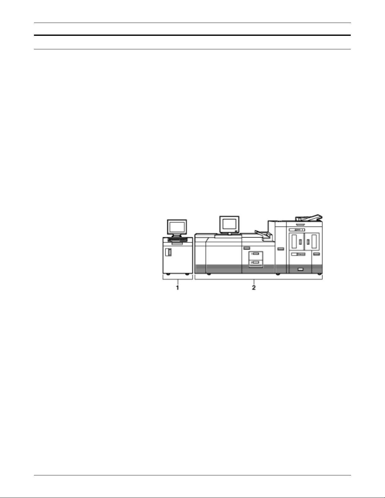
The DocuPrint 96/DocuPrint 96MX LPS consists of two separate
units illustrated in figure 1.
• System controller
• Printer.
Figure 1. DocuPrint 96/DocuPrint 96MX LPS
1 System controller
2 Printer
xxx XEROX DOCUPRINT 96/DOCUPRINT 96MX LPS OPERATIONS REFERENCE
Page 31

DocuPrint 96/DocuPrint 96MX system controller components
The system controller is the LPS subsystem that allows you to
interact with the printer. Use the keyboard display to enter
commands and select options that control the operation of the
printer.
Figure 2 shows the components of the system controller.
Figure 2. System controller components
INTRODUCTION
1 Keyboard display
2 Operator control panel
3 .25-inch cartridge tape drive
Keyboard display The keyboard display consists of a keyboard and display. Figure 3
shows the keyboard display.
Figure 3. Keyboard display
XEROX DOCUPRINT 96/DOCUPRINT 96MX LPS OPERATIONS REFERENCE xxxi
Page 32

INTRODUCTION
Operator control panel The operator control panel allows you to power the printer on and off,
boot the operating system software, and switch the LPS between
remote and local operation.
Figure 4 depicts the operator control panel
Figure 4. Operator control panel
1 Power On switch
2 Power Off switch
3 Power On indicator
4 Boot switch
5 Remote switch and indicator
6 Local switch and indicator.
DocuPrint 96/DocuPrint 96MX tape and cartridge devices
The DocuPrint 96/DocuPrint 96MX system uses three types of
devices. These devices are referenced by the labels TD0, TD1, and
TD2 since the physical device names are assigned with the
appropriate TDn at sysgen or at mini-sysgen.
For systems with an open-reel tape:
• TD0 is the default for the open-reel tape drive
• TD1 is the default for the 1/4 inch cartridge tape drive
• TD2 is the default for the 18/36 track cartridge tape drive
For systems without an open-reel tape:
• TD0 is the default for the 1/4 inch cartridge tape drive
• TD1 is the default for the 18/36 track cartridge tape drive
Refer to the
Guide
DocuPrint 96/DocuPrint 96MX LPS System Generation
for more information.
xxxii XEROX DOCUPRINT 96/DOCUPRINT 96MX LPS OPERATIONS REFERENCE
Page 33

DocuPrint 96/DocuPrint 96MX printer components
The printer is the LPS subsystem that processes the electronic
images and produces the printed report. Figure 5 depicts the
components of the DocuPrint 96/DocuPrint 96MX printer.
Figure 5. DocuPrint 96/DocuPrint 96MX printer
1 Processor feeder trays
2 Inverter feeder/stacker module (containing inverter, high-
capacity feeder, and high-capacity stacker bin)
3 Purge tray
4 Attention lig ht
5 Sample tray
6 Printer control console
INTRODUCTION
For more detailed information refer to the
DocuPrint 96MX LPS Operator Guide
.
DocuPrint 96/
XEROX DOCUPRINT 96/DOCUPRINT 96MX LPS OPERATIONS REFERENCE xxxiii
Page 34

INTRODUCTION
xxxiv XEROX DOCUPRINT 96/DOCUPRINT 96MX LPS OPERATIONS REFERENCE
Page 35

Communicating with the LPS
1. 1Setting LPS parameters
This chapter describes the parameters that may be set for the LPS.
The commands you enter control functions such as:
• Loading the operating syste m
• Switching between online and offline processing modes
• Setting the system to MICR mode
• Initiating printing
• Building and modifying source files
• Requesting sample prints of data, forms, fonts, and logos
• Obtaining accounting summaries
While print jobs are running, messages are displayed concerning the
status of the jobs and, if necessary, the unexpected occurrences that
require operator intervention.
The DocuPrint 96/DocuPrint 96MX LPS user interface:
• System keyboard display. Use the system keyboard display
to handle:
— Job programming and control features
— S ys te m utilit ies and diagnostics
— Paper management and feeder/stacker control
— Da ta Capture Utility
—Editor
The operator commands you can enter at the system controller
keyboard display are documented by this manual.
• Printer control console. Use the printer control console to
handle:
— Paper management and feeder/stacker control
— Jam clearanc e
— Printer diagn ostic functions
XEROX DOCUPRINT 96/DOCUPRINT 96MX LPS OPERATIONS REFERENCE 1-1
Page 36

SETTING LPS PARAMETERS
When you communicate with the printing system:
• Abbreviate all commands to the first three characters or spell
them out fully.
• Do not use a command entered in one language (for example,
English) interchangeably with the equivalent command in
another language (for example, French).
• Pressing a function key invokes the specified action. Do not
also press the <ENTER> key.
• Keyed-in commands are executed when you press the
<ENTER> key.
• Command delimiters are blank (space), end of line, comma,
and slash.
• Use only uppercase letters A to Z, and digits 0 to 9 in source file
names.
• System error and information messages are preceded by OS
and a four-digit code. The complete set of system messages is
documented in the
Message Guide
Xerox DocuPrint 96/DocuPrint 96MX LPS
.
• Messages without the OS four-digit code prefix are also
documented in the
Message Guide
Xerox DocuPrint 96/DocuPrint 96MX LPS
.
• A message acknowledging your request is displayed to provide
you with positive feedback. In system and operator dialog
examples, these messages are underlined to differentiate them
from system messages.
• The error message OS2710 Invalid command re-enter
displays when you enter an erroneous command or keyword
within a command.
1-2 XEROX DOCUPRINT 96/DOCUPRINT 96MX LPS OPERATIONS REFERENCE
Page 37

Installa tio n an d sys te m ge ne ra tio n
The initial considerations and procedures for installing a Xerox laser
printing syst em (LPS) and the operati ng system soft ware (OSS), th at
can be tailored to a site-specific configuration, are documented in the
Xerox DocuPrint 96/DocuPrint 96MX LPS Installation Planning
Guide
Generation Guid
preceding the table of contents in this manual.)
Your LPS service representative oversees the installation of the
DocuPrint 96/DocuPrint 96MX LPS.
User interface keyboard display
The DocuP rint 96/D ocuPrint 96MX LPS keyb oard d i splay major
steps are:
• Back up customer files.
• Install DocuPrint 96/DocuPrint 96MX multinational keyboard.
• Install DocuPrint 96/DocuPrint 96MX printer software.
SETTING LPS PARAMETERS
and
Xerox DocuPrint 96/DocuPrint 96MX LPS System
e. (Refer to the “Related publications” section
Detailed instructions are provided by the “Steps to perform a full
sysgen in character emulation mode” section in the
DocuPrint 96/DocuPrint 96MX LPS System Generation Guide
Xerox
.
XEROX DOCUPRINT 96/DOCUPRINT 96MX LPS OPERATIONS REFERENCE 1-3
Page 38

SETTING LPS PARAMETERS
Powering on and booting the LPS
This section discusses the power-on and boot process you use after
the first sysgen has been run.
If the LPS is online to a host computer and it has an emergency
power off cable, use the Remote button instead of the Local button.
The Remote button means that the host system controls powering
the LPS on or off. If you turn the power off by pushing the Off button
on the control panel, however, you can restart it by holding down the
On button until the Power indicator comes on.
If Autoboot was selected in the sysgen, the DocuPrint 96/
DocuPrint 96MX LPS system controller boots the operating system
automatically.
If not, follow this procedure:
Step 1. Press <B> on the keyboard to load the operating system software
(OSS).
Note: The operating system software must be loaded before
the system can finish the warm-up cycle.
Step 2. When loading is complete, the following messages appear on the
system controll er display:
LOADING PROGRAM.....
XEROX DP 96
LASER PRINTING SYSTEM
VERSION X REVISION Y
Copyright . . .
DISK ID: [ThirtycharacterIDrecord]
Step 3. Allow four to seven minutes for the printer to complete its warm-up.
Note: Before the LPS starts printin g , the syste m che cks print
quality and controls. Any adjustments, if necessary, are made by
the system to give you the best quality prints. The system also
checks print quality on an ongoing basis and may stop printing,
correct a quality problem, and resume where it left off.
Important If you enter a boot command for a device contained within the
peripheral cabinet, but the LPS is not configured with the specified
device, the system displays SCSI error messages and then displays
the boot menu.
Remedy this by pressing the Boot button again. When the LPS
displays the $ prompt, check the hardware configuration if the
peripheral cabinet is installed. If it is not installed, enter the BOOT
command for the configured device.
1-4 XEROX DOCUPRINT 96/DOCUPRINT 96MX LPS OPERATIONS REFERENCE
Page 39

Power loss
SETTING LPS PARAMETERS
If the DocuPrint 96/DocuPrint 96MX LPS loses power or the
communications link during online job processing, enter C or press
the Power Off button. The LPS responds by running its job recovery
procedures and displaying the job queue information it displayed
prior to the power loss. If the LPS does not respond this way, call your
LPS service representative for assistance.
XEROX DOCUPRINT 96/DOCUPRINT 96MX LPS OPERATIONS REFERENCE 1-5
Page 40

SETTING LPS PARAMETERS
System verification messages
If problems occur while OSS is performin g its syste m verif ication
tests, the DocuPrint 96/DocuPrint 96MX LPS displ a ys syste m
verification messages.
Table 1-1 shows system verification messages.
Table 1-1. System verification messages
Message Explanation
Operating in degraded mode Problem detected. Other messages will follow.
Devices not accessible
name,name,--
A configured syste m device is not in the system configur ation. The
missing devices are indicated by the following names:
DISK (disk)
FLOPPY (floppy)
TAPE (tape)
CARTP (quarter-inch tape)
HOST (online channel interface)
ENET (Ethernet)
RIP (raster image processor)
3480TP (1/2 inch tape)
Main memory missing: BankS) xx,
xy, xz,...
Hardware version mismatch -update configuration
Memory specified during the system configuration phase is
missing. The banks are displayed in 16K word sections.
The configured Advanced Imaging Subsystem (AIS )version and
the hardware AIS version number do not match.
AIP Firmware error A firmware error was detected. There is a fault in some part of the
AIP firmware.
AIP Download error There is a missing firmware file, a firmware file cannot be read, a
problem with the contents of the firmware file, or a download error
occurred causing the checksum to be incorrect.
Problem with AIPOS.sys --
Problems with accessing or reading the AIS firmware file.
file missing or invalid
Missing text and metric memory Problem accessing text and metric memory.
Missing bitmap memory Bad bank, cannot access bitmap memory.
Missing Ink-1 memory,
Missing Ink-2 memory,
Indicate that there is a bad bank, cannot access memory, or
memory is not available (not sysgened).
Missing PB-A-1 memory,
Missing PB-A-2 memory,
Missing PB-B-1 memory, or
Missing PB-B-2 memory
If any of the next four messages is displayed, re-sysgen the system and update the configuration. If this should
fail, contact your systems specialist or Xerox Customer Service for resolution.
Graphics memory not available-Update configuration
Ink memory not available-Update configuration
PB-B memory not available-fatal error
n
-2 memory not available--
PBfatal error
1-6 XEROX DOCUPRINT 96/DOCUPRINT 96MX LPS OPERATIONS REFERENCE
Graphics memory is not present according to the hardware, but is
sysgened in.
Ink memory is not present according to the hardware registers, but
is configured into the system.
Page buffer B memory is not present according to the hardware
registers, but is configured into the system.
Highlight page buffers memory is not present according to the
hardware registers, but is configured into the system.
Page 41

SETTING LPS PARAMETERS
Table 1-1. System verification messages (continued)
Message Explanation
SYSTEM NOT OPERATIONAL Devices were missing, or main memory i s below 128K words. The
system probably is unable to function even in a degraded mode if
this message is displayed. If this message is not displayed, the
system may be able to print, but its operation is degraded.
You can invoke any system function, although some functions may
not execute or may cause a system crash. For example, the lack
of AIS memory does not impact a file editing session, but that lack
of AIS memory would abort printing.
The above messages indicate that the system is not fully
functional. Use of the system at such a point is questionable.
Contact the LPS service representative for assistance in making
your LPS operational.
XEROX DOCUPRINT 96/DOCUPRINT 96MX LPS OPERATIONS REFERENCE 1-7
Page 42

SETTING LPS PARAMETERS
Printer communication link
The system stops all processing and restarts if a system controller
problem occurs.
The DocuPrint 96/DocuPrint 96MX LPS has an interface between the
system controller and the printer, part of which is called the client
layer. The system initializes the client layer to establish
communication between the system controller and the printer after
system initialization, after communication is lost, or at the request of
technical personnel (see the section “PSC (printer subsystem
controller)“ later in this chapter).
The system's ancillary Printer message (AIM) processor task
establishes communication with the printer, executes client layer
initialization, and displays status messages. If a problem initializing
the client layer occurs, AIM attempts to establish communication two
more times and to initialize the client layer. An attempt lasts between
20 seconds and two minutes. If these attempts fail, AIM prompts you
with Retry ClientLayer initialization? (Y/N).
If you enter N, AIM displays Enter PSC when you wish to
attempt connection to Printer.
Thus you choose between using the system controller for nonprint
tasks and loading the communication software again with the PSC
command.
Note: If the PSC command fails two times, reinitialize the printer by
turning the power off, then on again.
1-8 XEROX DOCUPRINT 96/DOCUPRINT 96MX LPS OPERATIONS REFERENCE
Page 43

Table 1-2 lists sample messages.
Table 1-2. Sample messages
Message Explanation
SETTING LPS PARAMETERS
Attempting to establish
The system controller is connecting with the printer.
communication with the printer...
Communication with the printer is
System and printer communication is successfully established.
established
Initializing Client-Layer
Client laye r in it ialization is beginning .
protocol
Client-Layer is established The client layer has been initialized without errors. The system is
functional.
Printer Client-Layer is not
The printer does not answer client-layer requests.
responding
Printer failed to send
configuration
Failed to establish communication
The printer does not send all the printer configuration messages
during client layer initia l iz a ti on .
Three attempts to bring up the link layer have failed.
with the printer
!Link to printer is down Communication with the printer was lost during execution of a
nonprint task. Displays when the nonprint task completes.
!Loss of communication with the
The system controller is not receiving messages from the printer.
printer
Retry Client-Layer
Initialization? Y/N
Several attempts to initialize the client-layer have failed. You can
request initialization again or terminate the process to run nonprint
tasks on your DocuPrint 96/DocuPrint 96MX LPS.
!Sequence error-ESS is attempting
reconnection to printer.
!Link down-ESS is attempting
reconnection to printer.
!Device not ready-ESS is
attempting reconnection to
printer.
The system controller has attempted to send a message when the
line has failed. AIM is attempting to reestablish communication.
The link has dropped. AIM is attempting to establish
communication.
The printer is not acknowledging a message, the CSI controller is
not responding, or the printer is aborting its own messages. AIM is
attempting to establish communication.
XEROX DOCUPRINT 96/DOCUPRINT 96MX LPS OPERATIONS REFERENCE 1-9
Page 44

SETTING LPS PARAMETERS
PSC (printer subsystem controller)
Syntax PSC [AIP[,CSI][,CRIB][ [:0][:1][:2][:3]][,SCSI][,CLI]]
Parameters Table 1-3 describes the tasks initialized by utilization of the PSC
Use this command to download firmware to the specified printed wire
board assemblies (PWBAs) in the system controller.
command.
Table 1-3. Parameters of the PSC command
Parameter Description
AIP Downloads the AIPO S.SYS firmware and
performs diagnostics to check and initialize the
various types of memory used by AIS. The
messages Initializing AIP and
Downloading firmware (version ###)
display, followed by memory test messages.
CSI Sends the software for printer and controller
communication and reinitializes the client-layer.
The PS1061 Initializing CSI message
displays.
CRIB Downloads the CRIB firmware. If the CRIB
download was invoked by the operator or from a
hard boot, the firmware is downloaded
unconditionally. However, after a system crash,
the checksum of the firmware on the CRIB PWBA
is checked first. If the checksum is correct, the
download is not executed. The message
Downloading CRIB firmware (version)
displays.
SCSI Displays the current SCSI firmware version.
CLI Reinitializes the client-layer.
The SCSI firmware is downloaded to the SCSI printed wire board
(PWB) automatically.
If the download succeeds, no more messages display. If an error
occurs, refer to the
Message Guide
Xerox DocuPrint 96/DocuPrint 96MX LPS
.
Examples The CSI firmware can be downloaded at any time by entering:
PSC CSI
On the DocuPrint 96/DocuPrint 96MX LPS the printer must be idle to
run the PSC task. If the HIP task is in process when you request
PSC, the system prompts you to confirm the PSC request. If HIP is
running when you confirm the PSC request, then the HIP
communication line is disconnected. In addition, printer messages
sent but not yet processed may be lost.
Restriction You can restrict access to PSC with RCU.
1-10 XEROX DOCUPRINT 96/DOCUPRINT 96MX LPS OPERATIONS REFERENCE
Page 45

Configure a finishing or feeding device
The following describes how to configure a finishing or feeding
device.
Create the FCG.LIB file
Before you can configure a finishing or feeding device, you must
modify a text file called FCG.LIB containing the array of bytes (timing
values, constants, flags, and so on) that are loaded into the LPS nonvolatile memory (NVM) by the configuration process. The array is
known as the “personality profile” of the finishing device because it
indicates to the LPS how to communicate with the finishing or feeding
device.
The FCG.LIB file must have one entry for each finishing or feeding
device. Each entry consists of a label, an equal sign (=), and a set of
values. You create the label, which should help you identify the
device and indicate its configuration if possible. For example, a
saddle-stitch profile might be given the label SADLSTCH.
• Entries must begin with an alphanumeric character (0-9, A-Z).
• Each entry provides the NVM values for one finishing or feeding
SETTING LPS PARAMETERS
device.
Finishing device entry syntax
• Each entry must have a label that begins the record.
• Although the label may consist of more than eight characters,
the LPS processes only the first eight characters.
• The equal sign separates the label from the array values.
• Commas separate each array value from preceding and
following values.
• Only whole numbers can be entered for parameter values (no
decimals).
• There are no defaults for any parameter. All values must be
specific for the entry to be accepted.
• Each entry is terminated by a semicolon (;).
The FCG.LIB file can also include comment lines. Comment lines
must begin with a non-alphanumeric character.
label=OUT135, p1, p2, p3, p4, p5, p6, p7, p8, p9, p10, p11;
name attached to the profile entry.
label
OUT135
DocuPrint 96MX output device profile.
distinguishes the entry as a 4635 or DocuPrint 96/
XEROX DOCUPRINT 96/DOCUPRINT 96MX LPS OPERATIONS REFERENCE 1-11
Page 46

SETTING LPS PARAMETERS
Parameters Table 1-4 shows the parameters of the Finishing device entry.
Table 1-4. Parameters of the Finishing device entry
Parameter Description
p1= Time between Sheets
p2= Sheet Jam Time
p3= Time between Sets
p4= Set Ja m Time
p5= Time to Cycle Up
p6= Attributes
Specifies the minimum time the device
requires between the trail edge of one
sheet to the lead edge of the next sheet.
Range is 0-32767 ms.
Specifies the maximum time the LPS
waits for a sheet delivery signal after a
sheet exits before declaring a jam. Range
is 0-13000 ms.
Specifies the minimum time between the
trail edge of the last sheet of one set to the
lead edge of the first sheet of the next set.
Range is 0-32767 ms.
Specifies the maximum time the LPS
waits for a set delivery signal after a set
exits before declaring a jam. Range is 013000 ms.
Specifies the amount of time the LPS
should wait after the cycle up signal is
sent before the bulk input feeder is
capable of sending a sheet. Range is 032767 ms.
Allows additional control of the SF1 and
SF2 function signals. Valid values are 0:
ESS control, 4: Always on, and 8: Always
off.
p7= Statuses Supported
p8= Delivery Signal Type
p9= Delivery Start Adjust
Expects a status from the finishing device
as listed below:
S0: Offline or Not Ready, value is 1.
S1: Faulted, value is 2.
S2: Full, value is 4.
S3: Sheet delivered, value is 8.
S4: Set delivered, value is 16.
Range is 0-31. If all statuses are
supported, the value is 31. If no statuses
are supported, the value is 0.
Identifies the required delivery signal as
triggered by the lead edge or the trail
edge. Range is 0-1:
Lead Edge triggered = 0
Trail Edge triggered=1.
Adjusts the timing of the start of the
delivery signal. Range is -100 to +300 ms
for the lead edge, -100 to +75 ms for the
trail edge.
1-12 XEROX DOCUPRINT 96/DOCUPRINT 96MX LPS OPERATIONS REFERENCE
Page 47

Table 1-4. Parameters of the Finishing device entry
Parameter Description
SETTING LPS PARAMETERS
p10= Delivery Pulse Width
p11= End of Set Offset
Example GNTST = OUT13 5, 1000 , 1500, 2000, 3500, 0, 2, 31, 0, 0, 0, 0;
Feeding device entry syntax
Adjusts the timing of the termination of the
delivery signal. Only applies to the trail
edge of the sheet; not applicable to the
lead edge. Range is 30—110 ms.
Informs the LPS of the amount of time
required between the sheet delivery and
set delivery signals. Range is 0-255.
label=IN135, p1, p2, p3, p4, p5;
name attached to the profile entry.
label
IN135 distinguishes the entry as DocuPrint 96/DocuPrint 96MX input
device profile.
XEROX DOCUPRINT 96/DOCUPRINT 96MX LPS OPERATIONS REFERENCE 1-13
Page 48

SETTING LPS PARAMETERS
Parameters Table 1-5 shows the parameters of the Feeding device entry
command.
Table 1-5. Parameters of the Feeding device entry command
Parameter Description
p1= Time to Feed sheet
p2= Time to Cycle Up
p3= Attributes
p4= Statuses Supported
Specifies the time required by the bulk
feeder between the feed sheet command
being received and the required sheet’s
arrival at the first LPS sensor. Range is 0500 ms.
Specifies the amount of time the printer
should wait after the cycle up signal is
sent before the feeder is capable of
delivering the first sheet of paper. Range
is 0-32767 ms.
Specifies which speci fi c sto cks ar e
supported by the bulk feeder, as listed
below:
D1: Drilled pap e r
D2: Ordered stock
Range is 0-7.
Receives a status from the feeding
device, as listed below:
S5: Bulk Input Medium Low
S6: Not Ready
S7: Sheet fed
Range is 0-7.
p5= Feed Signal Adjust
Specifies the duration of the feed sheet
command the LPS gives to the bulk
feeder. Range is 10-100 ms.
Example GENFD =IN1 35, 200, 800, 7, 3, 45;
Procedure The procedure follows:
Step 1. Open this file within the text editor by entering: EDIT FCG.LIB.
Step 2. Key in the entry record for the finishing device to be configured or
modify the array values if necessary.
Step 3. Save the file.
Step 4. Exit the Editor.
1-14 XEROX DOCUPRINT 96/DOCUPRINT 96MX LPS OPERATIONS REFERENCE
Page 49

SETTING LPS PARAMETERS
Step 5. Submit the values for the printer specified by the entry by entering
profile-label
FCG
.
System response:
1. The LPS verifies that no print job is being processed. If the LPS
is processing a print job, the LPS displays the message
OS1970 FCG exiting: Unable to run during a
print job.
2. If no print job is being processed, the LPS accesses the
FCG.LIB file. If this file does not exist, the LPS displays the
message OS1971 FCG exiting: FCG.LIB not present
on system.
3. If FCG.LIB is found, the LPS checks for the specified entry label
in the file. If the entry label is not in the file, the LPS displays
the message OS1972 FCG exiting: Unable to locate
entry label. If the specified entry label appears in the file
more than once, the LPS displays the message OS1973 FCG
exiting: Duplicate profile entries.
4. If the specified entry label is found, the array values for the
entries are checked to verify that they are integers within range.
If they are not, the LPS displays the message:
OS1978 FCG exiting: Data value is out of range.
5. Finally, the number of values in the entry is checked to verify
that no more than 11 values are specified. If an incorrect
number of parameters are specified, the LPS displays the
message OS1976 FCG exiting: Invalid profile
encountered.
6. If an error occurs during step 4 or 5, the LPS displays the
message Profile not loaded.
7. If no error occurs during step 4 or 5, the LPS copies the array
values to the printer’s, and the LPS displays the message
OS1974 FCG exiting: Profile for
successfully loaded.
FCG (disp lay the prof i le l abe l s)
Use this command to display the profile labels in the FCG.LIB file.
Logon Level Levels 2 through 5.
Syntax FCG
<profile-name>
XEROX DOCUPRINT 96/DOCUPRINT 96MX LPS OPERATIONS REFERENCE 1-15
Page 50

SETTING LPS PARAMETERS
FCG (c onfigure a fin i shing or feedi ng devi ce)
Use this command to load into printer memory the personality profile
the LPS must use to communicate with the finishing device or bulk
feeder. The personality profile is an entry in a text file called
“FCG.LIB.” On ce this f ile i s cr eated, i t is preser ved across sy sgens.
Logon Level Levels 2 through 5.
Syntax FCG {
profile-label
}
Parameters Table 1-6 shows the parameters used in FCG to configure a finishing
or feeding device.
Table 1-6. Parameters of the FCG (configure a finishin g or
feeding device) command
Parameter Description
profile-label
Specifies the entry in the FCG.LIB file to be sent to
the printer.
Reference For more detailed procedural information, refer to the
DocuPrint 96MX LPS Operator Guide
.
DocuPrint 96/
FCG SHOW (check finishing or feeding device settings)
Use this command to check the settings for the finishing or feeding
devices configured for the LPS.
Logon level Levels 2 through 5.
Syntax FCG SHOW
Restrictions SHOW cannot be abbreviated to SHO.
Reference For procedural information, refer to the
DocuPrint 96MX LPS Operator Guide
1-16 XEROX DOCUPRINT 96/DOCUPRINT 96MX LPS OPERATIONS REFERENCE
DocuPrint 96/
.
Page 51

SETTING LPS PARAMETERS
FCG procedures
Use this task to:
• Send the configuration values for a feeding or finishing device
to the printer
• Display the current device configuration values.
Configure task Table 1-7 shows the command to send feeding or finishing device
configurations to the printer.
Table 1-7. Parameters of the FCG SHOW (check finishing or
feeding device settings) command
Parameter Description
FCG
profile-label
profile-label
To display all profile labels for the feeding or finishing device, enter
the following command:
FCG
To display the current device configuration values, enter the following
command:
FCG SHOW
Note: SHOW cannot be abbrev iated to SHO.
The name assigned to the feeding or finishing
device configuration.
XEROX DOCUPRINT 96/DOCUPRINT 96MX LPS OPERATIONS REFERENCE 1-17
Page 52

SETTING LPS PARAMETERS
Verifying LPS status
Verifying system version and time
OCS (system version display)
Syntax OCS
Status lines Figure 1-1 is an example of the OCS status display.
The system automatically displays messages describing paper tray
status, output bin status, and required operator actions in the system
message area. These messages are OSXXXX messages such as
OS2080 Paper tray x is empty and OS2210 Bin x full.
The following describes how to verify system version and time.
Use this command to verify OSS version information.
OCS
System version xx; IOT Software version xx;
OCS version xxx; Command table version xxxx;
System class x; Disk ID: xxxx
OS1000 Ready For Commands
Time and date displays
The following describes how to verify time, date and status.
Keyboard display The date and time display (figure 1-2) appears on the keyboard
display in the upper right corner of the screen. The input device,
output device, and host device have status lines that are always
displayed under the time entry. These lines are described in the
“Status lines” section (table 1-8).
Status lines Figure 1-2 shows the various lines of the time, date and processing
status display.
HH:MM:SS
uuuuvvvv
wwww
yyyzzzz
1-18 XEROX DOCUPRINT 96/DOCUPRINT 96MX LPS OPERATIONS REFERENCE
Page 53

SETTING LPS PARAMETERS
Table 1-8 shows the status display entries for time and date displays.
Table 1-8. S tatus display entri es
Status Explanation
uuuu Input status. May be all blanks, Wait , Actv, Sat., or
Stop.
vvvv Input source. May be all blanks, Tape, Disk, Host, or
Enet.
wwww Output status. May be all blanks, Wait, Actv, Stop, C-
up, or Jam.
yyyy Current host. May be all blanks, XNS, or Host.
zzzz Host stat us. May be Offl, Nrdy , Wait, Recv, Send, Spnd,
OnLP, ATTN, or Sesn.
XEROX DOCUPRINT 96/DOCUPRINT 96MX LPS OPERATIONS REFERENCE 1-19
Page 54

SETTING LPS PARAMETERS
Verifyi ng syst em stat us
PROBLEM
You can increase the efficiency of service calls by providing the
representative with the 6-digit dispatch code generated by the OSS
problem utility. Run this utility:
• Before placing a service call
• When the system directs you to key in the PROBLEM
command (since it detects a problem it cannot correct).
Use this command to access the dispatch code.
Syntax PROBLEM
Procedure The display shown in figure 1-3 appears.
Figure 1 -3. Initia l P ROBL E M displa y .
PROBLEM C00 PROBLEM ANALYSIS RUNNING
PROBLEM ANALYSIS RESULTS-- DISPATCH CODES
1. TO REPORT ADDITIONAL PROBLEMS
2. NO MORE PROBLEMS TO REPORT.
INDICATE SELECTION BY ENTERING NUMBER.
##.##.##
(message)
A sample dispatch code is 10.00.18 SYSTEM REPORTED
PRINTER PROBLEM.
If you want to report additional problems, enter the number 1. Then
the system prompts you to identify the type of problem (figure 1-4).
Figure 1 -4. Prompt for PROBLEM type.
WHICH OF THE FOLLOWING TYPES OF PROBLEMS DO YOU WISH
TO REPORT?
1. COPY QUALITY PROBLEMS
2. FREQUENT JAMS
3. OUTPUT TRAY PROBLEMS
4. PAPER TRAY PROBLEMS
5. TAPE PROBLEMS
6. OTHER SYSTEM PROBLEMS
7. NO OTHER SYSTEM PROBLEMS
INDICATE SELECTION BY ENTERING NUMBER.
1-20 XEROX DOCUPRINT 96/DOCUPRINT 96MX LPS OPERATIONS REFERENCE
Page 55

SETTING LPS PARAMETERS
When you enter 7, the system provides a code that you should record
and report to your LPS service technician (figure 1-5).
Figure 1 -5. Field Service code display.
CALL THE FIELD SERVICE DISPATCHER AND REPORT THESE
NUMBERS
##.##.##
OPERATOR---INDICATE THE ACTION YOU HAVE TAKEN.
1. SERVICE CALL HAS BEEN PLACED.
WAITING FOR SERVICE
2. SERVICE CALL HAS BEEN PLACED.
RETURN TO THE OPERATING SYSTEM
3. SERVICE CALL HAS BEEN COPIED FOR LATER CALL.
RETURN TO THE OPERATING SYSTEM
4. NONE OF THE ABOVE.
RETURN TO THE OPERATING SYSTEM
INDICATE SELECTION BY ENTERING NUMBER
Before entering 1, 2, 3, or 4, ensure that you record the 6-digit
dispatch code to report to your service representative.
If you enter 2, 3, or 4, you return to the operating system and may
resume printing. If you enter 1, the system cannot be used until it has
been repaired.
XEROX DOCUPRINT 96/DOCUPRINT 96MX LPS OPERATIONS REFERENCE 1-21
Page 56

SETTING LPS PARAMETERS
Setting LPS parameters
Setting system parameters
SETTIME (set time or date)
The following section describes how to set parameters for various
functions of the LPS.
The following describes how to set parameters for specific functions
of the LPS.
Use this command to set the system time or date or both.
Syntax SETTIME [
Parameters Table 1-9 shows the parameters used in setting time and date for the
LPS.
Table 1-9. Parameters of the SETTIME (set time or date)
Parameter Description
mm
/
dd
yy
hh
mm/dd/yy
command
] [
hh:mm[:ss
The month, represented by either a number
between 1 and 12, for example, 3 for March, or a
three-character abbreviation determined by the
language specified in the last full sysgen, for
example, MAR for March. If English is the
language, the abbreviations are: JAN, FEB, MAR,
APR, MAY, JUN, JUL, AUG, SEP, OCT, NOV,
DEC.
Represents a date-field delimiter, which can be a
slash (/) or a hyphen (-).
The day of the month.
The last two digits of the year.
The hour, using a 24-hour clock (milit ary time).
]]
:
mm
ss
Restrictions You can enter this command only when the system is idle (such as
offline with no background tasks running, and not printing) and only
if you are logged in at class 2 or higher. (Refer to the “Setting file
access and task execution privileges” section of this chapter.)
1-22 XEROX DOCUPRINT 96/DOCUPRINT 96MX LPS OPERATIONS REFERENCE
The time- fie ld de lim it e r, w hich is a colon (:) .
The minute of the hour.
The seconds field. Optional.
Page 57

SETTING LPS PARAMETERS
ALIGN (set page print alignme nt)
Use this command to align the laser image with the paper. The
alignment values for each printer must be set at least once, but they
remain relatively constant. The alignment values you enter are
retained by the system until you change them.
Syntax ALIGN[/300 | /600] [[scans],[dots,][TEST]]
Parameters Table 1-10 shows the parameters used in setting the page and print
alignment.
Table 1-10. Parameters of the ALIGN (set page print alignment)
command
Parameter Description
/300 Displays or sets the current alignment in 300 dpi.
/600 Displays or sets the current alignment in 600 dpi.
scans
dots
TEST Prints a TEST form.
If no parameters are specified, the current alignment values are
displayed.
For printing, the LPS rounds the dot position value to the nearest
multiple of 8. If this correction falls outside the permissible range, the
LPS must be adjusted mechanically to bring it into the range of the
ALIGN command limitations.
The system extrapolates alignment values for all other paper sizes
after you set the alignment for one paper size.
You can also specify alignment values for the diagnostic mode when
LOCKOUT is in effect. This feature is designed for the service
technician. Refer to the DALIGN section in chapter 11.
Restrictions The following are the restrictions to setting parameters for page print
alignment.
The number of scan lines (across a portrait page
or down a landscape page) in dots. The range is 75 to 296 inclusive. The default is 1.
The number of dots along each scan line (up a
portrait page or across a landscape page) in dots.
The range is 0 to 1499 inclusive. The default is 0.
The displayed value is rounded to the nearest
multiple o f 4.
• Do not use the TEST parameter when the system is online. If
you do, the OS7400 Invalid JDE/JDL for ON-LINE
processing message displays.
• Do not request an alignment sample when a print job is in
progress since the system will make the alignment settings
without printing the test form.
XEROX DOCUPRINT 96/DOCUPRINT 96MX LPS OPERATIONS REFERENCE 1-23
Page 58

SETTING LPS PARAMETERS
Procedure An alignment form is provided with the syst e m software to ensure
proper alignment of output. Using the Align command with the TEST
parameter, shows alignment values (scan lines and dots), the current
date and time, and disk id. The file name of this form is TEST, and it
resides in the FRM directory. If the TEST parameter is specified and
the LPS is offline, the test form is printed automatically; this is the
equivalent of using ALIGN and SAMPLE TEST.FRM.
It is best to compile and use the test alignment form prior to running
other print jobs. Always use the alignment form to adjust the LPS
when you run jobs using preprinted forms. In addition, always
sample the test form after any LPS mechanical adjustments are
made.
A quick way to test alignment is to sample the form, and then fold it
in half once on the dot orientation and once on the scan line
orientation. This provides you with an easy measurement of how
many dots or lines to add or subtract. A fter correct ing the alignment
with the ALIGN command, resample the form and check for any
further variation that may be needed. For all but the most critical
applications, it is sufficient to get the alignment to the point where the
center line is visible on each side of the fold.
Examples The following illustrates how to run a test, change a parameter and
retest.
• ALIGN/300 80,24,TEST
Alignment is 80 scan lines and 24 dots
• ALIGN
Alignment is 80 scan lines and 24 dots
• ALIGN ,16
Alignment is 80 scan lines and 16 dots
• SAMPLE TEST.FRM
If resetting the alignment with ALIGN does not provide the desired
result, modify the PDE BEGIN statement in the job’s JSL file and
recompile it. Refer to the
Reference
DISPLAY (set display format for messages)
Use this command to specify the format (ASCII, hexadecimal, or
both) in which printer-related messages are displayed. If you request
ASCII, the hexadecimal codes for fault, hint, and information
messages are mapped into user friendly ASCII messages. If you
request hexadecimal, these messages are displayed only in
hexadecimal. If you request both, they are displayed in ASCII and in
hexadecimal.
Syntax DISPLAY {ASCII | HEX | BOTH}
.
DocuPrint 96/DocuPrint 96MX LPS PDL
ASCII is the set condition from sysgen, but it will remain as changed.
1-24 XEROX DOCUPRINT 96/DOCUPRINT 96MX LPS OPERATIONS REFERENCE
Page 59

ENERGY
SETTING LPS PARAMETERS
The default timeout value for the energy saver mode is 90 minutes.
The power saving mode of the printer powers off most printer base
machine functions, but leaves the printer control system and the
printer monitor functioning. The Attention light and alarm are idle in
the energy saving mode.
Use this command to establish another timeout value for the printer.
The printer uses this value to calculate the time it may remain idle
before switching into the power saving mode. The timeout value is
saved across boots and power-offs. The system exits the energy
saver mode when the printer is given a message by the system
controller.
Syntax ENERGY [
timeout
]
Parameters Table 1-11 shows the parameters of the ENERGY com man d.
Table 1-11. Parameters of the ENERGY command
Parameter Description
timeout
The number 0 or a number within the range 10
through 65,535 minutes. 0 indicates that a timeout
should never occur. If you omit the timeout value,
the system displays the current timeout value.
XEROX DOCUPRINT 96/DOCUPRINT 96MX LPS OPERATIONS REFERENCE 1-25
Page 60

SETTING LPS PARAMETERS
MICR (set MICR mode)
Use this command to set the system in Magnetic Ink Character
Recognition (MICR) mode.
Syntax MICR [ON | OFF]
Parameters Table 1-12 shows the parameters of the MICR mode.
Table 1-12. Parameters of the MICR (set MICR mode) command
Parameter Description
ON Sets the system to MICR mode. This mode forces
print quality level 5 (PQ5), Lead Edge Lightening,
to Off.
OFF Sets the system to non-MICR mode. This causes
the system to revert to the EDGE and DARKNESS
settings that were in effect before MICR mode was
entered.
No parameter indicates that the system should display the current
MICR mode setting.
Restriction This comma nd is valid only if the MICR option is installed in the
system (DocuPrint 96MX systems).
The system does not accept the EDGE and DARKNESS commands
while in MICR mode. In MICR mode, the EDGE and DARKNESS
settings remain as they were before entering MICR mode, but the
internal xerographic processes are forced to perform as if
DARKNESS 5 and EDGE OFF were in effect.
The controller does not allow the MICR option to be turned off or on
while it is printing to prevent signal strength errors. MICR mode can
be turned on and off when the printer is cycled down.
If you enter the command when a job is printing, the LPS displays a
message telling you the command will stop output. It then prompts
you to confirm the request.
At job completion, the MICR mo de will r etu rn to the mode spec if ied
as the default during the Sysgen process.
1-26 XEROX DOCUPRINT 96/DOCUPRINT 96MX LPS OPERATIONS REFERENCE
Page 61

Setting parameters for print jobs
The following s ection descr ibes set tin g parameter s for pri ntin g tasks
on the LPS.
Reallocating space to the print file
The following describes how to reallocate space for print files.
REA (reallocate print file)
Use this command to set the size of the print file on the system disk.
The recommended print file size is at least 400 cylinders. The
recommended print file size is created during system generation, but
you may need to increase its size based on your installation’s
requirements. The print file size can be increased or decreased in
size any time the system is idle.
The command informs you of the number of cylinders allocated and
the number of cylinders actually usable by input and output. The
system maintains and updates a permanent record of all cylinders
deemed unusable for printing if bad sectors are detected while
running a print job. These unusable cylinders are removed from use
until the disk is reformatted during a full system generation.
SETTING LPS PARAMETERS
Syntax REALLOCATE [
The parameter set, [
discussed in this section.
This command invokes the reallocation processor, which determines
current space availability for the print file. If any parameter is
entered, no questions are asked during the reallocation process.
The warning messages that inform you not to disturb the process are
still displayed. The size of the current print file is not displayed.
REALLOCATE proceeds by calculating the current size of the file,
then deletes it. The desired size is calculated by using the previous
size if the new one is not specified. The REALLOCATE then
recreates the print file.
ddd
| ? | !]
ddd
| ? | !], describes the print file which is
XEROX DOCUPRINT 96/DOCUPRINT 96MX LPS OPERATIONS REFERENCE 1-27
Page 62

SETTING LPS PARAMETERS
Print file parameters Table 1-13 shows the parameters for setting the size of the print file.
Table 1-13. Parameters of the REA (reallocate print file)
command
Parameter Description
ddd
Represents a decimal number, which is the
number of cylinders requested for the new print
file. If ddd is larger than the maximum contiguous
space available, it makes the largest size print file
it can. If ddd is less than the minimum size for your
system configuration, the reallocation process
exits and displays the REQUESTED PRINT FILE
IS TOO SMALL message.
? Creates up to the default size for the print file if one
does not exist. If a print file already exists, a print
file of the same size is created. The default size is
400 cylinders. This command is specifically for
use in the SYSGEN.CMD file.
! Creates a default size print file even if one already
exists.
If the print file size is less than the minimum configuration or is too
small to handle the job, the printer cycles up and down. This is not
desirable.
1-28 XEROX DOCUPRINT 96/DOCUPRINT 96MX LPS OPERATIONS REFERENCE
Page 63

SETTING LPS PARAMETERS
Procedure If you enter REALLOCATE without parameters, the system executes
the complete interactive process.
After you invoke REALLOCATE, the following message displays:
DO you want to reallocate a different size (yes/no)?
If you do not wish to change the current print file size, enter NO. The
**** Resuming normal operation **** message displays,
and processing exits without changing the print file size.
If you enter YES, the prompt to enter the size displays.
REA VERSION D01 NUMBER OF CYLINDERS IN THE CURRENT
PRINT FILE IS aaa (bbbb sectors)
aaa and bbbb are the number of cylinders and sectors respectively
in the print file currently on the disk.
Number of cylinders available for print file is ccc
(dddd SECTORS)
The value shown is the largest contiguous free space on the disk and
is presented in cylinders and sectors.
How many cylinders should the print file contain?
zzz
Enter a value of at least 400. This value must be at least 50 cylinders
less than the total free space on the disk. A value of more than 400
is beneficial in the event that the system experiences disk saturation
situations. Otherwise, the 400 value should be sufficient. If more
than the maximum cylinders available is requested, a print file of the
maximum number of available cylinders is created.
n cylinder print file allocated with m usable
cylinders
n
is the number of cylinders requested and allocated to the print
file.
m
is the number of usable cylinders within the print file (allocated
cylinders minus the cylinders flagged as unusable within the
print file).
**** Resuming normal operation ****
At this point, the reallocation processor has completed its function,
and the system is ready for normal operation.
Caution: Interrupting the reallocation process sometimes renders
sections of the disk unusable.
If REA completes by displaying PRINT FILE TOO SMALL, no print
file has been cre a te d . In this case use the COMPRESS DP1:
command to create sufficient free disk space. Then use REA again.
If REA fails a second time, back up or delete user files on the disk, or
move them to another disk.
XEROX DOCUPRINT 96/DOCUPRINT 96MX LPS OPERATIONS REFERENCE 1-29
Page 64

SETTING LPS PARAMETERS
REA and disk m anagement
Manage cylinders in order to maintain the required minimum print file
size. Doing so assures printing without input or output processing
lockup.
Procedure The message Requested Print File is Too Small appears
if the value you enter is smaller than the minimum number of
cylinders.
If the minimum size print file cannot fit on the disk:
Step 1. Enter COM DP0: (or COM DP1:, or COM DP2: , or COM DP3:).
Use this command to compress the files on the disk, creating
contiguous free space.
Step 2. Enter the REA command again.
If the minimum size print file can fit on the disk:
Step 1. Enter FCH DP0: (or FCH DP1:, or FCH DP2: , or FCH DP3:).
This displays the disk addresses and number of blocks available and
the regions of the disk.
Step 2. Check the value reported for the Largest Number of Blocks to identify
the space available for the print file.
Step 3. Multiply the minimum number of cylinders by 400 to identify the
minimum number of blocks needed.
Step 4. Enter FIL/EX DP0: (or FIL/EX DP1: or FIL/EX DP2: or FIL/EX DP3:).
This allows you to identify the fil es t hat can be deleted from the disk,
and to decide the combination of files to delete to provide enough
free space.
Step 5. Delete files you have selected.
Step 6. Enter COM DP0: (or COM DP1:, or COM DP2: , or COM DP3:).
Use this command to compress the files on the disk, creating
contiguous free space.
Step 7. Enter FCH DP0: (or FCH DP1:, or FCH DP2: , or FCH DP3:).
Use this command to veri fy t hat the Larg est Number o f Blocks va lue
is greater than the minimum print file size.
Step 8. Delete more files and compress the disk again if the Largest Number
of Blocks value is too small. (You may delete the HIPBF.SYS file if
HIP is not loaded on the LPS and your site has backed up the file for
the LPS.)
Step 9. Enter the REA command again.
REA and on line re p ort spooling
You can reallocate small print files by restricting input processing to
control report spooling. Online users can specify the number of
reports the input task can process ahead of output. Refer to the
“LEASH” section in chapter 7 for additional information.
1-30 XEROX DOCUPRINT 96/DOCUPRINT 96MX LPS OPERATIONS REFERENCE
Page 65

Setting job parameters
FONTS
SETTING LPS PARAMETERS
The following section describes the different parameters that can be
set for individual printing jobs.
Use this command to optimize the reallocation of task memory by
specifying the maximum number of fonts the system attempts to
keep resident in memory during a print job. This value can have a
significant impact on system performance for some jobs.
Syntax FON TS
number
Parameters Table 1-14 shows the parameter setting for FONTS.
Table 1-14. Parameters of the FONTS command
Parameter Description
number
A positive, non-zero integer less than 129, which
specifies the maximum number of active fonts per
print job. No single page (or both sides of a duplex
sheet, combined) printed can invoke more fonts
than specified. Ensure that this number includes
all fonts and logos used on forms and variable
data.
The fonts for literals, logos, and the variable data
in the form, if a form is used, must be included in
the specified number.
You can specify a larger number of fonts than will
ever be used on a single page, thus allowing font
changes on a page-to-page basis without
throughput degradation (loss of printing speed) if
all the fonts can be loaded into memory. If
is omitted, the system displays the value currently
in effect. The default is 32 fonts.
number
The FONTS number remains in effect until the FONTS command is
reissued or a new operating system is generated.
A print job may actually use more than the specified number of fonts
as long as no more than this number of fonts is called for on a single
page or on both sides of a duplex page, combined. If, during a print
job, the current FONTS value is exceeded while processing a page
(such as the total number of fonts required for form printing plus
those required for variable data printing), the system aborts that job
and displays the message OS2885 Max number of fonts
exceeded. Enter new value. Restart job.
XEROX DOCUPRINT 96/DOCUPRINT 96MX LPS OPERATIONS REFERENCE 1-31
Page 66

SETTING LPS PARAMETERS
FORMS
Use this command to optimize the allocation of task memory by
specifying the maximum number of forms the system attempts to
keep in forms memory during print job processing. This value can
have a significant impact on system performance for some jobs.
Syntax FORMS
Parameters Table 1-15 shows the parameter setting of the FORMS command.
Table 1-15. Parameters of the FORMS command
Parameter Description
number
A number larger than 1 allows form changes on a page-to-page basis
without throughput degradation if all the forms can be loaded into
memory .
Restriction The FORMS command remains in effect until you reissue the
FORMS command or a new operating system is generated.
GRAPHIC
Use this command to optimize the allocation of task memory by
specifying the maximum number of graphics the system attempts to
keep in graphic memory during print job processing. This value can
have a significant impact on system performance for some jobs.
number
A number between 1-64 inclusive. It sets the
maximum number of active forms per print job. If
you omit
currently i n e ffect .
number
, the system displays the value
Syntax GRAPHIC
Parameters Table 1-16 shows the parameter of the GRAPHIC command.
Table 1-16. Parameters of the GRAPHIC command
Parameter Description
number
Restrictions The following are the restrictions to setting t he GRAPHIC parameter:
number
An integer between 16 and 128. If you omit
number, the system displays the value currently in
effect.
• No single page printed can invoke more than 16 graphics.
Ensure this number includes all graphics used on a form for this
page if a form is used.
• The GRAPHIC command remains in effect until you reissue it or
a new operating system is generated. A print job can use more
than the specified number of graphics as long as no more than
16 are called for on a single page.
1-32 XEROX DOCUPRINT 96/DOCUPRINT 96MX LPS OPERATIONS REFERENCE
Page 67

Adjusting print image darkness
DARKNESS
Syntax DARKNESS [
Parameters Table 1-17 shows the para m eter of the DARKNESS command.
SETTING LPS PARAMETERS
The following describes the adjustment of the darkness of the print
image.
Use this command to make the printed images lighter or darker.
When the command is entered without any parameters, the current
setting is displayed.
level
[,TEST]]
Table 1-17. Parameters of the DARKNESS command
Parameter Description
level
A number between 1 and 9 inclusive. Use a higher
number to darken the image; use a lower number
to lighten the image.
TEST Prints a sample with the darkness level you
specified.
Restriction The system does not accept this command when MICR mode is on.
XEROX DOCUPRINT 96/DOCUPRINT 96MX LPS OPERATIONS REFERENCE 1-33
Page 68

SETTING LPS PARAMETERS
Lightening high-density images
EDGE
Syntax EDGE [NORMAL | STRESS | OFF]
Parameters Table 1-18 shows the parameters that may be set for EDGE.
The following explains lightening high-density images.
Use this command to decrease the image density on the leading
edge of the page, and thus limit how often paper jams. The change
is applied the next time the printer cycles up. When the command is
entered without any parameters, the current setting is displayed.
Table 1-18. Parameters of the EDGE command
Parameter Description
NORMAL Invokes light screening.
STRESS Invokes heavy screening.
OFF Leaves the image density on the edge of the paper
unchanged.
no parameter displays the current setting.
Restriction The system does not accept this command when MICR mode is on.
Recommendation EDGE prevents fuser jams best when ALIGN is set at 1,0.
Finishing Exerciser Utility
FEX
OFF the setting after sysgen, but it remains as changed.
If you enter the command when a job is printing, the LPS displays a
message telling you the command will stop output. It then prompts
you to confirm the request.
The following section describes the finishing exerciser utility.
Use this command to generate multiple data set test cases through
a third-party finishing device connected to the printer.
Syntax FEX
Restriction FEX cannot run during a print job.
Process The Finisher Exerciser Task will pres ent the operator wit h a set of
questions to allow FEX to construct a temporary test case on the
DocuPrint 96 /DocuPri nt 96 MX LPS. FEX wi ll inv oke this te st ca se to
1-34 XEROX DOCUPRINT 96/DOCUPRINT 96MX LPS OPERATIONS REFERENCE
Page 69

SETTING LPS PARAMETERS
generate a print job that is designed to assist the operator in the
alignment of a third party finishing device that is attached to the
system.
At the user interface type the following:
FEX <ENTER>
The follow in g r esponse will be dis p layed.
OS0733 Finishing Exerciser Utility (FEX)
starting...
FEX will now check for the existence of the required JDL file
(FEXDMP.JDL). If it cannot be located on the system disk, the
following message will be displayed.
OS2920 FEX: Error, FEXDMP.JDL not found.
Recompile FEX.JSL
FEX will now ask for information that is required to develop the test
case. The following prompts will be displayed.
OS2922 Enter the TOTAL number of sets to create:
OS2923 Enter the number of pages per set:
ENTER FEEDER #:
Please select a papersize for this job from the
following menu:
1) US Letter (8.5 x 11 in)
2) US Legal (8.5x 14 in)
3) US Legal LEGAL KEYWORD
4) US B size (17 x 11 in)
5) A4 (8.27 x 11.69 in)
6) A3 (16.54 x 11.69 in)
7) Sysgen papersize
What size is loaded for this job?:
OS2924 Enter the FRM name (leave off the .FRM):
DO YOU WANT SF1 FUNCTION TO ALL SHEETS? (Y/N)
DO YOU WANT SF2 FUNCTION TO ALL SHEETS? (Y/N)
OS2835 Enter ‘D‘ for Duplex printing, ‘S‘ for
Simplex printing:
FEX now generates the test case as requested and invokes the LPS
to print the test job.
XEROX DOCUPRINT 96/DOCUPRINT 96MX LPS OPERATIONS REFERENCE 1-35
Page 70

SETTING LPS PARAMETERS
Setting file access and task execution privileges
This section explains the procedures for limiting access to files and
task execution.
Protecting access to files
The following describes how access to files may be restricted or
limited.
LOGON (restrict file access)
Use this command to restrict access to files of a given type (such as
those cataloged in a certain file directory) for a particular action
(record editing, deleting, and copying of files). It also allows your
installation to authorize or restrict certain system level commands.
(Refer to the RCU command.) Five user classes are provided, each
with varying degrees of access to files (as illustrated in table 1-23)
and operator command usage.
Syntax LOGON [1]
LOGON [ 2 | 3 | 4 | 5 [,passw ord]]
Parameters Table 1-19 shows the parameters of the LOGON command.
Table 1-19. Parameters of the LOGON (restrict file access)
command
Parameter Description
1,2,3,4, or 5 S pecifies the user classification. Tabl e 1-23
illustrat es ho w this cl as si fica t ion is related to t h e
file access and functions that are performed.
password
Passwords and Data Capture Utility It is possible to enter the LOGON command with the logon level and
the password on the same line separated by a comma:
LOGON 2,
Though this method is more expedient; you must be aware that if the
Data Capture Utility (DCU) log is on and you enter a LOGON
command in this format, the password will be captured on the DCU
log, making that password accessible to users at all security levels.
password
A 1 to 15 character string that consists of any
characters (including leadin g, nested or trailin g
blanks) on the keyboard. Levels 2 through 5 have
a default password that you can change.
For greater system security, always enter the LOGON command in
the following format:
LOGON security-level
When the system prompts you for the password, enter it. In this
format, the password is not captured on the DCU log.
1-36 XEROX DOCUPRINT 96/DOCUPRINT 96MX LPS OPERATIONS REFERENCE
Page 71

SETTING LPS PARAMETERS
Note: Any password you ente r in the later format must be in
uppercase letters.
Changing passwords A user already logged into class level 2, 3, 4, or 5 can change the
password for that level by keying in LOGON with no parameters. The
system then prompts for the new password.
If the preferred form LOGON n is used, you are requested to key in
the password, which is not displayed on the screen as it is keyed, nor
is any indication given as to the length of the password.
When the LOGON n password form is entered, the password is
displayed on the keyboard display as entered by the operator.
System level passwords are case sensitive. The default system level
passwords are in uppercase. Therefore, if you use lowercase to key
in any system level password, the password will not be recognized.
Login passwords you create are also case sensitive. Therefore,
subsequent entries of any new password must be entered in the
same case for the system to consider it valid.
Changing logon levels A password is always required to access a logon level higher than the
current level.
A password, however, may not be required to move from a higher
level to a lower level. For example, you are not required to enter a
password to access logon level 1, since level 1 is not password
protected. And, since logon levels 2 and 5 are designed for customer
use, you can also move from logon level 5 to level 2 without a
password. Also, until you set a password for level 2, you can move
from any higher level to level 2 without a password.
Moving from level 4 or 3 to level 2, or level 5 to 3 or 4, does require
a password.
SECURE (restrict file access)
Use this command to protect the following file types against
unauthorized access: CMD, CME, FNT, FRM, FSL, IMG, JDL, JSL,
LGO, PDE, TST, STK, and LIB.
Syntax SECURE
file-name.file-type
Parameters Table 1-20 shows the parameters of the SECURE command.
Table 1-20. Parameters of the SECURE (restrict file access)
command
Parameter Description
file-name
Specifies a one to six character name of a disk
file.
file-type
Specifies one of the directory types listed
above.
The following editor commands are affected by the secured file
feature: COPY, DELETE, FID, FILE, FIX, FLOPPY, GET, LIST,
MERGE, REVIEW, RNAME, and SAVE.
Restrictions A secured file cannot be copied to tape.
XEROX DOCUPRINT 96/DOCUPRINT 96MX LPS OPERATIONS REFERENCE 1-37
Page 72

SETTING LPS PARAMETERS
Secured files, access, and manipulation
The system supports the security feature by maintaining the security
characteristics of files that it manipulates (such as a renamed
secured file retains its security characteristics). An unsecured file
that replaces a secured file makes the file unsecured. However, if a
secured font is referenced in a forms source library (FSL) file
compiled at logon level 5, the FSL file and resulting FRM file are not
automatically secured.
It is your responsibility to secure the FSL and FRM files. Likewise, if
you copy a secured file to a new file or over an existing unsecured
file, the resulting file is unsecured.
You must be in logon level 5 to access any secured file. The only
exception to this is the FIX command. (Refer to the section “FIX
(modify font or logo file)“ in Chapter 2.) Fixing of fonts and logos is
unaffected by security. You can fix a secured font or logo at any
logon level.
Security breach
While printing a job, an attempt at unauthorized file access aborts the
operation running at the time of the security breach. The message
SECURITY VIOLATION also displays after the message PROBLEM
WITH FILE. . .
The contents of a secured file are left in the working storage area
when it is manipulated by the editor. You must issue a CLEAR
command when terminating an edit session to prevent unauthorized
accesses. This type of unauthorized access is not detected or
reported.
1-38 XEROX DOCUPRINT 96/DOCUPRINT 96MX LPS OPERATIONS REFERENCE
Page 73

Limiting task execution privileges
RCU (restrict command usage)
Keyboard display The keyboard display always runs in the TEM mode. Thus the TEM
SETTING LPS PARAMETERS
The following describes the limiting of task execution privileges.
Use this command to authorize or restrict the usage of system
commands and tasks (PDL, FDL, OSDS, and so on). The system
commands and task names are authorized/restricted for users by
relating them to the classes previously defined in the LOGON
command. To use a specific system command, you must be logged
on to a class level equal to or greater than the user-defined (or
default) restriction level.
and TTY parameters are invalid on the DocuPrint systems with a
keyboard display.
Syntax RCU
command[,class
]
Parameters Table 1-21 shows the parameters under RCU areas.
Table 1-21. Parameters of the RCU (restrict command usage)
command
Parameter Description
command
The system command or task name to be
authorized or restricted. There are certain
commands that cannot be restricted.
class
The lowest logon class allowed to use the
command. If class is not specified, the current
class level for that command displays.
Restriction You can not restrict the use of a command to a level higher than the
current logon class. Also you cannot change the class level of a
command unless you are authorized to use that command.
XEROX DOCUPRINT 96/DOCUPRINT 96MX LPS OPERATIONS REFERENCE 1-39
Page 74

SETTING LPS PARAMETERS
Table 1-22 lists the file access classes for the different functions.
Each of the columns is described after the table.
Table 1-22. File access classes
File
Function Record editing File delete File copy to disk
secure User file
Type v Class > 1 2,5 3,4 1 2,5 3,4 1 2,5 3,4 5 —
CMD NYYNYYYYYY Y
CME NNNNYYYYYY Y
DAT NNYNNYNNYN N
FIS NNNNYYYYYN N
FNT NNNNYYYYYY Y
FRM NNNNYYYYY Y Y
FSL NYYNYYYYYY Y
ICT NNNNYYYYYN N
IDR NNNNYYYYYY Y
IMG NNNNYYYYYY Y
IPF NNNNYYYYYN N
IPM NNNNNYNNYN N
JDL NNNNYYYYYY Y
JSL NYYNYYYYYY Y
LGO NNNNYYYYYY Y
LIB* NYYNYYYYYY Y
LOG NNNNNYNYYN N
MSC YYYYYYYYYN Y
OSD NNNNNN,YNNYN N
PCH NYYNYYYYYN N
PDE NNNNYYYYYY Y
SAF NNNNNNNNYN N
STK NNNNYYYYYY Y
SYS NNYNNYNNYN N
$Y$ NNNNNNNNNN N
TMP YYYYYYYYYN Y
TPF NNNNNYNNYN N
TSK NNNNNNNNYN N
TST NNNNNYYYYY Y
XCS NNNNYYYYYN N
* Some LIB files may be edited; others may not be edited.
1-40 XEROX DOCUPRINT 96/DOCUPRINT 96MX LPS OPERATIONS REFERENCE
Page 75

SETTING LPS PARAMETERS
Table 1-21 definitions are given below.
Type Specifies the file directory in which files are cataloged. Each file
directory contains a specific type of file (for example fi le directory JSL
contains job source language files). Refer to the “Files you can edit”
section of the “Editing source files” chapter for a definition of each
directory name.
Class Specifies the logon class required to perform a particular function.
N or Y Specifies whether a particular function (record editing, deleting,
copying) may be performed.
Record editing Specifies whether records in a file may be edited. If access mode is
N, neither a GET (editor command) nor any record editing
commands are accepted.
File delete Specifies whether a file may be deleted with an editor or OSS
DELETE command.
File copy Specifies whether a fi l e may be copie d to system disk with an edito r
or OSS COPY command.
File secure Specifies whether a file may be limited to access by only a logon level
5 user.
User file Specifies whether the file can be backed up with COPY TAPE
WRITE LABEL ALL.
XEROX DOCUPRINT 96/DOCUPRINT 96MX LPS OPERATIONS REFERENCE 1-41
Page 76

SETTING LPS PARAMETERS
Tracking console activity with Data Capture Utility (DCU)
You can track console activity by using the DCU command at any
command level. DCU creates a console log of all LPS console entries
and system console messages.
The following commands are used with the Data Capture Utility
(DCU).
DCU CAPTURE
Use this command to start or stop logging of all LPS console entries
and system console messages. This command cr eates the log file
which automatically records all LPS console entries and system
console messages for the specified number of days. You can specify
that a message display at the selected interval to indicate logging of
console entries. You can also display or print the log file you create.
Logon level Levels 1 through 5.
Syntax DCU CAPTURE [CONSOLE
[REMINDER [ON | OFF |
] [ON | OFF] [FOR [n] [days]]
m
]]
Parameters Table 1-23 shows optional parameters for the DCU CAPTURE
command.
Table 1-23. Parameters for the DCU CAPTURE command
Parameter Description
CONSOLE Records all console activity.
ON Begins logging of console data.
OFF Ends logging of console data. Does not delete
the data captured.
FOR
n
DAYS Specifies the number of days to save console
n
data. The variable
must be an integer
between 0 and 40. The default is 14 days. The
default takes effect only after a sysgen,
otherwise, the last specified value remains in
effect.
The day ends at midnight. If DCU is turned on
at six p.m. and set to log for one day, the system
captures only six hours of console activity (until
midnight of that day).
DCU logging is affected by the SETTIME
command. Changing the date and time using
SETTIME can cause unpredictable results.
REMINDER ON Activates the reminder message. If you specify
m
, you do not have to specify this parameter.
REMINDER OFF Deactivates the reminder message.
m
Specifies the length of the interval in minutes
between each reminder message. Must be an
integer between 1 and 254 (4 hours and 14
minutes). The default is 60 minutes.
1-42 XEROX DOCUPRINT 96/DOCUPRINT 96MX LPS OPERATIONS REFERENCE
Page 77

SETTING LPS PARAMETERS
DCU DELETE
Use this command to delete all data logged in the file or to delete all
data through the specified date.
Logon level Levels 1 through 5.
Syntax DCU DELETE [ALL
ending date
]
|
Parameters Table 1-24 shows optional parameters for the DCU DELETE
command.
Table 1-24. Parameters for the DCU DELETE command
Parameter Description
ALL
ending date
DCU EXIT
Use this command to stop DCU and unload the DCU processing task
from the system. This frees up the memory used by DCU. To begin
logging console data again, you must recreate the log file using the
DCU CAPTURE CONSOLE command.
Logon level Levels 1 through 5.
Deletes all data recorded in the log file.
Specifies the ending date in one of these formats:
mm/dd/yy, mmm-dd-yy, or dd-mmm-yy. The date
delimiter is either a slash (/) or a hyphen (-).
mm
Specifies the month with a number
between 1 and 12.
mmm Specifies the month with a three character
abbreviation.
dd
Specifies the day of the month with a one
or two digit number.
yy
Specifies the last two digits of the year. If
you do not specify a number, the default is
the current year.
Syntax DCU EXIT
XEROX DOCUPRINT 96/DOCUPRINT 96MX LPS OPERATIONS REFERENCE 1-43
Page 78

SETTING LPS PARAMETERS
DCU FORMAT DISPLAY
Use this command to display the data logged in the file.
Logon level Levels 1 through 5.
Syntax DCU FORMAT [CONSOLE
[15
| n]] [
ending date [time
] [DISPLAY ] [
]]
starting date [time
] | LAST
Parameters Table 1-25 shows optional parameters for the DCU FORMAT
DISPLAY command.
Table 1-25. Parameters for DCU FORMAT DISPLAY command
Parameter Description
starting date,
ending date
Specifies the ending date in one of these formats:
mm/dd/yy, mmm-dd-yy, or dd-mmm-yy. The date
delimiter is either a slash (/) or a hyphen (-).
mm
Specifies the month with a number
between 1 and 12.
mmm Specifies the month with a three
character abbreviation.
dd
Specifies the day of the month with a one
or two digit number.
yy
Specifies the last two digits of t he year. If
you do not specify a number, the default
is the current year.
time
Specifies the hours, minutes, and
seconds in the format,
hh:mm:ss.
Time is optional. If specified, it should be
separated from the date by a space.
LAST Specifies the last
displayed. You can specify up to 32,767 minutes.
The default is 15.
n
minutes of captured data t o be
1-44 XEROX DOCUPRINT 96/DOCUPRINT 96MX LPS OPERATIONS REFERENCE
Page 79

DCU FORMAT PRINT
Use this command to print the data logged in the file.
Logon level Levels 1 through 5.
SETTING LPS PARAMETERS
Syntax DCU FORMAT [CONSOLE
[
time
date
]LAST [15n]] [
] PRINT [SI MPLE | COMPLEX] [
ending date [time
]
starting
Parameters Table 1-26 shows optional parameters for the DCU FORMAT PRINT
command.
Table 1-26. Parameters for DCU FORMAT PRINT command
Parameter Description
SIMPLE
| COMPLEX Specifies the starting and ending dates in
one of these formats: mm/dd/yy, mmm-ddyy, or dd-mmm-yy. The date delimiter is a
slash (/) or a hyphen (-).
starting date\
ending date
Specifies the ending date in one of these
formats: mm/dd/yy, mmm-dd-yy, or ddmmm-yy. The date delimiter is either a slash
(/) or a hyphen (-).
mm
Specifies the month with a number
between 1 and 12.
mmm Specifies the month with a three
character abbreviation.
dd
Specifies the day of the month with
a one or two digit number.
yy
Specifies the last two digits of the
year. If you do not specify a
number, the default is the current
year.
time
Specifies the hours, minutes, and
seconds in the format,
hh:mm:ss.
Time is optional. If specified, it
should be separated from the date
by a space.
n
LAST Specifies the last
minu t es o f c apt ured da ta
to be displayed. You can specify up to
32,767 minutes. The default is 15.
Example To print the log from May 4, 1997, from 1:00pm to 3:30pm:
Fully specifi e d syntax:
DCU FORMAT PRINT 05/04/97 13:00:00 05/04/97 15:30
Or using alternate date format:
DCU FORMAT PRINT 4-May-97 13:00 4-May-97 15:30
Minimum valid abbreviated syntax:
DCU FOR PRI 5/4 13:00 5/4 15:30
XEROX DOCUPRINT 96/DOCUPRINT 96MX LPS OPERATIONS REFERENCE 1-45
Page 80

SETTING LPS PARAMETERS
DCU HELP
Use this command to check DCU syntax for the action you want to
execute. It displays a list of all DCU commands and parameters.
Logon level Levels 1 through 5.
Syntax DCU HELP
DCU REMINDER
Use this command to set and display the current setting of the
reminder message device and time interval between messages.
Logon level Levels 1 through 5.
Syntax DCU REMINDER [ALL
| CONSOLE] [ON | OFF | n]
Parameters Table 1-27 shows optional parameters for the DCU REMINDER
command.
Table 1-27. Parameters for the DCU REMINDER command
Parameter Description
ALL
Device setting for other than console capture.
Currently, this setting selects console only.
CONSOLE Device name identifying that the captured data
message will be for console data.
ON
Activates the reminder message.
OFF Deactivates the reminder message.
n
Specifies the length of the interval in minutes between
each reminder message. You can specify from 1 to
254 minutes (4 hours and 14 minutes). The default is
60 minutes.
DCU RESET
Use this command to delete all the data logged in the file and to stop
DCU logging.
Logon level Levels 1 through 5.
Syntax DCU RESET
1-46 XEROX DOCUPRINT 96/DOCUPRINT 96MX LPS OPERATIONS REFERENCE
Page 81

DCU SHOW
Use this command to check whether LPS console entries and system
console messages are being logged.
Logon level Levels 1 through 5.
SETTING LPS PARAMETERS
Syntax DCU SHOW [STATUS
| DATES | LOGS | VERSIONS]
Parameters Table 1-28 shows optional parameters for the DCU SHOW
command.
Table 1-28. Parameters for the DCU SHOW command
Parameter Description
STATUS
Displays the on or off status of console logging.
DATES Displays the time period (to and from) of the captured
data.
LOGS Displays the first data file for every day that is
captured.
VERSION Displays console log version information.
Limitation during SYSGEN
Every effort is made by DCU to recover completely and gracefully
following rollovers, SYSGENs, and system boots. If you press the
Boot button while data capture is active, recovery may not be
complete. Scenarios that cause these results are not predictable.
Should this be encountered, you must delete the day’s capture
acti vity with:
Comme nt capability
DCU DEL
current date
To completely preclude the possibility of corrupting the captured data
file, turn DCU off ( if possi ble) pri or to t he SYSGEN o r reboot with the
command:
DCU CAP OFF
Once the SYSGEN or reboot is complete, resume data capture with
the command:
DCU CAP ON
By prefacing a text string with the letter X followed by a space, it is
possible to enter a freeform message or comment without receiving
the message OS2710 Invalid Command Reenter. Coupled with the
ability of DCU to playback all keyboard activity, this feature is a
valuable tool in clarifying and explaining what has occurred on the
system.
XEROX DOCUPRINT 96/DOCUPRINT 96MX LPS OPERATIONS REFERENCE 1-47
Page 82

SETTING LPS PARAMETERS
1-48 XEROX DOCUPRINT 96/DOCUPRINT 96MX LPS OPERATIONS REFERENCE
Page 83

Maintaining optimal disk usag e
Files on system disks
2. 2Managing LPS resources
This chapter explains the management of the various resources of
the LPS.
This section describes the various operations available for
maintaining optimal disk usage.
There is one disk drive provided as base configuration of the
controller with up to three additional disk drives available optionally.
The system provides various utilities (SFT, DSR, and PSC) and
commands (COMPRESS, PURGE, and FCHECK) which you can
invoke to maintain system functions and resource usage at optimal
levels.
Operating on system files
Disk files are grouped into directories by the system on the basis of
their file extensions. Each file extension is an abbreviation which
denotes the type of file. Use the OSS and Editor commands
described in this section to:
• List the directory by file type
• Delete files from the directory
• Copy files into the directory.
XEROX DOCUPRINT 96/DOCUPRINT 96MX LPS OPERATIONS REFERENCE 2-1
Page 84

MANAGING LPS RESOURCES
Table 2-1 lists the types of files and their extensions.
Table 2-1. System files you can operate on
File extension File type
CMD Command file
CME Copy modification entry file
DAT System data file
FIS Fon t interchange standard
FNT Font file
FRM Form object file
FSL Form source language file
ICT Ink catalog
IDR Ink directory
IMG Digitized image f ile
IPF Interpress fragment file
IPM Interpress font mapping file
JDL Job descriptor object file
JSL Job source lan guage file
LIB Utility file
LGO Logo file
LOG System integrity log file
MSC Temporary user file
OSD OSDS diagnostic file
PCH System patch file
PDE Page descriptor entry file
SAF S AFE S diagnos tic file
STK Stockset file
SYS System control file
$Y$ System file
TMP Temporary user file
TPF Temporary pat ch file
TSK System task image file
TST RTEXT object file
XCS Interpress document file
Files can be saved to or restored from formatted LPS-labeled tapes.
To write files to tape, the system must have a tape unit. Before an
uninitialized tape is written, it must be initialized using TAPE
VOLINIT. After files have been written, th e TAPE REWIND or TAPE
2-2 XEROX DOCUPRINT 96/DOCUPRINT 96MX LPS OPERATIONS REFERENCE
Page 85

MANAGING LPS RESOURCES
UNLOAD is used to rewind the tape. The COPY command,
described in the “Editing source files,” reads or writes the files.
Only uppercase letters “A” to “Z,” and the digits “0” to “9” can be used
in source file names.
Table 2-2 lists the file manipulation and maintenance commands that
are initiated eith er fro m syst e m level or from the edito r.
Table 2-2. File commands available from Editor and OSS
Command P urpose
COPY Copies a file
DELETE Deletes a file
FID Creates a prototype command file
FILE Displays a directory
FLOPPY Backs up or restores system disk files to LPS
floppy
LIST Lists a directory
REVIEW Reviews file directories
RNAME Renames a file
TAPE Initializes, positions, rewinds, unloads a tape, or
lists the files on a tape
Necessary free space on system disks
Several tasks need sufficient disk space to operate properly. The
editor creates large .TMP files when editing a file or preparing to print.
FDL and PDL need space to create forms, JDLs and listing files. The
sysgen task requires space to create new files and to replace files
that are larger than the previous version. The consequence of the
sysgen task running out of space on disk 0 is potentially serious,
possibly requiring a format and resysgen to recover. The disk on
which each processor p l a ces files varies with the number of disks i n
the system.
Table 2-3 shows which disks have critical usage by various tasks.
Table 2-3. Disks used by various tasks
Task name File types
One disk in the
system
Two dis ks in
the system
Three disks in
the system
Four disks in
the system
EDITOR TMP DP0 DP1 DP2 DP3
FDL FRM and TMP DP0 DP0 and DP1 DP2 DP2 and DP3
PDL JDL and TMP DP0 DP0 and DP1 DP2 DP 2 and DP3
SYSGEN SYSTEM FILES DP0 DP0 DP0 DP0
The amount of space needed varies according to the task. A
minimum of 2000 contiguous free sectors and a total of 3000 free
sectors is recommended for each disk indicated in the table. An
FCHECK can be done periodically to determine disk space
availability.
XEROX DOCUPRINT 96/DOCUPRINT 96MX LPS OPERATIONS REFERENCE 2-3
Page 86

MANAGING LPS RESOURCES
File biasing by disk configuration
Use the file locations identified by tables 2-4, 2-5, 2-6, and 2-7 to
enhance FDL compilation time.
Table 2-4. File biasing - 4 disk system
File class Disk 3 Disk 2 Disk 1 Disk 0
1XXXFirst
2 Last Third Second First
3 Second First Last T hird
4 First Secon d T h ir d La st
Table 2-5. File biasing - 3 disk system
File class Disk 2 Disk 1 Disk 0
1XXFirst
2 X S econd First
3 First La st S ec ond
4 First Sec ond Last
Table 2-6. File biasing - 2 disk system
File class Disk 1 Disk 0
1XFirst
2LastFirst
3LastFirst
4FirstLast
Table 2-7. File biasing - 1 disk system
File class Disk 0
1First
2First
3First
4First
2-4 XEROX DOCUPRINT 96/DOCUPRINT 96MX LPS OPERATIONS REFERENCE
Page 87

Table 2-8. File class and type legend for tables 2-4
through 2-7
File class File type
X not allowed on the disk drive
1 .TSK, .OSD, .SAF
2 .SYS, .LOG, .$Y$
3 .CME, .FNT, .FRM, .JDL, .ICT, .IDR, .IMG, .IPF,
.IPM, .LGO, .PDE, .STK, .XCS
4 .CMD, .DAT, .FSL, .JSL, .MSC, .PCH, .TMP,
.TPF, .TST, .FIS, .LIB
Restrictions The following are restrictions to file biasing:
• If a file type is not in Class 1, 2, or 3, then it is in Class 4.
• If the disk you specify has no space left to create the file, then
the second disk you specify is used. If no space is found on any
disk, the system returns Device Full status.
MANAGING LPS RESOURCES
• You can override the file biasing scheme by specifying the disk
drive. For example: COPY TAPE READ LABEL DP1:ABC.FNT
will put the file on disk 1 if space is available. If no space is
available on DP1:,even if space is available on other disks, the
system displays the message Device full.
XEROX DOCUPRINT 96/DOCUPRINT 96MX LPS OPERATIONS REFERENCE 2-5
Page 88

MANAGING LPS RESOURCES
Checking usage of disk space
FCHECK (file check)
Syntax FCHECK[/PR][/EXP | /EXG] [disk-id]
Parameters Table 2-9 shows the syntax parameters of the FCHECK command.
The following explains the procedures used in determining the
amount of available disk space.
Use this command to display or print data about file fragmentation on
a disk. It lists unusable sectors identified by the sector check process
during a full system generation. When bad sectors and fragmented
files accumulate, you should purge and then compress the disk.
Table 2-9. Parameters of the FCHECK command
Parameter Description
/PR Information is printed. If this is not entered, the
information will be displayed at the system
controller keyboard display
/EXP Displays or prints the primary defect list (PList).
Service representatives use /EXP for disk
diagnostic purposes only.
/EXG Displays or prints the grown defect list (GList).
Servic e repr esentatives use /EXG for disk
diagnostic purposes only.
disk-id
The individual disk drive (specified as DP0:, DP1:,
DP2:, or DP3:). DP0: is the default.
Display The displ ayed or printed data appears as shown in figure 2-1.
2-6 XEROX DOCUPRINT 96/DOCUPRINT 96MX LPS OPERATIONS REFERENCE
Page 89

Figure 2 -1. Data reported by FCHECK or FCHECK/PR
DISK ID: user disk id
Disk fragmentation check for disk o (DPO:)
Starting Number of
LBN available blocks
2445 154
3584 1
5161 80
6515 34217
40733 7505
48548 172
Number of sectors in groups of 3 sectors or less = 1
Number of sectors in groups of 5 sectors or less = 1
Number of available spaces on disk = 67
Number of available sectors = 42129
Largest available space = 34217
Total number of sectors = 48720
Bad block display for disk 0 (DPO:)
Disk Serial number: 00102802
Vendor Identification: SEAGATE
Product Identification: ST1480
Product Revision Level: 5826
MANAGING LPS RESOURCES
Remaining Spares Display for disk 0 (DPO:)
Cylinders with all spares available: 2
Cylinders on disk: 1476
Number of cylinders with alternate sparing: 3
Number of cylinders with 0 spares remaining: 11
Number of cylinders with 01 spares remaining: 65
Cylinders with all spares remaining: 1397
Primary Defect List (PList): format = cylinder/head/sector
0124/0002/0060 0125/0002/0060 0127/0005/0036 0127/0006/0060
• • • •
• • • •
• • • •
0251/0005/0058 0253/0001/0058 0254/0001/0058 0259/0007/0035
Grown Defect List (GList): format = cylinder/head/sector
0005/0002/0056 0126/0002/0038 0156/0006/0033 0167/0004/0049
• • • •
• • • •
• • • •
1250/0001/0016 1261/0006/0043 1411/0005/0046 1444/0002/0031
1445/0002/0031
All Defect List (PList+GList): format = cylinder/head/sector
0005/0002/0056 0124/0002/0060 0125/0002/0060 0126/0002/0038
• • • •
• • • •
• • • •
1250/0001/0016 1261/0006/0043 1411/0005/0046 1444/0002/0031
1445/0002/0031
XEROX DOCUPRINT 96/DOCUPRINT 96MX LPS OPERATIONS REFERENCE 2-7
Page 90

MANAGING LPS RESOURCES
The PList is the equivalent of MBAIS information which lists the
original bad blocks from the manufacturer. At the time of format, the
disk uses the PList to know which blocks are bad.
The GList is the equivalent of BADBLK information. The SCSI
system disks reassigns bad block automatically. The GList contains
the list of bad blocks automatically reassigned by the disk or the Bad
Block Utility (BBU). The blocks reassigned by the disk or by the BBU
are not removed from the system bitmap.
When FCHECK or FCHECK/PR is entered, only the All defect list is
displayed or printed. When FCHECK/EXP or FCHECK/PR/EXP is
entered, the PLIST is shown followed by the All defect list. When
FCHECK/EXG or FCHECK/PR/EXG is entered, the GLIST is shown
followed by the All defect list. When FCHECK/EXP/EXG or FCHECK/
PR/EXP/EXP is entered, the PLIST is shown followed by the GLIST,
then the All defect list.
In addition, the manufacturer’s serial number is di splayed or printed.
The logical block number (LBN) and the number of sectors available
is displayed for each group of contiguous, available sectors.
The Number of sectors in groups of 3 sectors or less
is an approximation of the number of sectors on the disk less likely to
be used than groupings of more than 3 sectors. These sets of sectors
are used for small files (for example, small .JSL, .FSL, .PDE files).
The Number of sectors in groups of 5 sectors or less
(includes the count of groups of 3 or fewer sectors) is an
approximation of the maximum number of sectors on the disk less
likely to be used than groupings of more than 5 sectors. These sets
of sectors are used for small files (for example s mall JSL, FSL, PDE
files).
The Number of available sectors on disk is the total
amount of disk space that is available for files.
The Largest available space on the disk is the size of the
largest possible file that can be created.
The Bad block display for disk is a list of the bad sectors
that were logged by the format processor’s sector check during a full
system generation.
You can restrict access to FCHECK with RCU.
2-8 XEROX DOCUPRINT 96/DOCUPRINT 96MX LPS OPERATIONS REFERENCE
Page 91

Reorganizing usage of disk space
COMPRESS
File verification COMPRESS verifies the integrity of the system’s file structure by
MANAGING LPS RESOURCES
The following explains procedures used in manipulating and
reorganizing disk space.
Use this command to verify file structure, compress files, and
compress directories.
ensuring that:
• All used sectors are allocated to a file.
• All sectors allocated to files and bad blocks are marked as
used.
• Each sector is allocated to only one file.
• Directories are properly linked and terminated.
• All sectors marked as used but not allocated to a file are
marked as available.
During this process, the VERIFYING SYSTEM FILES message
displays.
If multiallocated sectors are detected, COMPRESS builds the
CPR000.TMP file. This file lists the first occurrence of multiallocated
sectors. (Refer to figure 2-2.) In this example, the FDL.TSK file starts
at sector 2032 for 178 consecutive sectors, ending at sector 2210.
However, the BAD BLOCK GROUP file starts at sector 2189, thus
creating the multiple-allocation problem.
Figure 2 -2. Disk compress error report.
DISK COMPRESS ERROR REPORT 12 JUL 97 10:35:14 000010
000020
FILE IN ERROR UNIT START LBN SIZE 000030
000040
FDL.TSK 0 2032 178 000050
BAD BLOCK GROUP 0 2189 1388 000060
When such a situation occurs, COMPRESS terminates processing,
indicating it has encountered multiallocated sectors. You should then
edit and print the error log. Analysis of the particular files involved,
including an assessment of which file is actually present and which
file is malformed, provides sufficient information to delete the bad file,
thus resolving the conflict. For instance, if a form and a font both
occupy the same sector, sampling of both files indicates which is
good; the bad file should then be deleted. COMPRESS can then be
run.
XEROX DOCUPRINT 96/DOCUPRINT 96MX LPS OPERATIONS REFERENCE 2-9
Page 92

MANAGING LPS RESOURCES
Verification syntax COM P RESS [d isk-id, [disk-id ...,]]V
You can use the START command to print the CPR000.TMP file. To
select TRAY as the output destination use:
START CPR,TASKS $, ,,DISC:CPR0 00.TMP
To select bin as the output destination use:
START CPRBIN,TA SKS$,,,DISC:C PR 000.TMP
Parameters Table 2-10 shows the para m eters of the COMPRESS verification
syntax.
Table 2-10. Parameters of the COMPRESS verification syntax
Parameter Description
disk-id
Specifies which disk (DP0:, DP1:, DP2:, or DP3:)
is verified. DP0: is the default.
V Specifies that th e disks a re verifi ed but not
compressed.
File compression This procedure creates an ordered list of files by their location on the
disk. Permanent system files are removed from the list. COMPRESS
attempts to fill each free area on the disk with a file of the same size
from a higher logical block number (LBN). If no such movable exact
size file exists, all files between the file area and the next free area
with a higher LBN are moved downward so that the first free area
becomes used. This process is repeated until the number of free
areas has been reduced to the minimum. The following messages
are displayed when their functions are being performed:
Compressing files
**CRITICAL OPERATIONS UNDERWAY. DO NOT DISTURB**
**DISK WILL BE UNUSABLE IF PROCESS INTERRUPTED**
Compression syntax COMPRESS [disk-id [,disk-id...]]
Table 2-11 shows the parameters of the COMP RESS co mp r e ssion
syntax.
Table 2-11. Parameters of the COMPRESS compression
syntax
Parameter Description
disk-id
Specifies which disk (DP0:, DP1:, DP2:, or DP3:)
is compressed. DP0: is the default.
2-10 XEROX DOCUPRINT 96/DOCUPRINT 96MX LPS OPERATIONS REFERENCE
Page 93

MANAGING LPS RESOURCES
File compression restrictions COMPRESS displays the entered command syntax while it is
running. COMPRESS stops on an ABORT command only if a
noncritical operation is in process. If stopped in this manner, the disk
maintains integrity and is only partially compressed.
Aborting COMPRESS is not re commended.
COMPRESS runs at logon class 2 or above. The system must be idle
and the Host Interface Processor (HIP), the Xerox Print Service
(XPS), and the Dynamic Document Interface (DDI) must be idle
when COMPRESS is run.
Directory compression (purpose 3) Directory compression may occur during the file compression
procedure (but not during a verification-only procedure). On an
individual directory basis, the program determines if the number of
empty entries in a directory allows one or more sectors to be
eliminated from that directory. The entries are compacted and empty
sectors are taken off the chain and released. Each directory sector is
then moved to the lowest available sector on the disk. During this
phase of the program the system displays the COMPRESSING
DIRECTORY SECTORS message.
Disk compression restrictions If the disk drive has a large number of files on it, you must invoke the
disk save and restore (DSR) utility instead of the COMPRESS utility.
The system displays a message to inform you when to use DSR.
PURGE
Use this command to clear all unused disk areas of their old contents
and replace them with a meaningless pattern. Purge operates on the
entire print file, as well as on the other disk space.
disk-id
Syntax PURGE [D | P | F |
]
Parameters Table 2-12 shows the parameters of the PURGE command.
Table 2-12. Parameters of the PURGE command
Parameter Description
D Purges the entire disk including the print file. D is
the default if you enter PURGE without an option.
P Purges only the print file.
F Purges the entire disk excluding the print file.
disk-id
Purges the specific disk (DP0:, DP1:, DP2:, or
DP3:).
Note: You can abort PURGE at any time.
XEROX DOCUPRINT 96/DOCUPRINT 96MX LPS OPERATIONS REFERENCE 2-11
Page 94

MANAGING LPS RESOURCES
Backing up and copying system files
The following explains the various functions used in backing up and
copying system files.
Setting defa ult tape device
The following explains how to set a default tape device.
Identify current TAPE & CARTRIDGE device (SUB DEV)
Use this command to identify the disk drive on the controller or
peripher al ca bin e t whic h is currently associ a te d with th e TAPE
keyword, or to identify the disk drive associated with the
CARTRIDGE keyword. The system commands which automatically
work with the drives currently associated with these keywords are:
• DSR
• IFU TAPE
• MOVE
• REWIND
• SFS
• SPACE
• SST
• TAPE
• COPY TAPE
• START.
Logon level Levels 1 through 5.
Syntax SUBSTITU TE DEVICE
Parameters None.
SUBSTITUTE DEVICE (general information)
The following covers names used in association with substitute
devices.
Restrictions The following are the restrictions to substituting a device.
• You can change device assignments only when the LPS is idle.
• If the LPS has only one open-reel tape, one cartridge tape, or
both an open-reel tape and a cartridge tape, use the general
physical device names listed in table 2-13.
2-12 XEROX DOCUPRINT 96/DOCUPRINT 96MX LPS OPERATIONS REFERENCE
Page 95
MANAGING LPS RESOURCES
Table 2-13. General phys ica l device names
General physical
device names Devices
CTS Any single cartridge tape
1/2 inch 3480 cartridge (MTA or SCSI
interface)
1/4 inch cartridge (QIC)
REEL Any single SCSI open-reel tape
• If the LPS has two or more open-reel tapes or two or more
cartridge tapes, use the specific physical device names listed in
table 2-14.
Table 2-14. Specific physical device names
Specific physical
device names Devices
SREEL Horizontal open-reel tape (SCSI interface)
FCTS 1/2 inch cartridge (if only one 1/2 inch on
LPS)
SFCTS Horizontal 1/2 inch cartridge (SCSI interface)
SCTS 1/4 inch cartridge (QIC)
Defaults If you use the general device names on an LPS with two or more
open-reel tapes or cartridge tapes, the keywords default to the tape
devices as follows (and refer to table 2-15):
• CTS is assigned to the physical devices on the LPS in the
following order:
1/4 inch cartridge (QIC)
Horizontal 1/2 inch cartridge (SCSI interface)
• REEL is assigned to the physical devices on the LPS in the
following order:
Horizontal open-reel tape (SCSI interface)
Table 2-15. Device keywords
Keyword Devices
TAPE Default keyword used by LPS applications (for
example, Editor, DSR, IFU, offline print jobs) when
the keyword is omitted.
CARTRIDGE Default keyword used by LPS applications (for
example, Editor, DST, IFU, offline print jobs) when
CAR is specified in the command line.
XEROX DOCUPRINT 96/DOCUPRINT 96MX LPS OPERATIONS REFERENCE 2-13
Page 96

MANAGING LPS RESOURCES
Assign a controller device to TAPE or CARTRIDGE (SUB DEV)
Use this command to assign a tape or cartridge drive on the controller
to the TAPE or CARTRIDGE keyword. The system commands which
automatically work with the drives currently associated with these
keywords are:
• DSR
• IFU TAPE
• MOVE
• REWIND
• SFS
• SPACE
• SST
• TAPE
• COPY TAPE
• START.
This command was instituted for compatibility with other software
releases.
Logon level Levels 1 through 5.
Syntax SUBSTITUTE DEVICE [R EEL | SREEL | CTS | FCTS | SFCTS |
SCTS] FOR {TAPE | CARTRIDGE}
Parameters Table 2-16 shows the syntax parameters of the SUBSTITUTE
DEVICE command.
Table 2-16. Paramet ers of t he SUB STITUT E DEVI CE comm and
Parameter Description
REEL Associates keyword with the only open-reel tape
drive on the controller.
SREEL Associates keyword with the horizontal (SCSI
interface) open-reel tape drive on the controller.
CTS Associates keyword with the only cartridge drive
on the controller.
FCTS Associates keyword with the only 1/2 inch
cartridge drive on the controller.
SFCTS Associates keyword with the horizontal (SCSI
interface) 1/2 inch cartridge drive on the controller.
SCTS A ssociates keyword with the 1/4 inch (QIC)
cartridge drive on the controller.
Defaults The following are the default syntax settings:
• The default for TAPE is REEL.
• The default for CARTRIDGE is CTS.
2-14 XEROX DOCUPRINT 96/DOCUPRINT 96MX LPS OPERATIONS REFERENCE
Page 97

Examples When the three SUBSTITUTE DEVICE comm ands listed below are
issued, subsequent OSS commands as listed below function as
described.
SUB DEV REEL for TAPE A ss igns the physical device for
SUB DEV SCTS for CAR Assigns the 1/4 inch (QIC) device to
SUB DEV Displays the current SUB DEV
DSR or DSR TAPE Saves disk files to the physical
COP CAR WRI LAB TMP Writes files to the physical device
STA TWOUP,RSX P rints using the physical device
Know the Xerox ta pe and cartr idge format
MANAGING LPS RESOURCES
REEL to the keyword TAPE.
the keyword CARTRIDGE.
assignments for the keywords
TAPE and CARTRIDGE.
device assigned to the keyword
TAPE.
assigned to the keyword
CARTRIDGE.
assigned to the keyword TAPE.
The Xerox tape (and cartridge) format is described by the following
parameters:
• Each file has a variable number of records.
• Each record is 512 bytes long.
• Records may be blocked in groups of 1 to 16 records.
• Files are separated by one end-of-file mark.
• The tape or cartridge has the standard Xerox label.
XEROX DOCUPRINT 96/DOCUPRINT 96MX LPS OPERATIONS REFERENCE 2-15
Page 98

MANAGING LPS RESOURCES
Prepare the tape or cartridge
TAPE [CARTRIDGE | TDn] VOLINIT
Logon level Levels 1 through 5.
The following covers preparation of a tape or cartridge.
Use this command to format a tape or cartridge in the Xerox labeled
format and to specify the data recording density.
Syntax TAPE [CARTRIDGE | TD
n
] VOLINIT {,1600 | ,6250}
Parameters Table 2-17 shows the syntax parameters of the TAPE [CARTRIDGE
n
] VOLINIT command.
| TD
Table 2-17. Parameters of the TAPE [CARTRIDGETDn]
VOLINIT c om ma n d
Parameter Description
TAPE
TAPE is TD0; CARTRIDGE is TD1.
CARTRIDGE
TD
n
VOLINIT,
Specifies a tape device number.
Initializes the tape or cartridge at 1600 or 6250 bpi.
{16006250}
References For background or procedural information refer to your
DocuPrint 96MX LPS Operator Guide
.
DocuPrint 96/
2-16 XEROX DOCUPRINT 96/DOCUPRINT 96MX LPS OPERATIONS REFERENCE
Page 99

Copying files
MANAGING LPS RESOURCES
Use the copy commands to copy files from disk to disk, tape to disk,
or disk to tape.
The DocuPrint 96/DocuPrint 96MX LPS may use open-reel tape, 1/2
inch cartridge, or 1/4 inch cartridge. In these commands:
• TAPE refers to TD0.
• CARTRIDGE refers to TD1.
• TD
The DocuPrint 96/DocuPrint 96MX LPS open-reel tape drive handles
only tapes with 15 or more feet of leader preceding the beginning of
tape (BOT).
COPY (disk to disk)
Use this command syntax to create a backup copy of a disk file on
disk.
Syntax COPY [
Parameters Table 2-18 shows the parameters of the copy (disk to disk)
command.
Table 2-18. Parameters of the COPY (disk to disk) command
Parameter Description
disk-id
file-id
n
refers to the previously assigned TDn device.
disk-id] input-file-id [disk-id] output file-id
Specifies the input file disk or the output file disk.
Must be DP0: or DP1: or DP2: or DP3:.
Specifies the input or output file identified by
name.file-type
file type defaults to the file type of the input file.
(Masking cannot be used for this application.)
. If the output file type is omitted, the
file-
Example COPY FORMA.FSL FORMX
CREATING FILE FORMX.FSL
Restriction The output file name must be different from the input file name unless
you copy the file to a different disk with the disk-id parameter. If the
output file name is the name of an existing file on the disk, then the
contents of the existing file are replaced by the contents of the input
file.
XEROX DOCUPRINT 96/DOCUPRINT 96MX LPS OPERATIONS REFERENCE 2-17
Page 100

MANAGING LPS RESOURCES
COPY (disk to labeled tape or cartridge)
Use this command to add new files after the existing files on a tape
or cartridge. If there are no other files, the new files are written,
starting at BOT.
Syntax COPY [TAPE
{
input-file-id | output- f ile -id
| CARTRIDGE | TDn] WRITE [/BF :n] LABEL [
] |
file-id | file-typ e
| ALL}
disk-id
Parameters Table 2-19 shows the syntax parameters of the COPY (disk to
labeled tape or cartridge) command.
Table 2-19. Parameters of the COPY (disk to labeled tape or
cartridge) command
Parameter Description
| CARTRIDGE Keywords specifying that files must be written to
TAPE
an LPS-labeled tape. TAPE is TD0; CARTRIDGE
is TD1.
TD
/BF:
n
n
A tape device number.
Groups n disk blocks into one tape block. n can
have a value of 1 to 16, and the size of the tape
block, in bytes, resides in the tape label. The
default blocking factor is 1, and the label indicates
the blocking factor.
disk-id
Specifies the system disk (DP0:, DP1, DP2, or
DP3:) on which the file resides.
input-file-id
[
output-file-id
]
Specifies the name of an input disk file and the
name to be given the output tape file, in the form
file-name.file-type
.
]
output-file-id
If no
is specified, the disk
file-name
used for the tape file.
file-typ e
Specifies the name of a directory (CMD, CME,
FNT, FRM, FSL, IMG, JDL, JSL, LGO, MSC, PDE,
TMP, TST, XCS , IPM, LI B, STK, T SK, SYS, PCH,
LOG, SAF, OSD, DAT, TPF, IPF, and FIS) in
which all the files of that directory are written to
tape.
ALL Specifies that all user files are to be copied to
tape. Files will be written t o tape from the CM D,
CME, FNT, FRM, FSL, IDR, JDL, JSL, LGO, PDE,
TMP, TST, IPM, MSC, IMG, LIB, and STK
directories.
Note: If the LPS has only a 1/4 inch cartridge, then the sysgen
assigns it to TD0 which is associated with the keyword TAPE. This
assignment can be changed to CARTRIDGE with the SUBSTITUTE
DEVICE command.
The restoration of user files that were saved from COPY TAPE
WRITE LABEL ALL comman d from a disk containin g another version
of operating system software (older or newer) to a disk containing the
current level of software may result in incompatible user file type
existing on the disk because of software differences.
is
2-18 XEROX DOCUPRINT 96/DOCUPRINT 96MX LPS OPERATIONS REFERENCE
 Loading...