


Version 1.0
Septemb e r 2007
DocuColor 7000AP/8000AP
System
Administration
Guide

Prepared by:
Xerox Corporation
Global Knowledge & Language Services
800 Phillips Road
Building 845
Webster, New York 14580
©
Copyright 2007 by Xerox Corporation. All Rights Reserved.
Copyright protection claimed includes all forms and matters of copyrighted material and information now allowed by statutory or judicial law or
hereinafter granted, including without limitation, material generated from the software programs that are displayed on the screen such as styles,
templates, icons, screen displays, looks, etc.
®
Xerox
, Xerox Canada Ltd®, Xerox Limited®, and all Xerox product names and product numbers mentioned in this publication are trademarks
of XEROX CORPORATION. Copyright protection claimed includes all forms and matters of copyrightable material and information now allowed
by statutory or judicial law or hereinafter granted, including without limitations, material generated from the software programs which are
displayed on the screen such as styles, templates, icons, screen displays looks, etc. Other company brands and product names may be
trademarks or registered trademarks of the respective companies and are also acknowledged.
While every care has been taken in the preparation of this material, no liability will be accepted by Xerox Corporation arising out of any
inaccuracies or omissions.
Changes are periodically made to this document. Changes, technical innacuracies, and typographic errors will be corrected in subsequent
editions.

Table of contents
Tools Mode 1-1
Overview . . . . . . . . . . . . . . . . . . . . . . . . . . . . . . . . . . . . . . . . . . 1-1
Entering and exiting Tools Mode. . . . . . . . . . . . . . . . . . . . . . . . 1-1
Navigating in Tools Mode . . . . . . . . . . . . . . . . . . . . . . . . . . . . . 1-3
Machine Defaults . . . . . . . . . . . . . . . . . . . . . . . . . . . . . . . . . . . 1-4
Machine Defaults 1 . . . . . . . . . . . . . . . . . . . . . . . . . . . . . . . . . . 1-5
Initial Screen . . . . . . . . . . . . . . . . . . . . . . . . . . . . . . . . . . . . 1-6
NVM Read/Write. . . . . . . . . . . . . . . . . . . . . . . . . . . . . . . . . 1-8
Tray Priority. . . . . . . . . . . . . . . . . . . . . . . . . . . . . . . . . . . . 1-11
System Timers . . . . . . . . . . . . . . . . . . . . . . . . . . . . . . . . . 1-12
Power Saver . . . . . . . . . . . . . . . . . . . . . . . . . . . . . . . . 1-13
Screen Saver . . . . . . . . . . . . . . . . . . . . . . . . . . . . . . . 1-14
Job Spacing . . . . . . . . . . . . . . . . . . . . . . . . . . . . . . . . 1-15
Tools Off . . . . . . . . . . . . . . . . . . . . . . . . . . . . . . . . . . . 1-16
Auto Resume Print . . . . . . . . . . . . . . . . . . . . . . . . . . . 1-17
Auto Resume Stop . . . . . . . . . . . . . . . . . . . . . . . . . . . 1-18
Auto Resume Hold . . . . . . . . . . . . . . . . . . . . . . . . . . . 1-19
Audio Tones . . . . . . . . . . . . . . . . . . . . . . . . . . . . . . . . . . . 1-20
Productivity Setting. . . . . . . . . . . . . . . . . . . . . . . . . . . . . . 1-21
Productivity charts. . . . . . . . . . . . . . . . . . . . . . . . . . . . 1-22
Productivity Setting procedure . . . . . . . . . . . . . . . . . . 1-25
Auto Tray Switching . . . . . . . . . . . . . . . . . . . . . . . . . . . . . 1-26
Oversize Paper Offset. . . . . . . . . . . . . . . . . . . . . . . . . . . . 1-27
Set Date & Time . . . . . . . . . . . . . . . . . . . . . . . . . . . . . . . . 1-29
Setting the Date . . . . . . . . . . . . . . . . . . . . . . . . . . . . . 1-29
Setting the Time . . . . . . . . . . . . . . . . . . . . . . . . . . . . . 1-30
Dual Language . . . . . . . . . . . . . . . . . . . . . . . . . . . . . . . . . 1-31
Non-Standard Paper Size . . . . . . . . . . . . . . . . . . . . . . . . . 1-32
Machine Defaults 2 . . . . . . . . . . . . . . . . . . . . . . . . . . . . . . . . . 1-33
Decurler Adjustment . . . . . . . . . . . . . . . . . . . . . . . . . . . . . 1-34
Custom Paper procedure . . . . . . . . . . . . . . . . . . . . . . . . . 1-34
Alignment Adjustment. . . . . . . . . . . . . . . . . . . . . . . . . . . . 1-47
Alignment Adjustment Profile procedure. . . . . . . . . . . 1-48
DocuColor 7000AP/8000AP System Administration Guide
i

Table of contents
Finishing System Module Profile (DFA device). . . . . . . . . 1-60
Auditron 2-1
Overview . . . . . . . . . . . . . . . . . . . . . . . . . . . . . . . . . . . . . . . . . . 2-1
Initialization . . . . . . . . . . . . . . . . . . . . . . . . . . . . . . . . . . . . . . . . 2-2
Create/Modify User Accounts. . . . . . . . . . . . . . . . . . . . . . . . . . 2-4
Creating a User Account. . . . . . . . . . . . . . . . . . . . . . . . . . . 2-5
Modifying a User Account. . . . . . . . . . . . . . . . . . . . . . . . . . 2-8
Changing the Tools Mode Password . . . . . . . . . . . . . . . . . 2-9
Creating a Password for the Auditron Mode. . . . . . . . . . . 2-10
Review Printer Job Account . . . . . . . . . . . . . . . . . . . . . . . . . . 2-12
Charts Charts-1
ii
DocuColor 7000AP/8000AP System Administration Guide

1. Tools Mode
Overview
The Tools Mode enables you to establish the default settings for
your digital press to fit your individual requirements. You can
change the settings for a variety of features, such as the initial
screen to display when the press is powered on, the language to
display on the Touch Screen, special paper sizes that can be used
in the Paper Trays, timers, audio tone controls, default settings for
scanner features, image quality settings, and more.
Entering and exiting Tools Mode
KEY POINT: Keep the following in mind as you learn about the
Tools Mode:
• If you attempt to access the Tools Mode while a job is
printing, access to the Tools screens is delayed until the
job completes the printing process.
• Jobs will queue, but will not print while the Tools Mode is
active.
• You cannot access the Tools Mode if the digital press is in
a Fault condition.
• You cannot access the Tools Mode if the Pause key on the
Control Panel was pressed to halt a job. When the halted
job completes the printing process, the Tools Mode may be
accessed.
DocuColor 7000AP/8000AP System Administration Guide
1-1
1. Tools Mode
Use the following procedure to enter and exit the Tools Mode:
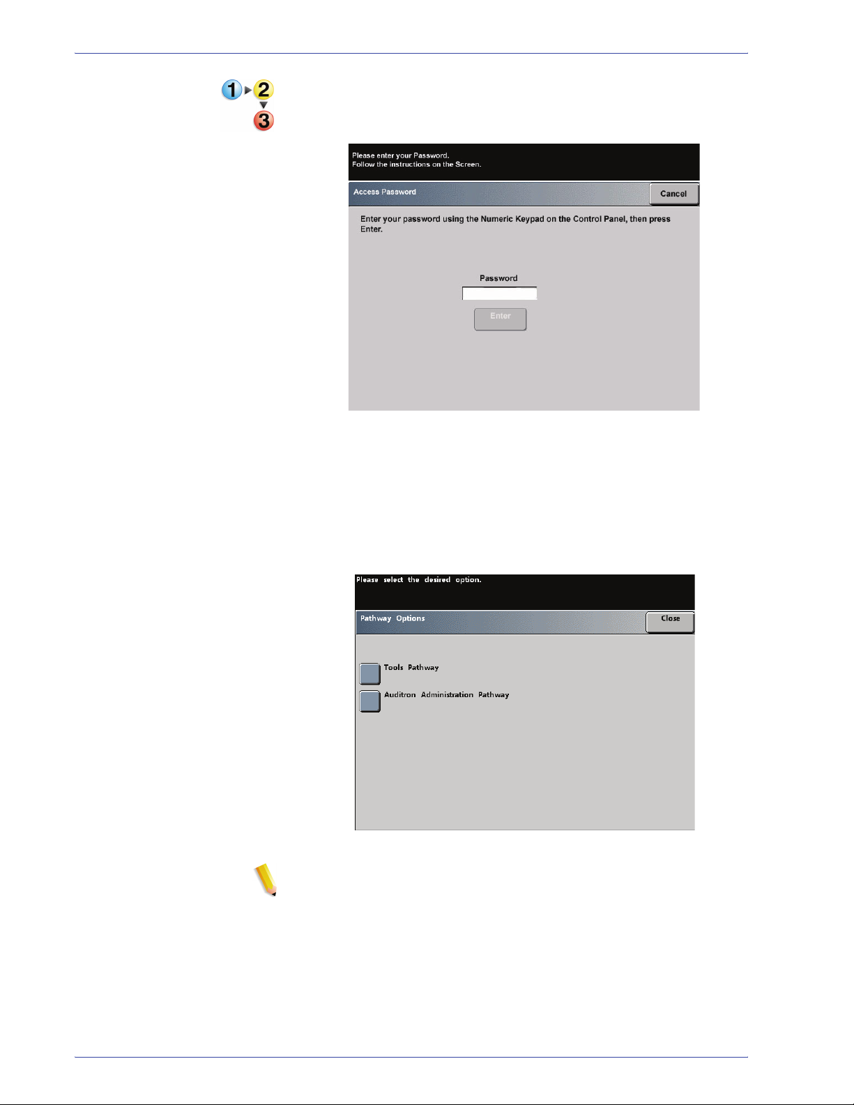
1. Press the Access button on the Control Panel. The Access
Password Screen appears.
2. Use the keypad to enter the Tools Mode password.
The default password is five ones (11111).
For security reasons, only asterisks are displayed on the
screen.
3. Touch the Enter button.
The Pathway Options screen appears.
1-2
NOTE: It is recommended that you change the Tools password as
soon as possible after installing the digital press in order to
prevent unauthorized access to the Tools Mode. The procedure
for changing the password is in Chapter 2 of this manual.
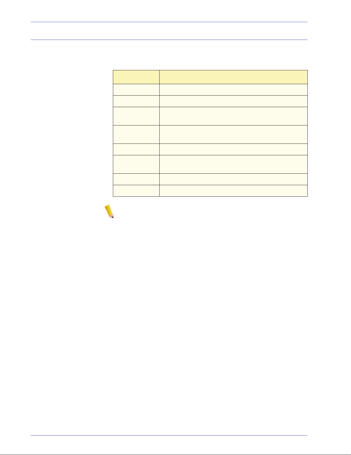
4. Touch the Tools Pathway button on the screen; you are now
in the Tools Mode.
5. To exit the Tools Mode, touch the Exit Tools button.
DocuColor 7000AP/8000AP System Administration Guide
Navigating in Tools Mode
Tabs Allows you to view the options available on that screen.
Enter Saves any changes you made on the screen.
System Default Returns the settings on the screen to the factory default
Close Closes the screen and returns the system to the
Off Deactivates the feature.
Reset Returns the settings on the screen to the settings that
Cancel Cancels the changes made on the screen.
1. Tools Mode
The following table tells you how to navigate in Tools Mode by
touching buttons.
Button Result
settings.
previous screen.
were in effect when the screen opened.
Exit Tools Exits the Tools Mode.
NOTE: Changes made to default settings in the Tools Mode take
effect when you exit Tools Mode.
DocuColor 7000AP/8000AP System Administration Guide
1-3
1. Tools Mode
Machine Defaults
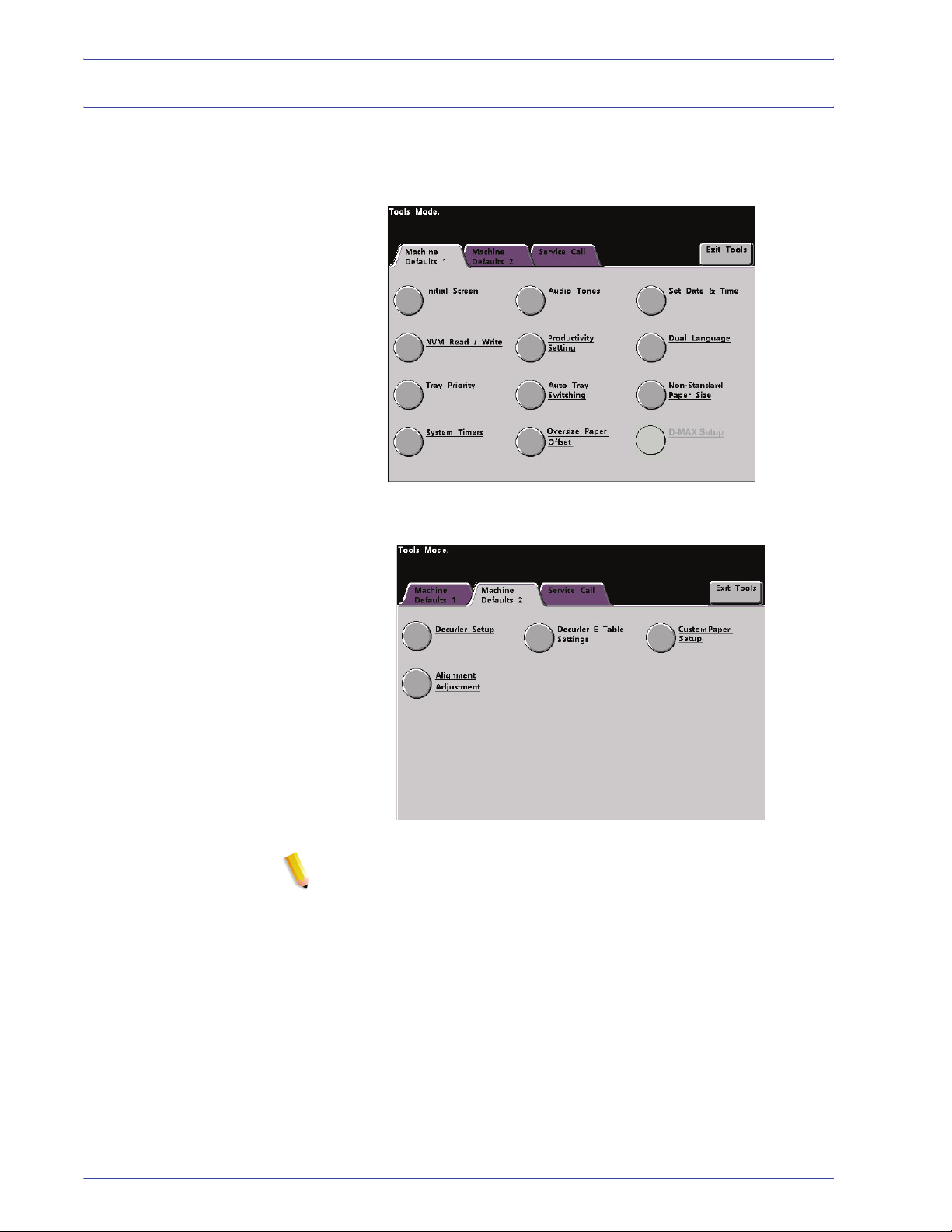
Two Machine Defaults screens are available for changing default
settings. Each of the features shown on the below screen is
described throughout the remainder of this chapter.
1-4
NOTE: The Service Call feature is not available.
DocuColor 7000AP/8000AP System Administration Guide
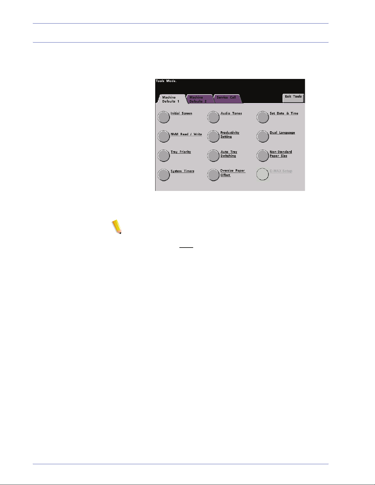
Machine Defaults 1
1. Tools Mode
This section describes the default settings available to you on the
Machine Defaults 1 screen and include the following (as shown in
the illustration):
The default settings procedures on the following pages are
accessed from The Machine Defaults 1 screen.
NOTE: The D-MAX Setup feature may or may not be selectable
with your DocuColor 7000AP/8000AP Digital Press
configuration. In either case, this feature is for the Xerox Service
Representative only
and is not for customer use.
DocuColor 7000AP/8000AP System Administration Guide
1-5
1. Tools Mode
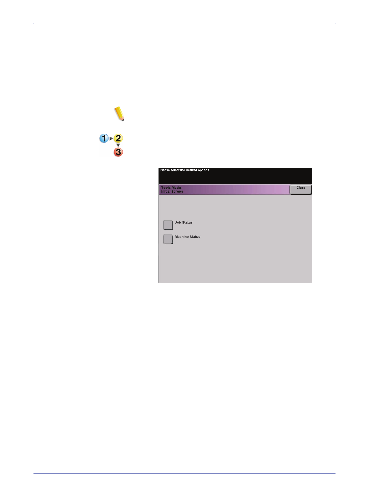
Initial Screen
Use the Initial Screen to select the screen that displays when the
digital press is powered on. You can choose from two screens:
• Job Status
• Machine Status
NOTE: The Machine Status screen is the factory default setting.
Use the following procedure to change the default initial screen.
1. Touch the Initial Screen button on the Machine Defaults 1
screen. The Initial Screen screen appears.
1-6
DocuColor 7000AP/8000AP System Administration Guide
1. Tools Mode
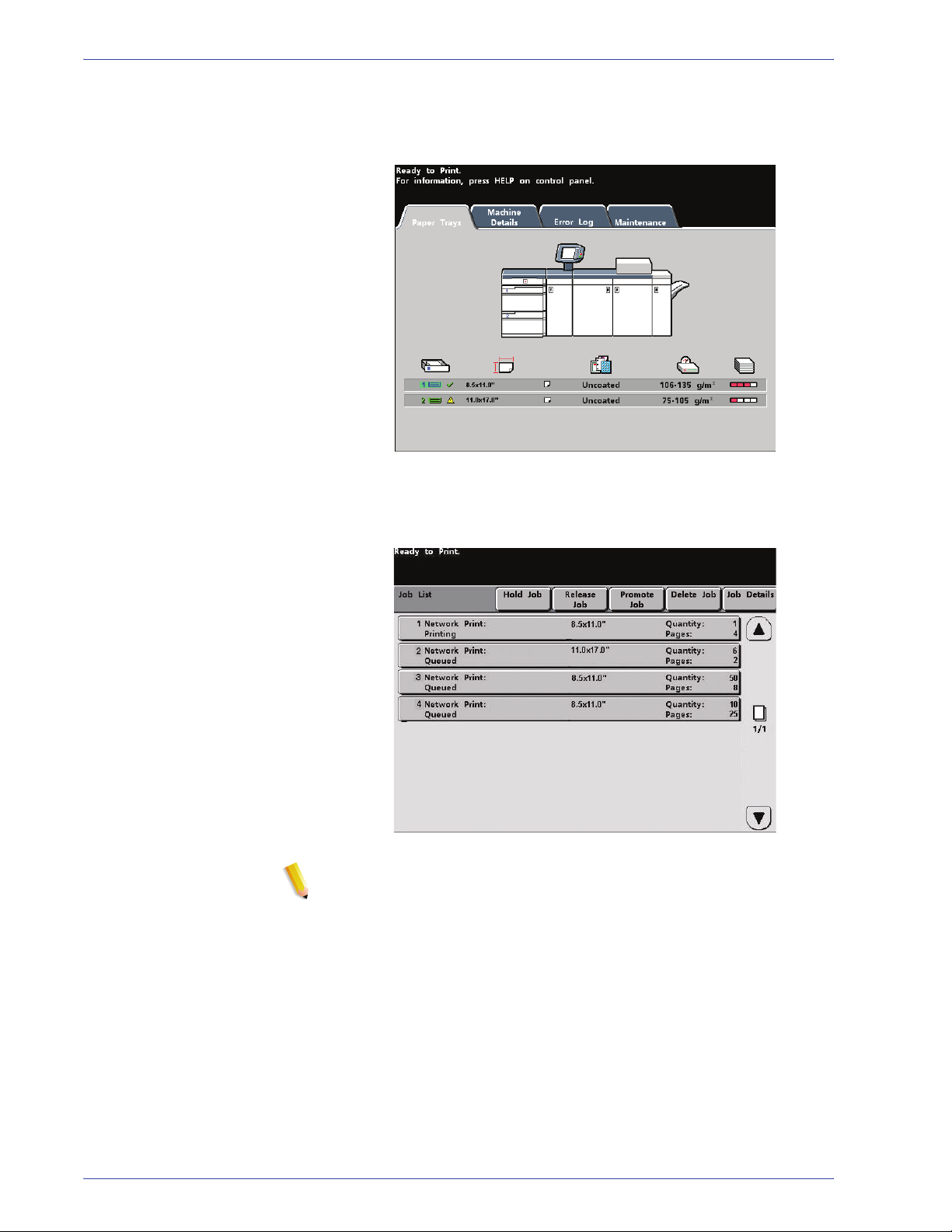
2. Touch the Machine Status or Job Status button.
If you select the Machine Defaults screen, the screen below
appears when the machine is powered on.
If you change the default setting to the Job Status screen, the
screen below appears when the machine is powered on. This
screen displays all the jobs currently queued for printing.
NOTE: Refer to the User Guide for more information about
the Machine Status and Job Status screens.
DocuColor 7000AP/8000AP System Administration Guide
1-7
1. Tools Mode
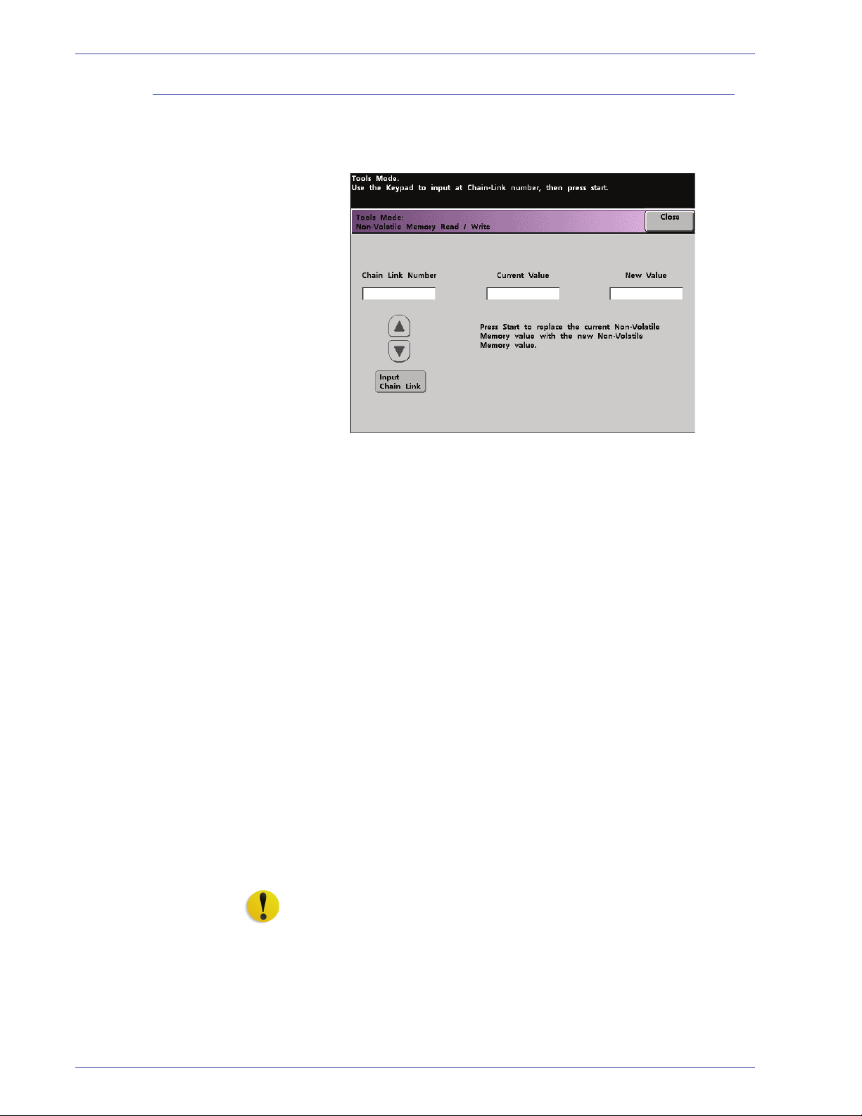
NVM Read/Write
Your Xerox service representative uses this feature to change
certain system settings. It also may occasionally be used by
system administrators.
Special Media Setting for
Drilled Papers
Special Media Setting for
LEF Tab Stock
Carbonless Media
Enablement
Under most conditions, this feature is not used by system
administrators; however, there are limited circumstances under
which this feature is used. These circumstances include:
If you use 3-hole, predrilled paper on a regular basis and
continually encounter an inordinate amount of paper jams, and/or
If you regularly run tab stock and continually encounter paper
jams.
• Carbonless papers are coated with several functional coatings
which promote the image transfer through the form set and
enable the form sets to separate appropriately after padding
with a special adhesive. Each supplier of xerographic
carbonless paper has developed their own unique chemistry,
which is why the following procedure enabling this application,
works best with Xerox Premium Digital Carbonless Paper.
• In order to avoid problems when running carbonless media,
you may use the NVM Read/Write feature to switch on the
carbonless media feature.
If any of the above conditions exist in your environment, you may
use the NVM Read/Write feature to swich on a feature.
1-8
CAUTION: Do not enter any numbers on this screen other than
the ones described in this procedure. Entering and saving
numbers, other than the ones described, changes the system
settings which may result in a service call to restore the system to
the correct settings.
DocuColor 7000AP/8000AP System Administration Guide
1. Tools Mode
To s wit ch on a feature, perform the following:
1. From the NVM Read/Write screen, use the keypad on the
Control Panel and enter the Chain Link Number:
• The Chain Link Number for Special Media Setting for
Drilled Papers is 700 545.
• The Chain Link Number for Special Media Setting for LEF
Tab St o ck is 700 546.
• The Chain Link Number for Carbonless Media Enablement
is 700-920.
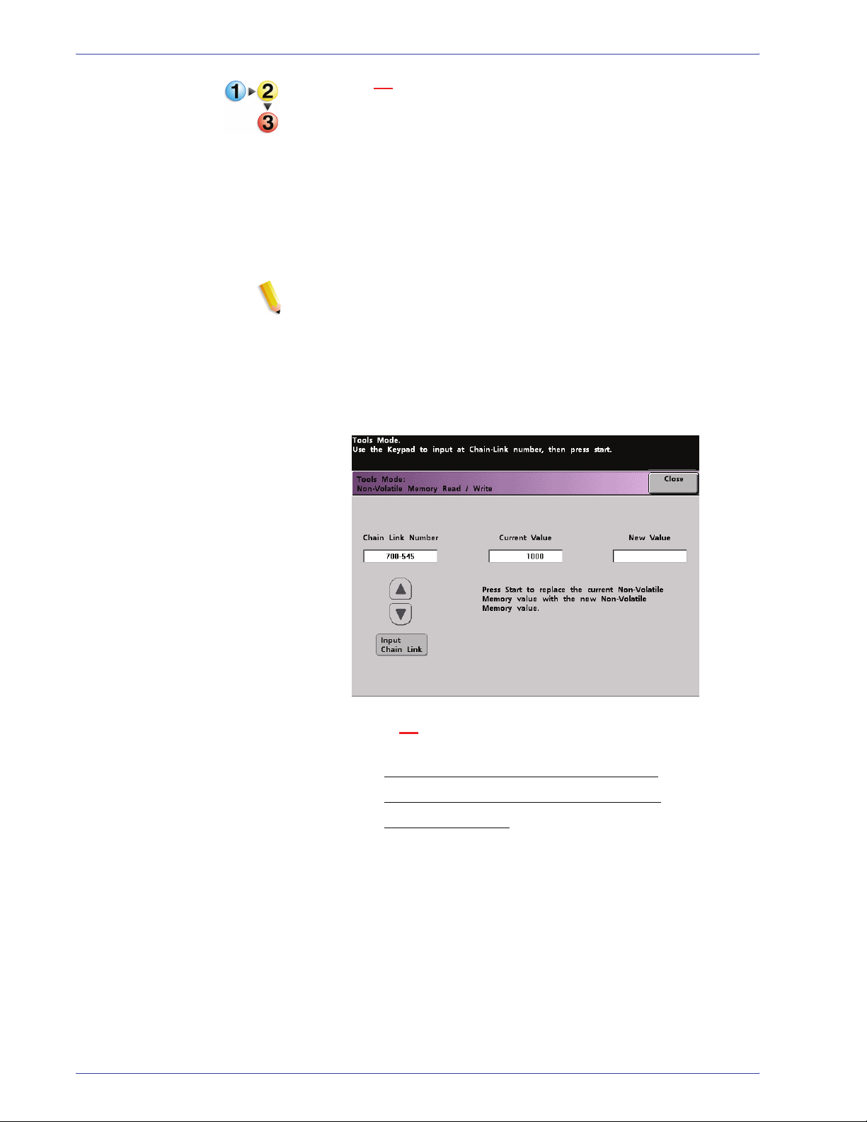
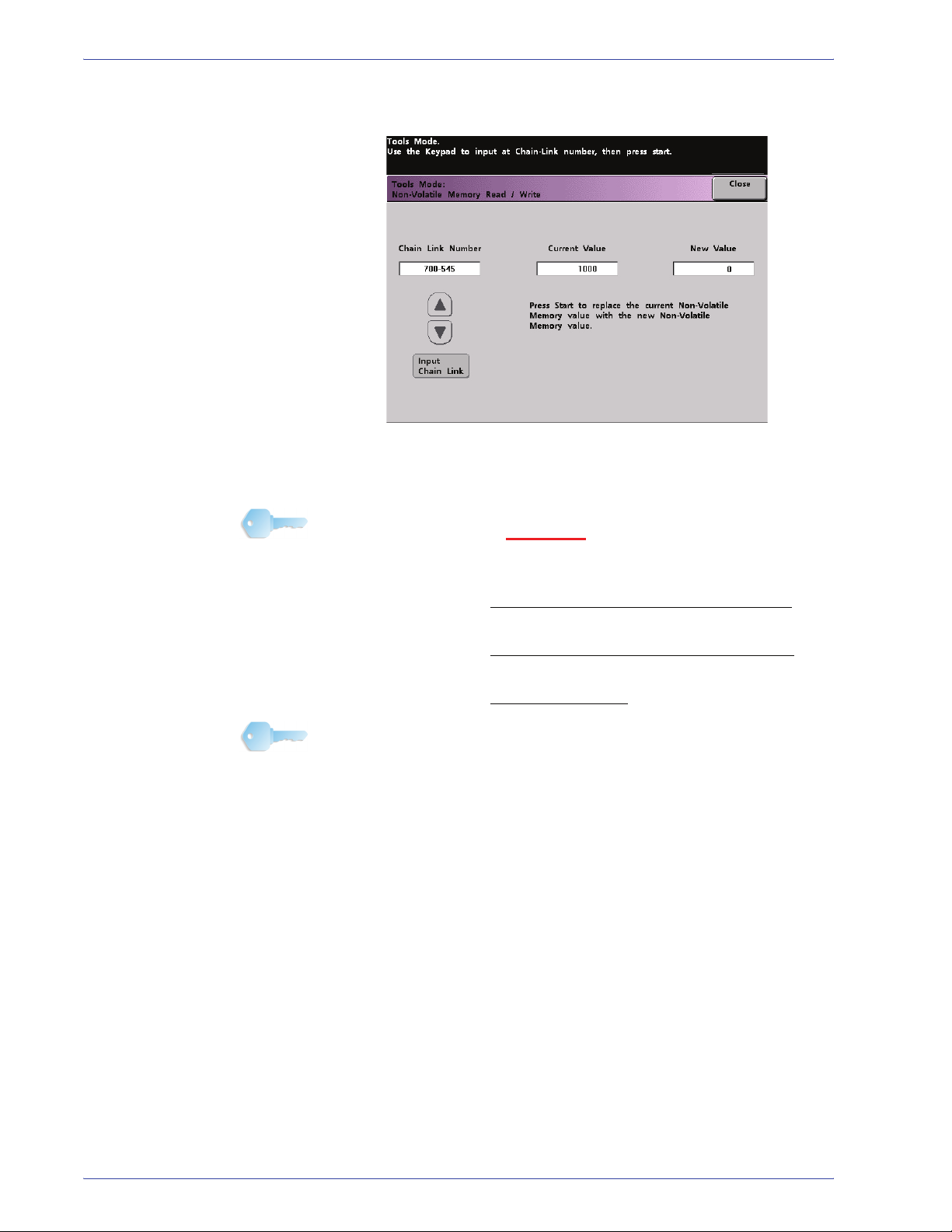
NOTE: For the purpose of this procedure, the following
screens show the Chain Link Number , Current V alue, and New
Value for Speci al Media Setting for Drilled Papers. The
Current Value and New Value numbers will vary depending on
the Chain Link Number entered.
2. After entering the desired Chain Link Number, press the Start
button on the Control Panel. The UI displays this screen:
3. To switch on
a feature, press the appropriate button on the
Control Panel keypad:
• For Special Media Setting for Drilled Papers
• For Special Media Setting for LEF Tab Stock
• For Carbonless Media
DocuColor 7000AP/8000AP System Administration Guide
, press 0.
, press 1.
, press 1.
1-9
1. Tools Mode
4. After entering the New Value number, press the Start
button. The UI displays the following screen:
5. Touch the Close button to save and close your new setting.
6. Exit Tools Mode and run your print job.
KEY POINT 1: After running your print job, reenter Tools Mode,
NVM Read/Write, and switch off
the feature that is currently
on. Follow the steps outlined in this procedure and use these
settings for the New Value number:
• To switch off the Special Media Setting for Drilled Papers
,
enter 1000.
• To switch off the Special Media Setting for LEF Tab Stock
,
enter 0.
• To switch off the Carbonless Media
, enter 0.
KEY POINT 2: To prevent paper jams from occurring with stock
types other than the ones mentioned in this procedure, you must
switch off the NVM Read/Write feature before running other print
jobs.
1-10
DocuColor 7000AP/8000AP System Administration Guide
Tray Priority
1. Tools Mode
Select the priority order for each paper tray. If the Auto Tray
Switching feature is enabled and each paper tray contains the
same paper size and weight, the digital press feeds paper from
the tray set at Priority 1. If there is no paper in the Priority 1 tray,
the Priority 2 tray is automatically selected and so on.
Use the following procedure to set the priority for each paper tray.
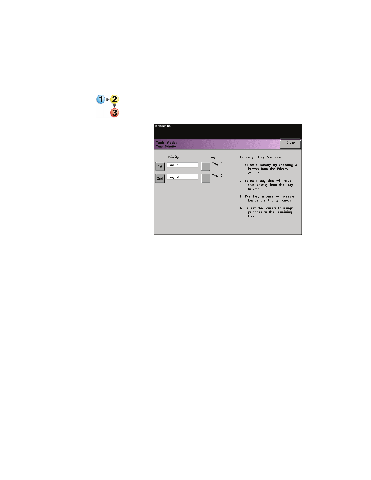
1. Touch the Tray Priority button on the Machi ne De faults 1
screen. The Tray Priority screen appears.
2. Touch the desired Priority button in the Priority column.
3. Touch the button for the Paper Tray that will have that priority.
The number of the selected Paper Tray appears next to that
Priority button.
4. Repeat this procedure for each Priority. You cannot set the
same paper tray for more than one Priority at a time.
5. Touch the Close button to return to the Machine Defaults 1
screen. You cannot touch the Close button until you set paper
trays for each Priority.
DocuColor 7000AP/8000AP System Administration Guide
1-11
1. Tools Mode
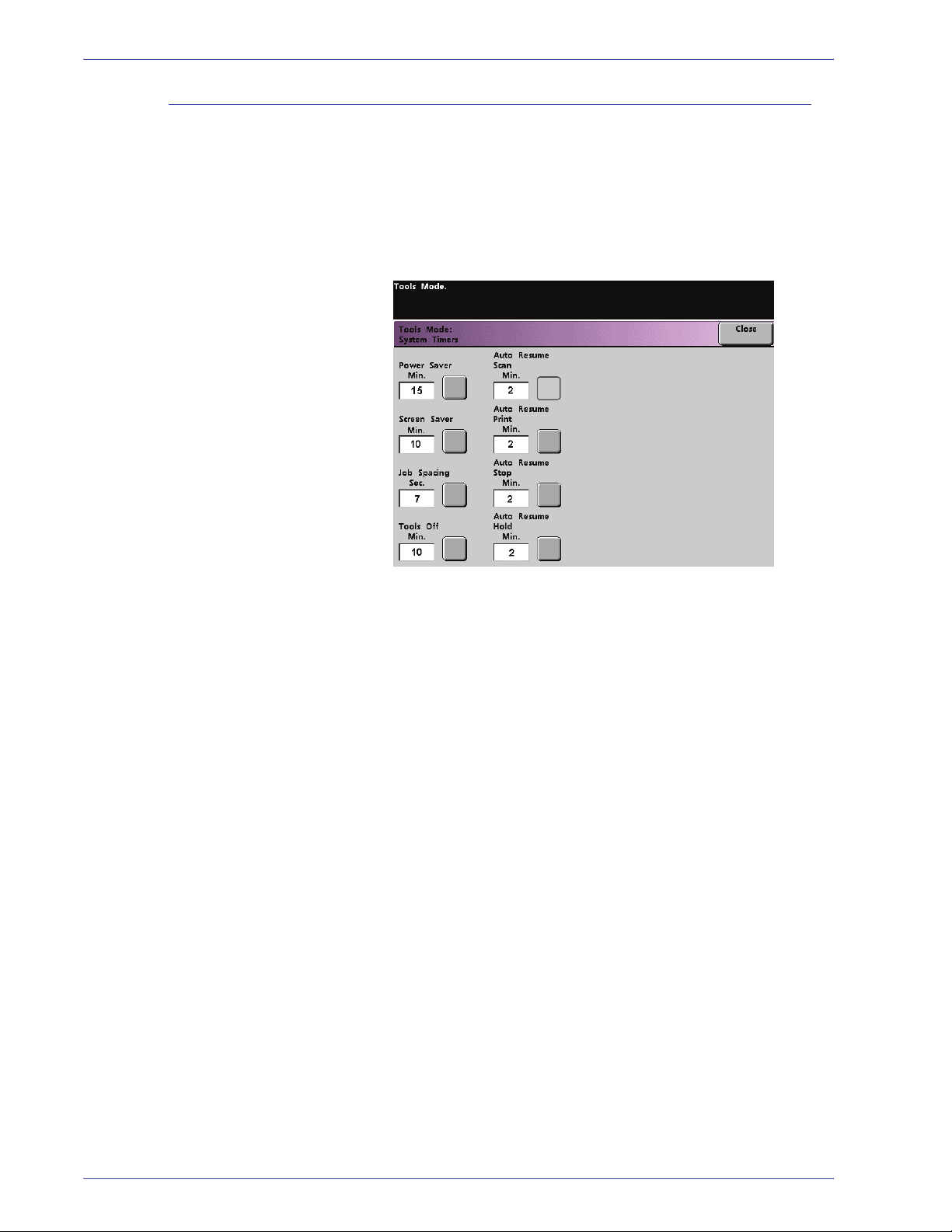
System Timers
Use this feature to change the factory default settings for the
timers in the digital press. To access the various timers, touch the
System Timers button on the Machine Defaults 1 screen.
The System Timers screen appears. From this screen you can
view the time currently set for each of the timers, and select the
one you want to change.
1-12
DocuColor 7000AP/8000AP System Administration Guide

Power Save r
Use this feature to set the time that elapses until the digital press
enters a reduced power consumption mode. This timer is
activated when all print jobs have been completed and there are
no jobs in the job queue.
The digital press exits the Power Saver mode when a job is sent to
be printed or the Touch Screen is activated
1. Touch the Power Saver button on the System Timers screen.
1. Tools Mode
2. Use the up or down arrow buttons to change the time. The
range available is one to 240 minutes.
To use the system default time of fifteen minutes, touch the
System Default button.
3. Touch the Enter button on the screen to enter the new time
into the system.
4. Touch the Close button to return to the Machine Defaults 1
screen or to select another timer to change.
DocuColor 7000AP/8000AP System Administration Guide
1-13
1. Tools Mode
Screen Saver
The Screen Saver feature allows you to protect the screen from
being damaged with permanent marks if the digital press is idle for
a period of time.
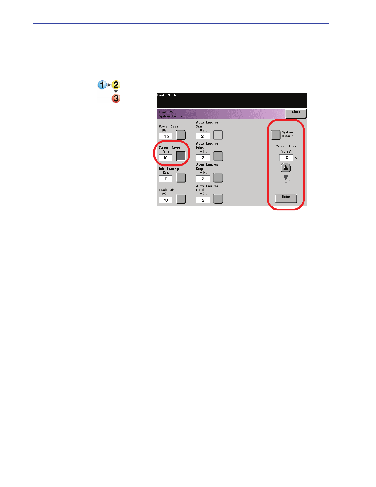
1. Touch the Screen Saver button on the System Timers screen.
2. Use the up or down arrow buttons to change the time. The
range available is ten to sixty minutes.
To use the system default time of ten minutes, touch the
System Default button.
3. Touch the Enter button on the screen to enter the new time
into the system.
4. Touch the Close button to return to the Machine Defaults 1
screen or select another timer to change.
1-14
DocuColor 7000AP/8000AP System Administration Guide
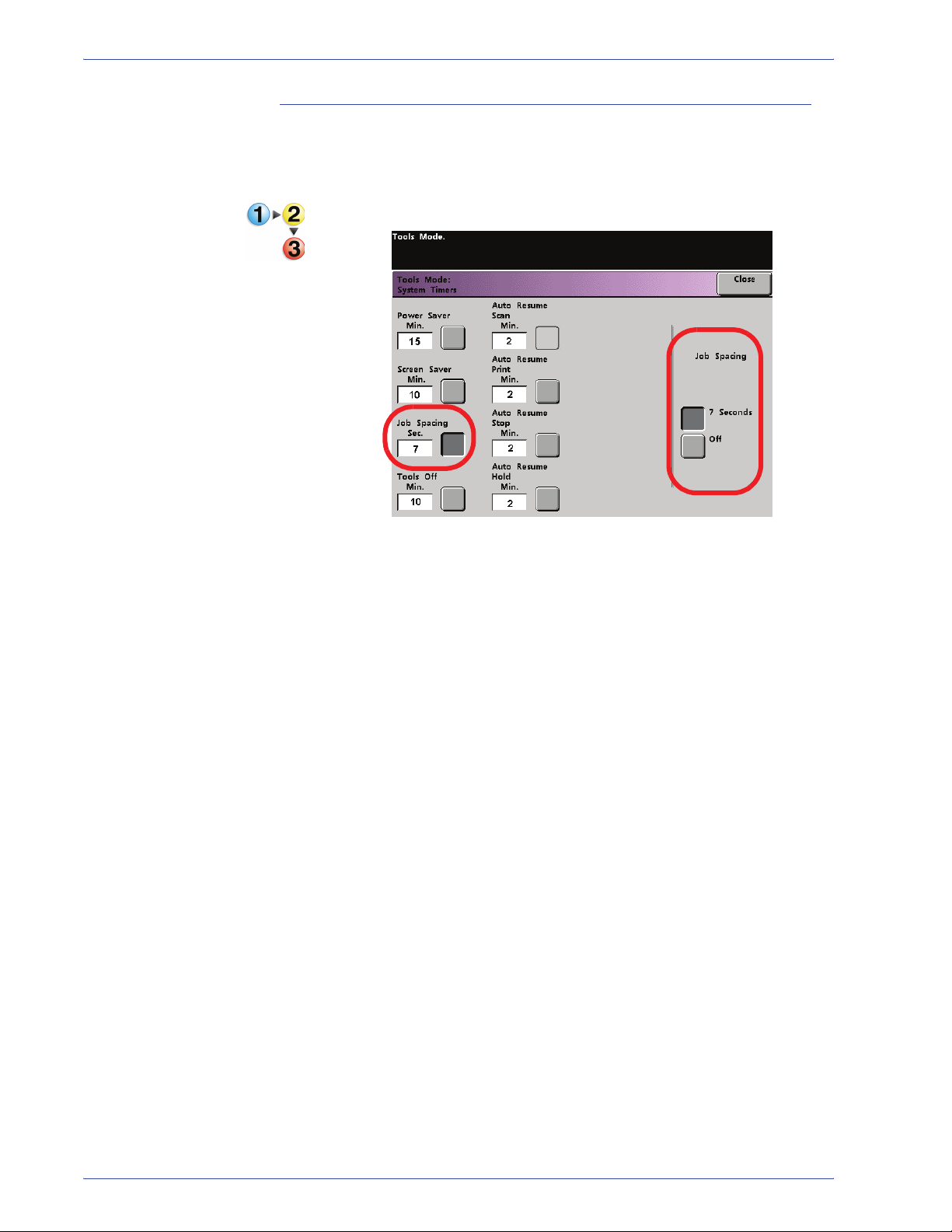
Job Spacing
Use the Job Spacing feature when there are multiple jobs queued
and you would like to allow seven seconds to unload prints from a
finishing device before the next job starts printing.
1. Touch the Job Spacing button on the System Timers screen.
1. Tools Mode
2. Touch the 7 Seconds button to enable the feature or touch the
Off button to disable the feature.
3. Touch the Close button to return to the Machine Defaults 1
screen or select another timer to change.
DocuColor 7000AP/8000AP System Administration Guide
1-15
1. Tools Mode
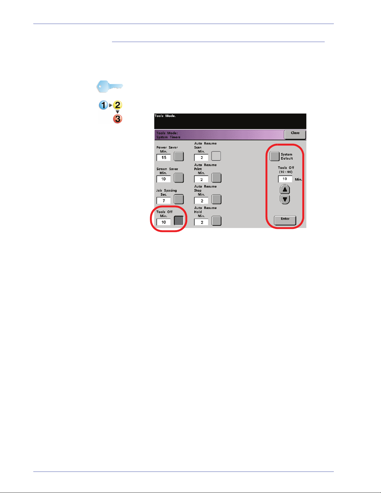
Tools Off
Use the Tools Off feature to have the digital press automatically
return to the printing mode when no action is taken on the Tools
Mode screens after the set amount of time.
KEY POINT: Jobs sent over the network will queue but will not
print while the Tools Mode is active.
1. Touch the Tools Off button on the System Timers screen.
2. Use the up or down arrow buttons to change the time. The
range available is ten to sixty minutes.
To use the system default time of ten minutes, touch the
System Default button.
3. Touch the Enter button on the screen to enter the new time
into the system.
4. Touch the Close button to return to the Machine Defaults 1
screen or select another timer to change.
1-16
DocuColor 7000AP/8000AP System Administration Guide
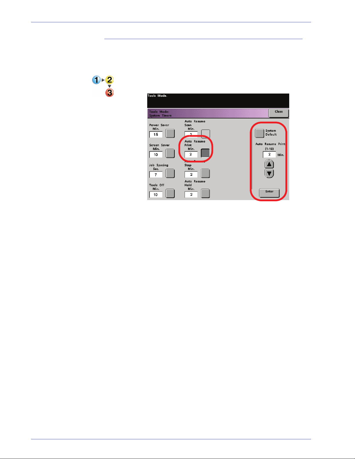
Auto Resume Print
Use the Auto Resume Print feature to restart a job automatically
after a fault is cleared and a job received over the network is
waiting for user instruction.
1. Touch the Auto Resume Print button on the System Timers
screen.
1. Tools Mode
2. Use the up or down arrow buttons to change the time. The
range available is one to ten minutes.
To use the system default time of two minutes, touch the
System Default button.
3. Touch the Enter button on the screen to enter the new time
into the system.
4. Touch the Close button to return to the Machine Defaults 1
screen or select another timer to change.
DocuColor 7000AP/8000AP System Administration Guide
1-17
1. Tools Mode
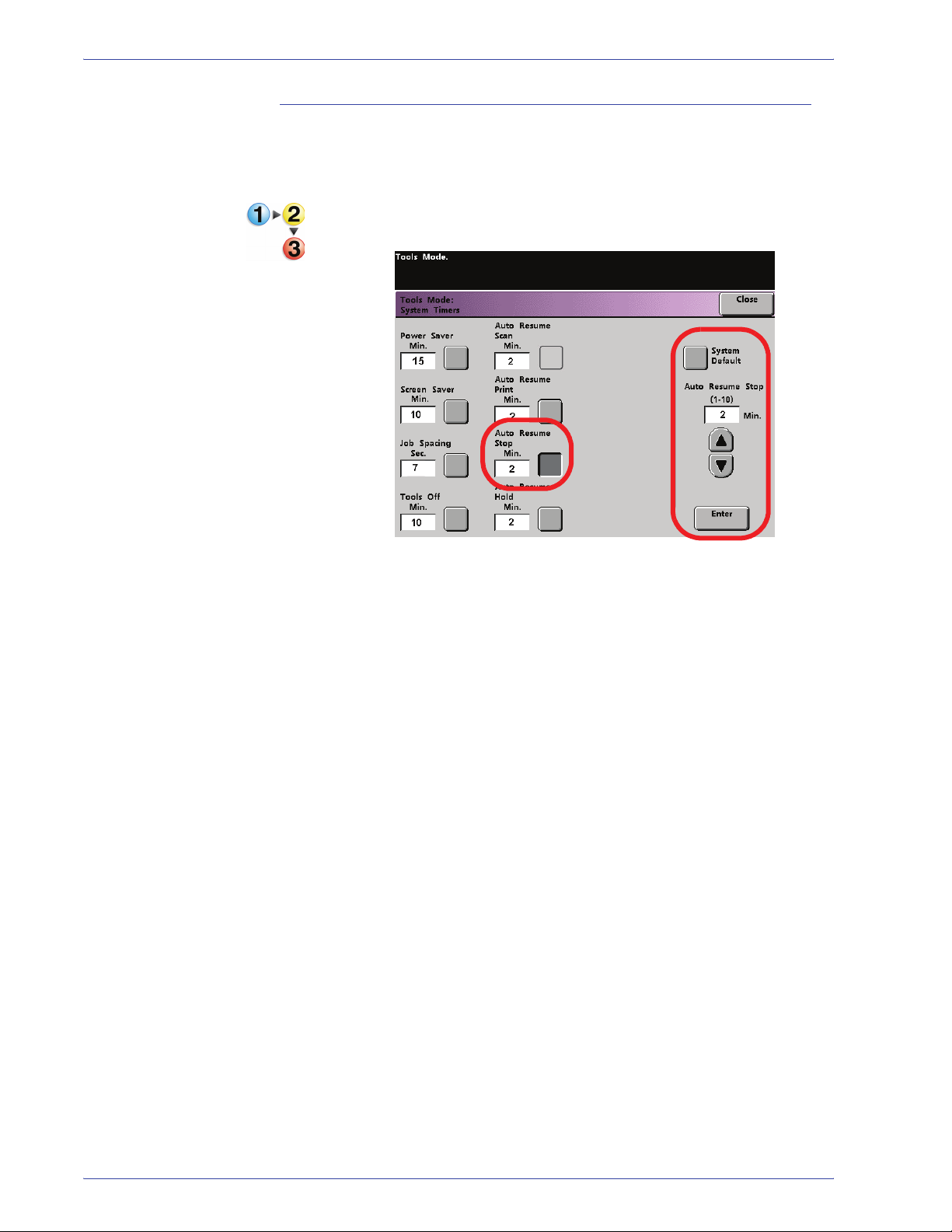
Auto Resume Stop
Use the Auto Resume Stop feature to restart a job automatically
after the Pause button on the Control Panel is pressed and the job
is waiting for user instruction.
1. Touch the Auto Resume Stop button on the System Timers
screen.
2. Use the up or down arrow buttons to change the time. The
range available is one to ten minutes.
To use the system default time of two minutes, touch the
System Default button.
3. Touch the Enter button on the screen to enter the new time
into the system.
4. Touch the Close button to return to the Machine Defaults 1
screen or select another timer to change.
1-18
DocuColor 7000AP/8000AP System Administration Guide
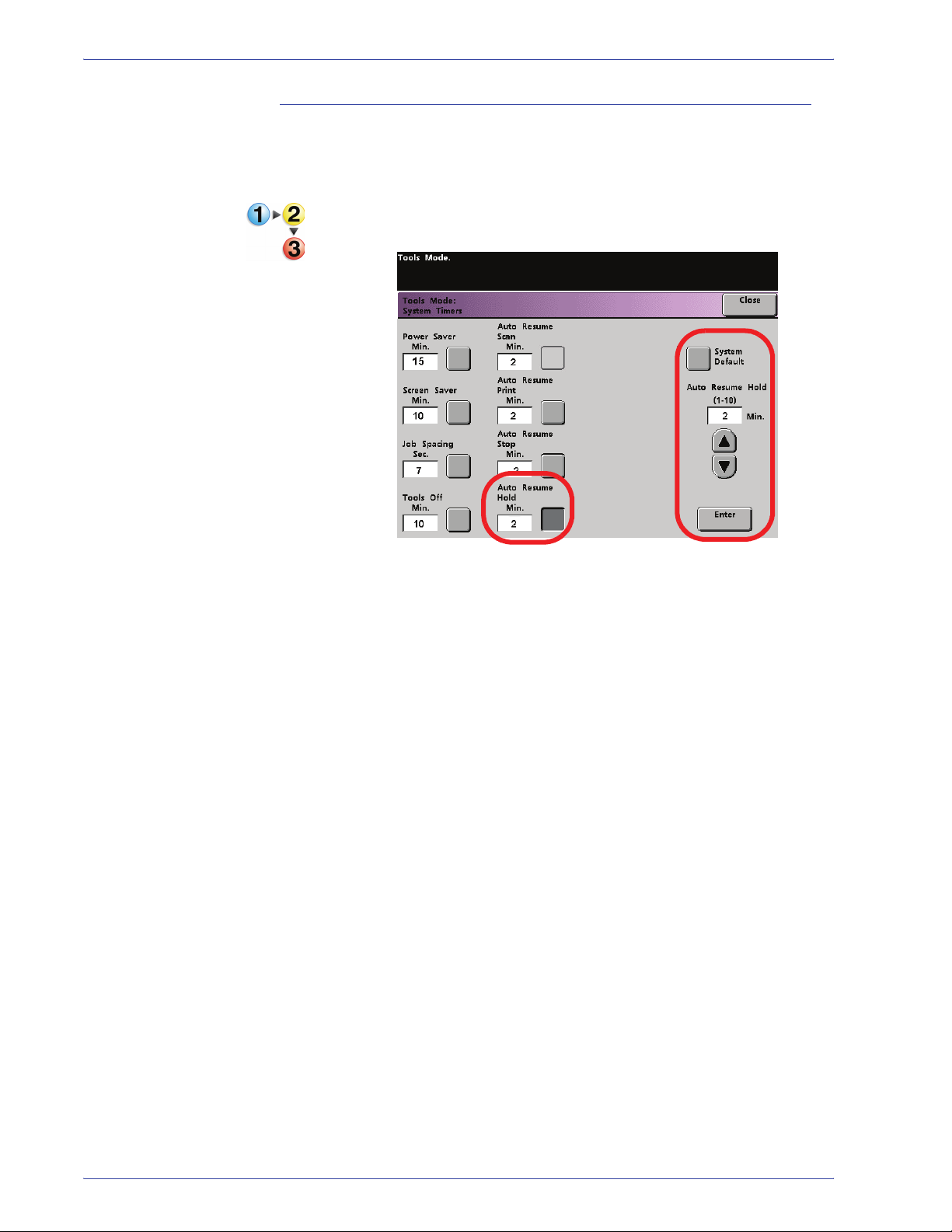
Auto Resume Hold
Use the Auto Resume Hold feature to automatically print the next
job in the queue if the current job is waiting for user instruction to
clear a certain type of fault.
1. Touch the Auto Resume Hold button on the System Timers
screen.
1. Tools Mode
2. Use the up or down arrow buttons to change the time. The
range available is one to ten minutes.
To use the system default time of two minutes, touch the
System Default button.
3. Touch the Enter button on the screen to enter the new time
into the system.
4. Touch the Close button to return to the Machine Defaults 1
screen or select another timer to change.
DocuColor 7000AP/8000AP System Administration Guide
1-19
1. Tools Mode
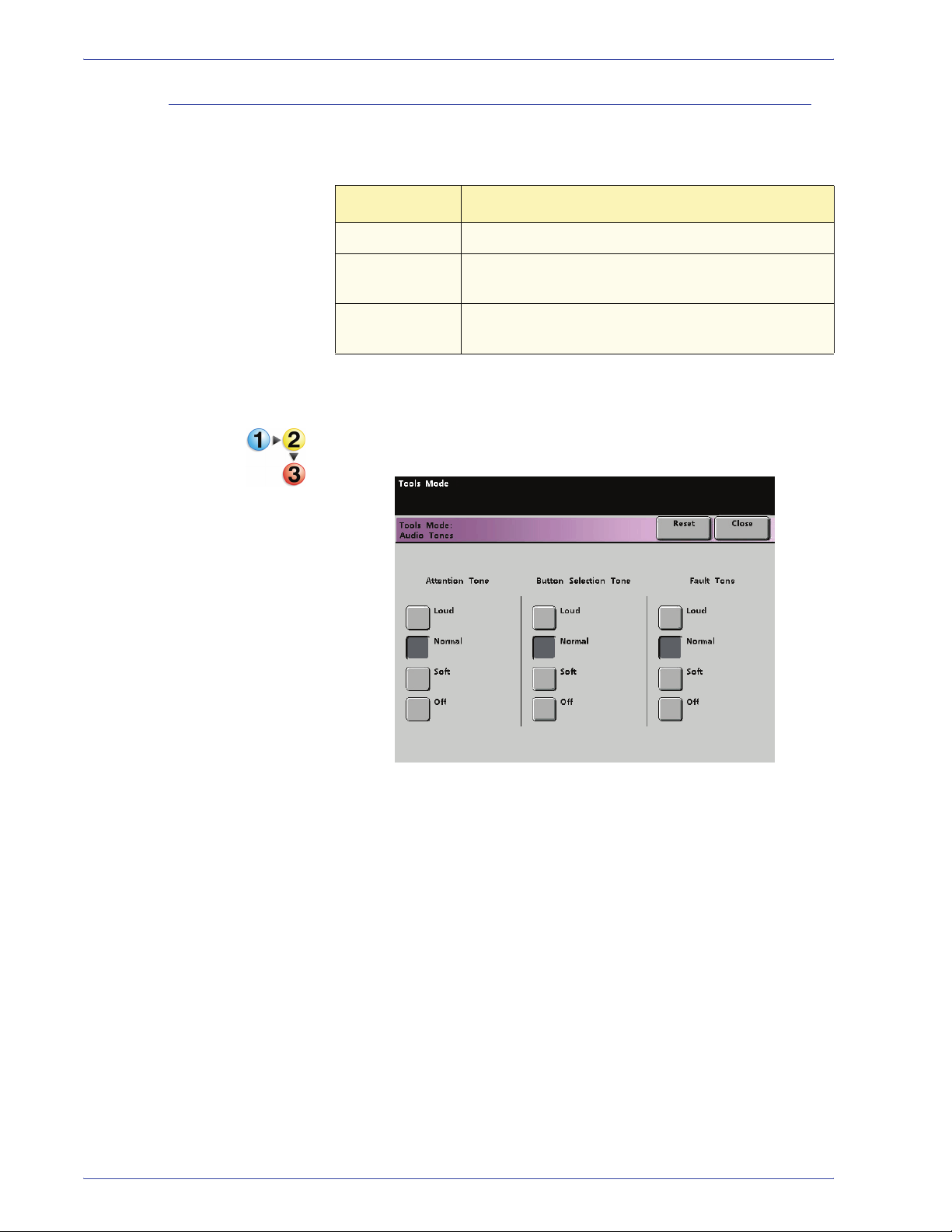
Audio Tones
There are three types of audio tones that can be activated on the
digital press, as shown in the following table.
Tone What the Tone Indicates
Attention Tone An unselectable button has been touched.
Button
Selection Tone
Fault Tone The press is in a fault condition and cannot
A selectable button has been touched.
continue printing.
Each of these tones can be deactivated or set to Soft, Normal, or
Loud. The factory default setting is Normal.
1. Touch the Audio Tones button on the Machine Defaults 1
screen.
1-20
2. Touch the button for the desired volume setting for each tone.
To deactivate a tone, touch the Off button for that tone.
3. Touch the Reset button to restore the factory default setting for
the three tones.
4. Touch the Close button to return to the Machine Defaults 1
screen.
DocuColor 7000AP/8000AP System Administration Guide
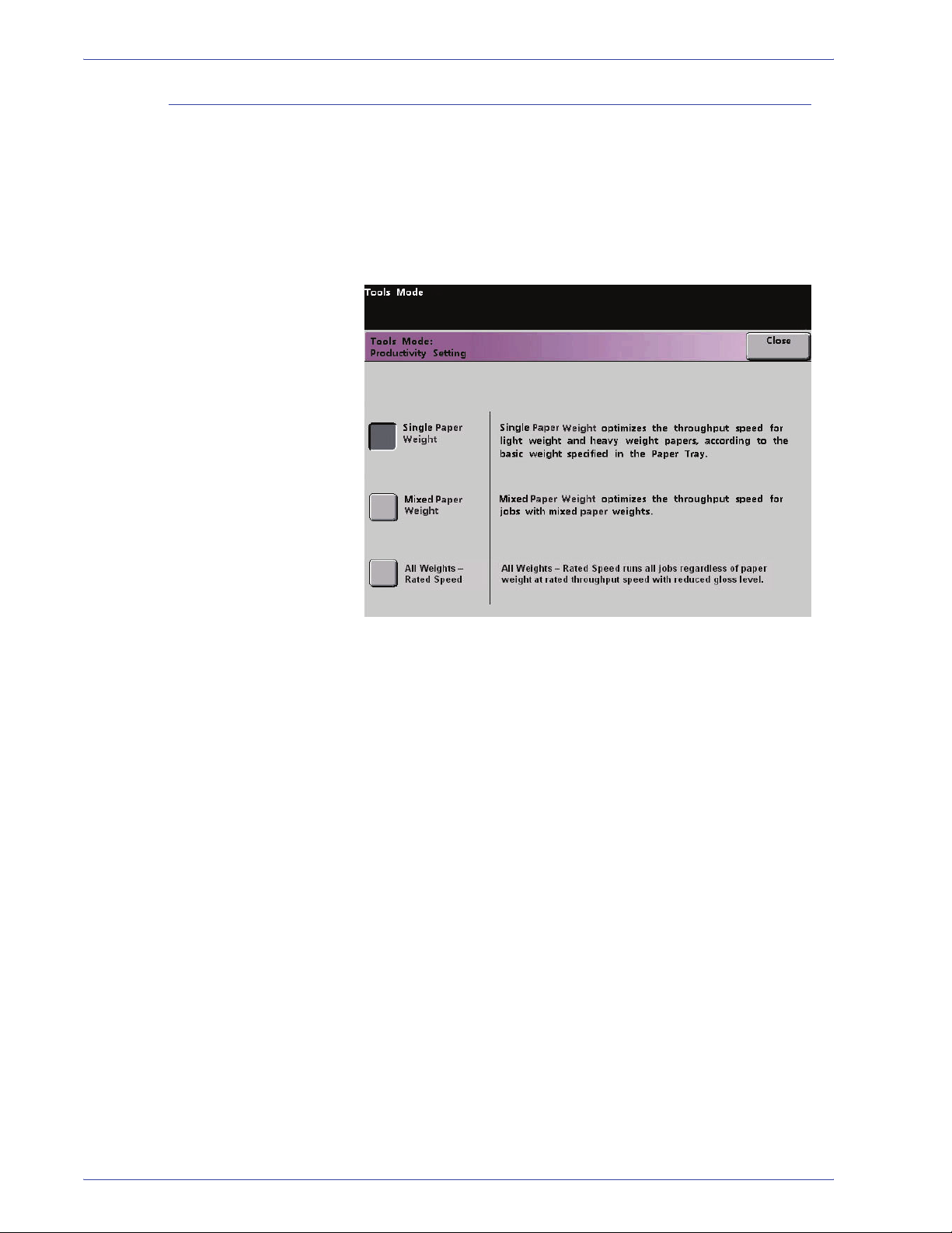
Productivity Setting
1. Tools Mode
The productivity of the digital press relates to the continuous
speed of the media output as measured in prints per minute
(ppm). The continuous speed is dependent on paper size, paper
weight, and fuser temperature.
Use this setting to optimize the throughput speed for the type of
paper you run most frequently. Productivity Setting options are
shown and explained in the following illustration:
Single Paper Weight: This setting optimizes the throughput speed for light weight or
heavy weight papers, according to the weight range that is set in
the paper tray.
Mixed Paper Weight This setting optimizes the throughput speed of print jobs that
contain mixed media weights from different paper trays.
All Weights Rated Speed This setting allows all print jobs to run at the same, or rated,
throughput speed, regardless of weight. The digital press
produces/prints images with a reduced level of gloss on the
output.
DocuColor 7000AP/8000AP System Administration Guide
1-21
1. Tools Mode
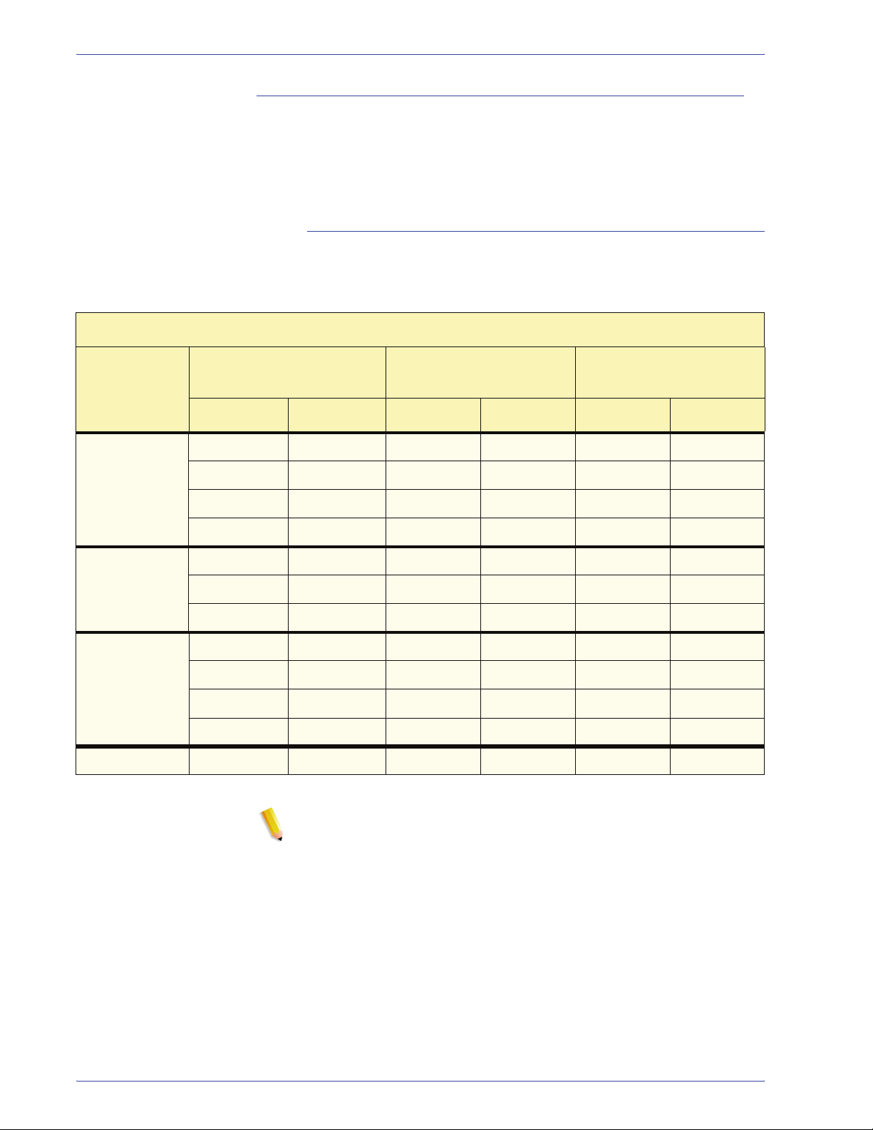
Productivity charts
The following productivity charts lists the various paper weights
and sizes and their related print speeds for 1 Sided and 2 Sided
output. Each chart outlines the print speed parameters for both
productivity settings.
Single Paper Weight
Single Paper Weight Mode
Paper Size(Feed direction
Paper Weight
60 - 135 g/m
136 - 220 g/m
221 - 300 g/m
Transparency 210.0 216.0 30 - 30 -
2
2
2
length)[mm]
Min. Max 1 Sided 2 Sided 1 Sided 2 Sided
182.0 216.0 80 40 70 35
216.1 297.0 60 30 60 30
297.1 458.0 40 20 35 17.5
458.1 488.0 30 15 30 15
182.0 216.0 60 30 50 25
216.1 450.0 30 15 25 12.5
450.1 488.0 20 10 15 7.5
182.0 216.0 40 - 35 -
216.1 280.0 30 - 30 -
280.1 458.0 20 - 15 -
458.1 488.0 10 - 10 -
Print Speed for
DocuColor 8000AP
Print Speed for
DocuColor 7000AP
1-22
NOTE 1:2-Sided printing is not available for transparency and
paper that is 221 g/m
2
or greater.
NOTE 2:There is no decrease in productivity (ppm) from the
second feeder module to the first feeder module.
NOTE 3:Transparency is only available for 1 Sided, A4 or 8.5” x
11” LEF.
DocuColor 7000AP/8000AP System Administration Guide
Mixed Paper Weight
Mixed Paper Weight Mode
1. Tools Mode
Paper Weight
60 - 105 g/m
106 - 135 g/m
136 - 186 g/m
187 - 220 g/m
Paper Size(Feed
direction length)[mm]
Min. Max Simplex Duplex Simplex Duplex
2
182.0 216.0 80 40 70 35
216.1 297.0 60 30 60 30
297.1 458.0 40 20 35 17.5
458.1 488.0 30 15 30 15
2
182.0 216.0 60* 30 60* 30
216.1 450.0 30* 15* 30* 15*
450.1 488.0 20* 10* 20* 10*
2
182.0 216.0 60* 30 50* 25
216.1 450.0 30* 15* 25* 12.5*
450.1 488.0 20* 10* 15* 7.5*
2
182.0 216.0 40 20 40 20
216.1 280.0 30 15 30 15
Print Speed for
DocuColor 8000AP
Print Speed for
DocuColor 7000AP
280.1 458.0 20 10 20 10
458.1 488.0 10 5 10 5
221 - 300 g/m
2
182.0 216.0 40* -- 35* --
216.1 280.0 30* -- 30* --
280.1 458.0 20* -- 15* --
458.1 488.0 10* -- 10* --
Transparency 210.0 216.0 30 -- 30 --
NOTE: *Print speeds may decrease due to printer setup
operations, which are based on environment al conditions and
specific interval volume of continuous printing.
DocuColor 7000AP/8000AP System Administration Guide
1-23
1. Tools Mode
All Weights Rated Speed
All Weights Rated Speed Mode
Paper Weight
36 - 135 lb (60
- 220 g/m
136 - 184 lb
(221 - 300
2)
g/m
2)
Paper Size (Feed direction
length) [inches/mm]
Min. Max 1 Sided 2 Sided 1 Sided 2 Sided
7.16 in.
(182.0 mm)
8.51 in.
(216.1 mm)
11.7 in.
(297.1 mm)
18.1 in.
(458.1 mm)
7.16 in.
(182.0 mm)
8.51 in.
(216.1 mm)
11.7 in.
(297.1 mm)
8.5 in.
(216.0 mm)
11.69 in.
(297.0 mm)
18 in. (458.0
mm)
19.2 in.
(488.0 mm)
8.5 in.
(216.0 mm)
11.69 in.
(297.0 mm)
18 in. (458.0
mm)
Print Speed for
DocuColor 8000
(prints per minute = ppm)
80 40 70 35
60 30 60 30
40 20 35 17.5
30 15 30 15
80 - 70 -
60 - 60 -
40 - 35 -
Print Speed for
DocuColor 7000
(prints per minute = ppm)
Transparency
* Only available
for 1-Sided, 8.5
x 11 inch/A4 LEF
18.1 in.
(458.1 mm)
8.3 in.
(210.0 mm)
19.2 in.
(488.0 mm)
8.5 in (216.0
mm)
30 - 30 -
30 - 30 -
NOTE 1:2-Sided printing is not available for transparency and
paper that is 221 g/m
2
or greater.
NOTE 2:There is no decrease in productivity (ppm) from the
second feeder module to the first feeder module.
NOTE 3:Transparency is only available for 1 Sided, A4 or 8.5” x
11” LEF.
1-24
DocuColor 7000AP/8000AP System Administration Guide

Productivity Setting procedure
Use the following procedure for choosing the setting which is best
for your environment.
1. Touch the Productivity Setting button on the Machine
Defaults 1 screen.
1. Tools Mode
2. Select the button for the type of paper you use most frequently
in the digital press, either Single Paper Weight, Mixed Paper
Weight, or All Weights Rated Speed.
3. Touch Close to return to the M achine Defaults 1 screen.
DocuColor 7000AP/8000AP System Administration Guide
1-25

1. Tools Mode
Auto Tray Switching
This feature allows you to set the default settings for the following
options:
Default Setting What the Default Does
Auto Tray Switching
(ATS)
Auto Paper Selection
(APS)
Inhibited Tray Allows you to select a specific paper tray, or trays, that you want the digital press to
Allows the digital press to automatically select another paper tray, containing the
appropriate paper, if the selected paper tray becomes unusable
Allows the digital press to automatically select the appropriate paper size for the
job being processed, without a specific paper tray being selected
bypass, regardless of the Tray Priority settings
1. Touch the Auto Tray Switching button on the Machine
Defaults 1 screen.
1-26
2. Touch the Enable or Disable button for the Auto Tray
Switching option.
3. Touch the Enable or Disable button for the Auto Paper
Selection option.
4. To instruct the digital press to bypass one or more of the paper
trays, touch the desired Paper Tray button in the Inhibited Tray
column.
• To deselect a paper tray, touch that Paper Tray button
again.
• To return the settings to the last saved values, touch the
Reset button.
5. Touch the Close button to return to the Machine Defaults 1
screen.
DocuColor 7000AP/8000AP System Administration Guide

Oversize Paper Offset
Use this feature for media that is larger than long edge feed,
8.5x11 inch/A4 paper, such as 12 x 18 in. (304.8 x 457.2 mm).
NOTE: Some color server manufacturers have an oversize paper
offset feature that you can also use to adjust the position of the
image on the paper. Refer to the documentation that came with
your color server.
Use the following procedure to adjust the registration on paper
that is larger than 8.5 x 11 in./A4.
1. Select the Oversize Paper Offset feature.
2. From the Oversize Paper Offset screen, select the desired
1. Tools Mode
Oversize Paper Offset button to adjust the registration on
paper larger than 8.5x11 inch or A4 LEF.
The table on the following page defines each offset level.
DocuColor 7000AP/8000AP System Administration Guide
1-27

1. Tools Mode
3. Touch the Offset Level 1, 2, 3, or 4 button to adjust the
position of the paper as it feeds. Refer to the following table for
the adjustments made for each Offset Level.
Paper Size Level 1 Level 2 Level 3 Level 4
310mm 10.0mm 10.0mm 10.0mm 10.0mm
311mm 9.5mm 9.5mm 9.5mm 9.5mm
312mm 9.0mm 9.0mm 9.0mm 9.0mm
313mm 8.5mm 8.5mm 8.5mm 8.5mm
314mm 8.0mm 8.0mm 8.0mm 8.0mm
315mm 7.5mm 7.5mm 7.5mm 8.0mm
316mm 7.0mm 7.0mm 7.0mm 8.0mm
317mm 6.5mm 6.5mm 7.0mm 8.0mm
318mm 6.0mm 6.0mm 7.0mm 8.0mm
319mm 5.5mm 6.0mm 7.0mm 8.0mm
320mm 5.0mm 6.0mm 7.0mm 8.0mm
The following illustration demonstrates how the image is
shifted on the paper after selecting an Oversize Paper Offset
level.
Image is
shifted away
from the edge
of the paper.
This dimension
increases
with higher
offset values.
Image
Paper
Lead edge
of paper
1-28
DocuColor 7000AP/8000AP System Administration Guide

Set Date & Time
Setting the Date
1. Tools Mode
Use this feature to set the date and time for the system. The date
and time is displayed on the Er ror Log screen and on the Date and
Time screens.
1. Touch the Set Date & Time button on the Machine Defaults 1
screen. The Set Date and Time screen appears with the Set
Date button selected and options for setting the date displayed
on the right.
2. Select the date format you wish to use.
3. Use the up or down arrow buttons to enter the correct year,
month, and day.
4. Touch the Enter button on the screen to save your selections.
The next time you enter the Tools Mode, the date that you set
is displayed.
DocuColor 7000AP/8000AP System Administration Guide
1-29

1. Tools Mode
Setting the Time
1. Touch the Set Date & Time button on the Machine Defaults 1
screen. The Set Date and Time screen appears with the Set
Date button selected and options for setting the date displayed
on the right.
2. Touch the Set Ti me button. Options for setting the time appear
in the Set Time screen.
3. Touch the 12 Hour Clock or the 24 Hour Clock button.
4. Use the up or down arrow buttons to set the correct hour and
minutes.
If you selected the 12 Hour Clock, touch the AM or PM button.
5. Touch the Enter button on the screen to save your selections.
The next time you enter the Tools Mode, the time that you set
will be displayed.
6. Touch the Close button to return to the Machine Defaults 1
screen.
1-30
DocuColor 7000AP/8000AP System Administration Guide

Dual Language
1. Tools Mode
This feature enables you to set one of two available languages as
the default for the Touch Screen. When your digital press was
installed, your Xerox service representative loaded onto your
system your choice of two languages that you can choose from to
be displayed on the Touch Screen.
1. Touch the Dual Language button on the Machine Defaults 1
screen.
2. Touch the button for the default language you want to appear
on the Touch Screen.
After exiting the Tools Mode, you can switch the Touch Screen
to the other language by pressing the Dual Language button
on the Control Panel.
3. Touch the Close button to return to the Machine Defaults 1
screen.
DocuColor 7000AP/8000AP System Administration Guide
1-31

1. Tools Mode
Non-Standard Paper Size
You can run non-standard sized paper from any paper tray by
entering the paper size on the Non-Standard Paper Size screen
for the tray being used.
KEY POINT: Be sure to select Non-Standard Size on the top front
of the tray, and use the Paper Weight Indicator at the right side of
the tray to select the paper weight being used.
1. Touch the Non-Standard Size Paper button on the Machine
Defaults 1 screen.
2. Touch the desired Paper Tray button on the Non-Standard
Paper Size screen.
3. Use the up or down arrow buttons on the screen to enter the X
and Y dimensions of the paper being used in the tray. The
dimensions shown on the screen above the X and Y boxes
indicate the minimum and maximum sizes you can enter.
4. Touch the Close button to return to the Machine Defaults 1
screen.
5. To use these settings, exit the Tools Mode and ensure that
Non-Standa rd Size has been selected on the top/front of the
tray.
1-32
DocuColor 7000AP/8000AP System Administration Guide

Machine Defaults 2
1. Tools Mode
This section describes the features available to you through the
Machine Defaults 2 screen. Select the Machine Defaults 2 tab,
and one of the following screens appears.
If your system has an optional finishing device attached, this
screen may reflect a finishing device option as shown below:
Use the procedures on the following pages to make default
settings for the available features.
DocuColor 7000AP/8000AP System Administration Guide
1-33
1. Tools Mode
Decurler Adjustment
Custom Paper procedure
For information on the Decurler and the step-by-step instructions
on using it, refer to the document entitled DocuColor 8000/7000
Decurler Adjustment.
Use the following procedure for creating/modifying a Custom
Paper Profile.
KEY POINT: Before creating or modifying Custom Paper Profiles,
copy and use the chart at the back of this book to record your
Custom Paper Profile settings. This will ensure that you select the
correct profile for a custom job.
1. Select the Custom Paper Profile feature from Machine
Defaults 2.
1-34
DocuColor 7000AP/8000AP System Administration Guide

1. Tools Mode
2. The Custom Paper Setup window opens.
3. Select the specific Paper Tray for which the Custom Paper
Profile will be created. If you have a SFM attached, this
screen reflects the additional Paper Trays 3 and 4.
4. Select the Paper Type Switch.
NOTE: The default setting is Off.
• The Paper Type Switches correspond with the media
buttons/switches on the paper trays:
• Selecting a Paper Type Switch informs the digital press
that custom paper is loaded in the tray and to use the
corresponding Custom Paper Profile when those buttons/
switches are selected on the specified paper tray.
DocuColor 7000AP/8000AP System Administration Guide
1-35

1. Tools Mode
1. The Paper Type Switch
corresponds with the selections
on the paper tray.
Refer to the following example:
KEY POINT: This is an example only. Do not perform
these steps at this time.
2. Select a Custom
Paper Profile.
3. Select the
corresponding
buttons on the
specified paper
tray.
4. The digital press will use the assigned Custom Paper Profile
when running the print job.
KEY POINT: The Paper Type Switch does not have to match the
actual type of paper you are loading in the tray. When creating a
Custom Paper Profile, select a Paper Type that is rarely or never
used as your Paper Type Switch. This ensures that when running
commonly used paper types, the digital press does not load a
Custom Paper Profile for those types.
1-36
DocuColor 7000AP/8000AP System Administration Guide

5. Select Custom Paper Adjustment.
The Custom Paper Adjustment window opens.
1. Tools Mode
6. Select a Custom Paper Profile button.
• After selecting a Custom Paper Profile button, the Custom
Paper Profile and Alignment Adjustment buttons on the
right are selectable.
KEY POINT:Important information about this feature includes
the following:
– You can create and store up to ten different Custom
Paper Profiles.
– Only one custom profile is enabled for each tray.
– If you create and store multiple profiles for a specific
tray, ensure that you select the desired profile (1-10)
you want to use for that tray before exiting Tools. That
Custom Paper Profile is reflected on the Machine
Status screen.
DocuColor 7000AP/8000AP System Administration Guide
1-37

1. Tools Mode
7. From the Modify/Review area, select the Custom Paper
Profile button.
The Custom Paper Profile window opens.
1-38
These options allow you to further “fine-tune” your custom
paper profile and are explained in more detail on the following
pages.
DocuColor 7000AP/8000AP System Administration Guide

These options include:
1. Tools Mode
• Base Range of Paper Type:This is the actual
type of
paper you are loading in the paper tray.
• 2nd BTB: The Second Bias Transfer Belt is a feature that
is normally used with heavier weight paper (220 g/m
2
and
greater, 10 pt, 12 pt).
– The default settings for 2nd BTB Side 1 and Side 2
are both 100%.
– Adjust Side 1 for all simplex jobs. If defects remain in a
printed job, perform the following steps to determine if
Side 1 or Side 2 adjustments are appropriate.
• If the job is face down or 1-N, use Side 1 for defects
on the topside of the stacked sheets, and use Side
2 for the downside.
• If the job is face up or N-1, use Side 2 for defects
on the topside of the stacked sheets, and use Side
1 for the downside.
DocuColor 7000AP/8000AP System Administration Guide
1-39

1. Tools Mode
Use This feature when your:
a. Prints may have mottle, which is uneven spotty toner
coverage that occurs when printing large, solid areas
of flat color (refer to the below illustration)
No Mottle
Mottle
If mottle exists and it is heavy weight
paper, increase one or both of the
2nd BTB values.
If mottle exists and it is light weight
paper, increase one or both of the
2nd BTB values. Evaluate the image
quality. If the image quality is equal
to or worse than the 100% default
setting, decrease one or both of
the 2nd BTB values until a satisfactory
image quality is obtained.
1-40
DocuColor 7000AP/8000AP System Administration Guide

1. Tools Mode
b. Prints have a color shift where the colors are much
different than what you desire (refer to the below
illustration).
This test pattern represents an
output with the desired colors.
If mottle color shift exits, increase
one or both of the 2nd BTB values.
This test pattern represents
an output with a shift in colors,
and thereby an undesired output.
DocuColor 7000AP/8000AP System Administration Guide
1-41

1. Tools Mode
• Decurler Penetration Amount: Use this feature to
compensate for paper curl in your output prints. This is the
same as the Decurler Setup feature.
For specific Decurler information, ref er to the Decurler Setup
and Decurler E Table Settings section earlier in this chapter .
• Aligner NIP Pressure: Use this feature with paper types
that slip and skew or have damaged edges.
Examples:
– Some coated paper types slip and skew, thereby
having the image misregistered on the output prints. In
this case, you may want to increase
the NIP pressure
in order to compensate for the slippage and skewing.
1-42
– Some light-weight papers may have too much NIP
pressure applied to them, thereby causing edge
damage to the output prints. In this case, you may to
decrease
DocuColor 7000AP/8000AP System Administration Guide
the NIP pressure.

1. Tools Mode
– If you are experiencing numerous 8-154 faults,
increase the NIP pressure and continue to run the
digital press.
KEY POINT: Increasing the NIP pressure for numerous 8-154
faults, allows you to postpone a service call. However, call your
service representative as soon as possible in order to restore the
digital press to its full feeding capabilities.
• Air Assist Operation Selection: Use this feature to
switch on or switch off the fans in a paper tray in order to
eliminate misfeeds, paper jams, or other possible tray
feeding problems. You can also select Auto if you want the
digital press to decide whether or not to switch on or off the
fans for a paper tray.
NOTE:The default setting is Auto.
Examples:
– If the digital press is producing multifeeds, try setting
this option to Operate (On) instead of Auto.
– If your output contains two sheets that are stuck
together, try setting this option to Operate (On).
– If misfeeds are occurring (the paper is not leaving the
tray) and the environment is too dry, try setting this
option to Do Not Operate (Off) instead of Auto.
8. Make the desired selections from the Custom Paper Profile
selections. Select Close to save the changes and close the
window.
DocuColor 7000AP/8000AP System Administration Guide
1-43

1. Tools Mode
9. If necessary, you can select or create an Alignment
Adjustment Profile for this Custom Paper Profile.
NOTE: For information on the Alignment Adjustment feature
refer to the section later in this chapter entitled Alignment
Adjustment.
10. Load your custom paper in the same paper tray as the one you
selected for this Custom Paper Profile. Ensure that you set
the tray buttons to reflect the same information as your
Paper Type Switch settings.
11. After you select all the desired settings for this Custom Paper
Profile, run a Test Print to ensure that the output is
satisfactory.
1-44
DocuColor 7000AP/8000AP System Administration Guide

1. Tools Mode
12. If the output is not satisfactory, perform Steps 1-10 again to
readjust the parameters for this Custom Paper Profile.
• Run another Test Print to ensure that your output is
satisfactory.
• Continue to perform these steps until your output is
satisfactory.
13. Once your output is satisfactory, select the Close button.
This returns you to the Custom Paper Adjustment screen:
14. Select the Close button to return to the Custom Paper Setup
screen:
15. Select the Close button to save and close these settings for
this Custom Paper Profile.
If you do not want to save this profile, select the Reset button
to discard all the selections for this profile and reset them to
the machine defaults.
DocuColor 7000AP/8000AP System Administration Guide
1-45

1. Tools Mode
16. Close out of Tools Mode and return to the Machine Status
screen. The Machine Status screen now displays your new
Custom Paper Profile:
17. To switch off the Custom Paper Profile without going into or
deleting it in Tools Mode, simply open the paper tray and
select different paper type information (weight, coating, etc.)
by changing the tray buttons/switches.
You can return to this saved Custom Paper Profile any time by
changing the tray buttons/switches to reflect the desired
profile.
1-46
DocuColor 7000AP/8000AP System Administration Guide

Alignment Adjustment
When printing duplex jobs and using different media types
(including paper type, weight, and coating/uncoating), the output
may require specific handling by the digital press as it is moving
through the paper path. With certain media types and duplex jobs,
the images on Side 1 and/or Side 2 may be misregistered,
skewed, perpendicularly misaligned, or stretched.
As with the Custom Paper Setup feature, Alignment Adjustment
feature allows you to create and store a maximum of twenty
different Alignment Adjustment Profiles. These profiles allow you
to accommodate different media types and how the image is
registered, aligned, or magnified for Side 1 and Side 2
output. These profiles may be used at point of need in order to
ensure optimum output quality of your print.
NOTE: You can create Alignment Profil es without associating
them to a specific Custom Paper Profile. The reverse is also
true: You can create an Alignment Profile and associ ate it to a
specific Custom Paper Profile. For example, Custom Paper
Profile 2 may be affiliated with Alignment Profile 2, so that when
Custom Paper Profile 2 is in use, so is Alignment Profile 2.
1. Tools Mode
When creating Alignment Profiles for Side 1 and/or Side 2 prints,
be aware of the following:
• Side 1/Side 2 images may be misregistered because the
paper is not the exact same size. It may vary slightly, with
differences of plus or minus 1mm, causing the image to be
misregistered. To reduce the possibility of size differences, it is
recommended that you use paper from the same lot when
running duplex jobs.
• During the fusing process, the heat and pressure applied to
the paper causes the paper to stretch. If the images on Sides 1
and 2 are the same size, the stretching of the paper may
cause the image on Side 1 to be slightly larger than the image
on Side 2.
• Creating an Alignment Profile for these types of jobs allows
you to reduce or eliminate the images being larger on Side1
than on Side 2 prints.
NOTE 1:Remember: Your Alignment Profile may or may not be
affiliated with a Custom Paper Profile.
NOTE 2:Once an Alignment Profile is set and in use, your color
server will not reflect that profil e in the print options for print jobs.
NOTE 3:After an Alignment Profile is set, it remains active until
you reenter Tools Mode and switch it off. If an active Alignment
Profile is not ass ociated with a Custo m Paper Profi le, i t is us ed for
each paper tray to which it is assigned.
DocuColor 7000AP/8000AP System Administration Guide
1-47

1. Tools Mode
Alignment Adjustment Profile procedure
Use the following procedure to create/modify an Alignment Profile
for adjusting Side 1/Side 2 image output.
KEY POINT: Before creating or modifying Alignment Profiles,
copy and use the chart at the back of this book to record your
Alignment Profile settings. This will ensure that you select the
correct profile for a custom job.
NOTE: If you require a Custom Paper Profile associated with this
Alignment Profile, you can set the Custom Paper Profi le
information either now or af ter you create the Alignment Profile.
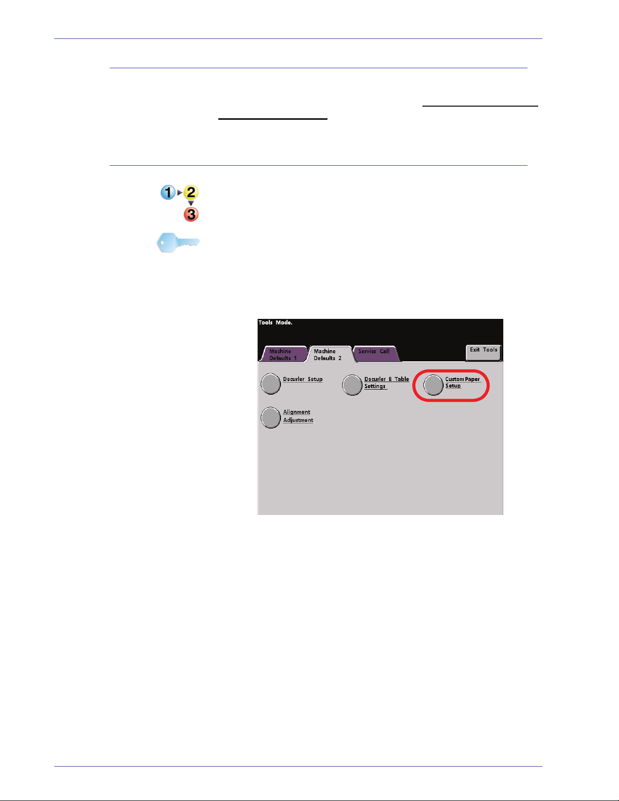
1. Access Tools Mode and touch the Alignment Adjustment
button on the Machine Defaul ts 2 screen; the following window
opens.
1-48
DocuColor 7000AP/8000AP System Administration Guide
1. Tools Mode
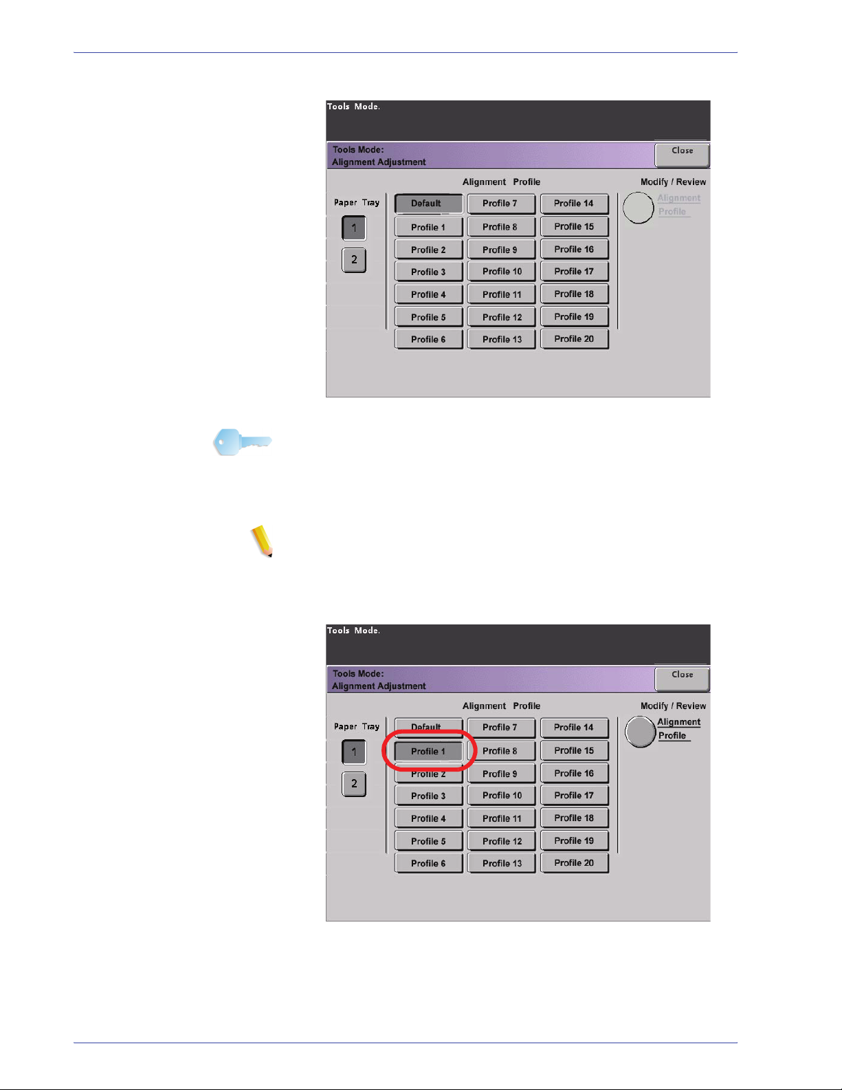
2. Select a Paper Tray.
KEY POINT: If you are creating an Alignment Profile in affiliation
with a Custom Paper Profile and have arrived here from the
Custom Paper Setup procedure, then this screen will not reflect
any Paper Tray information. The Paper Tray information was
selected earlier in your associated Custom Paper Profile.
NOTE: If you have an optional SFM attached to your digital press ,
this screen will reflect the addi tional Paper Trays 3 and 4.
3. Select a Profile number from 1-20 by touching the desired
button.
The Modify/Review button is now selectable, as shown
above.
DocuColor 7000AP/8000AP System Administration Guide
1-49

1. Tools Mode
4. Touch the Alignment Profile buttons; the Alignment Profile
window opens.
5. Touch the Test Print button; a new window opens.
a. Touch the 2 Sided button.
NOTE:If you want to check the registrati on for 1 Sided
prints only, touch the 1 Sided button.
1-50
b. Select 10 test prints by touching the Up arrow button to
change the number of test prints generated.
c. Touch the Pattern Generator button.
d. Retrieve your output test prints from the digital press.
e. Discard the first few prints, as inconsistency tends to be
greater with these images.
DocuColor 7000AP/8000AP System Administration Guide

1. Tools Mode
6. Evaluate the test prints by holding your 2 Sided output at eye
level near a light source. This will allow you to see the
registration marks for both Side 1 and Side 2 of the output.
a. If you determine that the registration between Side 1 and
Side 2 is significant and needs adjusting, proceed to the
Step 7.
b. If the registration between Side 1 and Side 2 is okay, stop
now:
– Touch the Close button to return to the Alignment
Profile window.
– Ensure that the Default button is selected and touch
the Close button.
– Exit Tools Mode.
7. Select the desired Alignment feature that you want to adjust.
Each of the above Alignment features is discussed on the
following pages.
DocuColor 7000AP/8000AP System Administration Guide
1-51

1. Tools Mode
• Lead Registration: Use this feature to adjust the lead
edge of the image for Side 1 and/or Side 2 registration.
– The factory default setting is zero (0).
– The arrows on the right side of the illustration show the
paper feed direction.
– The + sign, the left-pointing arrow, and the red lines
shows the direction the image will move on the paper
when the value is increased.
– If you select a negative value (for example, -1.0 mm),
the image on the paper moves toward the right.
• Side Registration: Use this feature to adjust the side
edge of the image for Side 1 and/or Side 2 registration.
1-52
– The factory default setting is zero (0).
DocuColor 7000AP/8000AP System Administration Guide
1. Tools Mode
– The + sign, the up arrow, and the red lines shows the
direction the image will move on the paper when the
value is increased.
– If you select a negative value (for example, -1.0 mm),
the image on the paper moves downward.
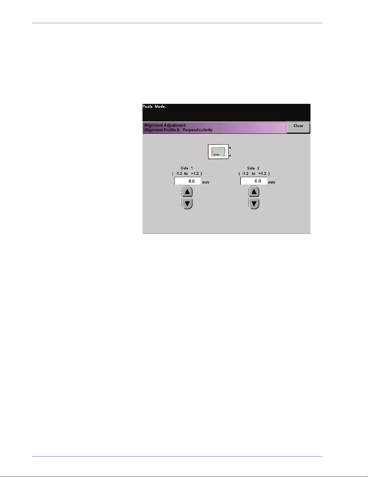
• Perpendicularity: Use this feature to adjust the image
digitally on the drum so that it will align with the paper for
both Side 1 and Side 2.
– The factory default setting is zero (0).
– The arrows on the right side of the illustration show the
paper feed direction.
– The + sign, the left-pointing arrow, and the red lines
shows the direction the image will move on the paper
when the value is increased.
– If you select a negative value (for example, -1.0 mm),
the image on the paper moves toward the right.
DocuColor 7000AP/8000AP System Administration Guide
1-53

1. Tools Mode
• Side Skew: Use this feature to adjust the paper so that
the image for Side 1 and/or Side 2 are not skewed but
aligned with each other.
– The factory default setting is zero (0).
– The arrows on the right side of the illustration show the
paper feed direction.
– The + sign, the right-curved arrow, and the red lines
shows the direction the image will move on the paper
when the value is increased.
– If you select a negative value (for example, -1.0 mm),
the image on the paper moves toward the left.
1-54
DocuColor 7000AP/8000AP System Administration Guide

1. Tools Mode
• FS Direction Image Magnification: Use this feature to
correct for image stretch from Side 1 to Side 2. The image
may be enlarged or reduced as necessary.
– FS stands for Fast Scan and it enlarges or reduces the
image in the direction shown in the illustration above.
– The factory default setting is zero (0).
– The arrows on the right side of the illustration show the
paper feed direction.
– The + sign, the up arrow, and the red line shows the
direction the image will move on the paper when the
value is increased.
– If you select a negative value (for example, -1.0 mm),
the image on the paper moves down.
DocuColor 7000AP/8000AP System Administration Guide
1-55

1. Tools Mode
• SS Direction Image Magnification: Use this feature to
correct for image stretch from Side 1 to Side 2. The image
may be enlarged or reduced as necessary.
– SS stands for Slow Scan and it enlarges or reduces the
image in the direction shown in the illustration above.
– The factory default setting is zero (0).
– The arrows on the right side of the illustration show the
paper feed direction.
– The + sign, the left-pointing arrow, and the single, black
line shows the direction the image will move on the
paper when the value is increased.
– If you select a negative value (for example, -1.0 mm),
the image on the paper moves toward the right.
1-56
DocuColor 7000AP/8000AP System Administration Guide

1. Tools Mode
8. Make the desired adjustments for one the Alignment Profile
features (Lead Registration, Side Registration, etc.).
NOTE: It is recommended that you choose only one
Alignment Profile feature unti l you run another set of Test
Prints and evaluate the reg istr ation on th at output. If you want
multiple Alignment Profile f eatures selected, individuall y select
each feature, run Test Prints for t hat feature, and evaluate the
output. After you determine that th e output for the selected
feature is acceptable, then you can select another Alignment
Profile feature to adjust.
Touch the Close button on the appropriate screen to save the
settings and return to the Alignment Profile window.
9. Select Test Print to ensure that the output is satisfactory.
a. Touch the 2 Sided button.
NOTE:If you want to check the registrati on for 1 Sided
prints only, touch the 1 Sided button.
b. Select 10 test prints by touching the Up arrow button to
change the number of test prints generated.
c. Touch the Pattern Generator button.
d. Retrieve your output test prints from the digital press.
e. Discard the first few prints, as inconsistency tends to be
greater with these images.
DocuColor 7000AP/8000AP System Administration Guide
1-57

1. Tools Mode
10. Evaluate the test prints by holding your 2 Sided output at eye
level near a light source. This will allow you to see the
registration marks for both Side 1 and Side 2 of the output.
a. If you determine that the registration between Side 1 and
Side 2 is significant and needs adjusting, repeat Steps 7-9
until you achieve satisfactory output. Proceed to the Step
11.
b. If the registration between Side 1 and Side 2 is okay, stop
now and proceed to the next step.
11. Once your output is satisfactory, select Close to save these
settings and return to the Alignment Adjustment window.
12. Select Close to save all the settings for this Alignment Profile
and return to the Machine Defaults 2 screen.
13. Close out of Tools Mode.
KEY POINT: The Alignment Profile you just created/modified is
now in affect for the specific Paper Tray that you selected in the
procedure. This Alignment Profile remains in affect until you
reenter Tools Mode and deactivate it. To deactivate an Alignment
Profile, continue to the next page.
1-58
DocuColor 7000AP/8000AP System Administration Guide

1. Tools Mode
Deactivating an Alignm ent Adjustment Profile
To switch off or deactivate an Alignment Profile, perform the
following steps:
1. Reenter Tools Mode.
2. Select Alignment Adjustment from the Machine Default 2
screen.
3. Refer to your Alignment Adjustment Profile Chart where you
recorded the selections made for the profile you want to switch
off/deactivate.
4. Select the Paper Tray for the profile you want to switch off/
deactivate.
The Profile number button selected for this Alignment Profile
will be selected. For example, the above illustration shows
that Tray 1 is assigned Alignment Profile 1.
5. Touch the Default button. This switches off the Alignment
Adjustment Profile.
• Select Close to return to the Machine Defaults 2 screen.
6. Exit the Tools Mode by touching the Close button.
DocuColor 7000AP/8000AP System Administration Guide
1-59

1. Tools Mode
Finishing System Module Profile (DFA device)
If your digital press has a third-party, Digital Finishing Architecture
(DFA) device, connected, enabled, and powered on, the option
entitled “Finishing System Module Profile” is displayed on the
Machine Defaults 2 tab.
Touch the Finishing System Module Profile button to display the
Profile List.
To view the settings for a Timing Tab or a Finishing System Profile,
touch that button. The settings for a DFA device can only be
viewed on the digital press Touch Screen. The settings are
enabled on the color server connected to your digital press.
1-60
DocuColor 7000AP/8000AP System Administration Guide
Overview
2. Auditron
KEY POINT: Some features or options described in this chapter
may not display or be selectable depending on the configuration of
your machine.
The Auditron Mode enables you to:
• Change the Tools Mode password
• Establish a separate password for access to the Auditron
Mode
• View the number of prints sent through the color server.
Use the following procedure to access the Auditron Administration
screens.
1. Press the Access button on the Control Panel.
2. Use the Control Panel keypad to enter the Tools Mode five-
digit password, and then touch the Enter button on the Touch
Screen.
3. Touch the Audit ron Administration Pathway button on the
screen. The Auditron Administration screen appears.
DocuColor 7000AP/8000AP System Administration Guide
2-1

2. Auditron
Initialization
User Accounts are individual accounts that can be set up with print
limits, color limits, a password, and copy volume limits. The
Initialization screen allows you to reset information in User
Accounts.
The Initialization screen allows you to:
• Select a total number of User Accounts; the maximum is 300,
• Change the number of User Accounts, or
• Reset all the User Account information and passwords.
2-2
DocuColor 7000AP/8000AP System Administration Guide

2. Auditron
Whenever you perform one of the above options, a confirmation
screen asks if you are sure you want to initialize the Auditron:
Responding with a “Yes” deletes all the established accounts, and
returns the Tools Mode password to the factory default of five ones
(11111).
Whether you initially setting up the Auditron, changing the total
number of user accounts, or resetting the Auditron, a message
appears at the top of the screen when you touch the Close button.
This message informs you that you must Initialize the Auditron
after performing one of the aforementioned functions. Touch the
Initialize Au d itron button and select “Yes” to complete the task.
DocuColor 7000AP/8000AP System Administration Guide
2-3

2. Auditron
Create/Modify User Accounts
The Create/Modify User Accounts screen enables you to create
user accounts, passwords, or review existing account privileges.
You are also able to change the default password for entering the
Tools Pathway and to create a new password for the Auditron
Mode, if so desired.
Account 1 is reserved for the System Administrator by factory
default. This account is set up with access to both Tools and
Auditron. Th e d efault p a s swor d i s set t o 11111 and can be
changed by the System Administrator.
2-4
DocuColor 7000AP/8000AP System Administration Guide

Creating a User Account
Use the following procedure to create a User Account.
NOTE: To undo the last change that you made, touch the Undo
button at the top of the screen. The last setting that you changed
is returned to its previous value.
1. Touch the Create/Modify User Accounts button on the Auditron
Administration screen. The Create/Modify User Accounts
screen appears.
2. Auditron
2. Select the next open account by doing one of the following:
a. Touch the From Keypad button.
– Use the Control Panel keypad to enter the account
number for this User Account.
– Touch the Enter button on the bottom left side of the
screen to save your entry; or
b. Simply touch the Next Open Account button.
DocuColor 7000AP/8000AP System Administration Guide
2-5
2. Auditron
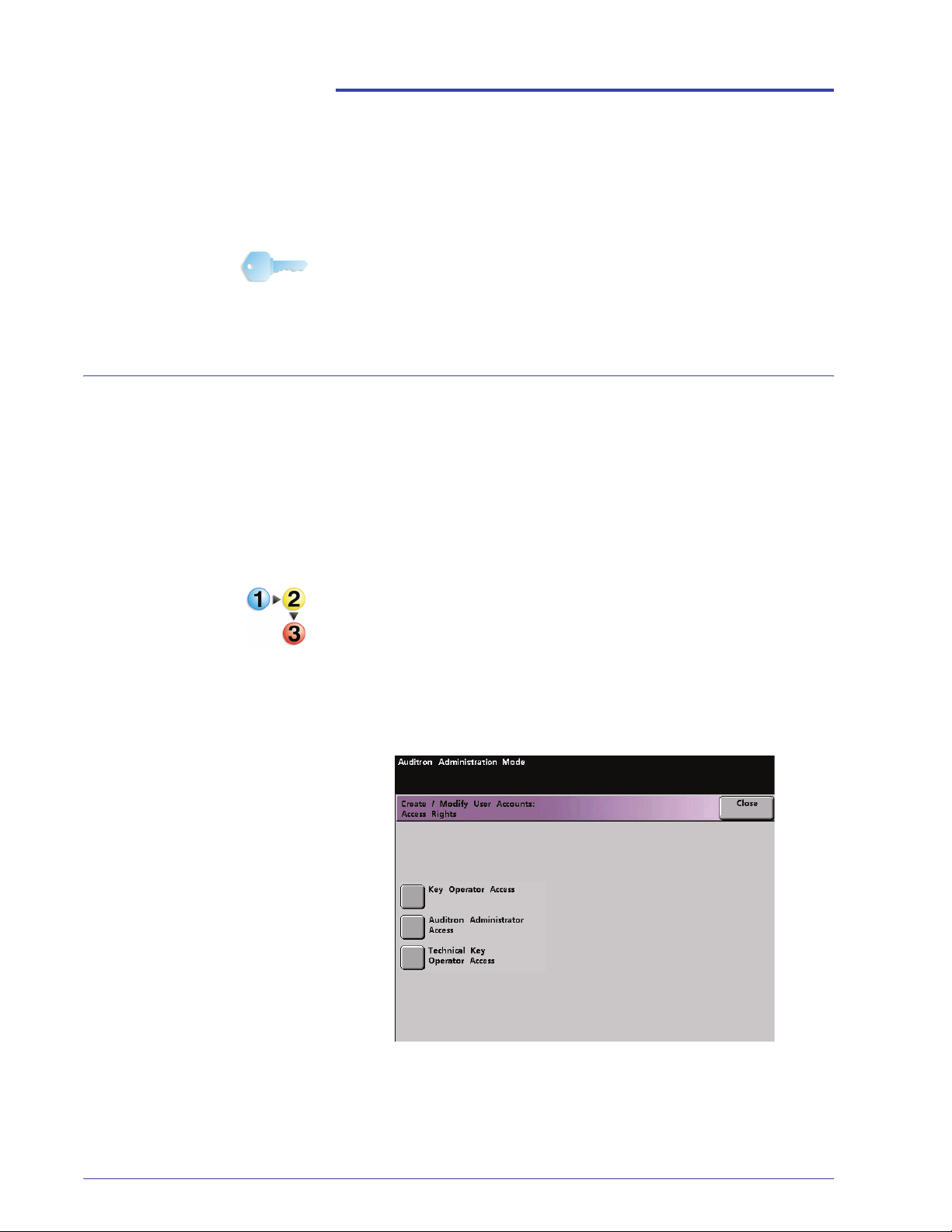
3. Set the level of access for the individual using the account by
touching the Access Rights button.
4. Touch one of the following buttons:
– Key Operator Access
– Auditron Administrator
– Technical Key Operator Access
NOTE:The optional Technical Key Operator feature may
or may not be activated with your configuration.
2-6
DocuColor 7000AP/8000AP System Administration Guide
2. Auditron
5. Touch the Close button to return to the Create/Modify User
Accounts screen.
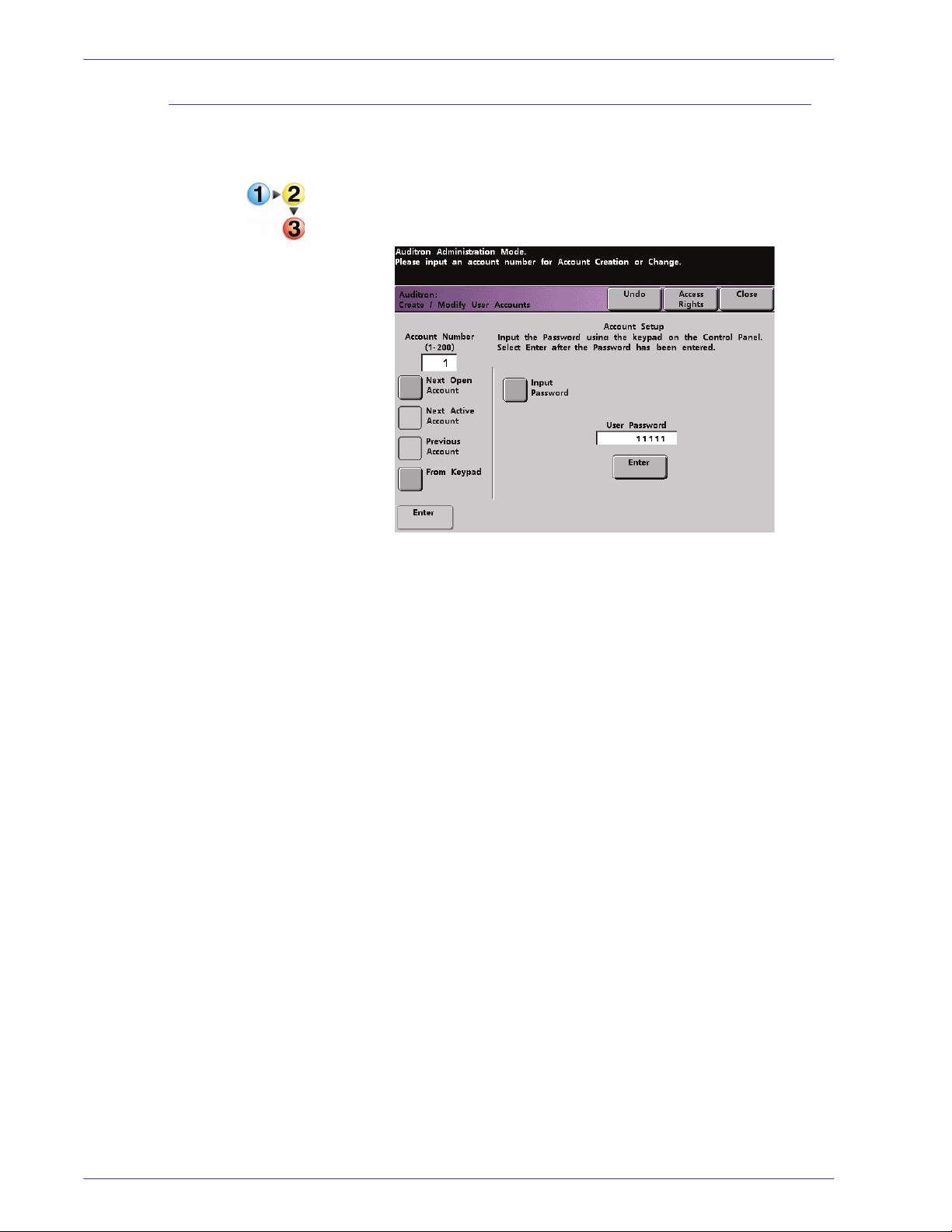
6. Touch the Input Password button.
a. Use the Control Panel keypad to enter the unique five-digit
password for this account.
b. Touch the Enter button in the center of the screen. The
password you enter is displayed in the User Password
field.
7. Touch the Enter button in the center of the screen to enter your
settings into the system.
8. Touch the Close button to return to the Auditron Administration
screen.
9. Exit the Auditron Mode to activate the new settings for this
User Account.
DocuColor 7000AP/8000AP System Administration Guide
2-7

2. Auditron
Modifying a User Account
Use the following procedure to modify a User Account.
NOTE: To undo the last change that you made, touch the Undo
button at the top of the screen. The last setting that you changed
will be returned to its previous value.
1. Touch the Create/Modify User Accounts button on the Auditron
Administration screen. The Create/Modify User Accounts
screen appears.
2. Review Steps 2-9 in Creating a User Account on for
information on how to change specific settings on this screen.
3. Touch the Next Open Account or Previous Account button to
modify the settings for additional User Accounts. Touch the
Next Active Account button to modify the settings for the next
active User Account.
4. Touch the Close button to return to the Auditron Administration
screen.
5. Exit the Auditron Mode to activate the new settings for this
User Account.
2-8
DocuColor 7000AP/8000AP System Administration Guide
Changing the Tools Mode Password
Use the following procedure to change the Access password for
the Tools Mode.
1. Touch the Create/Modify User Accounts button on the Auditron
Administration screen. The Create/Modify User Accounts
screen appears.
2. Auditron
Account 1 is displayed on the next screen with the default
password of five 1s (11111).
2. Touch the Input Password button. Use the Control Panel
keypad to enter a new password. The new password is
displayed in the User Password field.
3. Touch Enter on the Touch Screen. The new password takes
effect the next time you access the Tools Mode.
DocuColor 7000AP/8000AP System Administration Guide
2-9

2. Auditron
Creating a Password for the Auditron Mode
Use the following procedure to create a unique password for
accessing the Auditron Mode.
1. Touch the Create/Modify User Accounts button on the Auditron
Administration screen. The Create/Modify User Accounts
screen appears.
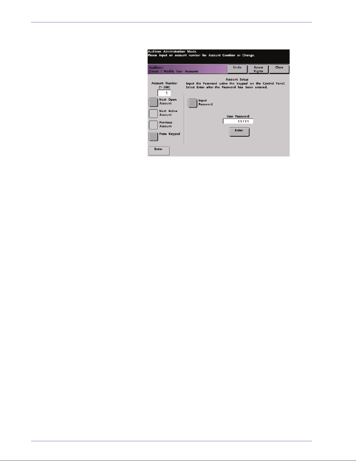
2. Touch the Next Open Account button. The number 2 is
displayed in the Account Number field.
You can use any open account number for the Auditron
Pathway password by touching the Next Active Account
button.
3. Touch the Input Password button. Use the Control Panel
keypad to enter the unique five-digit password for this account.
The password you enter is displayed in the User Password
field.
4. Touch the Enter button to save your entry.
2-10
DocuColor 7000AP/8000AP System Administration Guide

2. Auditron
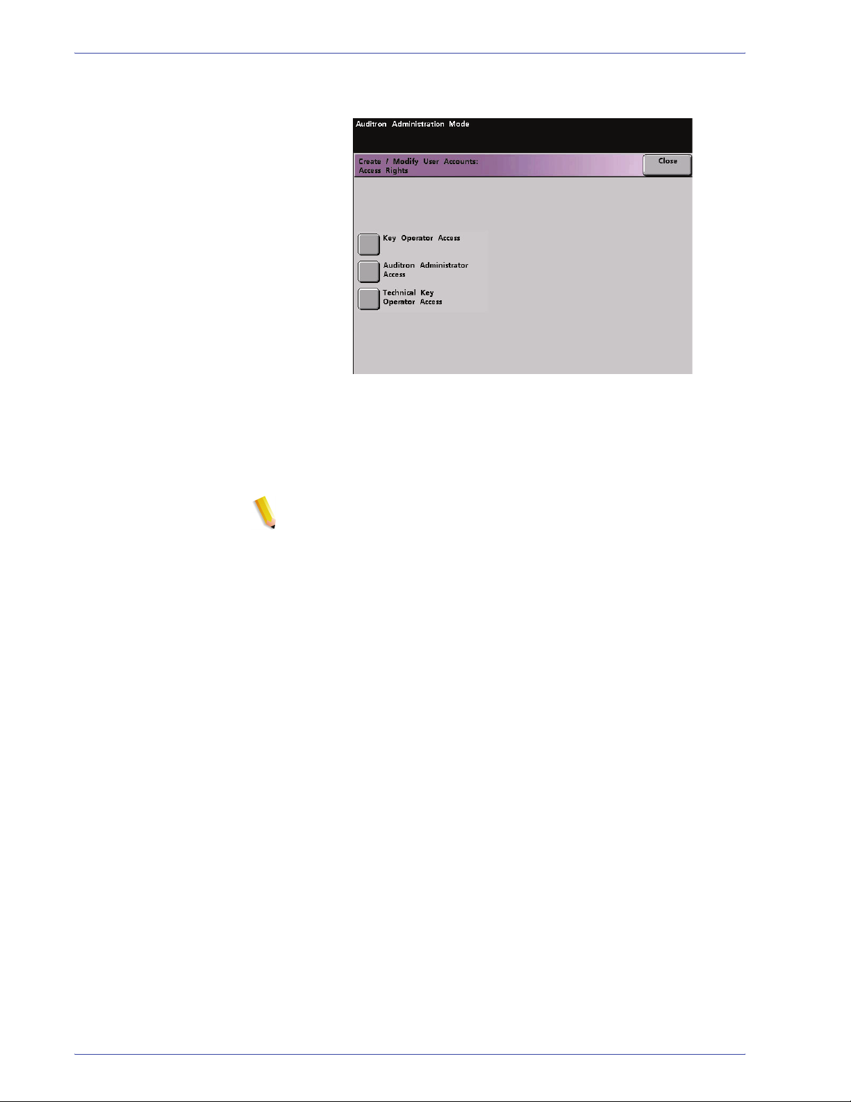
5. Touch the Access Rights button at the top of the screen. The
Access Rights screen appears.
6. Touch the Audit ron Administrator Access button.
7. Touch the Close button.
8. Touch the Enter button on the Create/Modify User Accounts
screen.
9. Touch the Close button on the Create/Modify User Accounts
screen.
10. Exit the Auditron Mode to activate the new password.
DocuColor 7000AP/8000AP System Administration Guide
2-11

2. Auditron
Review Printer Job Account
Use the Review Printer Job Account screen to determine the
number of print jobs sent from the color server connected to your
digital press.
The meters show volumes for the following copy types:
Depending on your digital press configuration, you may or may not
have an additional printing volume meter on this screen.
To reset these meters to zero, touch the Reset button. A
confirmation screen asks if you are sure you want to reset the
meters.
NOTE: Resetting these meters does not reset the meters shown
on the Meters screen that is accessed through the Machine
Details screen on the Touch Screen.
2-12
DocuColor 7000AP/8000AP System Administration Guide

Charts
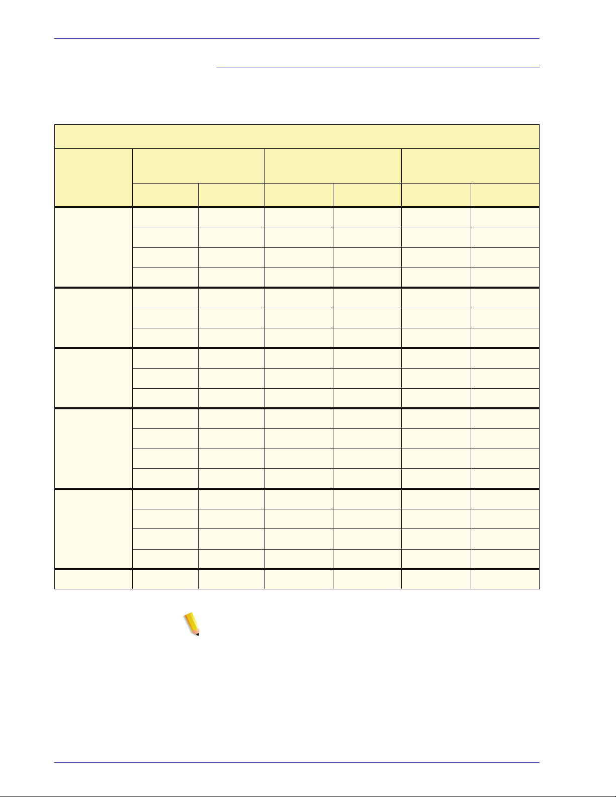
E Table Settings Chart: Type E1
E Table Settings
Paper Type E Table Decurler Type
Single
Paper
Weight
Type E1
Type E2
Simplex:
Straight
(10 mm)
Lower
Lower
(6 mm)
Lower
(2 mm)
Upper
(10 mm)
Upper
(6 mm)
Simplex: In
Mixed
Paper
Weight
Type E3
Type E4
Reverse
________ mm
Duplex:
Side 1 to
Side 2
________ mm _________ mm ________ mm _______ mm _______ mm
Duplex:
Type E5
Type E6
1. Record the original, manufacturer default settings by placing a check mark in the appropriate boxes that apply for the original E Type settings, including Paper Type, E Table, and Decurler Type.
Side 2 to
Side 1
Duplex
Decurler
Upper
(2 mm)
2. Touch the E Table Settings button (from the Decurler E Table Settings window) and then enter the number for each E Type Table Setting in the E
Table Settings columns above.
Charts-1

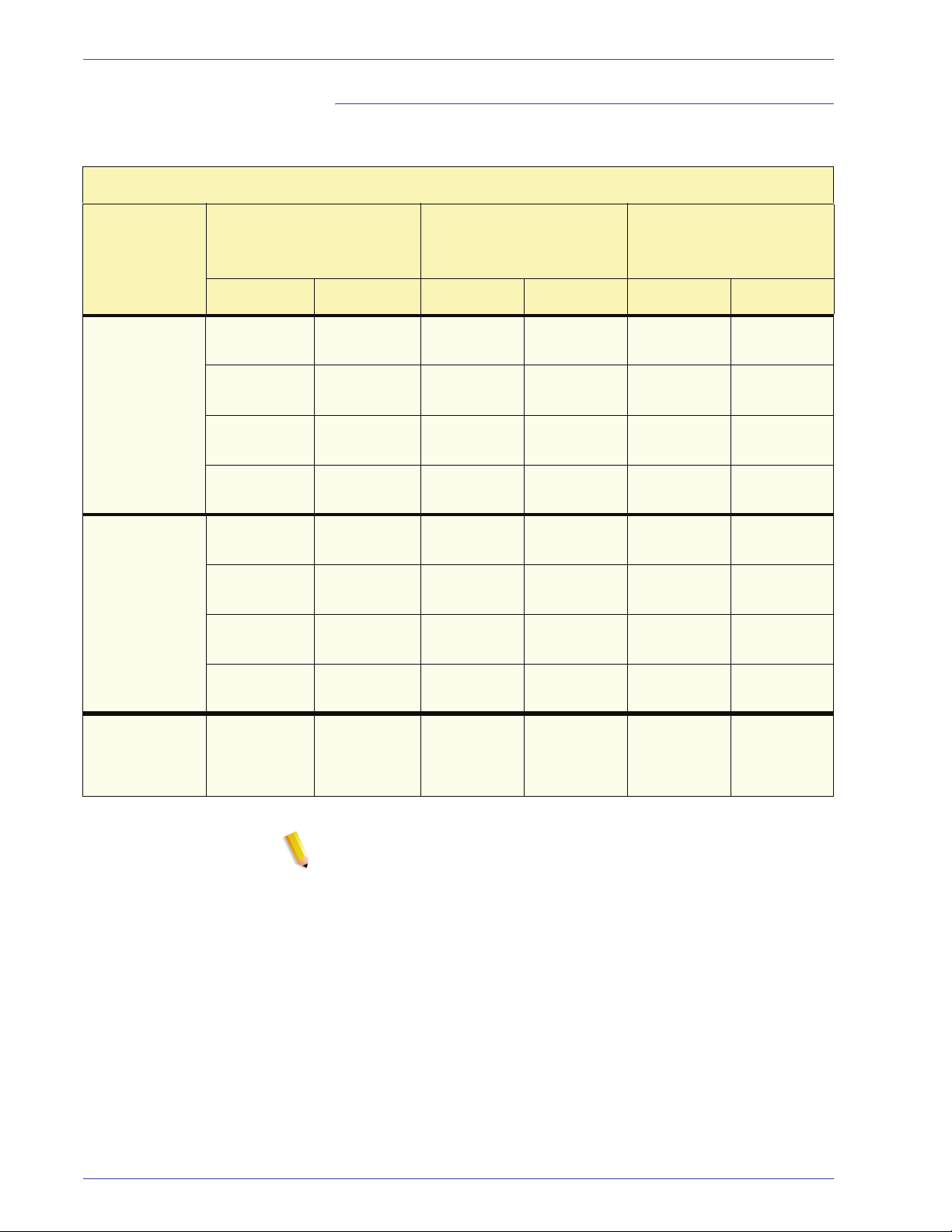
E Table Settings Chart: Type E2
E Table Settings
Paper Type E Table Decurler Type
Single
Paper
Weight
Type E1
Type E2
Simplex:
Straight
Lower
(10 mm)
Lower
(6 mm)
Lower
(2 mm)
Upper
(10 mm)
Upper
(6 mm)
Simplex: In
Mixed
Paper
Weight
Reverse
Type E3
Duplex: Side
1 to Side 2
Type E4
________ mm ________ mm _________ mm ________ mm _______ mm _______ mm
Duplex: Side
2 to Side 1
Type E5
Duplex
Decurler
Type E6
1. Record the original, manufacturer default settings by placing a check mark in the appropriate boxes that apply for the original E Type settings, including Paper Type, E Table, and Decurler Type.
Upper
(2 mm)
2. Touch the E Table Settings button (from the Decurler E Table Settings window) and then enter the number for each E Type Table Setting in the E
Table Settings columns above.
Charts-2

E Table Settings Chart: Type E3
E Table Settings
Paper Type E Table Decurler Type
Single
Paper
Weight
Type E1
Type E2
Simplex:
Straight
Lower
(10 mm)
Lower
(6 mm)
Lower
(2 mm)
Upper
(10 mm)
Upper
(6 mm)
Simplex: In
Mixed
Paper
Weight
Type E3
Type E4
Reverse
Duplex:
Side 1 to Side
2
________ mm ________ mm _________ mm ________ mm _______ mm _______ mm
Duplex:
Type E5
Type E6
1. Record the original, manufacturer default settings by placing a check mark in the appropriate boxes that apply for the original E Type settings, including Paper Type, E Table, and Decurler Type.
Side 2 to Side
1
Duplex
Decurler
Upper
(2 mm)
2. Touch the E Table Settings button (from the Decurler E Table Settings window) and then enter the number for each E Type Table Setting in the E
Table Settings columns above.
Charts-3

E Table Settings Chart: Type E4
E Table Settings
Paper Type E Table Decurler Type
Single
Paper
Weight
Type E1
Type E2
Simplex:
Straight
Lower
(10 mm)
Lower
(6 mm)
Lower
(2 mm)
Upper
(10 mm)
Upper
(6 mm)
Simplex: In
Mixed
Paper
Weight
Type E3
Type E4
Reverse
Duplex: Side
1 to
Side 2
________ mm ________ mm _________ mm ________ mm _______ mm _______ mm
Duplex: Side
Type E5
Type E6
1. Record the original, manufacturer default settings by placing a check mark in the appropriate boxes that apply for the original E Type settings, including Paper Type, E Table, and Decurler Type.
2 to
Side 1
Duplex
Decurler
Upper
(2 mm)
2. Touch the E Table Settings button (from the Decurler E Table Settings window) and then enter the number for each E Type Table Setting in the E
Table Settings columns above.
Charts-4

E Table Settings Chart: Type E5
E Table Settings
Paper Type E Table Decurler Type
Single
Paper
Weight
Type E1
Type E2
Simplex:
Straight
Lower
(10 mm)
Lower
(6 mm)
Lower
(2 mm)
Upper
(10 mm)
Upper
(6 mm)
Simplex: In
Mixed
Paper
Weight
Type E3
Type E4
Reverse
Duplex:
Side 1 to Side
2
________ mm ________ mm _________ mm ________ mm _______ mm _______ mm
Duplex:
Type E5
Type E6
1. Record the original, manufacturer default settings by placing a check mark in the appropriate boxes that apply for the original E Type settings, including Paper Type, E Table, and Decurler Type.
Side 2 to Side
1
Duplex
Decurler
Upper
(2 mm)
2. Touch the E Table Settings button (from the Decurler E Table Settings window) and then enter the number for each E Type Table Setting in the E
Table Settings columns above.
Charts-5
E Table Settings Chart: Type E6
E Table Settings
Paper Type E Table Decurler Type
Single
Paper
Weight
Type E1
Type E2
Simplex:
Straight
Lower
(10 mm)
Lower
(6 mm)
Lower
(2 mm)
Upper
(10 mm)
Upper
(6 mm)
Simplex: In
Mixed
Paper
Weight
Type E3
Type E4
Reverse
Duplex:
Side
1 to Side 2
________ mm ________ mm _________ mm ________ mm _______ mm _______ mm
Duplex:
Type E5
Type E6
1. Record the original, manufacturer default settings by placing a check mark in the appropriate boxes that apply for the original E Type settings, including Paper Type, E Table, and Decurler Type.
Side
2 to Side 1
Duplex
Decurler
Upper
(2 mm)
2. Touch the E Table Settings button (from the Decurler E Table Settings window) and then enter the number for each E Type Table Setting in the E
Table Settings columns above.
Charts-6

Custom Paper Setup Chart
Custom Profile 1
Paper
Tray #
1
2
3
4
Paper Type Switch
Off
60-80 g/m
81-105 g/m
2
Uncoated
2
106-135 g/m
136-186 g/m
187-220 g/m
221-300 g/m
Transparency
60-80 g/m
81-105 g/m
2
Coated
2
106-135 g/m
136-186 g/m
187-220 g/m
221-300 g/m
Uncoated
2
Uncoated
2
Uncoated
2
Uncoated
2
Uncoated
Coated
2
Coated
2
Coated
2
Coated
2
Coated
Custom Paper Adjustment
Base Range of Paper Type 2nd BTB
60-80 g/m
81-105 g/m
106-135 g/m
136-186 g/m
187-220 g/m
221-300 g/m
60-80 g/m
81-105 g/m
106-135 g/m
136-186 g/m
187-220 g/m
221-300 g/m
2
Uncoated
2
Uncoated
2
Uncoated
2
Uncoated
2
Uncoated
2
Uncoated
2
Coated
2
Coated
2
Coated
2
Coated
2
Coated
2
Coated
Side 1:
(50-150%)
____________%
Side 2:
(50-150%)
____________%
Decurler
Penetration
Amount
Auto
Type A
Type B
Type C
Type D
Type E1
Type E2
Type E3
Type E4
Type E5
Type E6
Aligner NIP
Pressure
(-30 to
+30)
___________
Pulse
Air Assist
Operation
Selection
Auto
Do Not
Operate
Operate
Alignment
Adjustment
Refer to
Alignment Profile
Number:
Default
1 2
3 4
5 6
7 8
9 10
11 12
13 14
15 16
17 18
19 20
When making selections for your Custom Paper Profile, place a check mark in the appropriate boxes that apply for the settings you select, and where
applicable, enter the number you choose for that setting.
Charts-7
Custom Paper Setup Chart
Custom Profile 2
Paper
Tray #
1
2
3
4
Paper Type Switch
Off
60-80 g/m
81-105 g/m
2
Uncoated
2
106-135 g/m
136-186 g/m
187-220 g/m
221-300 g/m
Transparency
60-80 g/m
81-105 g/m
2
Coated
2
106-135 g/m
136-186 g/m
187-220 g/m
221-300 g/m
Uncoated
2
Uncoated
2
Uncoated
2
Uncoated
2
Uncoated
Coated
2
Coated
2
Coated
2
Coated
2
Coated
Custom Paper Adjustment
Base Range of Paper Type 2nd BTB
60-80 g/m
81-105 g/m
106-135 g/m
136-186 g/m
187-220 g/m
221-300 g/m
60-80 g/m
81-105 g/m
106-135 g/m
136-186 g/m
187-220 g/m
221-300 g/m
2
Uncoated
2
Uncoated
2
Uncoated
2
Uncoated
2
Uncoated
2
Uncoated
2
Coated
2
Coated
2
Coated
2
Coated
2
Coated
2
Coated
Side 1:
(50-150%)
____________%
Side 2:
(50-150%)
____________%
Decurler
Penetration
Amount
Auto
Type A
Type B
Type C
Type D
Type E1
Type E2
Type E3
Type E4
Type E5
Type E6
Aligner NIP
Pressure
(-30 to
+30)
___________
Pulse
Air Assist
Operation
Selection
Auto
Do Not
Operate
Operate
Alignment
Adjustment
Refer to
Alignment Profile
Number:
Default
1 2
3 4
5 6
7 8
9 10
11 12
13 14
15 16
17 18
19 20
When making selections for your Custom Paper Profile, place a check mark in the appropriate boxes that apply for the settings you select, and where
applicable, enter the number you choose for that setting.
Charts-8

Custom Paper Setup Chart
Custom Profile _______
Paper
Tray #
1
2
3
4
Paper Type Switch
Off
60-80 g/m
81-105 g/m
2
Uncoated
2
106-135 g/m
136-186 g/m
187-220 g/m
221-300 g/m
Transparency
60-80 g/m
81-105 g/m
2
Coated
2
106-135 g/m
136-186 g/m
187-220 g/m
221-300 g/m
Uncoated
2
Uncoated
2
Uncoated
2
Uncoated
2
Uncoated
Coated
2
Coated
2
Coated
2
Coated
2
Coated
Custom Paper Adjustment
Base Range of Paper Type 2nd BTB
60-80 g/m
81-105 g/m
106-135 g/m
136-186 g/m
187-220 g/m
221-300 g/m
60-80 g/m
81-105 g/m
106-135 g/m
136-186 g/m
187-220 g/m
221-300 g/m
2
Uncoated
2
Uncoated
2
Uncoated
2
Uncoated
2
Uncoated
2
Uncoated
2
Coated
2
Coated
2
Coated
2
Coated
2
Coated
2
Coated
Side 1:
(50-150%)
____________%
Side 2:
(50-150%)
____________%
Decurler
Penetration
Amount
Auto
Type A
Type B
Type C
Type D
Type E1
Type E2
Type E3
Type E4
Type E5
Type E6
Aligner NIP
Pressure
(-30 to
+30)
___________
Pulse
Air Assist
Operation
Selection
Auto
Do Not
Operate
Operate
Alignment
Adjustment
Refer to
Alignment Profile
Number:
Default
1 2
3 4
5 6
7 8
9 10
11 12
13 14
15 16
17 18
19 20
When making selections for your Custom Paper Profile, enter the Customer Profile number. Place a check mark in the appropriate boxes that apply for
the settings you select, and where applicable, enter the number you choose for those settings.
Charts-9

Custom Paper Setup Chart
Custom Profile _______
Paper
Tray #
1
2
3
4
Paper Type Switch
Off
60-80 g/m
81-105 g/m
2
Uncoated
2
106-135 g/m
136-186 g/m
187-220 g/m
221-300 g/m
Transparency
60-80 g/m
81-105 g/m
2
Coated
2
106-135 g/m
136-186 g/m
187-220 g/m
221-300 g/m
Uncoated
2
Uncoated
2
Uncoated
2
Uncoated
2
Uncoated
Coated
2
Coated
2
Coated
2
Coated
2
Coated
Custom Paper Adjustment
Base Range of Paper Type 2nd BTB
60-80 g/m
81-105 g/m
106-135 g/m
136-186 g/m
187-220 g/m
221-300 g/m
60-80 g/m
81-105 g/m
106-135 g/m
136-186 g/m
187-220 g/m
221-300 g/m
2
Uncoated
2
Uncoated
2
Uncoated
2
Uncoated
2
Uncoated
2
Uncoated
2
Coated
2
Coated
2
Coated
2
Coated
2
Coated
2
Coated
Side 1:
(50-150%)
____________%
Side 2:
(50-150%)
____________%
Decurler
Penetration
Amount
Auto
Type A
Type B
Type C
Type D
Type E1
Type E2
Type E3
Type E4
Type E5
Type E6
Aligner NIP
Pressure
(-30 to
+30)
___________
Pulse
Air Assist
Operation
Selection
Auto
Do Not
Operate
Operate
Alignment
Adjustment
Refer to
Alignment Profile
Number:
Default
1 2
3 4
5 v 6
7 8
9 10
11 12
13 14
15 16
17 18
19 20
When making selections for your Custom Paper Profile, enter the Customer Profile number. Place a check mark in the appropriate boxes that apply for
the settings you select, and where applicable, enter the number you choose for those settings.
Charts-10
Alignment Adjustment Profile Chart
Alignment Profile 1
Lead
Registration
Side 1:
(-2.0 to +2.0)
____________mm
Side 2:
(-2.0 to +2.0)
____________mm
When making selections for your Alignment Adjustment Profile, place a check mark in the appropriate boxes that apply for the settings you select, and
where applicable, enter the number you choose for the selected settings.
Side Registration Perpendicularity Side Skew
Side 1:
(-2.0 to +2.0)
____________mm
Side 2:
(-2.0 to +2.0)
____________mm
Side 1:
(-1.2 to +1.2)
____________mm
Side 2:
(-1.2 to +1.2)
____________mm
Side 1:
(-2.0 to +2.0)
____________mm
Side 2:
(-2.0 to +2.0)
____________mm
FS Direction
Image Magnification
Side 1:
(-0.400 to +0.400)
____________%
Side 2:
(-0.400 to +0.400)
____________%
SS Direction
Image Magnification
Side 1:
(-0.400 to +0.400)
____________%
Side 2:
(-0.400 to +0.400)
____________%
Charts-11
Alignment Adjustment Profile Chart
Alignment Profile 2
Lead
Registration
Side 1:
(-2.0 to +2.0)
____________mm
Side 2:
(-2.0 to +2.0)
____________mm
When making selections for your Alignment Adjustment Profile, place a check mark in the appropriate boxes that apply for the settings you select, and
where applicable, enter the number you choose for the selected settings.
Side Registration Perpendicularity Side Skew
Side 1:
(-2.0 to +2.0)
____________mm
Side 2:
(-2.0 to +2.0)
____________mm
Side 1:
(-1.2 to +1.2)
____________mm
Side 2:
(-1.2 to +1.2)
____________mm
Side 1:
(-2.0 to +2.0)
____________mm
Side 2:
(-2.0 to +2.0)
____________mm
FS Direction
Image Magnification
Side 1:
(-0.400 to +0.400)
____________%
Side 2:
(-0.400 to +0.400)
____________%
SS Direction
Image Magnification
Side 1:
(-0.400 to +0.400)
____________%
Side 2:
(-0.400 to +0.400)
____________%
Charts-12

Alignment Adjustment Profile Chart
Alignment Profile______ _
Lead
Registration
Side 1:
(-2.0 to +2.0)
____________mm
Side 2:
(-2.0 to +2.0)
____________mm
When making selections for your Alignment Adjustment Profile, enter the Alignment Profile Number. Place a check mark in the appropriate boxes that
apply for the settings you select, and where applicable, enter the number you choose for the selected settings.
Side Registration
Side 1:
(-2.0 to +2.0)
____________mm
Side 2:
(-2.0 to +2.0)
____________mm
Perpendicularity Side Skew
Side 1:
(-1.2 to +1.2)
____________mm
Side 2:
(-1.2 to +1.2)
____________mm
Side 1:
(-2.0 to +2.0)
____________mm
Side 2:
(-2.0 to +2.0)
____________mm
FS Direction
Image Magnification
Side 1:
(-0.400 to +0.400)
____________%
Side 2:
(-0.400 to +0.400)
____________%
SS Direction
Image Magnification
Side 1:
(-0.400 to +0.400)
____________%
Side 2:
(-0.400 to +0.400)
____________%
Charts-13

Alignment Adjustment Profile Chart
Alignment Profile______ _
Lead
Registration
Side 1:
(-2.0 to +2.0)
____________mm
Side 2:
(-2.0 to +2.0)
____________mm
When making selections for your Alignment Adjustment Profile, enter the Alignment Profile Number. Place a check mark in the appropriate boxes that
apply for the settings you select, and where applicable, enter the number you choose for the selected settings.
Side Registration Perpendicularity Side Skew
Side 1:
(-2.0 to +2.0)
____________mm
Side 2:
(-2.0 to +2.0)
____________mm
Side 1:
(-1.2 to +1.2)
____________mm
Side 2:
(-1.2 to +1.2)
____________mm
Side 1:
(-2.0 to +2.0)
____________mm
Side 2:
(-2.0 to +2.0)
____________mm
FS Direction
Image Magnification
Side 1:
(-0.400 to +0.400)
____________%
Side 2:
(-0.400 to +0.400)
____________%
SS Direction
Image Magnification
Side 1:
(-0.400 to +0.400)
____________%
Side 2:
(-0.400 to +0.400)
____________%
Charts-14


 Loading...