

Page 1
THE DOCUMENT COMPANY
XEROX
Phaser 790/DocuColor 2006
Service Manual
March 2001
701P35949
CAUTION
Certain components in the Phaser 790/DocuColor
2006 are susceptible to damage from electrostatic
discharge. Observe all ESD procedures to avoid
component damage.
Page 2

Prepared by:
Xerox Corporation
Global Knowledge & Language Services
800 Phillips Road Bldg. 845-17S
Webster, New York 14580-9791
USA
© 2000 by Xerox Corporation. All rights reserved. Copyright protection
claimed includes all forms and matters of copyrightable material and information now allowed by statutory or judicial law or hereinafter granted,
including without limitation, material generated from the software programs
that are displayed on the screen such as styles, templates, icons, screen
displays, looks, etc.
***XEROX DocuLock Pr otect Until Forever ***
XEROX®, The Document Company®, the stylized X and the identifying
product names and numbers herein are trademarks of XEROX CORPORATION. Other company trademarks are also acknowledged.
NOTICE
While every care has been taken in the preparation of this manual, no liability will be accepted by Xerox Corporation arising out of any inaccuracies or
omissions.
NOTICE
All service documentation is s upplied t o X erox external customers for informational purposes only. Xerox service documentation is intended for use by
certified product trained service personal only. Xerox does no t warrant or
represent that such documentation i s complete, nor does Xerox represent
or warrant that it will notify or provide to such customer any future changes
to this documentation. Custo mer performed service of equipment, or modules, components or parts of such equipment may affect the warranty
offered by Xerox with respect to such equipment. You should consult the
applicable warranty for its terms regarding customer or third party provided
service. If the customer services such equipment, modules, components or
parts thereof, the customer releases Xerox from any and all liability for the
customer actions, and the customer agree s to indemnify, defend and hold
Xerox harmless from any third party claims which arise directly or indirectly
from such se r vice.
WARNING
This equipment generates, uses an d can radia te radio frequ ency
energy, and if not installed and used in accordance with the instructions documentation, may cau se interferen ce to radio commu ni cations. It has been tested and found to comply with the limits for a
Class A computing device pursuant to subpart J of part 15 of FCC
rules, which are designed to provide reas onabl e prote ction agains t
such interference when operated in a comme rci al environm en t. Operation of this equipment in a residential area is likely to cause interference in which case the user, at his own expense, will be required to
correct the interference.
WARNING
This machine contains an invisible laser. There is no visual indication
that the laser beam is present. During servicing, the machine is a
Class 3B product because of the invisible laser. the laser beam could
cause eye damage if looked at directly. Service procedures must be
followed exactly as written without change. The service representative
must observe the established local laser safety precaution s when servicing the machine. Do not place tools with a reflective surface into
the ROS opening. Do not look in the area of the ROS window if the
power is On and the laser is energized.
Page 3

About this Manual ........................................................................................................... iii
Organization....................................................................................................................iii
How to Use this Docum en ta tio n. ............... .... .... ............... .... .... ............... .... .... ............... . iii
Symbology ...................................................................................................................... iii
Introduction
Initial Issue
Phaser 790/DocuColor 2006
10/00
i
Introduction
Page 4

Introduction
10/00
ii
Initial Issue
Phaser 790/DocuColor 2006
Page 5

About this Manual
This Service Manual is part of the multinational documentation system for the Phaser 790
Printe r and D C 20 06 Copie r./Prin ter The Se rv ice Do cum ent atio n is u sed in or der t o d iagn ose
machine malfunctions, adjust components and has information which is used to maintain the
product in superior operating condition. It is the controlling publication for a service call. Information on its use is found in the Introduction of the Service Documentation.
Adjustments
Adjustments include procedures for adjusting the parts that must be within specification for the
correct operation of the system.
Use the adjustment procedures for the correct sequence of operation for specifications, warnings, ca utions and notes.
This ma nual contains information that applies to NASG and ESG copiers.
Service Manual Revision
The Service Manual will be updated as the machine changes or as problem areas are identified.
Organization
This Service Manual is divided i nto nine sections. The titles of t he sections a nd a description of
the information contained in each section are contained in the following paragraphs:
Section 1 Service Call Procedures
This se ct ion contai ns pr o c ed ur e s t ha t de te r mi ne w ha t ac ti on s are to be t ak e n d ur i ng a service
call on the machine and in what sequence they are to be completed. This is the entry level for
all service calls.
Section 2 Status Indicator RAPs
This s ection co ntains the diagnostic aids for troublesho oting th e Fault Co de and no n-Fault
Code rel ate d faults (with the exceptio n of co py qua lity problem s ) .
Section 3 Image Quality
This sect io n con tai ns t he diagno st i c aid s for trou bl es ho otin g an y cop y qu alit y pr obl ems , as well
as copy quality specifications and copy defect samples.
Section 4 Repairs/Adjustments
This section contains all the Adjustments and Repair procedures.
Repairs
Repair s include p rocedures f or remov al and replac ement of pa rts which have the fol lowing
special co nditions :
When removal or repla c ement cann ot be determined from the expl oded view of the
Parts List.
When there is a cleaning or a lubricating activity associated with the procedure.
When the part requires an adjustment after replacement.
When a special tool is required for removal or replacement.
Use the repair proc edures for the correct order of r emoval and replacement, fo r warnings, cautions, an d no tes .
Section 5: Parts Lists
This section con tains the Prin ter/Copier Parts List.
Section 6: General Procedures/Inform ation
This section contains General Procedures, Diagnostic Programs, and Copier Information.
Section 7: Wiring Data
This sec tion contains drawings, lists of plug/jack locations, and diagrams of the power distribution w i re networ ks i n the mac hi ne . I nd ividual w i re networks a r e s h ow n in the Circ ui t D i ag r am s
contained in Section 2. This section also contains the Block Schematic Diagrams.
How to Use this Documentation
The Service Call Procedures in Section 1 describe the sequence of activities used during the
service call. The call must be entered using these procedures.
Use of the Circuit Diagrams
Circuit Diagrams (CDs) are included in Sections 2 (Status Indicator RAPs) and 3 (Image Quality RAPs) of the Service Manual. All wirenets, with the exception of power distribution wirenets,
are shown on the CDs. Po wer distribution wirenets are show n in Section 7 (W iring D ata) of the
Service Manual. The power distribution wirenets on the CDs will end at the terminal board for
the power being distributed. Find the wirenet for that power and locate the terminal board on
the wirenet. Use the wirenet to troubleshoot any power distribution wiring not shown on the
CD.
Use of the Block Schematic Diagrams
Block Schematic Diagrams (BSDs) are included in Section 7 (Wiring Data) of the Service Manual. The BSDs show the functional relationship of the electrical circuitry to any mechanical, or
non-m echa nic al, input s or outpu ts t hroug hout the mach ine. Inpu ts an d out puts suc h as mo to r
drive, mechanical li nkages, operator actions, a nd air flow are shown. The BSDs will provide an
overa ll view of how the entire sub s ys te m, such as ADF, works.
It should be not ed th at the BS Ds no lon ger co nt ain an Inp ut Power Bloc k re f err ing to Chai n 1. It
will be necessary to refer to the Wirenets in order to trace a wire back to its source.
Symbology
The following reference symbols are used throughout the documentation.
Initial Issue
Phaser 790/DocuColor 2006
10/00
iii
Introduction
Page 6

Warnin gs, Ca utions, and Notes
Warnings, Cautions, and Notes will be found throughout the Service Documentation. The
words WARNING or CAUTION may be liste d on an illustra tion when the specif ic comp onent
associated with the potential hazard is pointed out; however, the message of the WARNING or
CAUTION is always located in the text. Their definitions are as follows:
WARNING
A Warning is us ed whenev er an op e rat ing or main t en an ce procedu r e, a p rac t ic e, condition, or statement, if not strictly observed, could result in personal injury.
CAUTION
A Cautio n is us ed whe ne ver an o perat ing or main te nanc e proc edur e, a p ractic e , cond ition , or
statement, if not strictly observed, could result in damage to the equipment.
NOTE: A Note i s us ed when ev er i t i s n ec e ss ary to hig h l igh t a n op erating or mainten an ce procedure, practice, condition, or statement.
Flags
The Flag symbol indicates a reference point into a Circuit Diagram from a RAP. Instructions will
be given to check for an open circuit, a short circuit, or an intermittent condition.
Note
This sy mbol refers to notes which are found on the same page as the Circuit Diagram.
Parts List
In this symbol, exampl e (PL2.1), refers to the Parts List on which the part can be found.
Machine Safety Icons
The following sa fety icons are displayed on the machine:
WARNING
The Phaser 790/Dc 2006 contains an invisible laser. There is no visual indication that the
laser b eam is pr esent . Du rin g ser vicin g, the mach ine is a Class 3 B pr odu ct bec au se of
the in vi sible laser. th e l as er be am could ca us e ey e d am ag e i f lo ok ed at d i rec t ly. Serv ice
proced ure s must be fol low ed ex ac tly as w ri tte n wi tho ut cha nge. The se r vic e r epr es ent ative m ust observe the establis hed local laser safety precaution s when serv icing the
machi ne. Do not pl ac e t oo ls with a reflective surface in th e ar e a of the Char ge Co r otr o n
or the RO S op eni ng. Do not lo ok in the a rea o f the RO S wind ow if the powe r is O n and
the las er i s en er gized.
The following symbol and statement appear on a label in the machine. The symbol by
itself , or the sym bol and the st atemen t may also appear in the servi ce docu menta tion
and in the training program. When this symbol appears, the service representative is
warned that conditions exist that could result in exposure to the laser beam.
WARNING
Do not t ry to byp ass an y la ser interl ocks for an y rea son. P erma ne nt eye d ama ge coul d
result if the laser is accidentally directed into your eye.
Figure 1 Laser Hazard Symbol
Adjustments
The adjustment symbol refers to an procedure in the Adjust ment section of t his Manu al.
Test Points, Test Stakes, Test Holes
This symbol is used to indicate that a test point, test stake, or test hole is available for accessing a sign al line . The pref ix befo re th e iden tific at ion num ber in di cate s whe ther the acc ess is a
test point (TP), a test stake (TS), or a test hole (TH).
Bracket
The bracket symbol indicates a C omponent Control Code se lection in a Diagnostic Program.
Introduction
Laser Hazard Statement
DANGER INVISIBLE LASER RADIATION WHEN OPEN. AVOID DIRECT EXPOSURE TO
BEAM.
CAUTION
The use of controls or adjustments other than those specified in the Laser Safety Training Program may result in an exposure to da ngerous laser radiation.
For additional information, review the Laser Safety Training pr ogram.
An arrow points to the location to install, to gain access to, or to release an object.
This symbol indicates that a surface can be hot. Use caution when reaching in the machine to
avoid t ouching the hot surfaces.
10/00
iv
Phaser 790/DocuColor 2006
Initial Issue
Page 7
Danger l ab e l in di cates wh er e electrical curr e nt s exist when the m a chine is cl os ed and op er a ting. Use caution when reaching in the machine.
These symbols indicate components that may be damaged by Electrostatic Discharge (ESD).
Electrostatic Discharge (ESD) Field Service Kit
The purpose of the ESD Protection Program is to preserve the inherent r eliability and qu ality of
electro ni c c om po nents that ar e ha nd le d by the Field S erv ic e Pe rs on ne l. Th is pr o gra m is be ing
implem e nte d now as a di r ec t r e su lt of adva nc e s i n m ic ro ci r c uit r y tec h nology, as well as a new
acknowledgment of the magnitude of the ESD problem in the electronics industry today.
This program will reduce Field Service costs that are charged to PWB failures. Ninety percent
of all PWB fa il u res th at are E SD rel at e d do no t occu r immedi at el y. Using th e ESD Fi el d Ser vi ce
Kit will eliminate these delayed failures and intermittent problems caused by ESD. This will
improv e product rel ia bi lity and red uc e ca ll ba cks.
The ESD Field Service Kit should be used whenever Printed Wiring Boards or ESD sensitive
components are being handled. This includes activities like replacing or reseating of circuit
boards or connectors. The kit s hould also be used in order to prevent additional damage when
circuit boards are returned for repair.
The instr uctions for us ing the ESD Fi eld Service Ki t can be found in ES D Field Service Kit
Usage in the Gen eral Pr ocedures secti on of the Service Documentati on.
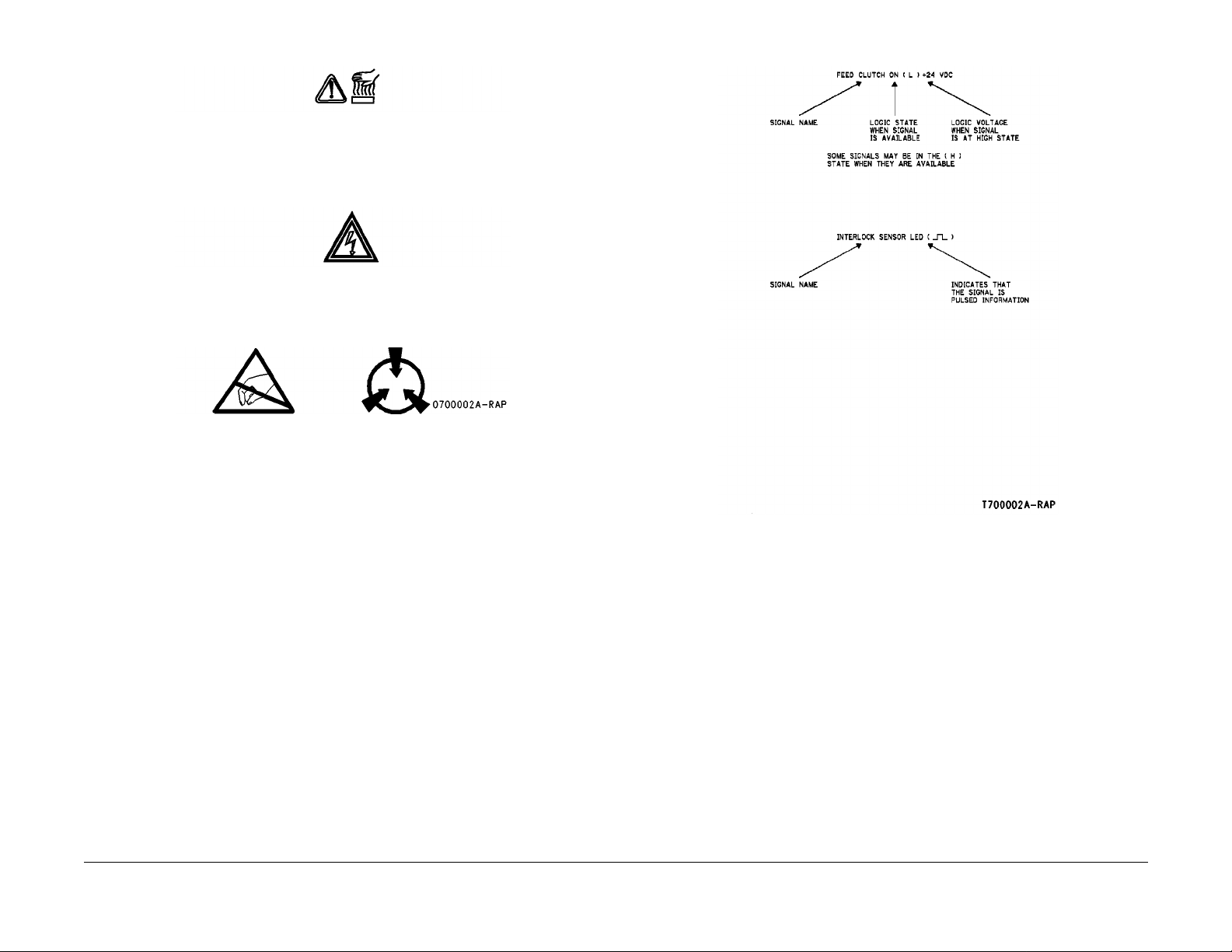
Signal Nomenclature
Refer to Figure 2 for an example of Signal Nomenclature.
Initial Issue
Phaser 790/DocuColor 2006
10/00
v
Figure 2 Signal Nomenclature
Introduction
Page 8

Voltage Measurement and Specification s
Measurements of DC voltage must be made with reference to the specified DC Common,
unless some other poin t is refer enced i n a diagnostic procedure. All me asurements of AC volt-
age should be made with respect to the adjacent return or ACN wire.
T able 1 Vol tage Measurement and Specifications
VOLTAGE SPECIFICATION
INPUT POWER 220 V 198 VAC T O 242 VAC
INPUT POWER 100 V 90 VAC T O 135 VAC
INPUT POWER 120 V 90 VAC TO 135 VAC
+5 VDC +4.75 VDC TO +5.25 VD C
+24 VDC +23.3 7 VDC TO +27.06 VD C
Logic Voltage Levels
Measurements of logic levels must be made with reference to the specified DC Common,
unless some other point is referenced in a diagnostic procedure.
Table 2 Logic Levels
VOLTAGE H/L SPECIFICATIONS
+5 VDC H= +3.00 TO +5.25 VD C
L= 0.0 TO 0.8 VDC
+24 VDC H= +23.37 TO +27.06 VDC
L= 0.0 TO 0.8 VDC
DC Voltage Measurements in RAPs
The RAPs have been designed so that when it is required to use the DMM to measure a DC
voltage, the first test point listed is the location for the red (+) meter lead and the second test
point is the location for the black meter lead. For example, the following statement may be
found i n a RAP:
There is +5 VDC from TP7 to TP68.
In this example, the red meter lead would be placed on TP7 and the black meter lead on TP68.
Another example of a statement found in a R AP might b e:
There is -15 VDC from TP21 to TP33.
In thi s ex am p l e , t he red me ter lead w o ul d be place d on T P 21 a nd the bl ac k m eter lead w ou ld
be placed on TP33.
If a seco nd tes t poi nt is no t given , it is ass ume d th at the bl ack m ete r lead m ay be at tac hed to
the copier frame.
Introduction
10/00
vi
Initial Issue
Phaser 790/DocuColor 2006
Page 9

Service Call Procedures.................................................................................................. 1-3
Initial Actions Procedure ................................................................................................. 1-3
Call Flow Procedure........................................................................................................ 1-4
Cleaning Procedures....................................................................................................... 1-5
Final Actions.................................................................................................................... 1-5
1 Service Call Procedures
Initial Issue
Phaser 790/DocuColor 2006
10/00
1-1
Service Call Proce dure s
Page 10

Service Call Proce dure s
10/00
1-2
Initial Issue
Phaser 790/DocuColor 2006
Page 11

Service Call Procedur es
Service Strategy
The service strategy for the Phaser 790 Printer and the DC 2006 Copier/Printer is to run to failure. The Repair Analysis Procedures (RAPs) will be used to diagnose and repair any problems.
Problem s that oc cur in the B asic Print er mode wi ll be repa ired befo re problem s that occ ur
when using the accessories.
Image quality problems should be repaired after all other problems are repaired.
Service Call Procedures
The Service Call Procedures are a guide for performing any service on the Phaser 790
Printer and the DC 2006 Copier/Printer. The procedures are designed to be used with the
Phaser 79 0 Printer and th e DC 2006 Copier/ Printer Service Manual. Perform each step in
order.
Initial Actions
The Ini tial Actions gath er informa t io n ab ou t th e condition o f th e ma c hine and the problem t h at
caused the service call.
Call Flow
Call Flow summarizes the sequence of the Service Call Procedures .
Cleaning Proc ed ures
The clea nin g pr o c ed ur e s lis t w ha t nee ds t o be cl ea ne d at ea ch serv ic e call.
Final Actions
The Final Action s will test the copier /printer and return it to th e customer. Ad ministrative activities are also perform ed in the Final Actions.
Initial Actions Procedure
Purpose
The p urpose of the Initia l Acti ons se ction of the Servic e Cal l Proc edures is to d eterm ine the
reason for the se rvice call and to identif y and organize the actions which m ust be performed.
Procedure
1. Gather the information about the service call and the condition of the copie r/prin ter.
a. Question the operator(s). Ask about the location of the most recent paper jams. Ask
about th e image qu al ity and the ge neral performanc e of the c op ie r /p r in te r, inc lu di ng
any unusual sounds or other indications (if applicable).
b. Check that the power cords are in good condition, correctly plugged into the power
source, and free from any defects that would be a safety hazard. Repair or replace
the power cords as required. Check that the circu it breakers are not tripped.
c. Ensure that all paper trays are loaded with paper.
d. Inspect an y rejected c op ie s. I n qu ire as to, o r ot he r wis e determi ne, the pap er quality
and weight. The specified paper for optimum image quality for the Phaser 790
Printer is Hammermill Laser Print 24. The specified paper for optimum image quality
for t he DC 20 06 Co pier/P rinter is 24# X erox COLOR Xpre ssions o r Col otech + 90
gms. Look for any damage to the copies, oil marks, image quality defects, or other
indica tions of a problem.
e. Record the billing meter r eadings .
f. Check the Service Log for any recent activities that are related to the problem that
caused the service call or any secondary problem.
2. Check the Image Quality by performing the V isual Calibration (GP 16 ).
a. Run four copies of the 82E13030 Test Pattern.
b. Check the image quality. If the customer has identified any Image Quality Defects or
problem s, go to the IQ1 Imag e Q uality Entry RAP.
3. If there is a problem in the Basic Printer Mode, go to the Call Flow Procedure.
4. If there are no problems in the Basic Printer Mode, go to the Final Actions.
Initial Issue
Phaser 790/DocuColor 2006
10/00
1-3
Service Call Proce dure s
Service Call Procedures, Initial Actions Procedure
Page 12

Call Flow Procedure
This procedure should be performed at every serv ice cal l.
Procedure
The copier/printer is capable of making a copy/print to the Output Tray.
YN
The copier/printer is capable of making a copy/print to the Top Tray.
YN
The problem is in the paper path.
YN
A Fault Code or a message is constantly displayed.
YN
The Display is blank or garbled.
YN
If one or mo re of the butto ns or LEDs doe s not functi on, go to the
002-702 IOT Control Panel Button/LED RAP.
Go to the 002-701 Blank/Gar bled IO T Display RAP.
F
Go to the area w here the no ise is bein g gene rat ed and troubl esh oo t
that area.
If a sorter fault code is present, go to the RAP associated with that fault
code.
If a sorter message is present, go to the Section 2, Fault Message/RAP
Cross-Reference Table.
Check for mechanical binding.
Check the AD F Documen t Sensor s for debris or damage.
Check that the document mechanical drives and feed rolls are free from wear, damage, con tamination, and binding.
Check the pape r path se nsors for debri s or dama ge. Chec k that pa per is l oaded in all
trays correctly.
Check the paper path mechanical drives and rolls for contamination, glazing, wear, damage, or binding.
Go to the IQ1 Image Quality Entry RAP.
If a fault code is dis p laye d, g o to the Fault C o de RAP for th e Fa ul t Cod e th at is
displayed.
If a message is displayed, go to the Fault Message/RAP Cross-Reference in
Section 2.
Check t he pape r pat h s enso rs fo r de br is or dama ge. Chec k th at pape r is l oa ded i n
all trays correctly.
Check t h e pa pe r p ath m ec hanical dri ves and rol ls f o r contamin a tion, glaz in g, wear, damage, or binding.
The copier is capable of making a copy/print to the Top Tray.
YN
Check t h e pa pe r p ath m ec hanical dri ves and rol ls f o r contamin a tion, glaz in g, wear, damage, or binding.
A Fault Code or message is constantly d isplayed.
YN
The problem is Image Quality.
YN
The problem is in the ADF.
YN
The problem is in the Scanner.
YN
The problem is in the Sorter.
YN
The problem is noise.
YN
The problem is inte r m itt ent. Go to th e BS D an d perform a resistance c he c k o f t h e wires in qu es t io n . G en t ly pu ll on t he wir e s to
ensure that they are properly connected.
If a fault code is displayed, go to the Fault Code RAP for the Fault Code that is displayed.
If a message is displayed, go to the F ault Message/RAP Cross-Reference in Section 2.
AABBCCDDEEF
Service Call Proce dure s
Call Flow Procedure
10/00
1-4
Initial Issue
Phaser 790/DocuColor 2006
Page 13

Cleaning Procedures
Purpose
The purpose is to provide cleaning procedures to be per formed at every call.
Final Actions
Purpose
The intent of this procedure is to be used as a guide to follow at the end of every service call.
Procedure
CAUTION
Do not use any solvents unless directed to do so by the Service Manual.
Gene ral Cleaning
Use a dry lint free cloth or a lint free cloth moistened with water for all cleaning unless directed
otherwise by the Service Manual. Wipe with a dry lint free cloth if a moistened cloth is used.
1. Feed Components (Rolls and Pads)
Follow the General Cl eaning procedure above.
2. Dry Ink Dispense Uni ts
Vacuum the Dry Ink Dispense units.
3. Jam Sensors
Clean the sensor s with a dry cotton swab.
4. IBT Cle ani ng
Check the IBT Belt surface and wipe with a dry lint free clot h. If the surface is exce ssively
dirty, replace the IBT Belt (PL 7.2).
5. Fus e r Compon en t s (best cleaned w hen hot).
Wipe with a lint free c loth.
6. Scanner
a. Switc h off the power and allow the Exposure Lamp to cool off.
b. Using the optical Cleaning Cloth, clean the front and rear of the Document Glass,
Document Cover, White Reference Strip, Reflector, and Mirror.
c. Clean the Exposure Lamp with a clean cloth and Film Remover.
7. ADF
Check the paper path for debris or damage. Clean the rolls with a clean cloth and Film
Remover as required.
8. Sorter
Check the paper path for debris or damage. Clean the Sorter with a dry lint free cloth.
Procedure
1. Ensure that the exterior of the copier/printer and the adjacent area are clean. Use a dry
cloth or a cloth moistened with water to clean the copier/printer. Do not use solvents.
2. Check the supply of consumables. Ensure that an adequate supply of consumables is
avail ab le acc ording to loca l op er a tin g pr o c ed ur e s.
3. Conduct any operator training that is needed. Ensure that the operator understands that
the Visu alCal proced ure in the Ope rator Manual should be used to adju st the colors .
Ensure that the operator can perform the VisualCal procedure (reference the GP 16
Visual Calibration procedure).
4. Complete the Se rvice Log.
5. Perform the following steps to make a copy of the Demonstration Original for the Customer:
a. Load Paper in Tray 1 with 8-1/2 x 11 inch (A4) or 11 x 17 inch, 24# Xerox COLOR
Xpressions or Colotech + 90 gms for the DC 2006 Copier/Printer, or Hammermill
Laser Print 24 for the Phaser 790
b. Place Test Pattern 82E13030 on the glass with the short edge of the test pattern reg-
istered to the left edg e of the glass. Sel ect Tray 1 and make a single copy.
c. Print a Configuration Page (GP 14).
d. Print a test page (for the printer only).
e. Present the copies to the customer.
6. Issue copy credits as neede d.
7. Discuss the service call with the customer to ensure that the customer understands what
has been done and is satisfied with t he results of the service call.
Initial Issue
Phaser 790/DocuColor 2006
10/00
1-5
Service Call Proce dure s
Cleaning Procedures, Final Actions
Page 14

Service Call Proce dure s
Cleaning Procedures, Final Actions
10/00
1-6
Initial Issue
Phaser 790/DocuColor 2006
Page 15

2 Status Indicator RAPs
Fault Message Cross-ref erence
Fault Message/RAP Cross-Reference............................................................................ 2-3
Standby Power
001-701 AC Power RAP ................................................................................................. 2-5
001-702 +5 VDC Power RAP.......................................................................................... 2-7
001-703 +24 VDC Interlocked Power RAP..................................................................... 2-9
001-704 Front Cover Open RAP..................................................................................... 2-11
001-705 ROS +5 VDC Switched Voltage RAP ............................................................... 2-13
001-706 Area 1 Open RAP ............................................................................................. 2-15
001-707 Area 2 Open RAP ............................................................................................. 2-17
001-708 Area 3 Open RAP ............................................................................................. 2-19
001-709 Area 4 Open RAP ............................................................................................. 2-21
001-710 Area 5 Open RAP ............................................................................................. 2-23
001-711 Area 6 Open RAP ............................................................................................. 2-25
001-712 IIT DC Power RAP............................................................................................ 2-27
User Interface
002-310, 906, 907, 908 IIT Control Panel Failure RAP.................................................. 2-29
002-701 Blank/Garbled IOT Display RAP ....................................................................... 2-29
002-702 IOT Control Panel Button/LED RAP ................................................................. 2-31
Machine Run Control
003-310 Feeder Communications Failure RAP .............................................................. 2-33
003-311 Duplex Communications Failure RAP............................................................... 2-35
003-312 Sorter Communications Failure RAP................................................................ 2-37
003-333 Foreign Interface RAP ...................................................................................... 2-39
003-334 Foreign Interface Compatibility RAP................................................................. 2-41
003-356 IOT NVM RAM Error RAP................................................................................. 2-43
003-400 IOT Firmware Error RAP................................................................................... 2-45
003-701 Copy/Print Cartridge Error RAP........................................................................ 2-45
Start Print Power
004-320 Paper Handling Motor RAP............................................................................... 2-47
004-322 Fuser Motor RAP.............................................................................................. 2-49
Document Transportat ion
005-210 Nudger Home RAP ........................................................................................... 2-51
005-211 ADF Power RAP ............................................................................................... 2-53
005-220/221 ADF Communications RAP........................................................................ 2-55
005-700 ADF Fault Entry RAP........................................................................................ 2-57
005-701 ADF Entrance Jam RAP ................................................................................... 2-58
005-702 ADF Exit Jam RAP............................................................................................ 2-60
005-703 ADF No Feed RAP............................................................................................ 2-62
005-704 Unfinished Copy Job RAP ................................................................................ 2-64
Imaging
006-310 IIT Registration RAP ......................................................................................... 2-67
006-311 Exposure Lamp RAP ........................................................................................ 2-69
006-312 FPC CCD RAP.................................................................................................. 2-70
006-313 IIT Cooling Fans RAP ....................................................................................... 2-71
006-372 Start of Scan Error RAP.................................................................................... 2-73
006-701 Angle Sensor RAP............................................................................................ 2-75
006-702 Platen Switch RAP............................................................................................ 2-77
006-703 Scanner Error RAP ........................................................................................... 2-79
006-704 System Error (093-XXX) RAP........................................................................... 2-79
006-906/907/908/909 RAP.............................................................................................. 2-80
Paper Supply
007-324 Environment Sensor RAP ................................................................................. 2-81
007-340 Feeder Motor Fail RAP ..................................................................................... 2-83
007-341 Inverter Motor Fail RAP..................................................................................... 2-85
007-700 Tray 1 Open RAP.............................................................................................. 2-87
007-701 Tray 2 Open RAP.............................................................................................. 2-89
007-702 Tray 3 Open RAP.............................................................................................. 2-91
007-703 Tray 1 Empty RAP ............................................................................................ 2-93
007-704 Tray 2 Empty RAP ............................................................................................ 2-95
007-705 Tray 3 Empty RAP ............................................................................................ 2-97
007-706 Bypass Tray Empty RAP................................................................................... 2-99
007-707 Paper Length Mismatch RAP............................................................................ 2-101
007-708 Bypass Tray Lift RAP........................................................................................ 2-102
007-709 Tray 2 Lift Up RAP ............................................................................................ 2-104
007-710 Tray 3 Lift Up RAP ............................................................................................ 2-107
007-711 Tray 1 Paper Size Not Detected RAP............................................................... 2-110
007-712 Tray 2 Paper Size Not Detected RAP............................................................... 2-112
007-713 Tray 3 Paper Size Not Detected RAP............................................................... 2-114
Paper Transportation
008-700 Area 1 Jam RAP ............................................................................................... 2-117
008-701 Area 2 Jam RAP ............................................................................................... 2-120
008-702 Area 3 Jam RAP ............................................................................................... 2-123
008-703 Area 4 Jam RAP ............................................................................................... 2-125
008-704 Area 6 Jam RAP ............................................................................................... 2-127
008-705 Top Tray Full RAP............................................................................................. 2-130
008-706 OHP Sensor RAP.............................................................................................. 2-132
008-707 Duple x Tra y Open RA P.. .... .... ............... .... .... ............... .... .... ............... .... .... ... ... 2-1 34
Xerographics
009-321 TR0 Sensor RAP............................................................................................... 2-137
009-323 Process Motor RAP........................................................................................... 2-139
009-326 Rotary Motor RAP............................................................................................. 2-141
009-340 ADC Cleaning Failure RAP............................................................................... 2-143
009-341 ADC Sensor Background RAP.......................................................................... 2-145
009-342 Patch Error RAP................................................................................................ 2-147
009-343 PCDC Error RAP............................................................................................... 2-149
009-344 Image Density Error RAP.................................................................................. 2-149
009-358 BTR 2 Home Position RAP............................................................................... 2-150
Initial Issue
Phaser 790/DocuColor 2006
10/00
2-1
Status Indicator RAPs
Page 16

009-359 BTR 2 Bias RAP ............................................................................................... 2-152
033- 320/321 Scanner ErrorCheck RAP............................................................................ 2- 214
033-910 Scanner Memory Overflow RAP......................................................................... 2- 216
033-942 SCSI Bus Reset RAP.......................................................................................... 2- 217
021-210/211 Accessories Error RAP................................................................................. 2- 212
XX82 Fault Code RAP.........................................................................................................2- 211
009-360 Developer Fan RAP.......................................................................................... 2-154
009-700 Toner Cartridge Detached RAP........................................................................ 2-156
009-701 Toner Cartridge Empty RAP............................................................................. 2-158
009-702 Waste Container Full RAP................................................................................ 2-160
009-703 Waste Container Detached RAP ...................................................................... 2-162
009-704 Belt Cleaner RAP.............................................................................................. 2-164
Fusing and Copy Transportation
010-317 Temperature Sensor Circuit Error RAP ............................................................ 2-167
010-353/3 56 /3 57 Fuse r Low/ U nd er Te mpera tu re C ondi tio n R AP .. ................ ... .... ......... 2-168
010-354 Fuser Te mp era tu re Not D et ecte d RA P.................. .... .... ... ................ ... .... ......... 2-170
010-355 Fuser Overheat Error RAP................................................................................ 2-172
010-358 Fuser Fan Error RAP ........................................................................................ 2-174
010-359 Exit Chute Fan Failure RAP.............................................................................. 2-176
010-700 Area 5 Jam RAP............................................................................................... 2-178
010-701 Faulty Temperature Sensor RAP...................................................................... 2-180
010-702 Faulty Entrance Sensor RAP............................................................................ 2-182
010-703 Faulty Fuser Exit Sensor RAP .......................................................................... 2-184
010-704 Faulty Fuser Chute Fan RAP............................................................................ 2-186
010-705 Faulty Exchange Solenoid RAP........................................................................ 2-188
Sorter
011-700 Sorter Not In Correct Position RAP................................................................... 2-191
011-701 Sorter Bin Jam RAP.......................................................................................... 2-193
011-702 Sorter Cover Open RAP ................................................................................... 2-196
011-703 Sorter Transport Jam RAP................................................................................ 2-198
011-704 Sorter Noise RAP.............................................................................................. 2-200
011-705 Full Sensor RAP ............................................................................................... 2-202
011-706 Cannot Select Sorter RAP ................................................................................ 2-204
Imaging Control
016-310 Font ROM Checksum Error RAP...................................................................... 2-207
016-312 ESS Hard Drive Error RAP ............................................................................... 2-207
016-313 ASIC Access Error RAP.................................................................................... 2-208
016-315 ESS RAM (Bank 1) RAP................................................................................... 2-208
016-316 ESS RAM (Bank 2) RAP................................................................................... 2-209
016-317 ESS ROM RAP ................................................................................................. 2-209
016-323/324/325 ESS NVM RAM Failure RAP .............................................................. 2-210
016-330/331/332/333/334/335/336 Interface Error RAP................................................. 2-210
016-370 IOT to ESS Communication Failure RAP ......................................................... 2-211
IIT Communications
033-210 Print er Dete c tio n RAP.. .... ............... .... .... ............... .... .... ............... .... ... ............. 2-21 3
033-211/212 IOT/IIT Disconnection RAP........................................................................ 2-213
033-221/222/223/224/225/226/226/227/228 IOT/IIT Communication RAP .................... 2-214
033-330/331/332 Software Error RAP ............................................................................ 2-214
033-340/341/342/343/344/345/350 ASIC Error RAP ...................................................... 2-215
033-360/3 61 /3 70/37 1 M emory Er ror RAP..... .... ............... .... .... .... ............... .... ... ............. 2-215
033-380/390 1394 Failure RAP....................................................................................... 2-216
033-921/922/930/934/935/936/937 IOT/IIT Communication RAP .................................. 2-216
033-940/9 41/9 43 /94 4/ 94 5 SCSI Erro r RAP .. .... ............... .... .... ............... .... .... ... ............. 2-21 7
Status Indicator RAPs
10/00
2-2
Initial Issue
Phaser 790/DocuColor 2006
Page 17
Fault Message/RAP Cross-Reference
For all "??82 Faults" displayed on Prnter Display, go to XX82 Fault Code RAP
NOTE:
NOTE: For all ADF Jam messages displayed on the Scanne r Display, go to the 005-700 RAP.
For all Scanner Error messages displayed on the Scanner Display, which do not have an
associ ated Fault Code RAP, go to the 006-7 03 RAP.
For all Sy st em Er ror (093-XXX) messages displayed on the Scanner Display, go to the 006-
704 RAP.
If the message on the IOT display contains a numeric fault code, go to the RAP for that code.
To find the appropriate RAP for an unclearable message that does not contain a fault code, go
to Table 1. Locate the message in column one, and go to the RAP listed in column two.
T able 1
If this message is displayed Go to this RAP
Check Loading of <tray> In Use 007-707 Paper Length Mismatch RAP
Check Sorter Position 011-700 Sorter Not In Correct Position RAP
Clear Jam In Area 1 008-700 Area 1 Jam RAP
Clear Jam In Area 2 008-701 Area 2 Jam RAP
Clear Jam In Area 3 008-702 Area 3 Jam RAP
Clear Jam In Area 4 008-703 Area 4 Jam RAP
Clear Jam In Area 5 010-700 Area 5 Jam RAP
Clear Jam In Area 6 008-704 Area 6 Jam RAP
Clear Jam In Duplex Tray 008-707 Duplex Tray Jam RAP
Close Area 1 001-706 Area 1 Open RAP
Close Area 2 001-707 Area 2 Open RAP
Close Area 3 001-708 Area 3 Open RAP
Close Area 4 001-709 Area 4 Open RAP
Close Area 5 001-710 Area 5 Open RAP
Close Area 6 001-711 Area 6 Open RAP
Close Duplex Tray 008-707 Duplex Tray Open RAP
Close Fr on t C ov er 00 1- 704 Front Cov er Op en RA P
Close Paper T ray 1 007-700 Tray 1 Open RAP
Close Paper T ray 2 007-701 Tray 2 Open RAP
Close Paper T ray 3 007-702 Tray 3 Open RAP
Close Sorter Cover 011-702 Sorter Top Cover Open RAP
Empty Sorter Bins 011-701 S orter Bin Jam RAP
Empty Stacker Tray 011-705 Full Sensor RAP
Empty Top Tray 008-705 Top Tray Full RAP
Install <col or> Ink Ca rtrid ge 009-700 Toner Cartridge Detache d RAP
Install Copy/Print Cartridge 003-701 Copy/Print Cartridge Error RAP
Install Waste Container 009-703 Waste Container Detached R AP
Jam in Sorter 011-701 Sorter B in Jam RAP
Load <s iz e> 007-711 Tray 1 Paper Siz e N ot D et ec t ed RA P
007-712 Tray 2 Paper Size Not Detected RAP
007-713 Tray 3 Paper Size Not Detected RAP
Table 1
If this message is displayed Go to this RAP
Load <s ize> In Bypass Tray 007-706 Bypass Tray Empty RAP
Load <size> In Tray 1 007-703 Tray 1 Empty RAP
Load <size> In Tray 2 007-704 Tray 2 Empty RAP
Load <size> In Tray 3 007-705 Tray 3 Empty RAP
Order Copy/Print Cartridge 003-701 Copy/Print Cartridge Error RAP
Reload <size> in Bypass Tray 007-708 Bypass Tray Lift RAP
Reload <size > in Tray 2 007-709 Tray 2 Lift Up RAP
Reload <size > In Tray 3 007-710 Tray 3 Lift Up RAP
Replace Copy/Print Cartridge 003-701 Copy/Print Cartridge Error RAP
Waste Container Full 009-702 Waste Container Full RAP
Initial Issue
Phaser 790/DocuColor 2006
10/00
2-3
Status Indicator RAPs
Fault Message/RAP Cross-Reference
Page 18

Status Indicator RAPs
Fault Message/RAP Cross-Reference
10/00
2-4
Initial Issue
Phaser 790/DocuColor 2006
Page 19

001-701 AC Power RAP
Initial Actions
• Ensure AC Power is available at the wall receptacle.
• Ensure the Power Cord is good. Replace the Power Cord if it is defective (PL 11.1).
Procedure
Switch off the power. Remove the Rear Cover. Switch on the power. If AC Power is not measured at J34 -2 to terminal N on the Low Voltage Power Supply, replace the Low Voltage Power
Supply (PL 11.1).
Initial Issue
Phaser 790/DocuColor 2006
10/00
2-5
Status Indicator RAPs
001-701
Page 20
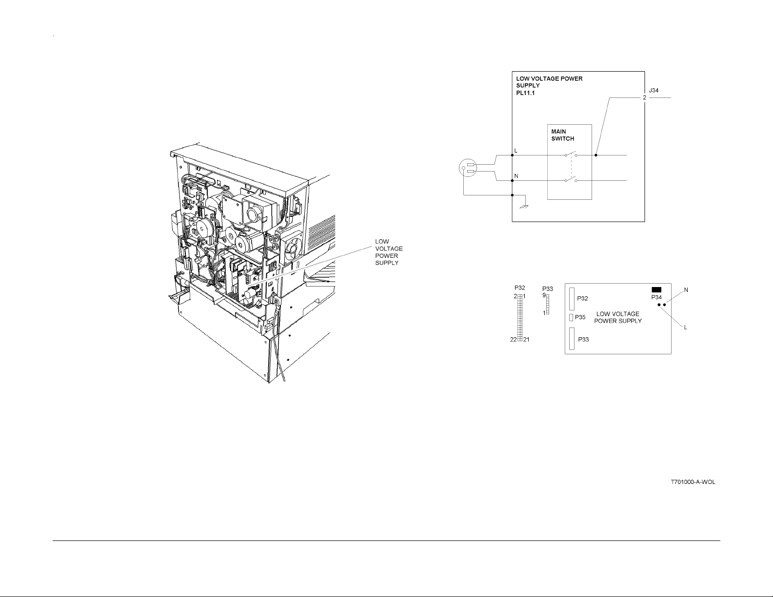
Figure 1 001-701 Circuit Diagram
Status Indicator RAPs
001-701
10/00
2-6
Initial Issue
Phaser 790/DocuColor 2006
Page 21

001-702 +5 VDC Power RAP
Initial Actions
• Ensure AC Power is available at t he wall receptacle.
• Ensure the Power Cord is good. Replace the Power Cord if it is defective (PL 11.1).
Procedure
Switch off the power. Remove the Rear Cover. Switch on the power. +5 VDC is measured
betwe en J33-1 and J33-4.
YN
Switc h off th e pow er. Di sconn ec t J3 2 an d J33 from the Low V o lt ag e Pow er Suppl y. Switch
on the power. +5 VDC is measured between P33-1 and P33-4 on the Low Voltage
Power Supply.
YN
Replace the Low Voltage Power Supply (PL 11.1).
Switch off the power. Reconnect J32 to the Low Voltage Power Supply. Switch on the
power. +5 VD C is measure d between P 33-1 and P3 3-4 on the Lo w Voltage P ower
Supply.
YN
Go to Flag 2. Refer to the +5 VDC Wirenet to troubleshoot a short circuit in the wires
from P32.
Go to Flag 1. Refer to the +5 VDC Wirenet to troubleshoot a short circuit in the wires from
P33.
The Low Voltage Power Supply appears to be operating correctly .
Initial Issue
Phaser 790/DocuColor 2006
10/00
2-7
Status Indicator RAPs
001-702
Page 22
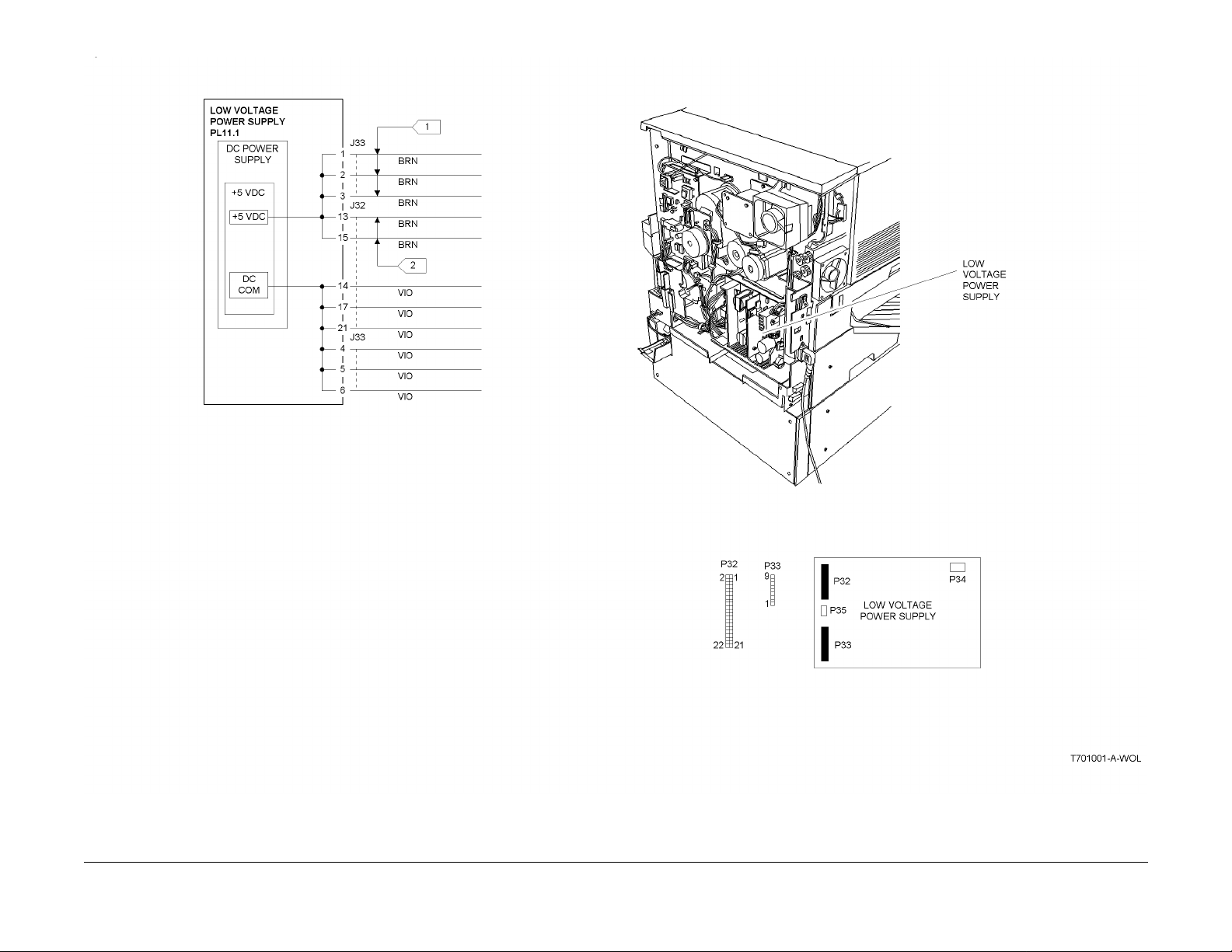
Figure 1 001-702 Circuit Diagram
Status Indicator RAPs
001-702
10/00
2-8
Initial Issue
Phaser 790/DocuColor 2006
Page 23

001-703 +24 VDC Interlocked Power RAP
Initial Actions
Ensure the Left Front Cover, the Registration/Bypass Tray Drawer, and the Main Fuser Assembly are closed and in the correct position.
Ensure that the actuator for the Left Front Cover Interlock is not broken.
Procedure
Switch off the power. Remove the Rear Cover. Switch on the power. +24 VDC is measured
betwe en J32-5 on the Low Voltage Power Supply and mach ine frame.
YN
+5.0 VDC is measured between J32-18 and machine frame.
YN
Approximately +4.4 VDC is measured between J32-16 and machine frame.
YN
Go to Fla g 6. Check th e wire for an open circuit. If the wire is good, replace the
MCU PWB (PL 11.2).
Replace the Low Voltage Power Supply (PL 11.1).
+5.0 VDC is measured between J33-9 on the Low Voltage Power Supply and
machine frame.
YN
+5.0 VDC is measured be tween J199-1 (brown wire) on the Left Front Cover
Interlock and machine frame.
YN
Go to Flag 5. Check the wir e for an open circuit.
+5.0 VDC is measured between J198-1 (yellow wire) on the Left Fron t Cover
Interlock and machine frame.
YN
Replace the Left Front Cover Int erlock ( PL 11.1).
Check the following:
• Go to Flag 2, Flag 3, and Flag 4. Check the wires for an open circuit.
• If the w ires are go od, chec k the conn ectors between th e Low Voltage Po wer
Supply and the Left Front Cover Interl ock for bent or bro ken pin s or for damaged connectors (P/J70, P/J71, P/J97, and P/J91).
Replace the Low Voltage Power Supply (PL 11.1).
The Low Voltage Power Supply appears to be operating correctly .
Initial Issue
Phaser 790/DocuColor 2006
10/00
2-9
Status Indicator RAPs
001-703
Page 24
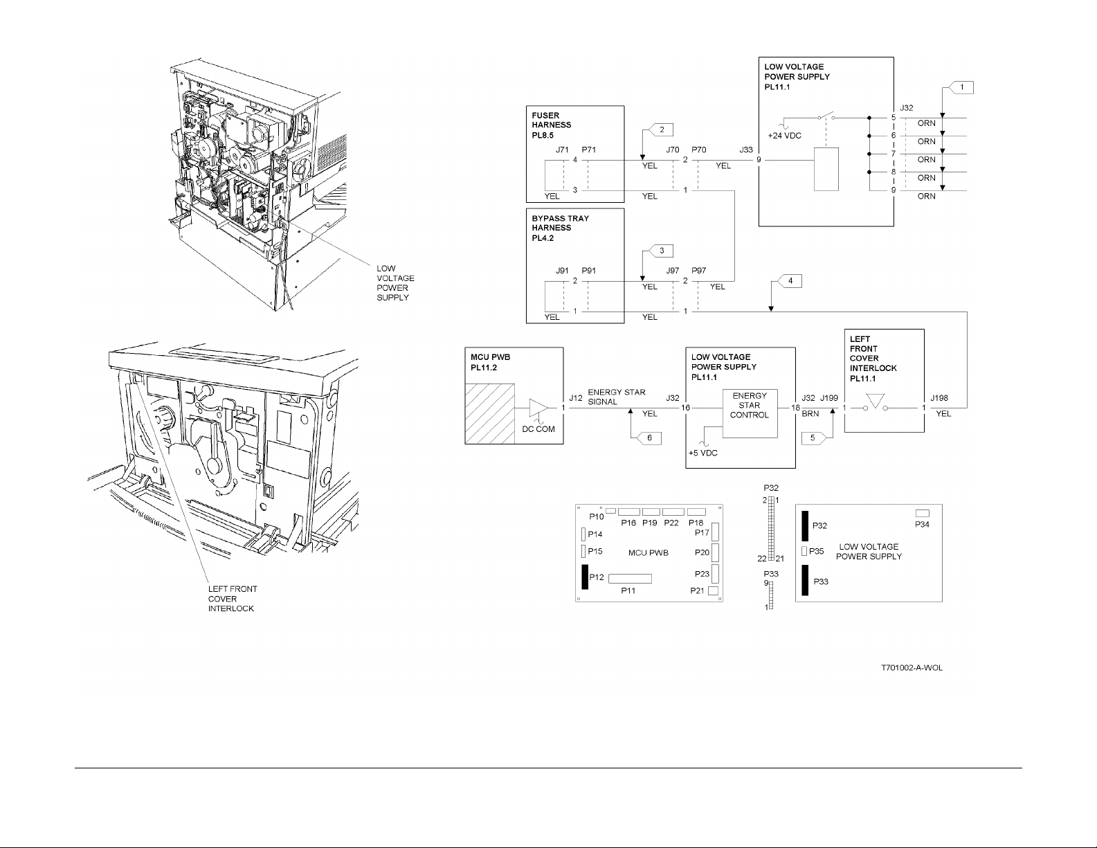
Figure 1 001-703 Circuit Diagram
Status Indicator RAPs
001-703
10/00
2-10
Initial Issue
Phaser 790/DocuColor 2006
Page 25

001-704 Front Cover Open RAP
Initial Actions
Ensure the Right Front Cover is closed and that the actuator for the interlock is not damaged.
Procedure
Access the Digital Input (DI) test from the Control Panel. Enter code [73]. Press the Item/Enter
button. The display indicates 0.
YN
Go to Flag 1 and Flag 2 and check the wires for an open circuit. If the wires are good,
replace the Right Front Cover Interlock (PL 11.2). If the problem continues, replace the
MCU PWB (PL 11.2).
The problem may be intermittent. Go to Flag 1 and Flag 2 and check for loose or damaged
connections or damag ed wires. If the proble m persists, replace the Right Fr ont Cover Interlock
(PL 11.2). If the problem continues, replace the MCU PWB (PL 11.2).
Initial Issue
Phaser 790/DocuColor 2006
10/00
2-11
Status Indicator RAPs
001-704
Page 26
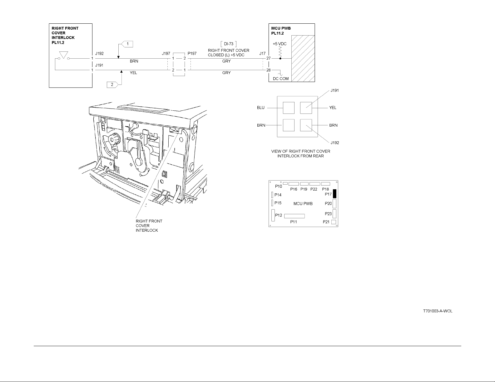
Figure 1 001-704 Circuit Diagram
Status Indicator RAPs
001-704
10/00
2-12
Initial Issue
Phaser 790/DocuColor 2006
Page 27

001-705 ROS +5 VDC Switched Voltage RAP
Initial Actions
Check the following:
• Ensure the Right Front Cover is closed.
• Ensure the Top Cover is correctly pos itioned and is ac tuating the Top Cover Inter lock.
Procedure
Switch off the power. Remove the Rear Cover. Switch on the power. +5 VDC is measured
betwe en J32-22 on the Low Volta ge Power Supply an d machine frame.
YN
Replace the Low Voltage Power Supply (PL 11.1).
Remove the Top Cover. Actuate the T o p Cover Interlock. +5 VDC is measured between
J125-1 on the ROS Assemb ly and machine frame.
YN
With the Top Cover Interl o ck st il l actuated , +5 V DC is measured be t ween FS2 (blue
wire) on the Top Cover Interlock and machine frame.
YN
+5 VDC is measured between FS1 (blue wire) on the Top Cover Interlock and
machine frame.
YN
+5 VDC is measured between J194-1 (bl ue wire) o n the Right Fron t Cover
Interlock and machine frame.
YN
+5 VDC is measured between J193-1 (brown wire) on the Right Front
Cover Interlock and machine frame.
YN
Go to Flag 3. Check the wir e for an open circuit.
Replace the Ri ght Front Cover Interlock (PL 11.2).
Go to Flag 2. Check the wir e for an open circuit.
Replace the Top Cover Interlock (PL 11.1).
Go to Flag 1. Check the wir e for an open circuit.
The ROS +5 VDC Switched circuit appears t o be functioning correctly.
Initial Issue
Phaser 790/DocuColor 2006
10/00
2-13
Status Indicator RAPs
001-705
Page 28
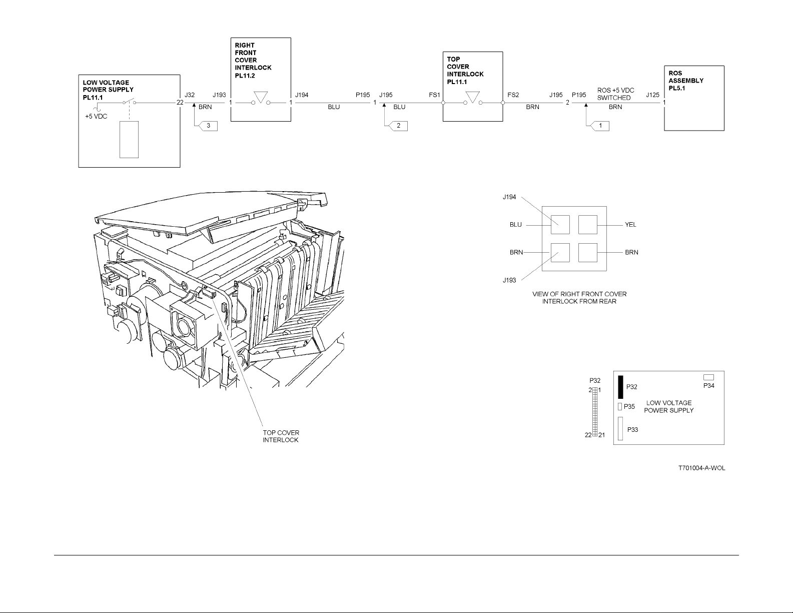
Figure 1 001-705 Circuit Diagram
Status Indicator RAPs
001-705
10/00
2-14
Initial Issue
Phaser 790/DocuColor 2006
Page 29

001-706 Area 1 Open RAP
Initial Actions
Perform the following:
• Check the actuator for the Bypass Tray Interlock. Ensure it is not broken or damaged.
• Ensure the Bypass Tray is clos ed and is in the operating position.
Procedure
Access the Digital Input (DI) test from the Control Panel. Enter code [77]. Press the Item/Enter
button. The display indicates 0.
YN
Go to Flag 1 an d Fl a g 2. Ch ec k the w ire s fo r an op en ci rcu it . If th e wir es are go od , rep la ce
the Bypa ss Tra y Inte rlo ck (PL 4.1 ). If th e pr oble m co ntinu es, r epl ace th e MC U PWB (PL
11.2).
The problem may be intermittent. Go to Flag 1 and Flag 2 and check for loose or damaged
connections or damaged wires. If the problem persists, replace the Bypass Tray Interlock (PL
4.1). If the problem c ontinues, replace the MCU PWB (PL 11.2).
Initial Issue
Phaser 790/DocuColor 2006
10/00
2-15
Status Indicator RAPs
001-706
Page 30
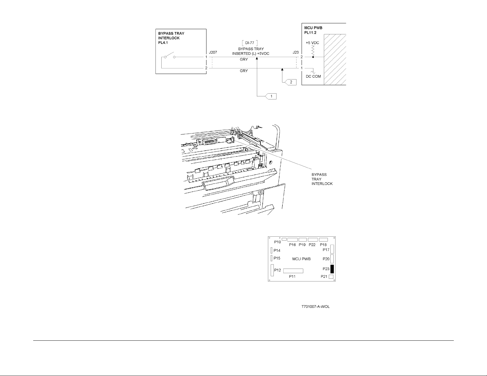
Figure 1 001-706 Circuit Diagram
Status Indicator RAPs
001-706
10/00
2-16
Initial Issue
Phaser 790/DocuColor 2006
Page 31

001-707 Area 2 Open RAP
Initial Actions
Perform the following:
• Check the actuator for the Turn Chute Interl ock. Ensure it is not broken or damaged.
• Ensure the Turn Chute is closed.
Procedure
Access the Digital Input (DI) test from the Control Panel. Enter code [84]. Press the Item/Enter
button. The display indicates 0.
YN
Go to Flag 1 an d Fl a g 2. Ch ec k the w ire s fo r an op en ci rcu it . If th e wir es are go od , rep la ce
the Turn Chute Interl ock (PL 3.3). I f the p roble m cont inues, repla ce th e MCU P WB ( PL
11.2).
The problem may be intermittent. Go to Flag 1 and Flag 2 and check for loose or damaged
connections or damaged wires. If the problem persists, replace the Turn Chute Interlock (PL
3.3). If the problem c ontinues, replace the MCU PWB (PL 11.2).
Initial Issue
Phaser 790/DocuColor 2006
10/00
2-17
Status Indicator RAPs
001-707
Page 32

Figure 1 001-707 Circuit Diagram
Status Indicator RAPs
001-707
10/00
2-18
Initial Issue
Phaser 790/DocuColor 2006
Page 33

001-708 Area 3 Open RAP
Initial Actions
Perform the following:
• Ensure the Right Cover is fully closed.
• Check the actuators for both Feeder Right Cover Switches. Ensure they are not broken or
damaged.
Procedure
Access the Digital Input (DI) test from the Control Panel. Enter code [C0]. Press the Item/Enter
button. The display indicates 0.
YN
Remove the Feeder Rear Cover (PL 13.2). Less than +1.0 VDC is measured between
J217-8 on the Feeder PWB and machine frame.
YN
Go to Flag 1. Check the wires for an open circuit. If the wires are good, replace the
Feeder R ig ht C ov er I nt erlock 1 (PL 13.2).
Replace the Feeder PWB (PL 13.4).
Enter code [C1]. Press the Item/Enter button. The dis pla y in d ica t e s 0.
YN
Remove the Feeder Rear Cover. Less than +1.0 VDC is measured between J217-10
on the F eeder PWB and mach ine frame.
YN
Go to Flag 2. Check the wires for an open circuit. If the wires are good, replace the
Feeder R ig ht C ov er I nt erlock 2 (PL 13.2).
Replace the Feeder PWB (PL 13.4).
The problem may be in ter m i tt e nt. Go t o Fig ur e 1 an d ch ec k f or lo os e or damaged connecti on s
or damag ed wire s. If th e prob lem pers ists, r eplac e the Feed er Ri ght Cove r Inter lock 1 and 2
(PL 13.2). If t he problem continues, r eplace t he Feeder PWB (PL 13.4).
Initial Issue
Phaser 790/DocuColor 2006
10/00
2-19
Status Indicator RAPs
001-708
Page 34

Figure 1 001-708 Circuit Diagram
Status Indicator RAPs
001-708
10/00
2-20
Initial Issue
Phaser 790/DocuColor 2006
Page 35

001-709 Area 4 Open RAP
Initial Actions
Perform the following:
• Check the actuator for the Exit Chute Interlock. Ensure it is not broken or damaged.
• Ensure the Exit Chute is closed.
Procedure
Access the Digital Input (DI) test from the Control Panel. Enter code [74]. Press the Item/Enter
button. The display indicates 0.
YN
Go to Flag 1 an d Fl a g 2. Ch ec k the w ire s fo r an op en ci rcu it . If th e wir es are go od , rep la ce
the Exit Chute Interlock (PL 9.2). If the problem continues, replace the MCU PWB (PL
11.2).
The problem may be intermittent. Go to Flag 1 and Flag 2 and check for loose or damaged
conne ctions or da maged wires. If the proble m persi sts, repl ace the E xit Chute Interloc k (PL
9.2). If the problem c ontinues, replace the MCU PWB (PL 11.2).
Initial Issue
Phaser 790/DocuColor 2006
10/00
2-21
Status Indicator RAPs
001-709
Page 36

Figure 1 001-709 Circuit Diagram
Status Indicator RAPs
001-709
10/00
2-22
Initial Issue
Phaser 790/DocuColor 2006
Page 37

001-710 Area 5 Open RAP
The Control Logic detected that the Fuser Drawer in not fully closed.
Initial Actions
Perform the following:
• Ensure th at the Fuse r Assembl y is fully closed.
• Ensu re tha t the Fu ser As sembl y is mo unted corre ctly an d secur ely. Repai r any ob viou s
defects.
Procedure
Access the Digital Input (DI) test from the Control Panel. Enter code [62]. Press the Item/Enter
button. The display indicates 0.
YN
Go to Flag 1 an d ch eck the wir e for a open circ uit . If t he wir e is good , re plac e th e MC U
PWB (PL 11.2).
The problem may be intermitt ent. Go to Flag 1 and check for loose o r damaged connections or
damage d wires. If the problem persists, replace the MCU PWB (PL 11.2).
Initial Issue
Phaser 790/DocuColor 2006
10/00
2-23
Status Indicator RAPs
001-710
Page 38

Figure 1 001-710 Circuit Diagram
Status Indicator RAPs
001-710
10/00
2-24
Initial Issue
Phaser 790/DocuColor 2006
Page 39

001-711 Area 6 Open RAP
The Control Logic has detected that area 6 is open.
Initial Actions
Perform the following:
• Ensure that the I nverter Chute (PL 15.5) is fully closed.
• Ensure that the actuator for the CAB Interlock is not broken. Repair any obvious defects.
Procedure
Access the Digital Input (DI) test from the Control Panel. Enter code [93]. Press the Item/Enter
button. The display indicates 0.
YN
Go to Flag 1 and Flag 2. Check the wires for a open circuit. If the wires are good, replace
the Duplex Controller PWB (PL 15.6).
The problem may be intermittent. Go to Flag 1 and Flag 2 and check for loose or damaged
connections or da maged wires. If the problem pers ists, replace the replace the Duplex Controller PWB (PL 15.6).
Initial Issue
Phaser 790/DocuColor 2006
10/00
2-25
Status Indicator RAPs
001-711
Page 40

Figure 1 001-711 Circuit Diagram
Status Indicator RAPs
001-711
10/00
2-26
Initial Issue
Phaser 790/DocuColor 2006
Page 41

001-712 IIT DC Power RAP
Initial Actions
Ensure AC power is avail able at the wall outlet.
Ensure that the AC Power Cor d is securely connected to the system.
Procedure
Remove the Rear Cover (REP 6.4) from the IIT. Check the following voltages at P91 (Figure 1)
on the IIT LVPS:
• P91-1 (Orange Wire) for +24 VDC
• P91-2 (Orange Wire) for +24 VDC
• P91-3 (Gray Wire) for +5 VDC
• P91-4 (Gray Wire) for +3.5 VDC
All of the vol t ag e ar e av ai lable.
YN
All of the voltages are missing.
YN
Check th e pi ns on conn ect o r P/ J91. Loo k f or lo ose or da mag ed pins. If the co nn ec tor
is OK, replace the IIT LVPS (PL 16.1).
Check the Fuse (Figure 1) on the IIT LVPS. The Fuse is defective.
YN
AC line voltage is available between JN1-1 an d JN1-2 (Figure 1).
YN
Replace the AC Switch/Harness (PL 16.6).
Replace the IIT LVPS (P L 16.1).
Replace the Fuse. If the Fuse blows again, replace the IIT LVPS (PL 16.1).
Go to the wirenets to check for any wires that may be open.
Check the IIT LVPS connectors for any loose or da maged pi ns.
Initial Issue
Phaser 790/DocuColor 2006
10/00
2-27
Status Indicator RAPs
001-712
Page 42

Figure 1 001-712 Circuit Diagram
Status Indicator RAPs
001-712
10/00
2-28
Initial Issue
Phaser 790/DocuColor 2006
Page 43

002-310 IIT Control Panel Failure RAP
The IIT Con tr o l Pa ne l ha s failed.
Procedure
Check th e cabl e betwee n the ICM M ain PWB and the C ontrol Pa nel for an y pinche d wires.
Check the connectors fo r any loose or damaged pins. If the harness and connectors are good,
replace the Control Panel Assembly (PL 16.6).
002-701 Blank/Garbled IOT Display RAP
Initial Actions
Remove the Right Cover (REP 14.9) in order to check the LEDs on the ESS PWB (Figure 1).
LED D5 (r ed LED) should not be lit and LED D4 (green LED ) should be lit. If LED D5 is l it, or is
flashing, replace the ESS PWB (PL 12.1).
Procedure
The Control Panel is blank.
YN
Reseat the Panel Harness between the ESS PWB and the Control Panel. If the problem
continues, replace the following components in the order listed until the problem is
resolved:
• Panel Harne ss (PL 12.1)
• Control Panel (PL 1.2)
• ESS PWB (PL 12.1)
NOTE: The following voltage measurement is made at the solder points for J11 on the ESS
PWB. Refer to the Cir cuit Diagram for the correct location to make the measurements.
+5 VDC is measured between J11 pins A1, A2, B1, and B2 on the ESS PWB to machine
frame.
YN
Go to the 001-702 +5 VDC Power RAP.
Reseat the Panel Harness between the ESS PWB and the Control Panel. If the problem continues , replace the followi ng compon ents in the order listed until the problem is resolved:
• Panel Har ness (PL 12.1)
• Control Panel (PL 1.2)
• ESS PWB (PL 12.1)
Initial Issue
Phaser 790/DocuColor 2006
10/00
2-29
Status Indicator RAPs
002-310, 002-701
Page 44

Figure 1 002-701 Circuit Diagram
Status Indicator RAPs
002-701
10/00
2-30
Initial Issue
Phaser 790/DocuColor 2006
Page 45

002-702 IOT Control Panel Button/LED RAP
Initial Actions
Reseat the connectors on the cable between the ESS PWB and the Control Panel (P/J34 and
P/J 317. Check for any loose or damaged pins in the harness connectors.
Procedure
Ensure that the Initial Actions has been performed. If the problem continues, replace the Control Panel (PL 1.2). If the problem continues, replace the ESS PWB (PL 12.1).
Initial Issue
Phaser 790/DocuColor 2006
10/00
2-31
Status Indicator RAPs
002-702
Page 46

Status Indicator RAPs
002-702
10/00
2-32
Initial Issue
Phaser 790/DocuColor 2006
Page 47

003-310 Feeder Communications Failure RAP
The Control Logic detected a communication failure with the Feeder PWB.
Initial Actions
• Ensure that connector P/J 212 is properly seated on the Fe eder PWB.
• Remove the ESS PW B (R EP 1.9 ) and ch eck the P/J 22 on t he MCU PW B. En su re tha t it
is properly seated on the PWB.
Procedure
Perform the following:
• Go to Flag 1. Check the wires between the Feeder PWB and the MCU PWB for an open
circuit.
• If the prev ious check is OK, rep lace the Feed er PWB (P L 13 .4 ) .
• If the problem continues, replace the MCU PWB (PL 11.2).
Initial Issue
Phaser 790/DocuColor 2006
10/00
2-33
Status Indicator RAPs
003-310
Page 48

Figure 1 003-310 RAP Cir c uit Diagram
Status Indicator RAPs
003-310
10/00
2-34
Initial Issue
Phaser 790/DocuColor 2006
Page 49

003-311 Duplex Communications Failure RAP
The Control Logic detected a communication failure with the Duplex Controller PWB.
Initial Actions
• Ensure that connector P/J 142 is properly seated on the Duplex Controller PWB.
• Remove the ESS PW B (R EP 1.9 ) and ch eck the P/J 22 on t he MCU PW B. En su re tha t it
is properly seated on the PWB.
Procedure
Perform the following:
• Go to Flag 1. Check the wires between the Duplex Controller PWB and the MCU PWB for
an open circuit.
• If the previous check is OK, replace the Duplex Co ntroller PWB (PL 15.6).
• If the problem continues, replace the MCU PWB (PL 11.2).
Initial Issue
Phaser 790/DocuColor 2006
10/00
2-35
Status Indicator RAPs
003-311
Page 50

Figure 1 003-311 RAP Circuit Diagram
Status Indicator RAPs
003-311
10/00
2-36
Initial Issue
Phaser 790/DocuColor 2006
Page 51

003-312 Sorter Communications Failure RAP
The Sorter Control Logic did not successfully receive the Start signal from the MCU PWB.
Procedure
Go to Flag 1 and check the wires for an open or short circ uit. The wires are good.
YN
Repair the wires.
Replace the Sorter Control PWB (PL 19.1). If the problem continues, replace the MCU PWB
(PL 11.2)
Initial Issue
Phaser 790/DocuColor 2006
10/00
2-37
Status Indicator RAPs
003-312
Page 52

Figure 1 003-311 RAP Circuit Diagram
Status Indicator RAPs
003-312
10/00
2-38
Initial Issue
Phaser 790/DocuColor 2006
Page 53

003-333 Foreign Interface RAP
This Fault C o de in di cate s tha t a c om m unic at ions fa ilure w as d ete cted b etwe en th e ESS P WB
and the Foreign Interface.
Procedure
Switch the IOT power off, then on. Fault Code 003- 333 is still present.
YN
If interm it te nt pe rf o rmance is susp ected, per for m t he foll ow i ng:
• Check the connections between the ESS PWB and the Foreign Interface and the
interconnecting harness.
• Reseat the P/J 17 connector on the ESS PWB and P/J 905 on the Foreign Interface.
Go to Flag 1 and check the wires for an open or short circ uit. The wires are good.
YN
Repair the wires.
There is +5 VDC between J905-8 and machine fram e.
YN
There is +5 VDC between J 17-7 and machine frame.
YN
Replace the ESS PWB (PL 12.1).
Go to Flag 2 and check the wire for an open circuit.
Go to Flag 3 and check the wires for an open or short circ uit. The wires are good.
YN
Repair the wires.
Replace the ES S PWB (PL 12 .1). If the problem continues, replace the Fo reign Interfac e.
Initial Issue
Phaser 790/DocuColor 2006
10/00
2-39
Status Indicator RAPs
003-333
Page 54

Figure 1 003-333 RAP Cir c uit Diagram
Status Indicator RAPs
003-333
10/00
2-40
Initial Issue
Phaser 790/DocuColor 2006
Page 55

003-334 Foreign Interface Compatibility RAP
This Fa ult Co de ind icates that a com patibil ity p roblem was detecte d bet ween t he ESS PWB
and the Foreign Interface (an incorrect Foreign Interface device may be installed).
Procedure
Switch the IOT power off, then on. Fault Code 003- 334 is still present.
YN
If interm it te nt pe rf o rmance is susp ected, per for m t he foll ow i ng:
• Check the connections between the ESS PWB and the Foreign Interface and the
interconnecting harness.
• Reseat the P/J 17 connector on the ESS PWB and P/J 905 on the Foreign Interface.
The Foreign Interface device is the correct device for the P790/DC2006.
YN
Install the corre ct Fo rei gn Inter face .
Go to Flag 1 and check the wires for an open or short circ uit. The wires are good.
YN
Repair the wires.
Replace the Foreign Interface.
Initial Issue
Phaser 790/DocuColor 2006
10/00
2-41
Status Indicator RAPs
003-334
Page 56

Figure 1 003-334 RAP Cir c uit Diagram
Status Indicator RAPs
003-334
10/00
2-42
Initial Issue
Phaser 790/DocuColor 2006
Page 57

003-356 IOT NVM RAM Error RAP
The system detected an IOT NV RAM error at power on.
Procedure
Switch the power off then switch the power on. The fault code occurs.
YN
If the proble m seems to be in termittent , reseat all con nectors on th e MCU PWB. If the
problem occurs again, replace the MCU P WB (PL 11.2).
Go to Flag 1. Check the wires for an open or short circuit. If the wires are good, replace the
Communication PWB. If the probl em continues, rep lace the MC U PWB (PL 11.2).
Initial Issue
Phaser 790/DocuColor 2006
10/00
2-43
Status Indicator RAPs
003-356
Page 58

Figure 1 003-356 RAP Cir c uit Diagram
Status Indicator RAPs
003-356
10/00
2-44
Initial Issue
Phaser 790/DocuColor 2006
Page 59

003-400 IOT Firmware Error RAP
The system detected a n IOT firmware error.
003-701 Copy/Print Cartridge Error RAP
The Control Logic detected an error with the Copy/Print Cartridge CRUM.
Procedure
Switch the power off then switch the power on. The Fault Co de occurs.
YN
If the proble m seems to be in termittent , reseat all con nectors on th e MCU PWB. If the
problem occurs again, Perform GP 8, IOT Software Installation. If the problem is still not
resolved, replace the MCU PWB (PL 11.2).
Perform GP 8, IOT Software Installation. If the problem continues, replace the MCU PWB (PL
11.2).
Initial Actions
• If the Copy/Print Cartridge is due to be replaced, refer to REP 9.1 and replace the cartridge.
• Check the CRUM connector on the Copy/Print Ca rtridge. Ensure that the contacts are
clean an d not dam aged. Replace the Copy/ Print Cartridge if required (PL 5.1) .
Procedure
Perform the following:
• Go to Flag 1 and che ck the co nn ect or s on th e MCU PWB, P/J 84, an d on t he CRU M Connector.
• If the previous check is OK, replace the MCU PWB (PL 11.2).
Initial Issue
Phaser 790/DocuColor 2006
10/00
2-45
Status Indicator RAPs
003-400, 003-701
Page 60
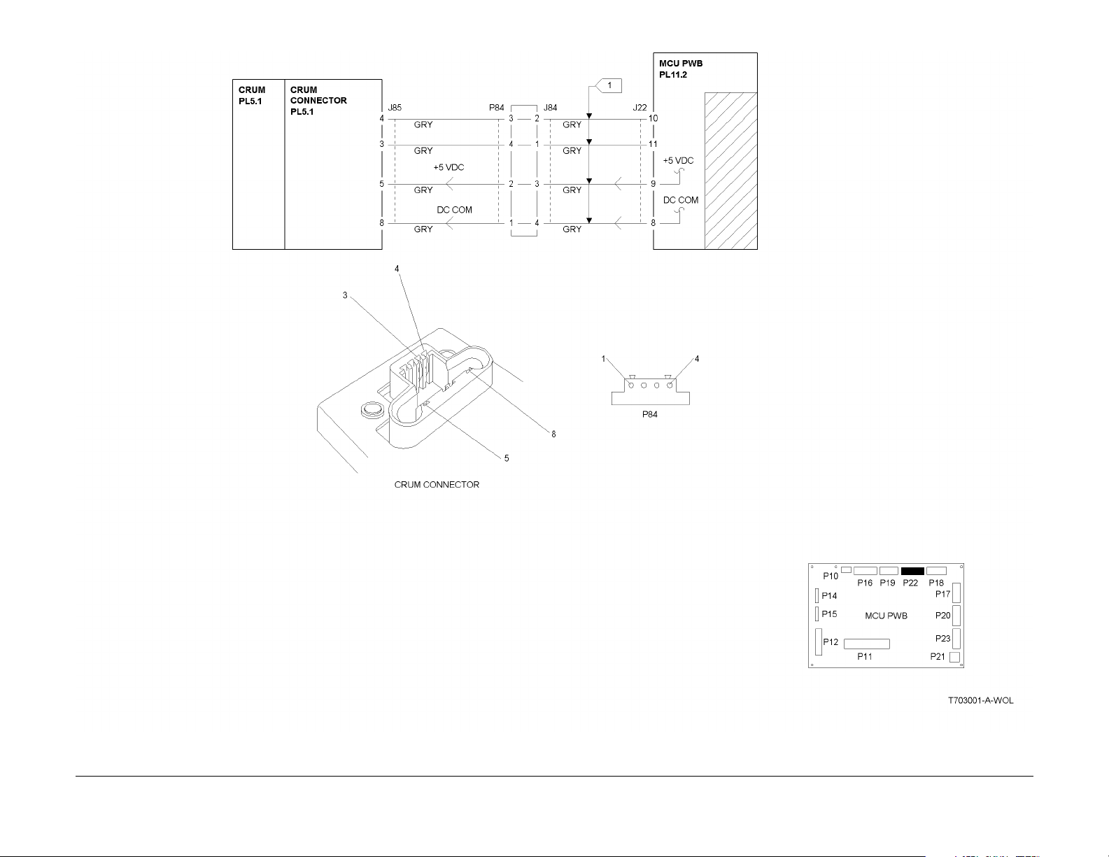
Figure 1 003-701 RAP Cir c uit Diagram
Status Indicator RAPs
003-701
10/00
2-46
Initial Issue
Phaser 790/DocuColor 2006
Page 61

004-320 Paper Handling Motor RAP
The Control Lo gic detected that the Paper Handling Motor is not functionin g.
Initial Actions
Check the connectors on the Drive Motor PW B. Ensure that th ey are cor rectly seated.
Procedure
Switc h off the power then switch on the power. The 04-32 0 fa u l t co d e is declar ed at th e end
of self-test.
YN
Go to Fl ag 2 a nd ch eck the h arn ess betw een t he D rive M ot or PW B and th e Pap er Ha ndling M otor f or da mag ed w ires o r co nnec tor pins . If th e wir es ar e OK, repl ace t he Paper
Handling Motor (PL 10.1). If the problem continues, replace the Drive Motor PWB (PL
10.1).
Access the Dig ital Outpu t (DO) test from th e Control Pane l. Enter co de [53]. Press the Item/
Enter button. The Paper Handling Motor e nergizes.
YN
Access the DO Stop Test from the Control Panel. Enter code [53]. Press the Item/Enter
button. +5 VDC is me asured be tween J5 0-2 on the Driv e Motor PW B and machin e
frame.
YN
Go to Fl ag 3 a nd ch ec k the wire s for an o pen c irc uit. I f th e wi res ar e go od, r epl ace
the MCU PWB (PL 11.2).
Access the Dig ital Output (DO) test from the Cont rol Panel. Enter code [53]. Press the
Item/Enter button. The voltage at J50-2 goes to less than +1.0 VDC
YN
Replace the MCU PWB (PL 11.2).
+24 VDC is measur ed between J49-2 on the Drive Motor PWB and machine frame.
YN
Go to Flag 4 and check the wires for an open circuit (refer to the +24 VDC Interlocked Wirenet).
Go to Fl ag 2 a nd ch eck the h arn ess betw een t he D rive M ot or PW B and th e Pap er Ha ndling M otor f or da mag ed w ires o r co nnec tor pins . If th e wir es ar e OK, repl ace t he Paper
Handling Motor (PL 10.1). If the problem continues, replace the Drive Motor PWB (PL
10.1). If the problem can not be resolved, replace the MCU PWB (PL 11.1)
Check the following:
• Go to Flag 1 and check the wire for an open circuit.
• Go to Fl ag 2 and chec k th e har nes s be twee n the Driv e Mo tor PWB a nd th e Pa per H an-
dling Motor for damaged w ires or co nnector pins.
• The proble m may be in te rmi tt e nt. Go to Fi gu re 1 an d ch eck for lo os e or da mag ed conn ec tions or damaged wires. If the problem persists, replace the replace the MCU PWB (PL
11.2).
Initial Issue
Phaser 790/DocuColor 2006
10/00
2-47
Status Indicator RAPs
004-320
Page 62

Figure 1 004-320 RAP Cir c uit Diagram
Status Indicator RAPs
004-320
10/00
2-48
Initial Issue
Phaser 790/DocuColor 2006
Page 63

004-322 Fuser Motor RAP
The Control Logic detected that the Fuser Motor is not functioning.
Initial Actions
Check the conn ecto r s on the Driv e Moto r PWB an d the Fu se r Moto r. Ensure that th ey are c orrectly se ated.
Procedure
Switc h off the power then switch on the power. The 04-32 2 fa u l t co d e is declar ed at th e end
of self-test.
YN
Go to Flag 2 and check the harness between the Drive Motor PWB and the Fuser Motor
for dama ged, or l oose, wi res or co nnector pin s. If the wires a re OK, rep lace the F user
Motor ( PL 10.1) . If the problem continues, replace the Drive Motor PWB (PL 10.1).
Access the Dig ital Outpu t (DO) test from th e Control Pane l. Enter co de [53]. Press the Item/
Enter button. The Fuser Motor energizes.
YN
Go to Flag 2 and check the harness between the Drive Motor PWB and the Fuser Motor
for damaged wires or connector pins. If the wires are OK, replace the Fuser Motor (PL
10.1). If the prob lem co ntin ues, re plac e the D rive Motor PWB ( PL 10 .1). I f the proble m
can not be resolved, replace the MCU PWB (PL 11.1)
Check the following:
• Go to Flag 1 and check the wire for an open circuit.
• Go to Flag 2 and check the harness between the Drive Motor PWB and the Fuser Motor
for damaged wires or conn ector pins.
• The proble m may be in te rmi tt e nt. Go to Fi gu re 1 an d ch eck for lo os e or da mag ed conn ec tions or damaged wires. If the problem persists, replace the replace the MCU PWB (PL
11.2).
Initial Issue
Phaser 790/DocuColor 2006
10/00
2-49
Status Indicator RAPs
004-322
Page 64

Figure 1 004-322 RAP Cir c uit Diagram
Status Indicator RAPs
004-322
10/00
2-50
Initial Issue
Phaser 790/DocuColor 2006
Page 65

005-210 Nudger Home RAP
The signal, Nudger Home (L), is not detected within 1 second after ADF Drive Motor is energized.
Procedure
Switch off the power. Remove the ADF Rear Cover. Observe the Nudger Roll as the power is
switc he d on . The Nudger Roll Rotates.
YN
The ADF Drive Motor energized.
YN
Switch off the power. Disconnect the belt from the ADF Drive Motor. Switch on the
power The ADF Drive Motor energizes.
YN
There is +24 VDC from pin 1 and from pin 6 of J 812 to frame ground.
YN
Replace the ADF Control PWB (PL 17.2).
Go to F lag 3. C heck for bro ken w ires, or dama ged pin s at J 81 2. If the wires
and con ne c tor are OK, re p lac e the ADF Cont ro l P W B (PL 17.2). If the pr ob le m
continues, replace the ADF Drive Motor (PL 17.2).
Check for binding or damage to the one-way Pulleys (PL 17.2).
Check for loose or damaged Belts or Pulleys (PL 17.2, PL 17.3).
Remove the ADF Front Cover (PL 17.1). Block and unblock the Nudger Home Sensor as you
monitor the voltage from J 814 pin 8 to frame ground. The vol tag e is + 5 VDC wh en th e se n-
sor is blocked and less than 1 VDC when the sensor is not blocked.
YN
The voltage is always less than 1 VDC
YN
Disconnect P/J 713. There is +5 VDC from pin 1 to pin 3 on J 7 13.
YN
There is +5 VDC from pin 9 to pin 7 on J 814
YN
Go to Flag 2. Check for a short circuit. If the wires are OK, replace the
ADF Control PWB (PL 17.2).
A
Check that the Actuator for the Nudger Home Sensor (PL 17.3) is installed correctly and is free
from damage. If the Actuator is OK, replace the ADF Control PWB (PL 17.2).
Go to Flag 2. Check for an open circuit.
Replace the Nudger Home Sensor (PL 17.3 ).
Disconnect P/J 713. The voltage changes to +5 VDC .
YN
Go to Fl ag 1. Che ck for a s ho rt circuit to ground. If the w ire is OK, replace th e ADF
Control PWB (PL 17.2).
Replace the Nudger Home Sensor (PL 17.3 ).
A
Initial Issue
Phaser 790/DocuColor 2006
10/00
2-51
Status Indicator RAPs
005-210
Page 66

NUDGER ROLL
Status Indicator RAPs
005-210
Figure 1 005-210 RAP Cir c uit Diagram
10/00
2-52
Initial Issue
Phaser 790/DocuColor 2006
Page 67

005-211 ADF Power RAP
ADF Motor Power Error
Procedure
Remove the ADF Rear Cover. There is +24 VDC from pin 11 to pin 12 on J811.
YN
Go to Flag 1. Check for an open circuit. If the wires are OK, go to the 001-712 RAP.
Check the fuse on the ADF Control PWB (PL 17.2). If the Fuse is OK, replace the ADF Control
PWB (PL 17.2).
Initial Issue
Phaser 790/DocuColor 2006
10/00
2-53
Status Indicator RAPs
005-211
Page 68

Figure 1 005-211 RAP Circuit Diagram
Status Indicator RAPs
005-211
10/00
2-54
Initial Issue
Phaser 790/DocuColor 2006
Page 69

005-220/221 ADF Communications RAP
ADF Communication Error
Procedure
There is +5 VDC from pin 9 to pin 10 on J811.
YN
Go to Flag 4. Check for an open circuit. If the wires are OK, replace the ICM Main PWB
(PL 16.2).
Switch off the power. Remove the ADF Rear Cover. Switch on the power. The red LED (CR2)
flashes when power is switched on.
YN
Go to Flag 3. Check for an open circuit. If the wire is OK, replace the ADF Control PWB
(PL 17.2). If the problem persists, replace the ICM Main PWB (PL 16.2).
Switc h off the power then switch on the power. The green LED (CR3) flashes when power is
switche d o n.
YN
Go to Flag 1. Check for an open circuit. If the wires are OK, repl ace th e ADF Control PWB
(PL 17.2). If the problem persists, replace the ICM Main PWB (PL 16.2).
Go to Flag 2. Check for an open circuit. If the wires are OK, replace t he ADF Cont rol PWB (PL
17.2). If the problem persists, replace the ICM Main PWB (PL 16.2).
Initial Issue
Phaser 790/DocuColor 2006
10/00
2-55
Status Indicator RAPs
005-220/221
Page 70

Figure 1 005-220/221 RAP Circuit Diagram
Status Indicator RAPs
005-220/221
10/00
2-56
Initial Issue
Phaser 790/DocuColor 2006
Page 71

005-700 ADF Fault Entry RAP
Procedure
Use the following table to troubleshoot ADF problems that do not generate a fault code.
Table 1
Problem desc ript i on Troubleshooting
ADF not recognized. Cop ies made from Platen
Glass even with documents in the Entrance Tray
Entrance Jam. First sheet of set jammed in Registration Chute.
Exit Jam. First Sheet of set stalled on glass or
jammed in Exit Chute.
Incomplete copy job. Copy job is never finished.
Documents may or may not reci rculate. IIT display
never returns to READY TO COPY.
Go to the 005-7 03 RAP
Go to the 005-7 01 RAP
Go to the 005-7 02 RAP
Go to the 005-7 04 RAP
Initial Issue
Phaser 790/DocuColor 2006
10/00
2-57
Status Indicator RAPs
005-700
Page 72

005-701 ADF Entrance Jam RAP
Procedure
The green LED of the Document Set Indicator is always lit.
YN
Remove the ADF Rear Cover. There is +5 VDC from J 814 pin 5 to frame ground.
YN
Disconnect P/J 712. There is +5 VD C from J 814 pin 5 to frame ground.
YN
Go to F la g 4. C he ck fo r a s ho rt c ircu it. If the wire is O K, re pl ace th e ADF Control PWB (PL 17.2).
Replace the ADF Registration Sensor (PL 17.5).
Open the Upper Chute Cover. Insert a sheet of paper into the Registration Chute until it
blocks the ADF Registration Sensor. There is less than 1 VDC from J 814 pin 5 to
frame ground.
YN
There is +5 VDC from pin 6 to pin 4 of J814.
YN
Replace the ADF Control PWB (PL 17.2).
There is +5 VDC from pin 1 to pin 3 of J 712.
YN
Go to Flag 5. Check for an open circuit.
Replace the ADF Registration Sensor (PL 17.5)
A
There is +5 VDC from pin 3 to pin 1 of J814.
YN
Replace the ADF Control PWB (PL 17.2).
There is +5 VDC from pin 1 to pin 3 of J 711.
YN
Go to Flag 2. Check f or an open circuit.
Disconnect P/J 711. There is +5 VDC from J 814 pin 2 to frame ground.
YN
Go to Flag 1. Check for a short circuit. If the wire is OK, replace the ADF Control PWB (PL
17.2).
Replace the Document Set Sensor (PL 17.5).
The Gea r (PL 17.3) on the outb oard end of the Feed Roll (REP 5. 4) and the Pulley ( PL
17.2) on the inboard end of the Nudger Roll (REP 5.5) contain on e-way clutches. Ensu res
that these parts are installed correctly, and that the clutch functions per the descriptions in
the repair procedures. The Gear and Pulley are OK.
YN
Clean, repair, reinstall or replace as required.
Check the following for wear, damage, or dirt:
• Drive Belts (PL 17.2)
• Feed Roll ( PL 17 .3)
• Registration Roll (PL 17.3)
• Retard Rolls (PL 17.4)
• Platen Belt, Be arings, and Dr ive Gear (PL 17.6).
• Ensure that the Nudger Chute (PL 17.4) moves freely.
The checks are g ood.
YN
Clean, repair, or replace as required.
Go to F lag 3. C heck for broke n wire s or loos e pin s. If the pro bl em co ntin ues r epl ace th e
ADF Control PWB (PL 17.2).
If the problem remains, replace the ADF Drive Motor (PL 17.2).
A
Status Indicator RAPs
005-701
10/00
2-58
Initial Issue
Phaser 790/DocuColor 2006
Page 73

Figure 1 005-701 RAP Cir c uit Diagram
Initial Issue
Phaser 790/DocuColor 2006
10/00
2-59
Status Indicator RAPs
005-701
Page 74

005-702 ADF Exit Jam RAP
Procedure
Remove the ADF Rear Cover. Enter Copy mode. Place a sheet of paper into the Entrance
Tray. Press the Start button. The ADF Exit Motor energizes.
YN
Switch off the power. Disconnect the belt from the ADF Exit Motor. Switch on the power
The ADF Exit Motor energizes.
YN
There is +24 VDC from pin 1 and from pin 6 of J 813 to frame ground.
YN
Replace the ADF Control PWB (PL 17.2).
Go to Flag 3. Check for broken wires, or damaged pins at J 813. If the wires and
conne ctor ar e OK, r eplac e the AD F Con trol P WB (P L 17. 2). If the prob lem co ntinues, replace the ADF Exit Motor (PL 17.7).
Check for binding or da mage to the Upper and Lower Exit Rolls and Bearings.(PL 17.7).
There is +5 VDC from J 815 pin 2 to frame ground.
YN
Disconnect P/J 718. There is +5 VD C from J 815 pin 2 to frame ground.
YN
Go to Flag 1. Check fo r a short circ uit. If the w ire is OK, re place the AD F Control
PWB (PL 17.2).
Replace the ADF Exit Sensor (PL 17.7).
Remove th e Ex it C h ute Cover (PL 17.7). Press and h old th e ac t u at or fo r the AD F E x it S en so r.
There is less than 1 VDC from J 815 pin 2 to frame ground.
YN
There is +5 VDC from pin 3 to pin 1 of J 815.
YN
Replace the ADF Control PWB (PL 17.2).
There is +5 VDC from pin 1 to pin 3 of J 718.
YN
Go to Flag 2. Check for an open circuit.
Replace the ADF Exit Sensor (PL 17.7).
Check for the following conditions (PL 17.7):
• Worn or dirty Exit Rolls
• Damaged or missing Pinch Rolls
• Damaged or incorrectly installed Antistatic Brush
• Blockage or damage to the E x it Chute.
• Wear or damage to the Exi t R oll Pulleys or B elt
Status Indicator RAPs
005-702
10/00
2-60
Initial Issue
Phaser 790/DocuColor 2006
Page 75

Figure 1 005-702 RAP Cir c uit Diagram
EXIT SENSOR
EXIT MOTOR
Initial Issue
Phaser 790/DocuColor 2006
10/00
2-61
Status Indicator RAPs
005-702
Page 76

005-703 ADF No Feed RAP
Procedure
Open, then close the Upper Chute Cover . The ADF Drive Motor cycles.
YN
Go to Flag 3. Check for an open circuit. If the wire is OK, replace the ADF Control PWB
(PL 17.2). If the problem remains, replace the ICM Main PWB (PL 16.2).
Use a test lead or a jumper w ire to short J 814 pin 2 to ground. The Document Set Indica-
tor lights.
YN
Replace the ADF Control PWB (PL 17.2).
Disconnect P/J 711. There is +5 VDC from pin 2 of J711 to frame ground.
YN
Go to Flag 1. Check for an open circuit.
There is +5 VDC from pin 1 to pin 3 of J711.
YN
Go to Flag 2. Check for an open circuit.
Replace the Document S et Sensor (PL 17.5).
Status Indicator RAPs
005-703
10/00
2-62
Initial Issue
Phaser 790/DocuColor 2006
Page 77

Figure 1 005-703 RAP Cir c uit Diagram
Initial Issue
Phaser 790/DocuColor 2006
10/00
2-63
Status Indicator RAPs
005-703
Page 78

005-704 Unfinished Copy Job RAP
Procedure
Go to Flag 1 and Flag 2. Check the wires for an open circuit. If the wires are OK, replace the
ICM Main PWB (PL 16.2).
Status Indicator RAPs
005-704
10/00
2-64
Initial Issue
Phaser 790/DocuColor 2006
Page 79

Figure 1 005-704 RAP Cir c uit Diagram
Initial Issue
Phaser 790/DocuColor 2006
10/00
2-65
Status Indicator RAPs
005-704
Page 80

Status Indicator RAPs
005-704
10/00
2-66
Initial Issue
Phaser 790/DocuColor 2006
Page 81

006-310 IIT Registration RAP
The Cont rol Logic has not d ete cted the s igna l II T Reg istra ti on Sen sor Sens ed (H ) + 5 VD C at
the correct time.
Initial Actions
Check the Carriage Motor drive components, including the Belt (PL 16.4) and the Front and
Rear Cables (PL 16.4) .
Procedure
Switch off the power. Disconnect the power cord. Remove the IIT Rear Cover (REP 6.4).
Remove the IIT Right Cover (REP 6.2). Disconnect P/J 110 (Carriage Motor connector) from
the ICM Main PWB. Turn the bronze flywheel on the Carriage Motor ia a CW direction in order
to drive the Carriage all the way to the right (as viewed from the rear of the IIT). Connect the
power cord and switch on the power. +5 VDC is measured at P 130-8 to frame.
YN
Go to Fl ag 1 . Check th e w ire for a sh or t c ir c ui t t o ground. If the wire i s go od , r e pl ac e the
IIT Registration Sensor (PL 16.1).
While monitoring the voltage a P/J 130-8, turn the flywheel CCW. The voltage at P/J130-8
goes to less than +1.0 VDC.
YN
Go to Flag 1 an d Fl a g 2. Ch ec k the w ire s fo r an op en ci rcu it . If th e wir es are go od , rep la ce
the IIT Registration Sensor (PL 16.1).
Switch off the po wer. Disconne ct the p ower cor d. Recon nect P/J 110. Switch on the powe r.
+24 VDC is measur ed at P/ J110-1 and P/J110- 2 to frame.
YN
Replace the ICM Main PWB (PL 16.2).
+24 VDC is measur ed at P/ J 130-3, P/J130-4, P/J130-5, and P/J130-6 to f rame.
YN
Go to Flag 3. Check the wires for an open circuit. If the wires are good, replace the Carriage Motor.
The probl em see ms t o be int erm itten t. Go t o Flag 1, Flag 2, and F la g 3. Check al l co nnec tors
for loose or damaged pins. If the problem continues, replace the IIT Registration Sensor (PL
16.1). If the problem continues, replace the ICM Main PWB (PL 16.2).
Initial Issue
Phaser 790/DocuColor 2006
10/00
2-67
Status Indicator RAPs
006-310
Page 82
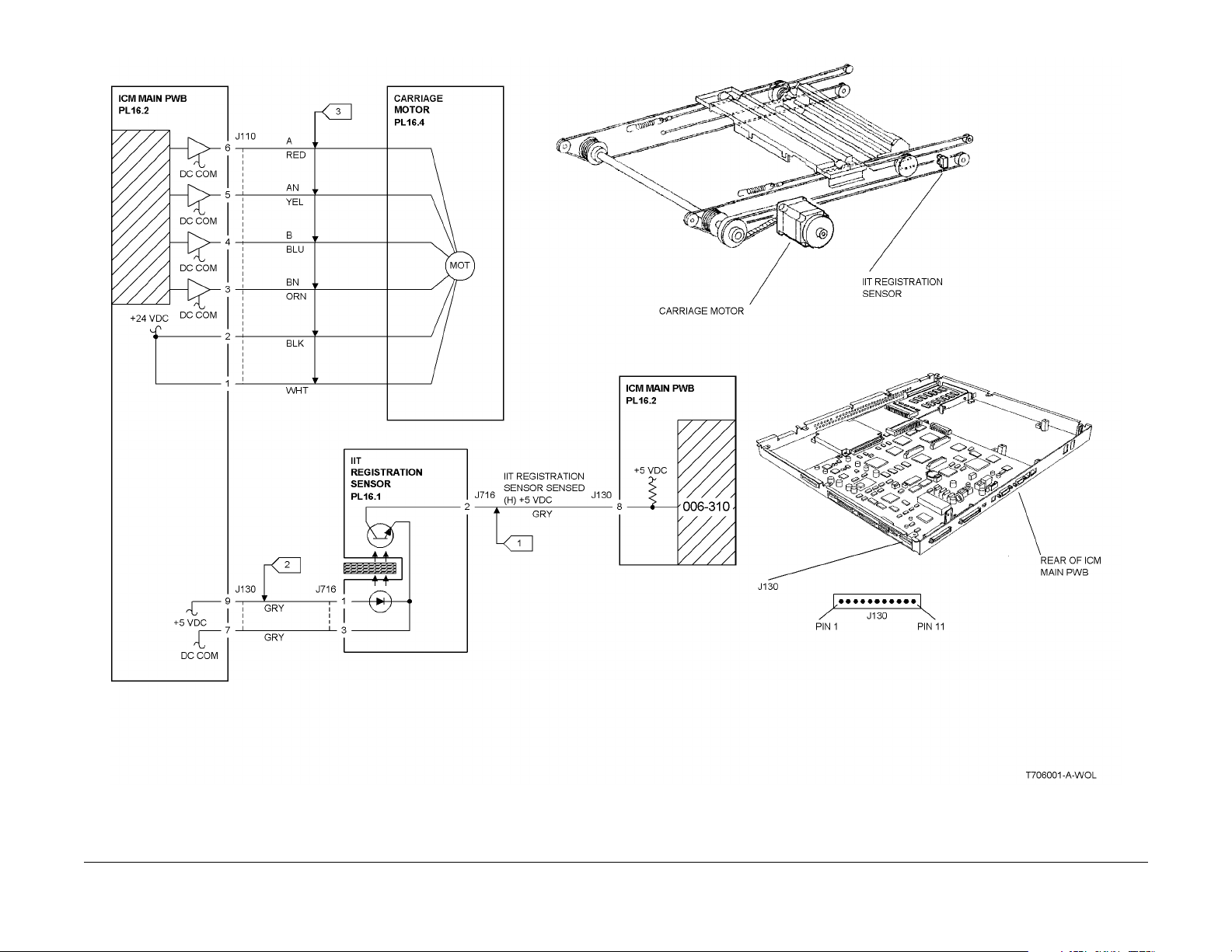
Figure 1 006-310 RAP Cir c uit Diagram
Status Indicator RAPs
006-310
10/00
2-68
Initial Issue
Phaser 790/DocuColor 2006
Page 83

006-311 Exposure Lamp RAP
The CCD does not detect any light from the Lamp.
Initial Actions
Ensure that Mir rors 1, 2, and 3 (PL 16.5) are in place and not damaged or blocked wit h debris.
Procedure
Access IIT Diagnostics from the IIT control panel. Enter code [330-001] and enter a value of 1
for parameter 1. Press the Start button. The Lamp lig hts norma lly.
YN
Inspe c t the Ri bbon Cable between the ICM Main and the FLPS PWB (PL 16.5). The
connections are good and the cable is not damaged.
YN
Re-seat the connectors. If the problem persists, replace the Ribbon Cable (PL 16.5).
Ensur e that th e La mp’s connector J535, is seated on the FLPS PWB (PL 16.5, item 17).
The Lamp Connector J535 is seated correctly.
YN
Re-seat the Lamp Connector J535. If the problem persists, replace the FLPS PWB
(PL 16.5).
Inspect connector P/J 140 on the FPC CCD. The connector appears securely con-
nected and undamaged.
YN
Re-seat the co nnector. If the problem persists, replace the FPC Cable (P L 16.3).
Perform the following:
• Replac e the Lamp (PL 16.5).
• Replac e the ICM Ma in PWB (PL 16.2).
• Replace the FLPS PWB (PL 16.2).
• Replace the Sca nner (PL TBD).
The problem ma y be in t e rmittent. Check all c ab le and P/J connecti ons betw ee n the ICM Ma i n
PWB and the other components in the circuit (Lamp, FLPS PWB, and CCD). Look for loose or
damaged connectors or damaged wiring. Repair as required. If all connections and wiring
appear in good condition, undamaged, and securely connected,
perform the following:
• Replac e the Lamp (PL 16.5).
• Replac e the ICM Ma in PWB (PL 16.2).
• Replace the FLPS PWB (PL 16.2).
• Replace the Sca nner.
Initial Issue
Phaser 790/DocuColor 2006
10/00
2-69
Status Indicator RAPs
006-311
Page 84

006-312 FPC CCD RAP
The FPC CCD does not provide the correct output when originals are scanned.
Procedure
NOTE: The CCD is not field replaceable.
If this Fault Code occurs, replace the following parts in the order shown:
1. The FPC Cable (PL 16.3).
2. The ICM Main PWB (PL 16.2).
3. The Scanner.
Status Indicator RAPs
006-312
10/00
2-70
Initial Issue
Phaser 790/DocuColor 2006
Page 85

006-313 IIT Cooling Fans RAP
The Front or Rear Cooling Fan (or both Fans) failed to operate correctly. A Fan Fail error has
been declared.
Procedure
Remove the Right Cover REP 6.2. Access the IIT Self Diagnostics from the IIT control panel.
Enter code [330-001], and enter a value of 4 for parameter 1. Press the S tart but ton. The
Rear Fan operate s norm a lly.
YN
Disconnect connector J 151 from the ICM Main PWB. +24 VDC is measured between
J151 pin 1 (+) and pin 3 (-) on the ICM Main PWB,
YN
Replace the ICM Main PWB (PL 16.2).
Replace the Rear Fan (PL 16.1).
The Front Fan operates normally.
YN
Disconnect connector J 150 (Blue) on the ICM Main PWB. +24 VDC is measured
between J150 pin 1 (+) and pin 3 (-) on the ICM Main PWB,
YN
Replace the ICM Main PWB (PL 16.2).
NOTE: Remove the Platen Cover for easier access to intermediate connector J 150A/B.
Reconnect connector J 150 on the ICM Main PWB. Disconnect connector J150A. +24
VDC is measured between J150A pin 1 (+) and pin 3 (-).
YN
Go to Flag 1. Check for an open c ircuit or a short circuit to ground. Repair or replace
the wiring as required.
Replace the Front Fan (PL 16.1).
If both Fans operate normally, but the Fault Code persists, go to Flag 2. +5 VDC is mea-
sured between J 151-2 and GND.
YN
Go to Flag 3. +5 VDC is measured between J 150-2 (Grey wire ) and GND.
YN
The problem m a y be intermit te nt . G o to Figure 1. C h ec k fo r l oo se or dama ged connections or damaged wires. If the wiring is OK, replace the Fans (PL 16.1) one at a
time. If the problem persists, replace the ICM Main PWB (PL 16.2).
Replace the Front Fan (PL 16.1). If the problem persists, replace the ICM Main PWB (PL
16.2).
Replace the R ear Fan (PL 16.1). I f the problem persists, re place the ICM Main PW B (PL 16.2).
Initial Issue
Phaser 790/DocuColor 2006
10/00
2-71
Status Indicator RAPs
006-313
Page 86

Figure 1 006-313 RAP Cir c uit Diagram
Status Indicator RAPs
006-313
10/00
2-72
Initial Issue
Phaser 790/DocuColor 2006
Page 87

006-372 Start of Scan Error RAP
During or after warm-up, the Start of Scan (SOS) signal is longer than specif ied.
Procedure
Switch off the power. Remove the IOT Top Cover Assembly (REP 14.4). Remove the Controller Chassis (REP 1.11). Switch on the power. Cheat the Top Cover Interlock. Approxi-
mately +4 VDC is measured between J 14-11 and J14-10 on the MCU PWB.
YN
Go to Fla g 1 an d che ck th e wire for a shor t ci rcu it to gr ou nd. If the w ire is good , re plac e
the MCU PWB (PL 11.2).
+24 VDC is measured between J 14-13 and J14-10 on the MCU PWB.
YN
Replace the MCU PWB (PL 11.2).
Switch off th e pow er. Remo ve t he R OS Co ve r. Disco nnec t J 123 fr om th e ROS . Me asu re th e
resistance between the follow ing plug/jack pins:
• P/J 14-11 on the MCU PWB to J12 3-3
• P/J14-13 on the MCU PWB to J123-1
• P/J14-12 on the MCU PWB to J123-2
• P/J14-10 on the MCU PWB to J123-4
All the measurements are less than 1.0 O hm.
YN
Go to Flag 1 and Flag 2. Check the wires for an open circuit.
Reconnect J 123. Switch on the power. +5 VDC is measured at J 125-1 on the ROS.
YN
Go to the 001-7 05 ROS +5 VDC S witched Voltage RAP.
Switch off the power. Disconnect J 121 from the ROS. Measure the resistance between the following plug/jack pins:
• J 14-5 on the MCU PWB to J121-3
• J14- 4 on the MCU PWB to J121-4
• J14-7 on the MCU PWB to J121-1
All measurements are less than 1.0 Ohm.
YN
Go to Flag 3 and check the wires for an open or short circ uit.
Replace the ROS (PL 5.1). If the problem continues, repl ace the MCU PWB (PL 11.2).
Initial Issue
Phaser 790/DocuColor 2006
10/00
2-73
Status Indicator RAPs
006-372
Page 88

Figure 1 006-372 RAP Cir c uit Diagram
Status Indicator RAPs
006-372
10/00
2-74
Initial Issue
Phaser 790/DocuColor 2006
Page 89

006-701 Angle Sensor RAP
The Angle Sensor circuit has failed to operate correctly.
Initial Actions
Procedure
Remove the Rear Cover REP 6 .4. Disconnect connector J 130 from the ICM Main PWB. +5
VDC is measured between J130 pin 2 and pin 1 on the ICM Main PWB.
YN
Replace the ICM Main PWB (PL 16.2).
Reconnect connector J 130 to the ICM Main PWB. +5 VDC is measured between J130 pin
2 and pin 1.
YN
Go to Flag 2. Check for a short circuit to ground. If the wiring is OK, replace the Angle
Sensor ( PL 16 .1).
Actuate the Angle Sensor. The measured voltage drops to approximately +1.2 VDC or
less.
YN
Go to Flag 1. Check for an open circuit or a short circuit to ground. If the wiring is OK,
replace the angl e se nsor (P L 16 .1) . If th e p roble m p ersis ts , repl ace th e repl ace th e ICM
Main PWB (PL 16.2).
The problem m ay be i ntermittent. Go to F i gu re 1. Che ck fo r loose or damaged co nn ections or
damaged wires. If the wiring is OK, replace the Angle Sensor (PL 16.1). Of the problem persists, replace the ICM Main PWB (P L 16.2).
Initial Issue
Phaser 790/DocuColor 2006
10/00
2-75
Status Indicator RAPs
006-701
Page 90

Figure 1 006-701 RAP Cir c uit Diagram
Status Indicator RAPs
006-701
10/00
2-76
Initial Issue
Phaser 790/DocuColor 2006
Page 91

006-702 Platen Switch RAP
The Plat en Swi tc h ci rcu it has failed t o op erate corre ct ly.
Initial Actions
Visually ch eck to ens ure that the magnet that actuates the Platen Switch is securely in place.
Procedure
Remove the Rear Cover REP 6.4. Disconnect connecto r P/J 719. +5 VDC is measured
between P/J 719 pin 1 GND (DC Common).
YN
Go to Flag 1. Check for an open circuit or a short circuit to ground. If the wiring is OK,
replace the IC M Main PWB (PL 16.2).
Continuity is measured betw een J 719 pins 1 and 2 with the Platen Open.
YN
Replace the Platen Switch (PL 16.1).
An open circuit is measured between J 719 pins 1 and 2 with the Platen Closed.
YN
Replace the Platen Switch (PL 16.1).
Go to Flag 2. Continuity is measur ed between J 719 pin 2 and J130 pin 10 on the ICM
Main PWB.
YN
Repair or replace the wiring as required. If the proble m persists, replace the Platen Switch
(PL 16.1). If the problem still persists, replace the ICM Main PWB (PL 16.2).
The problem m ay be i ntermittent. Go to F i gu re 1. Che ck fo r loose or damaged co nn ections or
damaged wires. If the wiring is OK, replace the Angle Sensor (PL 16.1). Of the problem persists, replace the ICM Main PWB (P L 16.2).
Initial Issue
Phaser 790/DocuColor 2006
10/00
2-77
Status Indicator RAPs
006-702
Page 92

Figure 1 006-702 RAP Cir c uit Diagram
Status Indicator RAPs
006-702
10/00
2-78
Initial Issue
Phaser 790/DocuColor 2006
Page 93

006-703 Scanner Error RAP
Procedure
Switch the power off, then on. If the fault remains, replace the IPS PWB (PL 16.2). If this does
not resolve the problem, replace the ICM Main PWB (PL 16.2).
006-704 System Error (093-XXX) RAP
Procedure
Ensure that the correct levels of firmware are installed for all components of the system.
Reload if required (GP 8, GP 9, and GP 10). If reloading firmware does not resolve the problem, replace the ICM Mai n PWB (PL 16.2 ).
Initial Issue
Phaser 790/DocuColor 2006
10/00
2-79
Status Indicator RAPs
006-703, 006-704
Page 94

006-906/907/908/909 RAP
006-906: Contr ol Logic detected an AOC1 error at job start or initialization.
006-907: Control Logic detected an AGC error.
006-908: Control Logic detected an OE Pixel Judgement err or.
006-909: Contr ol Logic detected an Auto Gradat ion correction error.
Procedure
Check t he wiri ng an d co nn ecti ons to t he II T La mp ( PL 1 6.5 ). I f the wire s ar e O K, repla ce t he
Lamp. If the fault remains, replace the ICM Main PWB (PL 16.2).
Status Indicator RAPs
006-906/907/908/909
10/00
2-80
Initial Issue
Phaser 790/DocuColor 2006
Page 95

007-324 Environment Sensor RAP
The control logic has detected an open circuit in the Environment Sensor.
Initial Actions
• Ensure that the E nvironment Sensor is free of dust and dirt.
Procedure
Switch off the power. Disconnect the power cord. Go to REP 1.8, and remove the Duplex Tray
Assembly from the copier/printer. Check that the P/J 105 connector on the Environment Sensor board is properly connected. The P/J 105 connector is good.
YN
Connect the P/J 105 connector. Connect the power cord and switch on the power.
Go to REP 1.11, and remove the Controller Chassis to gain access to the MCU PWB connectors. Go to Flag 1. Check the wires for an open or a short circuit to ground. The wires are
good.
YN
Repair the wires. Connect the power cord and switch on the power.
Replace the Environment Sensor (PL 11.2). Connect the power cord and switch on the power.
If the problem continues, re place the MCU PWB (PL 11.2).
Initial Issue
Phaser 790/DocuColor 2006
10/00
2-81
Status Indicator RAPs
007-324
Page 96

Figure 1 007-324 RAP Cir c uit Diagram
Status Indicator RAPs
007-324
10/00
2-82
Initial Issue
Phaser 790/DocuColor 2006
Page 97

007-340 Feeder Motor Fail RAP
The control logic has detected the signal, Feeder Motor Fail (H) +5 VDC.
Procedure
Enter [DO-B8]. The Feeder Motor is operating.
YN
There is +24 VDC from J 21 3 pin 1 on the Feeder PWB to printer frame.
YN
Go to Flag 1 . Ch eck th e wir es for an o pen or a shor t cir cuit to grou nd. R epair t he
wires.
Enter [DO-B8]. There is 0 VD C from J 217 pin 12 to printer fram e.
YN
Replace the Feeder PWB (PL 13.4).
Replace the Feeder Motor (PL 13.4). If the problem continues, replace the Feeder PWB
(PL 13.4).
There is 0 VDC from J 239 pin 4 to printer frame.
YN
Go to Flag 2. Check the wire for an open c ircuit. If th e wi re is bad, re pair it. If the w ire is
good, replace the Feeder Motor (PL 13.4), (REP 8. 20).
Replace the Feeder PWB (PL 13.4).
Initial Issue
Phaser 790/DocuColor 2006
10/00
2-83
Status Indicator RAPs
007-340
Page 98

Figure 1 007-340 RAP Cir c uit Diagram
Status Indicator RAPs
007-340
10/00
2-84
Initial Issue
Phaser 790/DocuColor 2006
Page 99

007-341 Inverter Motor Fail RAP
The Cont rol Logic has detected an Inverter Motor Fail (H) +5 VDC signal.
Initial Actions
Ensure that th e Upper and the Lower Inverter Assemblies are properly cl osed.
Procedure
Enter diagnostic code [DO-A0]. The Inverter Motor operates.
YN
There is +24 VDC from J 139 pin 9 to printer frame.
YN
There is +24 VDC from J 14 2 Pin 16 to pr inter frame.
YN
Go the Flag 2. Check the wires for an open or short circuit to ground. If the
wires are good , replace the MCU P WB (PL 11.2).
Go to Flag 1. Check the wires for an open or a short circuit to ground. If the wires are
good, replace the Duplex Controller PWB (PL 15.6). If the problem continues,
replace the Inverter Motor (PL 15.6).
There is 0 VDC from J 139 pin 7 to printer frame.
YN
Replace the Duplex Co ntroller PWB (PL 15.6).
Go to Flag 1. Check the wir es for and open circuit. The wires are good.
YN
Repair the wires.
Replace the Inverter Motor (PL 15.5).
There is 0 VDC from Inverter Motor J 147 pin 4 to the printer frame.
YN
Replace the Duplex Co ntroller PWB (PL 15.6).
Check th e Drive Me chanism , gears an d pulleys for missin g teeth an d proper fu nction. If the
gears are good, Replace the Inverter Motor (PL 15.5).
Initial Issue
Phaser 790/DocuColor 2006
10/00
2-85
Status Indicator RAPs
007-341
Page 100

Figure 1 007-341 RAP Cir c uit Diagram
Status Indicator RAPs
007-341
10/00
2-86
Initial Issue
Phaser 790/DocuColor 2006
 Loading...