

Page 1
Xantrex
XC3012, XC5012,
XC1524 and XC2524
Owner’s Guide
12 V / 30 A
12 V / 50 A
Battery Charger
24 V / 15 A
24 V / 25 A
Page 2

Page 3

Xantrex XC3012, XC5012,
XC1524 and XC2524
Battery Charger
Owner’s Guide
Page 4

About Xantrex
Xantrex Technology Inc. is a world-leading supplier of advanced power electronics and controls with
products from 50 watt mobile units to one MW util ity-s cale system s for wind, sol ar , ba tteri es, fuel cel ls,
microturbin es, and backup powe r appl icat ions in bot h grid- connec ted and sta nd-alone systems . Xantrex
products inc lude inverters, battery charge rs, programmable power supplies, and variable speed drives
that convert, su pply, control, clea n, and distribute el ectrical power.
T rademarks
Xantrex XC3012, XC5012, XC1524 and XC2524 Battery Charger is a trademark of Xantrex
Intern ational. Xantrex is a registered trademark of Xantrex International.
Other trademar ks, registered trademarks, and product names are the property of their respective owners
and are us ed herein for identification purposes only.
Notice of Copyright
Xantrex XC3012, XC5012, XC1524 and XC2524 Battery Charger Owner’s Guide© August 2005
Xantrex International. All rights reserved.
Disclaimer
UNLESS SPECIFICALLY AGREED TO IN WRITING, XANTREX TECHNOLOGY INC.
(“XANTREX”)
(a) MAKES NO WARRANTY AS TO THE ACCURACY, SUFFICIENCY OR SUITABILITY OF
ANY TECHNICAL OR OTHER INFORMATION PROVIDED IN ITS MANUALS OR OTHER
DOCUMENTATION.
(b) ASSUMES NO RESPONSIBILITY OR LIABILITY FOR LOSS OR DAMAGE, WHETHER
DIRECT, INDIRECT, CONSEQUENTIAL OR INCIDENT AL, WHICH MIGHT ARISE OUT OF
THE USE OF SUCH INFORMATION. THE USE OF ANY SUCH INFORMATION WILL BE
ENTIRELY AT THE USER’S RISK.
Date and Revision
August 2005 Revision B
Part Number
975-0187-01-01
Contact Inform a tion
Phone: 1 800 670 0707 (toll free North America)
+34 93 470 5330 (Europe)
1 360 925 5097 (direct and rest of world)
Fax: 1-800 994 7828 (toll free North America)
Email: customerservice@xantre x.com (North America)
Web: www.xantrex.com
+34 93 473 6093 (Europe)
1 360 925 5143 (direct and rest of world)
support.euro pe@xantrex.com (Europe)
customerservice@xantrex.com (rest of world)
Page 5

About This Guide
Purpose
The purpose of this Owner’s Guide is to provide explanations and procedures for
installing, operating, maintaining, and troubleshooting the Xantrex XC3012,
XC5012, XC1524 and XC2524 Battery Charger.
Scope
The Guide provide s safety guidelines, detailed planning and setup information,
procedures for insta lling the charger, as well as information about operating and
troubleshooti ng the unit. It does not provide details about particular brands of
batteries. Consult individual battery m anufacturers for this information.
Audience
The Guide is intended for anyone who ne eds to install and operate the Xantrex
XC3012, XC5012, XC1524 and XC2524 Battery Charger . Installers should be
certified tech ni ci ans or electri ci a ns.
Organization
This Guide is organized into 4 chapters and 1 appendix:
Chapter 1, “Introduction”: Chapter 1 describes the XC Se ries standard features. It
also provides information to prepare for instal lation of the XC Series.
Chapter 2, “Installation”: Chapter 2 pr ovides procedures for installing, testing and
configuring the XC Series.
Chapter 3, “Operation”: Chapter 3 describes the operating states and provides
procedures for char ging a battery and performing an equalization.
Chapter 4, “Troubleshooting”: Chapter 4 contains information on error codes and
procedures for troubl eshooting your XC Series char ger.
Appendix A, “Spe cifications”: Appendix A details the specifications for the
XC Series.
iii
Page 6
About This Guide
Conv en t io n s Used
The following conventions are used in this guide.
WARNING
Warnings identify conditi ons or practices that could result in personal inj ury or loss of life
CAUTION
Cautions ide ntify conditions or practices that could result in dama ge to the unit or other
equipment.
Important:
serious as a caution or warning.
This Guide contains information for fou r versions of the XC Series.
The Xantrex XC3012 Battery Charger (12 V, 30 A) will be referred to as the
XC3012 when it is being referenced individually.
The Xantrex XC5012 Battery Charger (12 V, 50 A) will be referred to as the
XC5012 when it is being referenced individually.
The Xantrex XC1524 Battery Charger (24 V, 15 A) will be referred to as the
XC1524 when it is being referenced individually.
The Xantrex XC2524 Battery Charger (24 V, 25 A) will be referred to as the
XC2524 when it is being referenced individually.
When the Xantrex XC3012, XC5012, XC1524 and XC2524 Battery Chargers are
being refere nced tog eth er, they will be refer red to as the X C Series.
These notes describe things which are important for you to know, but not as
Relat ed Inf o rmation
You can find more information about Xantrex Technology Inc. as well as its
products and services at www.xantrex.com
iv 975-0187-01-01
Page 7

Important Safety Instructions
WARNING
This chapte r contains important safety and operating instructions as prescribed by safety
standards for chargers used in RV and marine application s. Read and keep this Owner’s
Guide for future reference.
1. Before installi ng or using the Xantrex XC3012, XC5012, XC1524 or XC2524
Battery Charge r (XC Series ), read all instructions and cautionary markings on
the XC Series, the batteries , and all appropriate sections of this guide.
2. Do not expose t he XC Series to rain , snow, spray, or bilge water. T o reduce risk
of fire hazard, do not cover or obstruct the ventilation openings. Do not install
the XC Seri es in a zero -c le ara n ce co mpartment. Over he at ing may result.
3. Use only attachments recommend ed or sold by Xantre x. Doing otherwise may
result in a risk of fire, elect ric shock, or injury to persons.
4. The XC Series is designe d to be permanently connected to the AC and DC
electrical sys tems. Xantrex recommends that all wiring be done by a certif ied
technician or electrician to ensure compliance with the local and national
electrical codes relevant to your installation. It is the responsibility of the
installer to ensure that the installation of the XC Series complie s with all
relevant elect rical codes.
5. T o avoid a risk of fire and electric shock, make sure that existing wiring is in
good condition and that wire is not undersized. Do not operate the XC Series
with damaged or substandard wiring.
6. Do not disassemble the XC Series. It contains no user-servi ceable parts.
Attempti ng to serv i ce th e XC Series your se lf may resu lt in a risk of elec t rical
shock or fire.
NOTE: Disassembling the XC Series will void your warrant y.
7. T o reduce the risk of electrical shock, disconnect both AC and DC power from
the XC Series before attempting any maintenance or cleaning or before
working on any circuits connected to the XC Series. Turning the XC Series off
using the remote display will not reduce this risk.
v
Page 8
Safety
8. The XC Series is provide d with an AC ground conductor that must be
connected to the AC input ground and a DC ground stud which must be
connected to the DC system ground.
9. For marine applications in the United States, external connections to the
charger shall comply with the United States Coast Guard Electrical Regulations
(33CFR183, Sub pa rt 1).
Explo sive Gas and Battery Precauti on s
WARNING: Explosion or fire hazard
1. Read this guide and follow the instructions exactly before installing or using
your XC Series.
2. Follow all instructi ons published by the battery manufacturer and the
manufacturer of the equipment in which the battery is installed.
3. Working in the vicinity of lead-acid batteries is dang erous. Batteries generate
explosive gases during nor mal operation.
4. The XC Series has been approved as Ignition Protected. It may be installed in
areas containing gasoline tanks and fittings which require Ignition Protected
equipment. Xantrex recommends, nevertheless, that it is safest not to install
electrical equip me n t in thes e area s.
5. Make sure the area around the battery is well ventilated.
6. Never smoke or allow a spark or flame near the engine or batteries.
7. Use caution to reduce the risk of dropping a metal tool on the battery. It could
spark or short circuit the battery or other electrica l parts a nd could cause an
explosion.
8. Remove all metal items, like rings, bracelets, and watches when working with
lead-acid batteries. Lead-acid batteries produce a short circuit current high
enough to weld metal, causing a severe skin burn.
9. Have someone within range of your voice or clos e enough to come to your aid
when you work near a lead-acid battery.
vi 975-0187-01-01
Page 9

10. Have plenty of fresh water and soap nearby in case bat tery acid contacts skin,
clothing, or eyes.
11. Wear complete eye protection and clothing protection. Avoid touching your
eyes while wo rki ng near batteries.
12. If battery acid conta cts sk in or cl othin g, wash immediate ly wit h soap and wat er.
If acid enters your eye, immed iately fl ood it with running cold water for at least
twenty minutes a nd get medical attention immediately.
13. If you need to remove a battery, always remove the ground terminal from the
battery first. Make sure al l accessories are off to reduce the possibility of
causing a spark.
FCC Information
This equipment has been tested and found to comply with the limits for a C lass B
digital device, pursuant to part 15 of the FCC Rules. These lim its are designed to
provide reasonabl e protection against harmful interference in a residential
installati on. This eq uipment gener ates , uses, and can radiat e radio fr equency e nergy
and, if not installed and used in accordance with the instructions, may ca use
harmful interfere nce to radio communications.
However, there is no guarantee that inter ference will not occur in a particula r
installati on. I f this equipment does cause harmful interference to radio or television
reception, which can be determine d by turning the equipment of f and on, the user is
encouraged to try to correct the interference by one or more of the following
measures:
Safety
• Reorient or relocate the receiving antenna.
• Increase the separation between the equipment and receiver.
• Connect the equipment into an outlet on a circuit differ ent from that to which
the receiver is connect ed.
• Consult the dealer or an experienced radio/TV technici an for help.
975-0187-01-01 vii
Page 10

viii
Page 11

Contents
Important Safety In str uctions
Explosive Gas and Battery Precautions - - - - - - - - - - - - - - - - - - - - - - - - - - - - - - - - vi
FCC Information - - - - - - - - - - - - - - - - - - - - - - - - - - - - - - - - - - - - - - - - - - - - - - -vii
1
Introduction
Xantrex XC3012, XC5012, XC1524 and XC2524 Battery Charger Features - - - - - - 1–2
XC Series Appearance- - - - - - - - - - - - - - - - - - - - - - - - - - - - - - - - - - - - - - - - - - - 1–3
Information Centers of the XC Series- - - - - - - - - - - - - - - - - - - - - - - - - - - - - - - - - 1–4
Remote Display - - - - - - - - - - - - - - - - - - - - - - - - - - - - - - - - - - - - - - - - - - - - 1–4
Onboard Status Panel - - - - - - - - - - - - - - - - - - - - - - - - - - - - - - - - - - - - - - - - 1–6
Rear Panel- - - - - - - - - - - - - - - - - - - - - - - - - - - - - - - - - - - - - - - - - - - - - - - - - - - 1–7
Preparing for Installation - - - - - - - - - - - - - - - - - - - - - - - - - - - - - - - - - - - - - - - - - 1–8
Tools and Materials - - - - - - - - - - - - - - - - - - - - - - - - - - - - - - - - - - - - - - - - - 1–9
Location - - - - - - - - - - - - - - - - - - - - - - - - - - - - - - - - - - - - - - - - - - - - - - - - 1–10
Wiring Requirements - - - - - - - - - - - - - - - - - - - - - - - - - - - - - - - - - - - - - - - 1–12
DC Wiring - - - - - - - - - - - - - - - - - - - - - - - - - - - - - - - - - - - - - - - - - - - - 1–12
AC Wiring - - - - - - - - - - - - - - - - - - - - - - - - - - - - - - - - - - - - - - - - - - - - 1–13
Battery Bank Size Requirements - - - - - - - - - - - - - - - - - - - - - - - - - - - - - - - - 1–14
2
Installation
Installing the XC Series - - - - - - - - - - - - - - - - - - - - - - - - - - - - - - - - - - - - - - - - - - 2–2
Installation Sequence - - - - - - - - - - - - - - - - - - - - - - - - - - - - - - - - - - - - - - - - 2–2
Pre-Installing DC Wiring - - - - - - - - - - - - - - - - - - - - - - - - - - - - - - - - - - - - - - 2–3
Pre-Installing AC Wiring - - - - - - - - - - - - - - - - - - - - - - - - - - - - - - - - - - - - - - 2–4
Mounting the Remote Display - - - - - - - - - - - - - - - - - - - - - - - - - - - - - - - - - - 2–7
Mounting - - - - - - - - - - - - - - - - - - - - - - - - - - - - - - - - - - - - - - - - - - - - - - - - 2–8
Grounding - - - - - - - - - - - - - - - - - - - - - - - - - - - - - - - - - - - - - - - - - - - - - - - - 2–9
Final Connections - - - - - - - - - - - - - - - - - - - - - - - - - - - - - - - - - - - - - - - - - 2–10
Final DC Connections - - - - - - - - - - - - - - - - - - - - - - - - - - - - - - - - - - - - 2–11
Final AC Connections - - - - - - - - - - - - - - - - - - - - - - - - - - - - - - - - - - - - 2–12
Powering Up - - - - - - - - - - - - - - - - - - - - - - - - - - - - - - - - - - - - - - - - - - - - - 2–12
975-0187-01-01 ix
Page 12

Contents
Installing Optio nal Accessories- - - - - - - - - - - - - - - - - - - - - - - - - - - - - - - - - - - - 2–13
Battery Temperature Sensor - - - - - - - - - - - - - - - - - - - - - - - - - - - - - - - - - - 2–13
Drip Protection Rubber Boots - - - - - - - - - - - - - - - - - - - - - - - - - - - - - - - - - 2–14
Configuring the XC Series- - - - - - - - - - - - - - - - - - - - - - - - - - - - - - - - - - - - - - - 2–15
3
Operation
About Charging - - - - - - - - - - - - - - - - - - - - - - - - - - - - - - - - - - - - - - - - - - - - - - - 3–2
Multiplex 3-Stage Charging - - - - - - - - - - - - - - - - - - - - - - - - - - - - - - - - - - - - 3–2
Sequential 2-Stage Charging - - - - - - - - - - - - - - - - - - - - - - - - - - - - - - - - - - - 3–3
Charging Overview - - - - - - - - - - - - - - - - - - - - - - - - - - - - - - - - - - - - - - - - - 3–3
Charging Batteries - - - - - - - - - - - - - - - - - - - - - - - - - - - - - - - - - - - - - - - - - - - - - 3–6
Equalizing Flooded Batteries - - - - - - - - - - - - - - - - - - - - - - - - - - - - - - - - - - - - - - 3–8
Transitioning the XC Series to On, Disabled or Off - - - - - - - - - - - - - - - - - - - - - - 3–10
Accessing Charger Inform ation - - - - - - - - - - - - - - - - - - - - - - - - - - - - - - - - - - - 3–11
Reading Remote Display and Onboard Status Indicator Lights - - - - - - - - - - - 3–11
Reporting While Charging or Equaliz ing - - - - - - - - - - - - - - - - - - - - - - - - - - 3–13
Reporting While Battery Monitoring - - - - - - - - - - - - - - - - - - - - - - - - - - - - - 3–14
Reporting While Disable d - - - - - - - - - - - - - - - - - - - - - - - - - - - - - - - - - - - - 3–14
Using A Generator As Source Power - - - - - - - - - - - - - - - - - - - - - - - - - - - - 3–15
4
Troubleshooting
Care and Maintenance- - - - - - - - - - - - - - - - - - - - - - - - - - - - - - - - - - - - - - - - - - - 4–2
Indicator Light Flashing Sequences- - - - - - - - - - - - - - - - - - - - - - - - - - - - - - - - - - 4–3
Error Messages on Remote Display- - - - - - - - - - - - - - - - - - - - - - - - - - - - - - - - - - 4–4
Problem Solving - - - - - - - - - - - - - - - - - - - - - - - - - - - - - - - - - - - - - - - - - - - - - - 4–7
A
Specifications
Physical Specifications - - - - - - - - - - - - - - - - - - - - - - - - - - - - - - - - - - - - - - - - - -A–2
Electrical Specifications - - - - - - - - - - - - - - - - - - - - - - - - - - - - - - - - - - - - - - - - -A–2
AC Input Specification s - - - - - - - - - - - - - - - - - - - - - - - - - - - - - - - - - - - - - - - - -A–3
Temperature Specifications - - - - - - - - - - - - - - - - - - - - - - - - - - - - - - - - - - - - - - -A–4
Protection Features - - - - - - - - - - - - - - - - - - - - - - - - - - - - - - - - - - - - - - - - - - - - -A–4
Approvals - - - - - - - - - - - - - - - - - - - - - - - - - - - - - - - - - - - - - - - - - - - - - - - - - - -A–5
Warranty and Product Information
x 975-0187-01-01
- - - - - - - - - - - - - - - - - - - - - - - - - - WA–1
Page 13

1
Introduction
Chapter 1 describes the XC Series standard features. It
also provides information to prepare for installation of
the XC S er ies.
Page 14

Introduction
Xantrex XC3012, XC5012, XC1524 and XC2524 Battery
Charger Feat u res
The XC Series provides the following standard features:
• three full current rated, independently controlled outputs which enable it to
charge thre e diff erent batte rie s or battery banks . Each bank can be of a dif ferent
battery type, stage of charging, and temperature compensation
• one battery tempera ture sensor (BTS) is included. Optional BTSs may be
purchased for the other two outputs, to provide complete optimal battery
charging to each battery or bank
• battery monitor ing functions while in float mode or rest mode
• correct char ging voltage for your batterie s when connecte d to almost any sing le
phase AC power outlet in the world
• invertable rem ote display panel which can also be removed from the charger
and mounted up to 20 m (65 ft) away for remote control and monitoring
The XC Series provides the following protection features:
• true “fuseless” reve rse polarity protection to guard against continuous r everse
battery polarity without charger damage
• AC over voltage protection shutdown
• over temperature protection shutdown
• electronic current limiting for protec tion against short circuit on the unit’s
output
• built-in prote ction against accidental connection to a higher battery voltage , up
to 24 VDC
• battery temper ature compensation to 0 °C (32 °F) (with BTS installed)
• ignition prot ected rating, enabling installation in engine spaces
• isolated design to reduce shock hazard
• automatic char ge resumption after AC power interr uption
1–2 975-0187-01-01
Page 15
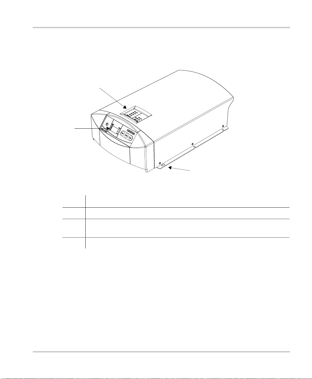
XC Series Appearance
This section describes the parts of the XC S eries. Figure 1-2 shows the XC Series.
2
1
XC Series Appearance
3
Figure 1-1
Item Description
1 Remote display for all programming functions and monitoring of the XC Series.
2 Onboard status panel for monitoring charger status and charging current a t the
3 Mounting flanges
975-0187-01-01 1–3
XC Series
XC Series when the remote display is mounted remotely from the charger.
Page 16
Introduction
Inform ation Centers of the XC Series
Remote Display
This section describe s the parts of the remote display of the XC Series. The remote
display can be rotated 180°, or it can be r emoved and remotely mounted up to 20 m
(65 ft) from the XC Series for convenience. Figure 1-2 shows the remote display.
A “press and h old” action on the remote display means that the button must be held
down for more than 2 seconds in order to send the instruction. A “press” action on
the remote display means that the button must be pressed and re leased before 2
seconds have elapsed.
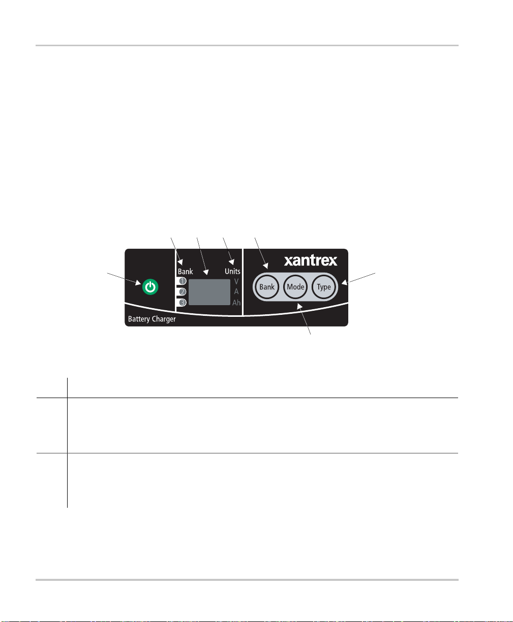
2 3 4 5
1
7
Figure 1-2
Item Description
1
ON/STANDBY push button
• Press to turn on or disabl e the charger while AC powe r is conne cted
• Press and hold to apply selection when in setup or equalization mod e
• Press to show battery bank voltages when AC is disconnected
2 Battery bank indicator lights
• Illuminate to sh ow which bank has been selected for setup or status dis play
• Illuminate during a fault or warning to show which bank ha s the fault or warning, or
illuminate all three if the charger itself has the f ault or warning
XC Series Remote Display
6
1–4 975-0187-01-01
Page 17

Information Centers of the XC S eries
Item Description
3 Alpha-numeric dis play shows
• Configuration
• Fault or warning message s (see T able 4-2 on page 4–4)
• Battery bank voltage and c urrent
• Type of charging (2 stage or 3 stage)
• State of charge
4 Units indica tor lights
• Illuminate to sh ow unit of m easure for the numeric read-out on the alpha-numeric display
5
BANK selection pus h button
• Press to select a bank during setup
• Press at the same time as
6
TYPE selection push button
MODE to enter o r ex it equalizatio n mode.
• Press to select flooded (lead acid), gel, AGM, or lead calcium batteries.
7
MODE selection push button
• Pres s to select chargi n g st at e du r i ng s et u p : 2 st ag e o r 3 stag e.
• Press at the same time as
BANK to enter or exit equalization mode.
• Press and hold to enter setup.
The indicator li ghts and dis play are also used to indi cate err or co des. See Chapter 4,
“Troubleshooting” for a list of faults and how to clear them.
975-0187-01-01 1–5
Page 18
Introduction
Onboard Status Panel
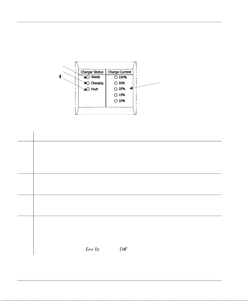
This section describes the parts of the onboard status panel of the XC Series.
Figure 1-3 shows the panel.
2
3
4
1
Figure 1-3
Item Description
1 Charg e Cu rrent
• Displays the output charge current in % of charger maximum for the bank being charged
• 100% indicator ligh t flashes to indicate battery temperature too high (> 50 °C, 122 °F)
• 10% indicator light flashes to indicate battery temperature too low (< 0 °C, 32 °F)
• 25% indicator light flashes to indica te that a battery has been disqualified (see page 3–4)
2
3
4
Charger Status -
• Ready indicator light illuminated indicates all batteries are fully charged, and are now in
float or rest
Charger Status -
• Charging indicator light illuminated indicates unit is performing a normal charge cy cle
• Charging indica tor lig ht flashing indi ca tes that the unit is performing an equa liza tion cycl e
Charger Status -
• Fault indicator light continuously illuminated indicates any fault condition that prevents
the XC Series from charging one or more batteries, but is not a charge r failure - remote
display shows details of fault
• Fault indicator light flashing indicates the XC Series has experienced a charger failure remote display shows
XC Series Onboard Status Panel
READY
CHARGING
FAULT
err
followed by
CHf
1–6 975-0187-01-01
Page 19

Rear Panel
This section desc ribes the part s of the rea r panel of the XC Series. Figure 1-4 shows
the rear panel.
Rear Panel
9
7
11
++
2
Bank3Bank
Figure 1-4
10
XC Series Rear Panel
6
Item Description
1 Remote displa y com munication connector
2 BTS1 (battery temper ature sensor for bank 1) connector
3 BTS2 (battery temper ature sensor for bank 2) connector
4 BTS3 (battery temper ature sensor for bank 3) connector
5 Battery negative, common for all 3 banks (6 mm stud)
8
2
3
4
1
5
6 Battery positive for bank 1 (6 mm stud)
7 Battery positive for bank 2 (6 mm stud)
8 Battery positive for bank 3 (6 mm stud)
9 Fan asse m b l y
10 Chassis ground (earth) for DC wiring
11 AC wiring access panel
975-0187-01-01 1–7
Page 20
Introduction
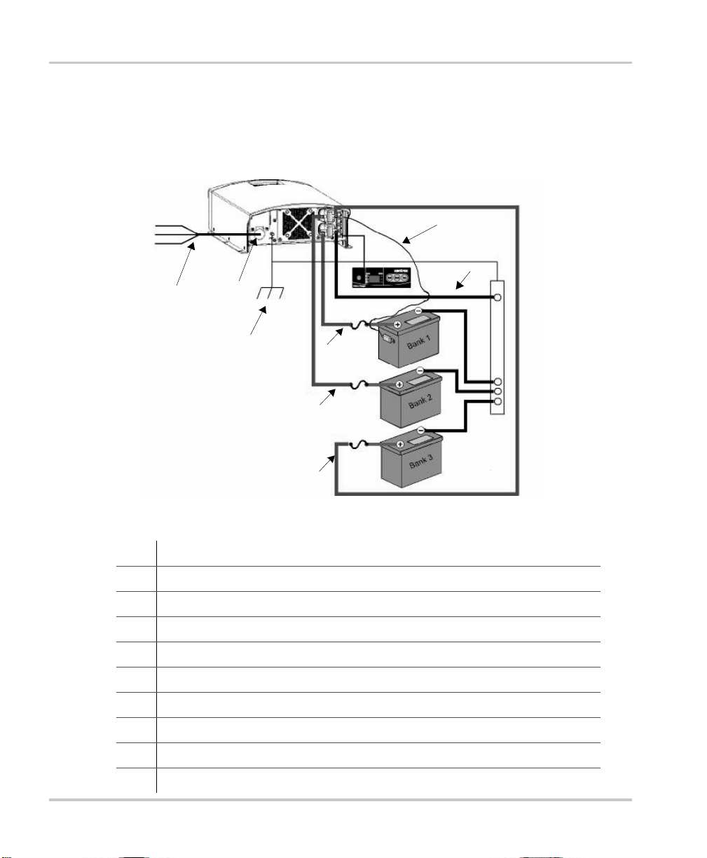
Preparing for Installation
The XC Series is designe d to be permanently mounted. Figure 1-1 shows a typical
installati on with three batteries, a BTS and a remote display. It also shows the AC
and DC wiring and protection device s requir ed for a successful installa tion.
L
N
G
1
Figure 1-5
2
10
XC Series System
8
5
4
5
4
5
4
9
3
7
6
6
6
1 AC mains source with correct s ize and type of circuit breaker
2 AC input wiring compartment
3 DC negative c able
4 DC positive cables
5 DC circuit breaker or DC fuse and disconnect
6 Battery or battery bank
7 Engine ground bus or DC negative bus
8 Remote display panel
9 Battery temper ature sensor (#1 is standard equipment. #2 a nd #3 are optional)
10 DC chassis ground (earth)
1–8 975-0187-01-01
Page 21

Tools and Materials
To mount and connect the XC Series you need the following tools:
• 10 mm wrench or socket for the DC terminals and ground stud
• Phillips screwdriver for securing the AC wiring compartment cover
• power drill
• drill bit for pil ot holes for mounting screws
• wire stripper
• manufacturer's recommended crimp tool for any crimp terminals that are being
used
You need the following mate ri als:
• 3 conductor AC input wiring
Use the inf ormation in “AC Wiring” on page 1–13 and your local electrical
codes to determine the corre ct wire and breaker or fuse.
• AC cable str ain relief (if the one included is not sufficient for your local
electrical code requirements)
• appropriat ely sized D C ca bles fo r each b at tery, with suitable c onnectors at the
battery end
• appropriate ly sized DC chassis ground (earth) with suita ble connectors
• ring terminals to fit 6 mm (1/4 in.) studs at the charger end
• DC fuse and disconnect or circuit breaker for each battery bank
• mounting hardware, 3 m m (#6) corrosion resistant 6 piec es.
• other means to route and secure AC and DC wiring
Preparing for Installation
975-0187-01-01 1–9
Page 22

Introduction
Location
Install the XC Series in a location that meet s the following requirements :
Condition Requirement
Dry The XC Series must be installed in a dry location not subj ec t to rain, spray or splashing
bilge water.
Clean The XC Series should not be exposed to metal filings or any other form of conductive
contamination.
Cool The ambient air temperat ure should be between 0 °C - 50 °C (32 °F - 122 °F) for best
performance.
Ven t il at ed There must be at least 76 mm (3 in.) of clearanc e on each end of the XC Ser i es f or ai r
flow. Ventilation openings on the unit must not be obstructed. If mounting in a tight
fitti ng co m p a r tment, th e co mp artmen t m u st be v e n t il at ed w it h cut - o ut s to pr e vent
overheating.
Safe This battery charger is ignition protected, so it can be installed in areas containing
gasoline tanks or fittings which usually require ignition protected equipment. Xantrex
recommends, however, that it is safest not to install el ectrical equipment in these areas.
Close to
batteries
The XC Series should be installed as close as possible to the batteries, but not in the
same compartment to prev ent excess corrosion. Avoid excessive ca ble lengths and use
the recommended wire sizes. Xantrex recommends <3% wire voltage drop (r ound
circuit) on battery cables under full load.
When planning where and how to mount the XC Series, be sure the installa tion
allows the charge r to be mounted in one of the permitted vertical or horizonta l
orientations.
For marine installat ions, only the mounting configura tions with a check mark in
Figure 1-6 meet the North American and Europea n marine requirements. Marine
products are required to meet drip tests, to ensure safety in the presenc e of
condensation. If you are cert ain your installation is not subject to moisture,
configuration d) in Figure 1- 6 may be used.
1–10 975-0187-01-01
Page 23

a) b)
Preparing for Installation
Vertical
c) d)
Horizontal
Figure 1-6
XC Series Mounting Orientations
Vertical - this c onf igurat ion i s unsaf e and
should not be used
Vertical - thi s configuration may be used
in an environ ment wh ich is dr y and clean
only (non-mari ne)
975-0187-01-01 1–11
Page 24
Introduction
Wiring Requirements
WARNING
Wire and fuse sizes ar e dict ated by electrical standards. D ifferent standards apply in
differe nt countries and different types of installations, for example, boat, home or RV. It is
the resp onsibility of the install er to ensure that the installation comp lies with all applicable
standards.
CAUTION
Ensure that both wires and fuse s are corr ectly sized .
Maximum conti nuous c urrent a vaila bl e from t he cha rger may be an add iti onal 6 –10% abov e
the nominal current rating of the charger. Out put current may also vary depending on
ambient tempe rature conditions.
DC Wiring
The following two tables show some typica l wire sizes, based on 3% voltage drop
(round circuit) , 75 °C (167 °F) rated wire and wiring being inside the engine
compartment – assumed ambient of 50 °C (122 °F).
Table 1-1
DC Wiring Requirements
Wire Length
(
maximum length one way) Wire Size (AWG and mm
2
)
feet meters XC3012 XC5012 XC2524 XC1524
51.5No. 10
2
5mm
7.5 2.25 No. 8
2
8mm
20 6 No. 6
13 mm
No. 6
13 mm
No. 6
13 mm
No. 4
2
19 mm
2
2
2
No. 10
5mm
No. 10
5mm
No. 10
5mm
2
3mm
2
No. 12
No. 12
2
3mm
2
No. 12
2
3mm
2
1–12 975-0187-01-01
Page 25

AC Wiring
Preparing for Installation
Over-current protect ion disco n nect
The DC circuit from the battery to the char ge r must be equipped with a disconnect
and over-cur rent protection device. The device usually consists of a DC-rated
circuit breaker, a “fused disconnect”, or a separate fuse and disconnect. These
devices must be rated for DC voltage and current. Do not substitute devices rate d
only for AC voltage; they may not operate prope rly.
The current rating of the DC fuses must be matched to the size of the DC wiring
used, in accord an ce wi th the appl icab l e cod es.
The DC chassis ground (earth) shoul d not be more than one siz e smaller than the
DC wiring size selected (see Table 1-1). Refer to your local electrical codes for
verification.
The AC wiring must meet the following requir ements before you install the
XC Series:
The AC input wiring for the XC Series should be three-conductor cable, providing a
line, neutral, and ground conductor (or L1, N,
GND) in an outer jacket.
For example, in North America for 120 VAC use a 14 AWG wire with a 15 A
breaker; or typical ly in Europe for 230 VAC use either a 2.5mm
2
wire with a 16 A,
double pole breake r or fu se or u se 1.5 mm2 wire with a 10 A, double pole breaker or
fuse. Note that every jurisdiction will have different requirements, so see the
regulations for your local jurisdiction to determine which wire size and type is
correct. A seco nd ex am p le:
• for marine applica tions the United States ABYC requires stranded wire, which
is more robust than solid wire when exposed to vibr ation
• for RV applications, the United States NEC allows solid wire in multi-
conductor cable, but stranded wire will withstand vibration better.
The circuit supplying the XC Series must be protected by the cor rect size and type
of breaker to meet the code for your local jurisdiction and application. If a fuse is
used, a disconn ect swi t ch is ne ed ed ah ead o f the fu se.
975-0187-01-01 1–13
Page 26

Introduction
Battery Bank Size Requirements
The XC Series is designe d to work with a minimum battery bank size. Each bank
should meet the minimum Ah rating shown in Table 1-2.
Table 1-2
Models XC 1524 XC 2524 XC 3012 XC 5012
Minimum Battery
Bank Size (Ah)
Minimum Battery Bank Size
30 50 60 100
1–14 975-0187-01-01
Page 27

2
Installation
Chapter 2 provides procedures for installing, testing
and configuring the XC Series.
The unit is packed with the following materials:
• Owner’s Guide
• AC cable strain relief
• Two DC cable boots
• Blank plate for remote display cavity
• One battery temperature sensor (BTS)
• Five #6 lockwash ers
• Five #6 flatwashers
• Five #6 nuts
After unpacking the unit, record the serial number and
other purchase information on page WA–4 of this
guide.
Page 28

Installation
Instal ling the XC Series
WARNING: Shock and Energy Hazards
Be sure to read the safe ty guidelines and pay attention to all cautions and warnings
throughout th e installation procedure. The installer is responsibl e for en suring compliance
with the installation codes for your particular application.
Disconnect all sources of AC and DC power before proceeding.
Installation S equence
T o make charger installation quick and easy, Xantrex recommends that the
installation tasks be pe rformed in the following sequence:
1. Select charger mounting position and plan AC and DC cable routing (page 1–8)
2. Install DC cable runs and fuses or breakers (page 2–3)
3. Make the AC connections at the charger (page 2–4)
4. Mount the remote display and charger in position (page 2–7)
5. Make the final DC and then AC cable connections (including earth grounds)
(page 2–10)
2–2 975-0187-01-01
Page 29
Pre-Installing DC Wiring
The procedure for installing the DC wiring applies to a single battery or multiple
batteries or batter y banks.
WARNING: Shock or arc burn hazard
To help prevent accidental short s or sparks, leave the DC disconnects or breakers in the Off
position or fuses removed from their fuse holders until installation is complete.
Installing the XC Series
Important:
terminals to prov ide drip protection and increased protection from short circuits. You nee d
to install the boot s before doing any other DC wiring. See “To install rubber boots:” on
page 2–14.
Xantrex recommends th at you inst all t he rubbe r boot s over the XC Series DC
To install DC wiring:
1. Identify the battery or bank that most frequently becomes deeply discha rged.
This bank will often be a deep cy cle battery referred to as the House Bank on a
boat, as opposed to an engine Start Battery. This high priority bank should be
connected to bank 1 on the XC Series, which is the default ban k.
2. Plan the route that the DC wires will follow, keeping it as short as possible.
Measure and cut the required wire length. Allow some extra length for
connections and to provide slack in the wires.
Note: The connection to the battery negative cir cuit may not be at a battery, but
may be at an engine negative bus or a DC negative bus. If in doubt, consult the
boat schematics.
3. Identify the positi ve wires, by using color- coded wire or by marking both ends
of the wire with colo red tape or simi lar kind of marking. Repeat with a dif fere nt
color for the negative . Most install ation cod es recommend color ing the positi ve
red and the negative black.
Important:
bank it is connected to. For example, bank 1 (–), bank 1 (+), bank 2 (–).
Yo u m ay fi n d it helpfu l to la bel each cable, as so ciatin g it wi th the bat t er y
4. Install a DC circuit breaker or fuse/disconnect in each positive cable close to
each battery. For your appli cations a nd juri sdiction , consu lt you r loc al electr ical
codes regarding th e distance between the battery and the disconnect device . B e
sure the breaker is open or fuse is not inserted at this time.
975-0187-01-01 2–3
Page 30

Installation
5. Route the wiring to the batteries and to the XC Series, but don’t connect it yet.
A void routing wiring thr ough an electrical dist ribution panel, battery isolator , or
other device that will add volta ge drops.
6. Install crimp lugs on ea ch end of the battery cables using the crimp
manufacturer’s instructions and tool.
7. Install rubber boots ove r the charger end of the DC cables.
Xantrex recommends that you inst all rubber boots over the XC Series DC
terminals to provide drip protection. Follow the procedure on page 2–14 to
install rubber boot s.
8. Route the battery temperature sensor from each batte ry to the charger location.
9. Proceed to “Pre-Installing AC Wiring”.
Pre-Installing AC Wiring
Before connecting AC wiring, make sure the AC source circuit is protected by a
breaker switch of the correct size and type, to comply with the electrical code for
your location and applic ation.
To install AC wiring:
1. Disconnect the AC source by turning off the breaker feeding the circuit,
unplugging from shorepowe r and disconnecting any other power sources (such
as a generator).
2. Plan the route that the AC wiring will foll ow from the source (usually an AC
distribution pan el) to the XC Series. Measure and cut the required length of
three-conduct or cable.
For example, in North America for 120 VAC use a 14 AWG wire with a 15 A
2
breaker; or typical ly in Europe for 230 VAC use either a 2.5mm
16 A, double pole breaker or fuse or use 1.5 mm
2
wire with a 10 A, double pole
wire with a
breaker or fuse . Note tha t eve ry jurisdi ct ion will ha ve dif fer ent re quiremen ts, so
see the regulations for your local jurisdiction to determine which wire size and
type is correct.
Allow some extra length for connections and to provide slack.
3. Make the AC connections to the back of the charger when it is sitting on a table
or other convenient work surfa ce.
Route the AC ca bles to the source after the charger is mounted in position.
4. Unscrew the wiring compartment co ver from the left rear of the XC Series to
expose the AC wiring access hole.
2–4 975-0187-01-01
Page 31

Installing the XC Series
5. Install the cab le strain relie f on the X C Series end of the s our ce A C cabl e.
6. Carefully remove 50 – 75 mm (2 – 3 in.) of the outer jacket, being c areful not to
cut or nick the insulation on the indi vidual conductors.
7. Pull the XC Series pigtail wires out through the access hole.
8. Thread the source AC cable through the knockout beneath the wiring
compartment cover and then pull it out through the access hole.
9. Connect the AC wiring to the XC Series pigtail wire s, being sure to connect the
line conductor to the line, the neutral to the neutral, and the ground to the
ground. The pigtail wires are color coded as follows:
Conductor Color code
Line Black or brown
Neutral White or blue
Ground Green with yellow stripe
10. Make the connections with twist-on or crimp-on connectors or with other
approved connectors suitable for your install ation. For example, the ABYC
Standards and Recommended Practices for Small Craft prohib it twist-on
connectors for AC connecti ons on a boat. For non-marine installations in
locations not subject to vibration, either type of connector may be used.
For marine installations, follow the procedure for installing butt splice
connectors.
975-0187-01-01 2–5
Page 32

Installation
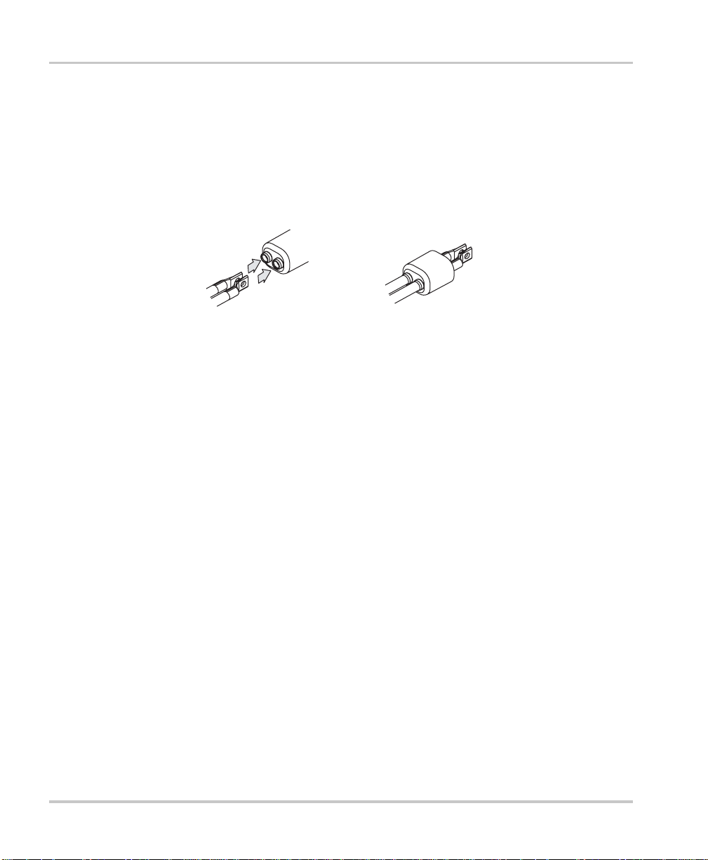
To connect AC wires with the crimp-on butt-splice connector:
Important:
You must exercise care when crimping butt -splice connectors. Use the
crimp tool recommended by the manufac turer for the connec tor used.
a) Using a wire stripper, carefully strip 8 mm (5/16 in.) from the ends of the
two wires be ing connected.
b) Insert one wire into one end of the butt-splice, until the insulation hits the
internal metal crimp section, insert the butt-splice into the crimping tool,
and crimp firmly. The proper location f or the crimp is approximately
1.6 mm (1/16 in.) past where the butt-splice insulation tapers down as
shown.
1/16 “
STRIP 5/16”
CRIMP TOOL
c) Repeat Step b for the othe r en d of the bu tt-sp l ice.
11. Push the AC cable str ain r elief into the electr ical jun cti on box hole unti l it sna ps
into place.
12. When all connections are completed, push the wiring and connectors inside the
wiring compartment. Install the wir ing compartment cover an d fasten with the
supplied blunt-tip screws and lockwashers.
2
1
13. Proceed to “Mounting the Remote Display”.
2–6 975-0187-01-01
Page 33

Mounting the R emote Display
WARNING: Shock hazard
Even if you intend to leave the remote dis play in the shipped orientation in the XC Series,
you must remove the remote dis play and secure it in place by removing the non-stick
backing on the rear and pre ssing the remote display flanges in place. If you do not use the
non-stick backing, the XC Series will not be drip protected.
To accommodate the charger mounting orientation, the remote display can be
removed and turned 180 ° for readability. If you intend to mount the display
remotely, up to 20 m (65 ft), remove the display before mounting the charger and
secure the blank plate to cover the display socket on the unit.
CAUTION
Ensure you are placing the display in the correct orientation before remo ving the adhesive
backing. T he adhesive tape for attaching the remote is extremely strong and you may be
unable to remove it without damaging the dis play or other equipment.
To remove the display:
Installing the XC Series
1. Unplug the display cable from the tel ephone-type connector on the back of the
unit.
2. Release the display cable from the retaining clips on the underside of the unit.
3. Remove the remote display f rom the charger and read and then remove the
warning label that is attached to it.
To secure the display or blank plate on the unit:
1. Choose the display orientation that is appropriate for the charger orientation.
2. Remove the adhesive backing on the back of the display or blank plate .
3. Line up the display or blank plate with the display socket, making sure it is in
the chosen orientati on.
4. Firmly press the flanges in pla ce. Do not press in the middle of the display.
5. Route the display’s North American style telephone-type cable under the unit
and plug the cable into the bottom connector on the rear panel of the unit.
975-0187-01-01 2–7
Page 34

Installation
To remot el y mount the display :
1. Remove the display as described on page 2–7.
2. Secure the blank plate in the display socket as described.
3. Ensure that the extension cable used for the remote display is long enough to
suit the installation. A standard North American style, 4 conductor (RJ-11)
telephone cable exten der is ad equate.
4. Use the enclosed mounting template to cut a hole for the display in the c hosen
mounting surface.
T ake care that there is nothing behind the surface for you to damage.
5. Feed the remote display extension cable through the hole and route it to the
charger. Be careful not to damage the telephone connector locking tab when
routing the cable. You can use some tape to protect the locking tab from
catching on something and breaking off when routing the cable.
6. Remove the adhesive backing on the back of the display.
7. Line up the display with the mounting hole .
8. Firmly press the flanges in pla ce. Do not press in the middle of the display.
9. Once the XC Series is mounte d, plug the cable i nto th e bottom connec tor on th e
rear panel of the XC Series.
10. Proceed to “Mounting”.
Mounting
Mount the XC Series using the mounting slots pro vided.
For marine installat ions, only the mounting configura tions with a check mark in
Figure 1-6 on page 1–1 1 meet the North American and European requirement s.
This is to ensure that any mois ture that may be present will not ent er the XC Series.
Important:
before drilling the pilot holes for mounting the XC Series.
To mount the XC Series:
1. Keep the carton and packing material in case you need to return the XC Series
for servicin g.
2. Ensure that you have selected a mounting surface that is clear, flat and allows
for a minimum of 76 mm (3 in.) of clearance on each end for fan circulation.
2–8 975-0187-01-01
Be sure to measure you r AC and DC cables and pl an th e routing of the cabl es
Page 35
3. Secure the enclosed mounting template to the mounting surface with tape.
4. Drill the six pilot holes for the mounting screws, taking ca re that there is
5. Mount the XC Series using corrosion res istant, #6 (3 mm) round, pan head (or
Grounding
WARN ING: Electric shock hazard
Do not make an ungrounded installation. Have an electrician install a properly grounded
circuit if one is not available. Improper connection ca n res ult in risk of an electri c shock.
The XC Series Battery Charger must be grounded to reduce the risk of electrical
shock. The AC input ground wire of the charger must be properly connected to
ground in accordance with the applicable electrical codes, this is usually a ground
terminal in the AC distribution panel where the branch circuit originates.
Xantrex recommends that you inst all a DC chassis ground (earth) from the ground
stud on the XC Series to the engine negative bus or DC ground bus . The DC chas sis
ground (earth) should not be more than one size smaller than the power conductors,
and must be rated for the battery fuses that are used to protect the DC wiring. Refer
to your local electrica l codes to verify if this is required in your jurisdiction or in
your application.
Installing the XC Series
nothing behind the surfac e that can be damaged by the drill.
similar) screw s.
The top two keyhol e-style mounting holes can be used to hold the XC Series in
place while fa stening the bottom four screws. For se cure, permanent mounting,
use all six mounting slots.
Proceed to “F inal Co n nect io n s”.
975-0187-01-01 2–9
Page 36

Installation
Final Connections
Once the DC cab les , AC cab l es an d XC Series are all in pl ace the fina l con n ecti o n
may be made.
Figure 2-1 shows the connectio n order.
15
4
263
1
14
8
5
10
9
11
13
12
7
Figure 2-1
2–10 975-0187-01-01
DC Wiring Connection Order
Page 37

Final DC Connections
WARNING: Shock hazard
Make sure that the DC fuse or circu it breaker is still open.
To make the last DC connections:
1. Connect the negative cable from the negative ter minal on the battery (if you are
using only one battery or bank), or the negative ground bar or bus (if you are
using more than one battery or bank), to the negative DC terminal on the
XC Series (Figure 2-1). Use a flatwasher, a lockwasher and a nut (5 included in
the installation kit) to secure the connection.
Tight en the nuts to 3 N-m (30 lb-in.) torque and test that the wire is secure.
2. Connect each positive cable to the cor rect positive DC terminal on the
XC Series (Figure 2-1). Use a flatwasher, a lockwasher and a nut (5 included in
the installation kit) to secure the connection.
Tight en the nuts to 3 N-m (30 lb-in.) torque and test that the wire is secure.
3. Connect the free end of ea ch positive cable to the correct positive terminal of
the battery, using sufficient torque as recommended by your battery
manufacturer.
Installing the XC Series
4. Connect the free end of the negative cable to the negative terminal on the
battery, using sufficient torque as recom mended by your battery manufacturer.
Note: If you are using more than one battery, you will need to connect the
negative cable from each of the batteries to the negative ground bar or bus. The
negative ground bar or bus will then have a single negative cable connecting to
the negative charger terminal.
5. Before proceeding, carefully check the wiring polarity – make sure the positive
terminals of the XC Series are connected to the correct terminals of the battery
(fuses or bre akers) and from there to the positive terminals of the battery . Make
sure the negative terminal of the XC Series is c onnected to the battery negative
terminal (or engine negative bus/DC negative bus). Do not reverse the
connections.
6. Install the DC chassis ground (ea rth) from the ground stud on the XC Series to
the engine negative bus or DC ground bus.
7. Connect the BTS cable and the remote display cable to the rear of the charger.
975-0187-01-01 2–11
Page 38

Installation
8. Secure cables in place using tie-wraps, P-clamps or cable straps according to
electrical codes. Coil and tie any extra BTS or remote display extension cable.
9. The DC breakers may be closed or fuses inserted at this time.
Final AC Connections
To make the last AC connections:
1. Complete the installation by routing the AC cable to the AC source.
2. Connect the AC cable to the AC disconnect breaker and ground in accordance
with the color codes on page 2–5.
3. Secure cables in place using tie-wraps, P-clamps or cable straps according to
electrical codes.
Powering Up
Make one last check that all connections and connectors are secure.
The XC Series charger may now be powered up. Switch the AC powe r on at the
source breaker. It is normal to see a 7-10 second delay while the unit powers up.
During this time, the indicator lights on the onboard status panel and the remote
display will not displa y any information.
At very low AC source voltage s (for example, less than 105 VAC) the start up time
will increase proportionally up to as much as 40 seconds.
2–12 975-0187-01-01
Page 39

Instal ling Optional Acce ssories
The XC Series ships with a battery temperature sensor (BTS) and drip protection
rubber boots f or the DC cables.
Battery Temperature Sensor
Xantrex strongly re commends that you install a Battery Te mper ature Sensor (BTS)
to protect your battery and improve charging accuracy. It is best to use a separate
BTS with each individual batte ry bank, to provide optimal charging and protection
of each bank. If no BTS is connected, the charger defaults to the charging
conditions fo r 40 °C (104 °F). At this temper ature the charging voltage is lower to
keep batteries from overcharging; charging will be slower and the batteries will be
slightly unde rcharged.
One BTS is provided with with your XC Series and additiona l battery temperature
sensors may be purchased separately.
To install a BTS:
1. Switch off all devi ces operating from the battery.
2. Connect the ring te rminal on the sensor directly on to the negative battery stud,
or affix the double -sided adhesive backing (included) to the sensor back and
attach the sensor to the side of the battery to be monitored.
Installing Optional Accessories
3. Route the senso r cable to the char ger an d plug it into t he bank 1 (de fault if usi ng
only one BTS), bank 2 or bank 3 connector on the rear panel.
975-0187-01-01 2–13
Page 40
Installation
Drip Protection Rubber Boots
Xantrex recommends that you inst all the supplied rubber boots over the XC Series
DC terminals to provide drip protection.
To install rubber boots:
1. Before making the DC connectio ns to the charge r, feed the rubber boot over the
charger end of the DC cables.
2. Perform all other DC connections a s described in “To install DC wiring:” on
page 2–3.
3. After the DC cables are connected to the charger, slide the boot up the cables
and over the DC terminals. If you are only using one batte ry, slide the spare
boots over the unused DC terminals.
2–14 975-0187-01-01
Page 41

Configuring the XC Series
Once the charger is conne cted to a battery on bank 1 or to AC, it is live and it may
be configured. There will be a short delay of about 15 seconds before the remote
display begins re porting. The remote display will use this time to query the charger
for the current operating conditions.
Configuring the XC Series
If AC was already applied, ens ure that the char ger is in on by pressing
ON/STANDBY
if necessary.
To configure the battery bank type:
1. Press and hold
2. Press
TYPE to select the battery type configuration programm ing mode.
MODE until
set
(setup) is displ ayed.
The XC Series will default to Bank 1 and will show the present battery type
setting.
3. Press
BANK repeatedly to select which bank you are setting up. The bank
indicator light will illuminate to show which bank has been selected.
4. Press
TYPE repeatedly to select the battery type for each bank. When you have
selected a batter y type that is different from the present con figuration, the bank
indicator light fl ashes.
Set th e
TYPE accor ding to the table below:
If your ba ttery is then s elect
Flooded Lead Acid (has removable caps intended for refilling)
GEL (any sealed type except AGM)
Absorbed Glass Mat (AGM)
Lead Calcium
FLa
GEL
AGM
LdC
Custom (if pre-configured at facto r y)
5. Press and hold
ON/STANDBY until
yes
is displayed to store the selec te d battery
CUS
type. If no is displayed, verify that you are setting the correct battery type and
try again.
6. Repeat steps 1 throu gh 4 for all banks a ttached to the XC Series. Each time
yes
is displayed for a newly programmed battery type, the charg er exi ts the
programming mode.
7. At any time during setup, you can press
ON/STANDBY once to cancel the current
change and return to char ging or battery monitoring.
975-0187-01-01 2–15
Page 42

Installation
To configure the charging type:
1. Press and hold
MODE until
set
(setup) is displ ayed.
2. Press
MODE to select 2-stage (
2st
) or 3-stage (
3st
) charging. When you have
selected a c harging type that is different from the present configuration, the
bank indicator light flashes.
See “About Charging” on page 3–2.
3. Press and hold ON/STANDBY until
4. At any time during setup, you can press
yes
is displayed to store the selec ted mode.
ON/STANDBY once to cancel the current
change and return to char ging or battery monitoring.
2–16 975-0187-01-01
Page 43

3
Operation
Chapter 3 describes the operating states and provides
procedures for charging a battery and performing an
equalization.
Page 44

Operation
About Charging
The XC Series has three full current rated, independently controlled outputs which
enable it to charge three different batteries or ba ttery banks. Each output can
accommodate any one of the four allowable battery types, regardl ess of what
battery types are connected to the other outputs. Each output can be in a differe nt
stage of charge, rala tive to the other banks; for exampe, Bank 1 in float, Bank 2 in
absorption and Bank 3 in bulk. Each bank can accommodate a separate battery
temperature sensor. The XC Series can also perform either multiplex (3 stage)
charging, or sequential (2 stage) charging.
Important:
common negative.
The battery banks are not galvanic ally isolated from each other. They sha re a
Multiplex 3-Stage Charging
In multiplex c harging mode the charger will check all qualified battery banks every
15 seconds to determine which bank is most in need of charging. That bank will
then be charge d for the next 15 se conds. Eve ry 15 min utes the c har ger will que ry a ll
outputs and detect which batt ery banks are present and healthy.
The multiplex char ging mode employs the 3-stage charging algorithm: Bulk,
Absorption, and Float. During the Bulk stage the battery is accepting high current.
In the Absorption sta ge the batter y volt age is held consta nt and the curr ent decl ines.
A battery will also "gas" (produce hydrogen and oxygen) during this stage. Finally,
in the Float stage, the charger continues to provide voltage at a lower level to
maintain the battery in a fully charged state. If the re is no load on the battery, it will
typically dra w very littl e cur rent. The c har ger , howeve r , is a ble to provi de cur rent to
its full rating to power DC loads on the batt ery. In float, if bat teries are very new or
a battery is on the low end of the size range and if it is fully char ged to the point
where it will not acc ep t any mo re curr en t, then t he charger wil l enter an adap tiv e
float/no float beha viour where it will alternate between float chargi ng (
resting the battery (
The charger will restart the charging cycl e in the Bulk stage if the battery voltage
drops below 12.5 V (12 V units) or 25 V (24 V units) for 15 minutes. Afte r 21 days,
the charger will automatically restart charging in order to refresh the batte ries.
rdy
).
flo
) and
3–2 975-0187-01-01
Page 45

Sequential 2-Stage Charging
In sequential charging mode the charger will check all battery banks every 15
minutes to determine which banks are prese nt, healthy, and in most in need of
charge. The bank most in need of charge will then be charge d for the next 15
minutes.
The sequential charging mode employs the 2-stage charging algorithm. It is the
same as the 3-stage algorithm except that there is no float stage; after the absorption
stage the charger stops providing voltage and current to the battery and enters a
"rest stage". Like the 3-stage algorithm, the charger will restart the charging cycle in
the Bulk stage if the battery voltage drops below 12.5V (12 V units) or 25 V (24 V
units) for 15 minutes. After 21 days, the charger will automatically restart charging
in order to refresh the batteries.
Charging Overview
The XC Series will perform a battery detection sequence every 15 minutes, or on
reapplication of AC, to determ ine which battery banks are present and health y.
If you connect a batter y when AC is disconnecte d, the remote will not recognize it
until the unit has performe d a battery de tection with AC applied.
To force a battery detection sequence,
About Charging
1. Turn off AC.
2. Wait approximately 20 seconds or until a ll lights on the charger or remote have
gone out .
3. Turn on AC.
The charger will then perform a battery detection when AC is reappli ed
The charger does not charge the banks in a pre-determined sequence. The bank
most in need of charging is the one that receives the charge. For example, if Bank 1
and Bank 2 are both charged, but Bank 1 has a load and Bank 2 does not, then the
charger may rarel y cha rge Ba nk 2.
975-0187-01-01 3–3
Page 46

Operation
Disqualified Batt eries
The XC S eri es can identify when a batt ery will not accep t a charge (bat tery is
damaged) or when it is fully charged (healthy) and does not require further charge.
Batteries that will not accept a charge will be removed (disqua lified) from the
charging se quence un til all banks a re check ed again ( every 15 minute s). A dam aged
battery will contin ue to be disqualified each cycle and the charger will not waste
energy trying to charge it. Under some conditions it is also possible that a healthy
battery that is fully charged but unable to accept current (for example, at the
moment it transit ions from Absor ption to Fl oat or Rest ) will be deemed unabl e to be
charged and temprar ily removed from the charging sequen ce. The charger will enter
an adaptive float/ no flo at beha vio ur w here it will alternate bet w een fl oa t chargi ng
flo
) and resting the battery (
(
rdy
) and the 25% Charge Current indicator light on
the onboard status panel will flash. The battery will be evaluat ed every 15 minutes
and added back to the charging sequence when it is later able to accept char ge.
If disqualification occur s during Bulk or Absorption, the battery is damaged or
there is another charging source present other than the charger itself. The remote
display will show
dis
and the 25% Charge Current indicator light on the onboard
status panel will flash.
Measuring Battery Voltage
Use a voltmeter that has a stated accuracy of 0.5% or better on DC voltage. Place
the probes of the meter directly on the studs or plates of the charger terminals. Do
not probe on the wire lugs or other places in the battery wiring system as this will
introduce error into the measure ment: the charger monitors battery voltage as
measured at the charge r ter min als .
Tem per a ture C ons id er at ion s
Xantrex strongly re commends that you install a Battery Te mper ature Sensor (BTS)
to protect your battery and improve charging accuracy. It is best to use a separate
BTS with each individual batte ry bank, to provide optimal charging and protection
of each bank. If no BTS is connected, the charger defaults to the charging
conditions fo r 40 °C (104 °F). At this temperature the charging voltage is lower to
keep batteries from overcharging; charging will be slower and the batteries will be
slightly unde rcharged.
3–4 975-0187-01-01
Page 47

About Charging
Things to be aware of
When the XC Series is operating, fans and lights (DC loads) may vary in speed or
intensity. This is norm al. The XC Series will not harm any load connected to it as
long as there is a battery present on that bank.
When you initially turn the XC Series on and configure it, it is possible that some
banks may be disqu alified. Because the charger is a ble to detect unhealthy batteries
and disqualify them, batteries that may have appeared healthy be f ore will now be
correctly id entifi ed as ne edi ng at ten tion .
Perform these disqualification checks in the order shown:
1. Wait 15 minutes for the next battery detection cycle. The warning may be
temporary.
2. Verify that the battery meets the m inimum AmpHour rating (XC1524: 30 Ah,
XC2524: 50 Ah, XC3012: 60 Ah, XC5012: 100 Ah)
3. Try adding a small DC load.
4. Replace the battery.
975-0187-01-01 3–5
Page 48

Operation
Charging B atteries
Before you sta rt to charge batteries read the “Important Safety Instructions” on
page v and follow all safety precautions when working with batteries.
To charge your batteries:
1. If possible, disconnect all loads from the battery, by opening a disconnect
switch, or by switching the loads off.
2. Ventilate the area around the batter y thoroughly. Review the charging
instructions supplied by the manufacturer of your batteries and take any steps
required.
3. Apply AC power to the XC Series by closing the AC breaker and/or applying
shorepower or turning the generator on. The indicator ligh ts will blink as an
initializati on sequence runs, last ing typically 10 seconds. After initialization the
charging indicator light illuminates.
During charging, the charging c urrent indicator lights show the total current
being delivered to the sele ct ed battery bank as well as any DC load applied.
4. Re-connect all loads to the bat tery, by closing a disconnec t switch, or by
switching the loads on.
The batteries can be in one of six differe nt stages:
Mode Remote Display
Bulk mode
Absorption mode
Rest mode (2-s tage charging)
Float mode (3-stage charging)
Equalize mode
Battery fault
3–6 975-0187-01-01
bUL
AbS
rdy
FLo
EqU
err
Page 49

Charging Batteries
After charging is complete, the XC Series enters into one of these modes:
Float mode When the ready indicator light illuminates, all batteries are fully
charged and rea dy for use. If you selec ted the 3-s tage cha rgi ng mode, the XC Series
is in float mode and will maintain the batteries’ charge.
Rest mode If you selected the 2-stage charging mod e, the ready indicator light
shows the charger is now in rest mode and is checking ba ttery voltage and elapsed
time since the la st charge cycle .
With either charging mode, the XC Series will begin a charging cycle 21 days after
the last cycle, or when battery voltage drops to below 12.5 V (12 V units) or 25 V
(24 V units) for 15 minutes.
975-0187-01-01 3–7
Page 50

Operation
Equalizing Fl oode d Ba tteries
About Equalizing
The XC Series equalizes only flooded lead-acid or lead-calcium batteries. It does
not equalize sealed lead-ac id batteries since they can be damaged by this process.
In the following conditi ons the remote display will show
not enter equalization mode :
• the battery type is set fo r Gel or AGM
• any battery is not fully charged (a ll three battery banks must be charged to float
or rest stage before equaliz a tion can be activated on any bank)
• there is an active fault on the battery you are trying to charge
Xantrex recommends tha t you run a nor mal char g e cycle on the batte ries be fore you
equalize the m.
WARNING: Explosion hazard
During equalization, the battery generates explosive gases. Follow all the battery safety
precautions listed in this guide. Ventilate the area ar ound the battery thoroughly and ensure
that th ere are no sources of flame or sparks in the vicinity
no
and the XC Seri es wil l
CAUTION: Risk of battery damage
The XC Series cannot automatically determine when to stop the equali zation of a battery.
You must monitor the battery specific gravity throughout equalization to determine the end
of the equalize cycle. The one hour time-out is intended as a safety feature to require the
user to continually re-activate it as necessary after checking ba tteries manually, but may not
be sufficiently short to prevent battery damage.
3–8 975-0187-01-01
Page 51

Equalizing Flooded Batteries
Performing An Equalization
Turn off or disconnect all DC loads on the battery during equalization. The voltage
applied to the battery during e qualization may be above the safe levels for some
loads.
To equal ize your batt eries:
1. Check the battery elec tr olyte level. If necessary, refill with distilled water only.
All the cells should have simil ar electrolyte levels. If the levels are widely
different, it will influence the relative concentration of acid, thereby affecting
the specific gravity measurements.
2. Verify that all banks are in either f loat or rest mode.
3. Press
4. Press
MODE and BANK at the same time.
BANK to select which bank you wish to equalize. The bank indicator light
will flash to show which bank has been select ed.
5. Press and hold
ON/STANDBY to put the XC Series into equalization mode.
You can cancel the equalization request by press ing ON/STANDBY once.
If the battery cannot be equalized, the display will show no.
Check that the battery is floode d and in floa t mode.
EQU
6. When the charger is in equalize mode, the display will show
.
7. Monitor the specif ic gravity of each cell of the battery during equalization with
a battery hydrometer.
The equalize cycle will terminate in one hour.
Check the specific gravi ty of each cell a nd repeat the equalization cycle until
they all meet the battery manufacturer’s specifications for specific gravity or
until the specific gravity stabilizes relative to each other for an hour.
8. The charger automatically exits equalization to float mode or rest mode after 1
hour. To manually exit equaliz ation mode early, press
MODE and BANK at the
same time and then press and hold ON/STANDBY.
You can cancel the manual exit request by pressing ON/STANDBY onc e.
9. When equalization has finished, check the battery electrolyte level. If
necessary, refill with distilled water only.
975-0187-01-01 3–9
Page 52

Operation
Transitioning the XC Series to On, Disabled or Off
There are two ways to turn the XC Series on:
• connect AC power at the source
• press
There are two ways to disable the XC Series:
WARNING: Shock hazard
The XC Series still has live voltage while disabl ed. Even when AC power is removed, if th e
XC Series is co nnecte d to a bat tery on bank 1, the uni t will take powe r from the battery. The
only time the XCSeries is de- energized completely is when both AC and DC are
disconnected.
• disconnect AC power at the source
• press
The XC Series continues to monitor the batteries, but will not charge them.
There is only one wa y to saf ely turn th e X C Series off:
• disconnect the AC power at the sourc e and disc onnect all DC batteries.
ON/STANDBY on the remote display if AC is still connected.
ON/STANDBY on the remote display.
This is the only state where the XC Series is completely discharged.
When the XC Series is disabled or off, the remote display is inactive.
3–10 975-0187-01-01
Page 53
Accessing Charger Information
Accessing Charger Information
The XC Series can give you a lot of inf ormation about the stat us of the charger and
the batteries.
Reading Remote Display and Onboard Status Indicator Lights
The remote display and onboard stat us panel show what is happening during the
charging proce ss and are also helpful in troubleshooting. Refer to Chapter 4,
“Trou bleshooting” for more information about int erpreting the remote display and
onboard status indicator lights.
The remote display is designed to report on the active status of the charger. While
the unit is char ging, the remote display rep orts only on the battery being charged at
that moment. It does not report the status of other batteries.
The Ready light on the onboard status indi cator panel only illuminate s when all
flo
connected banks have reached float (
stage charging. If one of the three batteries has been disqualified before it reaches
float/rest stage, while the others have r eached float (
(
rdy
) of 2-stage charging , the Ready light on the onboard sta tus indica tor panel will
not illuminate.
) of 3-stage charging or rest (
flo
) of 3-stage charging or rest
rdy
) of 2-
975-0187-01-01 3–11
Page 54

Operation
Table 3-1
Reading XC Series Status
Charger Status
Charging in bulk or absorption mode.
Remote display shows scrolling display of charging
state, batte ry voltage in volts and charging current in
amps.
Indicator lights indicate the charging current in % of
full ch arge . A t tr a n s it io n poi n ts w h en th e cu rr en t is
changing, two indicator lights may flash alternately,
then settle into the new charging current reading.
Equalizing.
Charging indicator light flashes once every four
seconds if bank 1 is be ing equa li zed, tw ice ever y four
seconds if bank 2 is being equa lized, and three times
every four seconds if bank 3 is being equalized.
Float mode of three stage charging or rest mode of
two stage ch arging.
All batteries have been fully charged.
A battery has been disqualif ied while in float mode of
three stage charging or rest mode of two stage
charging.
Remote
Display Onboard Status Indica t or Lights
BUL
or
Charging indicator light illuminates
ABS
EQU
FLo
Rdy
FLo or
rdy
Charging indicator light flashes
or
Ready indicator light illuminates
25% current indicator light flas hes
A battery has been disqual ified while in bulk or
dis
25% current indicator light flas hes
absorption mode.
Non-charger fault condition.
Any fault condition that prevents the char ger from
charging one or more bank s, but is not a charger
failure. Remote disp lay shows details of fault.
ERR
BAT
PoL
(example)
Fault indic ator light illuminates
3–12 975-0187-01-01
Page 55

Accessing Charger Information
Table 3-1
Charger Status
Battery too hot faul t
Battery too cold fau lt
Charger fault c ondition.
The charger is damaged, contact service.
Reading XC Series Status
Remote
Display Onboard Status Indicator Lights
ERR
HoT
ERR
CLD
ERR
CHF
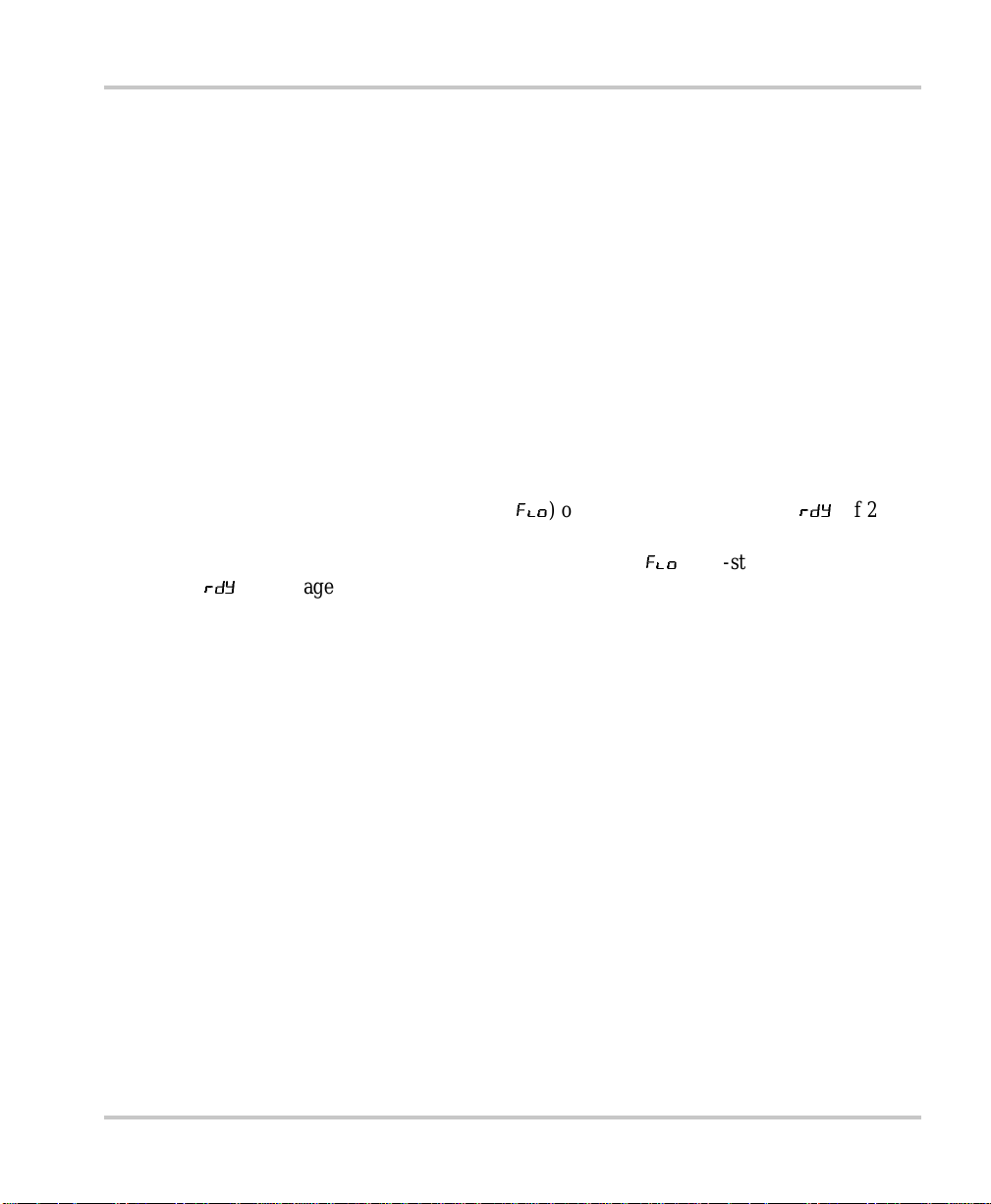
Reporting While Charging or Equalizing
After configuration, the XC Series defaults to a scrolling display. As long as there
are no faults or errors to report, the remote will display the followin g information,
in order, for the bank presently being charged:
• Charging Stage
• Battery Voltage
• Charger Curren t
If there is a fault or warning related to one of the ba nks, the fault or wa rning
information will dis play in the scrolling display befor e the charging state for the
bank presently being charged. Charging for ba nks not in fault will continue (see
“Error Messages on Remote Display” on page 4–4). Charging for the bank in fault
will resume once the fault condi tion is cleared.
Fault indic ator light illuminated
100% current indicator light flashes
Fault indic ator light illuminated
10% current indicator light flas hes
Fault indic ator light flashes
975-0187-01-01 3–13
Page 56

Operation
Reporting While Battery Monitoring
The XC Series is considere d to be battery monitoring if it is experiencing a charger
level fault. If there is a charger leve l fault (affecting all banks), all charging will be
suspended until the charger fault is resolved (see “Error Messages on Rem ote
Display” on page 4–4).
The remote will display all of the fol lowing, in order:
• Highest level charger fault or warning (if present)
• Bank 1 Highest level bank fault or warning (i f present)
• Bank 1 Charging Sta ge
• Bank 1 Battery Voltage
• Bank 1 Charger Curre nt
• Bank 2 Highest level bank fault or warning (i f present)
• Bank 2 Charging Sta ge
• Bank 2 Battery Voltage
• Bank 2 Charger Curre nt
• Bank 3 Highest level bank fault or warning (i f present)
• Bank 3 Charging Sta ge
• Bank 3 Battery Voltage
• Bank 3 Charger Curre nt
Reporting While Disabled
If AC power ha s been disconnected or if you ha ve used the remote display to
disable the XC Series the unit is considered to be disabled. The remote display is
also disabled at this time .
While the XC Series is disabled, you may wish to see the present status of the
banks.
To view the prese nt status of the banks:
◆ Press
If AC power is disconnected, the remote display will show one cycle (similar to the
battery monitor cycle) for each bank that was qualified as pre sent and healthy
during the last batter y detec tion cycle. The remote display will tur n itself off after
one complete cycle.
3–14 975-0187-01-01
ON/STANDBY.
Page 57

◆ Press ON/STANDBY on the optional remote display to initialize another
cycle.
If AC power is con nect ed, the X C Serie s will turn on, check which battery
banks are present and healthy, and begin charging.
While the XC Series is off, and a fault is present, the remote display will
turn itself on approximately once per minu te t o show the fault and then turn
itsel f off.
Using A Generator As Source Power
The XC S eri e s can b e ru n from a regular power source o r from an alte rn ate
power source such as a generator. Refer to Appendix A, “Specif icati ons” for
AC input draw to dete rmine t he siz e of ge nerato r you ne ed. Many g enerator s
provide output voltage that is modified sine wave or modified square wave
(MSW) rather than the true sine wave (TSW) that your utility provides.
The XC Series may be use d with MSW generators but the lifetime may be
reduced somewhat depending on the seve rity of any peak voltage
overshoots, and the severity of waveshape risetimes.
Accessing Charger Information
975-0187-01-01 3–15
Page 58

3–16
Page 59

4
Troubleshooting
Chapter 4 contains information on error codes and
procedures for troubleshooting your XC Series
charger.
Page 60

Troubleshooting
Care and Main ten ance
WARNING: Risk of electric shock
The XC Series contains no user serviceable compon ents. Attempting any kind of service
will void your warrant y. Contact your dealer or the manufacturer for service information.
The XC Series contains solid-state electronic components that require no
maintenance. The best care you can give the unit is to protect it from contact with
liquids, spray, or fumes which may cause corrosion. Disconnect all AC and DC
power and clean the outside of the case and wiring with a damp cloth if you suspect
it has come in contact with battery flui d, sa lt water, ga soline or oil, or other
corrosive mater ial. Periodica lly, check all DC and AC wiring co nnecti ons to be s ure
they have not loosened or deteriorated. Also check all cable clamps to ensure they
are tightly fasten ed.
Loose battery termina ls and lugs expose d to open air cor rode ra pidly. The corrosion
appears as a white powder or granular foam on the terminals and any nearby
exposed metal parts. If it conta cts your skin, it will cause burns unl ess you rinse it
off i mmediately. Most textiles that are exposed to this corrosive event ually dissolve.
To clean battery terminals:
1. Disconnect all loads and charging sources.
2. Using the appropriate tool, remove the negative batte ry cable f irst and re-i nstall
it last.
3. To remove any stubborn residue, sprinkle baking soda directly on the area,
scrub with a wet toothbrush (or othe r soft-bristle brus h), add water as required,
and then rinse.
CAUTION
Take care not to al low any washing solution to enter the battery filling caps in the case of a
flooded batte r y, as any contaminati on into a cell will chemi ca lly damage it.
4. Reconnect the battery cable terminals to the battery lugs and tighten.
5. After tightening the cables, evenly coat all the exposed metal surf aces of the
battery terminals a nd lugs with liquid neoprene. If liquid neoprene is not
available, use a li ght coati ng of anti -corr osion grease or o ther se alant. Do not let
anything come between the mating surf ace s of the lugs and terminals.
4–2 975-0187-01-01
Page 61

Indicator Light Flashing Sequences
Indicator Light Flashing Sequences
Table 4-1
Activity Charger status
Charging ind icator light illuminates The unit is charging in bulk or absorption mode
Charging ind icator light fla shes The unit is performing the equalization charge.
Ready indicato r light illumina tes The unit is either in float mode of three stage
Fault indicator light illuminates Any fault condition that prevents the charger from
Fault indicator light flashes Charger fault condition - remote display shows
Charging curren t indicator lights
illuminate
Charging curren t indicator lights
flash
Charging curren t indicator lights
flash,
Fault indicator light illuminated
Indicator Light Sequences on the XC Series
(Charging indicator light flas hes once every four
seconds if bank 1 is being equalized, twice every
four seconds if bank 2 is being equalized, and
three times every four seconds if bank 3 is being
equalized)
charging or rest mode of two stage charging. All
batteries have been fully charged.
charging one or more banks, but is not a charger
fault condition - remote display shows details of
fault. Example:
polarity detected)
err
followed by
contact service.
These lights indicate the cha rging current. At
transiti on poi nts when the cur rent is changi ng, two
indicator lights may flash alternately, then settle
into t h e n ew charging current reading.
100% indicator light flashes to indicate battery
temperature to o high warning (> 50 °C, 122 °F)
10% indicator light flashes to indicate battery
temperature to o low warning (< 0 °C, 32 °F)
25% indicator light flashes to indicate that a
battery has been disqualified (see page 3–4)
100% indicator light flashes to indicate battery
temperature too high fault (> 55 °C, 131 °F)
10% indicator light flashes to indicate battery
temperature too low fault (< -20 °C, -4 °F)
Err BAT PoL
CHf
(battery reverse
. The charger is damaged,
975-0187-01-01 4–3
Page 62
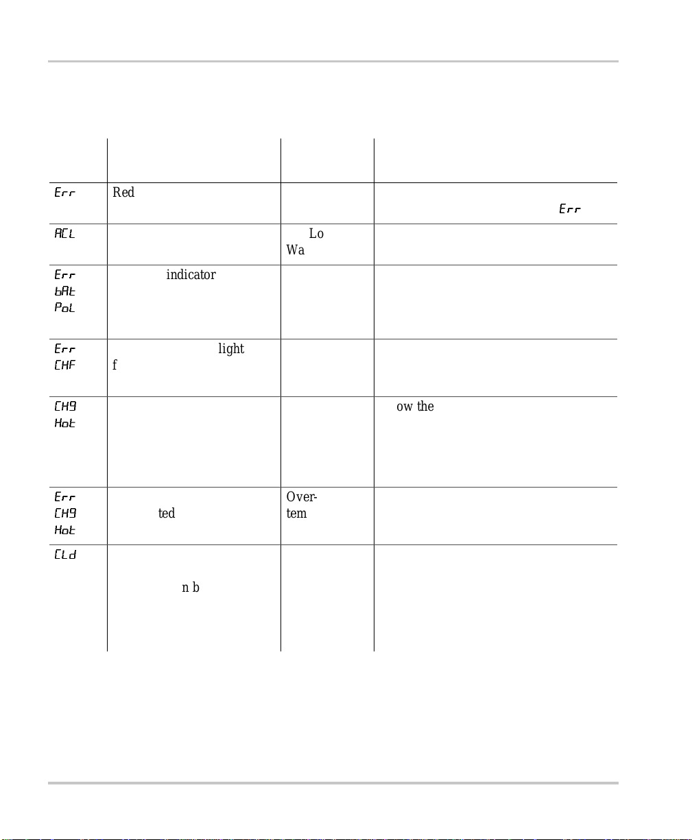
Troubleshooting
Error Messages on Remote Display
Table 4-2
Display
ERR
ACL
Err
bat
PoL
Err
CHf
CHg
Hot
Err
CHg
Hot
Error Messages
Onboard Status Panel
Indicator lights Fault Solution
Red fault in dicator light
flashing or ill um inated
Red fault in dicator light
illuminated
Red fault in dicator light
flashing
Red fault in dicator light
illuminated
Fault A fault has been detected. The fa ult code
will be shown immediate ly after
AC Low
Warning
Reverse
Polarity
Charger
Hardware
Fault
Overtemperature
Warning
Overtemperature
Shutdown
Check AC connections, check AC
availability at source.
Reverse Polarity Battery connected.
Check connections. Ensure correct
polarity (negative connected to negative,
positive c onnected to positive).
Call for service.
Allow the XC Series to coo l . Improve
ventilation or install in cooler location. If
the temperature increases, the XC Series
will enter the fault level and stop
functioning.
Allow the XC Series to coo l . Improve
ventilation or install in cooler location.
Err
.
CLd
4–4 975-0187-01-01
Green 10% indicator light
flashes
Display gre en bank indicator
light for af fected batt ery bank
illuminated
Battery Too
Cold Warning
Allow batteries to warm up before
attem p ti n g to ch arge again. Ch argi n g a
battery that has frozen is a potential
explosion hazard. If the temperature
drops, the XC Series will enter the fault
level and stop char ging the affected bank.
Page 63

Error Messages on Remote Display
Table 4-2
Display
Err
CLd
DIS
HI
Error Messages
Onboard Status Panel
Indicator lights Fault Solution
Red fault in dicator light
illuminated
Green 10% indicator light
flashes
Display gre en bank indicator
light for af fected batt ery bank
illuminated
25% current indicat or light
flashes
Display gre en bank indicator
light for th e affected ba tt e ry
bank illuminated
Battery Too
Cold
Shutdown
Battery
Disqualified
Warning
Over Voltage
Shutdown
Warning
Allow batteries to warm up before
attem p ti n g to ch arge again. Ch argi n g a
battery that has frozen is a potential
explosion ha zard.
Wa it 15 minutes for the next battery
detection cycle . T he warn ing may be
temporary.
Verify that th e batt er y meets th e mini mu m
AmpHour rating (XC1524: 30 Ah,
XC2524: 50 Ah, XC3012: 60 Ah,
XC5012: 100 Ah)
Try ad ding a small DC load .
Replace the bat te r y.
Check battery. Do not charge a battery
rated at more than 12 volt s nominal
(XC3012, XC5012) or 24 volts nominal
(XC1524, XC2524).
Disconnect or turn off other charging
sources such as the alternator or the
charger o n a ge n er a to r wi t h el ec tr ic start.
If the w ar n in g level es ca lates without
being corrected, the XC Series enter the
fault level and stop charg in g the affected
bank.
Err
HI
975-0187-01-01 4–5
Red fault in dicator light
illuminated
Display gre en bank indicator
light for th e affected ba tt e ry
bank illuminated
Over Voltage
Shutdown
Check battery. Do not charge a battery
rated at more than 12 volt s nominal
(XC3012, XC5012) or 24 volts nominal
(XC1524, XC2524).
Disconnect or turn off other charging
sources such as the alternator or the
charger o n a ge n er a to r wi t h el ec tr ic start.
Page 64

Troubleshooting
Table 4-2
Display
Hot
Err
Hot
no
Err
no
Bat
Error Messages
Onboard Status Panel
Indicator lights Fault Solution
Green 100% indicator light
flashes
Display gre en bank indicator
light for th e affected ba tt e ry
bank illuminated
Red fault in dicator light
illuminated
Green 100% indicator light
flashes
Display gre en bank indicator
light for af fected batt ery bank
illuminated
Red fault in dicator light
illuminated
Battery too
Hot Warning
Battery too
Hot Shutdown
Cannot apply
change
No batteries
detected
Allow battery t o cool. Improve venti la tion
or install in cooler location. It may
indicate a shorted cell in the batter y or
excessive water loss. If the temperature
increases, the XC Series will enter the
fault level and stop charging the affected
bank.
Allow battery t o cool. Improve venti la tion
or install in cooler location. It may
indicate a shorted cell in the batter y or
excessive water loss.
The operation you have tried to execute
cannot be c ompleted.
The charger did not detect any batteries.
4–6 975-0187-01-01
Page 65

Problem Solv in g
If the remote display is not funct ioning, troubleshoot your XC Series using the
tables below. In the event that you have a problem with your XC Series, the
following ta bles wil l help you to i dentify t he problem and off er possible s olutions t o
the problem.
Symptom
Indicator lights do not illuminate when charger is connected to AC power.
Possible Cause Solution
Problem Solving
Symptom
No power at AC source and no
battery conne cted on bank 1
Defective AC wiring
Charger level f ault
Ensure that pow er is available at th e source and a
battery or bank is connected on bank 1
Replace wiring
Call for service
Fault indicator light illuminates. XC Series stops func tioning.
Possible Cause Solution
XC Series does not detect battery
for one of following reasons:
• poor connection
• reverse pola r ity connection
• damag ed w ir i ng
XC Ser i es in t e rn al temper ature
too hot
Check quality of battery connection and wires.
Ensure correct polarity (negative connec ted to
negative, positive connected to positive).
Allow the XC Series to cool. Improve ventilation or
install in cooler location.
975-0187-01-01 4–7
Page 66

Troubleshooting
Symptom
Fault indicator light flashes. XC Series stops functioning.
Possible Cause Solution
XC Series hardware failure Call for service
Symptom
Fault indicator light illuminates. 100% indicator light flashes.
Possible Cause Solution
Symptom
Symptom
Battery temperature is too hot for
safe charging.
Allow battery to co ol. Improve ventilation or
install i n cooler location. It may indica te a shorted
cell in the battery or excessive water loss.
Fault indicator light illuminates. 10% indicator light flashes.
Possible Cause Solution
Batt er y te mp er ature is too co ld for
safe charging.
Allow batteries to warm up before attempting to
charge again. Charging a battery that has frozen is
a potential explosion hazard.
XC Series completes a charging cycle, but the battery volt age seems (about 2 volts)
too low.
Possible Cause Solution
Battery has a shorted cell. Check the battery.
V erify you are attempting to charge a battery correctly
rated at 12 volts nominal (XC3012, XC5012) or 24
volts nominal (XC1524, XC2524). Re -check the
battery voltag e with al l lo ads removed a nd the batte ry
is at rest for about an hour.
4–8 975-0187-01-01
Page 67

Symptom
Problem Solving
The XC Series appears to be tak ing too long to char ge batt ery. Ready indicator light
does not illuminate aft er 24 hours of charging.
Possible Cause Solution
Symptom
Battery capacity is too high for the
XC Series model.
Load connected to bat tery is
draining charge current so that
battery does not recharge.
Battery has a damaged cell.
Use a high er capacity charger.
Disconnect load or switch load off.
Replace battery.
The XC Series will not transition to equalization mode.
Possible Cause Solution
Battery is the wrong type, or set to
the wrong type to equalize.
Not all batteries are fully charged.
Verify battery type is set to Gel or AGM. These
battery types cannot be equalized.
Wait for all batteries to be in float (
charging or rest (
attempting to e qualize (t he ready indicat or light will
illuminate).
rdy
flo
) of 3-sta ge
) of 2-stage charging before
An active fault is present on the
bank you are attempting to equalize.
975-0187-01-01 4–9
Clear the active fault (see Table 4-2 on page 4–4)
Page 68

4–10
Page 69

A
Specifications
Appendix A details the specifications for the
XC Series.
Page 70

Specifications
Physica l Specific ations
Dimensions Base unit: 367 mm x 240 mm x 106 mm
Remote Display: 118 mm x 41 mm x 32 mm
Weight 5.7 kg (12.6 lbs)
AC input connec tions Two color-coded No. 16 AW G wires (L, N) and one
No. 18 AWG (G) minimum 152 mm (6 in.) long in a separate
AC wiring enclosure with 21.3 mm (0.84 in.) hole provision for
connection of a ½ inch North American "trade size" cable c lamp
or conduit hub o r in te rnation al PG 13. 5 or PG16 o r M20 gland o r
cable strain relief fitting.
DC output connections Four right-angle M6 studs (3 positives and 1 common
negative) for battery cable ring terminals and one M6 mm DC
equipment ground
Electric al Specifications
14.45 in. x
4.65 in. x 1.6in. x 1.26 in.
9.45 in. x 4.17 in.
Number of battery bank outputs 3 isolated, independently controlled outputs
Nominal battery voltage 12 V units: 12 VDC
24 V units: 24 VDC
Normal operating output range 12 V units: 0 – 16 VDC
24 V units: 0 – 32 VDC
Nominal operating AC voltage 110 – 240VAC
Rated DC output current (total) XC3012: 30 A (up to 15 V)
XC5012: 50 A (up to 15 V)
XC1524: 15 A (up to 30 V)
XC2524: 25 A (up to 30 V)
Absorption voltag e (in VDC for
XC3012 and XC5012)
(Multiply VDC by 2 to get the
absorption voltage for XC1524
and XC2524)
A–2 975-0187-01-01
Flooded 13.7 14.4 15.1
Gel 13.5 14.2 14.9
AGM 13.8 14.3 14.8
Lead-calcium 14.8 15.5 16.0
50 °C (122 °F) 25 °C (77 °F) <0°C (32°F)
Page 71

AC Input Specifications
Float voltage (in VDC for XC3012
and XC5012)
(Multiply VDC by 2 to get the
float voltage for XC1524 and
XC2524)
Equalize mode current 50% rate d output
Equalize mode—maxi mum out put
voltage
Off-state current dr aw (with
remote installed)
AC Input Specific ations
AC input voltage range 100 – 260 VAC at full power
50 °C (122 °F) 25 °C (77 °F) <0°C (32°F)
Flooded 12.8 13.5 14.2
Gel 13.1 13.8 14.5
AGM 12.9 13.4 13.9
Lead-calcium 12.8 13.5 14.2
XC3012: 16.0 VDC
XC5012: 16.0 VDC
XC1524: 32.0 VDC
XC2524: 32.0 VDC
XC3012: <20 mA
XC5012: <20 mA
XC1524: <15 mA
XC2524: <15 mA
90 – 105 VAC at 80% restricte d load
Note: Charg er may not s tart with input voltage
<100 VAC
Maximum AC input current at 100 VAC at 184 VAC
XC3012: 6 AAC XC3012: 4.3 AAC
XC5012: 10 AAC XC5012: 5.7 AAC
XC1524: 6 AAC XC1524: 4.3 AAC
XC2524: 10 AAC XC2524: 5.7 AAC
Power factor at rated load ≥0.95
Frequency 47 – 63 Hz
Efficiency – peak 12 V units: 80% @ 120 VAC, 83% @ 230VAC
24 V units: 85% @ 120 V AC, 87% @ 230 VAC
Surge protection Line-to-neutral surge protector ra ted at 275 VAC
975-0187-01-01 A–3
Page 72

Specifications
Temperature Specifications
Nominal ambient 25 °C (77 °F)
Operating range 0 – 50 °C (32 – 122 °F)
Current de-rating approx. 2% (Imax) / °C (50 – 65 °C) (122 – 149 °F)
Storage -40 – 80 °C (-40 – 176 °F)
Humidity 5 – 95%, RH non-condensing
Protection Features
Battery reverse polarity N o damage incurred by reverse polarity.
Safe non-operating battery voltage 35 VDC maximum
Over-voltage limits The XC Series will stop char ging any bank t hat ha s a
Output current limit XC3012: 30 – 33 ADC
voltage greater than + 0.5 V over the tempera ture
compensated absorption voltage. It will restart when
this voltage is + 0. 2 V.
XC5012: 50 – 55 ADC
XC1524: 15 – 16.5 ADC
XC2524: 25 – 27.5 ADC
Over-temperature Internal charger temperature is measured. Unit shuts
down and restarts as follo ws:
• Over-te mperature shutdown at 75 °C (167 °F)
• Over-te mperature resta rt at 70 °C (158 °F)
Current derating in ambient
temperatures
Battery over-temperature
protection
A–4 975-0187-01-01
Rated current to 50 °C (122 °F)
2%/ °C derating above 50 °C (122 °F)
Battery temperature, as sensed by the battery
temperat ur e sensor (if installed), results in the
charger no longer charging the individual battery or
bank at a ba ttery temperature of 55 °C (132 °F).
Page 73

Approvals
Safety CSA/NRTL approved to CSA107.2 and UL1236, including the marine
EMC FCC Cl ass B
Other KKK-A-1822 Rev D - Federal Specification for the Star-of-L ife Ambulance
Approvals
supplement, igni tion protection, and UL1564
EN60335-1, EN60335-2-29 Battery Chargers
ISO 8846: Ignition Protection for Small Craft
ABYC E11 - Alternating Current and Direct Current Electrical Systems on
Boats
ABYC A20 - Battery Charging Device s
NFPA70/1996 US NEC for home and RV installation requirements
CE marked, meeting EMC Directive 89/336/EEC (referencing EN55014-1,
EN55014-2, EN61000-3-2, EN61000-3-3, EN61000-4-2, EN6 1000-4-3,
EN61000-4-4, EN61000-4- 5, EN61000-4-6, EN61000-4-11)
CISPR25 (similar to SAE J1113-41) Class 1 on DC outpu ts
975-0187-01-01 A–5
Page 74

A–6
Page 75

Warranty and Product Information
Limited Warranty for:
Xantrex XC3012 Battery Charger
Xantrex XC5012 Battery Charger
Xantrex XC1524 Battery Charger
Xantrex XC2524 Battery Charger
"XC Series"
What does this warranty cover and how long does it last? This Limited Warranty is provided by
Xantrex Technology Inc. ("Xantrex") and covers defects in workmanship and materials in your Xantrex XC Series
product . This warranty lasts fo r a Warranty Period of 24 months from the date of purchase at point of sale to you,
the original end user customer. This Limited Warranty is tra nsferable to subsequent ow ners but only for the
unexpir ed portion of the Warranty Period.
What will Xantrex do? Xantrex will, at its option, repair or replace the defective produ ct free of charge,
provided that you notify Xantrex of the product defect within the Warranty Period, and provided that Xantrex
through inspection establis hes the existence of such a defect and that it is covered by this Limited Warranty.
Xantrex will, at its option, use new and/or reconditioned parts in performing warranty repair and building
replacem ent products. Xantrex reserv es the right to use parts or products of original or improved design in the
repair or replacement. If Xantrex repairs or replac es a product, its warranty continues for the remaining p ortion of
the original Warran ty Period or 90 days from the date of the ret u rn shipment to the customer, whichever is greater.
All replaced products and all part s removed from repaire d products become the property of Xantrex.
For Unite d States and Canada retur ns, Xantrex covers both parts and labor necessary to repair the product, and
return shipment to the customer via a Xantrex-selected non-expedited surface freight within the contiguous United
States and Canada. Alaska and Hawai i are excluded. Contact Xantrex Cust omer Service for details on our freight
policy for return shipments out side of the contiguous United States and Canada.
How do you get s ervice ? If your produc t requires troublesh ooting or warranty servi ce, contact your dealer. If
you are una ble to contact your dealer, or the dealer is unable to pr ovide service, contac t X antrex directly at:
Phone: 1 800 670 0707 (toll fr ee N orth America)
Fax: 1-800 994 7828 (toll free North Ameri ca)
Email: customerservice@xantrex.com (North America and rest of world)
Direct returns may be performed according to the Xantrex Return Material Authoriz ation Policy described in your
product ma nual. For some products, Xantrex maintains a networ k of regional Authori zed Servic e Centers. Call
Xantrex or check our website to see if yo ur product can be repaired at one of these facilities.
In any warranty claim, dated proo f of purchase must accompany the product and the product must not have been
disassem bled or modified withou t prior written authorization by X antrex.
Proof of purchase may be in any one of the following forms:
• The dated purchase receipt from the original purchase of the product at point of sale to the end user, or
• The dated dealer invoice or purchase receipt showing original equipment manufacturer (OEM) status, or
• The dated invoice or purchase receipt showing the product exchanged under warranty
+34 93 470 5330 (Europe)
1 360 925 5097 (direct and rest of world)
+34 93 473 6093 (Europe)
1 360 925 5143 (direct and rest of world)
support.europe@xantrex.co m ( E urope)
975-0187-01-01 WA–1
Page 76

Warranty and Product Information
What does this warr anty not cover? This Limited Warranty does not cover norm al wear and te ar of the
product or costs related to the re m oval, installation, or troubleshooting of the custome r's electrical systems. This
warrant y does not apply to and Xantrex will not be responsible for any defect in or damage to :
a) the product if it ha s been misused, neglected, improperly installed, physically damaged or altered, eithe r
internally or externally, or damaged from improper use or use in an unsuitable environment;
b) the prod uct if it has been subjected to fire, water, exces sive corrosion, biological infestat ions, or input voltage
that creates operating condit ions beyond the maximum or mini mum limits listed in the Xantrex product
specifications including high input voltage from generators and lightning strikes;
c) the product if repairs have been done to it other than by Xantrex or its aut horized service centers (hereafter
"ASCs");
d) the produ ct if it is used as a component part of a product expressly warranted by another manufa cturer;
e) the produc t if its origin a l id en tificati o n (tr ade-mark, seria l nu m b er ) m a rk in g s ha v e be e n de fa ced, alte re d , or
removed.
DISCLAIMER OF WARRANTY
THIS LIMITED WARRANTY IS THE SOLE AND EXCLUSIVE WARRANTY PROVIDED BY XANTREX IN
CONNECTION WITH YOUR XANTREX PRODUCT AND IS, WHERE PERMITTED BY LAW, IN LIEU OF
ALL OTHER WARRANTIES, CONDITIONS, GUARANTEES, REPRESENT ATIONS, OBLIGATIONS AND
LIABILITIES, EXPRESS OR IMPLIED, STATUTORY OR OTHERWISE IN CONNECTION WITH THE
PRODUCT , HOWEVER ARISING (WHETHER BY CONTRACT, TORT , NEGLI GENCE, PRI NCIPLES OF
MANUF ACTURER'S LIABILITY, OPERATION OF LAW, CONDUCT, STATEMENT OR OTHERWISE),
INCLUDING WITHOUT RESTRICTION ANY IMPLIED WARRANTY OR CONDITION OF QUALITY,
MERCHANT ABILITY OR FITNESS FOR A PARTICULAR PURPOSE. ANY IMPLIED WARRANTY OF
MERCHANT ABILITY OR FITNESS FOR A PARTICULAR PURPOSE TO THE EXTENT REQUIRED
UNDER APPLICABLE LAW TO APPLY TO THE PRODUCT SHALL BE LIMITED IN DURATION TO THE
PERIOD STIPULATED UNDER THIS LIMITED WARRANTY.
IN NO EVENT WILL XANTREX BE LIABLE FOR ANY SPECIAL, INDIRECT, INCIDENTAL OR
CONSEQUENTIAL DAMAGES, LOSSES, COSTS OR EXPENSES HOWEVER ARISING WHETHER IN
CONTRACT OR TORT INCLUDING WITHOUT RESTRICTION ANY ECONOMIC LOSSES OF ANY KIND,
ANY LOSS OR DAMAGE TO PROPERTY, ANY PERSONAL INJURY, ANY DAMAGE OR INJURY
ARISING FROM OR AS A RESULT OF MISUSE OR ABUSE, OR THE INCORRECT INSTALLA TION,
INTEGRATION OR OPERATION OF THE PRODUCT.
Exclusions If this product is a consumer product purchased in the United States, federal law does not allow an
exclus ion of implied warranties. To the extent you are entitled to implied warranties under federal law, t o the extent
permitted by applicable law they are limited to the duration of this Lim ited Warranty. Some states do not allow
limitations or exclusions on implied warranties or on the duration of an implied w arranty or on the limitation or
exclusion of inci dental or consequentia l damages, s o the above lim itation(s) or exclus ion(s) may not apply to you.
This Lim ited Warranty gives you specific legal rig hts. You may have other rights which may vary depending on the
country, province, or state.
WITHOUT LIMITING THE GENERALITY OF THE FOREGOING, UNLESS SPECIFICALLY AGREED TO
BY IT IN WRITI NG, XANTREX
(a) MAKES NO WARRANTY AS TO THE ACCURACY, SUFFICIENCY OR SUITABILITY OF ANY
TECHNICAL OR OTHER INFORMATION PROVIDED IN MANUALS OR OTHER DOCUMENTATION
PROVIDED BY IT IN CONNECTION WITH THE PRODUCT; AND
(b) ASSUMES NO RESPONSIBILITY OR LIABILITY FOR LOSSES, DAMAGES, COSTS OR EXPENSES,
WHETHER SPECIAL, DIRECT, INDIRECT, CONSEQUENTIAL OR INCIDENTAL, WHICH MIGHT
ARISE OUT OF THE USE OF SUCH INFORMATION.
THE USE OF ANY SUCH INFORMATION WILL BE ENTIRELY AT THE USER'S RISK.
WA–2 975-0187-01-01
Page 77

WARNING: LIMIT ATIONS ON USE
Please refer to your product user manual for limitations on uses of the product. Specifically, please note that the
Xantrex Battery Charger is not intended for use in connection w ith life support systems and Xantrex makes no
warranty or representation in connection with any use of the product for such purposes.
Xantrex Technology, Inc.
8999 Nelso n Way
Burnaby, British Columbia
Canada
V5A 4B5
Return Material Authorization Policy
If your product requires warranty service, please contact your dealer first. If you are unable to contact your dealer ,
or your dea ler is unable to provide service, contact Xant rex.
Before ret ur ning a p ro duct dire ct ly to Xant re x you must obtai n a Return Mate ri al A uthor iz atio n (RMA ) num ber a nd
the corr ect factory "Ship To" address. Product shipments will be refused and returne d at your expe nse if they are
unautho rized returned without an RMA number clearly marked on the outside of the shipping box, if they are
shipped collect, or if they are shipped to the wrong location.
When you contact Xantrex to obtain service, please have yo ur instruction manual ready for reference and be
prepared to supply:
• The serial number of your product
• Information about the installation and use of the unit
• Information about the failure and/or reason for the return
• A copy of your dated pro of of purchase
When you ship:
1. Package the unit safely, preferably using the original box and packing materials. Please ensure that your product is shipped
fully insured in the original packaging or equivalent. This warranty will not apply where the product is damaged due to
improper packaging.
2. Include the following:
• The RMA number supplied by Xantrex Technology Inc clearly marked on the outside of the box.
• A return address w her e the unit can be shipped. Post office boxes are not acceptable.
• A contact telephone number where you can be reached during work hours
• A brief description of the problem
Please contact Xantrex for details of the freight policy for your country of purc hase. For United States and Canada
returns, ship the unit prepaid to the address provided by your Xantrex customer service representative.
If you are returning a product to a Xantrex facility in North America from outside of the USA or Canada: In
addition to the above, you MUST include return freight fu nds and are fu lly responsible for all documents, duties,
tariffs, and deposits.
If you are returning a product to a Xantrex Authorized Service Center (ASC): A Xantrex return material
authorization (RMA) number is not required. However, you must contact the ASC prior to returning the product or
presenting the unit to verify any return procedures that may apply to that particular facility.
975-0187-01-01 WA–3
Page 78

Warranty and Product Information
Information About Your System
As soon as you op en your Xantrex XC3012, XC5012, XC1524 or XC2524 Battery Cha rger package, record the
followi ng information and be sure to keep your proof of purchase.
❐ Serial Num ber
❐ Purchased From
❐ Purchase Date
If you nee d to co nt ac t C us to m e r Se r vi ce , please re co r d th e fo ll owing det ai ls before cal lin g . Th i s in fo rm a t ion will
help our r epresentatives give you better service.
❐ T ype of installation
❐ Length of time charger has been installed
❐ Battery/battery bank size
❐ Battery typ e (e.g. flooded, sealed gel cell, AGM)
❐ DC wiring size and length
❐ Description of light indicators or remote display
readout
❐ Appliances operat ing when problem occurred
❐ Desc ription of probl e m
_________________________________________________________________________________________
_________________________________________________________________________________________
_________________________________
_________________________________
_________________________________
___________________________________________
___________________________________________
___________________________________________
___________________________________________
___________________________________________
___________________________________________
___________________________________________
___________________________________________
___________________________________________
WA–4 975-0187-01-01
Page 79

Page 80

Xantrex Technology Inc.
Phone: 1 800 670 0707 (toll free North America)
+34 93 470 5330 (Europe)
1 360 925 5097 (direct and rest of world)
Fax: 1-800 994 7828 (toll free North America)
+34 93 473 6093 (Europe)
1 360 925 5143 (direct and rest of world)
Email: customerservice@xantrex.com (North America)
support. europe@ xantrex.com (Europe)
customerservice@xantrex.com (rest of world)
975-0187-01-01
Printed in Canada
 Loading...