

Page 1
™
TM500A
Battery Status Monitor
Installation &
Operator’s Guide
Page 2

About Xantrex
Xantrex Technology Inc., is a world-leading supplier of advanced power
electronics and controls with products from 50 watt portables to 1 megawatt
utility-scale systems for wind, solar, batteries, fuel cells, microturbines, and
backup power applications in both grid-connected and stand-alone systems.
Xantrex products include inverters, battery chargers, programmable power
supplies, and variable speed drives that convert, supply, control, clean, and
distribute electrical power.
Trademarks
Trace is a trademark of Xantrex Technology Inc. Xantrex is a registered
trademark of Xantrex Technology Inc.
Notice of Copyright
Xantrex TM500A Battery Status Monitor © May 2001 Xantrex Technology.
All rights reserved.
Disclaimers
While every precaution has been taken to ensure the accuracy of the
contents of this guide, Xantrex Technology Inc., assumes no responsibility for
errors or omissions. Note as well that specifications and product functionality may change without notice.
Since the use of this manual and the conditions or methods of installation, operation, use and maintenance of the unit are beyond the control of
Xantrex Technology Inc., the company does not assume responsibility and
expressly disclaims liability for loss, damage, or expense arising out of or any
way connected with such installation, operation, use, or maintenance.
Due to continual improvement through product updates, photographs
and/or illustrations used in this manual may not exactly match your unit.
Xantrex Technology Inc., reserves the right to update this product without
notice or releasing an updated manual when fit, form or function are not
affected.
Date and Revision
May 2001, Revision A
Part Number
973-0012-01-02
Contact Information
Web: www.xantrex.com
Email: tracewarranty@traceengineering.com
Phone: 360/435.8826
Fax: 360/474.0616
© 2001 Xantrex Technology Inc.
P/N 973-0012-01-02 Rev. A 05/01
Page 3
Table of Contents
1.0 INTRODUCTION ............................................................... 1
The TM500A .......................................................................................... 1
Unpacking and Inspection ..................................................................... 2
TM500A (12/24 Volt) ............................................................................. 2
TM500A - NS (12/24 Volt) ..................................................................... 2
TM48 (48 Volt) ....................................................................................... 2
2.0 INSTALLATION ................................................................3
Required Tools ....................................................................................... 3
Pre-Installation ....................................................................................... 3
Mounting ................................................................................................ 3
Surface Mounting .............................................................................. 4
Flush Mounting .................................................................................. 6
Extended Length Installations ........................................................... 8
Deltec™ Shunt ...................................................................................... 9
Mounting/Wiring the Shunt ................................................................ 9
Mounting Circuit Board to an Existing Shunt .................................. 10
Connecting the Shunt Board ........................................................... 11
3.0 CONFIGURATION ........................................................... 12
Setup ................................................................................................... 12
Restoring the Factory Defaults ........................................................... 12
Setting Parameters .............................................................................. 13
Charge Efficiency %.......................................................................... 14
Setting the Charge Efficiency Factor ............................................. 14
Amp Hours Ah.................................................................................... 15
Setting the Amp Hours .................................................................... 15
CHARGED Indicator Setup ............................................................ 17
Trigger on Voltage Only ..................................................................... 17
Trigger on Voltage and Amperage .................................................. 19
Trigger on Voltage and Time ........................................................... 21
Charger Considerations .................................................................. 23
Relay Chargers ........................................................................... 23
Taper Chargers ........................................................................... 23
Three-stage Chargers ................................................................ 23
Low-Voltage Indicator V................................................................... 24
Configuring the Low-Voltage Alarm ............................................... 24
© 2001 Xantrex Technology Inc.
P/N 973-0012-01-02 Rev. A 05/01
i
Page 4

Table of Contents
(continued)
4.0 OPERATION ................................................................... 25
Indicators and Controls ....................................................................... 25
Buttons ................................................................................................ 25
Select Button ................................................................................... 25
Reset Button .................................................................................... 25
INVERTER ON/OFF Button .............................................................. 25
Basic Meters ....................................................................................... 26
Available Meters ............................................................................. 26
% (state-of charge) .................................................................... 26
V (Volts) ...................................................................................... 26
A (AMPS) ..................................................................................... 26
Ah (AMP HOURS) ....................................................................... 27
Power Saving Mode ........................................................................ 27
Data Monitors ...................................................................................... 28
Reminders and Indicators ................................................................... 30
Amp-hour Reminder ........................................................................ 30
Low-Voltage Indicator..................................................................... 31
CHARGED Indicator ......................................................................... 32
5.0 TROUBLESHOOTING .................................................... 33
6.0 SERVICE INFORMATION ............................................... 34
7.0 SPECIFICATIONS .......................................................... 35
8.0 WARRANTY.................................................................... 36
ii
© 2001 Xantrex Technology Inc.
P/N 973-0012-01-02 Rev. A 05/01
Page 5

IMPORTANT SAFETY INSTRUCTIONS
This manual contains important safety instructions that should be followed
during the installation and maintenance of this product.
To reduce the risk of electrical shock, and to ensure the safe installation and
operation of this product, the following safety symbols have been placed
throughout this manual to indicate dangerous conditions and important safety
instructions.
WARNING - A dangerous voltage or condition exists in this area.
Use extreme caution when performing these tasks.
AVERTISSEMENT - Une tension ou condition dangereuse existe dans
cette zone. Faire preuve d’extrême prudence lors de la réalisation de
ces tâches.
CAUTION - This procedure is critical to the safe installation or
operation of the unit. Follow these instructions closely.
ATTENTION - Cette procédure est essentielle à l’installation ou
l’utilisation de l’unité en toute sécurité. Suivre ces instructions de
près.
NOTE - This statement is important. Follow instructions closely.
NOTE - Cette déclaration est importante. Suivre les instructions de
près.
• All electrical work must be done in accordance with local, national,
and/or international electrical codes.
• Before installing or using this device, read all instructions and cautionary
markings located in (or on) the TM500A, the manual, the batteries, the
inverter, the PV array, etc.
• Do not expose this unit to rain, snow or liquids of any type. This product is
designed only for indoor mounting.
• To reduce the chance of short-circuits when installing or working with the
inverter, the batteries, or the PV array, use insulated tools.
• Remove all jewelry such as rings, bracelets, necklaces, etc., while
installing this system. This will greatly reduce the chance of accidental
exposure to live circuits.
• The inverter contains more than one live circuit (batteries, PV array, and
AC). Power may be present at more than one source.
• This product contains no user-serviceable parts. Do not attempt to repair
this unit.
© 2001 Xantrex Technology Inc.
P/N 973-0012-01-02 Rev. A 05/01
iii
Page 6

BATTERY SAFETY INFORMATION
• Always wear eye protection, such as safety glasses, when working with
batteries.
• Remove all loose jewelry before working with batteries.
• Never work alone. Have someone assist you with the installation or be
close enough to come to your aid when working with batteries.
• NEVER smoke in the vicinity of a battery or generator.
• Always connect the batteries first, then connect the cables to the inverter
via a DC disconnect switched OFF. This will greatly reduce the chance of
spark in the vicinity of the batteries.
• Use insulated tools when working with batteries.
• When connecting batteries, always verify proper voltage and polarity.
• Do not short-circuit battery cables. Fire or explosion can occur.
• In the event of exposure to battery electrolyte, wash the area with soap
and water. If acid enters the eyes, flood them with running cold water for
at least 15 minutes and get immediate medical attention.
iv
SAVE THESE INSTRUCTIONS
© 2001 Xantrex Technology Inc.
P/N 973-0012-01-02 Rev. A 05/01
Page 7

1.0 INTRODUCTION
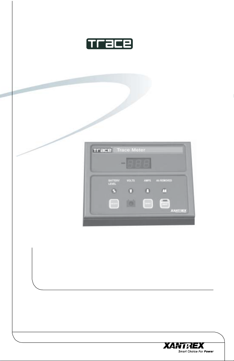
The TM500A
The TM500A features six data monitoring functions and three indicators
including:
• State of charge/amp-hour content (full or percent of capacity)
• State of charge/voltage (real-time voltage level, historical high and low
system voltage)
• Amps (real-time amps, total charging amps, total load amps)
• Amp hours removed
• Days since fully charged
• Cumulative amp hours
• Recharge indicator
• Low-voltage indicator
• Full-charge indicator
The unit is configurable for specific system or application functions such
as setting the CHARGED indication parameters, battery capacity, charging
efficiency, low-battery warning conditions and a recharge reminder. The
TM500A can monitor any battery supply from approximately 8 to 65 volts,
track energy consumption and estimate remaining battery life.
In addition to its status monitoring features, the unit can act as a remote
control, switching the inverter OFF or ON (only on inverters incorporating an
RC4/RC8 compatible remote control jack).
The TM500A operates on 12-, 24-, or 48-volt battery systems (48-volt
systems require an optional shunt board).
© 2001 Xantrex Technology Inc.
P/N 973-0012-01-02 Rev. A 05/01
14.2
Figure 1-1
The TM500A
1
Page 8

1.0 INTRODUCTION
Unpacking and Inspection
Upon receiving the TM500A, check that the following items are included.
TM500A (12/24 Volt)
• TM500A (meter panel, adaptor and mounting bracket)
• Manual
• 50-foot communications cable
• Deltec™ 500 amp/50 mV shunt
• 12/24 volt shunt-printed circuit board with in-line 2-amp fuse
TM500A - NS (12/24 Volt)
• TM500A (meter panel, adaptor and mounting bracket)
• Manual
• 50-foot communications cable
• Shunt-printed circuit board with in-line 2-amp fuse
TM48 (48 Volt)
• 48-volt shunt-printed circuit board with in-line 2-amp fuse
2
© 2001 Xantrex Technology Inc.
P/N 973-0012-01-02 Rev. A 05/01
Page 9

2.0 INSTALLATION
Required Tools
• Phillips screw driver
• 3/32" and 3/16" drill bits
• Hole saw
If the TM500A will also function as a remote control (INVERTER ON/OFF),
an additional cable must be ordered. Available lengths are:
10 feet–TC/10 25 feet–TC/25
50 feet–TC/50 100 feet–TC/100
Pre-Installation
Before installing the TM500A, read all instructions and cautionary
markings located in this manual. The unit should be mounted in a clean, dry,
protected environment.
Determine the wire route to the batteries (and inverter, if the remote
INVERTER ON/OFF function is desired).
NOTE: Check for existing electrical, plumbing or other potential
areas of accidental damage prior to making cuts in structural
surfaces.
Mounting
The unit can be surface mounted (using the adaptor supplied) or flush
mounted into a rectangular opening. Provide at least one inch clearance
behind the meter circuit board for the cabling when flush mounting.
The TM500A ships in three sections:
• TM500A
• Adaptor for surface mounting
• Mounting Bracket
© 2001 Xantrex Technology Inc.
P/N 973-0012-01-02 Rev. A 05/01
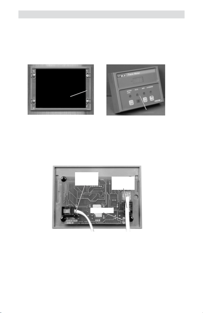
Trace Meter
Panel
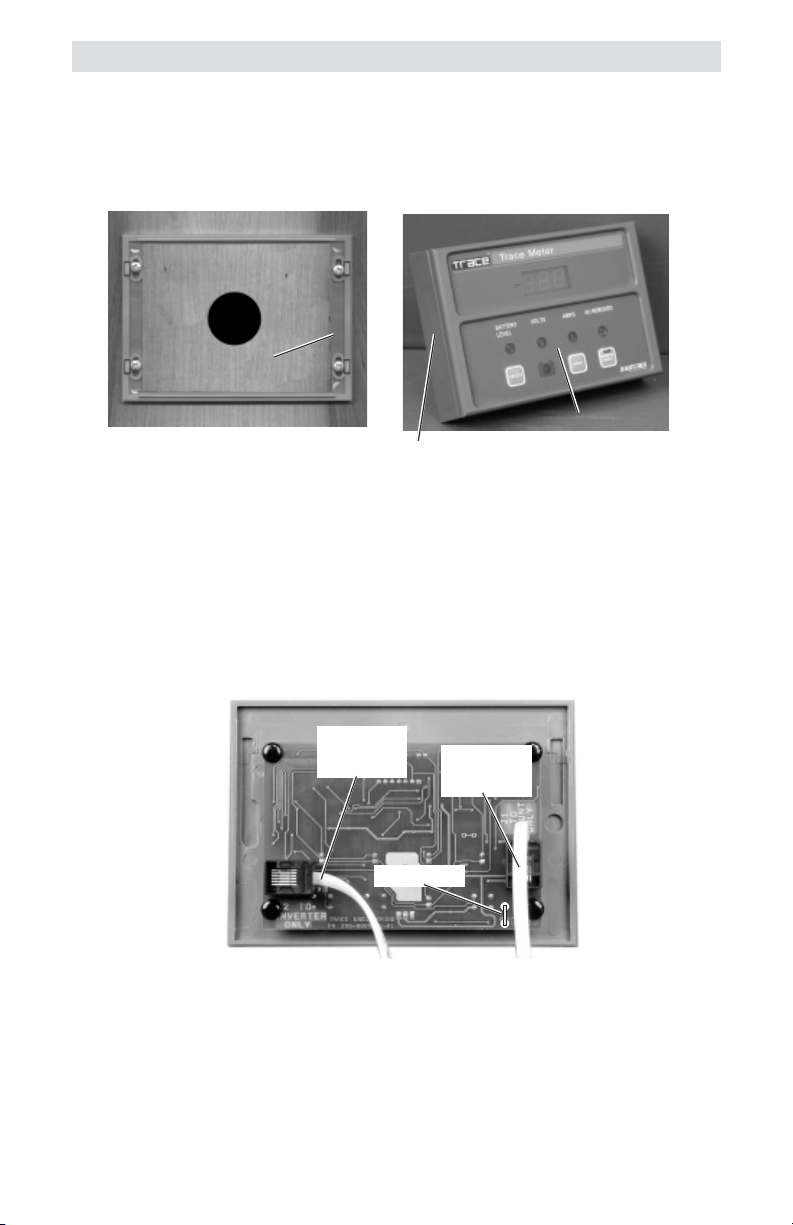
TM500A and Mounting Components
Adaptor
Figure 2-1
Mounting
3
Page 10
2.0 INSTALLATION
Surface Mounting
• Using the mounting bracket as a template, mark the positions for the
screw holes and an area where the cable(s) will feed through.
• Drill out the four screws holes (if required) and wire access opening.
Use a 3/16" bit if the supplied plastic anchors are used. If placing the
screws directly into the backing material, use a 3/32" bit. The wire
access hole should be at least 1/2" diameter to allow the connector to
pass through.
• Mount the bracket using the screws (and anchors if necessary)
supplied. See Figure 2-2. Do not overtighten the screws.
• Install the adaptor onto the bracket by pressing it tightly into place.
• Connect the communications cable (from the shunt) to the “J1 TO
SHUNT ONLY” jack on the TM500A. See Figure 2-3.
• If the TM500A is to function as an ON/OFF remote control for the
inverter, connect the remote control cable (not supplied) to the “J2
INVERTER ONLY” jack. This connector only functions if the inverter
contains a REMOTE jack that allows operation with an RC4 or RC8
remote control.
CAUTION: Do not reverse these cables or the TM500A
circuit board will be permanently damaged.
• Install the meter onto the adaptor by pressing it tightly into place.
4
© 2001 Xantrex Technology Inc.
P/N 973-0012-01-02 Rev. A 05/01
Page 11
Wire
Access
Hole
Trace Meter
Bracket
Trace Meter
Adaptor
2.0 INSTALLATION
Trace Meter
Surface Mounting the TM500A Using the Adaptor
Figure 2-2
J2 TO
INVERTER
ONLY
SPADE LUG
J1 TO
SHUNT
ONLY
Figure 2-3
Communication and Remote Cable Connections
© 2001 Xantrex Technology Inc.
P/N 973-0012-01-02 Rev. A 05/01
5
Page 12
2.0 INSTALLATION
Flush Mounting
To flush mount the TM500A , an opening must be cut in the backing
material to allow room for the circuit board, wires and connectors. Allow at
least one inch depth behind the circuit board for the connectors and wires.
• Use the bracket as a template and mark the positions for the screw
holes. Mark the open area to be cut out for the circuit board.
NOTE: Carefully cut out the circuit board area from the backing
material (i.e., wallboard). Cut inside the lines so there is enough
area left to securely hold the screws.
• Drill out the four screw’s holes (if required) and wire access opening.
Use a 3/16" bit if the supplied plastic anchors are used. If placing the
screws directly into the backing material, use a 3/32" bit.
• Mount the bracket using the screws (and anchors if necessary)
supplied. See Figure 2-4. Do not overtighten the screws.
• Connect the communications cable (from the shunt) to the “J1 TO
SHUNT ONLY” jack (Figure 2-5).
• If the TM500A is to function as an ON/OFF remote control for the
inverter, connect the remote control cable (not supplied) to the “J2
INVERTER ONLY” jack. This connector only functions if the inverter
contains a REMOTE jack that allows operation with an RC4 or RC8
remote control.
CAUTION: Do not reverse these cables or the TM500A circuit
board will be permanently damaged. This is not covered
under warranty.
• Install the meter onto the bracket by pressing it tightly into place.
6
© 2001 Xantrex Technology Inc.
P/N 973-0012-01-02 Rev. A 05/01
Page 13
Area To Be Cut-Out
Trace Meter
Bracket
2.0 INSTALLATION
Trace Meter
Flush Mounting the TM500A
Figure 2-4
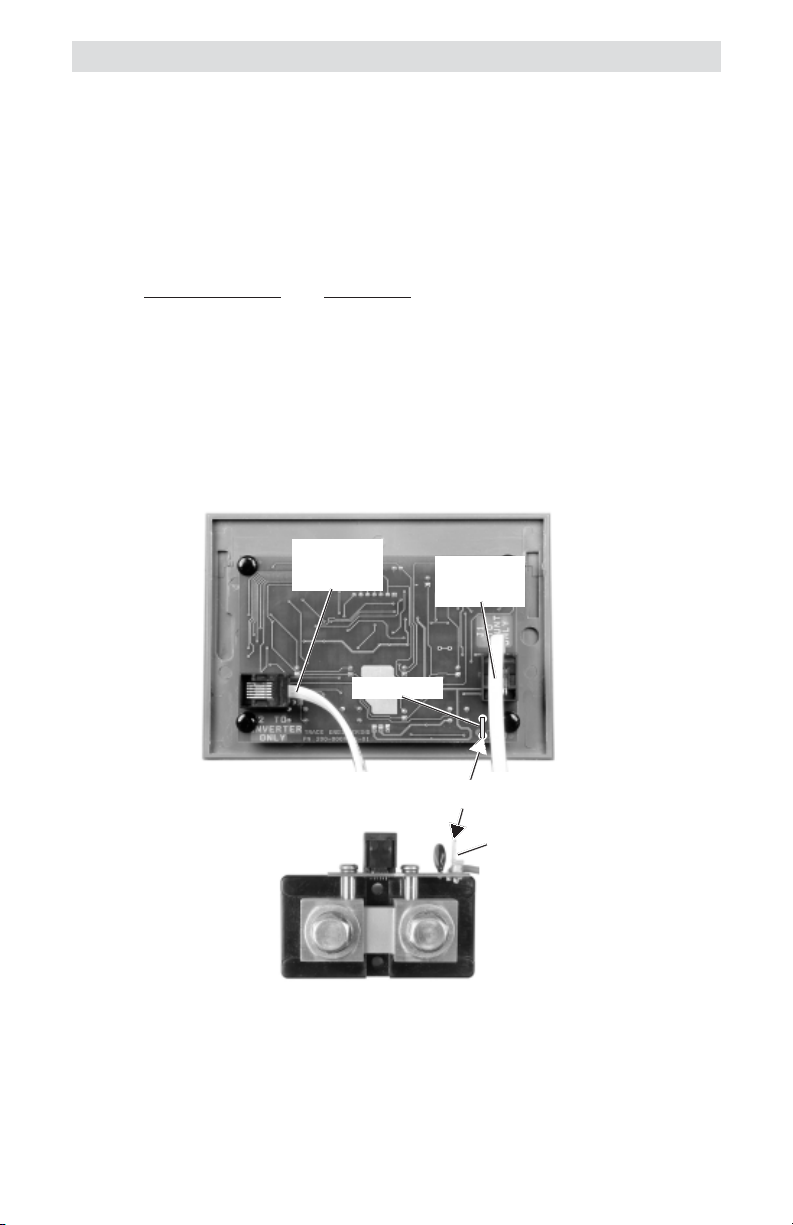
J2 TO
INVERTER
ONLY
SPADE LUG
J1 TO
SHUNT
ONLY
Figure 2-5
Communication and Remote Cable Connections
© 2001 Xantrex Technology Inc.
P/N 973-0012-01-02 Rev. A 05/01
7
Page 14
2.0 INSTALLATION
Extended Length Installations
If the TM500A is mounted in excess of 100 feet from the inverter, an
additional wire (with a spade lugs on both ends) must be connected between
the TM500A and shunt spade lugs. This wire acts as a ground reference and
ensures the meter will read accurately.
Use the following gauge wire for the distance the TM500A is mounted
from the inverter.
Maximum Distance Wire Gauge
250 feet #16 AWG
400 feet #14 AWG
630 feet #12 AWG
1000 feet #10 AWG
J2 TO
INVERTER
ONLY
J1 TO
SHUNT
ONLY
SPADE LUG
Interconnect for distances over
100 feet
SPADE LUG
Figure 2-6
Extended Length Ground Wire
8
© 2001 Xantrex Technology Inc.
P/N 973-0012-01-02 Rev. A 05/01
Page 15

2.0 INSTALLATION
Deltec™ Shunt
WARNING: BEFORE WIRING THE SHUNT TO THE BATTERIES,
SWITCH THE DC DISCONNECT TO OFF AND/OR REMOVE
THE DC FUSE.
Mounting/Wiring the Shunt
The shunt connects between the inverter and batteries in the
negative (–) line (Figure 2-10).
• Mount the shunt on or near the battery enclosure close to the negative
(–) battery terminal. Use appropriate screws to secure the shunt to the
battery enclosure.
• Disconnect the NEGATIVE cable (that connects between the inverter
and battery) from the battery’s negative (–) terminal.
• Connect the free end of the negative cable to the shunt’s terminal
labeled “INVERTER.” Ensure all connections are tight.
• Connect a short length of cable (same gauge) between the battery’s
negative(–) terminal and the shunt’s terminal labeled “BAT MINUS.”
Ensure all connections are tight.
• Connect the cables and hardware to the shunt as shown in Figure 2-7.
NOTE: The cable connection must be flat against the shunt block
with nothing between it for a good connection.
To Battery’s
Negative Terminal
© 2001 Xantrex Technology Inc.
P/N 973-0012-01-02 Rev. A 05/01
Shunt Hex Bolt (9/16 inch head)
Split Lock Washer
Large Washer
Cable Lug
Shunt
Figure 2-7
Shunt Connections
To Inverter’s
Negative Terminal
9
Page 16

2.0 INSTALLATION
Mounting Circuit Board to an Existing Shunt
Model TM500A - NS is supplied without a shunt and is intended to be
wired to an existing shunt. The kit includes two brass 8-32 x 5/8 inch
machine screws, two lock-washers and two metal standoffs.
NOTE: The shunt must be of the proper type (50 mV/500 amps) and
have the necessary threaded screw holes to accommodate the shunt
board.
• Remove the existing two machine screws (if installed) and hardware
from the side of the shunt.
• Install the shunt circuit board and supplied hardware exactly as shown
in Figure 2-8.
NOTE: Use only the hardware supplied in the kit.
10
Brass Screw
Spade Lug
(for extended length installations)
Figure 2-8
Shunt Circuit Board and Hardware
Brass Lock
Washer
Metal Standoff
© 2001 Xantrex Technology Inc.
P/N 973-0012-01-02 Rev. A 05/01
Page 17

2.0 INSTALLATION
Connecting the Shunt Board
• Remove the fuse from the in-line fuse holder by rotating the fuse holder
cap counterclockwise.
• Connect the ring terminal from the fuse holder to the battery’s positive
terminal.
• Connect the shunt communications cable into the RJ11 jack on the shunt
board. This cable can be extended up to 100 feet (30 meters).
• Replace the fuse in the fuse holder. Replace the fuse holder cap by
pushing and rotating it clockwise.
To battery’s
+ -
BATTERY
positive
terminal
SHUNT IN-LINE FUSE
REMOTE JACK
GROUND WIRE
(IF RUN IS OVER
100 FEET)
(Back View)
J2
In-line Fuse
Figure 2-9
In-line Fuse
DC FUSE
DISCONNECT
SHUNT
TRACE
METER
SHUNT WIRE
J1
connector on
TC10, TC25, TC50, TC100
SHUNT JACK
To J 1
back of
meter
INVERTER ON/OFF
REMOTE CABLE
(NOT SUPPLIED)
+
-
INVERTER
INVERTER
RC4/RC8
REMOTE
JACK
3507-00B-F01
© 2001 Xantrex Technology Inc.
P/N 973-0012-01-02 Rev. A 05/01
Figure 2-10
Circuit Diagram
11
Page 18

3.0 CONFIGURATION
Setup
The TM500A is configured at the factory for monitoring a 12 VDC
system. These settings can be changed to meet specific system parameters.
The default settings are:
Charge Efficiency 94 %
%
Voltage (full-charge) 14.4 volts DC
V
Amperage DC 35 amps
A
Ah
Amp Hours 200 Hours
Low-Voltage Indicator 11.2 volts DC
Recharge Reminder OFF
Restoring the Factory Defaults
The factory defaults can be restored to their original settings if desired.
The default values will return to those listed above and are for a 12 VDC
system.
To restore the factory defaults:
1. Set the TM500A into the power saving mode by repeatedly pressing the
SELECT button until the LED display goes blank.
2. Press and hold the RESET button. The display will indicate “ALL”
flashing in the display. Continue to hold the RESET button until the LED
display remains blank.
The factory defaults are now restored.
Step 2 = ALL then blank
ALL
1
Figure 3-1
Resetting to Factory Defaults
12 © 2001 Xantrex Technology Inc.
P/N 973-0012-01-02 Rev. A 05/01
2
Page 19

3.0 CONFIGURATION
Setting Parameters
Individual system parameters can be set by the following procedure:
1. Press the SELECT button until the mode selection indicator to be set is
illuminated.
2. Press the SELECT and RESET buttons simulataniously. Release both
buttons when the LED display flashes.
3. Press and release the RESET button to scroll through the selections (or
values) slowly, or hold the RESET button to scroll rapidly.
4. When the desired value is shown in the LED display, press the SELECT
button to accept it.
Select Value
14.4
1
4
2
Figure 3-2
Setting Parameters
© 2001 Xantrex Technology Inc. 13
P/N 973-0012-01-02 Rev. A 05/01
3
Mode Indicators
Page 20

3.0 CONFIGURATION
Setting Parameters (continued)
Charge Efficiency
Since batteries are not 100 percent efficient, more energy is required to
charge them than can be extracted. Some of this energy is lost in the form of
heat and gassing. An efficiency factor of 94 to 98% is typical for lead-acid
batteries. Consult the battery manufacturer’s specifications for other
battery types.
Set this value to 96% for new batteries and 94% (or lower) for batteries
already in service. The default setting is 94%. Changing this setting affects
the % State-of-Charge meter. The setting range is from 60 to 100%.
%
Setting the Charge Efficiency Factor
If the charge efficiency factor is not known and lead-acid batteries are
used in the system, set the charge efficiency factor to 94%. After the
batteries have been discharged and then fully recharged, the amp-hour
reading should be approximately 000. If this reading is negative when the
CHARGED LED ( ) flashes, increase the efficiency factor. If the numbers
are substantially going above zero before the CHARGED LED flashes,
decrease the efficiency factor. The setting is correct when the CHARGED
LED flashes and the reading is slightly positive.
1. Press the SELECT button until the BATTERY LEVEL LED (%) is
illuminated.
2. Press the SELECT and RESET buttons simulataniously until the LED
display flashes.
3. Press the RESET button to change the displayed efficiency factor.
4. Press the SELECT button to accept the value.
Set Battery Efficiency
% LED Indicates
Efficiency Function
1
4
14 © 2001 Xantrex Technology Inc.
Setting Charger Efficiency
94
2
Figure 3-3
3
Factor in Display
P/N 973-0012-01-02 Rev. A 05/01
Page 21

Setting Parameters (continued)
3.0 CONFIGURATION
Amp Hours
The amp-hour setting should be set to a value equal or lower than the
actual amp-hour capacity of the system’s battery bank. Using a number that
is lower than the actual amp-hour capacity allows the % Battery State-ofCharge meter to provide a more conservative indication for the use of the
batteries to avoid excessively discharging them.
Also note the temperature at which the battery capacity is rated. The
amp-hour capacity of the batteries decreases at temperatures lower than the
rated value.
The amp-hour rating is usually printed on the battery’s label. If the
system contains batteries in parallel, then the amp-hour rating of the parallel
batteries is added together (i.e., two 120 amp-hour rated batteries in parallel
equals 240 amp hours). The amp-hour capacity of a bank does not increase
for series-wired batteries and is equal to the lowest rated battery in the
series string. If the amp-hour capacity is not listed on the battery, consult the
battery manufacturer or dealer for assistance.
Ah
Setting the Amp Hours
1. Press the SELECT button until the AMP-HOURS LED (Ah) is illuminated.
2. Press the SELECT and RESET buttons simulataniously until the LED
display flashes.
3. Press the RESET button to change the displayed amp hours to a value
slightly lower than the system’s total battery amp-hour capacity.
4. Press the SELECT button to accept the new value. The selection range
is between 10 (010.) to 2,550 (2.55) Ah.
NOTE: When the flashing display indicates between 010. to 990.
(decimal point after the right most digit), read the display directly.
When the flashing display indicates between 1.00 to 2.55 (decimal
point two places to the left), multiply the reading by 1000 (i.e., a
flashing 160. equals 160 amp hours; a flashing 1.60 in the display
equals 1,600 amp hours).
© 2001 Xantrex Technology Inc. 15
P/N 973-0012-01-02 Rev. A 05/01
Page 22

3.0 CONFIGURATION
Setting Parameters (continued)
Set Battery Amp-Hour
280.
Rating
Ah LED Indicates
Amp-Hour Function is
Selected
1
2
3
4
Figure 3-4
Setting the Amp Hours
16 © 2001 Xantrex Technology Inc.
P/N 973-0012-01-02 Rev. A 05/01
Page 23

3.0 CONFIGURATION
Setting Parameters (continued)
CHARGED Indicator Setup
The CHARGED indicator LED can be programmed to light when the
batteries are fully charged based on several different parameters:
• Trigger the LED when voltage only parameters are met
• Trigger the LED when voltage and current parameters are met
• Trigger the LED when voltage and time parameters are met
Trigger on Voltage Only
When the TM500A is setup to trigger on voltage only, the CHARGED LED
illuminates when the voltage reaches the level programmed into the TM500A.
NOTE: This mode must be setup first before setting the Voltage and
Current or Voltage and Time modes.
Step A Setting the Fully-Charged Voltage Level
1A. Press the SELECT button until the Voltage LED (V) is illuminated.
2A. Press the SELECT and RESET buttons simulataniously until the LED
display flashes.
3A. Press the RESET button to change the displayed voltage to the
desired fully-charged voltage level:
• For a 12 VDC system, set this voltage between 14.3–14.9 volts for
lead-acid batteries.
• For a 24 VDC system, set this voltage between 28.6–29.6 volts for
lead-acid batteries.
• For a 48 VDC system, set this voltage between 57.2–59.2 volts for
lead-acid batteries.
Refer to the battery manufacturer’s recommendation for other types
of batteries.
4A. Press the SELECT button to accept the new value. The selection
range is between 10 to 64.9 VDC.
5A. Proceed to Step B.
NOTE: In 32–48 VDC systems, whenever a voltage above 35.0 volts
is selected, the display multiplies the actual voltage by 2 for the
TM48 (48 V shunt adapter).
© 2001 Xantrex Technology Inc. 17
P/N 973-0012-01-02 Rev. A 05/01
Page 24

3.0 CONFIGURATION
Setting Parameters (continued)
CHARGED Indicator Setup (continued)
Set Voltage Level
14.4
1A
2A
4A
Setting the CHARGED Indicator Voltage Level
The fully-charged voltage parameters are now set. To allow the voltage
only setting to trigger the fully-charged LED, the amperage setting must be
switched OFF.
Step B Switching OFF the Amperage Detection
1B. Press the SELECT button until the Amperage LED (A) is illuminated.
2B. Press the SELECT and RESET buttons simulataniously until the LED
display flashes.
3B. Press the RESET button until the display indicates OFF.
4B. Press SELECT button to accept.
3A
Figure 3-5
Voltage LED
Illuminates to Indicate
the Voltage Function
is Selected
The TM500A is now setup to trigger the CHARGED indicator LED ( )
when the voltage level equals or exceeds the value programmed in Step A.
When this voltage parameter is met, the CHARGED indicator LED flashes
approximately every four seconds.
NOTE: The CHARGED indicator remains ON (solid) even when the
batteries are discharging, until reset.
Set Amps to
OFF
OFF
1B
Amperage LED
Illuminates to Indicate
the Amperage
Function is Selected
4B
3B
2B
Figure 3-6
Turn Amps OFF for VOLTAGE ONLY Detection
18 © 2001 Xantrex Technology Inc.
P/N 973-0012-01-02 Rev. A 05/01
Page 25

Setting Parameters (continued)
3.0 CONFIGURATION
CHARGED Indicator Setup
(continued)
Trigger on Voltage and Amperage
When this mode is selected, the CHARGED indicator LED illuminates
when the voltage reaches the programmed level (Step A) and the amperage
decreases to the value set in Step B.
As batteries charge, their voltage slowly increases and the charging
current decreases. Setting these parameters allows the CHARGED indicator
LED to illuminate when specified conditions are met. However, if a sufficiently high amperage is being drawn from DC loads during charging, the
meter detects this current, and it prevents the TM500A from illuminating the
CHARGED indicator LED. To set the meter to illuminate the CHARGED LED, the
amperage trigger level must be increased to account for the additional
DC loads.
NOTE: The batteries may not be fully charged if DC loads are in the
system and the current level is increased.
To determine the appropriate fully charged amperage for the system,
divide the battery bank amp-hour capacity by 20. For example; if the battery
bank’s amp-hour rating equals 880 amp hours, divide this value by 20 for an
amperage setting of 44 amps.
Step A Setting the Fully-Charged Voltage Level
1A. Press the SELECT button until the Voltage LED (V) is illuminated.
2A. Press the SELECT and RESET buttons simulataniously until the LED
display flashes.
3A. Press the RESET button to change the displayed voltage to the
desired fully charged voltage level:
• For a 12 VDC system, set this voltage between 14.3–14.9 volts for
lead-acid batteries.
• For a 24 VDC system, set this voltage between 28.6–29.6 volts for
lead-acid batteries.
• For a 48 VDC system, set this voltage between 57.2–59.2 volts for
lead-acid batteries.
Refer to the battery manufacturer’s recommendation for other types
of batteries.
4A. Press the SELECT button to accept the new value. The selection
range is between 10 to 64.9 VDC.
© 2001 Xantrex Technology Inc. 19
P/N 973-0012-01-02 Rev. A 05/01
Page 26

3.0 CONFIGURATION
Setting Parameters (continued)
CHARGED Indicator Setup
1A
(continued)
14.4
Set Voltage Level
Voltage LED
Illuminates to Indicate
the Voltage Function
is Selected
4A
2A
3A
Figure 3-7
Setting the CHARGED Indicator Voltage Level
Step B Setting the Amperage Trigger Level
1B. Press the SELECT button until the Amperage LED (A) is illuminated.
2B. Press the SELECT and RESET buttons simulataniously until the LED
display flashes.
3B. Press the RESET button until the display indicates the desired
amperage.
4B. Press SELECT button to accept.
The selectable amperage values are from 1 to 99 amps.
The TM500A is now setup to trigger the CHARGED indicator LED ( )
when the voltage level equals or exceeds the value programmed in Step A
and the amperage level falls below the value programmed in Step B. When
these parameters are met, the CHARGED indicator LED flashes approximately
every four seconds. Whenever the current goes negative (discharge) the
timer resets to zero. The CHARGED indicator must be manually reset to turn
it OFF.
Set Amperage
1B
44A
Amperage LED
Illuminates to Indicate the
Amperage Function is
4B
2B
3B
Figure 3-8
Trigger on Voltage and Amperage
20 © 2001 Xantrex Technology Inc.
P/N 973-0012-01-02 Rev. A 05/01
Page 27

3.0 CONFIGURATION
Setting Parameters (continued)
CHARGED Indicator Setup (continued)
Trigger on Voltage and Time
When this mode is selected, the CHARGED indicator LED illuminates
when the voltage reaches the programmed level (Step A) and the amperage
remains positive for the specified time (Step B).
Step A Setting the Fully-Charged Voltage Level
1A. Press the SELECT button until the Voltage LED (V) is illuminated.
2A. Press the SELECT and RESET buttons simulataniously until the LED
display flashes.
3A. Press the RESET button to change the displayed voltage to the
desired fully charged voltage level.
• For a 12 VDC system, set this voltage between 14.3–14.9 volts for
lead-acid batteries.
• For a 24 VDC system, set this voltage between 28.6–29.6 volts for
lead-acid batteries.
• For a 48 VDC system, set this voltage between 57.2–59.2 volts for
lead-acid batteries.
Refer to the battery manufacturer’s recommendation for other types
of batteries.
4A. Press the SELECT button to accept the new value.
The selection range is between 10 to 64.9 VDC.
5A. Proceed to Step B.
Set Voltage Level
14.4
1A
4A
2A
3A
Setting the CHARGED Indicator Voltage Level
© 2001 Xantrex Technology Inc. 21
P/N 973-0012-01-02 Rev. A 05/01
Figure 3-9
Voltage LED Illuminates
to Indicate the Voltage
Function is Selected
Page 28
3.0 CONFIGURATION
Setting Parameters (continued)
CHARGED Indicator Setup (continued)
Step B Setting the Time Duration
1B. Press the SELECT button until the Amperage LED (A) is illuminated.
2B. Press the SELECT and RESET buttons simulataniously until the LED
display flashes.
3B. Press the RESET button until the display reaches the hour settings.
These selections are available following the amperage settings.
Select the desired time (in hours or tenths of hours); the voltage must
remain at this level to trigger the CHARGED LED.
4B. Press SELECT button to accept. The selectable amperage values are
from 0.2H to 2.0H (12 minutes to 2 hours).
The TM500A is now setup to trigger the CHARGED indicator LED (
)
when the voltage level equals or exceeds the value programmed in Step A
and the current remains positive for the time duration programmed in Step B.
When these parameters are met, the CHARGED indicator LED flashes
approximately every four seconds. Whenever the current goes negative
(discharging), the timer will reset to zero. The CHARGED indicator LED must
be manually reset to turn it OFF.
Set Time Duration
1. H
1B
Amperage LED
Illuminates to
Indicate the
Amperage
Function is
Selected
4B
2B
3B
Figure 3-10
Trigger on Voltage and Time
22 © 2001 Xantrex Technology Inc.
P/N 973-0012-01-02 Rev. A 05/01
Page 29

3.0 CONFIGURATION
Setting Parameters (continued)
CHARGED Indicator Setup (continued)
Charger Considerations
There are several different types of chargers (relay, taper or threestage) which can affect the settings and prevent the CHARGE LED from
illuminating.
Relay Chargers
Relay type chargers raise the battery to a set voltage level then shut
OFF using only voltage as their parameter. Set the TM500A to the voltage
only mode and set the voltage slightly below the charger turnoff setting.
Taper Chargers
Taper type chargers raise the battery to a specified voltage and shut
OFF when the amperage decreases to a specified level. When using
taper type chargers (pulse-width-modulated), set the voltage and taper
amperage parameters slightly below that of the charger.
If the taper charger is a type that charges up to a certain level and then
waits for a period of time to determine if the batteries are charged, then
set the TM500A to a voltage slightly below the charger’s settings. Set the
time a little shorter than the charger’s time period.
Three-stage Chargers
Three-stage chargers raise the battery to a specified voltage level and
then maintain the batteries at a “Float” voltage and trickle current. Adjust
the TM500A’s voltage parameters slightly below the charger’s float voltage
setting. Set the amperage slightly below the charger’s float amperage
setting.
© 2001 Xantrex Technology Inc. 23
P/N 973-0012-01-02 Rev. A 05/01
Page 30
3.0 CONFIGURATION
Setting Parameters (continued)
Low-Voltage Indicator
The TM500A should be set to trigger on a user specified low DC voltage
level. When the battery voltage falls below this level, the VOLTAGE indicator
V
(
) flashes approximately once every four seconds. This meter is useful to
determine if the batteries are being over-discharged. Refer to the battery
manufacturer’s specifications for the proper low-voltage level.
A voltage between 10 and 35 volts (10 and 64.9 volts for 48-volt
systems) can be specified to activate the low-voltage alarm.
NOTE: Disconnecting the TM500A from the shunt (DC voltage) will
cause this setting to be reset to 0.00. It must be re-configured again
for the proper system low voltage level.
V
Configuring the Low-Voltage Alarm
1. Press and hold the SELECT button until the dSF message is displayed,
then release.
2. Press and release the SELECT button until the bLO message is
displayed in the LED display.
3. Press and release the SELECT and RESET button simultaneously.
NOTE: Pressing the RESET button alone while bLO is displayed will
reset the meter to the current battery voltage.
4. Press the RESET button until the desired voltage level is displayed.
5. Press the SELECT button to accept this value.
6. Press the SELECT button to return to the metering mode.
Step 1 = dSF
Step 2 = bLO
Step 4 = value
dSF
1
2
5
6
Low-Voltage Indicator
24 © 2001 Xantrex Technology Inc.
3
Figure 3-11
4
P/N 973-0012-01-02 Rev. A 05/01
Page 31

4.0 OPERATION
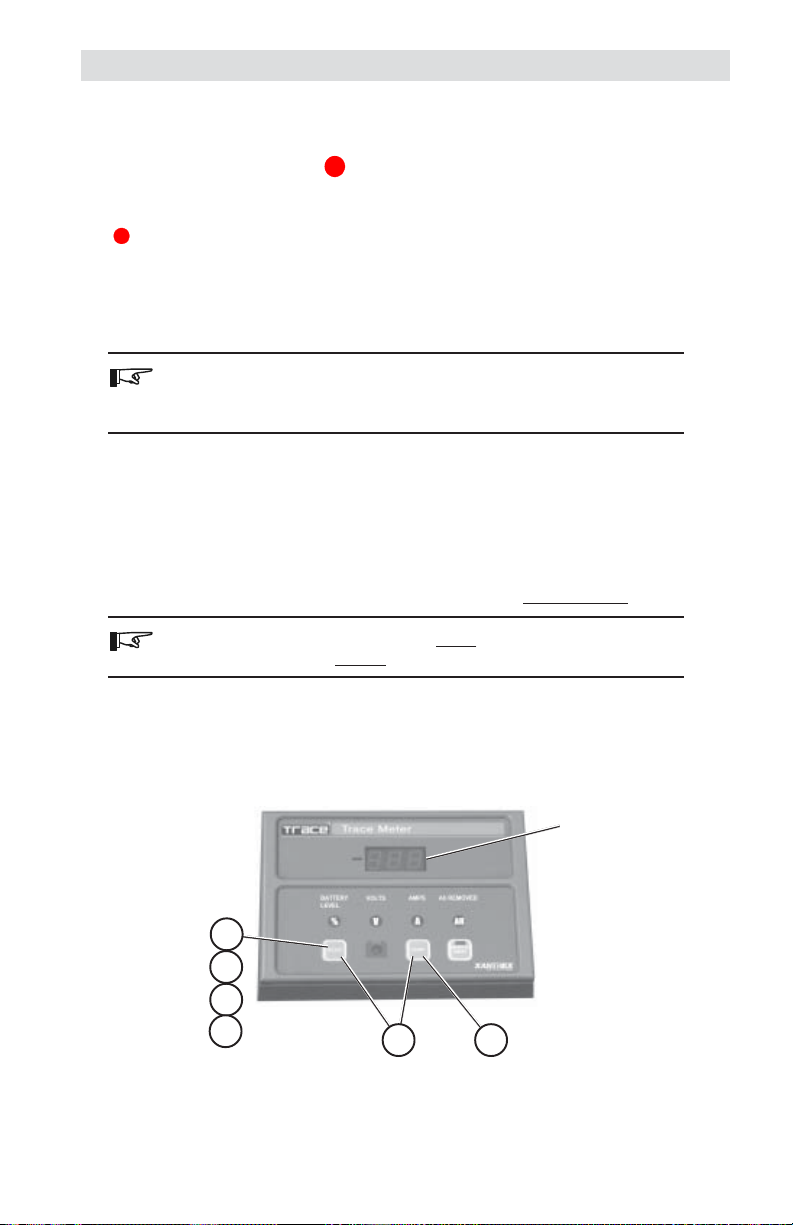
Indicators and Controls
The TM500A contains the following controls and indicators.
• Large three-digit LED display
• Four red mode indicators
• One green CHARGED indicator
• One green INVERTER ON/OFF indicator
• Three pressure sensitive push-buttons
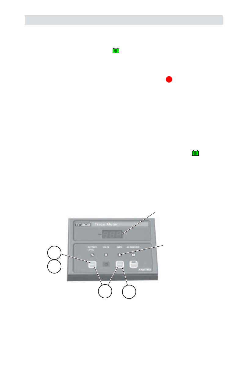
The three-digit LED displays alphanumeric messages with a resolution to
0.00. A negative value (–) indicator is positioned to the left of the display.
Negative
Select
CHARGED
Indicator
Reset Button
3-digit
Display
Mode
Indicators
Inverter Mode LED
(on Button)
Inverter
ON/OFF
Button
Figure 4-1
Front Panel Controls and Indicators
Buttons
SELECT Button
The SELECT button is used to switch the TM500A between the
different meters and modes. One of the LEDs located above the buttons
illuminate, indicating the active function.
RESET Button
The RESET button is used to change the metering parameters and to
reset the CHARGED indicator.
INVERTER ON/OFF Button
The INVERTER ON/OFF button remotely controls the inverter’s ON/
OFF function via the RC4 or RC8 remote control jack. This button
duplicates the function of the inverter’s power switch. The LED
duplicates the indications of the RC8 remote control. Refer to the RC4/
RC8 documentation (supplied with the cable) for LED indications and
modes available (depends on inverter). Remote control cables are
available in 10, 25, 50 and 100 foot lengths. This button/LED does not
function if a remote control cable is not connected or if the inverter does
not support an RC4 or RC8 remote control.
© 2001 Xantrex Technology Inc. 25
P/N 973-0012-01-02 Rev. A 05/01
Page 32

4.0 OPERATION
Indicators and Controls (continued)
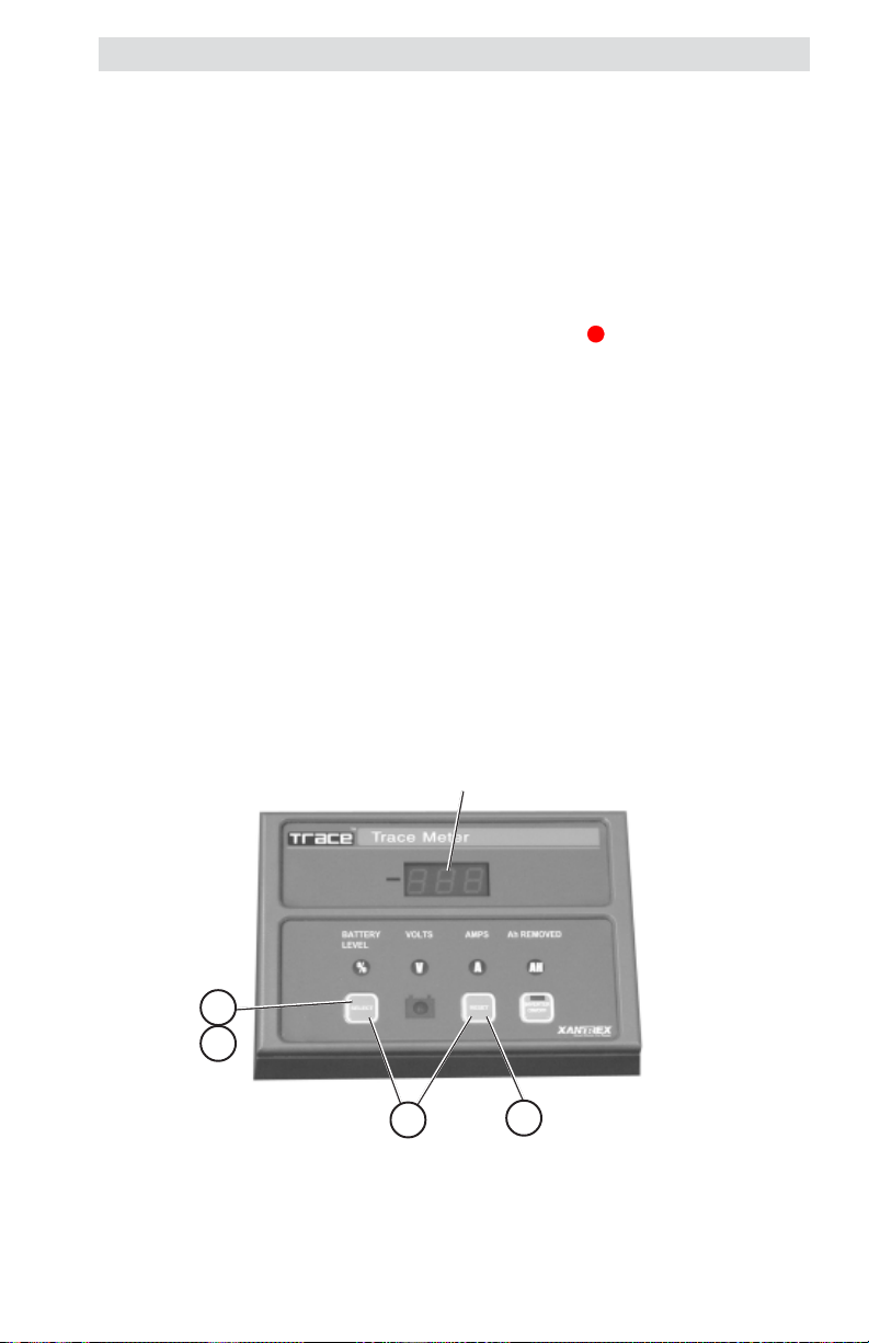
Basic Meters
To display one of the four meters;
• Press the SELECT button until the desired indicator illuminates.
• The LED display indicates the values for the selected function.
Value for selected
Polarity Indicator
mode appears in
the display
12.4
Press SELECT until the
desired function LED
illuminates
Meter Selection and LED Indicators
Figure 4-2
Available Meters
% (state-of charge)
When this indicator is illuminated, the LED display shows the battery’s
state-of-charge based upon the amp-hour reading divided by the amp-hour
capacity of the batteries (or battery bank). The values displayed are:
LO (when battery is below 27.5%)
30 to 90% numerical value (in 5% increments)
FULL when the battery’s state-of-charge is over 92.5% capacity
V (VOLTS)
When this indicator is illuminated, the LED display shows the real time
voltage from 08.0 to 35 volts (for 12- to 24-volt systems) ±0.1 volt accuracy,
or 16.0 to 69.9 volts (for 48-volt systems) ±0.2 volt accuracy.
A (AMPS)
When this indicator is illuminated, the LED display shows the real-time
charge or load current in amps. The range is from ±0.1 to ±999 amps with
a refresh rate of one second. The accuracy is ±1.5%.
26 © 2001 Xantrex Technology Inc.
P/N 973-0012-01-02 Rev. A 05/01
Page 33

4.0 OPERATION
Indicators and Controls (continued)
Ah (AMP HOURS)
When this indicator is illuminated, the LED display shows the total amp
hours used since the last time the amp-hour meter was reset. The range is
from ±0.00 to ±167,000 amp hours. When the decimal point flashes,
multiply the reading by 1000 (i.e., 111. = 111,000). This meter automatically
resets to zero approximately one minute after the CHARGED LED remains
ON solid (stops flashing).
Battery Voltage Indicator
% State-ofCharge Indicator
Amperage Indicator
(Load or Charge)
Amp Hours
(Receiving or
Used) Indicator
Full
Figure 4-3
Mode Indicator LEDs
Power Saving Mode
The TM500A can be put into a low-power/power-saving mode by repeat-
edly pressing the SELECT button until the display goes blank. In this mode,
none of the LED indicators illuminate. The power consumption of the unit is
reduced from 32 mA maximum to approximately 18 mA. Pressing the
SELECT button again exits the power-saving mode.
© 2001 Xantrex Technology Inc. 27
P/N 973-0012-01-02 Rev. A 05/01
Page 34

4.0 OPERATION
Indicators and Controls (continued)
Data Monitors
There are several additional data displays available, accessed by
pressing and holding the SELECT button until “dSF” appears in the display.
Pressing and releasing the SELECT button alternates between its value, then
scrolls to the next menu item.
The available data monitor functions are:
dSF (Days Since Full)
This meter shows the number of days since the batteries were fully
charged. The range on this meter is from 0.00 to 655 days. The value
resets to zero when the battery is recharged (CHARGE LED flashes) or is
manually reset.
cAH (Cumulative Amp Hours)
This meter measures the cumulative amp hours used from the batteries.
This function can be used as a battery life indicator. The range is from 00.0
to 999,000. Multiply the displayed value by 1000 when the decimal point
flashes. The cumulative value remains in memory even if the TM500A is
disconnected. This meter can be manually reset to zero.
bHI (High Battery Voltage)
This meter displays the highest battery voltage detected. Use this meter
to determine if an overvoltage condition occurred or that the charging
sources are charging to the voltage setting of the charger. The meter
resets to the current battery voltage value when it is disconnected and
reconnected to the DC shunt or is manually reset.
bLO (Low Battery Voltage)
This meter displays the lowest battery voltage detected. Use this meter
to determine if the batteries are being over-discharged. This meter resets
to the current battery voltage value when the RESET button is pressed and
must be manually reconfigured after the DC power is cycled or when first
installed.
28 © 2001 Xantrex Technology Inc.
P/N 973-0012-01-02 Rev. A 05/01
Page 35

4.0 OPERATION
Indicators and Controls (continued)
To access the Data Monitor Function:
• Press and hold the SELECT button until dSF appears in the LED display.
The display alternates between the data monitor function and its data.
• Press the RESET button to display the value for the selected function.
• Continue pressing the SELECT button to scroll through all the available
displays and their data.
• When the “bLO” data has been accessed, another press of the SELECT
button returns to the basic meters function.
To reset the data monitor values to zero (or the present value) press and
hold the RESET button for approximately 5 seconds (the data monitor value
flashes three times and then updates).
© 2001 Xantrex Technology Inc. 29
P/N 973-0012-01-02 Rev. A 05/01
Page 36
4.0 OPERATION
Reminders and Indicators
The TM500A features a programmable recharge reminder as well as lowvoltage and charged indicators.
Amp-Hour Reminder
The Amp-Hour LED can be configured to flash at a specified interval
following recharge as a reminder that it is time to charge the batteries. The
range is from 1 to 99 days or it can be turned off. When the number of days
programmed into this counter is exceeded, the Amp-Hour (Ah) LED flashes.
The specified value remains in memory until power is removed from the
TM500A. Recharging the batteries synchronizes the % State-of-Charge and
Amp-hours meters.
To configure this function:
1. Press and hold the SELECT button until the dSF message is displayed
in the LED display, then release the button.
2. Press and release the SELECT and RESET buttons together.
3. Press the RESET button repeatedly until the desired value appears in
the display.
4. Press the SELECT button to accept the value. The range is from 1 to 99
days or OFF.
Step 1 = dSF
Step 3 = value
dSF
1
4
2
Figure 4-4
Meter Selection and LED Indicators
30 © 2001 Xantrex Technology Inc.
3
P/N 973-0012-01-02 Rev. A 05/01
Page 37

4.0 OPERATION
Reminders and Indicators (continued)
Low-Voltage Indicator
A voltage between 10 and 35 volts (10 and 64.9 volts for 48-volt systems)
can be specified to activate the low-voltage alarm. When the battery voltage
falls below this level, the voltage indicator (
every four seconds.
To configure this alarm:
1. Press and hold the SELECT button until the dSF message is displayed,
then release.
2. Press and release the SELECT button until the bLO message is
displayed in the LED display.
3. Press and release the SELECT and RESET button together.
4. Press the RESET button until the desired voltage level is displayed.
5. Press the SELECT button to accept this value.
6. Press the SELECT button to return to the metering mode.
) flashes approximately once
V
Step 1 = dSF
Step 2 = bLO
Step 4 = value
dSF
1
2
5
6
© 2001 Xantrex Technology Inc. 31
P/N 973-0012-01-02 Rev. A 05/01
3
Figure 4-5
Low Voltage Indicator
4
Page 38
4.0 OPERATION
Reminders and Indicators (continued)
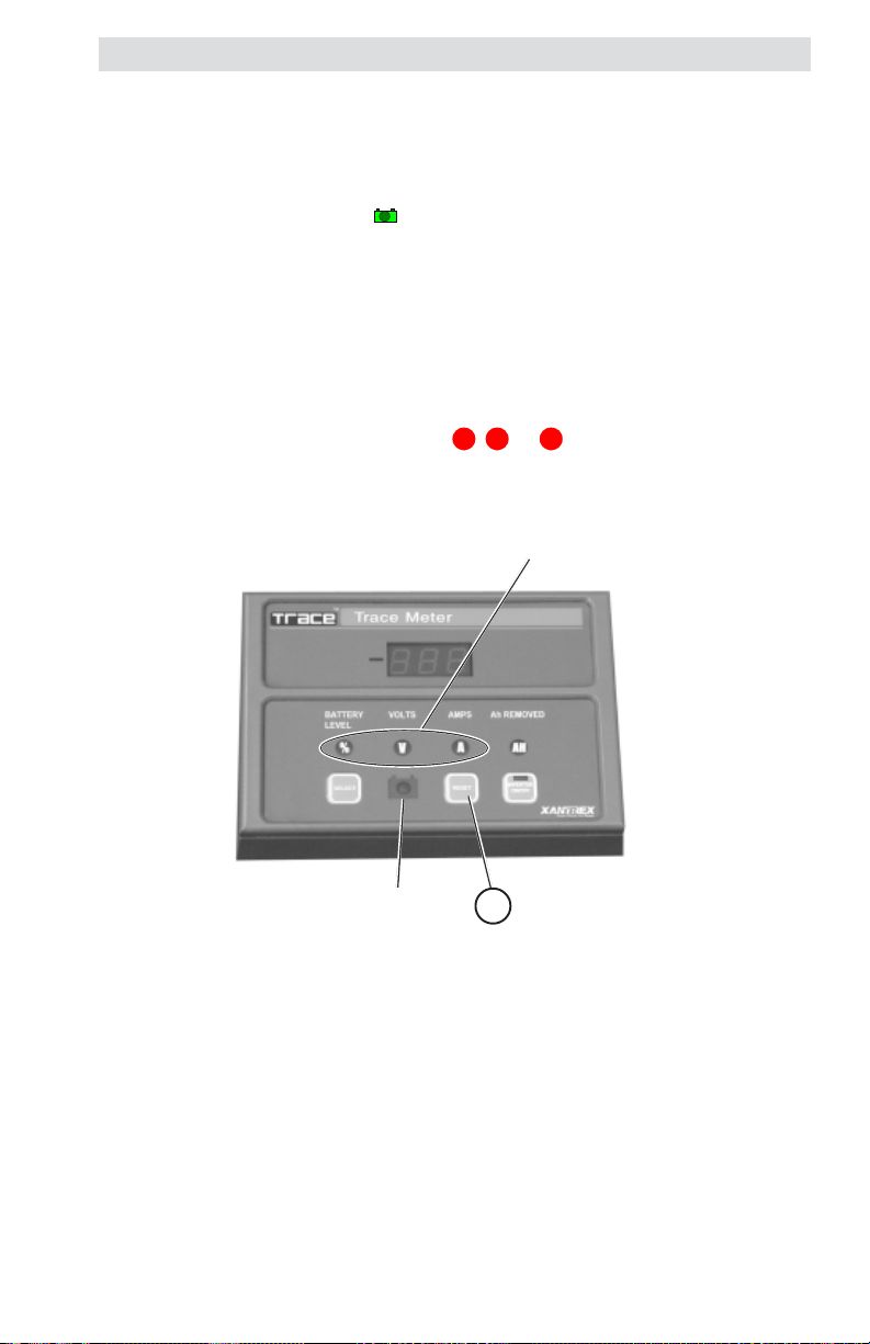
CHARGED Indicator
The CHARGED indicator ( ) can be programmed to flash every four
seconds when specified charging criteria are met. This can be voltage only,
voltage and current, or voltage and time. When the programmed conditions
are met for a minimum of 30 seconds, the CHARGED indicator flashes. The
CHARGED indicator stops flashing and remains ON solid when the “charged”
conditions are no longer met (i.e., the current flow is negative (battery
discharging) continuously for one minute). The Amp-Hour Meter also resets to
zero at this time.
To reset the CHARGED LED:
1. Press the RESET button while the %, V, or A LED is ON.
Reset when any of
these are ON
CHARGED
Indicator LED
Press RESET to reset the
1
CHARGED Indicator
Figure 4-6
Resetting the CHARGED Indicator
32 © 2001 Xantrex Technology Inc.
P/N 973-0012-01-02 Rev. A 05/01
Page 39

5.0 TROUBLESHOOTING
motpmyS esuaCelbissoP noituloS
FFO/NORETREVNIniDEL
.thgiltonseodhctiws
nodeyalpsidegatloV
.tcerroctonsisretem
egrahC-fo-etatSyrettaB
nehw"LLUF"syalpsid
.wolsiegatlov
foegatlovasyalpsidOLb
.0.00
seunitnocDELDEGRAHC
ehthguohtnevehsalfot
evitagensiwolftnerruc
)gnigrahcsidyrettab(
.etunimenorofylsuounitnoc
otnideggulptongulp2J
.retrevniehtroA005MT
aevahtonseodretrevnI
.kcaJelbatapmoc
siegatlovA005MTehT
stlov0.53evobaderugifnoc
.metsystlov-42ro-21arof
siegatlovA005MTehT
stlov0.53wolebderugifnoc
.metsystlov-84arof
.wolootsignittesruoh-pmAotsruohpmaehterugifnoceR
tonsawretemOLbehT
ro,pu-tesgnirudderugifnoc
detcennocsidgniebretfa
.tnuhsehtmorf
YLNOEGATLOV
ehtrofnoitarugifnoc
puteSrotacidnIdegrahC
.woloottesebyam
.kcajlortnoc
,3noitceSees(
.)pu-teSrotacidnI
.)puteSrotacidnI
dnaA005MTotnielbacgulP
etomer8CR/4CRs'retrevnI
lortnocetomerretrevniehT
sledomnosetarepoylno
8CR/4CRnahtiwdeppiuqe
.tupnilortnocetomer
rofA005MTehterugifnoceR
egatlovmetsystcerroceht
degrahC,noitarugifnoC
yrettaB-gnittestcerroceht
,3noitceSees(ezisknab
gnitteS,noitarugifnoC
.)sruoHpmA,sretemaraP
egatloV-woLehterugifnoceR
tcerrocehtrof)OLb(rotacidnI
ees(egatlovyrettab-wol
,noitarugifnoC,3noitceS
-woL,sretemaraPgnitteS
.)rotacidnIegatloV
DEGRAHCehterugifnoceR
etairporppanaotegatlov
arofV6.21,.e.i(eulav
noitceSees(,)metsystlov-21
gnitteS,noitarugifnoC,3
degrahC,sretemaraP
rotacidniDEGRAHCehT
.FFOti
© 2001 Xantrex Technology Inc. 33
P/N 973-0012-01-02 Rev. A 05/01
nrutotteseryllaunamebtsum
A100-D-2100-379
Page 40

6.0 SERVICE INFORMATION
Xantrex Technology Inc., takes great pride in its products and makes
every effort to ensure your unit fully meets your independent powering
needs.
If your product needs repair, contact our Customer Service department
at: (360) 435-8826 to obtain an RMA# and shipping information; or, fax this
page with the following information to: (360) 474-0616. Or contact the
Xantrex Warranty Department at Tracewarranty@traceengineering.com.
Please provide:
Model Number: _________________________________
Serial Number: _________________________________
Purchase Date: _________________________________
Problem: ______________________________________
Include a telephone number where you can be reached during business
hours and a complete return shipping address (P.O. Box numbers are not
acceptable).
Name: __________________________________________
Address: ________________________________________
City: ___________________________________________
State / Province: __________________________________
Zip / Postal Code: _________________________________
Country: ________________________________________
Phone: (____) ____________________________________
FAX: (____) _____________________________________
E-mail Address: ___________________________________
visit our website at: www.xantrex.com
or e-mail us at: xantrex.com
34 © 2001 Xantrex Technology Inc.
P/N 973-0012-01-02 Rev. A 05/01
Page 41

7.0 SPECIFICATIONS
Specifications
Function Range Accuracy
Battery Volts 8.0–35 volts ± 0.1 volt
16.0–70 volts ± 0.2 volt
Battery Amps 0.1–999 amps ± 1.5%
(+ least significant digit)
Battery Amps Resolution
0.1 to 99.9 amps ± 0.1 amp
100 to 999 amps ± 1.0 amp
Battery Level % Low (< 27.5%) ~ 2.5% accuracy
30–90% in 5% increments
FULL (> 92.5%)
Current Draw
Power Saving Mode 18 mA maximum
All other modes 32 mA maximum
Amp Hours -0.00 to ±167,000 amp hours
Battery Capacity 10 to 2550 amp hours
Data Monitoring Functions
dSF–Days Since Full 0.01–655 days
cAH–Cumulative Ah Removed 0–999,000 in nonvolatile memory
bHI–Battery High Volts to 35.1 VDC resettable (12–24 VDC)
to 70.2 VDC (w/optional 48 VDC adaptor)
bLO–Battery Low Volts 8.0 volts, resettable (12–24 VDC)
16.0 volts, resettable (w/48 VDC adaptor)
LED Display 3-digit, 7-segment red LED
with 5 additional indicators
LED Indicators
State of Charge(SOC)/Battery Efficiency
Battery Voltage
Amps
Amp Hours Removed/Battery Capacity
Recharge Reminder (adjustable)
Low Battery Voltage (adjustable)
Dimensions 3-7/8" H x 5-3/8" W x 1-1/4" D
(14 cm H x 9.5 cm W x 3.2 cm D)
Weight approximately 3 lb (1.36 kg)
Mounting
Surface using molded plastic adaptor
Flush using plastic mounting bracket
Specifications @ 25 °C.
Specifications subject to change without notice.
©2001 Xantrex Technology Inc. 35
P/N 973-0012-01-02 Rev. A 05/01
Page 42

8.0 WARRANTY
Limited Warranty
Xantrex Technology Inc., warrants its power products against defects in
materials and workmanship for a period of two (2) years from the date of purchase,
established by proof of purchase or formal warranty registration, and extends this
warranty to all purchasers or owners of the product during the warranty period.
Xantrex does not warrant its products from any and all defects:
y arising out of material or workmanship not provided by Xantrex or
its Authorized Service Centers;
y when the product is installed or exposed to an unsuitable environment as
evidenced by generalized corrosion or biological infestation;
y resulting from abnormal use of the product, alteration, or use in violation of the
instructions;
y in components, parts, or products expressly warranted by another manufacturer.
Xantrex agrees to supply all parts and labor to repair or replace defects
covered by this warranty with parts or products of original or improved design, at
the company's option. Xantrex also reserves the right to improve the design of its
products without obligation to modify or upgrade those previously manufactured.
Defective products must be returned to Xantrex or its Authorized Service Center in
the original packaging or equivalent. The cost of transportation and insurance on
items returned for service is the responsibility of the customer. Return transportation (UPS Ground or equivalent) as well as insurance on all repaired items is paid
by Xantrex.
All remedies and the measure of damages are limited to the above. Xantrex
shall in no event be liable for consequential, incidental, contingent, or special
damages, even if Xantrex has been advised of the possibility of such damages.
Any and all other warranties, expressed or implied, arising by law, course of
dealing, course of performance, usage of trade or otherwise, including, but not
limited to, implied warranties of merchantability and fitness for a particular
purpose, are limited in duration for a period of two (2) years from the original date
of purchase.
Some states or countries do not allow limitations on the term of an implied
warranty, or the exclusion or limitation of incidental or consequential damage,
which means the limitations and exclusions of this warranty may not apply to you.
Even though this warranty gives you specific legal rights, you may also have other
rights which vary from state to state.
5916 - 195th Street N.E., Arlington, WA 98223 Phone: (360) 435-8826 Fax: (360) 435-2229
visit our website at: www.xantrex.com
36 © 2001 Xantrex Technology Inc.
P/N 973-0012-01-02 Rev. A 05/01
Page 43

Page 44

Xantrex Technology Inc.
5916 195th Northeast
Arlington, WA 98223
U.S.A.
t: 360/435.8826
f: 360/435.3945
www.xantrex.com Printed in U.S.A.
© 2001 Xantrex Technology Inc.
P/N 973-0012-01-02 Rev. A 05/01
 Loading...