

Page 1
Smart choice for power
e
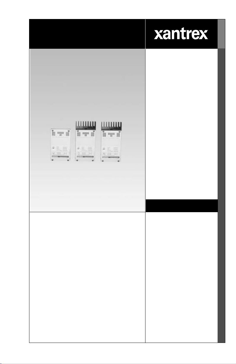
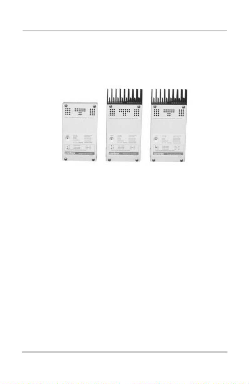
C35
C40
C60
Owner’s Manual
C-Series Multifunction DC Controller
Manual Typ
www.xantrex.com
Page 2

Page 3

C-Series Multifunction
DC Controller
Owner’s Guide
Page 4

About Xantrex
Xantrex Technology Inc. is a world-leading supplier of advanced power
electronics and controls with products from 50 watt mobile units to one MW
utility -scale systems for wind, solar, bat teries, fuel cells, microturbines, and
backup power applica tions in both grid-connected and stand-alone systems.
Xantrex products include inverters, battery chargers, programmable power
supplies, an d variable speed drives that conve rt, supply, control, cl ean, and
distrib u t e el ec tr i cal power.
Trademarks
C-Series Multifunction DC Controller is a trademark of Xantrex International.
Xantrex is a registe red trademark of Xantrex Internat ional.
Other trademarks, registered trademarks, and product names are the property of
their respecti ve owners and are used herein for identification purposes only.
Notice of Copyright
C-Series Mul tif unctio n DC C ontr oll er Own er’s Gui de © No vembe r 200 3 Xantrex
International. All rig hts reserved.
Disclaimer
UNLESS SPECIFICALLY AGREED TO IN WRITING, XANTREX TECHNOLOGY INC.
(“XANTREX”)
(a) MAKES NO WARRANTY AS TO THE ACCURACY, SUFFICIENCY OR SUITABILITY OF
ANY TECHNICAL OR OTHER INFORMATION PROVIDED IN ITS MANUALS OR OTHER
DOCUMENTATION.
(b) ASSUMES NO RESPONSIBILITY OR LIABILITY FOR LOSS OR DAMAGE, WHETHER
DIRECT, INDIRECT, CONSEQUENTIAL OR INCIDENTAL, WHICH MIGHT ARISE OUT OF
THE USE OF SUCH INFORMATION. THE USE OF ANY SUCH INFORMATION WILL BE
ENTIRELY AT THE USER ’S RISK.
Date and Revision
November 2003 Revisi on D
Part Number
975-0004-01-02 Rev D
Contact Information
Telephone: 1 800 670 0707 (toll free North Americ a)
1 360 925 5097 (direct)
Fax: 1 800 994 7828 (toll free North Americ a)
1 360 925 5143 (direct)
Email: customerservice@xantrex.com
Web: www.xantrex.com
Page 5

About This Guide
Purpose
The purpose of this Guide is to provide explanations and
procedures for insta lling, operating, maintai ning, and
troubleshooting the C-Series Multifunction DC Controller.
Scope
This Guide provides safety guidelines, detailed planning and
setup information, procedures for installing the inverter, as
well as information about ope rating and troubleshooting the
unit. It does not provide details about particular brands of
batteries. You need to consult individual battery
manufacturers for this information.
Audience
This Guide is intended for anyone who needs to install and
operate the C-Ser ies Multifunction DC Controller . Installers
should be certified technicians or electricians.
Organization
This Guide is organized into four chapters and three
appendices.
Chapter 1 describes featur es and functions of the C-Series
Multifunction DC Controller.
iii
Page 6

About This Guide
Chapter 2 contains infor mation and procedures to install
C-Series Multifunction DC Controlle r.
Chapter 3 contains infor mation about the operation of a
C-Series Multifunction DC Controlle r.
Chapter 4, “Troubleshooting” contains information about
identifying and resolving possible problems with systems
using a C-Series Multifunc tion DC Controller .
Appendix A, “Specifications” provide the specifications for
the C-Series Multifunc tion DC Controller .
Appendix B, “Batteries” describes types of batteries.
Appendix C, “Diversion Loads” provides additional
information about Diversion Loads.
Conventions Used
The following conventions are used in this guide.
WARNING
Warnings identify conditions that could result in personal injury or
loss of life.
CAUTION
Cautions ide ntify conditions or practices that could result in
damage to the unit or to other equipment.
Important:
an item that you must pay attention to.
iv 975-0004-01-02 Rev D
These notes describe an important action ite m or
Page 7

Abbreviations and Acronyms
ASC Authorized Service Center
BTS Battery Temperature Sensor
CM C-Series Meter
CM/R C-Series Meter - Remote
DC Dir ect Cur rent
LCD Liquid Crystal Displa y
LED Light Emitting Diode
LVD Low Voltage Disconnect
LVR Low Volta g e Reconnect
RE Renewable Energy
Related Information
You can find more information about Xantrex Technology
Inc. as well as its products and servic es at
www.xantrex.com.
About This Guide
975-0004-01-02 Rev D v
Page 8

vi
Page 9

Important Safety Instructions
WARNING
This manual contains important safety instructions that should be
followed during the installa tion and mainten ance of this product . Be
sur e to read, understand, and save these s afety instructions.
General Safety Instructions
• All electrica l work mus t be don e in acco rdan c e wit h
local, national, a nd/or international electr ic al codes.
• Before install ing or using this de vice, read all ins tructions
and cautionary marki ngs located in (or on) this guide , the
controller, the batteries, PV array , a nd any other
equipment used.
• This product is designed for indoor mounting only. Do
not expose this unit to rain, snow or liquids of any type.
In outdoor installa tions, the C-Series controller must be
installed i n a ra inproof enclosu re t o elim inate e xposu re to
rain or water-spray.
• T o reduce t he chance of shor t-cir cuits, use insul ated t ools
when installing or working with the inverter, the
controller, the batteries, or any DC source (e.g., PV,
hydro, or wind).
• Remove all jewelry. This will greatly reduce the chance
of accidental exposur e to liv e circuits.
• The controller contains more than one live circuit
(batteries and PV array, wind, or hydro). Power may be
present at more than one source.
• This product contains no user serviceable parts. Do not
attempt to repair this unit unless fully qualified.
975-0004-01-02 Rev D vii
Page 10

Safety
Battery Safety Information
• Always wear eye protection, such as safety glasses, when
working with batteries.
• Remove all jewelry befor e working with ba tteries.
• Never work alone. Have someone assist you with the
installation or be close enough to come to your aid when
working with batteries.
• Always use proper lifting techniques when handling
batteries.
• Always use iden ti cal typ es of ba tter ie s.
• Never install old or unt ested batteries. Check each
battery’s date code or label to ensure age and type.
• Batteries shou ld be installed in a well-vented area to
prevent the possible buildup of explosive gasses. If the
batteries ar e installe d ins ide an enclosu re, vent its h ighest
point to the outdoors.
• When installing bat teries, allow at least 1 inch of air
space between batteries to promote cooling and
ventilation.
• NEVER smoke in the vicinity of a battery or generator.
• Always connect the batteries first, then connect the
cables to the inverter or controller. This will greatly
reduce the chance of spark in the vicinity of the batteries.
• Use insulated tool s when working with batteries.
• When connecting batteries, always verify proper voltage
and polarity.
• Do not short-circu it battery cables. Fire or explosion can
occur.
• In the event of exposure to battery electrolyte, wash the
area with soap and water. If acid enters the eyes, flood
them with running cold water for at least 15 minutes and
get immediate medical atte ntion.
• Always recycle old batteries. Contact your local
recycling cen ter fo r p rop er disp o sal info rm at ion.
viii 975-0004-01-02 Rev D
Page 11

Battery Safety Information
CAUTION:
A battery can produce the following hazards to personal safety:
• electrical shock,
• burn from high-short-ci rcuit current, and/or
• fire or explosion from ve nted gasses.
Observe proper prec autions when working with or around batteries.
975-0004-01-02 Rev D ix
Page 12

x
Page 13

Contents
Important Safety Instructions
1
Introduction
Features - - - - - - - - - - - - - - - - - - - - - - - - - - - - - - - - - - - - - - - 2
Operating Modes - - - - - - - - - - - - - - - - - - - - - - - - - - - - - - - - - 3
Charge Control Mode - - - - - - - - - - - - - - - - - - - - - - - - - - - 4
Three-S tag e Bat tery Ch ar g ing - - - - - - - - - - - - - - - - - - - 4
Battery Temperature Compensation - - - - - - - - - - - - - - - 6
Manual or Auto Equalization Charge - - - - - - - - - - - - - - 6
Load Control Mode- - - - - - - - - - - - - - - - - - - - - - - - - - - - - 6
Controller Functions - - - - - - - - - - - - - - - - - - - - - - - - - - - - - - - 7
Photovoltaic Charge Controller - - - - - - - - - - - - - - - - - - - - - 7
Automatic PV Array Night Disconnect- - - - - - - - - - - - - 8
Diversion Controller - - - - - - - - - - - - - - - - - - - - - - - - - - - - 8
Diversion Loads - - - - - - - - - - - - - - - - - - - - - - - - - - - - 9
Load Controller - - - - - - - - - - - - - - - - - - - - - - - - - - - - - - 10
Low Voltage Disconnect - - - - - - - - - - - - - - - - - - - - - 11
Low Voltage Reconnect- - - - - - - - - - - - - - - - - - - - - - 11
Optional Accessories - - - - - - - - - - - - - - - - - - - - - - - - - - - - - 12
- - - - - - - - - - - - - - - - - - v ii
2
Installation
Pre-Installation - - - - - - - - - - - - - - - - - - - - - - - - - - - - - - - - - 14
Removing the Top Cover - - - - - - - - - - - - - - - - - - - - - - - - 14
Removing Knockouts - - - - - - - - - - - - - - - - - - - - - - - - - - 14
Mounting the Controller - - - - - - - - - - - - - - - - - - - - - - - - 16
Configuring the C-Series Controller - - - - - - - - - - - - - - - - - - - 18
Jumper Settings - - - - - - - - - - - - - - - - - - - - - - - - - - - - - - 18
Operating Mode Jumper- - - - - - - - - - - - - - - - - - - - - - 20
Voltage Jumper- - - - - - - - - - - - - - - - - - - - - - - - - - - - 20
xi
Page 14

Contents
Automatic/Manual Battery Equalization (EQ) and Low
Voltage Reconnect (LVR) Jumper- - - - - - - - - - - - - - 21
Adjusting the C-Series Volta ge Settings- - - - - - - - - - - - - - - - - 22
Setting Voltage Parameters for Charge Control Mode- - - - - 22
Setting Voltage Parameters for Load Control Mode - - - - - - 24
Setting Voltage Parameters Diversion Control Mode - - - - - 26
Setting Voltage Parameters for Alkaline Batteries - - - - - - - 26
Using a Digital Voltmeter to Adjus t Voltage Settings- - - - - 28
Equalization Charging- - - - - - - - - - - - - - - - - - - - - - - - - - - - - 30
Manual Equalization - - - - - - - - - - - - - - - - - - - - - - - - - - - 31
Automatic Equalization - - - - - - - - - - - - - - - - - - - - - - - - - 32
Terminat ing the E q ual izat i on Process - - - - - - - - - - - - - - - 33
Temperature Compensation - - - - - - - - - - - - - - - - - - - - - - - - - 33
Temperature Compensation Base d on Battery Type - - - - - - 34
Automatic Battery Temperature Compensation - - - - - - - - - 34
Manual Battery Temperature Compensation - - - - - - - - - - - 36
Grounding- - - - - - - - - - - - - - - - - - - - - - - - - - - - - - - - - - - - - 37
Wiring - - - - - - - - - - - - - - - - - - - - - - - - - - - - - - - - - - - - - - - 38
DC Terminal Connector Locations - - - - - - - - - - - - - - - - - 38
Terminal Torque Requirements- - - - - - - - - - - - - - - - - 39
Wire Size and Over-current Prote c tion Requirements- - - - - 39
Current Rating - - - - - - - - - - - - - - - - - - - - - - - - - - - - 39
Minimum Recommended Wire Gauge - - - - - - - - - - - - 40
Surge Protection - - - - - - - - - - - - - - - - - - - - - - - - - - - 40
Over-current Protection - - - - - - - - - - - - - - - - - - - - - - 41
Long-distance wire runs- - - - - - - - - - - - - - - - - - - - - - 42
Maxim um O n e-way D istan c e an d Wire Size - - - - - - - - 42
PV Charge Control Mode Wiring - - - - - - - - - - - - - - - - - - 44
Diversion Control Mode Wiring - - - - - - - - - - - - - - - - - - - 46
DC Load Con trol Mo d e Wi rin g- - - - - - - - - - - - - - - - - - - - 48
Installing Optional Accessories- - - - - - - - - - - - - - - - - - - - - - - 50
Installing a Digital Display- - - - - - - - - - - - - - - - - - - - - - - 50
Installing the Battery Temperature Sensor - - - - - - - - - - - - 51
Reinstalling the Faceplate - - - - - - - - - - - - - - - - - - - - - - - - - - 52
xii 975-0004-01-02 Rev D
Page 15

3
Operation
Basic Operation - - - - - - - - - - - - - - - - - - - - - - - - - - - - - - - - - 54
LED Status Indicator - - - - - - - - - - - - - - - - - - - - - - - - - - - - - 55
Charge Control or Diversion Control Indications (Green) - - 56
Blinking Green - - - - - - - - - - - - - - - - - - - - - - - - - - - - 57
Solid Green - - - - - - - - - - - - - - - - - - - - - - - - - - - - - - 57
Equalization Mode Indication (Red/green) - - - - - - - - - 58
Load Control Indications (Red)- - - - - - - - - - - - - - - - - - - - 58
Blinking Red - - - - - - - - - - - - - - - - - - - - - - - - - - - - - 58
Solid Red- - - - - - - - - - - - - - - - - - - - - - - - - - - - - - - - 58
Error Mode Indication (Orange) - - - - - - - - - - - - - - - - - - - 59
Over-temperature Condition - - - - - - - - - - - - - - - - - - - 59
Over-Current Condition- - - - - - - - - - - - - - - - - - - - - - 59
Low-voltage Disconnect Condition - - - - - - - - - - - - - - 60
Reconnecting to Loads - - - - - - - - - - - - - - - - - - - - - - - - - - - - 60
Reset Switch - - - - - - - - - - - - - - - - - - - - - - - - - - - - - - - - - - - 61
4
Troubleshooting
PV Charge Control Troubleshooting - - - - - - - - - - - - - - - - - - - 64
Diversion Control Trouble shooting - - - - - - - - - - - - - - - - - - - - 66
Load Control Troubleshooting - - - - - - - - - - - - - - - - - - - - - - - 68
Contents
A
Specifications
Electrical Specifications - - - - - - - - - - - - - - - - - - - - - - - - - - - 70
Features and Options Specifications - - - - - - - - - - - - - - - - - - - 71
Environmental Specifications - - - - - - - - - - - - - - - - - - - - - - - - 72
B
Batteries
Battery Types - - - - - - - - - - - - - - - - - - - - - - - - - - - - - - - - - - 74
Automotive Batteries- - - - - - - - - - - - - - - - - - - - - - - - - - - 74
Maintenance-Free Batteries - - - - - - - - - - - - - - - - - - - - - - 74
Deep-Cycle Batteries- - - - - - - - - - - - - - - - - - - - - - - - - - - 74
Sealed Batteries - - - - - - - - - - - - - - - - - - - - - - - - - - - - - - 75
NiCad and NiFe Batteries - - - - - - - - - - - - - - - - - - - - - - - 76
975-0004-01-02 Rev D xiii
Page 16

Contents
Battery Sizing - - - - - - - - - - - - - - - - - - - - - - - - - - - - - - - - - - 76
Equalization Charging- - - - - - - - - - - - - - - - - - - - - - - - - - - - - 77
Equalization Setpoints (Non-Sealed Batteries Only)- - - - - - 79
C
Diversion Loads
Diversion Load Types- - - - - - - - - - - - - - - - - - - - - - - - - - - - - 82
Warranty and Product Information
Warranty - - - - - - - - - - - - - - - - - - - - - - - - - - - - - - - - - - - - - 85
Disclaimer - - - - - - - - - - - - - - - - - - - - - - - - - - - - - - - - - - - - 86
Return Material Authorization Policy - - - - - - - - - - - - - - - - - - 87
Return Procedure - - - - - - - - - - - - - - - - - - - - - - - - - - - - - - - - 88
Out of Warranty Service - - - - - - - - - - - - - - - - - - - - - - - - - - - 88
Information About Your Syste m - - - - - - - - - - - - - - - - - - - - - 89
Index
xiv 975-0004-01-02 Rev D
- - - - - - - - - - - - - - - - - - - - - - - - - - - - - - - - - - - - - - - - - - 91
Page 17

Figures
Figure 1-1 C-Series Multifunction DC Charge Controllers - - - - - - 2
Figure 1-2 3-stage Battery Charging Process - - - - - - - - - - - - - - - 5
Figure 1-3 PV Charge Controller - - - - - - - - - - - - - - - - - - - - - - - 7
Figure 1-4 Diversion Controller - - - - - - - - - - - - - - - - - - - - - - - - 9
Figure 1-5 Load Controller - - - - - - - - - - - - - - - - - - - - - - - - - - 11
Figure 1-6 Decal Displaying Load Control Voltage Settings - - - - 12
Figure 1-7 Optional Accessories - C M/R, CM, and BTS- - - - - - - 12
Figure 2-1 Removing the Front Cover - - - - - - - - - - - - - - - - - - - 14
Figure 2-2 C-Series Dimensions and Knoc kout Locations
(Not to Scale)- - - - - - - - - - - - - - - - - - - - - - - - - - - - 15
Figure 2-3 Mounting the C-Series Multifunction DC Controller - 17
Figure 2-4 Jumper Positions- - - - - - - - - - - - - - - - - - - - - - - - - - 18
Figure 2-5 Ci rc uit Board Co m po ne nts - - - - - - - - - - - - - - - - - - - 19
Figure 2-6 Mode of Operation Jumper- - - - - - - - - - - - - - - - - - - 20
Figure 2-7 Voltage Selection Jumper- - - - - - - - - - - - - - - - - - - - 20
Figure 2-8 EQ/LVR Jumper and Reset Switch - - - - - - - - - - - - - 21
Figure 2-9 Bulk and Float Charge Pote ntiometers (pots)- - - - - - - 22
Figure 2-10 Bulk and Float Charge Settings for Charge/Div ersion
Control Mode- - - - - - - - - - - - - - - - - - - - - - - - - - - - 23
Figure 2-11 Potentiometers with Decal for LVR and LVD Settings 24
Figure 2-12 LVR and LVD Settings for Load Control Mode- - - - - 25
Figure 2-13 R46 Resistor Location - - - - - - - - - - - - - - - - - - - - - - 26
Figure 2-14 Voltage Settings with R46 Resistor Clipped - - - - - - - 27
Figure 2-15 Test Points for Adjusting Voltage Using a DVM - - - - 29
Figure 2-16 Manual Equalization Settings - - - - - - - - - - - - - - - - - 30
Figure 2-17 Front Panel LED and Reset Switch Location- - - - - - - 31
Figure 2-18 Auto Equalization Settings- - - - - - - - - - - - - - - - - - - 32
Figure 2-19 Terminating the E qu al izat i on Charge - - - - - - - - - - - - 33
Figure 2-20 Grounding the C-Series Chassis - - - - - - - - - - - - - - - 37
Figure 2-21 DC Connection Terminals - - - - - - - - - - - - - - - - - - - 39
xv
Page 18

Figures
Figure 2-22 AWG Wire Gauge Reference Chart - - - - - - - - - - - - - 40
Figure 2-23 PV Charge Control Mode Wiring - - - - - - - - - - - - - - 45
Figure 2-24 Diversion Control Mode Wiring - - - - - - - - - - - - - - - 47
Figure 2-25 Load Control Mo d e Wi ri ng - - - - - - - - - - - - - - - - - - 49
Figure 2-26 Installing a Dig ital D isp lay- - - - - - - - - - - - - - - - - - - 50
Figure 2-27 Installing the BTS- - - - - - - - - - - - - - - - - - - - - - - - - 51
Figure 2-28 Re-installing the CM Faceplate- - - - - - - - - - - - - - - - 52
Figure 3-1 C-Series Status LED and Reset Button Location - - - - 54
Figure 3-2 C- Series Front Pane l Lab el- - - - - - - - - - - - - - - - - - - 55
Figure 3-3 Reset Switch - - - - - - - - - - - - - - - - - - - - - - - - - - - - 61
xvi 975-0004-01-02 Rev D
Page 19

Tables
Table 2-1 Factory Def aul t Se ttin g s for C-S eri es Co nt ro lle rs- - - - 19
Table 2-2 Variances in Charging Voltage based on
Battery Temperature - - - - - - - - - - - - - - - - - - - - - - - 35
Table 2-3 Minimum Wire Size - - - - - - - - - - - - - - - - - - - - - - - 41
Table 2-4 One-Way Wire Distance and Wire Size - - - - - - - - - - 43
Table 3-1 Battery Voltage LED Indicators - - - - - - - - - - - - - - - 56
Table 4-1 PV Charge Control Problems - - - - - - - - - - - - - - - - - 64
Table 4-2 Diversion Control Problems - - - - - - - - - - - - - - - - - - 66
Table 4-3 Load Control Problems - - - - - - - - - - - - - - - - - - - - - 68
Table A-1 Electrical Specifications- - - - - - - - - - - - - - - - - - - - - 70
Table A-2 Features and Options Specifications- - - - - - - - - - - - - 71
Table A-3 Environmental Specifications - - - - - - - - - - - - - - - - - 72
Table B-1 Typical Bulk and Float Setpoints for Batteries- - - - - - 79
Table C-1 Power Dissipation- - - - - - - - - - - - - - - - - - - - - - - - - 82
xvii
Page 20

xviii
Page 21

1
Chapter 1 describes features and functions of the
C-Series Multifunction DC Controller.
For information on: See:
“Features” page 2
“Operating Modes” page 3
“Controller Functions” page 7
“Optional Accessories” page 12
Introduction
Page 22
Introduction
Features
The C35/C40/C60 (C-Series) controllers can be used with
12-volt, 24-volt, or 48-volt DC systems (depending upon
model) as Charge Controller or a Load Controller.
C35
Figure 1-1
C40
C-Series Multifunction DC Charge Controllers
C60
Numerous features are provi ded standard to maximize the
performance of th e system:
• Solid-state Pulse Width Modulated (PWM) charging
process with thre e-st ag e con tr ol, temp era tur e
compensation, and manual or automatic equalization to
maximize system performance and increase battery life.
• Multi color LED with easy to read mode/status label.
• Electronic overload and short-circuit protection with
automatic and manual reset capability increases the
reliability of unattended systems by eliminating blown
fuses and tripped circu it brea kers.
• Adjustment of charge setpoints is provided by rotary
controls (potentiometers) with removable knobs.
Calibrated scales and test points allow precise
adjustments of settings.
• Over-temperature protection for the electronic circuitry
when used in hot environments (over 113 °F/45 °C).
2 975-0004-01-02 Rev D
Page 23

• Indoor-type, powder-coated enclosure, for wall
mounting.
• Conformal-coated circuit boards, plated terminals,
powder-coate d metal components, and stainless steel
fasteners improves tolerance to hostile environments.
• Meets National Elect rical Code (NEC) and other
internation al co ntr o ller speci fications.
• The C35, C40 a nd C60 models are UL listed to the
U.S. UL Standard 1741 (1s t edition), and Canada
(CSA-C22.2 No. 107.1-95).
• 2-year limited warr an ty.
Operating Modes
The DC controller is a critical component in any solar, wind
or hydro power generation syst em and protects the batteries
from over-di scharge and over-charge conditions. The
C-Series has two operating modes (Charge Control mode and
Load Control mode determined by the Operat ing mode
jumper (See Figure 2-5). These two different operating
modes allow the C-Series to be instal led and f unction a s thr ee
different DC contr ollers.
• Cha rge Control Mode
• PV Charge Controller - contr ols charging in PV
installations.
• Diversion Controller – used in PV, wind, or hydro
installations to divert any excess energy to a diversion
load and in the case of a wind or hydro generator, helps
to prevent over-spin damage.
Operating Modes
• Load Control Mode
• Load Contr oller - prevents damage to the battery from
over-disc harge during periods of poor char ging or
excessive loa ds.
975-0004-01-02 Rev D 3
Page 24

Introduction
Important:
than one function at the same time. If several functions ar e
requi r e d in a syst em, a dedi cated c ontroller must be used for each
function.
The C-Series controller cannot operate in more
Charge Control Mode
In the Charge Control mode, the C-Series controls how the
batteries are char ged by the DC source (solar , wind, or
hydro). It us es a 3-stage char ging protocol t o maint ain ba tter y
voltage at bulk and/or float le vels.
When charging, the C-Series controller monitors the ba tt eries
and depending on how it is wired wil l regu late the PV c urrent
(as a PV Charge Controller) or divert e xcess energy from PV,
hydro, or wind to a DC load (as a Diversion Controller) and
allows the battery to charge according to user-defined
settings based on the amount of DC power available .
When the C-Series operates in the Charge Control mode, it
provides:
• three-sta ge charging of battery voltag e,
• automatic temperature compensation (if the BTS is used),
and
• automatic or manual equalization charging.
Three-Stage Battery Charging
The three-stage charging process results in faster charging
compared to on-off relay type or constant voltage solid-state
regulators. Faster recharging increases the performance of the
system by storing more of the PV array’s limited output. The
final float voltage setting reduces battery gassin g, mini mize s
watering requirements and ensures complete battery
recharging. The C-Series will use this protocol in either PV
Charge Control mode or in Diversion Control mode. It does
not charge the batteries when in Load Control mode. Battery
voltage and current vary dur ing the three-stage charging
process as follows.
4 975-0004-01-02 Rev D
Page 25

Bulk Stage
During this stage, the batteries are charged at the bulk voltage
setting and maximum current output of the DC sourc e. When
the battery voltage reaches the bulk voltage setting, the
controller acti vates the next stage (absorption).
Absorption Stage
During this stage, the volta ge of the batte ry is held a t the bulk
voltage setting until an internal timer has accumulated one
hour. Current gradually decline s as the battery capacity is
reached.
Float Stage
During this sta ge, the vol tage of t he batt ery i s held at the floa t
voltage setting. Full current can be provided to the loads
connected to the battery during the float stage from the PV
array. When battery voltage drops below the float setting for
a cumulative period of one hour, a new bulk cycle will be
triggered.
Operating Modes
Charging
Started
DC Voltage
0 volts
DC Current
0 amps
Time
Figure 1-2
Bulk Stage
Increasing Voltage Constant Voltage Reduced Vol tage
Max Amps
Constant Current Reducing Current Reduced Current
3-stage Battery Charging Process
Absorption Stage
Bulk Volts Setting
Absorption Time
Float Stage
Float Volts Setting
975-0004-01-02 Rev D 5
Page 26

Introduction
Battery Temperature Compensation
The optional Battery Temperature Sensor (BTS)
automatically adj usts the charging process of the C-Series
controller. With the BT S in stalled, th e C-Series will increase
or decrease the battery charging voltage depending on the
temperature of the batt ery to optim ize the charge to the
battery and maintain optimal performance of the battery.
If not using the BTS, the voltage settings for charging will
need to be adjusted based on the temperatur e of the
environment around the batteries and on the type of batteries
being used.
See “T e mperature Compensation” on page 33 for information
on how to set the voltage.
Manual or Auto Equalization Charge
The C-Series controller can be used to manually or
automatically pro vide the battery bank with an equalize
charge. Factory default setting is for MANUAL Equalization
charging. Be sure to be familiar with all the cautions and
warnings concerning equalization charging batteries or
damage to batteries can occur.
Load Control Mode
In the Load Control mode, the C-Series controls when to
remove a loa d or loads from the system when an
over-disc harge or over-l oad situation occurs. The C-Series
controller uses the user-adjustable setpoints to determine
when to connect or reconnect loads depending on battery
voltage. A load controller prevents damage to the battery
from over-di scharge during periods of poor weather or
excessive loa ds. The u nit does not charge the batteri es when
in this function.
6 975-0004-01-02 Rev D
Page 27

Controller Functions
The C-Series can be configured to function as three different
controllers:
• PV Charge Controller (Charge Control mode)
• Diversion Controller (Charge Control mode)
• Load Controller (Load Control m ode)
Photovoltaic Charge Controller
The C-Series cont roller can operate as a Photovoltaic Charge
Controller, also called a “series regulator” . De pending on the
model, the controller can regulate up to 60 amps of
continuous photovolta ic (PV) array current at 12 or 24 volts
(C60 or C35 mode ls), or 12-, 24- or 48-volts DC (C40 model)
for charging bat teries. This rating includes the NEC required
derating.
Controller Functions
Figure 1-3
975-0004-01-02 Rev D 7
PV Charge Controller
If the PV array’s output increases above the rated amp level
due to reflecti on or “edge of cloud effect,” the controller will
continue to operate until the heatsink reaches a maximum
safe operating temper ature. This will take several minutes to
occur, depending upon the ambient temperatur e involved.
When the heats in k re aches the max imu m saf e tem perature,
the controller will reduc e the current, cooling the transis tors
and the heatsink.
Page 28

Introduction
If the current from the PV array reaches 85 amps, the
controller will turn off to protect the circuitry. In the event of
a shutdown, the controller automatically resets itself after
10 minutes (if overcurrent condition is no longer present).
See “Operating Mode Ju mper” on page 20 for information on
configuring this function.
Automatic PV Array Night Disconnect
When using PV Charge Control mode, the PV array is
automatically disc onnected from the battery at night to
prevent reverse leakage of power. This eliminates the need
for a blocking diode between the bat tery a nd the PV array. If
thin-film or amorphous sola r modules are being used, diodes
may still be required to prevent damage from partial shading
conditions.
Check the documentation provide d with the PV modules.
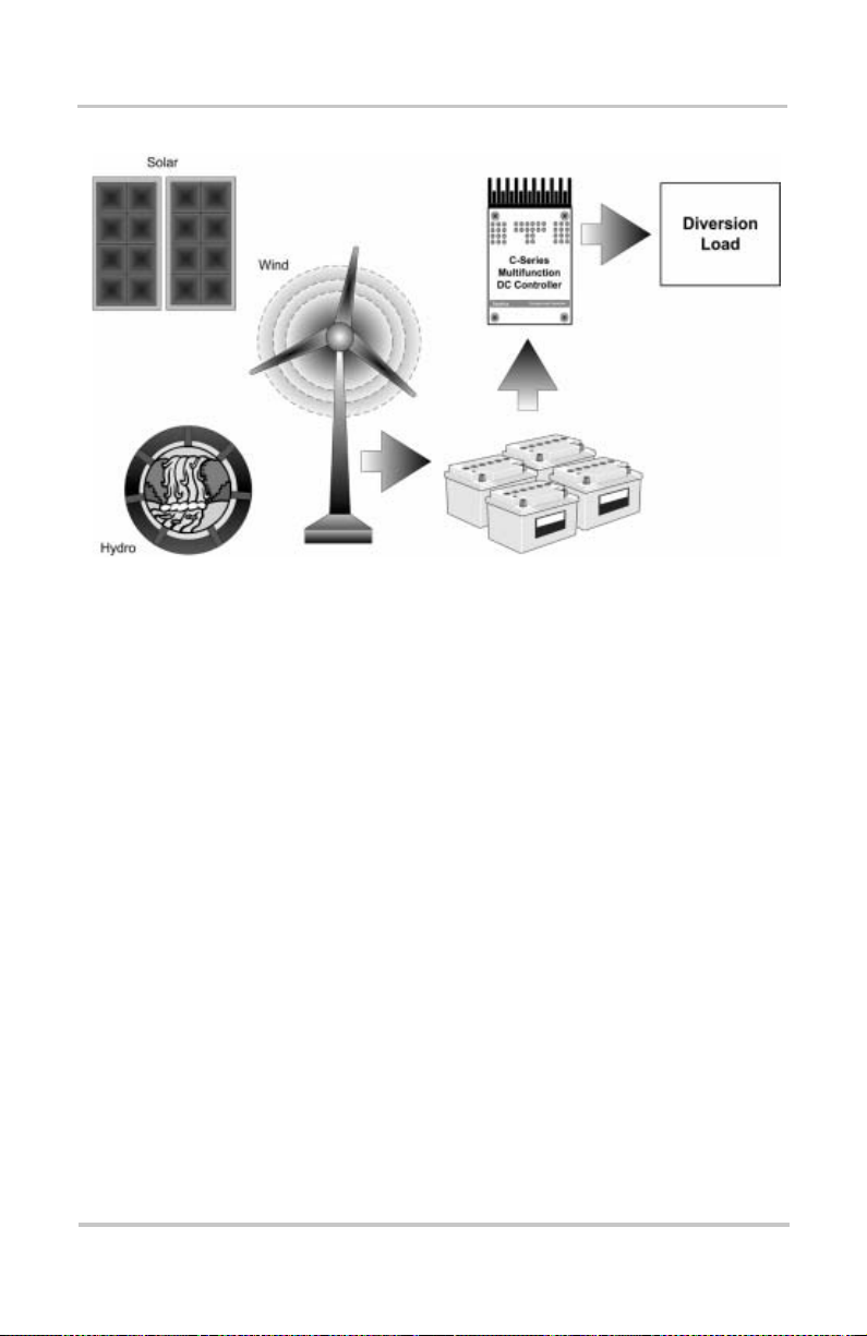
Diversion Controller
The C-Series controller can operate as a Diversion Controller ,
also called a shunt regula tor , to manage battery charg ing from
alternative energy sources such as PV, wind or hydroelectric
generators. A diversion controller monitors batte ry voltage
and, when the voltage exceeds the settings for your charge
stage (whether bulk or float), the power is diverted from the
source (solar, wind, or hydro generator) to a “dump” load
which will dissipate the excess power into heat.
When used for this purpose , the C-Series controller varies an
amount of battery voltage to a “dump load” in order to
redirect the excess powe r genera ted from over-charging the
batteries. This allows the charging sour ce to remain under
constant load to pr event an over-speed condit ion which c ould
occur if the chargi ng source is suddenly disconnected from
the battery–as serie s regulators do.
Consult your dealer for recomme ndations on diversion load
type and regulator size .
8 975-0004-01-02 Rev D
Page 29
Controller Functions
Figure 1-4
Diversion Controller
Diversion Loads
Diversion contr ol requir es a separ ate “dump ” load to regul ate
the battery. This load must be able to abso rb more po wer than
the charging source is able to produce at its peak output, or
the DC voltage will become unregulate d. The dump load
must be available for the diversion of power at all times.
Resistive-ty pe heating elements are the best diversion loads.
Special direct -c u rrent w ater h eat in g elem en ts are av aila b le.
Light bulbs and motors are not recommended as diversion
loads because they are unreli able. A diversion load that dr aws
about 25% more current than the charging source’ s maximum
output capability is usually suitable for use with the C-Series
controller.
See Appendix C, “Diversion Loads” for additional
information on types of diver sion loads.
See “Operating Mode Jumper” on page 20 for instructions on
enabling this mode.
975-0004-01-02 Rev D 9
Page 30

Introduction
Important:
may be necessary to install diodes to prevent night-time
back-feed. If in doubt, contact or consult with your local
renewable ener gy expert.
Important:
to prev ent back fe ed .
CAUTION: Damage to Batteries
Current draw of th e diver sion l oad i s very im portant . Prob lems m ay
arise from operating with a load that is too small or too large. A
diversion load that is too small will not be able to abs o r b all the
exces s power from the current source once the ba tteries are full
allowing batteries to overcharge.
Diversion loads in excess of the controller’s rating are capable of
absorbing more power than the C-Series controller is designed to
handle, res ult ing in an over -curr ent shut down. Dur ing thi s ti me, the
unit will not regulate electrica l flow in the system and battery
damage may result.
Load Controller
The C-Series controller can operate as a Low Voltage
Disconnect (LVD) for DC loads to prevent over-discharge to
batteries during pe riods of poor charging or excessive loads.
The C-Series controlle r uses the user-adjustable setpoints to
determine when to disconnect or reconnect loads depending
on battery voltage.
If PV arrays are used with diversion control, it
If using multiple RE sources, use diodes/isolation
When used as a DC load controller, the settings of the LVR
and LVD are controll ed by two rotary potentiometers (also
called pots) on the circuit board.
The scale on the adjustment potentiometers differ from the
scale used for other functions. A decal with the appropriate
adjustment scale is include d with the C-Series. To apply the
decal, gently pull off the knobs of the potentiometers and
place this decal on the circuit board. After the decal is in
place, replace the knobs. The EQ jumper deter mines manual
10 975-0004-01-02 Rev D
Page 31

or automatic reconnect when the C-Series is used as a load
controller. Do not use this decal if using the C-Series
controller as a PV Charge Cont roller or Diversion Controlle r.
Low Voltage Disconnect
When confi gured as a load controller , the C-Series controller
will disconne ct the loa d from the ba tterie s when it reaches the
LVD setting. There will be a 6-minute delay after the volt age
drops below the Low Voltage Disconnect (LVD) setting
before the controlle r actually disconnects the load.
Low Voltage Reconnect
It can also provide automatic reconnection of the loads at the
LVR (Low Voltage Reconnect) setting. Reconnection of the
load is allowed once the battery voltage has exceeded the
Low Voltage Reconnect (LVR) setting.
Loads are either automatically or manually reconnected when
battery voltage exceeds the Low Voltage Reconnect (LVR)
setting for 6 minutes.
Controller Functions
See “Operating Mode Jumper” on page 20 for instructions on
enabling this mode.
Figure 1-5
975-0004-01-02 Rev D 11
Load Controller
Important:
• Do not temperature-compensate these settings.
• Do not install the optional battery temperature
compensation sensor.
When using the DC Load Control mode:
Page 32

Introduction
A
p
L
S
Potentiometer knobs
ttach decal over
otentiometers f or
oad Control
ettings
Figure 1-6
Decal Displaying Load Control Voltage Settings
Optional Accessories
The follow accessories can be purchased for use with the
C-Series Multifunction DC Controlle r:
• Display Met ers : The CM faceplate or CM/R remote
display provide a digital display for monitoring the
C-Series controller’s operation. The CM faceplate
attaches directly to the front of the C-Series controller.
The CM/R is intended for remote applications. These
meters provide a digital display of current, voltage,
amperage, and amp hours.
• Battery Temperature Sensor (BTS): The BTS is
installed on the side of the batte ry and attaches to the
circuit board inside the C-Series controller. It provides
accurate sensing of the bat tery temperature and uses this
reading to control charging. Using this accessory can
extend battery life and improve overall charging.
BTS
CM/R
Figure 1-7
12 975-0004-01-02 Rev D
Optional Accessories - CM/R, CM, and BTS
CM
Page 33

2
Chapter 2 contains information and procedures to install
C-Series Multifunction DC Controller.
For information on: See:
“Pre-Installation” page 14
“Mounting the Controller” page 16
“Configuring the C-Series Controlle r” page 18
“Adjusting the C-Series Voltage Settings” page 22
“Grounding” page 37
“Wiring” page 38
“Installing Optional Accessories” page 50
“Installing the Ba ttery Temper ature Sensor” page 51
Installation
Page 34

Installation
Pre-Installation
The instruct ions that fo llo w are ap pl ic abl e to the typic al
installation. For special applications, consult a qualified
electrician or your Xantrex Certified Dealer. Installation
procedure s wil l vary acco r d ing to your s peci fi c app l icat ion.
Important:
standards . Installations of this equipment should only be
performed by skilled personnel such as qualifi ed electricians and
Certif i ed Ren e w ab l e En er gy (R E) System In sta llers. Fo r a li st of
Xantrex Certified RE de alers, please visit our website at
www.XantrexREdealers.com.
Installations should meet all local codes and
Removing the Top Cover
Access the inside of the controller by removing the four
phillips screws (#10-32 x 3/8" SMS screws) on the front
cover of the unit.
Remove these
phillips screws (x4)
from the front cove r
to access the inside
of the controller.
Figure 2-1
Removing Knockouts
Six dual-knockouts are pr ovided to accommodate the
Removing the Front Cover
necessary wiring of the C-Series controller. Be sure to
remove any metal shavings created by removing the
14 975-0004-01-02 Rev D
Page 35

Pre-Installation
)
knockouts before making any wiring c onnections. It is also
recommended to use bushings or conduits to pr otect the
wiring from damage from rough edges in the knockou t hole s.
Heatsink not
included on C35
8"
(203 mm)
Keyhole Slots for
mounting
2"
(51 mm)
1
8"
(203 mm
Additional Mo unting
Holes (x4)
2
½ and ¾"
Dual-Knockouts
6 7/8"
(174 mm)
2 ¼”
(64 mm)
This distance varies per model:
1
Side View
3 5/8”
(93 mm)
5”
(127 mm)
Rear View
C35 = 3/8"
C40, C60 = 5/8"
¾ and 1"
2
Dual-Knockouts (x4)
(1 on each side and 2 on the bottom of chassis)
Figure 2-2
C-Series Dimensions and Knockout Locations (Not to Scale)
975-0004-01-02 Rev D 15
Page 36

Installation
Mounting the Controller
The C-Series controller is designed for indoor mounting.
Care should be taken in selecti ng a location and when
mounting the enclosure. Avoid mounting it in direct sunlight
to prevent heating of the enclosure. The enclosure should be
mounted verticall y on a wall.
In outdoor installa tions, the C-Series controller must be
installed in a rainpro of encl osure to eliminate exposure to
rain, mist or water-spray.
CAUTION: Damage to C-Series Controller
Install the C-Series controller in a dry, protected location away
from sources of high temperature, moisture, and vibration.
Exposure to saltwater is particul arly destructive. Corrosion is not
covered by the warranty.
To mount the C-Series controller:
1. Remove the faceplate on the controller.
2. Place the controller on the desired mounting surface and
mark the location of the keyhole slots on the wall.
3. Move the controller out of the way, and secure two
mounting screws in the locations marked. Leave the
screw heads backed out approximately ¼ inch (6 m m)
or less.
4. Place the controller onto the screws and pull it down into
the keyhole slots.
5. Then insert the two more screws in two of the four
additional mounting hole s provided to secure the
enclosure o nto the w all .
6. Provide either strain-relief clamps or conduit to prevent
damage to the circuit board and terminal block from
pulling on the wires.
16 975-0004-01-02 Rev D
Page 37

WARNING: Explosion/Corrosion Hazard
Do not lo c ate the C-Series controller in a se aled compartm ent with
the batteries. Batteries ca n vent hydrogen-sulfide gas, which is
corrosive to electroni c e quipment. Bat terie s also ge nerate hydro gen
and oxygen gas that can explode when exposed to a spark.
If using “sealed” batteries, the controller can be mounted in
the same enclosure as long as it is adequately ventilated.
Place keyhole s lots on the back of th e
controller over t he mou nti ng screws.
Approximately
¼inch
Pre-Installation
Mounting
Screws
Mounting Surface
Secure in pl ace wi th
2 more screws.
Figure 2-3
Mounting the C-Series Multifunction DC Controller
975-0004-01-02 Rev D 17
Page 38

Installation
Configuring the C-Series Controller
Before making any wiring connect ions to the C-Series
controller, it must be configured for the desired mode of
operation. The following sections describe the how to
configure the unit for the desired application and function.
Jumper Settings
Three sets of jum pers are lo cat ed on t he right side of th e
controller’s circuit board. These jumpers control
equalization, low voltage reconnect, battery voltage, and
operating modes. They must be installed correc tly for the unit
to operate to its maximum pote ntial.
To enable a selection, carefully slide the jumper over the top
of both pins. This is called installing the jumper.
To disable a selection, carefully slide the jumper over only
one of the pins. This is called removing the jumper.
Jumper Removed
(Jumper is only on one pin)
Jumper
Jumper Installed
(Jumper is on both pins)
Figure 2-4
Jumper Positions
The factory defaul t settings are shown in Table 2-1, “Factory
Default Settings for C-Ser ies Controllers” on page 19.
Important:
jumpers so as not to bend the pins.
18 975-0004-01-02 Rev D
Use extreme caution when ins talling and removing
Page 39

Configuring the C-Series Controller
r
Table 2-1
Factory Default Settings for C-Series Controllers
Setting C35, C40 and C60
Battery Voltag e 12 volts DC
Equalize/LVR Manual Equalization
Operating Mode Charge Control
NiCad Setting
Selection R46
Resistor
Load Control
Decal
EQ/LVR
Jumper
Operating
Mode Jumper
Reset S w itch
Potentiometers
Voltage Jumpe
Battery
Temperature
Sensor Port
DC Terminal Connectors
CM or CM/R Port
Note: This photog raph shows the Load Control Voltage decal inst alled on the
circuit board over the pot entiometers.
Figure 2-5
Circuit Board Components
975-0004-01-02 Rev D 19
Page 40

Installation
Operating Mode Jumper
This jumper determines the operating mode. Place the jumper
over the pins that correspond to the desired mode.
• Charge Control (PV Charge Controller or Diversion
Controller)
• Load Control (Load Controller)
Factory default set ting is Charge Control mode.
Charge/Load
Control
Jumper
Charge Control Mode
Load Control Mode
Figure 2-6
Voltage Jumper
The voltage jump er determines the voltage of the system that
the controller will be used with. To set the voltage, place the
jumper over the two pins adjacent to the legend for the
voltage of your system: 12, 24, 48. Factory settin g is 12 volts
for the C35, C40, and C60.
C40 Models
C35 and C60
Models
Figure 2-7
Mode of Operation Jumper
12 Volt Position
24 Volt Position
48 Volt Position
12 Volt Position
24 Volt Position
Voltage Selection Jumper
20 975-0004-01-02 Rev D
Page 41

Configuring the C-Series Controller
Automatic/Manual Battery Equalization (EQ) and Low Voltage Reconnect (LVR) Jumper
Depending on the mode of operation chosen, this jumper
enables:
• automatic or manual battery equalization
(Charge Control mode) , or
• automatic or manual rec onne ct in the event of low
voltage event (Load Control mode).
When A
UTO is enabled in the Charge Control mode, the unit
will perform an equalizat ion charge every 30 days. This can
be done manually by using Reset Switch on the side of the
controller chas sis.
When AUTO is enabled in Load Control mode, the unit will
reconnect automati cally when voltage at the BATTERY
POSITIVE terminal exceeds the LVR setting. This can also be
done manually by using Reset Switch on the side of the
controller chas sis.
The factory default setting is M
ANUAL EQUALIZATION
(Charge Control mode).
Place the jumper over the pins for the desired selection.
EQ/LVR Jumper
MANUAL
AUTO
Figure 2-8
EQ/LVR Jumper and Reset Switch
See “Error Mode Indication (Orange)” on page 59 for
instructions on how to use the Reset Switch in relation to thi s
function.
975-0004-01-02 Rev D 21
Page 42

Installation
Adjusting the C-Series Voltage Settings
The charging volt age setpoints and voltage reconnect /
disconnect setti ng of the controller are adjustable using two
rotary potentiomet er controls. The knobs are removable to
reduce the likeliho od of accide ntal mis-adjustment if
bumped.
Calibrated scales, shown as scale marks, are provided to
allow setting of the contro l without requiring the use of a
digital voltmete r.
For more information regarding bulk and float charging
voltages, see “Three-Stage Battery Char ging” on page 4.
Setting indicator
Potentiometers
Figure 2-9
Scale Marks
Bulk and Float Charge Potentiometers (pots)
Setting Voltage Parameters for Charge Control Mode
To set the controller to a specific voltage, point the setting
indicator at the scale mark representing the desired voltage.
The potentiometer scal e for BULK charge voltage is
calibrated as follows:
• 12-volt system: 13.0 to 15.0 volts
in increments of 0.2 volts,
• 24-volt system: 26.0 to 30.0 volts
in increments of 0.4 volts,
• 48-volt system: 52.0 to 60.0 volts
in increments of 0.8 volts.
22 975-0004-01-02 Rev D
Page 43

Adjusting the C-Series Voltage Settings
1
)
)
1
2
)
)
2
5
)
)
5
For FLOAT charge voltage, the potentiometer scale is
calibrated follows:
• 12-volt system: 12.5 to 14.5 volts
in increments of 0.2 volts,
• 24-volt system: 25.0 to 29.0 volts
in increments of 0.4 volts, and
• 48-volt system: 50.0 to 58.0 volts
in increments of 0.8 volts.
14.8
15.0
14.6
14.4
14.2
4.0
13.8
13.7
3.5
13.3
13.6
13.9
13.1
13.4
14.1
12.9
13.2
14.3
12.7
BULK (CHG
13.0
14.5
FLOAT (CHG
12.5
8.0
27.6
27.4
7.0
26.6
12-Volt System Settin gs
59.2
60.0
58.4
57.6
56.8
6.0
55.2
54.4
53.6
52.8
57.2
56.4
55.6
54.8
4.0
53.2
52.4
51.6
48-Volt System Setti ngs (C40 only)
50.8
BULK (CHG
52.0
58.0
FLOAT (CHG
50.0
29.6
30.0
29.2
28.8
28.4
BULK (CHG
27.2
26.8
27.8
28.2
26.4
28.6
26.0
29.0
FLOAT (CHG
26.2
25.8
25.4
25.0
24-Volt System Settin gs
Figure 2-10
Bulk and Float Charge Settings for Charge/Diversion
Control Mode
975-0004-01-02 Rev D 23
Page 44

Installation
Setting Voltage Parameters for Load Control Mode
T o change the Low Voltage Disconnect (LVD) and Low
Voltage Reconnect (LVR) settings, use the same BULK and
FLOAT potentiometers. However, when the C-Series
controller is used for DC Load Control, the potentiometer’s
scale calibration is altered from what is printed on the circuit
board.
Figure 2-11
BULK Setting
Potentiometer
FLOAT Setting
Potentiometer
LVR Setting
LVD Setting
Potentiometers with Decal for LVR and LVD Settings
A decal is provided with the C-Series with the proper scale
calibrations for the Load Control mode. The BULK
potentiome te r be comes the Low Vol tag e Rec onn e ct (LVR),
and the FLOAT potentiometer becomes the Low Voltage
Disconnect (LVD).
Place the sticker provi ded over the potentiom eters. The knobs
may have to be removed for sticker placement, then
reinstalled. The sticker is packed inside the C-Series
controller (bottom of unit). If the decal is lost or unavailable,
you can recalculate the appropriate voltage settings as
follows:
The scale for the Low Voltage Reconnect setting is calibrated
as follows:
• 12-volt system: 12.0 to 14.0 volts
in increments of 0.2 volts,
• 24-volt system: 24.0 to 28.0 volts
in increments of 0.4 volts,
• 48-volt system: 48.0 to 56.0 volts
in increments of 0.8 volts.
24 975-0004-01-02 Rev D
Page 45

Adjusting the C-Series Voltage Settings
1
1
)
E
2
2
)
E
5
4
)
E
The scale for the Low Voltage Disconnect sett ing is
calibrated as follows:
• 12-volt system: 10.5 to 12.5 volts
in increments of 0.2 volts,
• 24-volt system: 21.0 to 25.0 volts
in increments of 0.4 volts, and
• 48-volt system: 42.0 to 50.0 volts
in increments of 0.8 volts.
27.6
13.8
14.0
3.0
12.8
11.7
1.5
11.3
13.2
12.6
11.9
11.1
13.4
13.6
12.4
12.1
10.9
12.2
12.3
10.7
12.0
12.5
10.5
.V.R (LOAD)
L
L
OW VOLTAGE
R
ECONNECT
L.V.D
(LOAD
L
OW VOLTAG
D
ISCONNECT
26.8
26.4
6.0
25.6
25.2
23.8
23.4
3.0
22.6
22.2
12-Volt System Setti ngs 24-Volt System Settin gs
27.2
24.8
24.2
21.8
24.4
24.6
21.4
28.0
24.0
25.0
21.0
L.V.R
(LOAD)
L
OW VOLTAGE
R
ECONNECT
L.V.D
(LOAD
L
OW VOLTAG
D
ISCONNECT
55.2
56.0
54.4
53.6
52.8
2.0
51.2
50.4
49.6
48.8
49.2
48.4
47.6
46.8
6.0
45.2
44.4
43.6
42.8
48.0
50.0
42.0
L.V.R
(LOAD)
L
OW VOLTAGE
R
ECONNECT
L.V.D
(LOAD
L
OW VOLTAG
D
ISCONNECT
48-Volt System Setti ngs (C40 only)
Figure 2-12
975-0004-01-02 Rev D 25
LVR and LVD Settings for Load Control Mode
Page 46

Installation
Setting Voltage Parameters Diversion Control Mode
When the C-Series controller is configured for Diversion
Control mode, you can set the voltage at which the unit
begins diverting current to a diversion load (high voltage
diversion). Use the Charge Control scale for settin g this
value.
See Figure 2-10 on page 23 for Charge Control scale settings.
The unit will continue diverting excess current to the
diversion load until the source voltage falls to or below the
BULK setting. After one hour at the BULK setting, the unit
will reduce the battery charging voltage to the FLOAT
voltage setting. This will usually result in more current being
diverted to the diversi on load.
Setting Voltage Parameters for Alkaline Batteries
If using NiCad or NiFe batteries, the required charging
voltages may be higher than the designed settings of the
C-Series controller. Charging voltages can be augmented a
little, if required. This can be accomplished by clipping the
wire connecting the R46 Resistor to the circuit board. This
augmentation will rai se the designed charge parameter s by
2 volts for 12-volt syst ems, 4 volts for 24-volt systems and
8 volts for 48-volt syst ems.
See Figure 2-14 for the augmented voltage setting s.
If using NiCad batter ies,
clip this wire her e. Do NOT
remove the R46 Resistor.
R46 Resistor
Circuit Board
Figure 2-13
26 975-0004-01-02 Rev D
R46 Resistor Location
Page 47

1
)
16.8
)
1
3
)
)
3
6
)
)
6
17.0
16.6
16.4
16.2
6.0
15.8
15.7
5.5
15.3
15.6
15.9
15.1
15.4
16.1
14.9
15.2
16.3
14.7
BULK (CHG
15.0
16.5
FLOAT (CHG
14.5
12-Volt System Settings
Adjusting the C-Series Voltage Settings
33.6
33.2
32.8
32.4
2.0
31.6
31.2
30.8
30.4
32.6
32.2
31.8
31.4
1.0
30.6
30.2
29.8
29.4
24-Volt System Settin gs
67.2
68.0
66.4
65.6
64.8
4.0
63.2
62.4
61.6
60.8
65.2
64.4
63.6
62.8
2.0
61.2
60.4
59.6
58.8
48-Volt System Setti ngs (C40 only)
BULK (CHG
60.0
66.0
FLOAT (CHG
58.0
34.0
BULK (C HG
30.0
33.0
FLOAT (CHG
29.0
Figure 2-14
Voltage Settings with R46 Resistor Clipped
CAUTION: Damage to Batteries
It is not re co mmend e d to allow an eq ualize charge to occur if the
R46 Resistor is clipped. Higher charging voltages may damage the
batteries. Make sure the EQ/LVR jumper is on the MANUAL
Setting.
975-0004-01-02 Rev D 27
Page 48

Installation
Using a Digital Voltmeter to Adjust Voltage Settings
A digital DC vol tmeter ( DVM) can be use d to pr ovide a more
accurate setting of voltage parameters. Test points are
provided at the mid-range on the sca les for this purpose.
The potentiometers are eq uipped with removable knobs to
prevent accidental mis-adjustments. If the knobs are missing,
a 5/64" hex-head driver can be used to adjust the settings.
To test and adjust the voltage setting using a DVM:
1. Point the potentiometers to the mid-range position.
2. Connect a digital voltmeter from one of the common
negative terminals on the circuit board and the small test
point located to the left of each potent iometer at the
nine o’clock position. See Figure 2-15.
The test point provides a readi ng from 0 to 2 volts.
(Multiply this value by “2” for 24-volt system and by
“4” for 48-volt system.)
3. Add the value obtained in step 2 above to the lower value
of the adjustment range/voltage scale being used.
For example f or a 12-vo lt syst em:
To set the BULK voltage to 14.4 volts:
1. Point the BULK potentiometer to the mid-range position.
2. Adjust the potentiometer until the DVM displays
1.4 volts (13.0 V + 1.4 V = 14.4 V).
For example f or a 24-vo lt syst em:
To set BULK voltage to 28.2 volts:
1. Point the BULK potentiometer to the mid-range position.
2. Adjust the potentiometer until the DVM displays
1.1 volts (1.1 x 2 [24 volt] = 2.2 + 26.0 = 28.2).
28 975-0004-01-02 Rev D
Page 49

Adjusting the C-Series Voltage Settings
For example f or a 48-vo lt syst em:
To set BULK voltage to 56.4 volts:
1. Point the BULK potentiometer to the mid-range position.
2. Adjust the potentiometer until the DVM displays
1.1 volts (1.1 x 4 [48 volt] = 4.4 + 52.0 = 56.4).
TEST POINTS for DVM
(center legs of
potentiometer)
Battery Common Negative
Terminals
Figure 2-15
975-0004-01-02 Rev D 29
Test Points for Adjusting Voltage Using a DVM
Page 50

Installation
Equalization Charging
CAUTION: Damage to Batteries
:
Equalization should be done for standard electrolyte, vented
batteries only. Sealed, GEL cell, or NiCad batteries s hould not be
equalize- charged. Consult your battery supplier for details on
equalize- charging for the battery type in your system .
The C-Series offers either manual or automatic triggering of
the equalization charging process. Equalization charging is
the deliberate proc ess of charging a battery (or battery bank)
at a high voltage for a set period of time to remix the
electrolyte and destratify the internal plates. Equalize
charging he lps to r emove sulf ate bui ldup on the ba ttery pla tes
and balances the charge of individual cells.
Equalization char ging holds the voltage above the BULK
setting for 2 hours by 1 volt for 12-volt syste ms, 2 volts for
24-volt systems, and 4 volts for 48-volt systems.
The default setting for this feature is M
ANUAL. Automati c
equalization is enabled by moving the jumper located on the
right side of the circuit board above the reset switc h to the
appropriate A
Figure 2-16
UTO pin set. See Figure 2-18
Manual Equalize
(Default Setting)
Auto Equalize
Manual Equalization Settings
When autom ati c ha s bee n select ed , an equal izat i on cha rge
will occur every 30 days.
During the equalizati on process, the status LED indicates
equalization by alte rnately blinking green and red.
Important:
power is removed from the controller .
30 975-0004-01-02 Rev D
The auto equalization period is reset wh en DC
Page 51

Manual Equalization
F
(
d
Manual equalization of the battery can be enabl ed by pressing
the Reset Switch on the right side of the C-Series until the
status LED indicator begins to a lternate between red and
green. This could take about 10 seconds.
ront Panel LED
flashes red/g reen
uring equalizati on)
Equalization Charging
Reset
Switch
Access
Figure 2-17
Front Panel LED and Reset Switch Location
The equalization pr ocess will conti nue until the batte ries have
been held at or above the bulk setting for two hour s of
accumulated time. Once the battery voltage has been at or
above the bulk setting for a cumulative period of two hours,
the C-Series will return to the float stage of the charging
process.
During the equalization process, the status LED will alternate
between red and green and will not provide any other
mode/status indi cati on. Lar ge batter y banks may need sever al
equalization cycles to fully stir the electrolyte and charge the
cells. These cycles shou ld follow one another until the bat tery
voltage reaches the upper lim it for the full two hours.
975-0004-01-02 Rev D 31
Page 52

Installation
Automatic Equalization
The C-Series controller can automa tica l ly trigg er an
equalization charge every 30 days. The status LED will
indicate that the equalization process is occurring.
The equalization proce ss will c ontinue until the voltage has
been held above the bulk setting for a cumulative period of
two hours. This might take several days on larger systems
with big batteries and small PV arrays. The battery voltage
only needs to exceed the bulk setting for the timer to start
counting–the voltage may not reach the equalization voltage
setting.
To enable auto ma tic eq ual i zati o n, the jum p er locat ed on t he
right side of the circuit boa rd must be moved to the A
setting. The default setting of the C-Seri es co ntr o ller is for
manual equalization. To disable the automatic equalization
system, move the equalize jumper to MANUAL.
UTO
Manual Equalize
Auto Equalize
Figure 2-18
Auto Equalization Settings
Once a manual equalization has been triggered, the 30-day
period to the next autom atic equaliz ation wil l be resta rted. To
prevent automatic equalization, move the equalize jumper to
the manual position.
Important:
It is not r ecommended to use the Equalization
feature if the R46 Resistor is cl ippe d.
32 975-0004-01-02 Rev D
Page 53

Temperature Compensation
Terminating the Equalization Process
T o stop the equa lizat ion process, press the reset switc h on the
right side of the unit until the status LED stops alternating
between red and green.
If the equalization pr ocess was shorter than one hour , the
controller will continue with a bulk charge cycle and then
hold the battery at the bulk setting for one hour (the
absorption stage) before returning to the float setting.
Front Panel LED
(flashes red/green
during equalization)
Press Reset
Switch until LED
stops alternating
between red and
green
Figure 2-19
Terminating the Equalization Charge
Temperature Compensation
Important:
• Do NOT compensate the se ttings.
• Do not install the Battery Temperature Sensor.
For optimal batte ry charging, the Bulk and Float charge rate s
should be adjusted according to the temperature of the
battery. When battery charging voltages are compensated
based on temperatur e, th e charge volta ge will va ry depen ding
on the temperature around the batteries.
975-0004-01-02 Rev D 33
If using the C-Series as a DC Loa d Co n troller:
Page 54

Installation
Temperature Compensation Based on Battery Type
The C-Series controller uses the battery type to determine the
temperature compensated voltage settings. The temperature
compensated char ging voltage is normally based on a Lead –
Acid types of battery.
If using Alkaline-type batteries, the R46 resistor on the
circuit board inside the controller will have been clipped as
shown in “Sett ing Voltage Paramete rs for Alka line Batter ies”
on page 26. If the R46 resistor is cut, the temperature
compensation charging voltage will be based on
Alkaline-type batteries.
See the battery type below to determine the temperature
comp ensation value chan ge per temperature or refer to t he
temperatu re compensation cal cu lat io ns fo r a Lead -A cid typ e
battery as show in Table 2-2.
• Lead-Acid T ype Batteries:
5 mV per cell per degree Celsius
• Alkaline -Type Batterie s (NiC a d or N iFe ):
2 mV per cell per degree Celsius
T able 2-2 describes approximately how much the volta ge
may vary depending on the temperature of the batt eries.
Automatic Battery Temperature Compensation
Temperature compens ation can be acco m p lish ed
automatically by using a Batt ery Temperature Sensor (BTS).
The sensor attac hes directly to the side of one of the batteries
in the bank and provides precise bat tery temperature
information.
See “Installing the Battery Temperature Sensor ” on page 51
for detailed instr uctions on how and where to inst all the BTS.
If a BTS is installed, the charge controlling process will be
automatically adjusted for the battery temperature. When
using a BTS, set the Bulk and Float voltage for a batter y at
normal room temperature for 77 °F (25 °C).
34 975-0004-01-02 Rev D
Page 55

Temperature Compensation
Table 2-2
Variances in Charging Voltage based on Battery Temperature
Temperature
(around the BTS) 12-volt units 24-volt units 48-volt units
Celsius Fahrenheit
Lead
Acid
(6 cells)
NiCad
(10 cells)
Lead
Acid
(12 cells)
NiCad
(20 cells)
Lead
Acid
(24 cells)
NiCad
(40 cells)
60 140 -1.05 -0.70 -2.10 -1.40 -4.20 -2.80
55 131 -0.90 -0.60 -1.80 -1.20 -3.60 -2.40
50 122 -0.75 -0.50 -1.50 -1.00 -3.00 -2.00
45 113 -0.60 -0.40 -1.20 -0.80 -2.40 -1.60
40 104 -0.45 -0.30 -0.90 -0.60 -1.80 -1.20
35 95 -0.30 -0.20 -0.60 -0.40 -1.20 -0.80
30 86 -0.15 -0.10 -0.30 -0.20 -0.60 -0.40
25 77 0.00 0.00 0.00 0.00 0.00 0.00
20 68 0.15 0.10 0.30 0.20 0.60 0.40
15 59 0.30 0.20 0.60 0.40 1.20 0.80
10 50 0.45 0.30 0.90 0.60 1.80 1.20
5 41 0.60 0.40 1.20 0.80 2.40 1.60
0 32 0.75 0.50 1.50 1.00 3.00 2.00
-5 23 0.90 0.60 1.80 1.20 3.60 2.40
-10 14 1.05 1.20 2.10 1.40 4.20 2.80
-15 5 1.20 0.80 2.40 1.60 4.80 3.20
-20 -4 1.35 1.40 2.70 1.80 5.40 3.60
-25 -13 1.50 1.00 3.00 2.00 6.00 4.00
-30 -22 1.65 1.10 3.30 2.20 6.60 4.40
-35 -31 1.80 1.20 3.60 2.40 7.20 4.80
-40 -40 1.95 1.30 3.90 2.60 7.80 5.20
975-0004-01-02 Rev D 35
Page 56

Installation
If using a BTS, when the battery temperature drops below
77°F (25 °C), the regulation voltage setting automatically
increases. When the t emperature rises a bove 77° F (25 ° C) the
regulation battery voltage se tting automatically decreases.
Manual Battery Temperature Compensation
If no Battery Temperature Sensor (BTS) is installed and the
batteries will be operatin g in very hot or very cold conditions,
adjust the bulk and float sett ings to allow for the battery
temperature.
The recommended adjustments c an be made following Table
2-2. The setting should be lowered for ambient temperatures
above 86 °F (30 °C) and raised for ambient temperature
below 68 °F (20 °C).
If significant seasonal variations are common, you will have
to change the settings sever al ti mes a year to preve nt battery
damage and ensure proper operat ion.
Important:
wires are shorted or cut, the system will return to the
non-tempera ture compensated settings.
36 975-0004-01-02 Rev D
If the wiring to the sensor is damaged and the
Page 57

Grounding
The C-Series controller is designed to work with both
negative ground and unground ed electrical systems. The
metal chassis of this char ge/loa d controlle r must be grou nded
for either system by connecting it with a copper wire to a
grounding electrode such as a ground rod driven into the
earth.
If a negative ground system is desired, connect the negative
current carryin g conductor to the grounding system at one
point in the system. Consult local and national electrical
codes for more information and any additional requirements.
T elecom applicatio ns often require a positive gr ound system.
The C-Series controller switches the PV+/L
with th e BATTERY POSITIVE (+) terminal. These te rm inals
must be kept separate. You can ONLY ground the battery
positive lead in this case , if your loca l jurisdiction allows it.
Grounding
OAD+ terminal
This symbol repr esents a
Safety (Earth) Ground.
Chassis Ground Lug
Figure 2-20
Grounding the C-Series Chassis
WARNING: Shock Hazard
Do not disconnect the chassis ground if loads are enga ged.
975-0004-01-02 Rev D 37
Page 58

Installation
Wiring
Important:
standards . Installations of this equipment should only be
performed by skilled personnel such as qualifi ed electricians and
Certif i ed Ren e w ab l e En er gy (R E) System In sta llers. Fo r a li st of
Xantrex Certified RE de alers, please visit our website at
www.XantrexREdealers.com.
Installations should meet all local codes and
WARNING: Shock Hazard
Disconnect batter y and PV sources before wiring.
CAUTION: Damage to Batteries
Ensure the volta ge selection jumper is set properly before
energizing the system. Incorre ct settings may result in dam age to
the system as charging regulation will not occur.
DC Terminal Connector Locations
T erminal connectors for DC wiring are located on the lower
edge of the circuit board. See Figure 2-21.
Important:
conductor from a PV array OR a DC load may be connected to
the terminal marked “PV+/ LOAD+”.
The common negatives can be reversed or wired with an
appropriately siz ed single conductor to a more convenient
location suc h as a DC load cen ter negative bus, if neces s ary.
The shunt used to measure the current flow in the C-Series
controller is loca ted in the positive conductor of the circuit
allowing greater fle xibility in system grounding. The
negative terminals a re all common to one another.
38 975-0004-01-02 Rev D
Regardless of the configuration, only the positive
Page 59

Terminal Torque Requirements
Once the wire s have b een inst alle d , torque the terminals as
follows. Be careful not to overtighten.
• 20 inch-pounds for #14-10 AWG wire
• 25 inch-pounds for #8 AWG wire
• 35 inch-pounds for #6 AWG wire
Wiring
Positive (+)
Figure 2-21
Battery
DC Connection Terminals
PV+/Load+ Negatives Negatives
Common to each other
Wire Size and Over-current Protection Requirements
The wiring, over- curre nt protec tion device s (fuses an d circuit
breakers), and installation methods used must conform to all
national and local electrical code requirements.
Wiring should be protected from physical damage with
conduit or a strain relief clamp. You should pull the
temperature sensor cable through the conduit first as the
connector may not fit if other wires have been pulled first.
Current Rating
Each model of the C-Series controller is rated for a maximum
continuous current of 35, 40 or 60 amps. Since PV outputs
can vary due to the array size or sunlight striking it, the safe
minimum wire size should be based on the maximum current
ratings.
975-0004-01-02 Rev D 39
Page 60

Installation
D
Minimum Recommended Wire Gauge
The minimum recommended wire gauge is:
• C35 and C40 Models:
#8 AWG with a 75 °C (167 °F) insulation rating
• C60 Models:
#6 AWG, with a 90 °C (194 °F) insulation rating
Size
iameter
Size
Diameter
Figure 2-22
The terminals on the C-Series will accept up to #2 AWG
2
(33.6 mm
) copper or aluminum wire. However, UL
specifications only allow the use of up to #6 AWG
(13.3 mm2) maximum.
No crimp-on terminals or lugs are requir ed.
12
14
.07210.1158.1466.184
.073
1
.335
1/0
.380
2/0
.420
.235
3/0
.475
4
3
.281
.530
2
.295
4/0
AWG Wire Gauge Reference Chart
Important:
for the conductor. Do not include any insulation when
determining your wire size. Due to printing anomalies, these
dimensions may not be to scale.
Figure 2-22 is for reference only. Sizes shown are
Surge Protection
Since PV array s are of te n mo unt ed o n an elev at ed stru c ture
and thus are more susceptible to lightning strikes, protection
from lightning-in duced power surges and other transi ent
40 975-0004-01-02 Rev D
power disturbances between the PV array and the C-Series
Page 61

controller are str ongly recommended. Put a surge protection
device on the input line of the C-Series con troller between
the PV array and the controller.
If the battery, is over 15 feet away from the controller, or if it
is routed next to other wiring or sour ces of power, additional
surge protection devices a re recommended. Put the surge
protection device for this scenario on the battery input line
between the battery and the controller.
Over-current Protection
The NEC requires conductors and over -current devices be
operated at no more than 80% of their rating. Ref er to Table
2-3 for a listing of the minimum wire size and over -current
device ratings to be used for each model.
As a minimum , a 60- am p DC- rat ed current-limitin g fuse o r
circuit breaker should be installed near the battery for
protection from short ci rcuits. To meet NEC requirements,
use a 60 amp cir cuit b reaker l isted f or 10 0% duty for the C60.
T o meet UL requirements, use #6 AWG copper wires rated
for 90 °C (194 °F) for the C60. Over-current protection for
the battery circuit is to be provided by others. Refer to
Table 2-3 for the correct ratings of the fuse and circuit
breaker.
Wiring
Table 2-3
Controller Minimum Wire Size Over-Current Device Rating
C35 #8 AWG 45 amps
C40 #8 AWG 50 amps
a
C60
C60
a.To meet U L requirements , use #6 AW G, (90 °C/194 °F) wire and a 60 amp Listed 100%
duty over-current device for the C60 controller.
b.Not appr oved by UL f or direct connection into the controller. Use a splicer block and #6
AWG (90 °C/194 °F) wire to connect to the controller terminals.
975-0004-01-02 Rev D 41
Minimum Wire Size
#6 AWG (90 °C/194 °F wire) 60 amps (listed 100% duty)
#4 AWG
b
(75 °C/167 °F wire)
60 amps (listed 100% duty)
Page 62

Installation
Long-distance wire runs
If there is a significant distance between the PV array and the
controller and/or the controller and the battery, larger wires
can be used to reduce the voltage drop and improve
performance. Refer to Table 2-4.
T o use a larger size wire, use a splicer block (terminal block)
intended for this purpose. This allows the larger cable size
from the batteries to be “spliced” to the smaller wire size
connected to the controller. Split-bolt kerneys can also be
used for wire spli ce s.
Follow manufactures recom menda tions for torque and
mounting (if required) . Sp licer blocks and split-bolt kerneys
are available from renewable energy suppliers.
Maximum One-way Distance and Wire Size
Important:
be consulted for wire s izing and any addition al installation
requirements.
• For a C60 use a 60 amp, 100% Continuous Duty breaker and
#6 AWG, 90 °C wire.
• Larger wire sizes may be used to improve performance, but
are NOT approved by UL to be installed in the controller. Use
a splicer block as prev ious ly described.
NEC Article 690 and local electrical codes should
Refer to Ta ble 2 -4 and find your maximum current in the left
column, and the one-way distance from your power source
(feet/meters) to the C-Series con tro ller (or the distance from
the C-Series controller to your load) on the same line, then
read the wire size required at the top of the column.
42 975-0004-01-02 Rev D
Page 63

Wiring
Table 2-4
One-Way Wire Distance and Wire Size
Maximum One-way Wire Distance for a < 3% Voltage drop
For 24 Vdc Systems, Multiply distance by 2
For 48 Vdc Systems, Multiply distance by 4
Distance in Feet (meters)
12
Amps
10
12
14
16
18
20
25
30
AWG
8.8 ft.
(2.68 m)
7.3 ft.
(2.23 m)
6.3 ft.
(1.92 m)
5.5 ft.
(1.68 m)
4.9 ft.
(1.49 m)
4.4 ft.
(1.34 m)
10
AWG8 AWG6 AWG
14 ft.
(4.27 m)
11.6 ft.
(3.54 m)
10 ft.
(3.05 m)
8.7 ft.
(2.65 m)
8.8 ft.
(2.38 m)
7 ft.
(2.13 m)
5.6 ft.
(1.71 m)
4.7 ft.
(1.43 m)
35
40
45
50
60
12 Vdc Application Shown
4
AWG3 AWG2 AWG1 AWG
22.2 ft.
(6.77 m)
18.5 ft.
(5.64 m)
15.9 ft.
(4.85 m)
13.9 ft.
(4.24 m)
12.4 ft.
(3.78 m)
11.1 ft.
(3.38 m)
8.9 ft.
(2.71 m)
7.4 ft.
(2.26 m)
6.4 ft.
(1.95 m)
5.6 ft.
(1.71 m)
35.3 ft.
(10.76 m)
29.4 ft.
(8.96 m)
25.2 ft.
(7.68 m)
22.1 ft.
(6.74 m)
19.6 ft.
(5.97 m)
17.6 ft.
(5.36 m)
14.1 ft.
(4.30 m)
11.8 ft.
(3.60 m)
10.1 ft.
(3.08 m)
8.8 ft.
(2.68 m)
7.8 ft.
(2.38 m)
7.1 ft.
(2.16 m)
6.3 ft.
(1.92 m)
56.1 ft.
(17.10 m)
46.7 ft.
(14.23 m)
40.1 ft.
(12.22 m)
35.0 ft.
(10.67 m)
31.2 ft.
(9.51 m)
28.0 ft.
(8.53 m)
22.4 ft.
(6.83 m)
18.7 ft.
(5.70 m)
16.0 ft.
(4.88 m)
14.0 ft.
(4.27 m)
12.5 ft.
(3.81 m)
11.2 ft.
(3.41 m)
9.3 ft.
(2.83 m)
Distance in Feet (Meters)
1/0
AWG
70.9 ft.
89.6 ft.
112.5 ft.
(21.61 m)
59.1 ft.
(18.01 m)
50.6 ft.
(15.42 m)
44.3 ft.
(13.50 m)
39.4 ft.
(12.01 m)
35.4 ft.
(10.79 m)
28.3 ft.
(8.63 m)
23.6 ft.
(7.19 m)
20.2 ft.
(6.16 m)
17.7 ft.
(5.39 m)
15.7 ft.
(4.79 m)
14.2 ft.
(4.33 m)
11.8 ft.
(3.60 m)
(27.31 m)
74.6 ft.
(22.74 m)
64.0 ft.
(19.51 m)
56.0 ft.
(17.07 m)
49.8 ft.
(15.18 m)
44.8 ft.
(13.66 m)
35.8 ft.
(10.91 m)
29.9 ft.
(9.11 m)
25.6 ft.
(7.80 m)
22.4 ft.
(6.83 m)
19.9 ft.
(6.07 m)
17.9 ft.
(5.46 m)
14.9 ft.
(4.54 m)
(34.29 m)
93.7 ft.
(28.56 m)
80.4 ft.
(24.51 m)
70.3 ft.
(21.43 m)
62.5 ft.
(19.05 m)
56.2 ft.
(17.13 m)
45.0 ft.
(13.72 m)
37.5 ft.
(11.43 m)
32.1 ft.
9.78 m)
28.1 ft.
(8.56 m)
25.0 ft.
(7.62 m)
22.5 ft.
(6.86 m)
18.7 ft.
(5.7 m)
141.7 ft.
(43.19 m)
118.1 ft.
(36.00 m)
101.2 ft.
(30.85 m)
88.6 ft.
(27.01 m)
78.7 ft.
(23.99 m)
70.9 ft.
(21.61m)
56.7 ft.
(17.28 m)
47.2 ft.
(14.39 m)
40.5 ft.
(12.34 m)
35.4 ft.
(10.79 m)
31.5 ft.
(9.60 m)
28.3 ft.
(8.63 m)
23.6 ft.
(7.19 m)
a
2/0
AWG
225.8 ft.
(68.82 m)
188.2 ft.
(57.36 m)
161.3 ft.
(49.16 m)
141.2 ft.
(43.04 m)
125.5 ft.
(38.25 m)
112.9 ft.
(34.41 m)
90.3 ft.
(27.52 m)
75.3 ft.
(22.95 m)
64.5 ft.
(19.66 m)
56.5 ft.
(17.22 m)
50.2 ft.
(15.30 m)
45.2 ft.
(13.78 m)
37.6 ft.
(11.5 m)
a.These wire siz es ar e not appr oved by UL t o be i nstal led i n the con trol ler, bu t may be us ed
externally of the controller (using a splicer block) to reduce voltage drop and improve
performance.
975-0004-01-02 Rev D 43
Page 64

Installation
PV Charge Control Mode Wiring
The procedure below is illustr ated in Figure 2-23.
WARNING: Shock Hazard
PV arrays generate voltage whenever light strikes the s urface of the
array. Before connecting the C-Series cont roller, cover or
disconnect the array to prevent any current from being generated.
To connect the C-Series controller as a charge controller:
1. Connect the PV array’s positive (+) output to the PV
array disconnect.
2. Route another (+) cable from the other end of the RE
disconnect to the PV GFP.
3. Route another (+) cable from the same switch in the PV
GFP to the terminal marked
controller.
4. Connect the PV array’s negative (–) output to the
terminal m arked C
OMMON NEGATIVES.
PV POS/LOAD in the C-Series
5. Connect another negative (-) cable from the other
COMMON NEGATIVES to the Ne gative b us in th e DC
disconnect.
6. Route a negative (–) wir e from the PV GFP to the
Negative bus in the DC disconnect.
7. Connect a positive (+) cable from terminal marked BAT
POS to the battery disconnect in the DC disconnect.
8. Connect a second positive (+) cable to the other side of
the battery disconne ct in the DC disconnect and connect
to the positive (+) battery terminal.
9. Connect the negative (–) batte ry cable to the negat ive bus
in the DC disconnect and tighten the lugs .
10. Tighten per torque requirements outlined on page 39.
Allow a litt le sl ack on t he c ables wit hin the c ontrol ler and
secure the wiring with stra in relie fs.
44 975-0004-01-02 Rev D
Page 65

Battery
Positive (+)
PV+ A rray
Positive (+)
Battery
Negative (–)
PV Array
Negative (–)
3
Wiring
Common
Negatives
4
Figure 2-23
1
2
8
9
Ensure the proper groundi ng is in
A
place for the entire system.
PV Charge Control Mode Wiring
7
6
A
5
975-0004-01-02 Rev D 45
Page 66

Installation
Diversion Control Mode Wiring
The procedure below is illustr ated in Figure 2-24.
When using the C-Series unit as a Diversion or DC Load
Controller, the DC load needs to be connected to the
controller terminals marked as
NEGATIVE.
To connect the C-Series as a diversion load controller:
1. Connect your DC current source (PV, wind, hydro, etc.)
directly to the RE disconnect .
2. Connect another cable from the other side of the RE
disconnect to the batte ry positive terminal.
3. Run a negative wire from the DC current source (PV,
wind, hydro, etc.) to the battery negative terminal.
4. Connect a cable from controller terminal marked BAT
POS to the battery disconnect.
5. Connect a cable from the battery disconnect to the
positive terminal of the battery.
PV +/LOAD+ and COMMON
6. Connect a cable from the negative ba tt ery termi nal to one
of the termin als marked C
OMMON NEGATIVES on the
controller’s circuit board.
7. Connect a cable from the controller’s other terminal
marked C
OMMON NEGATIVES to the negative terminal of
your DC diversion load.
8. Connect a cable from the controller’s terminal mar ked
PV+/LOAD+ to the positive terminal of your DC
diversion load.
9. Tighten per torque requirements outlined on page 39.
Allow a litt le sl ack on t he c ables wit hin the c ontrol ler and
secure the wiring with stra in relie fs.
Important:
only resistive loads such as air- or wat er-cooled heating elements
46 975-0004-01-02 Rev D
Do not use light bulbs for dive rsion loads. Use
Page 67

Battery
Positive (+)
Diversion Load
Positive (+)
1
Battery
Negative (–)
Wiring
Common
Negatives
Diversion Load
Negative (–)
Figure 2-24
2
3
5
A
Ensure the proper grounding is in
place for the entire system.
Diversion Control Mode Wiring
4
A
7
68
975-0004-01-02 Rev D 47
Page 68

Installation
DC Load Control Mode Wiring
The procedure below is illustr ated in Figure 2-25.
To connect the C-Series controller as a DC load
controller:
1. Connect a cable from the
controller to a batter y disconnect.
2. Connect the positive battery cable to the battery
disconnect.
3. Connect the negative battery cable to the one of the
terminals marked
4. Connect a cable between the
the controller and the positive terminal on the DC load.
5. Connect a cable between the controller’s other
NEGATIVES terminal and to the negative terminal of the
load.
6. Tighten per torque requirements outlined on page 39.
Allow a litt le sl ack on t he c ables wit hin the c ontrol ler and
secure the wiring with stra in relie fs.
COMMON NEGATIVES.
BAT POSITIVE terminal on the
PV POS/LOAD terminal on
COMMON
48 975-0004-01-02 Rev D
Page 69

Battery
Positive (+)
DC Load
Positive (+)
Battery
Negative (–)
Wiring
Common
Negatives
DC Load
Negative (–)
3
5
4
Figure 2-25
1
2
Load Control Mode Wiring
975-0004-01-02 Rev D 49
Page 70

Installation
Installing Optional Accessories
The following sections describe how to install the optional
accessori es ava ilab le fo r the C-Series Multifunction DC
Controller.
Installing a Digital Display
Follow the instructi ons in the C-Series Meter Displays
Installation Guide for preparing the CM or CM/R for
installation.
The display will conne ct to t he cont roller at th e RJ-15 por t on
the lower left corner of the circuit board.
Important:
or CM/R match the system voltage as configu r ed inside the
controller unit. See the C-Series Meter Displays Installation
Guide for addition al i nform ation.
C-Series Circuit Board
Serial Communication Cable
Ensure the voltage jumpers on the back of the CM
Digital Meter Display Port
RJ-15 Port
Figure 2-26
50 975-0004-01-02 Rev D
Installing a Digital Display
Page 71

Installing Optional Accessories
Installing the Battery Temperature Sensor
To install the BTS:
1. Install the BTS on the side of the battery below the
electrolyte level. It is best to place the sensor between
batteries and place the batteries in an insulated box to
reduce the influence of the ambient temperature outside
the battery enclosure .
2. Insert the RJ-11 plug on the other end of the BTS into the
BTS Port on the lower right corner of the circuit board
insi d e th e C-Series controller.
Important:
to prevent hydrogen accumulation.
C-Series Circuit Board
Ventilate the battery box at the highest point
Battery Temperat ure Sensor Port
RJ-11 Port
Figure 2-27
975-0004-01-02 Rev D 51
Installing the BTS
Page 72

Installation
Reinstalling the Faceplate
To reinstall the faceplace on the C-Series cont rolle r:
1. Align faceplate with front of chassis so that screw holes
in the corners line up.
2. Insert the phillips screws into the screw holes and
tighten.
Align these screw holes.
Replace the philli ps screws
to secure the faceplate.
Figure 2-28
52 975-0004-01-02 Rev D
Re-installing the CM Faceplate
Page 73

3
Chapter 3 contains information about the operation of a
C-Series Multifunction DC Controller.
For Information on: See:
“Basic Operation” page 54
“LED Status Indicat or” page 55
Operation
“Charge Control or Diversion Control
Indications (Green)”
“Load Control Indications (Red)” page 58
“Error Mode Indication (Orange)” page 59
“Reconnecting to Lo ads” page 60
page 56
Page 74

Operation
Basic Operation
The C-Series controller (all models) has one multicolor LED
status indicator and one reset button.
Multicolor LED
indicator
Reset Switch
(on side of unit)
Reset Switch
Figure 3-1
54 975-0004-01-02 Rev D
C-Series Status LED and Reset Button Location
Page 75

LED Status Indicator
The multicolor LED on the base unit, or the optional CM
faceplate or CM/R remote, indicate s the operating status of
the controller. A color-coded label is include d on the cover of
the controller expl aining the status LED’s indications.
• When in Charge Control mode, the LED will be green.
• When in Load Control mode, the LED will be red.
• When an Error Condition exists or the load has
disconnected, the LED will be orange.
• When battery equaliz ation is in process, the LED
alternates between red and green.
LED Status Indicator
Important:
the particular operating mode and the battery voltage level. It
does not indic ate whether the charging source is functi oning
properly
Multicolor LED indicator
STATUS
C35
C40
C60
5916-195th STREET NE ARLINGTON WASHINGTON 98223 TELEPHONE(360)435-8826 FAX(360)435-2229
The green and red color of the LED only indi cates
Green Blink Charge Control Mode
Gree n Solid Battery Charged
Red Blink Load Control Mode
Red Solid Battery Discharged
Orange Blink Slow Load Disconnected
Oran ge Blink Fa st
/
Red
Green
Alternating - Equalization Enabled
35 Amp Controller
40 Amp Controller
60 Amp Controller
Overload/Overtemp
12/24 VDC
12/24/48 VDC
12/24 VDC
Charge / Load Controller
Figure 3-2
C-Series Front Panel Label
975-0004-01-02 Rev D 55
Page 76

Operation
Table 3-1
(Charge/Diversion Mode)
Battery Voltage LED Indicators
Green LED
Battery at FLOAT Setting
Battery at BULK Setting
LED
Status
Always
ON
5 blinks
Red LED
(Load Control Mode)
Battery at LVD Setting
(for 6 minu tes = LVD)
> 0.15
above
LVD
>0.03
above
LVD
>0.45
above
LVD
BULK Setting Minus (–) LVD Setting Plus ( +)
0.25 Vdc 0.50 Vdc 1.00 Vdc 4 blinks 0.15 Vdc 0.30 Vdc 0.45 Vdc
0.50 Vdc 1.00 Vdc 2.00 Vdc 3 blinks 0.30 Vdc 0.60 Vdc 0.90 Vdc
0.75 Vdc 1.50 Vdc 3.00 Vdc 2 blinks 0.45 Vdc 0.90 Vdc 1.35 Vdc
> 0.75
below Bulk
12 volts 24 volts 48 volts DC
> 1.50
below Bulk
> 3.00
below Bulk
1 blink > 0.45
below Bulk
12 volts 24 volts 48 volts
> 0.90
below Bulk
> 1.375
below Bulk
Voltage
Charge Control or Diversion Control Indications (Green)
The flashing rate of the LED indicates the controller’s stage
of operation and approximate battery voltage.
• One to four flashes indicates the controller is in the Bulk
stage. As the flashing rate increases, the batteries are
progressively closer to the Bulk voltage. Table 3-1
indicates the approx imate level the battery is below the
Bulk setting.
• Five flashes indi cates the controller has reached Bulk
voltage and is in the Absorption stage.
• Solid green means the co ntr oller is in the Float stage and
is regulated at the Float voltage.
56 975-0004-01-02 Rev D
Page 77

LED Status Indicator
For example, if the system battery voltage is 24 volt s and the
internal Bulk voltage setting is set for 28 volts, you can
estimate how much below the Bulk setting the bat te ries are
by subtracting the number in Table 3-1 (the internal Bulk
setting).
With the LED indicating three blinks, the battery voltage is
approximately 27 volts (28 volts Bulk setting minus
1.00 volts in the table).
With the LED indicating one blink, the battery voltage is
somewhere below 26.5 volts (28 volts Bulk setting minus
>1.50 volts in the table).
Important:
Control mode (unless it is reinstalled backwards).
Blinking Green
The controller is in the Charge Control or Diversion Control
mode and the battery is not fully charged. As the battery
voltage approaches the BULK setting, the status LED will
blink green several times ( up to five) and then pause,
indicating the batt ery voltage is approaching the bulk setting
and provides an indicati on of the batt ery condition. Refer to
Table 3-1 to determine the battery voltage.
Important:
below the bulk voltage settin g. It does NOT indicate the batteries
are charging or their state-of-charge.
Solid Green
The battery is being charged in the FLOAT stage. The status
LED remains ON solid unless the batteries dr op below the
float voltage setting for an accumulative period of one hour.
This allows the user to co nfi rm that the syst em reach e d the
float stage during the charging process when checked at the
end of the day. Reaching the float stage frequently is a good
indication of proper system operation and will maximize
battery life and perfor manc e.
LED will light gre en only i n Div ersio n and Cha rg e
A single green flash indicates the battery is well
975-0004-01-02 Rev D 57
Page 78

Operation
Equalization Mode Indication (Red/green)
Be sure to read all cautions and warning regarding
equalization charging batteries BEFORE allowing an
equalization charge to occur. Damage to batteries can occur.
Alternating Red and Green
The controller is in the EQUALIZE mode.
It will automatically stop the equalization process after
accumulating two hours of opera tion a t a voltage above the
BULK setting.
The user can manually stop the equalization process at any
time by pressing the reset switch until the status LED stops
alternating red and green.
Load Control Indications (Red)
The flashing rate of the LED indicates the controller’s stage
of operation and approximate battery voltage.
Blinking Red
As battery volta ge approaches the LVD setting, the LED will
blink red several times (up to fi ve) and then pause providing
an indication of battery voltage. Refer to Table 3-1 to
determine the battery voltage.
Solid Red
The controller is in the Load Control mode and the battery
voltage has reached the Low Voltage Disconne ct (LVD)
setting. After a 6-minute delay, DC loads will be
disconnected unless the user r educes the loads to a point that
the battery voltage exceeds the LVD setting.
58 975-0004-01-02 Rev D
Page 79

Error Mode Indication (Orange)
The C-Series Multifunction DC Controller error modes
include the following .
• Over-t emperature Condition - fast flash
• Over-cur rent Condition - fast flash
• Low-Voltage Disconnect Condition (Load Control
Mode) - slow flash
Over-temperature Condition
The temperature of the controlle r’s tra nsistors is continuousl y
monitored. This protects the charge controller from damage
in high temperature environments. If excessive temperatures
are detected while operating in Charge or Diversion Control
mode, the controller’s transistors are rapidly turned off and
on to reduce the charge rate. This will reduce the transistor
temperature.
In Load Control mode, the load is disconnect ed before the
transistors reach an excessive temperature. Once the
temperature has dropped, the loads are reconnected.
LED Status Indicator
Over-Current Condition
During operation, the C-Series controller continuously
monitors the current fl owing through it. If the curren t exceeds
85 amps, the transistor switches are opened, stopping the
flow of electricity. The detection circuitry is faster than
breakers or fuses, and they will not trip or blow when a fault
occurs.
The C-Series controller automatically resets the over-current
protection system every 6 minutes. If an overload or short
circuit is still pr esent, the controller will shut off and wait
another 6 minutes. This will occur continuously until the
problem is corre ct ed.
975-0004-01-02 Rev D 59
Page 80

Operation
Fast Blinking Orange
When the over -curren t or ove r -temperatur e pr otection sy ste m
has caused t he controller t o shutdown, the status LED will be
orange and will blink fast (abo ut once a secon d).
Low-voltage Disconnect Condition
If voltage remains below the LVD setting, the unit will
disconnect after a 6-minute “delay” (or “grace”) period. To
reset and reconnect for another “grace” period
(approximately 6 minutes), press an d release the rese t switc h.
The user can press the reset switch for a maximum 10-minut e
“grace” period, or can wait until the voltage rises above the
Low Voltage Reconnect (LVR) setting to allow an automatic
reset to occur if the EQ/LVR (Auto) jumper is set to
“AUTO”.
Slow Blinking Orange
When the disconnect/reconnect system has been activated,
the LED will slowly blink or ange. The controlle r is in the DC
Load Control mode and has disconnected the loa ds due to
reaching the LVD setting.
Reconnecting to Loads
T o rec onnect the loads, press the reset but ton on t he rig ht sid e
of the unit. If the vol tage is below the LVR level, the DC load
can be reconnected for approximately 6 minutes.
A delay up to five seconds may occur before the controller
attempts to restart afte r pressing the reset switch.
Multiple reconnects a re al lowed, but the “on” time duration
will vary with battery volta ge. The EQUALIZE jumper
allows the controller to be set for AUT O reconnect of the DC
load when the volt age exceeds t he LVR setti ng.
60 975-0004-01-02 Rev D
Page 81

Reset Switch
Important:
mode; never in Charge or Diversion mode (unless it is reversed
upon reinstallation).
Reset Switch
Use the Reset Switch on the side of the chassis for the
following conditi ons.
• To manually initiate battery equalization in Charge
Control mode, press and hold the Reset Switch until the
red and green LED start to flash.
• To manually suspend battery equalization in Charge
Control mode, press and hold the Reset Switch until the
red and green LED stop flashing.
•To reset following an error condition, press and release
the Reset Switch.
•To reset following a low-voltage disconnect, press and
release the Reset Switch.
See “Reconnecting to Loads” for additional information
about reconnecting to loads.
The LED will light red only in Load Control
Reset Switch
Figure 3-3
975-0004-01-02 Rev D 61
Reset Switch
Page 82

62
Page 83

4
Chapter 4, “Troubleshooting” contains information
about identifying and resolving possible problems with
systems using a C-Series Multifunction DC Controller.
For Information on: See:
“PV Charge Control Troubleshooting” page 64
“Diversion Control Troubleshooting” page 66
“Load Control Troubleshooting” page 68
Troubleshooting
Page 84

Troubleshooting
PV Charge Control Troubleshooting
The following table list s possible problems that may arise
when using the C-Series Multifunction DC Contro ller as a
PV Charge Controller.
Table 4-1
Problem Possible Cause Solution
Controller is
overcharging battery
(verified by measured
current through th e
controller).
Controller is locking up. PV positive and
Status LED Blinks
Orange after switchi ng
on array breaker.
Status LED Blinks
Ora n ge at times duri ng
the solar day.
PV Charge Control Problems
PV positive and
Battery positive wires
have been swapped.
Battery positive wires
have been swapped.
PV wires are
connected in reve rse
polarity.
A. Controller is
overheating.
B. Array is supplying
more current than the
controller is rated for.
(Press reset button and
measure current).
Verify the voltage on PV
terminal and Battery
terminal are from the
correct sources.
Verify the voltage on PV
terminal and Battery
terminal are from the
correct sources.
V e rify PV polari ty rela tive
to battery negati ve.
A. Check ambient air
temperature around
controller.
B. Divide array with
another controller or us e
larger controller.
64 975-0004-01-02 Rev D
Page 85

PV Charge Control Troubleshooting
Table 4-1
Problem Possible Cause Solution
Current uneven between
mult ip le controller s.
Status LED blinks red
while mode jumper is in
“charge c ontrol” but sti ll
regulates normally.
PV Charge Control Problems
A. Solar arrays are
supplying different
amounts of current to
each charge controller.
B. Charg ing s et points
are not al l set the same .
C. Excess voltag e dro p
in wiring causing
controllers to measu re
the battery voltage
dif ferently an d regulat e
accordingly.
D. Accuracy of the
controllers may vary
between controllers,
due to tolerances in
meter design.
LED may have been
reinstalled backwards.
A. Check array output.
B. Set controllers to the
same settings.
C. Check wiring.
D. Try a diff erent
con tr o ll er if metering is
unacceptable.
Remove LED and install
correctly. “Flat side” of
LED should be on left
side.
Battery voltage is
exce ed i ng Bu lk and
Float settings in cold
weather and not
reaching settings in hot
weather.
975-0004-01-02 Rev D 65
BTS is compensating
charging voltages
based on battery
temperature.
Nothing - Intended
operation. See
“Temperature
Compensation” on
page 33.
Page 86

Troubleshooting
Diversion Control Troubleshooting
The following table list s possible problems that may arise
when using the C-Series Multifunction DC Contro ller as a
Diversion Controller.
Table 4-2
Problem Possible Cause Solution
Status LED Blinks
Orange after switchi ng
on diversion load
breaker or when
diversion begins (Bulk
or Float settings
reached).
Battery voltage is
exceeding Bulk or Floa t
settings.
Diversion Control Problems
Diversion load draws
too much current
(above controller
rating).
A. BTS is
compensati ng charging
voltages based on
battery temperature.
B. Diversion load is
too small for output of
charging sourc e(s ).
Meas ure the curr en t th e
diversion load dra ws when
battery voltage is applied
across it .
Note: A diversion loa d
with an acceptabl e “h o t ”
current may have an
excessively high inrush
curr en t th a t can cause th e
controller to overcurrent.
Caution: Do not te st
without a circ uit breaker i n
circuit.
A. Nothing - Intended
operation. See
“Temperature
Compensation” on
page 33.
B. Measure the current the
diversion load dra ws when
battery voltage is applied
across it. Cautio n: Do not
test without a circuit
breaker in circuit.
A larger divers ion load or
additional cont roller each
with their own diversion
loads may be necessa ry.
66 975-0004-01-02 Rev D
Page 87

Diversion Control Troubleshooting
Table 4-2
Problem Possible Cause Solution
Diversion load operates
while a generator (fuel
powered) is running.
Diversion load operates
immediately at full
powe r w h en lo ad
breaker is turned on.
Diversion Control Problems
Bulk Voltage se tting on
diversion controller is
set too close to other
charger settin gs.
Mode jumper is set for
“Load Contro l” instead
of “Charge Control”.
A. Bulk voltage on
controller needs to be set
higher than othe r charging
sources or use a
switch/relay to disable the
diversion loa d while using
a generator.
Change jumper setting.
975-0004-01-02 Rev D 67
Page 88

Troubleshooting
Load Control Troubleshooting
The following table list s possible problems that may arise
when using the C-Series Multifunction DC Contro ller as a
Load Controller.
Table 4-3
Problem Possible Cause Solution
Load disconnects at
different point than set
for.
Status LED Blinks
Orange after switchi ng
on the load breaker.
Load Control Problems
A. Load Control decal
is not in place.
B. BTS has been
installed.
Startup or Inrush
current exce ed s
controller rating.
A. Install the decal or
follow procedure in
manual. See “Setting
Voltage Parameters for
Load Control Mode” on
page 24.
B. Battery Temperature
Sensors should no t be use d
in load control
applications.
Use la rger co n tr o ll er o r
“buffer” the control ler by
using a relay/conta ctor
wher e th e co n t ro l le r
operates only the coil of
the relay/contac tor and not
directly to the DC load.
68 975-0004-01-02 Rev D
Page 89

A
Appendix A, “Specifications” provide the specifications
for the C-Series Multifunction DC Controller.
For information on: See:
“Electr ical Specif ications” page 70
“Features and Options Spec ifications” page 71
“Environmental Specifications” page 72
Specifications
Page 90

Specifications
Electrical Specifications
The followi ng list s the el ect rical specificatio ns for the
C-Series controllers Models C35, C40, and C60.
Table A-1
Electrical Specifications
Model C35 C40 C60
Voltage
Configuration
Maximum PV
Array Open
Circuit Voltage
Charging Load
Current
Recommended
Breaker Size with
recommended
Wire Size in
Conduit
Maximum Short
Circuit Current
Maximum Voltage
Drop
Total Current
Consumption
Charger Regulation
Method
Charging C ontrol Settings:
Lead Acid Battery 12 Volt System:
NiCa d ba t t e r y 12 Volt Sys te m :
12 Vdc 24 Vdc 12 Vdc 24 Vdc 48 Vdc 12 Vdc 24 Vdc
55 Vdc 55 Vdc 125 Vdc 125 Vdc 125 Vdc 55 Vdc 55 Vdc
35 amps DC
continuous
60 amps DC
#6 AWG
85 amps
intermittently
0.30 volts - charge control mode
While operating - 15 mA (typical), at idle - 3 mA (tare)
Solid state, 3-stage (bulk, absorption and float) Pulse Width Modulation
(PWM)
Float 12. 5 - 14.5 Vdc
Bulk 13.0 - 15.0 Vdc
EQ = +1 above Bulk
Float 14. 5 - 16.5 Vdc
Bulk 15.0 - 17.0 Vdc
EQ = not
recommended
40 amps DC continuous 60 amps DC
continuous
60 amps DC
#6 AWG
85 amps intermittently 85 amps
24 Volt System:
Float 25. 0 - 29.0 Vdc
Bulk 26.0 - 30.0 Vdc
EQ = +2 above Bulk
24 Volt System:
Float 29. 0 - 33.0 Vdc
Bulk 30.0 - 34.0 Vdc
EQ = not recomme nded
60 amps DC
(100% continuous
duty cycle),
#6 AW G
(90 ° C rated)
intermittently
48 Volt System:
Float 50.0 - 58.0 Vdc
Bulk 52.0 - 60.0 Vdc
EQ = +4 above Bulk
48 Volt System:
Float 58.0 - 66.0 Vdc
Bulk 60.0 - 68.0 Vdc
EQ = not
recommended
70 975-0004-01-02 Rev D
Page 91

Features and Options Specifications
Table A-1
Electrical Specifications
Model C35 C40 C60
Load Control Settings:
System Voltage:
Low Voltage
Reconnect
Low Voltage
Disconnect
12 Volt System:
L VR 12.0 to 14.0 Vdc
LVD 10.5 to 12.5 Vdc
24 Volt System:
L VR 24.0 to 28.0 Vdc
L VD 21.0 to 25.0 Vdc
48 Volt System:
LV R 48.0 to 56.0 Vdc
LVD 42.0 to 50.0 Vdc
Features and Options Specifications
The following lists the features and options specifications for
the C-Series controllers Models C35, C40, and C60.
Table A-2
Model C35 C40 C60
Standard Features
Status Indicator Multi color LED indicates the operating/battery voltage status.
Low Voltage Disconnect
Load Control Mode
Equalization Charge
Charge Control Mode
Short Circuit P rotection Fully electro nically protected with auto-reset.
Adjustable Control
Setpoints (test points
provided for high
accuracy
Options
LCD Meter Panel
(CM, CM/R-50,
CM/R-100)
External Batte ry
Temper at ure Sen s or
(BTS/15, BTS/35)
Features and Options Specifications
User selectabl e manual or automatic reconnection - includes warning
flash before disconnect and 6 minutes “grace” per iod.
User selectabl e manual or automatic equalization (every 30 days).
Tw o user-adjustable, voltage s etpoints for control of loads or chargin g
sources (settings retained if battery is disconnected.)
Back-lit, 32-character, alpha-numeric liquid crystal display panel for
remote (CM/R) or front mounting (CM) on the C-Series controller.
Provides automatic adjustment of the charge co ntrol set point to the
battery temperature (may be extended)
975-0004-01-02 Rev D 71
Page 92

Specifications
Environmental Specifications
The following lists the envi ronmental specificatio ns for the
C-Series controllers Models C35, C40, and C60.
Table A-3
Environmental Specifications
Model C35 C40 C60
Enclosure Type Indoor, ventilated, powder-coated steel with 3/4" and 1" knockouts.
Operating
Temper at ure Rang e
Non-operating
Temperature
Altitude Limit
(operating)
Altitude Limit
(non-operating)
Dimensions
(H x W x D)
Mounting Vertical Wall Mount
We ight (Contr oller
only)
We ight (Ship ping) 3.0 lbs (1.4 kg) 3.5 lbs (1.6 g) 3.5 lbs (1.6 kg)
*Specifications at 25°C
Specifications subject to change without notice
32 to 104 °F (0 to +40 °C)
Specificatio ns at 25°C
-67 to 284 °F (-55 to +75 °C)
Specificatio ns at 25°C
15,000 feet (5 ,000 meters)
50,000 feet (1 6,000meters)
8" x 5" x 2.5"
(20.3 cm x 12.7 cm x 6.35 cm)
2.5 lbs (1.2 kg) 3.0 lbs (1. 4 kg) 3.0 lbs (1.4 kg)
10" x 5" x 2.5 "
(25. 4 cm x 1. 7 cm x 6.35 cm )
72 975-0004-01-02 Rev D
Page 93

B
Appendix B, “Batteries” describes types of batteries.
For information on: See:
“Battery Types” page 74
“Battery Sizing” page 76
“Equalization Charging” page 77
Batteries
Page 94

Batteries
Battery Types
Batteries come in different sizes, types, amp-hour capacity,
voltages and chemistrie s. Here are a few guidelines that will
help in battery selection, and ensure tha t the batteries are
properly mainta ined. The best source of the most appropriate
settings for the C-Series will be from the manufacturer or
supplier of the batteries.
WARNING: Explosion/Corrosion Hazard
Batteries can vent hydrogen-sulf ide gas, which is corros ive to
electroni c equipment. Batteries also generate hydrog en and oxygen
gas that can explode when exposed to a spark. Be sure to read the
safety precautions on page viii regarding batteries.
Automotive Batteries
Automotive and truck batteries are designed for high
cranking power – not deep-cycling. Do not use them unless
no other battery type is avail able. They simply will not last
long in a cycling application.
Maintenance-Free Batteries
This type of battery is often sold as a RV or marine battery,
but is rarely appropriate for use with a PV system. They
typically have an additi onal reserve of electrolyte, but are
vented. This is not the same as a sealed battery.
Deep-Cycle Batteries
Best suited for use with PV systems, this type of battery is
designed to be more deeply discharged before being
recharged. Deep-cycle batteries are available in many sizes
and types. The most common is the vented liquid elec trolyte
battery.
74 975-0004-01-02 Rev D
Page 95

Battery Types
Vented batteries usually have batte ry caps. The caps may
appear to be sealed, but are not. The caps should be removed
periodically to check the level of electrolyte. When a cell is
low, distilled water should be added after the battery is fully
charged. If the level is extremely low, add only enough
distilled water to cover the plates before recharging. The
electrolyte volume increases during the charging process and
the battery will overflow if it is filled al l of the way up before
recharging. Use only distilled water because impurities will
reduce battery performance.
A popular and inexpensive deep-cycle battery is the “golf
cart” battery. It is a 6-volt design, typically rated at
220 amp hours. RV and marine deep-cycle batteries are also
popular for small systems. They are usually referred to as
Group 24 or Group 27 batteries and are rated at 80 to 100
amp-hours at 12 volts. Many larger systems use L16
batteries, which are usually ra ted at 350 amp-hours at 6- volts
each. They are 17 inches high and weigh about 130 pounds.
8D batteries are available with either cranking or deep-cycle
construction. Pur chase only the dee p-cycle version. The 8D is
typically rated at 220 amp hours at 12 volts.
Sealed Batteries
Another type of battery const ruction is the sealed gel cell.
They do not use battery c aps. The electr olyt e is in the fo rm of
a gel rather than a liquid, which allows the batteries to be
mounted in any position. The advantag es are no maintenance,
long life (800 cycles clai med) and low self-discharge .
Absorbed glass mat (AGM) electrolyte batteries are also
acceptable. Their electrolyte is contained in mats between the
battery plates.
Sealed batteries reduce the maintenance requirements for the
system and are good for remote applications. They are much
more sensitive to the charging process and can be ruined in as
little as a day of overcharging.
975-0004-01-02 Rev D 75
Page 96

Batteries
NiCad and NiFe Batteries
The Xantrex C-Series is compatible with NiCad
(nickel-cadmium) NiF e (nickel-iron) and alkaline-type
batteries, whic h must be charged to a higher volta ge level to
achieve a full charg e.
T o use the C-Series with NiCad ba tteries, clip the wire on the
resistor labele d “R46” in the middle of the C-Series circuit
board by cutting it. See “Setting Voltage Parameters for
Alkaline Batter ies” on pa ge 26 for instructions on how to clip
this wire.
Avoid damage to neighboring components.
Important:
should be adjusted to a level below the maximum operating
voltage of the DC loads. This may be as low as 15 volt s for some
types of electron ic loads. Undercharg ing may occur in this
instance, but DC equipment will be protec ted. Check with the
manufacturers of the DC equipment being powered for it s
maximum DC input voltage tolerance. If equalization is expe cte d
to occur, then the DC equipment being used mus t tolerate the
voltages whi ch will occur during the equalization process.
Battery Sizing
Batteries are the fuel tank of the system. The larger the
batteries, the lo nger the syst em can operate before rech arging
is necessary. An undersized battery bank results in short
battery life and disappointing system performance.
To determine the proper battery bank size, compute the
number of amp-hours that will be used between charging
cycles. Once the required amp hours are known, size the
batteries at approximately twic e this amount. Doubling the
expected amp-hour usage ensures that the batteries will not
be overly dischar ged and will extend battery life.
In all applications the BULK voltage setting
76 975-0004-01-02 Rev D
Page 97

Equalization Charging
Approximately every month, some batteries may need to be
“equalized.” Since the individual cells of the battery are not
identical, some cells may not be fully charged when the
charging process is completed. If the batteries have been left
in a discharged condition for long periods of time, the plates
will have sulfates o n them fro m the el ectro l yt e. If the sulfat e
remains on the plates for an extended period of time, it will
harden and seal off a percentage of the plate area, reducing
the capacity of the battery. By equalizing the batteries before
the sulfate hard ens , th e sulfat e i s remo ved fro m the plat es.
Batteries with liquid e lectrolyte may become stratified.
Stratification concentrates the sulfuric acid into the bottom of
the cell while the top becomes diluted. This corrodes the
lower portion of the plates, reducing battery life. Mixing of
the electrolyte by the format ion of gas bubbles during the
equalization proc ess reduces stratification.
Two methods can be used to determine if a battery needs to
be equalized. If possible, measure the voltage of each
individual cell while the battery is at rest (not being charged
or discharged) . A varia tion of 0.05 volts between cells
indicates an imbalanc e exists. If the battery construction
prevents measurement of the individual cell voltages, use a
hydrometer. A variation of 0.020 in the specific gravity
between cells is consider ed significant. Both conditions can
be corrected by an equalizat ion ch arge.
Equalization Charging
A proper eq ualizati on cha r ge will not damage a v ented, liqui d
electrolyt e type b atte ry. It may, however, cause significant
electrolyte usa ge and requir e that the battery be refilled with
distilled water to the correct level. This may be a problem
with unattended systems in remote areas which do not receive
regular maintenance . Con sult the battery manufacturer for
their recommendations.
975-0004-01-02 Rev D 77
Page 98

Batteries
CAUTION: Damage to Batteries
Equalization should be done only on vented (not sealed or
maintenance-free) lead-acid, liquid-electrolyte batteries. The
battery manufac turer should be consulted before attempting to
equalize any other battery type. Add clea n, distilled water to the
battery following the equaliza tion process.
CAUTION: Damage to Loads
DC loads may need to be disconnected by turning off circuit
breakers or removing fus es before equalization to prevent damage
by the required high er voltages used in the equalization process.
CAUTION
If the batteries are equipped with hydro caps (catalytic gas
recombiner caps), they should be removed during the equalization
process. If hydro caps are used, you should disa ble automatic
equalization to prevent possible damage.
78 975-0004-01-02 Rev D
Page 99

Equalization Charging
Equalization Setpoints (Non-Sealed Batteries Only)
Table B-1
Typical Bulk and Float Setpoints for Batteries
Battery Type Bulk Volts Float Volts
Default Settings (knobs
14.0 Vdc 13.5 Vdc Disabled
at nine o’clock posit ion)
Sealed Gel Lead Acid
14.1 Vdc 13.6 Vdc Non
Battery
AGM Lead Acid
14.4 Vdc 13.4 Vdc Charge to
Battery
Maintenance-Free
14.4 Vdc 13.4 Vdc Limited
RV/Marine
Deep-Cycle, Liqui d
14.6 Vdc 13.4 Vdc Charge to
Electrolyte Lead
Antimony Battery
Equalizing
Charge
(manual
jumper)
recommended.
Consult Batt ery
manufacturer.
15.5 Vdc or per
manufacturer.
appropriateness
- if water level
can be ch ecked.
15.5 Vdc or per
battery
manufacturer.
NiCad or NiFe Alkaline
Battery
a
16.0 Vdc 14.5 Vdc Not
recommended.
Consult batte ry
manufacturer.
Values shown are for 12-volt systems. For 24- volt Systems, multiply this
setting shown by 2. For 48-volt systems, multi ply the settings shown by 4.
Important: The follow ing settings (Table B-1) are guide lines only. Refer to
your battery vendor for specific sett ings and battery maintenance guidelines.
a.For NiC ad a nd NiF e ba tter ies, yo u mu st cl ip t he R4 6 resi st or a nd add 2 v ol ts to the v al ues
for BULK AND FLOAT shown on the circuit board. For example, set t he BULK for
16.0 V adjust the B U LK knob to 14.0 V after clipping R46. V alues above are f or batteries
at room temperature. For applications with significant temperature variations or systems
with sealed batteries, ins tall a battery temper ature sensor.
975-0004-01-02 Rev D 79
Page 100

80
 Loading...