

Page 1
RS2000 Sine Wave Inverter/Charger
Installation Guide
RS2000
Page 2

Page 3

RS2000 Sine Wave Inverter/Charger
Installation Guide
Page 4

About Xantrex
Xantrex Technology Inc. is a world-leading supplier of advanced power electronics and controls with products from
50 watt mobile units to one MW utility-scale systems for wind, solar, batteries, fuel cells, microturbines, and backup
power applications in both grid-connected and stand-alone systems. Xantrex products inclu de inverters, batt ery
chargers, programmable power supplies, and variable speed drives that convert, supply, control, clean, and distribute
electrical power.
Trademarks
RS2000 Sine Wave Inverter/Charger is a trademark of Xantrex International. Xantrex and Xanbus are registered
trademarks of Xantrex International.
Other trademarks, registered trademarks, and product names are the property of their respective owners and are used
herein for identification purposes only.
Notice of Copyright
RS2000 Sine W a ve Inverter/Charger Installation Guide © June 2004 Xantrex International. All rights reserved.
Disclaimer
UNLESS SPECIFICALLY AGREED TO IN WRITING, XANTREX TECHNOLOGY INC. (“XANTREX”)
(a) MAKES NO WARRANTY AS TO THE ACCURACY, SUFFICIENCY OR SUITABILITY OF ANY
TECHNICAL OR OTHER INFORMATION PROVIDED IN ITS MANUALS OR OTHER DOCUMENTATION.
(b) ASSUMES NO RESPONSIBILITY OR LIABILITY FOR LOSS OR DAMAGE, WHETHER DIRECT,
INDIRECT, CONSEQUENTIAL OR INCIDENTAL, WHICH MIGHT ARISE OUT OF THE USE OF SUCH
INFORMATION. THE USE OF ANY SUCH INFORMATION WILL BE ENTIRELY AT THE USER’S RISK.
Date and Revision
June 2004 Rev A
Part Number
975-0126-01-01
Contact Information
Telephone: 1 800 670 0707 (toll free North America)
1 360 925 5097 (direct)
Fax: 1 800 994 7828 (toll free North America)
1 360 925 5143 (direct)
Email: customerservice@xantrex.com
Web: www.xantrex.com
Page 5

975-0126-01-01 i
About This Guide
Purpose
The RS2000 Sine Wave Inverter/Charger Installation Guide describes the
procedure for installing the RS2000 Sine Wave Inverter/Charger
(RS2000).
Scope
The Installation Guide provides safety guidelines, detailed planning and
setup information, and procedures for installing the inverter/charger. It
does not provide information on operation, configuration,
troubleshooting, and warranty and product information. Refer to the
RS2000 Sine Wave Inverter/Charger Operation Guide.
This guide does not provide details about particular brands of batteries.
You need to consult individual battery manufacturers for this information.
Audience
The Installation Guide is intended for qualified installers who need to
install the RS2000. Installers should be certified technicians or
electricians.
Page 6

About This Guide
ii 975-0126-01-01
Conventions Used
The following conventions are used in this guide.
Symbols Used
The following symbols are used on the product labels or in this guide.
Abbreviations and Acronyms
For a listing of abbreviations and acronyms, refer to the RS2000 Sine
Wave Inverter/Charger Operation Guide.
WARNING
Warnings identify conditions or practices that could result in personal injury or
loss of life.
CAUTION
Cautions identify conditions or practices that could result in damage to the unit or
other equipment.
Important:
These notes contain information that is important for you to know,
but is not as critical as a caution or warning.
In this guide: Important information, warnings or
cautions.
On the product: Important information, warnings or
cautions with further explanation in the product guides.
AC – Alternating current
DC – Direct current
!
"
#
Page 7

About This Guide
iii 975-0126-01-01
Related Information
For related materials on this Xanbus-enabled product and its available
accessories, see also:
RS2000 Sine Wave Inverter/Charger Operation Guide (975-0125-01-01)
Automatic Generator Start Owner’s Guide (975-0082-01-01)
System Control Panel Owner’s Guide (975-0083-01-01)
Xanbus System Installation Guide (975-0136-01-01)
More information about Xantrex Technology Inc. as well as its products
and services, including a complete list of Xanbus-
enabled devices, is
available at
www.xantrex.com
Contact Information
Telephone: 1 800 670 0707 (toll free North America)
1 360 925 5097 (direct)
Fax: 1 800 994 7828 (toll free North America)
1 360 925 5143 (direct)
Email: customerservice@xantrex.com
Web: www.xantrex.com
Page 8

iv 975-0126-01-01
Page 9
975-0126-01-01 v
Important Safety Instructions
READ AND SAVE THESE INSTRUCTIONS
The RS2000 Sine Wave Inverter/Charger Installation Guide contains
important safety instructions.
Before you install and use your RS2000 Sine Wave Inverter/Charger, be
sure to read, understand, and save these safety instructions and those in
the other product guides.
Read all cautionary markings on the inverter/charger, the batteries, and all
appropriate sections of this guide.
1. Use of accessories not recommended or sold by Xantrex T echnology,
Inc. may result in a risk of fire, electric shock, or injury to persons.
2. The inverter/charger is designed to be permanently connected to your
AC and DC electrical systems. Xantrex recommends that all wiring
be done by a certified technician or electrician to ensure adherence to
the local and national electrical codes applicable in your application.
3. To avoid a risk of fire and electric shock, make sure that the existing
wiring is in good condition and that the wire is not undersized. Do not
operate the inverter/charger with damaged or substandard wiring.
4. To reduce risk of damage and injury, charge only rechargeable
lead-acid batteries (flooded, gel, or absorbed glass mat (AGM) types).
Other types of batteries may burst causing personal injury and
damage.
WARNING: Risk of injury or loss of life
The RS2000 Sine W ave Inverter/Charger shall not be used in connection with life
support systems or other medical equipment or devices.
WARNING
The following warnings identify conditions or practices that could result in
personal injury or loss of life.
Page 10

Safety
vi 975-0126-01-01
5. Do not operate the inverter/charger if it has received a sharp blow,
been dropped, or otherwise damaged in any way. If the unit is
damaged, see the Warranty and Product Information section in the
RS2000 Sine Wave Inverter/Charger Operation Guide.
6. Do not disassemble the inverter/charger; it does not contain user
serviceable parts. T ake it to a qualified service person when service or
repair is required. Incorrect reassembly may result in a risk of
electrical shock or fire. Internal capacitors remain charged after all
power is disconnected. For instructions on obtaining service, see the
section in the
RS2000 Sine Wave Inverter/Charger Operation Guide.
7. Do not expose the inverter/charger to rain, snow, or water.
8. To reduce the risk of electric shock, disconnect all sources of AC and
DC power from the Inverter/Charger before attempting any
maintenance or cleaning. Turning off controls will not reduce this
risk.
9. The inverter/charger must be provided with equipment grounding
conductors connected to the AC input ground and chassis ground
terminals.
T o reduce the risk of overheating, keep the ventilation openings clear and
do not install the inverter/charger in a compartment with limited airflow
or inadequate clearances around the unit. Refer to the
RS2000 Sine Wave
Inverter/Charger Installation Guide
for required clearance.
CAUTION
Cautions identify conditions or practices that could result in damage to the unit or
other equipment.
Page 11

Safety
975-0126-01-01 vii
Explosive Gas Precautions
1. To reduce the ris k of battery explosion, follow these instructions and
those published by the battery manufacturer and the manufacturer of
any equipment you intend to use in the vicinity of a battery. Review
the cautionary markings on these products and on the engine.
2. This equipment contains components which tend to produce arcs or
sparks. T o prevent fire or explosion, do not install the inverter/charger
in compartments containing batteries or flammable materials or in
locations that require ignition-protected equipment. This includes any
space containing gasoline-power machinery, fuel tanks, as well as
joints, fittings, or other connections between components of the fuel
system.
Personal Precautions When Working With Batteries
1. Someone should be within range of your voice or close enough to
come to your aid when you work near a lead-acid battery.
2. Have plenty of fresh water and soap nearby in case battery acid
contacts your skin, clothing, or eyes.
3. Wear complete eye protection and clothing protection. Avoid
touching your eyes while working near batteries.
4. If battery acid contacts your skin or clothing, wash immediately with
soap and water. If acid enters your eye, immediately flood the eye
with running cold water for at least ten minutes and get medical
attention immediately.
5. Never smoke or allow a spark or flame in the vicinity of the battery or
engine.
6. Be extra cautious to reduce the risk of dropping a metal tool onto a
battery. It might spark or short-circuit the battery or other electrical
parts that may cause an explosion.
WARNING: Risk of explosive gases
Working in the vicinity of a lead-acid battery is dangerous. Batteries generate
explosive gases during normal battery operation. For this reason, it is of utmost
importance that each time before servicing equipment in the vicinity of the
battery, you must read this guide and follow the instructions closely.
Page 12

Safety
viii 975-0126-01-01
7. Remove personal metal items such as rings, bracelets, necklaces, and
watches when working with a lead-acid battery. A lead- acid battery
can produce a short-circuit current high enough to weld a ring or the
like to metal, causing a severe burn.
8. Never charge a frozen battery.
9. If it is necessary to remove a battery, always remove the grounded
terminal from the battery first. Make sure all the accessories are off,
so as not to cause an arc.
10. Be sure the area around the battery is well ventilated.
11. Clean the battery terminals. Be careful to keep corrosion from coming
in contact with your eyes.
12. Study all battery manufacturer’s specific precautions such as
removing or not removing the cell caps while charging and the
recommended rates of charge.
13. For refillable (flooded) batteries, add distilled water in each cell until
the battery acid reaches the level specified by the battery
manufacturer. This helps to purge excessive gas from cells. Do not
overfill. Carefully follow the manufacturer’s recharging instructions.
FCC Information to the User
This equipment has been tested and found to comply with the limits for a
Class B digital device, pursuant to part 15 of the FCC Rules. These limits
are designed to provide reasonable protection against harmful
interference when the equipment is operated in a residential environment.
This equipment generates, uses and can radiate radio frequency energy
and, if not installed and used in accordance with the instruction guide,
may cause harmful interference to radio communications. However, there
is no guarantee that interference will not occur in a particular installation.
If this equipment does cause harmful interference to radio or television
reception, which can be determined by turning the equ ipment off and on,
the user is encouraged to try to correct the interference by one or more of
the following measures:
• Reorient or relocate the receiving antenna.
• Increase the separation between the equipment and the receiver.
• Connect the equipment into an outlet on a circuit different from that
to which the receiver is connected.
• Consult the dealer or an experienced radio/TV technician for help.
Page 13

975-0126-01-01 ix
Important Safety Instructions
Explosive Gas Precautions - - - - - - - - - - - - - - - - - - - - - - - - - - - - - - - - - - - - - - - - - - - vii
Personal Precautions When Working With Batteries - - - - - - - - - - - - - - - - - - - - - - - - - - vii
FCC Information to the User - - - - - - - - - - - - - - - - - - - - - - - - - - - - - - - - - - - - - - - - - - viii
Installation
Installation Information - - - - - - - - - - - - - - - - - - - - - - - - - - - - - - - - - - - - - - - - - - - - - - 2
Before You Begin the Installation - - - - - - - - - - - - - - - - - - - - - - - - - - - - - - - - - - - - 2
Installation Codes - - - - - - - - - - - - - - - - - - - - - - - - - - - - - - - - - - - - - - - - - - - - - - - 2
About the Xanbus System - - - - - - - - - - - - - - - - - - - - - - - - - - - - - - - - - - - - - - - - - - - - 3
Xanbus Enabled - - - - - - - - - - - - - - - - - - - - - - - - - - - - - - - - - - - - - - - - - - - - - - - - 4
System Accessories - - - - - - - - - - - - - - - - - - - - - - - - - - - - - - - - - - - - - - - - - - - - - - 4
Planning the Installation- - - - - - - - - - - - - - - - - - - - - - - - - - - - - - - - - - - - - - - - - - - - - - 5
Two Key Performance Factors - - - - - - - - - - - - - - - - - - - - - - - - - - - - - - - - - - - - - - - 5
Size and Length of DC Cables - - - - - - - - - - - - - - - - - - - - - - - - - - - - - - - - - - - - 5
Mounting Location of the RS2000 - - - - - - - - - - - - - - - - - - - - - - - - - - - - - - - - - 5
Planning - - - - - - - - - - - - - - - - - - - - - - - - - - - - - - - - - - - - - - - - - - - - - - - - - - - - - - - - 6
AC, DC, and Network Components - - - - - - - - - - - - - - - - - - - - - - - - - - - - - - - - - - - 6
AC Components - - - - - - - - - - - - - - - - - - - - - - - - - - - - - - - - - - - - - - - - - - - - - - - - 8
AC Input - - - - - - - - - - - - - - - - - - - - - - - - - - - - - - - - - - - - - - - - - - - - - - - - - - 8
Disconnect and Over-Current Protection Device - - - - - - - - - - - - - - - - - - - - - - - - 8
Distribution Panels - - - - - - - - - - - - - - - - - - - - - - - - - - - - - - - - - - - - - - - - - - - - 9
AC Wiring - - - - - - - - - - - - - - - - - - - - - - - - - - - - - - - - - - - - - - - - - - - - - - - - - 9
AC Output Neutral Bonding - - - - - - - - - - - - - - - - - - - - - - - - - - - - - - - - - - - - - 9
DC Components - - - - - - - - - - - - - - - - - - - - - - - - - - - - - - - - - - - - - - - - - - - - - - - 11
Batteries - - - - - - - - - - - - - - - - - - - - - - - - - - - - - - - - - - - - - - - - - - - - - - - - - - 11
DC Disconnects and Over-Current Device - - - - - - - - - - - - - - - - - - - - - - - - - - - 11
DC Cabling - - - - - - - - - - - - - - - - - - - - - - - - - - - - - - - - - - - - - - - - - - - - - - - - 11
DC Grounding - - - - - - - - - - - - - - - - - - - - - - - - - - - - - - - - - - - - - - - - - - - - - - 12
Unpacking and Inspecting the Inverter/Charger - - - - - - - - - - - - - - - - - - - - - - - - - - 13
Materials List - - - - - - - - - - - - - - - - - - - - - - - - - - - - - - - - - - - - - - - - - - - - - - - - - 13
Installation Tools and Materials - - - - - - - - - - - - - - - - - - - - - - - - - - - - - - - - - - - - - 15
Installing the Inverter/Charger- - - - - - - - - - - - - - - - - - - - - - - - - - - - - - - - - - - - - - - - - 16
Overview - - - - - - - - - - - - - - - - - - - - - - - - - - - - - - - - - - - - - - - - - - - - - - - - - - - - 16
Step 1: Choosing a Location for the Inverter/Charger - - - - - - - - - - - - - - - - - - - - - - 17
Step 2: Mounting the Inverter/Charger - - - - - - - - - - - - - - - - - - - - - - - - - - - - - - - - 19
Considerations - - - - - - - - - - - - - - - - - - - - - - - - - - - - - - - - - - - - - - - - - - - - - - 19
Contents
Page 14

Contents
x 975-0126-01-01
Step 3: Connecting the AC Input and AC Output Wires - - - - - - - - - - - - - - - - - - - - - 21
General AC Wiring Considerations - - - - - - - - - - - - - - - - - - - - - - - - - - - - - - - - 21
Connecting AC Input Wires - - - - - - - - - - - - - - - - - - - - - - - - - - - - - - - - - - - - - 22
Connecting the AC Output Wires - - - - - - - - - - - - - - - - - - - - - - - - - - - - - - - - - 23
Step 4: Connecting the DC Cables - - - - - - - - - - - - - - - - - - - - - - - - - - - - - - - - - - - - 24
DC Connection Precautions - - - - - - - - - - - - - - - - - - - - - - - - - - - - - - - - - - - - - 24
Recommended Cable Sizes and Lengths and Fuse Size - - - - - - - - - - - - - - - - - - - 24
Preparing the Cables - - - - - - - - - - - - - - - - - - - - - - - - - - - - - - - - - - - - - - - - - - 24
Guidelines for Routing the DC Cables - - - - - - - - - - - - - - - - - - - - - - - - - - - - - - 25
Connecting the DC Cables to the Inverter/Charger - - - - - - - - - - - - - - - - - - - - - - 26
DC Grounding - - - - - - - - - - - - - - - - - - - - - - - - - - - - - - - - - - - - - - - - - - - - - - 28
Step 5: Connecting the Battery Temperature Sensor (BTS) - - - - - - - - - - - - - - - - - - - 29
Mounting Options - - - - - - - - - - - - - - - - - - - - - - - - - - - - - - - - - - - - - - - - - - - -29
Mounting to the Negative Battery Terminal - - - - - - - - - - - - - - - - - - - - - - - - - - - 30
Mounting to the Side of the Battery Case - - - - - - - - - - - - - - - - - - - - - - - - - - - - 32
Step 6: Connecting to the Network - - - - - - - - - - - - - - - - - - - - - - - - - - - - - - - - - - - 33
Step 7: Performing Checks Prior to Initial Start-Up - - - - - - - - - - - - - - - - - - - - - - - - 34
Step 8: Testing Your Installation - - - - - - - - - - - - - - - - - - - - - - - - - - - - - - - - - - - - - 35
Testing in Invert Mode - - - - - - - - - - - - - - - - - - - - - - - - - - - - - - - - - - - - - - - - -35
Testing in Charge Mode - - - - - - - - - - - - - - - - - - - - - - - - - - - - - - - - - - - - - - - - 35
Testing in AC Bypass Mode - - - - - - - - - - - - - - - - - - - - - - - - - - - - - - - - - - - - - 36
Inverter/Charger Specifications - - - - - - - - - - - - - - - - - - - - - - - - - - - - - - - - - - - - - - 37
Physical Specifications with Projections - - - - - - - - - - - - - - - - - - - - - - - - - - - - - - - - 37
Battery Information - - - - - - - - - - - - - - - - - - - - - - - - - - - - - - - - - - - - - - - - - - - - - - - - 39
Terminology - - - - - - - - - - - - - - - - - - - - - - - - - - - - - - - - - - - - - - - - - - - - - - - - - - - - - 40
Battery Types - - - - - - - - - - - - - - - - - - - - - - - - - - - - - - - - - - - - - - - - - - - - - - - - - - - - 41
Starting Batteries - - - - - - - - - - - - - - - - - - - - - - - - - - - - - - - - - - - - - - - - - - - - - - - 41
Deep Cycle Batteries - - - - - - - - - - - - - - - - - - - - - - - - - - - - - - - - - - - - - - - - - - - - - 41
Sealed Gel-Cell - - - - - - - - - - - - - - - - - - - - - - - - - - - - - - - - - - - - - - - - - - - - - - - -42
Environment - - - - - - - - - - - - - - - - - - - - - - - - - - - - - - - - - - - - - - - - - - - - - - - - - - 42
Location - - - - - - - - - - - - - - - - - - - - - - - - - - - - - - - - - - - - - - - - - - - - - - - - - - - - - 42
Enclosures - - - - - - - - - - - - - - - - - - - - - - - - - - - - - - - - - - - - - - - - - - - - - - - - - - - - 43
Temperature - - - - - - - - - - - - - - - - - - - - - - - - - - - - - - - - - - - - - - - - - - - - - - - - - -43
Battery Bank Sizing - - - - - - - - - - - - - - - - - - - - - - - - - - - - - - - - - - - - - - - - - - - - - - - - 44
Estimating Battery Requirements - - - - - - - - - - - - - - - - - - - - - - - - - - - - - - - - - - - - 45
Battery Bank Sizing Example - - - - - - - - - - - - - - - - - - - - - - - - - - - - - - - - - - - - 46
Battery Bank Sizing Worksheet - - - - - - - - - - - - - - - - - - - - - - - - - - - - - - - - - - - 47
Monthly Battery Maintenance - - - - - - - - - - - - - - - - - - - - - - - - - - - - - - - - - - - - - - - 48
Preparation for Cleaning Batteries - - - - - - - - - - - - - - - - - - - - - - - - - - - - - - - - - - - - 49
Clothing - - - - - - - - - - - - - - - - - - - - - - - - - - - - - - - - - - - - - - - - - - - - - - - - - - 49
Tools - - - - - - - - - - - - - - - - - - - - - - - - - - - - - - - - - - - - - - - - - - - - - - - - - - - - 49
Page 15

Contents
975-0126-01-01 xi
Equipment - - - - - - - - - - - - - - - - - - - - - - - - - - - - - - - - - - - - - - - - - - - - - - - - -49
Supplies - - - - - - - - - - - - - - - - - - - - - - - - - - - - - - - - - - - - - - - - - - - - - - - - - - -49
Maintaining and Cleaning - - - - - - - - - - - - - - - - - - - - - - - - - - - - - - - - - - - - - - - - - -50
Battery Enclosure and Batteries - - - - - - - - - - - - - - - - - - - - - - - - - - - - - - - - - - -50
Terminals & Lugs - - - - - - - - - - - - - - - - - - - - - - - - - - - - - - - - - - - - - - - - - - - -50
Battery Cables - - - - - - - - - - - - - - - - - - - - - - - - - - - - - - - - - - - - - - - - - - - - - - - - -51
Cabling & Hook-up Configurations - - - - - - - - - - - - - - - - - - - - - - - - - - - - - - - - - - -52
Parallel Connection - - - - - - - - - - - - - - - - - - - - - - - - - - - - - - - - - - - - - - - - - - -52
Series Connection - - - - - - - - - - - - - - - - - - - - - - - - - - - - - - - - - - - - - - - - - - - -53
Series-Parallel Connections - - - - - - - - - - - - - - - - - - - - - - - - - - - - - - - - - - - - - -54
Index
- - - - - - - - - - - - - - - - - - - - - - - - - - - - - - - - - - - - - - - - - - - - - - - - - - - - - - - - - - - -55
Page 16

xii
Page 17

975-0126-01-01 xiii
Figure 1 Typical Xanbus System Diagram- - - - - - - - - - - - - - - - - - - - - - - - - - - - - - - 3
Figure 2 Typical Recreational Vehicle Electrical System - - - - - - - - - - - - - - - - - - - - - 7
Figure 3 RS2000 Hardware Materials as Shipped - - - - - - - - - - - - - - - - - - - - - - - - - 13
Figure 4 Approved Mounting Orientations - - - - - - - - - - - - - - - - - - - - - - - - - - - - - 20
Figure 5 Front Panel with Wiring Compartment- - - - - - - - - - - - - - - - - - - - - - - - - - 21
Figure 6 AC In and AC Out: Hardwiring Completed- - - - - - - - - - - - - - - - - - - - - - - 23
Figure 7 DC Cable Connections- - - - - - - - - - - - - - - - - - - - - - - - - - - - - - - - - - - - - 27
Figure 8 DC Terminal Covers - - - - - - - - - - - - - - - - - - - - - - - - - - - - - - - - - - - - - - 27
Figure 9 Completed DC Wiring and DC Grounding - - - - - - - - - - - - - - - - - - - - - - - 28
Figure 10 BTS with Cable - - - - - - - - - - - - - - - - - - - - - - - - - - - - - - - - - - - - - - - - - 29
Figure 11 BTS Mounted on the Negative Battery Terminal - - - - - - - - - - - - - - - - - - - 30
Figure 12 Connecting the BTS Cable to Battery Temp. jack- - - - - - - - - - - - - - - - - - - 31
Figure 13 BTS Mounted on the Battery Case- - - - - - - - - - - - - - - - - - - - - - - - - - - - - 32
Figure 14 Connecting to a Network Jack- - - - - - - - - - - - - - - - - - - - - - - - - - - - - - - - 33
Figure 15 Inverter/Charger Dimensions - - - - - - - - - - - - - - - - - - - - - - - - - - - - - - - - 38
Figure 16 Batteries Connected in Parallel - - - - - - - - - - - - - - - - - - - - - - - - - - - - - - - 52
Figure 17 Batteries Connected in Series - - - - - - - - - - - - - - - - - - - - - - - - - - - - - - - - 53
Figure 18 Batteries in Series-Parallel Connections - - - - - - - - - - - - - - - - - - - - - - - - - 54
Figures
Page 18

xiv
Page 19

Installation
The Installation Guide provides detailed information for installing the
RS2000 Sine Wave Inverter/Charger and the battery temperature
sensor.
The RS2000 is a Xanbus®-enabled device that typically powers the
Xanbus system. For information on installing the Xanbus system, see
the Xanbus System Installation Guide which is available for download
at www.xantrex.com
This Installation Guide provides:
• safety instructions that must be observed during installation
• a typical Xanbus system diagram
• information on additional AC and DC components required
• a list of installation tools and materials
• detailed procedures for a typical installation
• installation testing procedures
• battery information
For information on operating the RS2000, see the RS2000 Sine Wave
Inverter/Charger Operation Guide.
Page 20

Installation
2 975-0126-01-01
Installation Information
Before You Begin the Installation
Before beginning your installation:
• Read the entire Installation Guide so you can plan the installation from
beginning to end.
•Read the
Xanbus System Installation Guide to plan your network
requirements
• Assemble all the tools and materials you require for the installation.
• Review the Important Safety Instructions on page v.
• Be aware of all safety and electrical codes which must be met.
Installation Codes
Applicable installation codes vary depending on the specific location and
application of the installation. Some examples are:
• The U.S. National Electrical Code (NEC)
• The Canadian Electrical Code (CEC)
• Canadian Standards Association (CSA) and RV Industry Association (RVIA)
for installation in RVs
WARNING: Electrical shock and fire hazar d s
Xantrex® recommends all wiring be done by qualified personnel. Disconnect all AC and
DC power sources to prevent accidental shock. Disable and secure all AC and DC
disconnect devices and automatic generator starting devices.
It is the installer’s responsibility to ensure compliance with all applicable installation
codes and regulations.
Page 21
Installation
975-0126-01-01 3
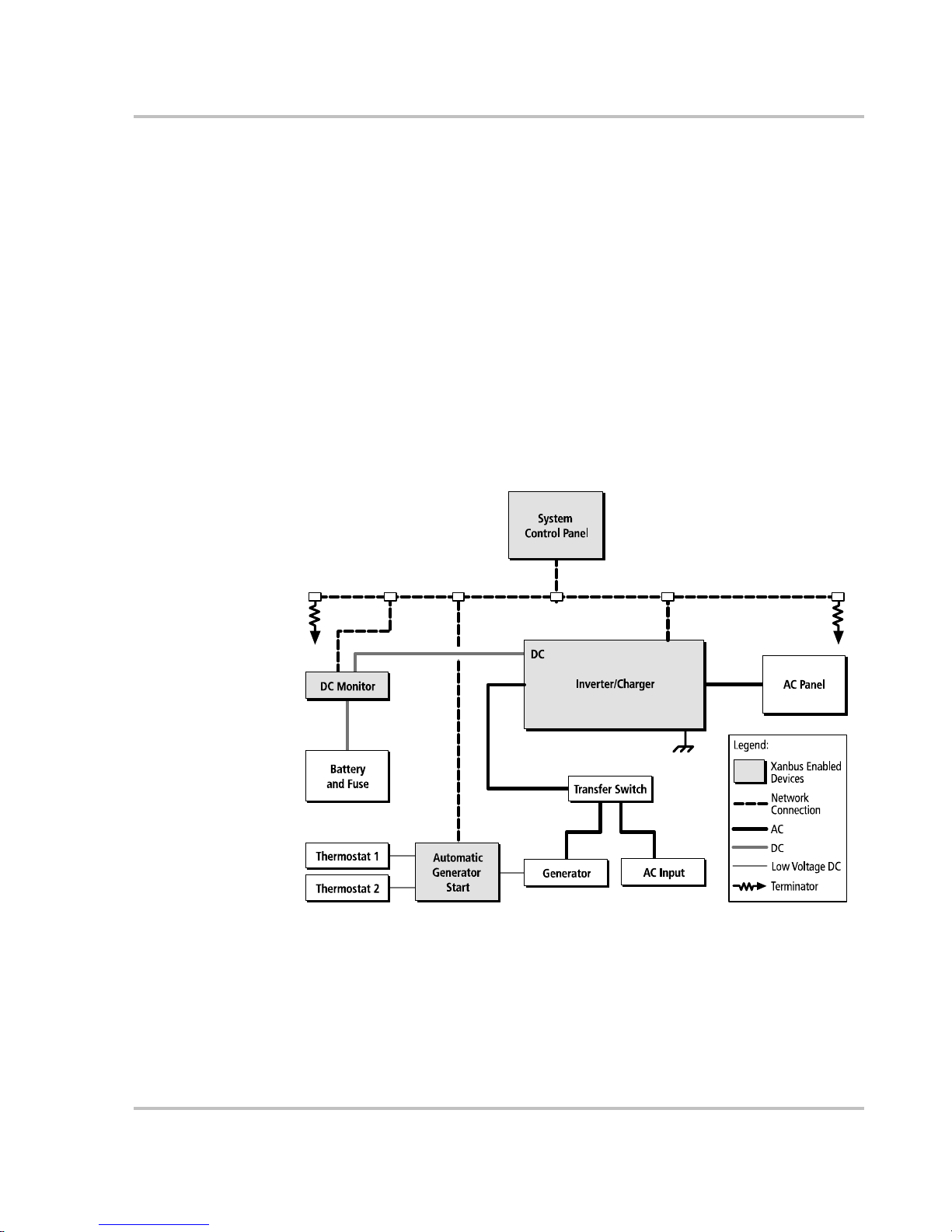
About the Xanbus System
The Xanbus system includes the RS2000 Sine Wave Inverter/Charger and other
Xanbus-enabled devices, as shown in Figure 1, “Typical Xanbus System
Diagram”. Each Xanbus-enabled device interacts and communicates with the
other devices on the network, creating a power system that can be precisely
configured to your needs.
The RS2000 is the device that typically provides power in a Xanbus system. The
System Control Panel provides configuration and monitoring capability for each
device connected to the Xanbus system, such as the Automatic Generator Start
and the RS2000.
In Figure 1, network connections are represented by dotted lines and conventio nal
electrical connections are represented by solid lines. Your system requirements
may be more complex than the basic installation shown in Figure 1. Xantrex
recommends that you consult a qualified installer or electrican to customize your
installation to meet your requirements.
Figure 1
Typical Xanbus System Diagram
AC In
AC Out
Page 22

Installation
4 975-0126-01-01
Xanbus Enabled
The Xanbus-enabled designation means that this product will work on a Xanbus
network. Xanbus-enabled products are:
• Easy to use. The Xanbus network simplifies operation and automates routine
tasks.
• Reliable. Software control eliminates errors due to analog signalling.
• Accurate. Digital information is less susceptible to interference and line loss.
• Upgradeable. Firmware upgrades mean your purchase will remain up to date.
For detailed instructions and a complete list of Xanbus-enabled devices, visit the
website at
www.xantrex.com
System Accessories
System accessories currently available which are Xanbus-enabled include the
System Control Panel and Automatic Generator Start. These system accessories
are available from any authorized Xantrex dealer or at
www.xantrex.com Please
provide the part number of the accessory to the dealer.
Other Xanbus-enabled devices will become available in the future.
Page 23

Installation
975-0126-01-01 5
Planning the Installation
This section provides information to help you plan for a basic installation of the
RS2000.
As your system configuration is determined, record the details in Information
About Your System on page WA-4 of the
RS2000 Sine Wave Inverter/Charger
Operation Guide
.
Two Key Performance Factors
Two key factors in particular will have a major impact on system performance.
Size and Length of DC Cables
To select the appropriate size and length of DC cables, see “DC Cabling” on
page 11.
The DC cables should be as short as possible and large enough to handle the
required current, in accordance with the electrical codes or regulations applicable
to your installation. If there are long battery cables which are in excess of 10 feet
each (10 feet for the positive cable and 10 feet for the negative cable) and not of
sufficient size, the voltage drop across the cables will have a negative impact on
overall system performance.
Mounting Location of the RS2000
To choose an appropriate location for mounting the inverter/charger, see
“Step 1: Choosing a Location for the Inverter/Charger” on page 17.
Page 24

Installation
6 975-0126-01-01
Planning
AC, DC, and Network Components
For a successful installation, you need to plan for AC, DC, and network
components of the power system. The AC and DC components are described in
this section and illustrated in Figure 2, “Typical Recreational Vehicle Electrical
System” on page 7.
AC components include:
• Sources of AC input
•AC wiring
• Over-current protection and disconnect devices
• AC distribution panels
DC components include:
• Sources of DC power
• DC cables
• DC over-current protection and disconnect devices
Network considerations include:
• Cables, connectors, network connectors, and terminators for the System
Control Panel and Automatic Generator Start, if installing. See Figure 1.
Detailed information on planning and installing your network is available in
the
Xanbus System Installation Guide. Refer to the system guide to determine
the type of network layout to install, as well as guidelines for installing the
network. This guide is available for download at
www.xantrex.com
Page 25

Installation
975-0126-01-01 7
Figure 2
Typical Recreational Vehicle Electrical System
Important:
In Figure 2, “Typical Recreational Vehicle Electrical System” on page 7,
no attempt has been made to show all required grounding or overcurrent protection.
Low Voltage DC
Xanbus-enabled
Devices
Generator
Isolator
Non-Inverter Loads
Automatic Generator Start System Control Panel
Sine Wave Inverter/Charger
Engine Battery
Transfer Switch
AC Main Pane l
AC In
AC Out
DC +
DC -
DC Fuse
House Battery
Battery Temperature
Sensor
UtilityPower
Inverter AC Panel
Alternator
RESET
TEST
Page 26

Installation
8 975-0126-01-01
AC Components
AC Input
A source of 120 volts AC single-phase, 60 Hz alternating current is needed to
provide energy for charging batteries and to pass through to AC loads. AC input
can be supplied from an AC source like the utility grid (power company), from a
generator, or from the output of a transfer switch. These sources must have their
neutral conductors bonded to ground. See “AC Output Neutral Bonding” on
page 9.
Disconnect and Over-Current Protection Device
T o meet CSA, UL, and electrical code requirements, the AC inputs and outputs of
the inverter/charger must be provided with over-current protection such as a
circuit breaker or fuse and a disconnect device on both the AC input and output.
Refer to your applicable installation codes and the following requirements:
AC Input Protection
The circuit breaker or fuse used to protect the RS2000 must be rated no more than
30 amps and must be approved for use on 120 VAC branch circuits. If the AC
input power rating is more than 30 amps, you need to add an additional 30 amp
breaker or fuse at the electrical panel to which the RS2000 AC input is wired.
AC Output
The circuit breaker or fuse must be rated at no more than 30 amps and must be
approved for use on 120 VAC branch circuits.
GFCI Requirements
A GFCI (ground fault circuit interrupter) is a device that deenergizes a circuit
when a current to ground exceeds a specified value that is less than that required
to blow the circuit breaker. GFCIs are intended to protect people from electric
shocks and are usually required in wet or damp locations.
Installation in recreational vehicles requires GFCI protection of certain branch
circuits. Consult all applicable codes.
Tested GFCIs
Compliance with UL standards requires that Xantrex test and recommend specific
GFCIs for use on the output of the inverter. Table 1 lists models that have been
tested and will function properly when connected to the AC output of the RS2000.
Table 1
Tested G FCI Models
Manufacturer Model Number
Hubbell GFR5252WA
Page 27

Installation
975-0126-01-01 9
Disconnect Devices
Each system requires a method of disconnecting the AC circuits. If the overcurrent protection device is a circuit breaker, it will also serve as the disconnect. If
fuses are used, separate AC disconnect switches will be needed ahead of the fuses.
Distribution Panels
Some systems incorporate distribution panels both ahead of the inverter/charger
(the AC source panel) and between the inverter/charger and the loads (the AC
load panel). AC source panel includes a main circuit breaker, which serves as
over-current protection for the panel. Additional circuit breakers serve individual
circuits, one of which serves the inverter/charger.
AC Wiring
Definition AC wiring includes all of the wires and connector s between the AC source an d the
inverter/charger input and all of the output wiring between the inverter/charger
and the AC load panels, circuit breakers, and loads.
Type The type of wiring required varies according to the electrical codes or regulations
applicable to your installation. For RV applications, this may be solid wire in
multi-conductor cables, but stranded wire is required if single conductors are
used. All wiring must be rated 90 °C or higher.
Size Wire size has to be coordinated with the overcurrent protection provided ahead of
the wire involved, in accordance with the electrical codes or regulations
applicable to your installation. The wiring used between the AC input circuit
breaker and the inverter/charger input must be sized to match the input breaker
rating. The wiring used between the AC output of the inverter/charger and the AC
output breaker must also be sized to match the input breaker rating. The wiring
used between the AC output breaker and your loads must be size d to match the
output breaker. Typically, No. 10 AWG is required for the 30A breakers required
to be on the RS2000 input and output.
AC Output Neutral Bonding
Bonding system The RS2000 provides a system that automatically connects the neutral conductor
of the inverter’s AC output circuit to safety ground (“bonding” it) during inverter
operation, and disconnects it (“unbonding” it) when the inverter/charger is
connected to external AC or generator power . Th is system is design ed t o confo rm
to installation codes that require single-phase AC sources such as inverters and
generators to have their neutral conductors tied to ground at the source of power in
Leviton 8599-GY
Pass & Seymour 1594-W
Table 1
Tested G FCI Models
Manufacturer Model Number
Page 28

Installation
10 975-0126-01-01
the same way that the neutral conductor from the utility is tied to ground. These
same codes specify that the neutral can only be connected to ground in one place
at any one time.
Suitability This automatic neutral-to-ground bonding system is suited for installations in
which the AC input source is known to have a bonded neutral. This will be the
case in most situations: in a utility feed, at an external AC hook-up, or a generator
with a bonded neutral. If not, have an electrician look into bonding the source’s
neutral to ground. See also “AC Input and Output Isolation” on page 21.
Page 29

Installation
975-0126-01-01 11
DC Components
Batteries
The RS2000 system requires a 12 volt, lead-acid deep-cycle battery or group of
batteries to provide the DC current that the inverter/charger converts to AC power .
The battery may be a flooded, gel, or AGM type.
For general information about batteries, see “Battery Information” on page 39.
For detailed information about specific brands of batteries, you’ll need to consult
individual battery manufacturers for this information.
DC Disconnects and Over-Current Device
The DC circuit from the battery to the inverter/charger must be equipped with a
disconnect and over-current device. (Refer to your applicable installation code.)
This usually consists of a circuit breaker, a “fused-disconnect,” or a separate fuse
and DC disconnect. Do not confuse AC circuit breakers with DC circuit breakers.
They are not interchangeable. The rating of the fuse or breaker must be matched
to the size of cables used in accordance with the applicable installation codes. The
breaker or fuse and disconnect should be located as close as possible to the battery
in the positive cable.
Applicable codes may limit how far the protection can be
from the battery.
DC Cabling
DC cabling includes all of the cables and connectors between the batteries, the DC
disconnect and over-current protection device, and the inverter/charge r . All
installations require multi-strand insulated cables as well as disconnect and overcurrent devices. DC cable sizes are indicated by AWG notation. Under the AWG
standard, a larger gauge number indicates a smaller size diameter. Wire size is
usually marked on the cables for sizes this large.
See T able 2 for required DC cable size and required fuse size for the RS2000.
The
DC cables must be copper and must be rated 90 °C minimum.
Important:
Avoid excessive cable lengths to ensure optimum system
performance.
Table 2
Required DC Input Cable (copper) and Fuse Size
Maximum DC Cable
Length: Battery to
Inverter/Charger
(one way)
T otal Length (two
way)
Minimum
Recommended
Cable Size
Maximum
Battery Fuse or
Breaker
10 feet
(3 meters)
20 feet
(6 meters)
No. 4/0 AWG 300A class T
Page 30

Installation
12 975-0126-01-01
DC Grounding
The inverter/charger DC (chassis) ground terminal needs to be connected to the
vehicle chassis by a minimum No. 8 AWG copper conductor, which is either rated
90 °C or is bare copper.
Page 31

Installation
975-0126-01-01 13
Unpacking and Inspecting the Inverter/Charger
Materials List
Contents The following materials are in the shipping box:
• RS2000 Sine Wave Inverter/Charger
• Battery terminals covers (one red, one black) and four screws
•Two flat washers
• Two lock washers
• Two 3/8" bolts
• Battery temperature sensor
• RS2000 Sine Wave Inverter/Charger Installation Guide (not shown)
• RS2000 Sine Wave Inverter/Charger Operation Guide (not shown)
To unpack and inspect:
1. Unpack the unit and check the materials list. If anything is missing from the
shipping box, contact Xantrex Customer Service. See “Contact Information”
on page iii.
2. Record the serial number of the RS2000 and other purchase information in the
“Warranty and Product Information” section of the
RS2000 Sine Wave
Inverter/Charger Operation Guide
. You will be asked for this product
information if you need to call Xantrex Customer Service.
WARNING: Heavy load
The RS2000 Sine W ave Inverter/Charger weighs approximately 67 lbs (30 kg). The unit is
too heavy for one person to safely lift and mount. Xantrex recommends that two people
lift and mount the unit. Always use proper lifting techniques during installation to prevent
personal injury.
Figure 3
RS2000 Hardware Materials as Shipped
Page 32

Installation
14 975-0126-01-01
3. Save your purchase receipt to use as proof-of-purchase, especially for
warranty service. This is required if the inverter/charger should need warranty
service.
4. Save the original shipping carton and packing materials. If the inverter/
charger needs to be returned for service, it should be shipped in the original
carton. This is also a good way to protect the inverter/charger if it ever needs
to be moved.
Page 33

Installation
975-0126-01-01 15
Installation Tools and Materials
Tools You will need the following tools to install the RS2000 and the battery
temperature sensor.
❐ Wire stripper
❐ Crimping tools for fastening lugs and terminals on DC cables
❐ Phillips screwdriver: #2
❐ Slot screwdriver (¼" wide blade max.)
❐ Needle-nose pliers
❐ Wrench for DC terminals: 9/16"
Materials You will need the following materials to complete your installation:
❐ Strain-relief clamp (s) for AC cables
❐ DC battery cables
❐ Terminals and/or crimp connectors for DC cables
❐ AC and DC disconnect switches and over-current protective devices and
connectors as required
❐ Copper wire for DC grounding: No. 8 AWG
❐ Cables for AC output and input wiring
❐ Six ¼"–20 1.25" length steel screws or bolts to mount the RS2000
For a list of tools and materials required to install the network, refer to the
Xanbus
System Installation Guide,
which is available for download at www.xantrex.com.
Page 34

Installation
16 975-0126-01-01
Installing the Inverter/Charger
Overview
This section provides detailed information on installing the RS2000. The overall
procedure is divided into eight steps:
1. Choosing a location
2. Mounting the inverter/charger
3. Connecting the AC input wires and AC output wires
4. Connecting the DC cables
5. Connecting the battery temperature sensor
6. Connecting to the network
7. Performing checks prior to initial start-up
8. Testing your installation
Page 35

Installation
975-0126-01-01 17
Step 1: Choosing a Location for the Inverter/Charger
The location of the inverter/charger is a key factor in system performance.
Allow sufficient clearance around the unit and install in a well-ventilated
compartment to prevent overheating and premature shutdown of the inverter/
charger.
The inverter should only be installed in a location that meets the following
requirements:
WARNING: Risk of fire or explosion
This equipment contains components that could produce arcs or sparks. To reduce the risk
of fire or explosion, do not install this equipment in compartments containing batteries or
flammable materials, or in locations that require ignition-protected equipment. This
includes any space containing gasoline-powered machinery, fuel tanks, or joints, fittings,
or other connections between components of the fuel system.
WARNING: Fire hazard
Do not cover or obstruct the ventilation openings. Do not install this equipment in a
compartment with limited airflow. Overheating may result.
Ventilated Do not operate the inverter/charger in a closed-in area or
restrict ventilation in any way. The inverter/char ger requires
air circulation to maintain optimum operating temperature
and provide best performance. If the unit has inadequate
ventilation, it may shut down due to overheating.
The air vented through the openings should also have a path
to circulate away from the inverter/charger.
Dry Do not allow water or other fluids to drip or splash on the
inverter. Do not expose to rain, snow or water.
Cool Normal air temperature should be between 32 °F and
122 °F (0 °C and 50 °C – the cooler the better within this
range.)
Clearance Allow as much space around the inverter/charger as
possible. Xantrex recommends that other objects and
surfaces be at least 3 inches (76 mm) away from the
ventilation openings for best performance.
Safe Locate the inverter/charger away from battery in a separate
well ventilated compartment. Do not install the inverter/
charger in any compartment containing flammable gases or
liquids like gasoline.
Page 36

Installation
18 975-0126-01-01
Close to
battery
compartment
The length and size of your DC cables will affect
performance. Use the DC cables recommended in Table 2
on page 11. The unit should not be installed in the battery
compartment due to the possible presence of explosive
hydrogen gas from the batteries.
Protected
from battery
acid and gases
Never place the inverter/charger directly above the
batteries—gases from battery will corrode and damage the
inverter/charger. Never allow battery acid to drip on the
inverter/charger or its wiring when filling the batteries or
reading their specific gravity.
Orientation To meet regulatory requirements, the RS2000 must be
mounted in an approved mounting orientation. See Figure 4
on page 20.
Page 37

Installation
975-0126-01-01 19
Step 2: Mounting the Inverter/Charger
Considerations
Before mounting the RS2000, take the following two factors into account.
1. The weight of the inverter/charger requires two people to install it.
2. Mounting considerations are shown in Figure 4 on page 20 and described in
Table 3 on page 20.
The RS2000 dimensions and location of the mounting holes are provided in
Figure 15 on page 38.
Mount your inverter/charger before you connect any wires or cables.
To mount the inverter/charger:
1. Remove the inverter/charger from its shipping container.
The inverter/charger is shipped on a packaging board which can also serve as
a template.
2. Remove the four screws that attach the inverter/charger to the packaging
board. Use the box handles provided to move the unit.
3. Verify that all components are present, and record relevant product
information on form WA-4 in the
RS2000 Sine Wave Inverter/Charger
Operation Guide.
4. Select an appropriate mounting location and orientation. To meet regulatory
requirements, the RS2000 must be mounted in one of the six orientations
shown in Figure 4.
5. Use the packaging board as a template to mark the position of the mounting
screws or refer to Figure 15 on page 38.
6. Pilot drill the six mounting holes.
7. Fasten the inverter/charger to the mounting surface with the six ¼"–20 steel
screws or bolts.
WARNING: Heavy load
The RS2000 Sine W ave Inverter/Charger weighs approximately 67 lbs (30 kg). The unit is
too heavy for one person to safely lift and mount. Xantrex recommends that two people
lift and mount the unit. Always use proper lifting techniques during installation to prevent
personal injury.
Important:
Do not use the four screws which attach the unit to the template for
mounting the unit. See “Installation Tools and Materials” on page 15 for recommended
screw size.
Page 38

Installation
20 975-0126-01-01
Figure 4
Approved Mounting Orientations
Table 3
Description of Approved Mounting Orientations
Number Approved Mounting Orientation
1Desktop
2 Upside-down mount—this orientation is suitable only for applications with no risk of
condensation or dripping water.
3 Wall mount orientation— on a vertical surface with DC terminals facing down.
4 Wall mount orientation—on a vertical surface with DC terminals facing right.
5 Wall mount orientation—on a vertical surface with DC terminals facing up. This
orientation is suitable only for applications with no risk of condensation or dripping
water.
6 Wall mount orientation—on a vertical surface with DC terminals facing left.
1 - Desktop mount
2 - Upside-down mount - only
for applications with no risk
of condensation or dripping water
3 - Wall mount
4 - Wall mount
6 - Wall mount
5 - Wall mount - only for applications with
no risk of condensation or dripping water
?
?
Page 39

Installation
975-0126-01-01 21
Step 3: Connecting the AC Input and AC Output Wires
General AC Wiring Considerations
AC and DC Wiring Separation Do not mix AC and DC wiring in the same
conduit or panel. Consult the applicable installation code for details about DC
wiring and AC wiring in vicinity to each other.
AC Input and Output Isolation The AC input and output circuits of this
inverter/charger are isolated from each other when in invert mode to ensure safe
operation. This isolation must be maintained in the installation, by being sure not
to connect AC input and output wiring to a common point. For example, do not
route the AC input and output neutrals to a common neutral bus.
AC Wiring Compartment For your reference, the AC wiring compartment is
shown in Figure 5.
AC Knockouts There are two 3/4" trade-size knockouts on the front panel for
AC wiring, as shown in Figure 5. For easier wiring access, there are also
knockouts on either side of the unit (not shown). The side knockouts are 1" tradesize knockouts. Use the same trade size of strain relief as the trade size of the
knockout (s) you are using.
AC Wiring Terminals The AC wiring terminals accepts cables of a specific
size. See “Cables for AC output and input wiring” on page 15 for required sizes.
WARNING: Fire, shock, and energy hazards
Make sure wiring is disconnected from all electrical sources before handling. All wiring
must be done in accordance with local and national electrical wiring codes.
Figure 5
Front Panel with Wiring Compartment
Page 40

Installation
22 975-0126-01-01
Connecting AC Input Wires
A detailed view of the RS2000 wiring compartment with the AC compartment
panel removed is shown in Figure 6. The terminal block is used to hardwire the
AC input and AC output connections.
When making the AC input and AC output connections, observe the correct
colour code for the appropriate AC wire, as described in Table 4.
To make the AC input connections:
1. Locate the wiring compartment cove r pan el and rem ov e the four screw s .
2. Remove the cover panel from the unit to access the wiring compartment.
3. Remove one of the AC knockouts from the front or side of the unit using a
slot screwdriver. Do not leave the knockout inside the wiring compartment.
4. Install a strain-relief clamp in the AC knockout.
5. Run the AC wiring through the strain-relief clamp.
6. Strip approximately 2 inches (50 mm) off the jacket from the AC cable and
separate the three wires.
7. Using the slot screwdriver, loosen the wire attachment screws on the
terminals. Do not remove the screws.
8. Insert the line wire into "L", the neutral wire into "N", and the ground wire
into ground , as shown in Figure 6 on page 23 . Observe the colour codes
described in Table 4.
9. Tighten the wire attachment screws. Leave some slack wire inside the wiring
box.
10. Secure the strain-relief clamp on the AC input cable jacket.
CAUTION: Equipment damage
The terminal block is split into INPUT and OUTPUT sections. Damage may occur if the
unit is wired incorrectly .
Do not remove or loosen factory installed wiring.
Table 4
Colour Codes for Typical AC Wiring
Colour AC Wire
Black Line
White Neutral
Green or bare copper Ground
Page 41

Installation
975-0126-01-01 23
Connecting the AC Output Wires
To make the A C output wiring connections:
1. Remove one of the AC knockouts from the front or side of the unit using a
slot screwdriver. Do not leave the knockout inside the wiring compartment
2. Install a strain-relief clamp in the AC knockout.
3. Run the AC wiring through the strain-relief clamp.
4. Strip approximately 2 inches (50 mm) off the jacket from the AC cable and
separate the three wires..
5. Using an appropriate sized slot screwdriver, loosen the wire attachment
screws on the AC output terminals. Do not remove the screws.
6. Insert the line wire into "L", the neutral wire into "N", and the ground wire
into ground , as shown in Figure 6. Observe the colour codes described in
Table 4.
7. Tighten the wire attachment screws. Leave some slack wire inside the wiring
box.
8. Secure the strain-relief clamp on the AC output cable jacket.
9. Attach the wiring compartment cover panel and tighten the four screws.
10. Connect the outgoing AC wires to an AC load panel equipped with circuit
breakers.
Figure 6
AC In and AC Out: Hardwiring Completed
CAUTION: Risk of equipment damage
Do not connect the output of the inverter to any incoming AC source.
Important:
The applicable installation code may not allow you to run the AC
input and AC output wiring through the same AC knockout.
Page 42

Installation
24 975-0126-01-01
Step 4: Connecting the DC Cables
DC Connection Precautions
Connect and disconnect DC wiring only after opening the disconnect switches or
breakers at all AC and DC sources.
Recommended Cable Sizes and Lengths and Fuse Size
For the best load starting surge performance, the DC cables should be as short as
possible and large enough to handle the required current, in accordance with the
electrical codes or regulations applicable to your installation. Avoid excessive
cable lengths.
The DC cables must be copper and must be rated 90 °C
minimum.
For recommended DC cables and fuse size, see Table 2, “Required DC Input
Cable (copper) and Fuse Size” on page 11.
Using a longer or smaller gauge cable
may cause the inverter to shut down under heavy load.
Preparing the Cables
To prepare the DC cables:
1. Cut the negative cable to the required length. Strip off enough insulation so
you can install the terminals you will be using.
Xantrex recommends the use of crimp connectors. The connector should be
designed for a 3/8" stud size to connect to the RS2000. If a crimp connector is
used, it should be crimped using the tool indicated by the connector
manufacturer.
2. Cut the positive cable to the required length. Strip of f enough insulation so
you can install the terminals you will be using.
3. Attach the connectors to the ends of both cables. Make sure no stray wire
strands protrude from the connectors.
Page 43

Installation
975-0126-01-01 25
Guidelines for Routing the DC Cables
Follow these guidelines to ensure maximum performance.
• Do not attempt to use the chassis in place of the battery negative connection
for grounding. The inverter requires a reliable return path directly to the
battery.
• To reduce the chance of radio frequency interference, keep the positive and
negative cables close together—ideally, held together by straps or loom or
insulated clamps at regular intervals.
• To ensure maximum performance from the inverter, do not route your DC
cables through a DC distribution panel, battery isolator, or other device that
will cause additional voltage drops. The exception is the DC fuse and
Disconnect or the DC circuit breaker which is required at the battery to
protect the DC wiring.
• To help avoid damage caused by reverse polarity battery connection, it is a
good idea to mark each end of each cable to identify it as a positive (red) or
negative (black) cable before routing the wiring.
WARNING: Fire and shock hazard
Route the cables away from sharp edges that might damage the insulation. Avoid sharp
bends in the cable.
Page 44

Installation
26 975-0126-01-01
Connecting the DC Cables to the Inverter/Charger
To connect the DC cables:
1. Route the DC cables from the battery bank to the inverter/charger. Observe
the “Guidelines for Routing the DC Cables” on page 25.
2. Install a DC fuse and disconnect switch or a DC circuit breaker between the
inverter/charger and the battery. They must be installed in the positive side of
the DC circuit, as close as possible to the battery.
This protects your battery and wiring in case of accidental shorting. See
Table 2 on page 11 for required fuse or breaker size. Open the DC disconnect
switch or turn off the DC circuit breaker.
3. Connect one connector on the POSITIVE (+) cable to the POSITIVE DC
terminal on the inverter/charger, as show n in Figure 7. The connector goes on
first, then the flat washer (steel), lock washer (steel), and 3/8" bolt (brass)).
4. Connect the other connector to the POSITIVE (+) terminal on the fuse or
breaker. Observe polarity carefully while completing the installation.
Use a wrench to tighten the bolt to a torque of 15–16 ft-lbs (20.4–21.7 Nm) at
the inverter/charger end. Observe the fuseholder or breaker manufacturer’s
recommendation at the other end.
5. Connect one connector on the NEGATIVE (–) cable to the NEGATIVE (–)
DC terminal on the inverter/charger, as shown in Figure 7. The connector
goes on first, then the flat washer (steel), lock washer (steel), and 3/8" bolt
(brass)).
WARNING: Fire hazard
Use only appropriately sized copper cable. Loose connections or improper connections
will overheat. Make sure the bolts supplied by Xantrex on the inverter/charger are
tightened to a torque of 15–16 ft-lbs (20.4–21.7 Nm). Torque all other connections to the
manufacturer’s specifications. Make sure the DC cable, washers, and bolt are assembled
in the order shown in Figure 7.
CAUTION: Reverse polarity damage
Before making the final DC connection or closing the DC breaker or disconnect, check
cable polarity at both the battery and the inverter/charger. Positive (+) must be connected
to positive (+). Negative (–) must be connected to negative (–).
Page 45

Installation
975-0126-01-01 27
6. Before proceeding, check that the cable polarity is correct: POSITIVE (+) on
the inverter/charger is connected to the POSITIVE (+) on the battery, and
NEGATIVE (–) cable is connected to the NEGATIVE (–) terminal on the
inverter/charger.
7. Connect the other end of the cable to the NEGATIVE (–) terminal on the
battery.
8. Use a wrench to tighten the bolt to a torque of 15–16 ft-lbs (20.4–21.7 Nm
) at
the inverter/charger
end.
9. Attach the DC terminal covers using the screws provided to protect the DC
terminals, as shown in Figure 8.
The completed DC terminal wiring with covers is shown in Figure 9.
Figure 7
DC Cable Connections
Important:
The next step is the last cable connection you need to make. A spark is
normal when this connection is made.
Figure 8
DC Te rminal Covers
Page 46

Installation
28 975-0126-01-01
DC Grounding
The Chassis Ground point on the inverter/charger is used to connect the chassis of
the inverter/charger to your system’ s DC grounding point, as required by
regulations for some installations. Use copper wire that is either bare or provided
with green insulation.
The grounding guideline given below assumes you are using the code-compliant
DC supply cable and fuse sizes indicated in this Installation Guide. If you are
using different sizes, refer to the applicable code for DC grounding detail.
To connect the chassis ground:
1. Using the appropriate screwdriver, loosen the screw on the chassis ground
point shown in Figure 9.
2. Connect a No. 8
AWG copper cable between the chassis ground point and the
DC grounding point for your system.
In an RV or vehicle installation, this will usually be the vehicle chassis or a
dedicated chassis ground bus.
3. Tighten the screw to a torque of 1.0–1.25 ft-lbs (1.47–1.7 Nm).
Figure 9
Completed DC Wiring and DC Grounding
!
chassis ground
point
Page 47

Installation
975-0126-01-01 29
Step 5: Connecting the Battery Temperature Sensor (BTS)
Installing a battery temperature sensor extends the life of a battery by preventing
overcharging in warm temperatures and undercharging in cold temperatures. W ith
a BTS monitoring the battery temperature, the voltage delivered to the battery is
adjusted according to battery’s actual temperature.
The BTS has a self-adhesive backing and attaches to the side of the battery. A
25-foot (7.6 m) cable is supplied with the BTS, as shown in Figure 10.
Mounting Options
You can mount the battery temperature sensor (BTS) in one of two ways:
• Mounting the sensor to the negative battery post allows the internal battery
temperature to be sensed and provides the most accurate results.
• Attached the sensor to the side of battery using the self-adhesive backing also
provides good results in most situations.
Figure 10
BTS with Cable
WARNING: Energy and explosion hazard
Review the “Important Safety Instructions” on page v.
Page 48

Installation
30 975-0126-01-01
Mounting to the Negative Battery Terminal
To mount the sensor on the negative battery terminal:
See Figure 11.
1. Select the battery to be monitored. The battery temperature sensor should be
connected to the battery bank that is directly connected to the inverter/charger .
2. Switch off all devices operating from the battery, or open battery switch if
present to disconnect battery.
3. Wait 10 minutes for any explosive battery gases to dissipate.
4. Remove the nut that connects existing wiring ring terminals to the battery
negative terminal stud.
5. Move or reorient the existing wiring ring terminals on the battery negative
terminal stud, so there is a flat surface on which to seat the battery
temperature sensor mounting plate.
Y o u may need to bend the ring terminal crimp and/or wires slightly downward
to allow the sensor to seat flush to the top surface of the upper ring terminal.
6. Mount the sensor directly on top of the ring terminal, as shown in Figure 11,
and firmly tighten the terminal nut.
7. Check to ensure that the sensor and all wires are held firmly and cannot be
moved.
8. Turn the battery switch on again (if you opened it in Step 2.)
9. Route the sensor cable to the inverter/charger and plug it into the Battery
Temp jack, as shown in Figure 12. Secure the cable along its length.
Figure 11
BTS Mounted on the Negative Battery Terminal
WARNING: Fire hazard
In this procedure, you must install the DC wire on the battery terminal first. Then the
sensor is installed on top of the DC wire. This sequence is required to provide the best
connection to the battery and to ensure correct performance of the sensor.
Page 49

Installation
975-0126-01-01 31
Figure 12
Connecting the BTS Cable to Battery Temp. jack
Page 50

Installation
32 975-0126-01-01
Mounting to the Side of the Battery Case
To mount the sensor on the battery case:
See Figure 13.
1. Select the battery to be monitored.
The battery temperature sensor should be connected to the battery bank that is
directly connected to the inverter/charger.
2. Select a side suitable for attaching the sensor.
The surface where the sensor is to be mounted must be flat and free from
reinforcing ribs or other raised features. This surface must be in direct internal
contact with the battery electrolyte. Do not install the sensor near the top of
the battery or on the battery’s top surface.
3. Clean the selected area thoroughly to remove any oil or grease that could
prevent the sensor from adhering to the battery case and allow the battery cas e
to dry thoroughly.
4. Peel the protective backing from the self-adhesive strip on the rear of the
sensor.
5. Press the sensor firmly against the clean side of the battery to fix it in place, as
shown in Figure 13.
6. Route the sensor cable to the inverter/charger and plug it into the Battery
Temp. jack, as shown in Figure 12. Secure the cable along its length.
Figure 13
BTS Mounted on the Battery Case
Page 51

Installation
975-0126-01-01 33
Step 6: Connecting to the Network
For your reference, Figure 14 shows where the network connections are made on
the RS2000.
Detailed information on planning and installing your network is available in the
Xanbus System Installation Guide. Refer to the this guide to determine the type of
network layout to install, as well as guidelines for installing the network.
The Xanbus System Installation Guide is available for download at
www. xantrex.com
CAUTION: Equipment Damage
Connect the RS2000 only to other Xanbus compatible devices.
Although the cabling and connectors used in this network system are the same as Ethernet
connectors, this network is not an Ethernet system. Equipment damage may result from
attempting to connect two different systems.
Figure 14
Connecting to a Network Jack
Page 52

Installation
34 975-0126-01-01
Step 7: Performing Checks Prior to Initial Start-Up
Before testing your installation, ensure these conditions are met:
❐ Chassis and AC grounds are properly installed.
❐ AC input connections and AC output connections are wired correctly on the
terminal block and not reversed.
❐ Positive (+) battery cable is connected to the positive (+) battery terminal
through the DC fuse and disconnect switch or DC circuit breaker.
❐ Negative (–) battery cable is connected to the negative (–) battery terminal.
❐ Battery voltage is within the proper range for this unit
(10.3–15.3 volts DC).
❐ DC disconnect switch or breaker is turned off.
❐ AC input and output breakers are turned off.
❐ All connections are tight.
Page 53

Installation
975-0126-01-01 35
Step 8: Testing Your Installation
There are three tests to be performed for testing your installation. The first test
verifies that the RS2000 works in invert mode. The second test verifies that the
RS2000 works in charge mode. The third test verifies that the RS2000 works in
AC bypass mode.
Testing in Invert Mode
To test the inverter/charger in invert mode, using a 100 watt light bulb as the
test load:
1. Close the DC disconnect switch or the DC circuit breaker to supply DC power
to the RS2000.
The unit takes 10 to 30 seconds to initialize. After 10 to 30 seconds, normal
indicator lights illuminate on the front panel.
2. Verify that all lights illuminate. Only the Inverter On light stays illuminated.
3. Close the AC output breaker to connect the RS2000 to the load or load panel.
The light bulb is illuminated.
Testing in Charge Mode
To test the RS2000 in charge mode:
1. Close the AC supply breaker to supply AC power to the unit.
2. After a few seconds, verify that the Bulk light illuminates. Over a period of
time, the Absorption or Float light illuminates as charging progresses.
• In three-stage charging, the Bulk, Absorption and Float lights illuminate
in sequence.
• In two-stage charging, the Bulk and Absorption lights illuminate in
sequence.
WARNING: Shock hazard
The Inverter Enable button on the RS2000 and the optional accessories do not disconnect
DC or AC input power to the RS2000.
Important:
The charging process, whether it is three-stage or two-stage charging,
occurs over an extended period of time.
Page 54

Installation
36 975-0126-01-01
Testing in AC Bypass Mode
To test the RS2000 in transfer mode:
1. Close the AC circuit breaker supplying AC input power to the inverter.
The transfer from invert to AC input power occurs.
2. Press the Charger Enable button to disable the charger. Verify that the Charger
Enable light is not illuminated. AC loads will still be powered.
Page 55

Installation
975-0126-01-01 37
Inverter/Charger Specifications
For inverter/charger specifications, refer to the RS2000 Sine Wave Inverter/
Charger Operation Guide
.
Physical Specifications with Projections
The physical specifications of the RS2000 are shown in Figure 15 on page 38 and
described in Table 5.
Table 5
RS2000 Physical Specifications
Length 16.19 inches (411 mm)
Width 14.20 inches (361 mm)
Height 8.1 inches (208 mm)
Weight 67 lbs (30 kg)
Page 56

Installation
38 975-0126-01-01
Figure 15
Inverter/Charger Dimensions
Page 57

Installation
975-0126-01-01 39
Battery Information
“Battery Information” discusses the physical make-up and characteristics of
chemical storage batteries and will help you to understand the factors involved in
battery selection, charging, care, and maintenance. This information is a guideline
only. The manufacturer of each battery is the best authority on its use and care.
Page 58

Installation
40 975-0126-01-01
Terminology
A description of battery charger operation requires the use of terms that you may
not be familiar with. The following terms appear throughout the guide.
Deep Cycle A deep cycle occurs when a battery is discharged to less than 50%
of its capacity (50% depth of discharge). A deep-cycle battery is one that is
intended to be deeply discharged and charged repeatedly.
Depth of Discharge (DOD) The amount of energy or charge removed from the
battery bank, usually expressed as a percentage. A depth of discharge of 0%
indicates a fully-charged battery, and a depth of discharge of 100% indicates a
fully-discharged battery.
Electrolyte Typically sulfuric acid and water. It is commonly referred to as
battery acid, and it is the fluid inside a typical lead-acid battery.
Equalization A deliberate overcharge designed to reduce sulfation and
stratification in flooded (or wet) lead-acid batteries. Not necessary and harmful on
Gel or sealed batteries.
Plates Made of lead and connected to the battery terminals. These are the
terminals inside each cell of the battery. The essential chemical reactions of the
battery occur at the plates, and they are the source of the current/voltage produced
by the battery.
Sulfation As a battery discharges, its plates become covered with lead sulfate.
With regular recharging, the lead sulfate leaves the plates and recombines with the
electrolyte. If the lead sulfate remains on the plates for an extended period of time
(over two months), it hardens, and recharging does not remove it. Sulfation
reduces the effective plat e area a nd the bat tery’s capacity. Equa lization of flooded
(or wet) batteries helps to reduce sulfation.
Stratification Over time, electrolyte tends to separate. The electrolyte at the top
of the battery becomes watery while it becomes more acidic at the bottom. This
effect is corrosive to the plates. Equalization of flooded (or wet) batteries helps
reduce stratification.
Temperature Compensation Optimal battery charging voltage is dependent on
the temperature. As the ambient temperature falls, the proper voltage for each
charge stage needs to be increa se d . When the ambient temperature increases, the
proper voltage for each charge stage needs to be decreased. (The RS2000 battery
temperature sensor (BTS) automatically rescales charge-voltage settings to
compensate for ambient temperatures.) The hot, cold, and warm settings are used
if a battery temperature sensor is not present. The hot setting is the default.
Page 59

Installation
975-0126-01-01 41
Battery Types
For the purposes of this discussion, there are two principal types of batteries:
starting and deep-cycle. Batteries are either sealed or vented. However, there are
even different kinds of these batteries. This section explains some of the
differences among lead-acid batteries to help you choose a battery that best suits
your needs.
Your RS2000 Sine Wave Inverter/Charger is designed for use with deep-cycle,
lead-acid batteries. These batteries are designed for deep discharge service where
they will be repeatedly charged and discharged. This type of battery is often
labeled as a marine, recreational vehicle, or golf cart battery . Xantrex recommends
that you use one or more deep-cycle batteries separated from the starting battery
of your vehicle or boat.
Starting Batteries
Do not use starting batteries with your inverter; they will wear out rapidly in a
deep-cycle application. The way they are rated gives a good indication of their
intended use: “Cold Cranking Amps” is a measure of the amperage output of a
battery intended for starting or “cranking” an engine.
Starting batteries use many thin plates to maximize the surface area of the battery .
This allows very high starting current. In a deep cycle application, these batteries
will limit the number of cycles that can be supported before the battery needs to be
replaced.
Deep Cycle Batteries
Deep-cycle batteries are best suited for use with inverters. They are designed to
have the majority of their capacity used before being recharged. Available in
many sizes and types, the most common is the non-sealed, liquid electrolyte type
referred to as a “flooded (or wet)” battery , comm only used in both bo ats and RVs.
Non-sealed types have removable battery caps. The caps should be removed at
least monthly so the electrolyte level can be checked. When a cell is low, only
distilled water should be added. “Spring” water and regular tap water may have
high mineral levels which can poison the battery chemistry and reduce battery
life.
Deep-cycle, lead-acid batteries can be grouped into five categories:
• Flooded (or wet)
• Sealed flooded (“maintenance free”)
• Recombinant flooded (often “starved electrolyte”)
• Gel batteries
• AGM
Page 60

Installation
42 975-0126-01-01
Another popular and inexpensive battery of this type is the “golf cart”
(T -105 or CG220 or US 2200 ) battery . These six-volt batteries can be connected in
series to form a 12V system and can be discharged repeatedly to 80% of their
capacity without being severely damaged. This is the minimum quality of battery
that should be used with the inverter in normal applications.
Some systems use the L16 type of battery. These are 6-volt batteries rated at
350Ah and are available from a number of manufacturers. They are 17 inches (43
cm) high and weight up to 130 pounds (60 kg) each — which maybe be
troublesome in some installations.
Type 8D batteries are available in either cranking or deep-cycle construction. The
deep-cycle versions are 12-volt batteries rated at approximately 200 Ah. Since
they are mostly commonly used to start truck engines, you should make sure you
purchase the deep-cycle version, not the cranking version. Type 4D batteries are
very similar in construction but are somewhat smaller (approximately 170 Ah).
Sealed Gel-Cell
Another type of deep-cycle battery is the sealed gel-cell. The electrolyte is in the
form of a gel rather than a liquid and never requires topping up. Battery caps are
not removable. The sealed construction allows the batteries to be mounted in any
position without spilling. The advantages are no maintenance (to the battery itself
the system still requires routine maintenance), long life (800 cycles claimed), and
low self-discharge. The disadvantages are high initial cost and the possibility of
damage form overcharging.
While many manufacturers produce quality flooded (or wet) batteries, only a few
produce suitable gel-cells. Don’t confuse gel batteries with maintenance-free
batteries, which are typically standard flooded (or wet) electrolyte batteries
without caps for adding water, and when the electrolyte gets low, you replace the
battery.
AGM (absorbed glass mat) batteries are similar to gel-cells and deep-cycle types
and can be used in inverter applications.
Environment
For long life and good performance, batteries need to be located in a protected,
ventilated enclosure insulated from temperature extremes.
Location
Batteries should be located in an accessible location that allows for access to the
battery caps and terminals. At least twelve to eighteen inches of clearance above
the batteries is recommended. They must be located as close as possible to the
inverter/charger to keep the cable run short. However, do not locate the batteries
in the same space as the inverter/charger unless they are of the sealed gel-cell
type.
Page 61

Installation
975-0126-01-01 43
Enclosures
Batteries must be protected inside a ventilated enclosure. The enclosure should be
ventilated to the outdoors from the highest point to prevent the accumulation of
hydrogen gases released in the charging process. An air intake should also be
provided at a low point in the enclosure to allow air to enter the enclosure to
promote good ventilation.
Temperature
Effect of cold
temperature
The effective capacity of a battery is reduced when the temperature is cold. This
phenomenon is more significant with lead-acid type batteries than with alkaline
types. When the internal temperature of a lead-acid battery is 32 °F (0 ° C), the
capacity can be reduced by as much as 50%. This effectively reduces the size of
the system’s “gas tank,” requiring more frequent “refueling” by the charger. This
should be considered when you design the system. If extremely low temperatures
are expected where the system is going to be located, a heated equipment room
should be considered.
Benefits of
insulated enclosure
If the system is located in an unheated space, an insulated enclosure is highly
recommended for the batteries. During the charging process, the batteries release
heat due to the internal resistance of the battery. If the batteries are insulated, the
heat can be kept in the batteries to keep them warmer. This will substantially
increase the performance of the system.
Insulated battery enclosures also ensure that the temperatures of individual battery
cells are more consistent. This prevents unequal charging, which can cause battery
failure (some cells being overcharged while others are undercharged).
Protect batteries
from high
temperature
The batteries should also be protected from high temperature. This can be caused
by high ambient temperatures, solar heating of the battery enclosure , o r heat
released by an engine or generator located close by. High battery temperature
results in short battery life and should be avoided by ventilating the enclosure and
reducing the external heat sources by shading and insulation.
Page 62

Installation
44 975-0126-01-01
Battery Bank Sizing
Purchase as much
battery capacity as
possible
Battery size or capacity is just as important as the battery type selected for use
with your RS2000 Sine Wave Inverter/Charger. The batteries are the most
important part of your system, so Xantrex recommends that you purchase as much
battery capacity as possible. A large battery will extend running time and ensure
that your inverter/charger delivers full rated surge. Your inverter/charger can be
configured to work with batteries from 50 Ah (120 reserve minutes) to 2000 Ah
(4800 reserve minutes).
Battery capacity A number of different standards are used to rate battery energy storage capacity.
Automotive and marine starting batteries are normally rated in cranking amps.
This is not a relevant rating for continuous loads like an inverter. Deep-cycle
batteries use a more suitable rating system, either amp-hours (Ah) or “reserve
capacity” in minutes. Battery reserve capacity is a measure of how long a battery
can deliver a certain amount of current—usually 25 amps.
For example, a battery with a reserve capacity of 180 minutes can deliver 25 amps
for 180 minutes before it is completely discharged. Amp-hour capacity is a
measure of how many amps a battery can deliver for a specified length of time,
usually 20 hours.
A typical marine or RV battery rated for 100 Ah can deliver 5 amps for 20 hours
(5A x 20 hours =100 Ah). This same battery can delivery a higher or lower current
for less or more time, limited approximately by the 100 Ah figure (50 A for 2
hours or 200A for 1/2 hour), but usually the capacity figure given is only accurate
at the specified rate (20 hours).
The minimum battery size you can use with the RS2000 Sine Wave Inverter/
Charger is 50 Ah. However, you can expect performance to suffer with such a
small battery. Even if your battery is in excellent shape and is fully charged, you
will likely experience poor surge power performance and unsatisfactory operating
time with anything but a small AC load.
Xantrex recommends a minimum
battery size of 200 Ah for moderate loads (<1000W) and greater than 400 Ah
for heavy loads.
Page 63

Installation
975-0126-01-01 45
Estimating Battery Requirements
To determine the proper battery bank size, you need to compute the number of
amp-hours that will be used between charging cycles. When the required amphours are known, size the batteries at approximately twice this amount. Doubling
the expected amp-hour usage ensures that the batteries will not be overly
discharged and extends battery life. To compute total amp-hour usage, determine
the amp-hour requirements of each appliance that is to be used and then add
together, or the watt-hour can be totaled and converted to amp-hours.
Start with the nameplate rating of your appliances. If the wattage is marked on the
appliance, you can use that number directly. Otherwise, multiply the marked
voltage and amperage: WATTS = VOLTS X AMPS.
Once you know the AC wattage drawn from the inverter, multiply that amount by
the length of time the appliance will be used to determine the energy the load will
require: WATT-HOURS=WATTS X HOURS. You can then convert this to an
estimate of the battery amp-hours that the appliance requires.
BATTERY AMP-HOURS USED=AC WATT-HOURS/10 (for a 12-volt battery)
—or—
BATTERY AMP-HOURS USED=AC WATT-HOURS/20 (for a 24-volt battery)
For example, a 100 W light bulb that is used for 4 hours will use 400 watt-hours
(Wh) and the inverter will consume approximately 40 Ah from a 12 volt battery,
or 20 Ah from a 24 volt battery.
Another useful rule of thumb is that the current drawn from the battery can be
estimated from the AC output watts by using these same factors (10 for 12 volt
systems, 20 for 24 volt systems). For example, when running an 800 W
microwave oven, the inverter will draw approximately 800 divided by 10 = 80A
from a 12 volt battery.
Motors are normally marked with their running current rather than their starting
current. Starting current may be three to six times running current. Motors are
normally marked with their running current rather than their starting current.
Starting current may be three to six times the running current. The specification
that is important in determining whether an inverter will start the motor or not is
the locked rotor amps. This specification may be abbreviated to LRA or LRI. In
general, if the surge capability of the inverter is in excess of the listed LRA, the
inverter will start the motor. The RS2000 can surge to 5000VA for 5 seconds; this
means that the RS2000 should be able to start a motor with an LRA of less than
40A.
If large motors will be started, you may need to increase the battery size to allow
for the high start-up demand.
Page 64

Installation
46 975-0126-01-01
Battery Bank Sizing Example
The following battery sizing example illustrates a typical calculation, assuming an
opportunity to charge the battery every three days:
Table 1-1
Battery Sizing Example
This example illustrates how quickly your battery needs can escalate. To reduce
the required battery bank size, you can either conserve energy by eliminating or
reducing the use of some loads, or recharge more frequently.
When sizing your battery , be conservative and resist the temptation to skip the last
step of this calculation (multiplying by 2). More capacity is better since you will
have more reserve capacity, be better able to handle large loads and surge loads,
and your battery won’t be discharged as deeply. Battery life is directly dependent
on how deeply the battery is discharged. The deeper the discharge, the shorter the
battery life.
As your power requirements increase, you may need to use more than one battery
to obtain sufficient capacity. Batteries can be connected in parallel, in series, or in
series-parallel to create higher capacity systems. It is not recommended to connect
batteries from different manufacturers, different types, or that have different amphour ratings in parallel. Improper charging and decreased battery life will result.
See “Cabling & Hook-up Configurations” on page 52 for more information about
battery inter-connection schemes.
Appliance
(A) Power
Consumption (Watts)
(B) Operating Time
per Day (Hours)
Daily watt-hours needed
for this appliance
(= A x B)
TV & VCR 200 W 2 hours 400 Wh
Small microwave
oven
800 W 15 min = 1/4 hour 200 Wh
3 lamps, 60 W
each
180 W 4 hours 720 Wh
Coffee maker 600 W 15 min = 1/4 hour 150 Wh
Hair dryer 1500 W 6 min = 1/10 hour 150 Wh
Total daily watt-hours of AC load 1620 Wh
x Number of days between charges 3
= Total watt-hours of AC load between charges 4860 Wh
Battery Ah used between charges (divide by 10 for 12 volt system;
divide by 20 for 24 volt system)
486 Ah
Recommended Battery Bank Size in Ah (multiply by 2) 972 Ah
Page 65

Installation
975-0126-01-01 47
Battery Bank Sizing Worksheet
The following worksheet is a guide to help you determine your battery needs. Be
generous in estimating the time for which you will run each of the loads to ensure
sufficient battery capacity.
Table 1-2
Battery Sizing Worksheet
Appliance
(A) Power
Consumption (Watts)
(B) Operating Time
per Day (Hours)
Daily watt-hours needed
for this appliance
(= A x B)
W hours Wh
W hours Wh
W hours Wh
W hours Wh
W hours Wh
W hours Wh
W hours Wh
W hours Wh
Total daily watt-hours of AC load Wh
x Number of days between charges
= Total watt-hours of AC load between charges Wh
Battery Ah used between charges (divide by 10 for 12 volt system;
divide by 20 for 24 volt system)
Ah
Recommended Battery Bank Size in Ah (multiply by 2) Ah
Page 66

Installation
48 975-0126-01-01
Monthly Battery Maintenance
Read the section “Personal Precautions When W orking With Batteries” on page ix
prior to working on batteries.
❐ Check electrolyte levels in flooded (or wet) batteries
Flooded (or wet), lead-acid batteries require periodic water refills in each
battery cell. Check the level of the electrolyte in each battery cell at least once
a month. The level should be above the top of the plates, but not completely
full. (Most batteries have a plastic cup that just touches the electrolyte when
the cell is full.)
Refill the batteries with distilled water only. “Spring” water and regular tap
water may have high mineral levels which can poison the battery chemistry
and reduce battery life.
When filling the battery, clean the surface first to prevent dirt from entering
the cell. Fill the cell to just above the plates.
Don’t overfill the batteries, or the electrolyte will leak out when the batteries
are being charged.
Check the water level in the batteries frequently when performing an equalize
charge and add water if necessary.
❐ Check battery connections for good contact with the terminals. See “Checking
battery connections” on page 50.
❐ Maintain battery terminals. See “Reducing corrosion on battery terminals” on
page 51.
❐ Check specific gravity with hydrometer.
Make sure readings are in accordance with the battery manufacturer’s
specifications.
WARNING: Risk of acid burns
Wear appropriate clothing, eye protection, and rubber gloves when carrying out
battery maintenance activities
WARNING: Risk of fire, explosions, burns
Use caution when wearing jewellery or working with metal tools around
batteries. Do not allow any metal object to contact both battery terminals at the
same time. Battery explosion or failure can occur.
Page 67

Installation
975-0126-01-01 49
Preparation for Cleaning Batteries
Dirty batteries can leak current and tend to run hotter. Ultimately, this affects the
performance of your inverter/charger, resulting in inefficient inverting and
incomplete charging. Cleaning batteries when necessary is easy and safe when
you follow these instructions.
Gather what you need before beginning the procedure. The appropriate clothing,
tools, equipment, and supplies are listed as follows.
Clothing
Appropriate clothing could include old clothe s, rubber boots, or old shoes. Battery
acid is highly corrosive, so wear something you can discard just in case you splash
some acid on yourself. Be sure to wear rubber gloves and eye protection.
Tools
❐ Adjustable wrench or appropriately sized ratchet and sockets for battery
terminals
❐ Adjustable and/or locking pliers
❐ Torque wrench (suggested, not required)
❐ Soft-bristled brush (a discarded toothbrush works fine)
❐ 6 inch scrub brush
❐ Inexpensive 1/2 inch chip brush or soldering brush
❐ Hydrometer
Equipment
❐ Eye protection
❐ Rubber gloves
❐ Water hose with spray nozzle or five gallon watering bucket
❐ Empty spray bottle
Supplies
❐ Baking soda (Always keep on hand in the event of a spill.)
❐ Hand cleaner or soap
❐ Towel
❐ Liquid neoprene or white lithium grease (available at automotive parts stores,
battery suppliers, RV, and marine stores). Use only after reattaching cables.
Page 68

Installation
50 975-0126-01-01
Maintaining and Cleaning
Follow the appropriate procedures for maintaining and cleaning the
• battery enclosure
• battery terminal and cable lugs
• battery cables
Battery Enclosure and Batteries
The battery enclosure should be cleaned as required, for example, if you see liquid
on the battery. Also wipe off the top of batteries.
Mix four ounces of baking soda with a gallon of fresh water. Fill a spray bottle
with the solution. Spray the solution on all exposed surfaces of the battery
compartment, and wash down the exposed surfaces of the batteries and their
enclosure. Scrub stubborn areas with the scrub brush. Baking soda will neutralize
any acid that may have collected on these surfaces. Finish by rinsing with water.
Terminals & Lugs
Checking battery
connections
Periodically check the battery connections for corrosion and tightness of battery
terminals and cable lugs. Check every time you perform battery maintenance.
Loose battery terminals and cable lugs exposed to open air corrode rapidly. The
corrosion appears as a white powder or granular foam on the terminals and on any
nearby exposed metal parts. This is actually a crystallized form of sulfuric acid. If
the corrosive contacts your skin, it will cause burns unless you rinse it off
immediately. Most textiles that are exposed to this corrosive eventually dissolve.
The most common cause of battery system failure is loose or corroded battery
terminals and cable lugs. If any white powdery residue forms between the battery
cable lug and the battery terminal, remove the cable for cleaning. When it is
necessary to detach a battery cable from the battery, disconnect all loads and
charging sources. Using the appropriate tool, remove the negative (–) battery cable
first and re-install it last.
To remove any stubborn residue, sprinkle baking soda directly on the area, and
scrub with a wet toothbrush (or other soft-bristle brush). Ensure that all caps are on
tight so the solution doesn’t enter the battery . Add water as required and then rinse
the top of the battery with clean water.
WARNING
Review the “Important Safety Instructions” on page v before you begin.
Page 69

Installation
975-0126-01-01 51
Reconnect the battery cable terminals to the battery cable lugs and tighten to
battery manufacturer’s specifications. If you do not have a torque wrench, use an
appropriate tool to tighten the bolts reasonably snug. Do not over-tighten.
Reducing corrosion
on battery terminals
After tightening the cables, evenly coat all of the exposed metal surfaces of the
battery terminals and cable lugs with liquid neoprene (liquid electrical tape). Do
not apply anything between the battery terminal and the cable lugs; the connection
should be metal to metal.
The liquid neoprene cures to form an airtight protective layer and reduce the
amount of corrosion on the battery terminals. If liquid neoprene is not available,
use a light coating of white lithium grease or other sealant.
Battery Cables
Inspect all of the battery cables for missing or damaged insulation or loose
connections. Inspect any openings that the cables pass through. All such openings
must be equipped with a rubber grommet or conduit to prevent chafing on the
battery cable. If necessary, re place worn grommets. If the cable insulation is worn,
replace the battery cables.
Page 70

Installation
52 975-0126-01-01
Cabling & Hook-up Configurations
Several smaller batteries can be connected to create a battery bank of substantial
size. You can connect batteries in three ways: in parallel, series, or series-parallel.
T o make a larger battery bank, connect individual batteries with heavy cables. The
actual size of the cable depends on whether the batteries are connected in parallel
or series. Generally, the cable should not be smaller than the inverter cables—if
the main cables are 4/0 AWG, the battery interconnects should be 4/0 AWG.
The best configuration is to connect the batteries in series and parallel. This
requires additional cables, but reduces imbalances in the battery bank and can
improve the overall performance. Consult your battery supplier for more
information regarding the hook-up configuration required for your system.
Parallel Connection
Batteries are connected in parallel when all the positive terminals of a group of
batteries are connected and then, separately, all the negative terminals are
connected. In a parallel configuration, the battery bank has the same voltage as a
single battery, but an Ah rating equal to the sum of the individual batteries. See
Figure 16.
Figure 16
Batteries Connected in Parallel
Page 71

Installation
975-0126-01-01 53
Series Connection
When batteries are connected with the positive terminal of one battery to the
negative terminal of the next battery, th ey are connected in series. In a series
configuration, the battery bank has the same Ah rating of a single battery, but an
overall voltage equal to the sum of the individual batteries. See Figure 17.
Figure 17
Batteries Connected in Series
Page 72

Installation
54 975-0126-01-01
Series-Parallel Connections
As the name series-parallel implies, both the series and parallel configurations are
used in combination. The result is an increase in both the voltage and the capacity
of the total battery bank. This is common with all battery-inverter system
voltages. The smaller, lower voltage batteries are first connected in series to
obtain the necessary voltage, and then these “batteries connected in series” sets
are connected in parallel to increase the battery bank capacity. See Figure 18.
Figure 18
Batteries in Series-Pa rallel Connections
Page 73

A
AC and DC wiring separation 21
AC circuit breaker 8
AC disconnect device 8
AC fuse 8
AC input wiring connections 22
AC input, defined 8
AC knockout dimensions 21
AC output neutral bonding 9
AC output wiring connections 23
AC wiring
defined
9
size 9
type 9
AC wiring compartment, illustrated 21
AC wiring considerations 21
AC wiring terminal, illustrated 21
B
baking soda 49
batteries 11
monthly maintenance 48
terminology 40
battery temperature sensor
cable length
29
function of 29
mounted on negative battery terminal 30
mounted to battery case 32
two mounting options 29
BTS. See battery temperature sensor 29
C
clearance around unit, recommended 17
connecting to the network, precaution 33
Customer Service
email
iii
fax number iii
phone number iii
D
DC cable, required size and length 11
DC cabling, required 11
DC disconnect device 11
DC fuse size, required 11
DC grounding 12
DC over-current device 11
deep-cycle 40
distilled water 48
E
electrolyte 40
electrolyte level 48
equalization
to reduce stratification
40
to reduce sulfation 40
F
FCC, regulations viii
G
gases, hydrogen 18
GFCI 8
GFCI models, tested 8
ground fault circuit interrupter. See GFCI. 8
I
installation
approved mounting orientations
19
approved mounting orientations, illustrated 20
choosing a location for inverter/charger 17
connecting AC input wires 21
connecting AC output wires 21
connecting BTS cable to BTS jack 32
connecting cables to inverter/charger 26
connecting DC cables 24
connecting the battery temperature sensor (BTS) 29
DC grounding 28
mounting the inverter/charger 19
performing checks prior to initial start-up 34
routing DC cables 25
testing in AC bypass mode 36
testing in charge mode 35
testing in invert mode 35
tests 35
installation codes
Canadian Electrical Code (CEC)
2
Canadian Standards Association (CSA) 2
Index
Page 74

Index
56 975-0126-01-01
RV Industry Association (RVIA) 2
U.S. National Electrical Code (NEC) 2
inverter/charger, heavy load precaution 19
L
liquid neoprene 49, 51
lithium grease 49
M
maintaining batteries 48
materials list 13
materials, installation 15
P
plates 40
R
related product literature iii
S
specifications
inverter
37
physical 37
strain relief, size of 21
stratification 40
sulfation 40
T
temperature compensation 40
tools, installation 15
two key performance factors 5
V
ventilation openings, recommended clearance 17
X
Xanbus-enabled designation, meaning of 3
Xantrex, web site iii
Page 75

Page 76

Xantrex Technology Inc.
1 800 670 0707 Tel toll free NA
1 360 925 5097 Tel direct
1 800 994 7828 Fax toll free NA
1 360 925 5143 Fax direct
customerservice@xantrex.com
www.xantrex.com
975-0126-01-01 Printed in Canada
 Loading...