

Page 1
OPERATION and MAINTENANCE
MANUAL
for
MODEL PV-20208
20 KW Grid-Tied
Photovoltaic Inverter
Document #151119
Revision B November 10, 2000
IMPORTANT SAFETY INSTRUCTIONS
SAVE THESE INSTRUCTIONS - THIS MANUAL CONTAINS IMPORTANT INSTRUC-
TIONS FOR TRACE TECHNOLOGIES MODEL PV-20208 GRID TIED PHOTOVOLTAIC
INVERTER THAT SHALL BE FOLLOWED DURING INSTALLATION AND MAINTENANCE
OF THE PV-20208.
Xantrex Technologies Inc./Trace Technologies Corp.
161-G SOUTH VASCO ROAD
Livermore, CA 94550
(925) 245-5400
Copyright 2000, Xantrex T echnologies Inc./T race Technologies Corp.
Page 2

T able of Contents
Section 1: Product Description
Introduction
Major Components
Interconnection Standards Compliance
Specifications
Equipment Symbol
Section 2: Safety
Safety Features
Isolation Procedure
Anti Island Protection
Section 3: Installation And Initial Turn-On
Isolation Transformer Requirements
T orque and Wire Gauge Specifications
Installation Instructions
Interconnection Wiring
Initial Turn On Procedure
Section 4: Operation
Description of System Operation
Operator Interface Panel (LED and LCD)
Example of Normal System Operation
Section 5: Troubleshooting
General
Fault Conditions and Troubleshooting
Fault Clearing
Fault Descriptons and Troubleshooting
Section 6: Preventative Maintenance
Isolation Procedure
Turn-On Procedure
Section 7: Drawings and Major Parts Lists
System Schematic, Grid Tied PV Inverter , PV-Series
Assembly Drawings And Major Parts Lists
Envelope Drawing, Grid Tied PV Inverter , PV-20208
UL Listing Document, April 25, 2000
UL Listing Card, September 8, 2000
Accessories
Page 3
SECTION 1
PRODUCT DESCRIPTION
INTRODUCTION
The Trace Technologies Model PV-20208 is a 20KW Grid Tied Photovoltaic Inverter. It utilizes advanced power electronics to allow interface of a photovoltaic array with a utility grid. The PV-20208 is
a highly integrated assembly, consisting of an inverter bridge and associated control electronics all on
a single board. The PV-20208 control software provides for complete overall system control with a
variety of protective and safety features.
MAJOR COMPONENTS
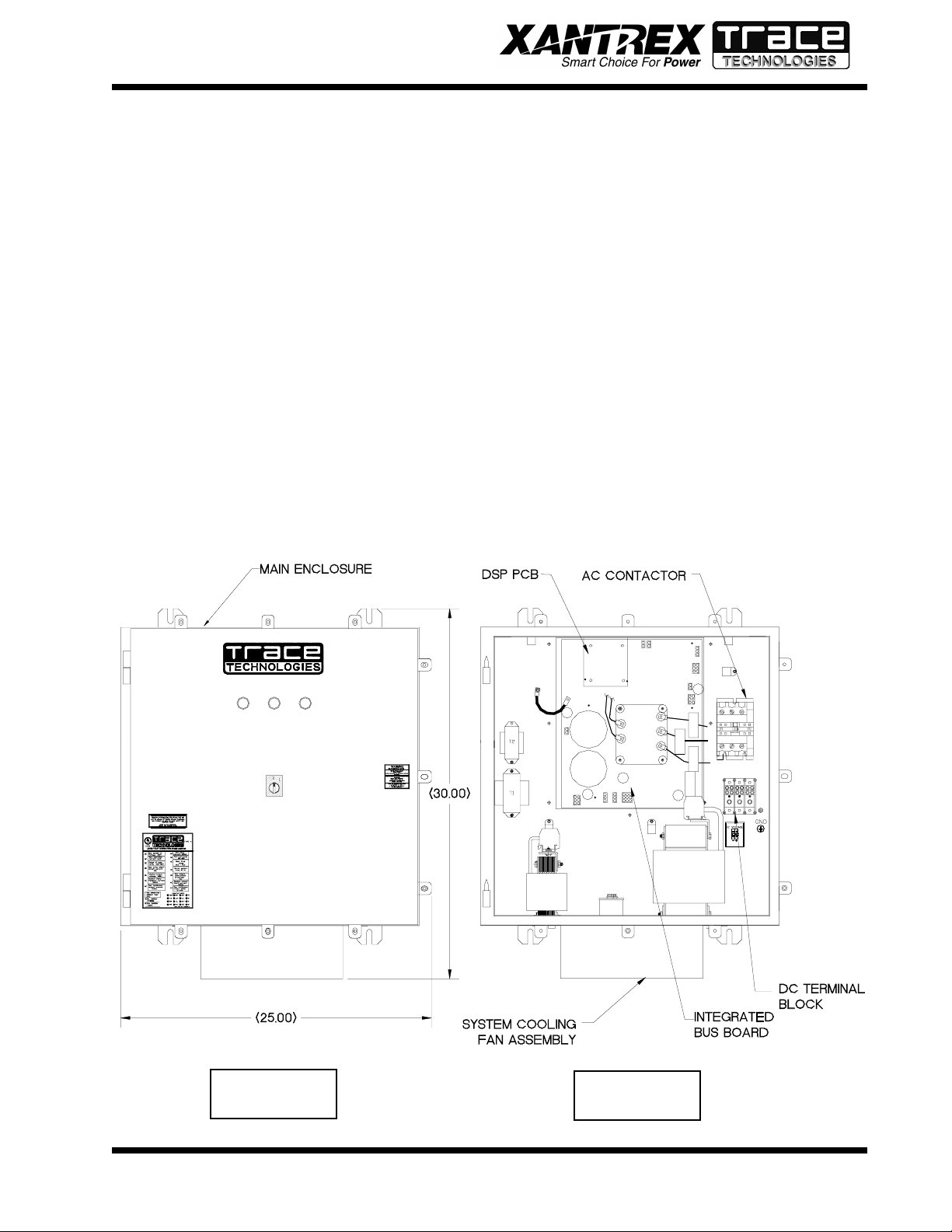
The major components of the PV-20208 are identified in Drawing No. 151121.
Main Enclosure
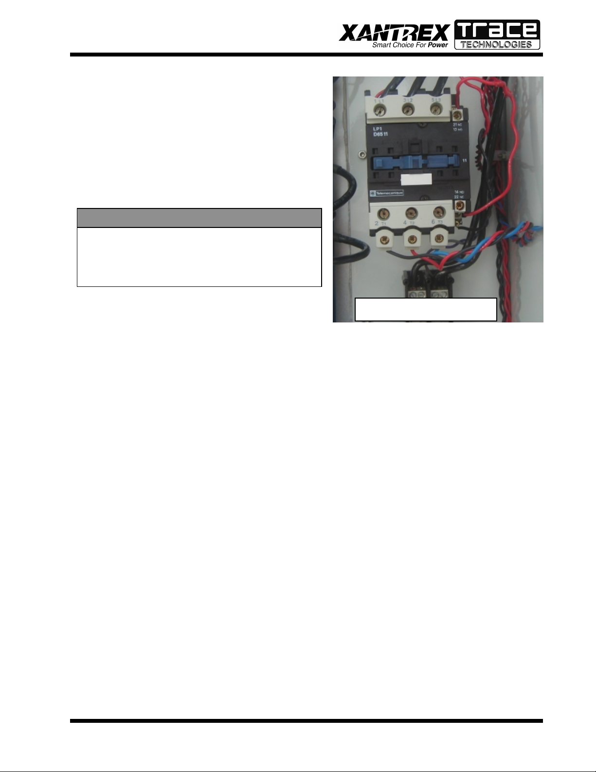
The enclosure (shown in Figure 1-1) is NEMA-4 rated. The PV-20208 enclosure contains the Integrated Bus Board, output line filter (insuring that the PV-20208 line currents and voltages meet IEEE519 harmonic distortion requirements), control power transformers, and A/C contactor (PV-20208 A/
C output to the grid). Also found within the enclosure are the system protection devices (control power
circuit fuses). The front door of the enclosure contains the operator interface panel (three LED’s or
LCD and an on/off switch).
1-1
Figure 1-1
Figure 1-2
PV-20208 Photovoltaic Inverter
Operation and Maintenance Manual
Copyright 2000, Xantrex Technologies Inc./Trace Technologies Corp.
DOCUMENT: 151119
Page 4

SECTION 1
PRODUCT DESCRIPTION
CAUTION
The fuses within the PV-20208 are intended for protecting the PV-20208 control circuitry only. They are not intended to provide protection for the PV array or external
cabling.
Integrated Bus Board
The PV-20208 design makes use of a fully integrated bus board as shown in Figure 1-2. The bus board
assembly is mounted to an aluminum extrusion heat sink, which mounts through an opening in the
back of the enclosure. The power electronics is comprised of a six pack of IGBT devices, mounted to
the heat sink. The bus board is mounted on top of the IGBT six pack device, and is supported through
a series of standoffs attached to the heat sink.
The bus board contains all of the necessary control functions to drive the (attached) switching transistors. The bus board contains the following functional circuits: D/C control power supplies (+5V, +/15V and four isolated +15V sources for the IGBT’s), A/C and D/C high voltage measurement, A/C and
ground current measurements, contactor and indicator controls, discrete input sensing (on/off switch),
and closed loop PWM modulators. The bus board contains a micro-controller chip to perform the lowlevel control functions associated with the collection of measurement and driving the pulse width
modulators.
A plug in DSP module controls the bus board. The DSP module is designed to the industry standard,
PC-104 specification, and is used to perform the majority of the calculations needed to control the bus
board. The most significant tasks are: control of PV-20208 electromechanical components and power
electronics converters, signal conditioning (digital filtering and transformations), and communication
with the operator interface panel and system sensors.
The PV array ties directly to the DC bus. The inverter controller manages the transfer of power between
the DC bus and the utility grid.
INTERCONNECTION STANDARDS COMPLIANCE
The PV-20208 has been tested and certified by Underwriters Laboratories to be in compliance with
UL1741 Static Inverters And Charge Controllers For Use In Photovoltaic Power Systems, as well
as IEEE-P929 Recommended Practice For Utility Interface Of Photovoltaic (PV) Systems.
IEEE-P929 provides guidance regarding equipment and functions necessary to ensure compatible operation of photovoltaic systems which are connected in parallel with the electric utility. UL1741 is the
test procedure performed by Underwriters Laboratory on the PV-20208 to verify it meets the recommendations of IEEE-P929. Refer to both documents for details of these recommendations and test
procedures.
1-2
PV-20208 Photovoltaic Inverter
Operation and Maintenance Manual
Copyright 2000, Xantrex Technologies Inc./Trace Technologies Corp.
DOCUMENT: 151119
Page 5
SECTION 1
PRODUCT DESCRIPTION
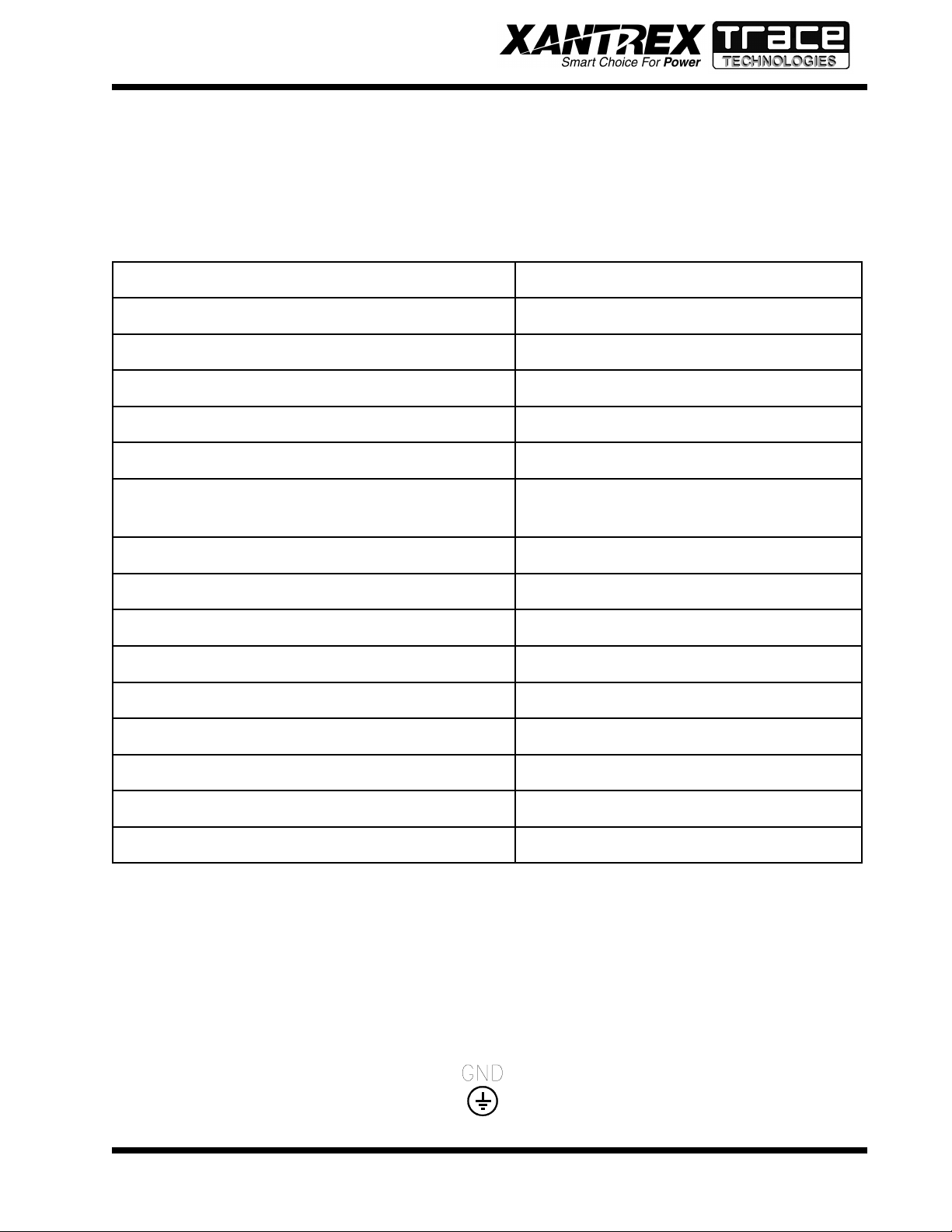
SPECIFICATIONS
The PV-20208 has been designed for photovoltaic power systems, which operate within the following
specifications. Application of the PV-20208 in a manner inconsistent with these specifications may
cause damage to the PV-20208 and other system components, and is a violation of the terms of the
warranty.
egatloVeniLCAlanimoN%01±,CAV802
tnerruCeniLCAmumixaM )egatlovenilwolta(SMRA86.16
ycneuqerFeniLlanimoNzH5.0±,zH06
daoLCAsuounitnoCCAv802@WK0.02
egnaRegatloVVPCDV006-033
tnerruCmumixaMVPCDA8.36
noitarugifnoCVP
dnuorglartuen
ralop-ibro,dednuorgevitagenraloponoM
erutarepmeTgnitarepO*C°05ot02-
erutarepmeTegarotSC°05ot04-
gnitaRerutarepmeTtneibmAmumixaMC°05
ytidimuHevitaleRgnisnednoc-noN,%59oT
noitavelEteef006,6evobadetareD
)sehcnini(snoisnemiD41X52X03
thgieW.sbl571.xorppA
epyTerusolcnE4AMEN
eliFgnitsiLLU653991E-eliF
*If ambient temperature is between -20 to 0° C, the unit must be powered up in standby for at least
one hour prior to going on-line.
EQUIPMENT SYMBOL
Chassis ground – Customer supplied system ground connection point. This symbol may be found near
a stud within the main enclosure. It is provided as a location to bond the electrical system equipment
ground.
1-3
PV-20208 Photovoltaic Inverter
Operation and Maintenance Manual
Copyright 2000, Xantrex Technologies Inc./Trace Technologies Corp.
DOCUMENT: 151119
Page 6
SECTION 2
SAFETY
SAFETY FEATURES
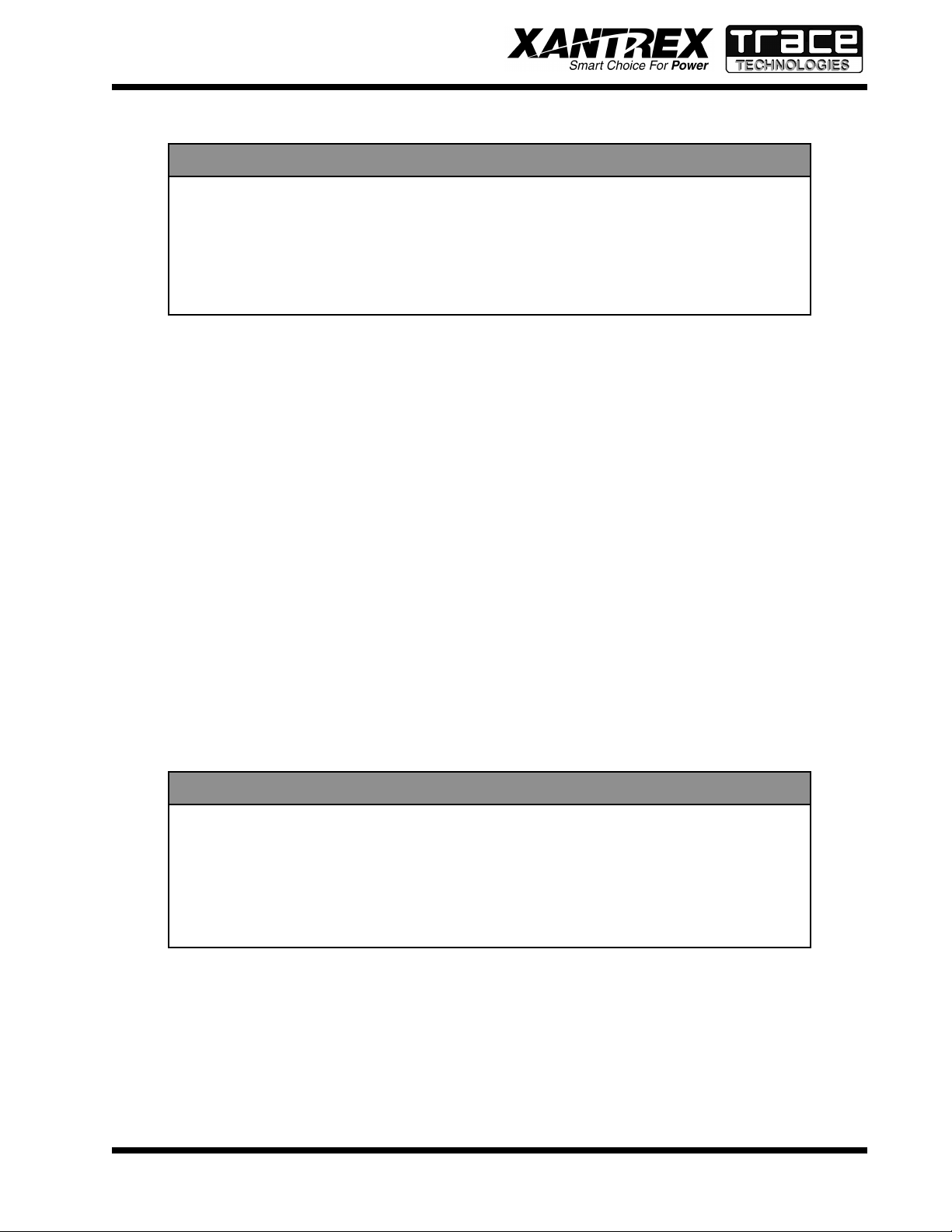
WARNING
The PV-20208 enclosure contains exposed high voltage conductors. The enclosure
door should remain closed, except during maintenance or testing. These servicing
instructions are for use by qualified personnel only. To reduce the risk of electric
shock, do not perform any servicing other than that specified in the operating
instructions unless you are qualified to do so. Do not open the cabinet door if
extreme moisture is present (rain or heavy dew).
Front Panel Indicators
The PV-20208 incorporates three colored LED indicators, used to show the current operating state of
the inverter. The indicators have the following meanings:
• Red: Fault Mode - The inverter has sensed an abnormal condition. To reset the unit (clearing the
fault condition), cycle the on/off switch (see below).
• Amber: Sleep Mode – The inverter is waiting for sufficient PV voltage to start the inverter.
• Green: Operator Mode - The inverter is active and generating A/C current.
On/Off Switch
The PV-20208 incorporates a maintained position on/off switch located on the front door of the enclosure. Under normal conditions, the on/off switch in the on position. Turning the switch to the off
position will initiate a controlled shutdown of the PV-20208 and open the main contactor within the
unit. The PV-20208 is prevented from being restarted until the on/off switch is turned back to the on
position. Cycling the on/off switch will reset the PV-20208 and attempt to clear any system fault.
Main Enclosure Door
The front door of the PV-20208 main enclosure is pad lockable. It is recommended that the PV-20208
enclosure door be padlocked during normal operation.
WARNING
The PV-20208 does not incorporate a door interlock switch. Please make sure the
unit is powered down, and isolated from the utility grid and PV panels, prior to
opening the enclosure door. (Allow 5 minutes for any stored potentials to be discharged, prior to opening the unit). The front door of the PV-20208 main enclosure
is pad lockable. It is recommended that the PV-20208 enclosure door be padlocked
during normal operation.
Fault Reporting
Any fault conditions are reported to the operator interface. If the PV-20208 is equipped with LED’s,
the red LED will light and the green LED will flash the corresponding number of the fault. If the PV20208 is equipped with the LCD option, the LCD will display a text description of the fault. Refer to
Section 5, Troubleshooting, for detailed descriptions of system fault conditions.
PV Ground Fault Detection
The PV-20208 is equipped with ground fault detection circuitry and control. The single point of PV
2-1
PV-20208 Photovoltaic Inverter
Operation and Maintenance Manual
Copyright 2000, Xantrex Technologies Inc./Trace Technologies Corp.
DOCUMENT: 151119
Page 7
SECTION 2
SAFETY
system ground must be routed through CT1 on the main control board (see section 3, installation and section 7, system schematic for further detail). Upon detection of 1.5 amps of ground
fault current, the PV-20208 executes an orderly shutdown, and annunciates a ground fault at the
operator interface. The PV-20208 will remain faulted until the ground fault is remedied and
cleared at the operator interface (see section 5, troubleshooting).
ISOLATION PROCEDURE
The following procedure should be followed to de-energize the PV-20208 for maintenance:
WARNING
The terminals of the PV input may be energized if the arrays are energized. In
addition, allow 5 minutes for all capacitors within the enclosure to discharge after
disconnecting the PV-20208 from AC and DC sources.
1. Turn the on/off switch to the off position.
2. Open the PV array disconnect switch (if present).
3. Open the AC interface disconnect (if present).
4. Open the isolation transformer circuit breaker.
5. Install lockout devices on the isolation transformer circuit breaker and PV disconnect switch (if
present).
ANTI ISLAND PROTECTION
A digital phase-shift-loop (PSL) circuit is implemented in the DSP inverter controller to prevent
“Islanding” of the PV-20208.
The DSP continuously makes minor adjustments to the power factor phase angle above and below
unity. In the event of a utility outage, these adjustments destabilize the feedback between the inverter
and the remaining load, resulting in an over/under frequency or voltage condition. The PV-20208
then performs an orderly shutdown. The fault condition will remain until the utility voltage and
frequency have returned to normal for 5 minutes.
This method has been extensively tested and proven to exceed the requirements of UL 1741.
2-2
PV-20208 Photovoltaic Inverter
Operation and Maintenance Manual
Copyright 2000, Xantrex Technologies Inc./Trace Technologies Corp.
DOCUMENT: 151119
Page 8
SECTION 3
INSTALLATION AND INITIAL TURN-ON
ISOLATION TRANSFORMER REQUIREMENTS
The PV-20208 is required to have an isolation transformer wired between the inverter AC output and
the utility interconnection. Any standard dry-type isolation transformer is compatible with the PV20208 as long as the inverter side is rated for a minimum of 20KVA continuous duty.
WARNING
Check with the local utility of jurisdiction when selecting the winding configuration of the isolation transformer. Individual utilities may have unique requirements related to isolation transformer wiring. Some winding configurations may
keep the PV-20208 from detecting a loss of phase condition on the utility system
which may allow potentially lethal voltage to be present on the open phase wirings.
Inverter Side Isolation Transformer Requirements
The inverter side transformer windings may be configured either delta or WYE, and must be rated for
208 VAC. Trace Technologies recommends using a delta wound transformer to avoid installation mistakes. If a WYE wound transformer is used to interface with the PV-20208, and the PV array is
grounded, the neutral (X0) must be left floating. If the neutral is tied to ground, the inverter will not
function properly , and may be damaged.
Utility Side Isolation Transformer Requirements
The utility side isolation transformer windings may be configured either delta or WYE, and must be
rated for the utility voltage at the point of utility inter-connection. Check with the utility of jurisdiction
when selecting an isolation transformer configuration. If a WYE wound transformer is used to interface
with the utility , it is not necessary to connect the neutral (X0) to ground. The PV-20208 is a balanced,
three phase, current sourcing inverter, and only operates with the presence of a stable utility voltage.
Single phase grounded loads which may be present between the transformer and utility, will maintain
their existing ground reference at the utility distribution transformer . Grounding the neutral of a WYE
wound transformer may create an “open delta” condition, depending on the utility configuration. This
condition may keep the PV-20208 from detecting a loss of phase condition on the utility system,
which may allow potentially lethal voltage to be present on the open phase wiring.
Contact your Xantrex/Trace Technologies distributor if you have any questions regarding isolation
transformer requirements.
TORQUE AND WIRE GAUGE SPECIFICATIONS
The following torque specifications are to be used on all electrical interfaces made during installation
of the PV-20208.
T orque Table
3-1
eziStloBrokcolBlanimreTgnitteSeuqroT
1-6MmN9.5/.sblni25
23126tumwahS/zarreFmN6.31-3.2/sblni021-02
PV-20208 Photovoltaic Inverter
Operation and Maintenance Manual
Copyright 2000, Xantrex Technologies Inc./Trace Technologies Corp.
DOCUMENT: 151119
Page 9
SECTION 3
INSTALLATION AND INITIAL TURN-ON
The following table shows acceptable wire gauges to be connected to the PV-20208 AC and DC
inputs.
Wire Gauge Table
noitanimreTGWAegnaReriW
)CA(rotcatnoC01#-3#
)CD(kcolBnoitubirtsiD41#-0/2
INSTALLATION INSTRUCTIONS
CAUTION
All wiring methods shall be in accordance with the National Electrical Code ANSI/
NFPA 70. All power conductors interfacing to the PV-20208 should be sized in
accordance with the National Electric Code ANSI/NFP A 70 and local codes. Large
gauge wire must have a minimum bend radius dependent upon the wire gauge
(refer to the National Electric Code, Article 373-6B). Take care to keep the wire
bundles away from any sharp edges which may damage wire insulation over time.
Trace Technologies recommends using No. 6 AWG, 105 degrees C, minimum,
copper wire for all connections with the PV-20208.
Ventilation Considerations
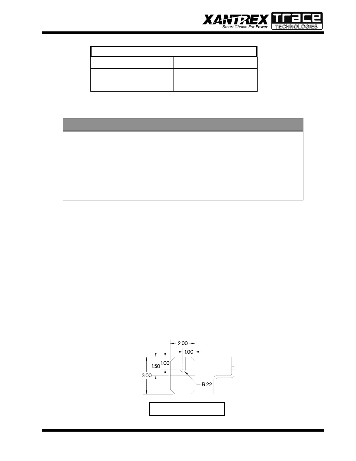
1. Maintain a minimum 6” clearance above and below the PV-20208 for proper cooling fan operation.
2. Maintain a minimum 1” clearance to the left and right of the PV-20208.
Installation
1. The unit must be mounted at least 3’ off the ground, and 12” above any horizontal surface.
2. Screw two 3/8” x 3-1/2” long lag bolts into existing studs in the wall (16-inch mounting center) at
lower mounting level on PV-20208. Lag bolts should be horizontally level with each other. Leave
a minimum of 1” of bolt protruding from the wall.
3. Place the PV-20208 bottom mounting ears, shown in Figure 3-1 and Figure 3-2 onto installed lag
bolts. (See following page.)
4. Hold the unit against wall and install upper lag bolts (3/8” x 3-1/2”). Tighten bolts firmly.
5. Tighten lower lag bolts while unit is held in place.
6. Install two 1-1/2” liquid tight connectors (included with the PV-20208) where shown in
Figure 3-3. (See following page.)
3-2
Figure 3-1
PV-20208 Photovoltaic Inverter
Operation and Maintenance Manual
Copyright 2000, Xantrex Technologies Inc./Trace Technologies Corp.
DOCUMENT: 151119
Page 10
SECTION 3
CT1
INSTALLATION AND INITIAL TURN-ON
Figure 3-2
Figure 3-3
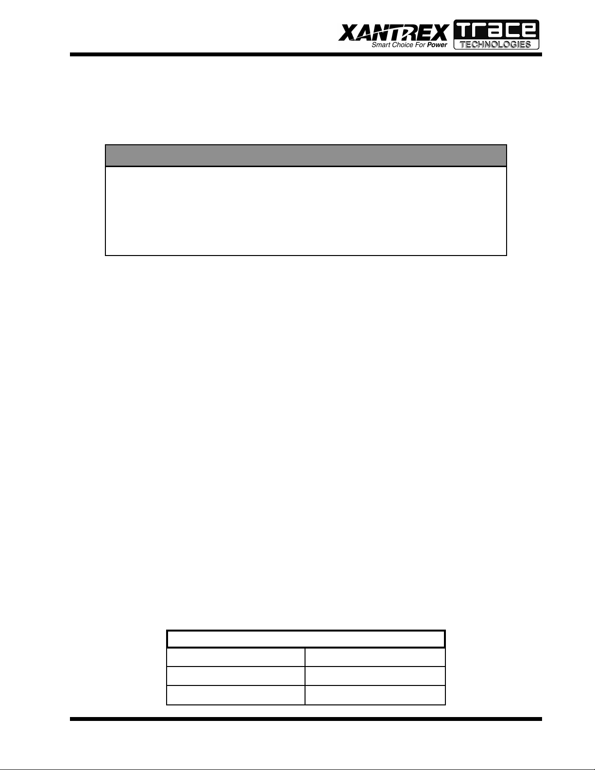
Array Grounding and Ground Fault Detection
If grounding the PV array is required for monopolar or
bipolar arrays, jumper TB1-2 to a (PV-) cabinet ground
stud. If ground fault detection is required, route this
jumper through CT1 located on the lower right hand
corner of the control board (see the system schematic
for further detail). This must be the only point of PV
grounding for the PV-20208 and the ground fault
detection system to function properly .
LIQUID TIGHT CONNECTORS
CAUTION
The input and output circuits are isolated from
the enclosure, and that system grounding, if required by sections 690-41 and 690-42 of the National Electric Code, ANSI/NFPA 70, is the
responsibiliy of the installer.
3-3
PV-20208 Photovoltaic Inverter
Operation and Maintenance Manual
Copyright 2000, Xantrex Technologies Inc./Trace Technologies Corp.
CONTROL BOARD & CT1
DOCUMENT: 151119
Page 11
SECTION 3
INSTALLATION AND INITIAL TURN-ON
Phase-Sequencing
The PV-20208 is equipped with an automatic phasedetection control algorithm. This allows the utility
interface conductors to be connected in any sequence
convenient at the time of installation. Upon system
initialization at power-up, the PV-20208 determines
the phase sequence of the utility connection and
configures the modulator drivers accordingly .
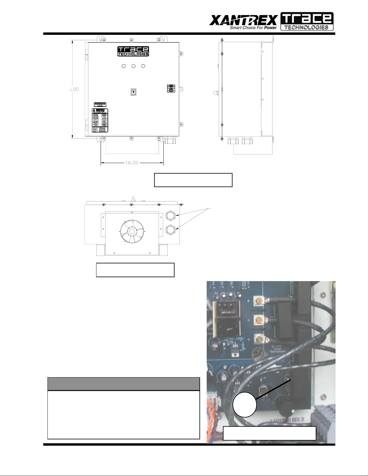
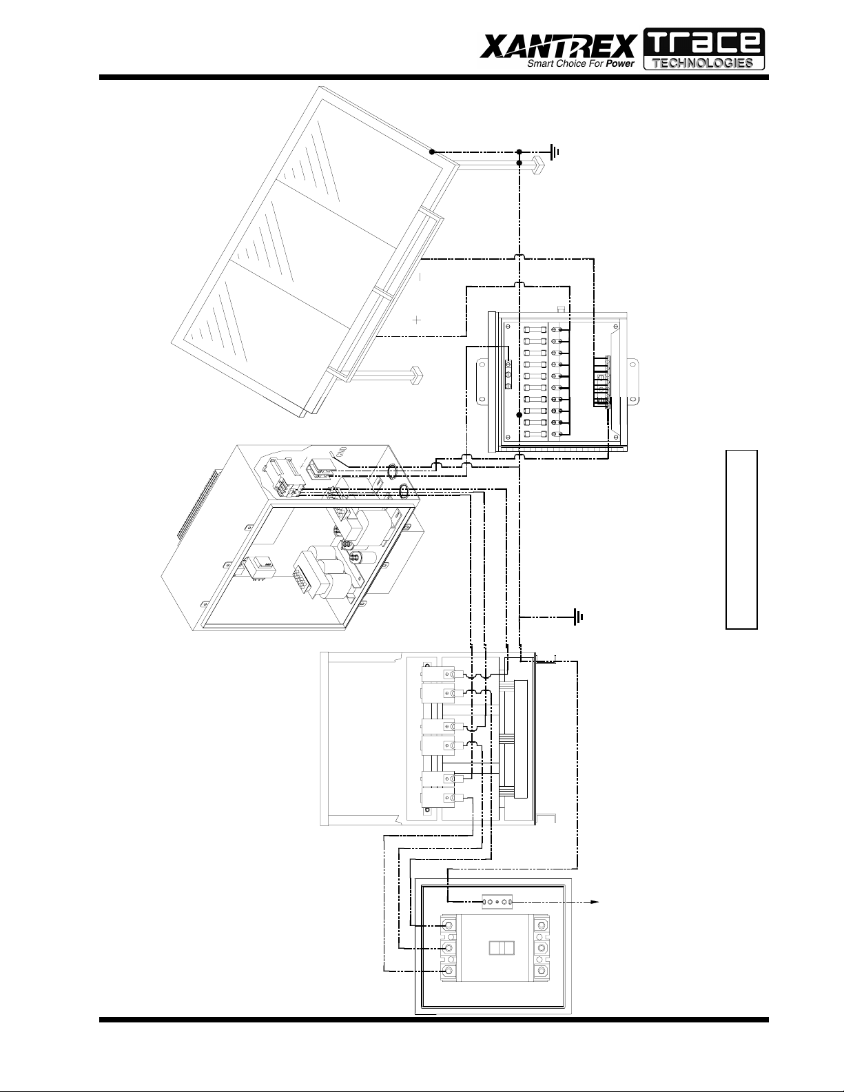
INTERCONNECTION WIRING
CAUTION
To reduce the risk of fire, connect only to a circuit provided with 90 amperes maximum branch
circuit overcurrent protection in accordance with
the National Electrical Code, ANSI/NFPA 70.
The following wires for connecting the PV-20208 to external devices are not provided by Xantrex/Trace Tech-
MAIN CONTACTOR
nologies: (See wiring diagram on the following page.)
• 3-Phase 208 VAC inverter output (main contactor, see picture) to terminals of the 208 VAC delta
side of isolation transformer. If the inverter side of the isolation transformer is configured
WYE and the PV array is grounded, the neutral must be left floating. Ground loops will
exist when the inverter starts switching, which will cause the inverter to shut down due to
phase over-currents and may result in damage to the PV-20208. Also, insure that this
neutral is not bonded to the isolation transformer frame.
• System ground to the isolation transformer chassis ground.
• Isolation transformer grid side terminals to line circuit breaker (or the AC disconnect switch if
present).
• PV frame ground to PV-20208 enclosure chassis ground stud.
• PV-20208 enclosure chassis ground stud to the electrical distribution system ground.
• PV+ to the inverter enclosure terminal block TB1-1.
• PV- to the inverter enclosure terminal block TB1-2.
Install all wires listed above. Refer to the system schematics in Section 7 for more detailed terminal
locations.
3-4
PV-20208 Photovoltaic Inverter
Operation and Maintenance Manual
Copyright 2000, Xantrex Technologies Inc./Trace Technologies Corp.
DOCUMENT: 151119
Page 12
SECTION 3
INSTALLATION AND INITIAL TURN-ON
Frame
PV Array
Ground
Inverter
PV-20208
X1 H1 X2 H2 X3 H3
PV+
X0
Isolation
Transformer
PV-
(Optional)
Trace Combiner Box
Wiring Diagram
3-5
C
B
A
PV-20208 Photovoltaic Inverter
Operation and Maintenance Manual
Copyright 2000, Xantrex Technologies Inc./Trace Technologies Corp.
To Single Point Electrical
Distribution System Ground
Breaker
Line Circuit
DOCUMENT: 151119
Page 13

SECTION 3
INSTALLATION AND INITIAL TURN-ON
INITIAL TURN ON PROCEDURE
The following procedures are intended to verify correct installation and proper operation of the PV-
20208. These steps are to be followed sequentially. Do not continue if any of the steps or results are
unclear. Refer to Section 4 for a detailed description of system operation. Refer to Section 5 for fault
condition descriptions and troubleshooting. Refer to Section 7 for detailed system schematics.
Visual Inspection, Isolation Transformer
• Verify the isolation transformer circuit breaker is open.
• Remove the isolation transformer access panel.
• If the inverter side of the isolation transformer is configured WYE, the neutral must be left floating.
The transformer neutral must not be connected to the utility side neutral, the transformer chassis, or
ground.
• Verify the inverter 208 VAC conductors are connected to the isolation transformer.
• Verify the utility conductors are properly connected to the isolation transformer.
Visual Inspection, PV-20208
• Insure AC and DC disconnect are opened (if present).
• Insure PV array string disconnect switches are opened (if present).
• Open the door of the enclosure, and inspect.
• Verify all wire connections are tight.
• Inspect the cables between the terminal blocks and the matrix driver board. All wire harnesses
should be snap-locked into their respective PCB headers.
Visual Inspection, PV Array Wiring
• Verify the PV+, PV-, PV neutral (if array is bipolar), and PV
safety ground are isolated from each other. The PV safety
ground should be bonded to the enclosure ground stud. Refer to system schematic in Section 7.
• Verify all PV fuses are installed (if present).
• Verify PV string diodes are wired properly (if present).
• V erify proper PV voltage polarity at the PV string disconnect/
combiner boxes.
Initial Power
• Close the isolation transformer circuit breaker.
• Verify 208 VAC voltage across the AC disconnect.
• Close the AC disconnect (if present).
• With the DC disconnect switch opened (if present), close one
of the PV array string disconnect devices.
• Carefully measure VDC at the PV disconnect switch. The
value should be the same as at the PV array string disconnect
device. It should also be positive.
• Close the PV disconnect switch (if present).
• Carefully measure VDC across TB1-1 and TB1-2 (PV +/-)
terminal block. The value should be the same as at the PV
DC TERMINAL
3-6
PV-20208 Photovoltaic Inverter
Operation and Maintenance Manual
Copyright 2000, Xantrex Technologies Inc./Trace Technologies Corp.
DOCUMENT: 151119
Page 14

SECTION 3
INSTALLATION AND INITIAL TURN-ON
array string disconnect device. It should also be positive.
• Carefully measure VDC across the matrix + and – busses. The value should be the same as at the
PV array string disconnect switch. It should also be positive.
• Open the PV disconnect switch. The matrix capacitor bank voltage should slowly degrade to near
zero over a 5-minute period.
• Open all PV string disconnect switches.
System Verification
• Ensure the on/off switch is enabled.
• Upon applying 208 VAC power to the PV-20208, observe the three LED indicator lights on the
front door. The LED’s should be switching on and off in a sequenced pattern. The LED’s may be
difficult to see depending on external light conditions. After approximately 15 seconds, the panel
should finish initialization
• Remedy any faults reported. If the fault indicator does not change, the fault condition is still present
(see Section 5). Cycling the on/off switch will reset the PV-20208 and attempt to clear any system
faults. Once all faults are cleared, the amber indicator light will come on indicating the PV-20208
is in standby .
• Close all PV array string disconnect switches (if present).
• Close the main PV disconnect switch (if present).
• If the PV voltage is above the PV Start Voltage setpoint, and the PV Start Time is exceeded, the PV-
20208 should transition to “Power Tracking” (see Section 4, Operation).
• Depending upon solar conditions, the PV-20208 may not operate at full power. If the PV array is
not experiencing full sun, the PV maximum power tracker will regulate the PV voltage to maintain
maximum PV power output. (See section 4 for further description of the peak power tracker).
• The PV-20208 is now fully operational.
Fine Tuning
• All PV-20208 operating parameters have been set at the factory , based upon prior experience with
various PV arrays. Parameters may be modified using an optional graphical user interface. Contact
your Xantrex/Trace Technologies distributor for further information.
• It is recommended that the PV-20208 be watched during W ake-Up and Sleep T est. If the PV-20208
cycles between operating and sleeping at either of these times, the operating setpoints may not be
set properly . (Refer to Section 4 for a detailed description of PV-20208 operating states). The PV20208 should not cycle if the setpoints are set properly.
3-7
PV-20208 Photovoltaic Inverter
Operation and Maintenance Manual
Copyright 2000, Xantrex Technologies Inc./Trace Technologies Corp.
DOCUMENT: 151119
Page 15

SECTION 4
OPERATION
DESCRIPTION OF SYSTEM OPERATION
Overview
The PV-20208 is a fully automated grid-tied photovoltaic inverter. Manual interaction or control of the
inverter is necessary only in the event of a system fault. The following conditions govern PV-20208
operation:
• Stable utility voltage and frequency must be present for all states of operation.
• Fault states are automatic from any state of operation. A fault will cause the PV-20208 to immedi-
ately stop processing all power. The fault condition will be reported to the operator interface.
• The on/off switch, located on the front door of the PV-20208, must be switched to the on position
for all operating states.
• Cycling the on/off switch attempts to clear any system faults and return the PV-20208 to normal
operation.
Operating States
Control software governs the operation of the PV-20208. There are five main operating states. The
following descriptions depict the LED interface. Inverters configured with LCD displays will indicate
operating states on the display.
• Standby: The amber LED is illuminated. The PCU monitors the status of the PV array and utility
grid, waiting until the PV array voltage is sufficient to export power to the utility.
• Wake-Up: The amber LED is illuminated. Once the PV voltage is sufficient to export power to the
utility grid, the PV-20208 will wait 5 minutes before starting to insure the voltage is not transient in
nature. This keeps the system from cycling during unstable irradiance conditions.
• Power Tracking: The green LED will illuminate while the PV-20208 delivers power to the utility.
This is the standard operating state of the PV-20208. The PV-20208 maximum power tracker will
optimize power output from the PV array. If available PV power is above the maximum power
rating of the PV-20208, the inverter will current limit, which will cause the PV voltage to rise
above the array peak power voltage. The minimum operating voltage of the PV-20208 is 330 VDC.
The power tracker will not track voltage below this point, regardless of the actual peak power
voltage of the PV array.
• Sleep Test: The control system will begin a 5 minute sleep test. This normally indicates the PV
irradiance is declining as the sun sets. If the output power remains below 200 watts during the 5
minute sleep test, the system will transition to standby. The time delay allows the inverter to ride
through any temporary irradiance reductions.
• Fault: The PV-20208 has encountered a fault condition. When this happens, regardless of the PV-
20208 state-of-operation, the PV-20208 will stop processing all power and execute an orderly system shutdown. The red LED will illuminate while the yellow and green LED’s flash the fault code
(See section 5, Troubleshooting).
OPERATOR INTERFACE (LED and LCD)
NOTE
On early versions of the PV-20208, a push-pull Emergency Stop switch was used
instead of the on/off switch. It functioned in the same manner described for the on/
off switch.
4-1
Copyright 2000, Xantrex Technologies/Trace Technologies Corp.
PV-20208 Photovoltaic Inverter
Operation and Maintenance Manual
DOCUMENT: 151119
Page 16

SECTION 4
OPERATION
The standard operator interface on the PV-20208 consists of 3 system status indicator LED’s and an
on/off switch. The LED’s indicate the following states of operation:
• Red LED: Indicates the system is faulted or the on/off switch is switched to the off position. The
inverter will not function while this LED is illuminated. Cycling the on/off switch will attempt to
clear the fault condition and allow the inverter to resume normal operation.
• Amber LED: Indicates the inverter is in standby, waiting for sufficient DC voltage to begin peak
power tracking. This LED will turn off once the PV-20208 begins producing power. In the event of
a fault condition, the amber LED will flash, indicating the beginning of the fault code sequence
(See section 5, Troubleshooting).
• Green LED: Indicates the inverter is on-line and outputting power. In the event of a fault, the green
LED will flash a sequence indicating the fault code (See section 5, Troubleshooting).
The on/off switch is used to enable or disable system operation. The on/off switch is also used to reset
the inverter and clear any system faults.
The PV-20208 may be equipped with an optional Liquid Crystal Display instead of the LED indicators.
The display consists of 4 text lines containing the following information:
• Line 1: System Goal State - This is the target state of the inverter.
• Line 2: System Status - The current operating state of the inverter.
• Line 3: Inverter Output Power or Fault Description - During normal operation, this line will
report the inverter real time output power. If the PV-20208 is faulted, this line will report a description of the fault condition.
• Line 4: PV Voltage - The DC voltage measured at the PV-20208 DC input terminals.
The following is a typical display of the LCD during the five operating states and an on/off switch.
Status: Power Track
Shutdown
Standby
Status: Power Track
Wake Up Test
Status: Power Track
Sleep Test
Sleep Test
Status: Power Track
Faulted
Fault Description
4-2
Wake Up
Status: Power Track
Power Tracking
Line kVA:
PV Volts:
Power Tracking
PV-20208 Photovoltaic Inverter
Operation and Maintenance Manual
Copyright 2000, Xantrex Technologies/Trace Technologies Corp.
Fault
Status: Power Track
Emergency Stop
Emergency Stop
DOCUMENT: 151119
Page 17

SECTION 4
OPERATION
EXAMPLE OF NORMAL SYSTEM OPERATION
Upon initial application of AC voltage, the LED’s located on the front door will sequentially flash for
approximately 15 seconds. Once the system has finished initializing, the PV-20208 will remain in
standby until adequate PV voltage is available (amber LED is lit). 5 minutes after the PV start voltage
has been reached, the PV-20208 will synchronize to the utility grid and begin peak power tracking the
PV array. The time delay protects the inverter from excessive on/off cycling.
The PV-20208 will continue to process power until the AC output power approaches the operating
losses of the inverter for a period of 5 minutes. The time delay protects the inverter from excessive on/
off cycling.
SYSTEM OPERATING PARAMETERS
The PV-20208 contains a number of system operating parameters which may be field adjusted using an
optional graphical user interface program available first quarter, 2001 (contact Xantrex/Trace Technologies for further information). All operating parameters have been set at the factory during system
test based upon prior experience with various PV arrays, or to be in compliance with UL1741. In
general, the factory default settings allow for stable and efficient operation of the PV-20208 connected
with any PV array configured for a 330-500 VDC peak power voltage point.
Below is a list of the PV-20208 operating parameters, showing valid ranges and the factory default
settings. Some field adjustable parameters are password protected and may only be changed by trained
service technicians. In particular are parameters relating to utility protection setpoints. These have been
set in the factory to the limits mandated by UL1741. Any changes to these setpoints should be agreed
upon by the local utility and the equipment owner. The ability to adjust the voltage and frequency
setpoints across the actual utility voltage and frequency has been provided as a simulation tool to verify
the PV-20208 accurately detects and responds to a utility excursion. This test should only be performed
by a trained service technician. It is possible to adjust the setpoints in a manner that will prevent the
PV-20208 from functioning.
retemaraPnoitpircseD
resU
elbatteS
noituloseR
egnaR
yrotcaF
tluafeD
gnitteS
drowssaP
detcetorP
tratS_V_VPegatloVpUekaWVP006-233V1.0083
sttaW_potS_VP
rewoP
tuptuOnwoDtuhSVP
0001-001W1.0002
tuptuOdednammoC
reP_I_xaM_TPP
fOtnecrePAsArewoP
001-0A1001*
rewoPdetaR
4-3
feR_V_TPP
roFegatloVVPgnitratS
rekcarTrewoPkaeP
006-233V1.0053
-continued-
PV-20208 Photovoltaic Inverter
Operation and Maintenance Manual
Copyright 2000, Xantrex Technologies/Trace Technologies Corp.
DOCUMENT: 151119
Page 18

SECTION 4
OPERATION
retemaraPnoitpircseD
resU
elbatteS
noituloseR
egnaR
yrotcaF
tluafeD
gnitteS
drowssaP
detcetorP
rekcarTrewoPkaeP
petS_V_TPP
petSnoitabretreP
0.01-0.0V1.05.1
egatloV
xaM_I_dnuorG
elbawollAmumixaM
tnerruCtluaFdnuorG
0.01-0.1A1.00.3
rebmuNlaireSrebmuNlaireSretrevnI9999-0000A/NteSyrotcaF*
xaM_qerF
niM_qerF
elbawollAmumixaM
ycneuqerFytilitU
elbawollAmuminiM
ycneuqerFytilitU
0.36-0.75zH1.05.06*
0.36-0.75zH1.05.95*
elbawollAmumixaM
yaleD_xaM_qerF
AoTesnopseRemiT
ycneuqerFhgiHytilitU
06-0elcyC13*
noisrucxE
elbawollAmumixaM
yaleD_niM_qerF
AoTesnopseRemiT
ycneuqerFwoLytilitU
06-0elcyC13*
noisrucxE
xaM_CAV
niM_CAV
egatloVytilitU
egatloVytilitU
elbawollAmumixaM
elbawollAmuminiM
6.942-4.661V1.05.022*
6.942-4.661V1.05.591*
elbawollAmumixaM
yaleD_xaM_CAV
AoTesnopseRemiT
egatloVhgiHytilitU
06-0elcyC15*
noisrucxE
elbawollAmumixaM
yaleD_niM_CAV
AoTesnopseRemiT
egatloVwoLytilitU
06-0elcyC15*
noisrucxE
4-4
PV-20208 Photovoltaic Inverter
Operation and Maintenance Manual
Copyright 2000, Xantrex Technologies/Trace Technologies Corp.
DOCUMENT: 151119
Page 19

SECTION 5
TROUBLESHOOTING
GENERAL
In the event of a fault, the PV-20208 will annunciate the condition at the operator interface. The PV20208 will execute an orderly shutdown and remain faulted until the fault is cleared (manually or automatically).
In general, the operator should respond to any PV-20208 fault as follows:
1. The source of the fault should be sought by referring to the following chart.
2. Rectify the fault condition and attempt to clear the fault by cycling the on/off switch.
3. If the problem cannot be corrected, contact your Xantrex/Trace Technologies distributor for assistance or service.
FAULT CONDITIONS AND TROUBLESHOOTING
Fault Code Annunciation
The PV-20208 will report faults by LED display blinking the amber and green LED’ s on the front door
of the inverter . If a fault is detected, the red LED will light continuously and the amber and green LED’ s
will blink the sequence of the fault. The amber LED will light once, indicating the beginning of the fault
code sequence (first count). The green LED will blink X number of times, indicating the remainder of
the fault count. For example: If the PV-20208 experiences a ground fault (fault #3), the yellow and
green LED will flash once then the green LED will flash twice again. This sequence will repeat until the
fault condition has been corrected and cleared.
5-1
LED Display
PV-20208 Photovoltaic Inverter
Operation and Maintenance Manual
Copyright 2000, Xantrex T echnologies Inc./Trace Technologies Corp.
LCD Display
DOCUMENT: 151119
Page 20

SECTION 5
TROUBLESHOOTING
LCD Fault Annunciation (Optional Equipment)
The LCD interface reports fault conditions on Line 2 and 3. The fault code number will follow a text
description. The fault description will remain displayed until the fault has been corrected and cleared.
Each fault is described below .
F AUL T DESCRIPTIONS
noitpircseDtluaFsehsalFDELforebmuN)DCL(edoCtluaF
tnerruCrevOMPI12000x0
erutarepmeTrevOMPI21000x0
tnerruCdnuorG30800x0
egatloVrevOVP/CDWS40400x0
ycneuqerFrednUeniLCA50040x0
ycneuqerFrevOeniLCA60080x0
woLegatloVeniLCA70010x0
hgiHegatloVeniLCA80020x0
egatloVrevOsuBCD90200x0
tluaFmetsySlanretnI010100x0
potSycnegremEenoNenoN
FAULT CLEARING
Once the cause of the fault condition has been corrected, the fault can be cleared with the on/off switch.
First turn the switch to the off position and then back to the on position in order to reset the inverter. If
a fault is sustained the inverter will not reset, and will continue to report the fault. Once the fault clears,
the red LED will turn off and the yellow LED will remain lit.
FAULT DESCRIPTIONS AND TROUBLESHOOTING
(1) IPM Over Current Fault (0x0002)
The IPM module has detected a short circuit/over current condition, or low supply voltage.
Possible causes:
• Short circuit in output AC line.
• Low supply voltage to IPM control circuit.
• Shorted isolation transformer.
5-2
Copyright 2000, Xantrex T echnologies Inc./Trace Technologies Corp.
PV-20208 Photovoltaic Inverter
Operation and Maintenance Manual
DOCUMENT: 151119
Page 21

SECTION 5
TROUBLESHOOTING
(2) IPM Over Temp Fault (0x0001)
The IPM module has exceeded its maximum allowable temperature.
Possible causes:
• Clogged inlet filter .
• External cooling fan inoperable.
• Airflow on heat sink impeded due to accumulation of debris.
• Operation above rated ambient temperature for an extended period of time.
• Auxiliary contact block on contactor K1 inoperable. This is only possible if the fan does not operate
when the contactor closes. Carefully check voltage at the K1-N.O. aux. contact to the ground bus
when the contactor is closed. (See schematic in Section 7)
(3) Ground Current Fault (0x0080)
The earth safety ground current has exceeded the maximum-programmed value.
Possible causes:
• The negative wire from the PV array has been passed through CT1. Remove wire and connect to
TB1-2. Run wire from TB1-2, through CT1, and land at one of the chassis ground studs.
• Inspect the PV array for actual ground faults.
• The PV array has been grounded in more than one location. If the PV array is grounded through
CT1, it must not be grounded at any other location.
• CT1 defective: Contact your Xantrex/Trace Technologies distributor for assistance or service.
(4) SW PV/DC Over Voltage Fault (0x0040)
The PV voltage has exceeded the maximum programmed limit. This limit is set to 600 VDC during
system test.
Check the PV input voltage at the PV disconnect switch. If the voltage is below 600 VDC, restart the
PV-20208.
Possible causes:
• The PV array open circuit voltage exceeded 600 VDC.
• There is a problem with the PV voltage sense wiring (see system schematic in Section 7).
(5) AC Line Under Frequency Fault (0x0400)
The AC utility frequency fell below the minimum programmed limit. This limit is set to 59.5 Hz and the
system response time limit is set to 3 cycles to insure the PV-20208 disconnects from the utility within
the time allowed by UL1741.
Possible causes:
• The utility frequency fell below the allowable limit (59.5 Hz by default). V erify the utility frequency
is stable and within allowable operating limits.
• There is a problem with one or more of the AC sense wires (see system schematic in Section 7).
This fault is auto-resetting. The unit will automatically restart after line has stabilized within normal
limits for 5 minutes.
5-3
PV-20208 Photovoltaic Inverter
DOCUMENT: 151119
Operation and Maintenance Manual
Copyright 2000, Xantrex T echnologies Inc./Trace Technologies Corp.
Page 22

SECTION 5
TROUBLESHOOTING
(6) AC Line Over Frequency Fault (0x0800)
The AC frequency exceeded the maximum-programmed limit. This limit is set to 60.5 Hz and the system
response time limit is set to 3 cycles to insure the PV-20208 disconnects from the utility within the time
allowed by UL1741.
Possible causes:
• The utility frequency exceeded the allowable limit (60.5 Hz by default). V erify the utility frequency
is stable and within allowable operating limits.
• There is a problem with one or more of the AC sense wires (see system schematic in Section 7).
This fault is auto-resetting. The unit will automatically restart after line has stabilized within normal
limits for 5 minutes.
(7) AC Line Voltage Low Fault (0x0100)
The utility AC voltage fell below the minimum programmed limit. There are two levels of response to
low line voltage conditions. The first level of response is set to 195.5 VAC with a time delay of 5 cycles.
By default, the second level is set to 156 VAC with a time delay of 1 cycle, and is not field adjustable.
Possible causes:
• The utility voltage fell below the allowable limit (195.5 VAC by default). V erify the utility voltage is
stable and within allowable operating limits.
• There is a problem with one or more of the AC sense wires (see system schematic in Section 7).
This fault is auto-resetting. The unit will automatically restart after line has stabilized within normal
limits for 5 minutes.
(8) AC Line Voltage High Fault (0x0200)
The utility AC voltage exceeded the maximum-programmed limit. There are two levels of response to
high line voltage conditions. The first level of response is set to 220.5 VAC with a time delay of 5 cycles.
By default, the second level is set to 247.5 VAC with a time delay of 1 cycle, and is not field adjustable.
Possible causes:
• The utility voltage exceeded the allowable limit (220.5 VAC by default). V erify the utility voltage is
stable and within allowable operating limits.
• There is a problem with one or more of the AC sense wires (see system schematic in Section 7).
The fault is auto-resetting. The unit will automatically restart after line has stabilized within normal
limits for 5 minutes.
(9) DC Bus Over Voltage Fault - Hardware (0x0020)
The DC bus voltage has exceeded the maximum limit.
This is also the PV input voltage sense point. Check the PV input voltage at the PV disconnect switch.
If the voltage is below 600 VDC, cycle the on/off switch and restart the PV-20208.
5-4
PV-20208 Photovoltaic Inverter
DOCUMENT: 151119
Operation and Maintenance Manual
Copyright 2000, Xantrex T echnologies Inc./Trace Technologies Corp.
Page 23

SECTION 5
TROUBLESHOOTING
Possible causes:
• The PV array open circuit voltage exceeded 600 VDC.
• There is a problem with the PV voltage sense wiring (see system schematic in Section 7).
(10) Internal System Fault
There has been an internal system fault. Contact your Xantrex/Trace Technologies distributor.
Possible cause:
• There is a problem with the integrated bus board or DSP control board.
Emergency Stop Fault
The on/off switch, located on the front door of the enclosure is disabled. The contact block on the back
of the switch must be open for the PV-20208 to report this message.
If the switch is enabled and the red indicator light is still on, isolate the PV-20208 from external power,
then:
• Verify continuity across the switch contact block while the switch is turned to the on position.
• Verify continuity between P7-1 and P7-2 while the switch is enabled.
This message will display on the second line of the LCD display . It does not indicate a system fault if the
on/off switch is turned to the off position.
5-5
PV-20208 Photovoltaic Inverter
Operation and Maintenance Manual
Copyright 2000, Xantrex T echnologies Inc./Trace Technologies Corp.
DOCUMENT: 151119
Page 24

SECTION 6
PREVENTATIVE MAINTENANCE
Xantrex/Trace Technologies recommends that the following preventative maintenance be carried out
on the PV-20208:
Monthly intervals or as required:
Aluminum Extrusion Heatsink
Accumulation of dirt and debris on the aluminum extrusion heatsink and fan shroud will decrease the ability to transfer heat, which can cause the PV-20208 to shutdown on over-temperature alarms. Inspect the aluminum extrusion heatsink and fan shroud for accumulation of dirt.
Clean if debris is present.
Fan Operation
Verify proper operation of the heatsink cooling fan, located within the shroud below the enclosure. The fan operates when the K1 contactor is closed. Remove any debris from the fan and
finger guard.
Six month intervals:
Enclosure Seals
Inspect the enclosure door seal. If damaged, replace with equivalent closed cell foam gasket.
Call your Xantrex/Trace Technologies distributor for factory replacements or specifications.
Electrical Connections
Inspect the condition of all cables interfacing to the PV-20208. Inspect all wire crimps and
connections for damage caused from high temperature. Check for corrosion. Replace any damaged wires. Verify all mechanical connections are sufficiently tightened.
Enclosure
Access the enclosure and remove any accumulated dirt and debris. Vacuum enclosure whenever
dust or dirt is present.
ISOLATION PROCEDURE
The following procedure should be followed to de-energize the PV-20208 for maintenance:
WARNING
The terminals of the PV input may be energized if the arrays are energized. In
addition, allow 5 minutes for all capacitors within the enclosure to discharge after shutting down the PV-20208.
1. Turn the on/off switch to the off position.
2. Open the PV array disconnect switch (if present).
3. Open the AC disconnect (if present).
4. Open the isolation transformer circuit breaker.
5. Install lockout devices on the isolation transformer circuit breaker and PV disconnect switch.
6-1
PV-20208 Photovoltaic Inverter
Operation and Maintenance Manual
Copyright 2000, Xantrex Technologies Inc./Trace Technologies Corp.
DOCUMENT: 151119
Page 25

SECTION 6
PREVENTATIVE MAINTENANCE
TURN-ON PROCEDURE
Refer to Section 3 for a detailed first-time turn on procedure.
1. Remove any lockout devices from the isolation transformer circuit breaker and PV disconnect
switch.
2. Close the isolation transformer circuit breaker.
3. Close the AC disconnect (if present).
4. Close the PV array disconnect switch (if present).
5. Turn the on/off switch to the on position.
After a 15 second initialization period and a 5 minute wake up period, the PV-20208 will automatically
begin power tracking, given the PV voltage is greater than the PV start voltage setpoint.
6-2
PV-20208 Photovoltaic Inverter
Operation and Maintenance Manual
Copyright 2000, Xantrex Technologies Inc./Trace Technologies Corp.
DOCUMENT: 151119
Page 26

SECTION 7
DRAWINGS AND PARTS LIST
150474 Rev F : Schematic, System, Grid Tied PV Inverter, PV-Series
151121 Rev B : Assembly, Main Enclosure, Control Components, 20 KVA, PV-20208
Table of Components
151120 Rev B : Envelope Drawing, Grid Tied Inverter, PV-20208
Underwriters Laboratories Listing Document, April 25, 2000
Underwriters Laboratories Listing Card, September 8, 2000
Accessories:
151258 - Combiner Box, 10 Pole, 600 VDC, Nema 3R
151260 - Combiner Box, 12 Pole, 600 VDC, Nema 3R
151179 - Transformer, 20 KVA, 3 Pole, 60 Hz, 208 Delta/208-120V
151180 - Transformer, 20 KVA, 3 Pole, 60 Hz, 208 Delta/480-277V
PV-20208 Photovoltaic Inverter
7-1 Operation and Maintenance Manual
Copyright 2000, Xantrex Technologies Inc./Trace Technologies Corp.
DOCUMENT: 151119
Page 27

Page 28

Page 29

Trace Technologies PV-20208
Photovoltaic Inverter
Major Parts List
Assembly Description: Main Enclosure, Control Components, PV-20208
Trace Technologies Assembly # 151121
Item # Qty Reference Designator Trace Technologies Part # Description
1 1 1-151139-01 Fab, Enclosure
2 1 1-150691-01 Heatsink, 339.88 X 387.35
3 1 1-151146-01 Fab, Fan Shroud
4 1 T1 1-150438-01 Transformer, 80VA
5 1 T2 1-150446-01 Transformer, 40VA
6 1 K1 1-150668-65 Contactor, 3P, 24VDC Coil, 65A
7 1 TB1-2 1-150410-01 Block, Power Distribution, Mini 2P
8 1 1-150714-01 Fan, 24VDC, 6", 240CFM, 53.3dB
9 1 L2 1-150671-01 Inductor, 1.0mH, 65Arms
10 3 CA, CB, CC 1-150403-01 Capacitor, NP, 2UF, 600VAC, 6%
11 1 L1 1-150665-01 Reactor, Line, 158uH, 65Arms
12 1 1-150378-02 Assy, PCB, DSP
13 2 1-151199-06 Conduit, Liquid Tight Connector, Zinc
151121 Sheet 2 of 2
Page 30

Page 31

Page 32

Page 33

Page 34

Page 35

Trace Technologies Corporation
3547C South Higuera Street
San Luis Obispo, CA, USA 93401
Installation Instructions for Photovoltaic Combiner Box
Unit should be mounted in the vertical position using integral mounting tabs with
appropriate hardware (not included).
MODEL
NUMBER
CB-10H20-3R 600 20A 12.8A 101A
CB-10HD8-3R 600 8A 5A 64A
CB-12H20-3R 600 20A 12.8A 192A
CB-12H20-4 600 20A 12.8A 192A
MAX DC
VOLTAGE
MAX FUSE
SIZE
MAX SOURCE
Isc
MAX RATED
OUTPUT I
Wiring methods shall be in accordance with National Electrical Code, Article 310 and
690, ANSI/NFPA 70. Copper conductors only, 75°C.
Wiring requirements are as follows:
MODEL NUMBER SOURCE WIRE RANGE OUTPUT WIRE RANGE
CB-10H20-3R #14 to #8 #6 to #2
CB-10HD8-3R #14 to #8 #6 to #2
CB-12H20-3R #14 to #6 (2) #14 to (2) 1/0
CB-12H20-4 #14 to #6 (2) #14 to (2) 1/0
For Model numbers CB-10H20-3R and CB-10HD8-3R reference attached drawing for
appropriate output wire routing requirements.
Chassis ground may be accomplished using supplied ground screw in base of unit.
Recommended tightening torque (pound-inch):
#18 - #10 #8 #6 - #3 #2 #1/0
20 25 35 40 50
FIRE HAZARD-When wiring is complete, check all terminal screws for proper torque.
A SUITABLE DC RATED SYSTEM DISCONNECT SHALL BE USED IN
CONJUNCTION WITH THE INSTALLATION OF THIS EQUIPMENT.
Copyright Trace Technologies Document # D07200 Rev B. Sept. 27, 2000
Page 36

Copyright Trace Technologies Document # D07200 Rev B. Sept. 27, 2000
Page 37

Page 38

 Loading...