

Page 1

PROwatt™ 400 Inverter
Owner’s Guide
Page 2

About Xantrex
Xantrex Technology Inc. is a world-leading supplier of advanced power electronics and
controls with products from 50 watt mobile units to 1 MW utility-scale systems for wind,
solar, batteries, fuel cells, microturbines and backup power applications in both gridconnected and standalone systems. Xantrex products include inverters, battery chargers,
programmable power supplies, and variable speed drives that convert, supply, control,
clean, and distribute electrical power.
Trademarks
PROwatt is a trademark and Statpower is a registered trademark of Xantrex International.
Xantrex is a registered trademark of Xantrex Technology Inc.
Other trademarks, registered trademarks, and product names are the property of their
respective owners, and are used herein for identification purposes only.
Notice of Copyright
PROwatt 400 Owner’s Guide © January 2001 Xantrex International
Disclaimer
While every precaution has been taken to ensure the accuracy of the contents of this guide,
Xantrex International assumes no responsibility for errors or omissions. Note as well that
specifications and product functionality may change without notice.
Date and Revision
January 2001, Revision 1
Part Number
445-0122-01-01
Contact Information
Web: www.xantrex.com
Email: support.prowatt@xantrex.com
Phone: 1-800-670-0707
Fax: 1-800-994-7828
Page 3

Contents
1. Introduction - - - - - - - - - - - - - - - - - - - - - - - - - - - - - - - - - - 1
About the PROwatt 400 - - - - - - - - - - - - - - - - - - - - - - - - - - 1
About This Guide - - - - - - - - - - - - - - - - - - - - - - - - - - - - - - 2
2. Important Safety Information- - - - - - - - - - - - - - - - - - - - - - 3
Warnings and Cautions - - - - - - - - - - - - - - - - - - - - - - - - - - 3
Additional Safety Guidelines - - - - - - - - - - - - - - - - - - - - - - - 4
3. PROwatt 400 Features - - - - - - - - - - - - - - - - - - - - - - - - - - - 5
AC (Front) Panel - - - - - - - - - - - - - - - - - - - - - - - - - - - - - - - 5
DC (Back) Panel - - - - - - - - - - - - - - - - - - - - - - - - - - - - - - - 7
Lighter Plug Cable - - - - - - - - - - - - - - - - - - - - - - - - - - - - - 8
Cable For Direct Connection to Battery - - - - - - - - - - - - - - - 8
4. Connecting the PROwatt 400 - - - - - - - - - - - - - - - - - - - - - - 9
Determining Power Requirements - - - - - - - - - - - - - - - - - - - 9
Choosing a Location - - - - - - - - - - - - - - - - - - - - - - - - - - - - 10
Connecting the PROwatt 400 for Loads Under 150 Watts - - - 11
Connecting the PROwatt 400 for Loads Over 150 Watts - - - - 12
5. Operating the PROwatt 400 - - - - - - - - - - - - - - - - - - - - - - - 14
Operating Conditions and Guidelines - - - - - - - - - - - - - - - - - 14
Manual Reset After Automatic Shutdown - - - - - - - - - - - - 15
Shutting the Inverter Off - - - - - - - - - - - - - - - - - - - - - - - - 15
Operating Normal Loads - - - - - - - - - - - - - - - - - - - - - - - - 15
Operating Loads With High Surge Requirements - - - - - - - 15
i
Page 4

6. Maintaining Battery Condition - - - - - - - - - - - - - - - - - - - - - 17
7. Troubleshooting- - - - - - - - - - - - - - - - - - - - - - - - - - - - - - - - 18
Common Problems - - - - - - - - - - - - - - - - - - - - - - - - - - - - - 19
Buzz in Audio Systems - - - - - - - - - - - - - - - - - - - - - - - - - 19
Television Interference - - - - - - - - - - - - - - - - - - - - - - - - - 19
Troubleshooting Reference - - - - - - - - - - - - - - - - - - - - - - - - 20
8. Specifications- - - - - - - - - - - - - - - - - - - - - - - - - - - - - - - - - - 24
9. Warranty Information - - - - - - - - - - - - - - - - - - - - - - - - - - - 25
Returning a Product - - - - - - - - - - - - - - - - - - - - - - - - - - - - - 27
Out of Warranty Service - - - - - - - - - - - - - - - - - - - - - - - - - - 29
10. Other Xantrex Products - - - - - - - - - - - - - - - - - - - - - - - - - 30
ii
Page 5

1 Introduction
Thank you for purchasing the PROwatt™ 400 Power Inverter. The
PROwatt 400 is part of a family of advanced high-performance power
inverters from Xantrex Technology Inc., the leader in high-frequency
inverter design.
About the PROwatt 400
Quality Power
or directly to your battery for loads over 150 watts, the PROwatt 400
efficiently and reliably powers a wide variety of household AC products
such as TVs, VCRs, laptop computers, camcorder and cell phone
chargers, compact fluorescent lights, soldering irons, and other similar
products.
Comprehensive Protection
state power electronics for years of safe, trouble-free operation, and
includes the following automatic features to ensure safe and trouble-free
operation:
• Low battery alarm
• Low voltage shutdown
• High voltage shutdown
• Overload shutdown
• Over temperature shutdown
Connected to the 12 volt outlet in your vehicle or boat
The PROwatt 400 employs reliable solid
Page 6

About This Guide
To get the best performance from your PROwatt 400 inverter, Xantrex
recommends that you read this guide before connecting and using the
inverter, and save it for future reference.
This guide contains:
• Important safety information
• Instructions for connecting the inverter
• Operating guidelines
• Troubleshooting guidelines
• Warranty and service information
2
Page 7

2 Important Safety Information
Connecting the PROwatt 400 incorrectly or misusing it may damage the
equipment or create hazardous conditions for users. Read the following
safety instructions and pay special attention to all Caution and Warning
statements in the guide.
War ning s identify
of life.
Cautions identify conditions or practices that may damage the
PROwatt 400 or other equipment.
Warnings and Cautions
Warning! Shock Hazard
Keep children away from the PROwatt 400 inverter. The
inverter generates the same potentially lethal AC power as a
normal household wall outlet. Treat the outlet with respect!
Warning! Heated Surface
The PROwatt 400 housing may become uncomfortably
warm, reaching 140° F (60° C) under extended high power
operation. Ensure that at least 2 inches (5 cm) of air surround
the inverter. During operation, keep it away from materials
that may be affected by high temperatures.
conditions that may result in personal injury or loss
3
Page 8

Caution!
Do not connect the PROwatt 400 to any AC wiring or AC
product in which the AC neutral is connected to the AC
ground.
Caution!
Some chargers for small nickel-cadmium batteries can be
damaged if connected to the PROwatt 400. Do not use the
inverter with the following appliances:
• Small battery-operated appliances like rechargeable
flashlights, some rechargeable shavers, and night lights
that are plugged directly into an AC receptacle to
recharge.
• Battery chargers used in hand power tools. These
chargers display a warning label stating that dangerous
voltages are present at the charger battery terminals.
Additional Safety Guidelines
• Do not insert foreign objects in the PROwatt 400 outlets.
• Never connect the inverter to power utility AC distribution wiring.
• Do not use the PROwatt 400 in temperatures over 100° F (40° C).
• Do not expose the PROwatt 400 to water, rain, snow, or spray.
Failure to follow these safety guidelines may cause personal injury and/
or damage to the PROwatt 400. It may also void your product warranty.
4
Page 9
3 PROwatt 400 Features
This section describes the main features of the PROwatt 400 inverter.
AC (Front) Panel
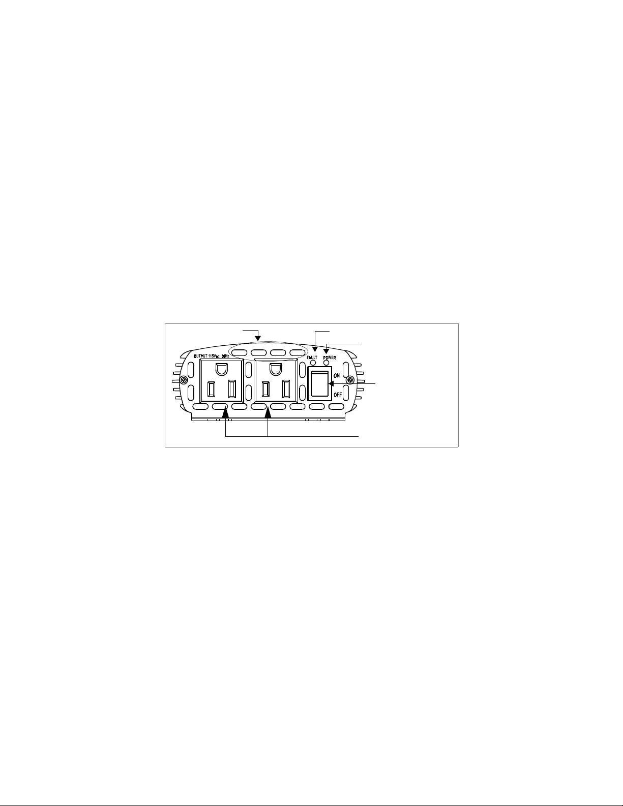
Figure 1 shows the AC panel of the PROwatt 400 inverter.
Ventilation
Openings
Figure 1 AC Panel of PROwatt 400
AC Outlets
Two AC receptacles are located on one end of the
Fault light
Power light
On/Off switch
AC Outlets
PROwatt 400. You can plug in any combination of 115 Vac appliances
with a total power consumption of 150 watts or less when the inverter is
plugged into a vehicle’s lighter socket. Or you can plug in appliances
with a total power consumption of 400 watts or less when the inverter is
hardwired to a battery.
5
Page 10

On/Off Switch
When the On/Off switch is on, AC power is available at
the outlets. The switch also acts as a manual reset for overload, low
battery voltage, and over temperature conditions.
POWER
Light
The green
POWER
light indicates that AC power is
present at the outlets and that the PROwatt 400 is operating normally.
FAULT
Light
The red
light indicates that the inverter has shut
FAULT
down. Shutdown is caused by low or high battery voltage, overload, or
excessively high temperatures.
Audible Alarm
An audible alarm warns of an impending low voltage
shutdown.
Ventilation Openings
To prevent overheating, ensure that the
ventilation openings on the front and back panels are kept clear.
6
Page 11
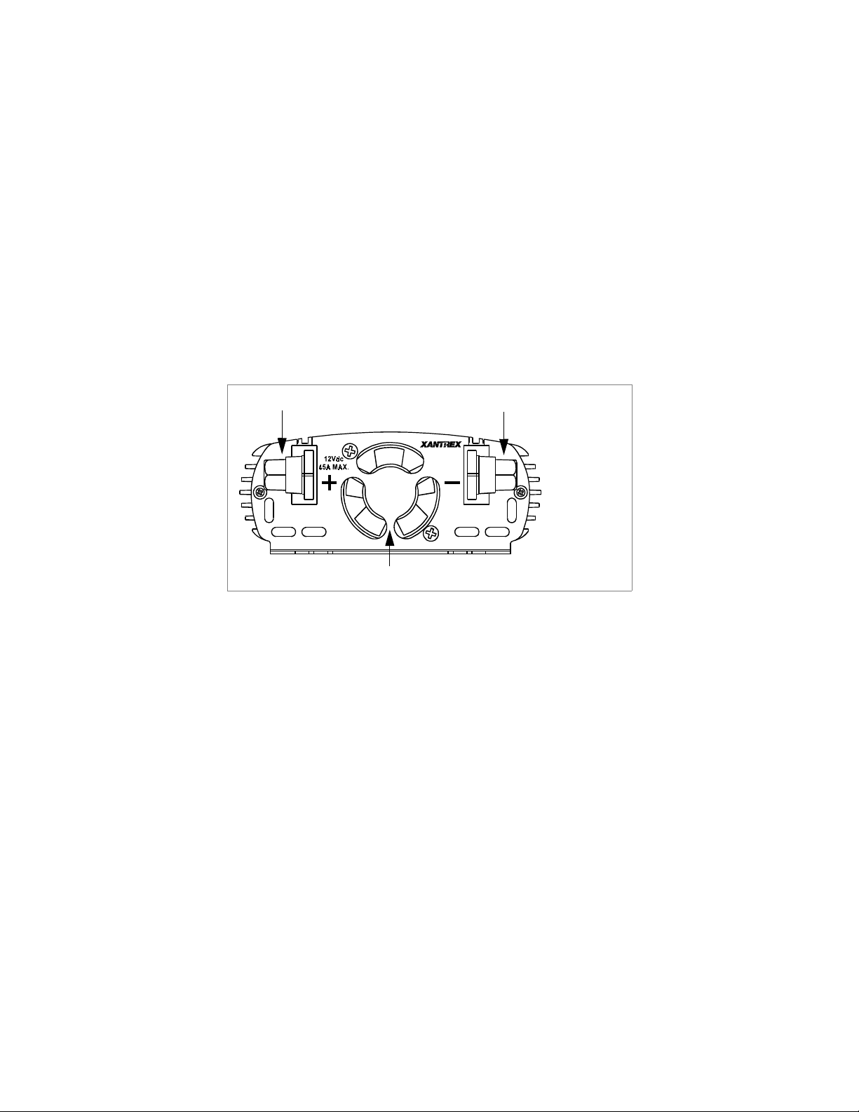
DC (Back) Panel
Figure 2 shows the DC panel of the PROwatt 400 inverter.
Positive cabling terminal
Fan and ventilation openings
Figure 2 DC Panel of PROwatt 400
Fan and Ventilation Openings
The fan runs continuously while the
Negative cabling terminal
inverter is on. If the inverter overheats, let the fan run to cool it down.
However, if the inverter is in low-voltage shutdown mode as indicated
by the audible alarm, turn the inverter off to conserve battery capacity.
Positive and Negative Cabling Terminals
You connect the ring
terminals on the power cables to these terminals. To ensure correct
polarity, red must be connected to red and black must be connected to
black.
7
Page 12
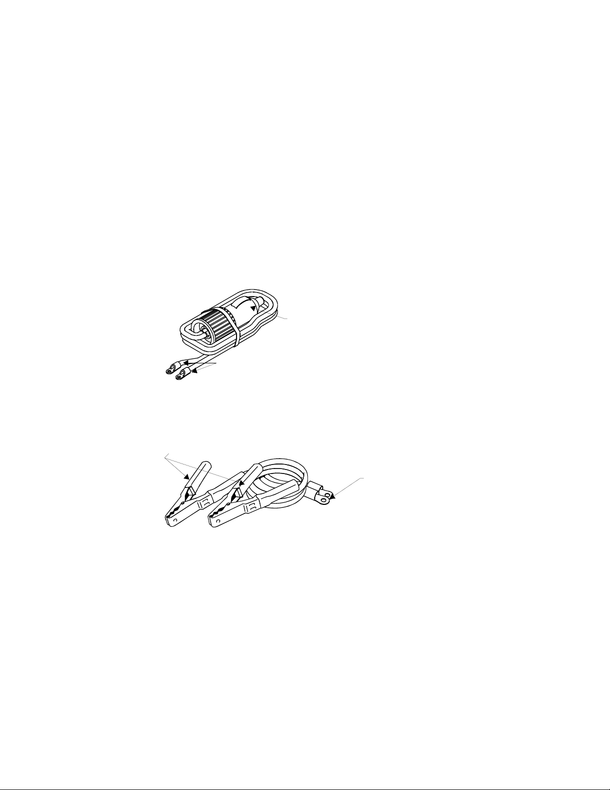
Lighter Plug Cable
Figure 3 shows the lighter plug cable that you use when you are going to
power loads less than 150 watts.
Lighter Plug
Ring Terminals:
color-coded red (+)
and black (–)
Figure 3 Lighter Plug Cable
Cable For Direct Connection to Battery
Figure 4 shows the cable you install when the highest loads you are
going to power are greater than 150 watts.
Battery Clips: color-coded red (+) and black (–)
Ring Terminals:
color-coded red (+)
and black (–)
Figure 4 Cable for Direct Connection to 12 Volt Battery
8
Page 13

4 Connecting the PROwatt 400
This section gives guidelines for choosing a suitable location for the
PROwatt 400 and also gives procedures for:
• Connecting the PROwatt 400 to your vehicle’s 12 volt power
receptacle
• Connecting the inverter directly to the vehicle’s battery
Caution!
The PROwatt 400 must only be connected to a battery that
has a nominal output of 12 volts. It will not operate if
connected to a 6 volt battery and will be damaged if
connected to a 24 volt battery.
Determining Power Requirements
You will need to find the power requirement of each appliance you want
to run to determine if you should connect the PROwatt 400 to a 12 volt
power receptacle (cigarette lighter socket) or directly to the vehicle
battery. If the total watts of all appliances will always be less than 150
watts you can use a 12 volt power receptacle; otherwise you must
connect the inverter directly to the battery.
You can find the power requirements of an appliance recorded on a label
located near the power cord. Add up the watts of all the appliances you
will be running at one time. The total shouldn’t be more than 400 watts.
9
Page 14

Choosing a Location
For the best performance, place the inverter in a location that is:
Dry Do not allow water or other liquids to splash on the
inverter.
Cool Ambient temperatures should be between 32° F and
100° F (0° C and 40° C)—the cooler the better
within this range. Keep the inverter away from
heating vents.
Well ventilated Allow at least 2 inches (5 cm) of clearance all around
the inverter, and keep the ventilation openings clear.
Clean Use the inverter in a clean environment.
Dust, metal shavings, smoke, soot, exhaust, and
other airborne contaminants may cause the unit to
fail.
10
Page 15

Connecting the PROwatt 400 for Loads Under 150
Watts
Follow these steps to connect the PROwatt 400:
1. Place the inverter on a flat surface like the floor of your vehicle.
2. Make sure the On/Off switch on the front panel is off.
3. Take the power cord equipped with the lighter plug (Figure 3) and
place the ring terminals over the two cabling terminals on the back
of the inverter. (The cabling terminals are shown in Figure 2.)
Make sure you connect red to red and black to black, and make sure
you screw the nuts on tightly.
4. Place the inverter’s plug in the vehicle’s cigarette lighter socket or a
12 volt outlet.
5. Turn on the front panel On/Off switch.
The green
operating normally and that AC power is available at the outlets.
6. Plug in the AC loads you want to operate.
POWER
light indicates that the PROwatt 400 is
11
Page 16

Connecting the PROwatt 400 for Loads Over 150
Watts
You must connect the PROwatt 400 directly to a 12 volt battery if you
are going to operate loads greater than 150 watts. (When the inverter is
connected this way, you can operate loads of any size up to 400 watts.)
Warni ng!
Batteries contain corrosive materials and present an
electrical shock hazard. To prevent irritation and burns, wear
protective eyewear and clothing when you install the inverter
or work with the batteries. Take special care to ensure that
metal tools and personal metal objects like rings and
bracelets do not contact the battery terminals.
Follow these steps to make a direct battery connection:
1. Place the inverter on a flat surface.
2. Make sure the On/Off switch on the front panel is off.
Caution! Reverse Polarity
Power connections to the PROwatt 400 must be
positive to positive and negative to negative.
A reverse polarity connection (positive to negative) will
blow a fuse in the inverter and may permanently
damage the unit. Damage caused by a reverse polarity
connection is not covered by your warranty.
12
Page 17

3. Take the cables equipped with battery clips on one end (Figure 4)
and place the ring terminals over the two cabling terminals on the
back of the inverter. (The cabling terminals are shown in Figure 2.)
Make sure you connect red to red and black to black, and make sure
you screw the nuts on tightly.
Warning! Explosion or fire hazard
Ensure there are no flammable gases or flammable materials
close by when you connect the positive clip to the battery
post. The connection may cause sparks.
4. Fasten the negative (black) clip to the negative battery post.
5. Double check that the polarity is correct.
6. Fasten the positive (red) clip to the positive battery post.
You may see sparks as you make the connection.
7. Turn on the front panel On/Off switch.
The PROwatt 400 is now ready for operation.
The green
POWER
light indicates that AC power is available at the
outlets and that the inverter is operating normally.
8. Plug in the AC loads you want to operate.
9. If you disconnect the battery, turn the inverter off first.
13
Page 18

5 Operating the PROwatt 400
This section explains how to operate the PROwatt 400 most efficiently.
Operating Conditions and Guidelines
This section describes normal operation as well as conditions that
trigger an alarm or automatically shut down the PROwatt 400.
Normal Operation
volt outlet and turn on the On/Off switch, the
and AC power is available at the outlets.
Low Battery Alarm and Shutdown
voltage decreases. When the PROwatt 400 senses that the voltage at its
DC input has dropped to 10.7 volts, it sounds an alarm. If you ignore the
alarm, at 10.0 volts the inverter shuts down all loads to save the battery
from further discharge. The
comes on.
Overload Shutdown
watts / 1.25 amps or a load that draws excessive surge power, the
PROwatt 400 shuts down. The
light comes on, indicating that the inverter is overloaded. The alarm
may also sound.
Over Temperature Shutdown
automatically if it exceeds its safe operating temperature. The
light goes out and the
When you connect the inverter to the vehicle’s 12
POWER
light illuminates
As the battery discharges, its
POWER
light goes out, and the
FAULT
light
If you connect an AC load rated higher than 150
POWER
light goes out and the
FAULT
The PROwatt 400 shuts down
POWER
light comes on.
FAULT
14
Page 19

High Input Voltage Shutdown
If a defective battery charging system
causes the battery voltage to rise to dangerously high levels, the
PROwatt 400 shuts down automatically. The
the
Manual Reset After Automatic Shutdown
FAULT
light comes on.
POWER
light goes out and
If any of the conditions listed on page 14 has caused an automatic
shutdown, correct the problem (for example, remove the loads or allow
the inverter to cool) and then reset the inverter. See “Troubleshooting
Reference” on page 20 for specific problems and solutions.
To reset the inverter, turn the On/Off switch off for 5 seconds, and then
turn it on again. This manual reset feature prevents unexpected or
hazardous restarting of connected AC loads.
Shutting the Inverter Off
• If you are going to disconnect the battery, turn the inverter off first.
• Turn the inverter off using the front panel On/Off switch.
Operating Normal Loads
The PROwatt 400 can power most loads within its rating (400 watts /
3.5 amps). Some appliances, however, may be difficult or impossible to
operate. Please read “Operating Loads With High Surge Requirements”.
Operating Loads With High Surge Requirements
The power, or wattage, rating of AC loads is the average amount of
power they use. Some appliances consume more power than their power
rating when they are first turned on. TVs, monitors, and electric motors
are some products that have high surge requirements at start up.
15
Page 20

Although the PROwatt 400 can supply momentary surge power to 800
watts, some products rated less than 400 watts may exceed its surge
capability and trigger an overload shutdown.
16
Page 21

6 Maintaining Battery Condition
The battery operating time of the PROwatt 400 depends on the charge
level of the battery, battery capacity, and the amount of power drawn by
the AC loads you are operating. With a typical vehicle battery and a 400
watt load, you can expect one or more hours of operating time.
Here are some guidelines that will help to preserve your battery:
• Vehicle batteries are not designed for repeated deep-discharge
cycles, and constantly recharging a vehicle’s battery will shorten its
life. Therefore, when you are using a vehicle battery as a power
source, start the vehicle every hour or two to recharge the battery.
Caution!
The PROwatt 400 will operate while the engine is
running, but the voltage drop that occurs when the
engine starts may trigger a low voltage shutdown.
• If you are not going to use the PROwatt 400 for more than a week,
turn off the On/Off switch. The inverter draws less than 0.21 amps
when the On/Off switch is on and no load is connected, but it will
eventually discharge the battery.
17
Page 22

7 Troubleshooting
This section will help you identify the source of most problems that can
occur with the PROwatt 400.
If you have a problem with the inverter, please review this section
before contacting Xantrex Customer Service. If you are unable to solve
a problem and need to contact Xantrex, please prepare for the call by
writing down the following details:
• Inverter’s serial number
• How long the inverter has been in use
• Where it is installed
• Appliances operating when the problem occurred
• A brief description of the problem
If you do require warranty service, you will be asked for proof of
purchase.
18
Page 23

Common Problems
Warning! Electrical Shock and Burn Hazard
Do not dismantle the PROwatt 400. It does not contain any
user-serviceable parts. Attempting to service the inverter
yourself could result in an electrical shock or burn.
Buzz in Audio Systems
Some inexpensive stereo systems have inadequate internal power
supply filtering and buzz slightly when powered by the PROwatt 400.
The best solution is to use an audio system with a good quality filter.
Television Interference
The PROwatt 400 is shielded to minimize interference with TV signals.
If TV signals are weak, you may see interference in the form of lines
scrolling across the screen. Try one of these suggestions to minimize or
eliminate the problem:
• Use an extension cord to increase the distance between the
PROwatt 400 and the TV, antenna, and cables.
• Adjust the orientation of the PROwatt 400, television, antenna, and
cables.
• Maximize TV signal strength by using a better antenna, and use
shielded antenna cable where possible.
• Try a different TV. Different models vary considerably in their
susceptibility to interference.
19
Page 24

Troubleshooting Reference
This section describes problems, their symptoms, possible causes, and
specific remedies.
The AC load will not operate. The
Symptom
to ten seconds, and then the
Possible Cause Suggested Remedy
The AC load is rated at more
than 400 watts; the safety
overload circuit has tripped.
The AC load is rated at less than
400 watts; a high starting surge
has tripped the overload circuit.
The AC load is plugged in or turned on and operates for one
FAULT
Use a product with a power rating lower
than 400 watts (or 120 volts / 2.5 amps).
The product exceeds the inverter’s surge
capability. Use a product with a starting
surge power within the PROwatt 400’s
capability.
FAULT
light is on.
light illuminates.
Symptom
The AC load does not operate. The
FAULT
light comes on
when the inverter is turned on, or when the load is turned on or plugged
in, and the alarm may sound.
Possible Cause Suggested Remedy
The battery is discharged. Recharge the battery.
Excessive battery voltage Check the charging system.
The load exceeds the 150 watt
rating for the lighter socket.
20
Hardwire the inverter to the battery as
explained on
page 12
.
Page 25

Symptom
FAULT
Possible Cause Suggested Remedy
Poor ventilation has caused the
PROwatt 400 to overheat.
The load is greater than 400 W or
the ambient temperature is above
25 °C.
The AC load runs for more than one minute, and then the
light turns on. The inverter is warm or hot to touch.
Ensure that ventilation is not restricted
around the inverter and allow it to cool for
ten minutes with the fan running. After ten
minutes, turn the inverter off, and then turn
it on again after five seconds.
Reduce the load or ambient temperature.
Allow the unit to cool, then turn it on again.
The AC load will not operate. No inverter lights are on.
Symptom
Possible Cause Suggested Remedy
Poor contact with the lighter
socket or 12 volt outlet.
The inverter has been connected
with reverse DC input polarity.
The lighter works in the lighter socket; the inverter does not.
Press the plug firmly into the socket. Clean
the plug or socket if necessary.
The inverter has likely been damaged and
needs to be repaired. Read the instructions
for returning the inverter on page 27
.
21
Page 26

Symptom
Possible Cause Suggested Remedy
The lighter socket or 12 volt
outlet may need to have the
ignition switched on.
The cigarette lighter or the
12 volt outlet fuse is blown.
The lighter does not work in the lighter socket.
Turn the key to the accessory position.
Check the vehicle fuses and replace blown
fuses with the correct value.
Measured inverter output is too low.
Symptom
Possible Cause Suggested Remedy
A standard “average-reading”
AC voltmeter has been used to
measure output voltage.
The battery voltage is too low. Recharge the battery.
The volt meter reading is 5 to 15 volts too low.
For accurate measurement, the
PROwatt 400 modified sine wave output
requires a “true RMS” voltmeter, such as a
Fluke 87 series multimeter.
Battery run time is less than expected.
Symptom
FAULT
Possible Cause Suggested Remedy
The AC load power consumption
is higher than rated.
The inverter runs for a while, the alarm sounds and then the
light illuminates. The inverter is cool or warm to touch.
Use a larger battery to make up for the
increased power requirement.
22
Page 27

Possible Cause Suggested Remedy
The battery is old or defective. Replace the battery.
The battery is not being charged
properly.
Have your vehicle electrical system
checked by a qualified technician.
23
Page 28

8 Specifications
Specifications are subject to change without notice.
AC output voltage (nominal) 115 Vac RMS ±10Vac
DC input voltage range 10–15 volts DC
Maximum continuous AC output power 400 watts
Maximum AC output surge power 800 watts
AC output frequency 60 ± 4 Hz
AC output waveform Modified Sine Wave
No load current draw (at 12 V input) 0.21 amps
Efficiency (maximum) 90%
Ambient operating temperature range 32° F–100° F
Low voltage alarm At 10.7 volts
Low voltage shutdown At 10.0 volts
Over temperature shutdown Yes, automatic
Overload shutdown Yes, automatic
High battery shutdown point (nominal) 15 volts
AC receptacles 2
Dimensions (L x W x H) 6.3 x 4.7 x 1.8 in
Weight 2.0 lb / 920 grams
0° C–40° C
160 x 120 x 46 mm
24
Page 29

9 Warranty Information
What Does This Warranty Cover?
from parts and components that are new or equivalent to new, in
accordance with industry standard practices. This warranty covers any
defects in workmanship or materials.
How Long Does The Coverage Last?
year from the date of purchase. Implied warranties of merchantability
and fitness for a particular purpose are limited to one year from date of
purchase. Some jurisdictions do not allow limitations on how long an
implied warranty lasts, so the above limitation may not apply to you.
What Does This Warranty Not Cover?
where the product has been misused, neglected, improperly installed,
physically damaged or altered, either internally or externally, or
damaged from improper use or use in an unsuitable environment.
Xantrex does not warrant uninterrupted operation of its products.
Xantrex shall not be liable for damages, whether direct, incidental,
special, or consequential, or economic loss even though caused by the
negligence or fault of Xantrex. Some jurisdictions do not allow the
exclusion or limitation of incidental or consequential damages, so the
above limitation or exclusion may not apply to you.
What Will Xantrex Do?
the defective product free of charge. Xantrex will, also at its option, use
new and/or reconditioned parts made by various manufacturers in
performing warranty repair and building replacement products. If
Xantrex repairs or replaces a product, its warranty term is not extended.
Xantrex owns all parts removed from repaired products.
At its option, Xantrex will repair or replace
Xantrex manufactures its products
This warranty lasts for one (1)
This warranty will not apply
25
Page 30

Service During Warranty
In order to qualify for the warranty, a dated
proof of purchase must be provided and the product must not be
disassembled or modified without prior authorization by Xantrex. If
your product requires warranty service, please return it to the place of
purchase along with a copy of your dated proof of purchase. If you are
unable to contact your merchant, or the merchant is unable to provide
service, contact Xantrex directly:
Phone (toll free):1-800-670-0707
Fax: 604 420-2145
Fax (toll free): 1-800-994-7828
Email: support.prowatt@xantrex.com
26
Page 31

Returning a Product
You must obtain a Return Material Authorization (RMA) number from
Xantrex before returning a product directly to Xantrex. When you
contact Xantrex to obtain service, be prepared to supply the following
information:
• Serial number of your inverter
• Date of purchase
• Information about the installation and use of the inverter
If you are returning a product from the USA or Canada, follow this
procedure:
1. Obtain an RMA number and a shipping address from Xantrex.
Products returned without an RMA number or shipped collect will
be refused.
2. Package the inverter safely, preferably using the original packing
materials. Include the following with your shipment:
• The RMA number
• A copy of your dated proof of purchase
• A return address where the repaired unit can be shipped
• A contact telephone number
• A brief description of the problem
3. Ship the inverter to the address provided in Step 1, freight prepaid.
Xantrex recommends that you obtain proof of delivery.
27
Page 32

How Other Laws Apply
This warranty gives you specific legal rights,
and you may also have other rights which vary from jurisdiction to
jurisdiction.
For Our Canadian Customers
When used herein “implied warranties
of merchantability and fitness for a particular purpose” includes all
warranties and conditions, express or implied, statutory or otherwise,
including without limitation implied warranties and conditions of
merchantability and fitness for a particular purpose.
28
Page 33

Out of Warranty Service
If the warranty period for your PROwatt 400 has expired, if the inverter
was damaged by misuse or incorrect installation, if other conditions of
the warranty have not been met, or if no dated proof of purchase is
available, your inverter may be serviced or replaced for a flat fee.
To return your PROwatt 400 for out of warranty service, contact
Xantrex Customer Service for a Return Material Authorization (RMA)
number and follow the other steps outlined in “Service During
Warranty” on page 26.
Payment options such as credit card or money order will be explained
by the Customer Service Representative. In cases where the minimum
flat fee does not apply, as with incomplete inverters or inverters with
excessive damage, an additional fee will be charged. If applicable, you
will be contacted by Customer Service once your inverter has been
received.
29
Page 34

10 Other Xantrex Products
To see the range of inverters and chargers offered by Xantrex, visit our
web site at http://www.xantrex.com
30
Page 35

Index
A
AC outlets 5
alarm, low battery
appliances
battery-operated
camcorders
cell phone chargers
fluorescent lights
laptop computers
rechargeable flashlights
rechargeable shavers
soldering irons
TVs
1
VCRs
1
1
1, 6, 14,
4
1
B
batteries
discharged
maintaining condition
nickel-cadmium
recharging
20
17,
22
4
replacing
vehicle
20
23
17
C
cable (for connection to battery)
connecting
1
1
1
4
4
17
illustrated
cable (lighter plug)
connecting
illustrated
cabling terminals
camcorders
chargers
cam corders
cell phone
computers, laptop
13
8
11
8
7
1
1
1
1
31
Page 36

F
fan 7
FAULT light
flashlights, rechargeable
fuses
6, 14, 20–
22
22
L
lights, fluorescent 1
loads
normal
with high surge requirements
low current draw
15
17
O
On/Off switch 6
P
polarity 12, 13, 21
POWER light
PROwatt
manual reset
out of warranty service
PROwatt 400
automatic shutdown
32
6, 11, 13,
15
1,
choosing a location
connecting to battery
connecting to lighter plug
4
15
14
29
14
current draw
disconnecting the battery
features
illustration of AC panel
illustration of DC panel
normal operation
overheating
reset after shutdown
returning to Xantrex
serial number
shutting inverter off
specifications
warranty
5
21
25
R
reset after shutdown 15
Return Material Authorization
number
reverse polarity
10
12
17
14
15
27
18
15
24
27
7, 12, 13,
11
15
5
7
21
Page 37

S
safety guidelines 3
serial number
service
during warranty
out of warranty
shavers, rechargeable
shutdown
high voltage
low battery
low voltage
over temperature
overload
soldering irons
specifications
surge power
18,
1, 15,
14
1,
1, 14,
1
24
14,
17
15
27
26
29
1,
20
T
troubleshooting
audio systems
overview
reference
television interference
TVs
1
19
18
20
4
20
14
V
VCRs 1
ventilation
ventilation openings
10,
21
6
W
warranty 25
X
Xantrex
email
26
fax number (toll free)
phone number
web site
19
30
26
26
33
Page 38

34
 Loading...