

Page 1

PROwatt 3000 Inverter
Owner’s Guide
Page 2

About Xantrex
Xantrex Technology Inc. is a world-leading supplier of advanced power electronics and controls
with products from 50 watt mobile units to 1 MW utility-scale systems for wind, solar, batteries,
fuel cells, microturbines, and backup power applications in both grid-connected and standalone
systems. Xantrex products include inverters, battery chargers, programmable power supplies, and
variable speed drives that convert, supply, control, clean, and distribute electrical power.
Trademarks
PROwatt is a trademark of Xantrex International. Xantrex is a registered trademark of
Xantrex Technology Inc.
Other trademarks, registered trademarks, and product names are the property of their respective
owners and are used herein for identification purposes only.
Notice of copyright
PROwatt 3000 Inverter Owner’s Guide © November 2001 Xantrex International. All rights
reserved.
Disclaimer
UNLESS SPECIFICALLY AGREED TO IN WRITING, XANTREX TECHNOLOGY INC.
(“XANTREX”)
(a) MAKES NO WARRANTY AS TO THE ACCURACY, SUFFICIENCY OR SUITABILITY OF ANY
TECHNICAL OR OTHER INFORMATION PROVIDED IN ITS MANUALS OR OTHER
DOCUMENTATION.
(b) ASSUMES NO RESPONSIBIL ITY OR LIABIL ITY FOR LO SS OR DAMAGE, WH ETHER DIRE CT,
INDIRECT, CONSEQUENTIAL OR INCIDENTAL, WHICH MIGHT ARISE OUT OF THE USE OF
SUCH INFORMATION. THE USE OF ANY SUCH INFORMATION WILL BE ENTIRELY AT THE
USER’S RISK.
Date and Revision
November 2001, Revision 1
Part number
445-0118-01-01
Contact Information
W eb: www .xantrex.com
Email: support.prowatt@xantrex.com
Phone: 1-800-670-0707
Fax: 1-800-994-7828
Page 3

About This Guide
Purpose
The PROwatt 3000 Inverter Owner’s Guide contains information that
enables individuals to install, operate, and troubleshoot the
PROwatt™ 3000 Inverter.
Scope
The guide provide s safety gu idelin es, deta iled in formation for des igning
an installation, procedures for installing the inverter, as well as
information about operating and troubleshooting the unit. It does not
provide details about particular brands of batteries. You need to consult
individual battery manufacturers for this information.
Audience
The guide is intended for anyone who needs to install and operate the
PROwatt 3000. Installers should be certified technicians or electricians.
Organization
This guide is organized into five chapters, five appendixes, and an
index.
Chapter 1, “Introduction” , outlines the main p erformance and saf ety
features of the PROwatt 3000. Reading this chapter will give you a
clear understanding of the inverter’s capabilities.
Chapter 2, “PROwatt 3000 Features”, outlines the main physical
features of the inverter and the components that are shipped with it.
This chapter will give you a good orientation to the product before
you install it.
iii
Page 4

About This Guide
Chapter 3, “Installation”, begins by explaining how to plan an
effective installation. (Read this chapter in conjunction with
Appendix C and Appendix D. ) It goes on to give deta iled procedures
for installing the inverte r.
Chapter 4, “Operation”, provides information for turning on and
operating the inverter. Details are provided about how to read the
front panel indicators to monitor system performance. The chapter
also provides information about battery charging frequency and
routine maintenance.
Chapter 5, “Troubleshooting”, explains how to solve problems that
can occur with the inverter.
Appendix A, “Specifications”, provides electrical, physical, and
performance specifications for the inverter and physical
specifications for the remote On/Off switch.
Appendix B, “Alternators and Charging Systems”, describes the
components in charging systems and explains how to design a
charging system for your installation.
Appendix C, “Battery Types and Sizes”, provides background
information about batt ery t ypes a s well as i nforma tion t hat wi ll h elp
you calculate the size and number of batteries your system requires.
Appendix D, “Product and System Information”, contains the
product’s warranty , explains how to ret urn a prod uct for s ervice, and
describes how to prepare for a call to Xantrex Customer Service.
The Index provides a valuable means of looking up specific
information topics and tasks.
iv
Page 5

Conventions Used
The following conventions are used in this guide.
WARNING
Warnings identify conditions that could result in personal
injury or loss of life.
CAUTION
Cautions i dentify conditions or practices that could result in
damage to the PROwatt 3000 or other equipment.
Note: Notes describe additional information which may add to your
understanding of how to use the inverter.
Related Information
About This Guide
You can find more information about Xantrex Technology Inc. as well
as its products and services at www.xantrex.com
v
Page 6

vi
Page 7

Contents
Important Safety Information
General Precautions - - - - - - - - - - - - - - - - - - - - - - - - - - - - - - - - - - - - - - - - - - xi
Explosive Gas Precaution s- - - - - - - - - - - - - - - - - - - - - - - - - - - - - - - - - - - - - - xi
Precautions When Working With Batteries - - - - - - - - - - - - - - - - - - - - - - - - - - xii
Precautions For Using Rech argeable Appliances- - - - - - - - - - - - - - - - - - - - - - - xii
1Introduction
Quality Pow er - - - - - - - - - - - - - - - - - - - - - - - - - - - - - - - - - - - - - - - - - - - - - 1–2
Ease of Use - - - - - - - - - - - - - - - - - - - - - - - - - - - - - - - - - - - - - - - - - - - - - - - 1–2
Comprehensive Protection- - - - - - - - - - - - - - - - - - - - - - - - - - - - - - - - - - - - - 1–3
2 PROwatt 3000 Features
Materials List - - - - - - - - - - - - - - - - - - - - - - - - - - - - - - - - - - - - - - - - - - - - - 2–2
Front Panel (AC End) - - - - - - - - - - - - - - - - - - - - - - - - - - - - - - - - - - - - - - - - 2–3
Front Panel With AC Receptacle - - - - - - - - - - - - - - - - - - - - - - - - - - - - - - - 2–4
Front Panel Showing AC Wiring Compartment - - - - - - - - - - - - - - - - - - - - - 2–6
Back Panel ( DC End) - - - - - - - - - - - - - - - - - - - - - - - - - - - - - - - - - - - - - - - - 2–7
Remote On/Off Switch - - - - - - - - - - - - - - - - - - - - - - - - - - - - - - - - - - - - - - - 2–8
3 Installation
Safety Instructions - - - - - - - - - - - - - - - - - - - - - - - - - - - - - - - - - - - - - - - - - - 3–2
Installatio n Codes - - - - - - - - - - - - - - - - - - - - - - - - - - - - - - - - - - - - - - - - - - 3–2
Installatio n Tools and Materials - - - - - - - - - - - - - - - - - - - - - - - - - - - - - - - - - 3–2
Tools- - - - - - - - - - - - - - - - - - - - - - - - - - - - - - - - - - - - - - - - - - - - - - - - - - 3–2
Materials - - - - - - - - - - - - - - - - - - - - - - - - - - - - - - - - - - - - - - - - - - - - - - - 3–2
Overview of Installation Steps - - - - - - - - - - - - - - - - - - - - - - - - - - - - - - - - - - 3–3
Designing Y our Installation- - - - - - - - - - - - - - - - - - - - - - - - - - - - - - - - - - - - 3–4
Calculating Battery Requ irements - - - - - - - - - - - - - - - - - - - - - - - - - - - - - - 3–4
Choosing a Charging System- - - - - - - - - - - - - - - - - - - - - - - - - - - - - - - - - - 3–4
Choosing a L ocation- - - - - - - - - - - - - - - - - - - - - - - - - - - - - - - - - - - - - - - - - 3–5
Connecting to an Existing AC Circuit - - - - - - - - - - - - - - - - - - - - - - - - - - - - - 3–6
vii
Page 8

Contents
AC Wiring Pr ecautions - - - - - - - - - - - - - - - - - - - - - - - - - - - - - - - - - - - - - 3–6
AC Wiring Pr ocedure- - - - - - - - - - - - - - - - - - - - - - - - - - - - - - - - - - - - - - - 3–7
Installing Transfer Switches in AC Circuits- - - - - - - - - - - - - - - - - - - - - - - - 3–9
Installing the Remote On/Of f Switch- - - - - - - - - - - - - - - - - - - - - - - - - - - - - 3–10
Mounting the Inverter - - - - - - - - - - - - - - - - - - - - - - - - - - - - - - - - - - - - - - - 3–11
Connecting the Chassis Ground - - - - - - - - - - - - - - - - - - - - - - - - - - - - - - - - 3–1 1
Grounding Locations - - - - - - - - - - - - - - - - - - - - - - - - - - - - - - - - - - - - - - 3–12
Connecting DC Cables - - - - - - - - - - - - - - - - - - - - - - - - - - - - - - - - - - - - - - 3–13
Cabling Guidelines - - - - - - - - - - - - - - - - - - - - - - - - - - - - - - - - - - - - - - - 3–13
DC Fuses - - - - - - - - - - - - - - - - - - - - - - - - - - - - - - - - - - - - - - - - - - - - - - 3–14
Cabling Procedure- - - - - - - - - - - - - - - - - - - - - - - - - - - - - - - - - - - - - - - - 3–14
4Operation
Turning the Inverter On and Off- - - - - - - - - - - - - - - - - - - - - - - - - - - - - - - - - 4– 2
Using the Remote On/Off Switch - - - - - - - - - - - - - - - - - - - - - - - - - - - - - - - - 4–2
Turning the Inverter Off Between Charges - - - - - - - - - - - - - - - - - - - - - - - - - - 4–2
Operating Several Loads at Once - - - - - - - - - - - - - - - - - - - - - - - - - - - - - - - - 4–3
Resetting the AC Circuit Breaker - - - - - - - - - - - - - - - - - - - - - - - - - - - - - - - - 4–3
Reading the Front Panel Indicators - - - - - - - - - - - - - - - - - - - - - - - - - - - - - - - 4–3
Battery Voltage Indicator - - - - - - - - - - - - - - - - - - - - - - - - - - - - - - - - - - - - 4–3
Battery Current Indicator - - - - - - - - - - - - - - - - - - - - - - - - - - - - - - - - - - - - 4–3
OVER TEMP Indicator (and Alarm) - - - - - - - - - - - - - - - - - - - - - - - - - - - - 4–4
OVER LOAD Indicator - - - - - - - - - - - - - - - - - - - - - - - - - - - - - - - - - - - - - 4–4
Operating L i mits - - - - - - - - - - - - - - - - - - - - - - - - - - - - - - - - - - - - - - - - - - - 4–4
Power Output - - - - - - - - - - - - - - - - - - - - - - - - - - - - - - - - - - - - - - - - - - - - 4–4
Input Voltage - - - - - - - - - - - - - - - - - - - - - - - - - - - - - - - - - - - - - - - - - - - - 4–5
Inverter Loads - - - - - - - - - - - - - - - - - - - - - - - - - - - - - - - - - - - - - - - - - - - - - 4–6
Problem Loads - - - - - - - - - - - - - - - - - - - - - - - - - - - - - - - - - - - - - - - - - - - 4–6
Trouble Loads- - - - - - - - - - - - - - - - - - - - - - - - - - - - - - - - - - - - - - - - - - - - 4–6
Battery Charging Frequency - - - - - - - - - - - - - - - - - - - - - - - - - - - - - - - - - - - 4–7
Routine Maintenance - - - - - - - - - - - - - - - - - - - - - - - - - - - - - - - - - - - - - - - - 4–7
5 Troubleshooting
Common Problems- - - - - - - - - - - - - - - - - - - - - - - - - - - - - - - - - - - - - - - - - - 5–2
Buzz in Audio Equipment- - - - - - - - - - - - - - - - - - - - - - - - - - - - - - - - - - - - 5–2
Television R eception - - - - - - - - - - - - - - - - - - - - - - - - - - - - - - - - - - - - - - - 5–2
Troubleshooting Reference - - - - - - - - - - - - - - - - - - - - - - - - - - - - - - - - - - - - 5–3
viii
Page 9

A Specifications
Electrical Performance (Inverter) - - - - - - - - - - - - - - - - - - - - - - - - - - - - - - - - A–2
Physical (Inverter) - - - - - - - - - - - - - - - - - - - - - - - - - - - - - - - - - - - - - - - - - - A–2
Dimensions (Remote On/O ff Switch) - - - - - - - - - - - - - - - - - - - - - - - - - - - - - A–2
Alternators and Charging Systems
B
Charging System Requirem ents - - - - - - - - - - - - - - - - - - - - - - - - - - - - - - - - - B–2
Charging With an Engine Alternator - - - - - - - - - - - - - - - - - - - - - - - - - - - - - - B–2
Using a Standard Vehicle Alt ernator- - - - - - - - - - - - - - - - - - - - - - - - - - - - - B–2
Using an Alternator Controller - - - - - - - - - - - - - - - - - - - - - - - - - - - - - - - - B–3
Using a High-Output Alternator- - - - - - - - - - - - - - - - - - - - - - - - - - - - - - - - B–3
Charging Fr om AC Power - - - - - - - - - - - - - - - - - - - - - - - - - - - - - - - - - - - - - B –3
Charging From Alternativ e Energy Sources - - - - - - - - - - - - - - - - - - - - - - - - - B–3
C
Battery Types and Sizes
Battery Types - - - - - - - - - - - - - - - - - - - - - - - - - - - - - - - - - - - - - - - - - - - - - C–2
Automotive Starting Batteries - - - - - - - - - - - - - - - - - - - - - - - - - - - - - - - - - C–2
Deep-Cycle Lead-Acid Ba tteries - - - - - - - - - - - - - - - - - - - - - - - - - - - - - - - C–2
Battery Size - - - - - - - - - - - - - - - - - - - - - - - - - - - - - - - - - - - - - - - - - - - - - - C–3
Estimating Battery Requirements - - - - - - - - - - - - - - - - - - - - - - - - - - - - - - - - C–4
Battery Sizing Example - - - - - - - - - - - - - - - - - - - - - - - - - - - - - - - - - - - - - C–4
Battery Sizing Worksheet - - - - - - - - - - - - - - - - - - - - - - - - - - - - - - - - - - - - C–5
Using Multiple Batteries - - - - - - - - - - - - - - - - - - - - - - - - - - - - - - - - - - - - - - C–6
Two Batteries Connected In Parallel- - - - - - - - - - - - - - - - - - - - - - - - - - - - - C–6
Two Separate Battery Banks - - - - - - - - - - - - - - - - - - - - - - - - - - - - - - - - - - C–7
Battery Tips - - - - - - - - - - - - - - - - - - - - - - - - - - - - - - - - - - - - - - - - - - - - - - C–8
Contents
D
Product and Syst em In fo rma t ion
Warranty - - - - - - - - - - - - - - - - - - - - - - - - - - - - - - - - - - - - - - - - - - - - - - - - D–2
Return Mater ial Authorizatio n Policy - - - - - - - - - - - - - - - - - - - - - - - - - - - - - D–3
Return Material Procedure- - - - - - - - - - - - - - - - - - - - - - - - - - - - - - - - - - - - - D–3
Information About Your System- - - - - - - - - - - - - - - - - - - - - - - - - - - - - - - - - D–4
Remote On/Off Switch Mounting Template - - - - - - - - - - - - - - - - - - - - - - - - - D–5
Index - - - - - - - - - - - - - - - - - - - - - - - - - - - - - - - - - - - - - - - - - - Index–1
ix
Page 10

x
Page 11

Important Safety Information
WARNING
Before installing and using you r PROwatt
sure to read and save these safety instructions.
General Precautions
1. Before installing and us ing the invert er , read all appr opriate sect ions
of this guide as well as all instructions and cautionary markings on
the inverter and the batteries.
2. Do not operate the inverter if it has received a sharp blow, been
dropped, or otherwis e damaged. If the unit is damaged, see “Product
and System Information” on page D–1 and “Return Material
Authorization Policy” on page D–3.
3. Do not dismantle the inverter; it contains no user-serviceable
components. Attempting to service the unit yourself could cause
electrical shock or fire. Internal capacitors remain charged after
all power is disconnected.
™
3000 Inverter , be
4. T o reduce th e risk of elect rical sho ck, disconnec t AC and DC power
from the inverter before working on any circuits connected to the
inverter. Turning off controls will not reduce this risk.
5. Do not expose the inverter to rain, snow, spray, or bilge water.
6. To reduce the risk of overheating or fire, do not obstruct the
ventilation openings, and do not install the inverter in a zeroclearance c ompartment.
Explosive Gas Precautions
1. Batteries generate explosive gases during normal operation. Be sure
to read this guide and follow the instructions exactly before
installing or using your inverter.
2. This equipment contains co mponents which tend to produce arcs or
sparks. To prevent fire or explosion, do not install the inverter in
compartments containing batteries or flammable materials or in
xi
Page 12

Important Safety Information
locations that require ignition-protected equipment. This includes
any space containing gasoline-powered machinery, fuel tanks, as
well as joints, fittings , or othe r co nnections between components of
the fuel system.
Precautions When Working With Batteries
1. Follow all instructions published by the battery manufacturer and
the manufac turer of the equ ipment in which the battery is in stalled.
2. Make sure the area around the battery is well ventilated.
3. Never smoke or allow a spark or flame near the engine or batteries.
4. Use caution to reduce the risk of dropping a metal tool on the
battery. It could spark or short circuit the battery or other electrical
parts and could cause an explosion.
5. Remove metal items like rings, bracelets, and watches when
working with lead-acid batteries. Lead-acid batteries produce a
short-circuit curr ent high enough to weld a ring or the like to metal,
and thus cause a severe burn.
6. If you need to remove a battery, always remove the ground terminal
from the battery fi rs t. Make sure all accessori es are off so you don’t
cause an arc.
Precautions For Using Rechargeable Appliances
Most battery-operate d equipment uses a se parat e char ge r or tra nsfor mer
that is plugged into an AC recept acle and produ ces a lo w voltage output.
If the label on the AC adapter or charger states that the adapter or
charger produces a low voltage AC or DC output (less than 30 volts),
the PROwatt 3000 can power this charger or adapter safely.
Some chargers for small nickel-cadmium batteries can be damaged if
connected to the PROwatt 3000. Do not use the followi ng with the
PROwatt 3000:
• Small battery-operated appliances like flashlights, razors, and night
lights that can be plugged directly into an AC receptacle to recharge
• Chargers for battery packs use d in hand po wer too ls. These c harg ers
display a warning label stating that dangerous voltages are present
at the battery terminals.
xii
Page 13

1
Introduction
Congratulations on your purchase of the
PROwatt 3000 Inverter! As part of the PROwatt
Inverter family, the PROwatt 3000 has been
designed to give you quality power, ease of use,
and outstanding reliability.
Please take a few moments t o read this chapter to
familiarize yourself with the PROwatt 3000’s
main performance and protection features.
Page 14

Introduction
Quality Power
The PROwatt 3000 is a premium-quali ty inverter de signed for heavy-du ty
AC loads or smaller, multiple AC loads including large microwaves, TVs,
VCRs, air compressors, larger power tools, and air conditioners. It can
often be used in place of a generator for large or intermittent loads.
• The PROwatt 3000 provides up t o 2500 wat ts of con tinuou s power o r
• The inverter’s high surge capability lets you handle many hard-to-
• The unit’s low standby battery demand means you don’t have to
• For more effici ent power use, the fan shuts down aut o mat ica ll y whe n
3000 watts for five minutes, making it ideal for large single loads,
intermittent loads, or multiple smaller loads.
start loads, including large TVs, refrigerators, and freezers.
worry about excessive drain on your battery if you leave the inverter
on for a few days. When the inverter is on but no power is being
supplied to a load, the inverter draws less than 600 mA from the
battery.
no loads are attached to the inverter.
Ease of Use
1–2
Superior features and rugged du rability have been combin ed with extrem e
ease of use:
• The unit is compact, light weight, and easy to install.
• You can power loads directly from the receptacle on the front panel,
or you can hardwire the unit into an existing AC electrical system
using the leads in the inverter’s wiring compartment.
• Easy-to-read indicators on the front panel let you monitor system
performance at a glance.
• The remote On/Off switch lets you control the inverter from a
convenient location—up to 20 feet (6 m) away—while the inverter
itself is mounted out of sight and close to the batteries.
Page 15

Comprehensive Protection
The PROwatt 3000 is equipped with numerous protection features to
guarantee safe and trouble-free operation:
Low battery alarm Alerts you if the battery has become discharged to
10.7 V or lower.
Low voltage shutdown Automatically shuts the inverter down if the
battery voltage drops below 10 V. This feature protects the battery from
being completely discharged.
High voltage shutdown Shuts the inverter down automatically if the
input voltage rises to 15 V or more.
Overload shutdown Shuts the unit down automatically if a short
circuit occurs or if the loads attached to the inverter exceed the operating
limits.
Over temperature shutdown Turns the inverter off if its temperature
rises above an acceptable level.
Comprehensive Protection
1–3
Page 16

1–4
Page 17

2
PROwatt 3000 Features
Chapter 2 describes the main features of the
PROwatt 3000. Xantrex recommends that you
familiarize yourself with them before installing
and operating the inverter.
Page 18

PROwatt 3000 Features
Materials List
Your PROwatt 3000 package includes:
•1 PROwatt
3000 Inverter
• 2 plastic terminal connect or covers (red for positive; black for
negative) with screws
• 1 cover plate to cover the wiring compartment on the AC end of the
inverter
• 1/2 inch cable clamp
• Wire nuts and crimp-on connectors for permanent connection to an
AC circuit
• 1 remote On/Off switch and a 20 foot (6 m) communications cable
• 1 owner’s guide
If any of these materials are missing or are unsatisfactory in any way,
please contact Customer Service:
Phone: 1-800-670-0707
Fax: 1-800-994-7828
Email: support.prowatt@xantrex.com
As soon as you unpack your inverter, be sure to record the product
information asked for on page D–4.
2–2
Page 19

Front Panel (AC End)
The front panel of the PROwatt 3000 can be configured in two ways:
• PROwatt 3000 is equipped with one 15 A circuit breaker- p r ote ct ed
receptacle on the fr ont pa nel as shown in Fig ure 2- 1. You can connect
loads to this receptacle.
• To derive maximum power from the PROwatt 3000, you can remove
the receptacle and hardwire the inverter to an AC source panel
through the front panel as shown in Figure 2-2. (For AC wiring
procedures, see “Connecting to an Existing AC Circuit” on page 3–
6.)
Front Panel (AC End)
2–3
Page 20
PROwatt 3000 Features
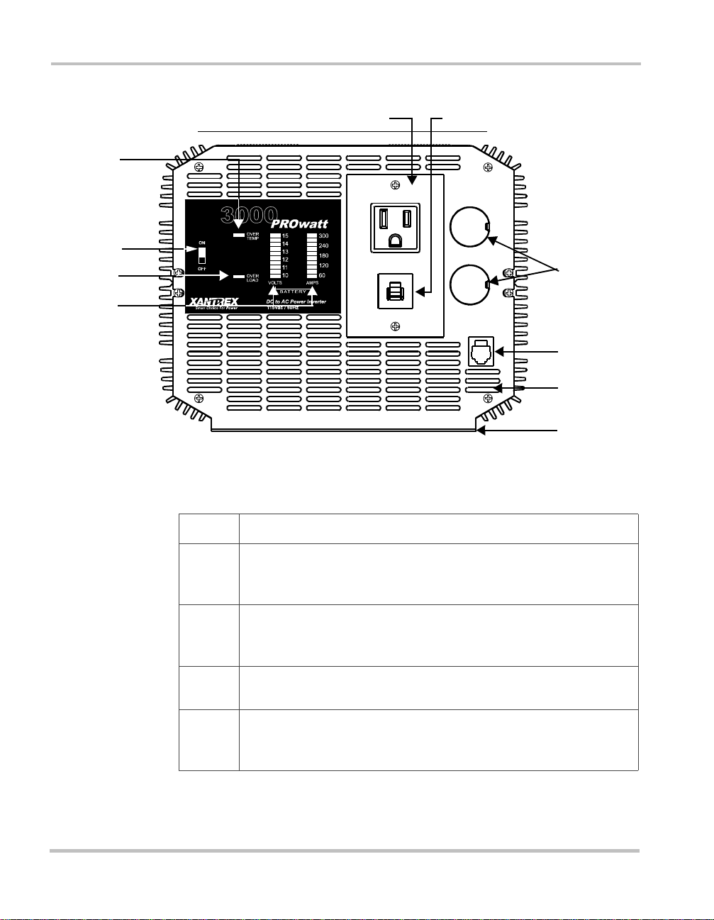
Front Panel With AC Receptacle
②
①
③
④
⑤
Figure 2-1 Front Panel With AC Receptacle
Feature Description
}
⑦
⑧
⑨
⑩
2–4
On/Off Switch This switch turns the inverter’s control circuit on and
➀➀➀➀
off. It is not a power disconn ect switch. You must disconnect AC and
DC power before working on any circuits connected to the inverter.
OVER TEMP Indicator This indicator lights when the inverter shuts
➁➁➁➁
down to protect itself from overheating. When the inverter cools, it
restarts automatically, and the indicator turns off.
OVER LOAD Indicator This indicator lights when the inverter shuts
➂➂➂➂
down because of an AC overload or a short circuit.
VOLTS and AMPS Indicators These display battery voltage and
➃➃➃➃
current. (See “Reading the Front Panel Indicators” on page 4–3 for
details.)
Page 21

Feature Description
AC Receptacle Delivers 15 amps (approximately 1700 watts) of
➄➄➄➄
continuous AC power. This is a grounded outlet with a 15 amp
circuit breaker . For full output power, you need to make a permanent
hardwire connection.
Circuit Breaker for AC receptacle
➅➅➅➅
Knockouts for AC wiring
➆➆➆➆
Remote Control Jack The jack allows you to connect the remote
➇➇➇➇
On/Off switch.
Ventilation Openings
➈➈➈➈
Mounting Flanges
➉➉➉➉
Front Panel (AC End)
2–5
Page 22

PROwatt 3000 Features
Front Panel Showing AC Wiring Compartment
①
②
③
2–6
Figure 2-2 Front Panel With AC Wiring Revealed
Feature Description
AC Wiring Compartment
➀➀➀➀
Outgoing AC Cable 10 AWG copper 2-conductor-plus-ground to
➁➁➁➁
AC distribution
Wire Nuts or Crimp-on Connectors (depending on the code that
➂➂➂➂
governs your installation)
Page 23
Back Panel (DC End)
Back Panel (DC End)
①
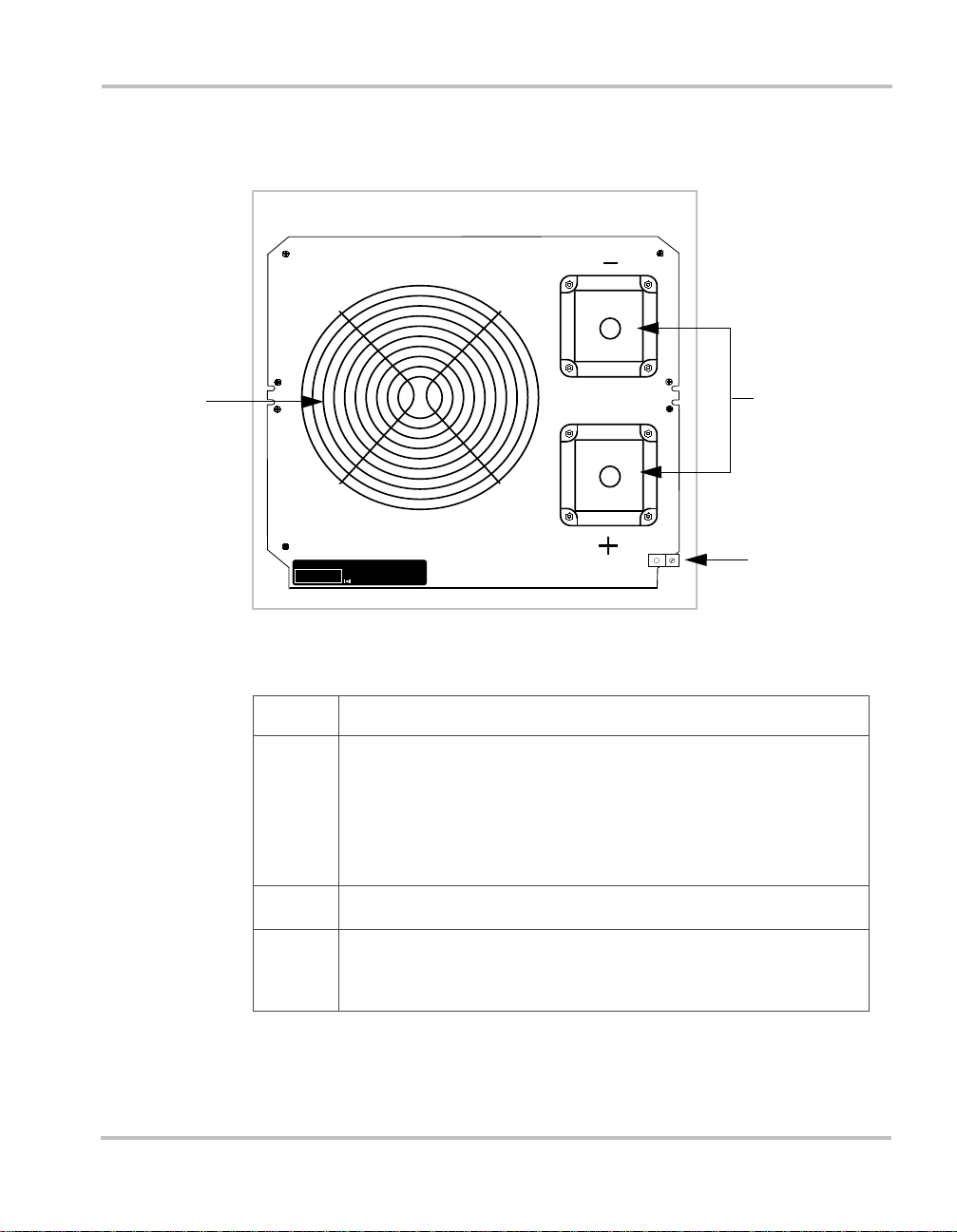
Figure 2-3 Back Panel: DC End
Feature Description
➀➀➀➀
➁➁➁➁
➂➂➂➂
Ventilation Openings For safety and proper operation of the
inverter, these openings (and the openings on the front of the
inverter) must not be obstructed. When the inverter is mounted,
these ventilation openings must not point up or down. In other
words, neither the front panel (AC en d) nor the b ack panel (D C end)
should point up or down.
Positive (Red) and Negative (Black) DC Cabling Terminals
Chassis Ground Lug Connects to earth ground, to vehicle chassis,
or to DC grounding bus or engine’s negative bus (in marine
installations).
②
③
2–7
Page 24

PROwatt 3000 Features
Remote On/Off Switch
REMOTE SWITCH
IN VERTER ON
➀
➁
➂
➃
2–8
Figure 2-4 Remote On/Off Switch
Feature Description
➀➀➀➀
➁➁➁➁
➂➂➂➂
➃➃➃➃
Switch Panel The 2 1/2 inch wide x 4 1/4 inch high (6.35 cm x
10.80 cm) panel mounts flush and requires 0.7 inches (18 mm) of
depth. See page 3–10 for installation instructions and Figure D-1
on page D–5 for a mounting template.
Cable and Connector The cable (20 feet; 6 m) is permanently
attached to the back of the switch. The connector plugs into the jack
on the front of the inverter. (Not shown.)
INVERTER ON Lights up when the inverter is on.
Touch control On/Off button
Page 25

3
Installation
Chapter 3 explains how to install the
PROwatt 3000.
Xantrex recommends that you read the entire
chapter so you can plan an installation that is
suited to your power needs and then complete the
installation procedures.
Page 26

Installation
Safety Instructions
Before you start to install the PROwatt 3000:
• Review the “Important Saf ety Information” on page xi.
• Do not attempt your own AC wiring unless you have the knowledge
and experience to do a safe job. Your RV dealer, boat dealer, or a
licensed electrician can install the inverter if you do not wish to do
your own wiring.
• Read and follow all Warnings and Cautions in this chapter.
Installation Codes
Governing installation codes vary depending on the location and type of
installation. Electrical installations must meet local and national wiring
codes and should be done by a qualified electrician.
Installation Tools and Materials
Tools
Materials
3–2
❐ Wire cutter
❐ Wire stripper
❐ Flat-head screwdriver
❐ Wrench for DC terminals
❐ Crimping tool for fastening lugs and terminals on DC cables. (You
may find it more convenient to have the c rimp conn ectors atta ched by
the company that sells you the cable.)
❐ Drill
❐ 4 corrosion-resistant fasteners sized #10 or larger for mounting the
inverter
❐ Copper DC cable, sized appropriately for load and application
❐ 2, 5/16 inch ring terminals sized for the cable diameter (or Ilsco or
equivalent box-lug terminals) to connect the DC ca ble s t o the inverter
Page 27

Overview of Installation Steps
❐ Lugs and terminals for the DC cables that connect to the battery and
fuse holder(s)
❐ DC fuse(s) and fuse holder(s)
❐ AC cable (2-conductor-plus-ground cable), sized appropriately for
load and application (if you are connecting to an existing AC circuit)
❐ 1/2 inch cable clamp (if connecting to an AC circuit)
❐ AC transfer switch (if connecting to an AC circuit that also uses
power from another AC source)
❐ Appropriately sized copper cable for the chassis ground
❐ Battery isolator (if connecting to a multiple-battery s ystem)
❐ Battery selector switch*
❐ Alternator controller*
❐ High-output alternator*
* Consult Appendix B, “Battery Types and Sizes” and Appendix C,
“Alternators and Char ging Syst ems” to determi ne whether y ou need thes e
components.
Overview of Installation Steps
Here’s a summary of the seven main steps:
1. Design the installation: calculate battery capacity and charging
requirements.
2. Choose a location.
3. Connect to an AC circuit (if required).
4. Install the remote On/Off switch.
5. Mount the inverter.
6. Connect the chassis ground.
7. Connect the DC cables.
3–3
Page 28

Installation
Designing Your Installation
Before doing anything else, determine how you are going to use your
PROwatt 3000, and on the basis of that, design a power system that will
give you maximum performance. The more thorough your planning, the
better your power needs will be met. In particular, you need to:
• Calculate your battery requirements
• Choose an effective charging system
Calculating Battery Requirements
Battery type and battery size strongly affect the performance of the
PROwatt 3000. Therefore, you need to identify the type of loads your
inverter will be powering and how much you will be using them between
charges. Once you know how much power you will be using, you can
determine how much battery capacity you need. Xantrex recommends
that you purchase as much battery capacity as possible.
Consult Appendix B, “Battery T y pes and Sizes” for a detailed explana tion
of how to determine the appropriate number and si ze of bat te ri es f or your
needs.
CAUTION
The PROwatt 3000 must only be connecte d to a batt ery th at has
a nominal output of 12 vo lts. It will no t ope rate if connect ed to a
6 volt battery and will be damaged if connected to a 24 volt
battery.
Choosing a Cha rging System
The charging system must be appropriate for your particular installation.
A well-designed char ging system wi ll ensure tha t power is avai lable when
you need it and that your batteries remain in top condition. Inadequate
charging will degr ade sy st em perf ormance , and the wr ong t ype of c har ger
will reduce battery life.
Consult Appendix C, “Alternators and Charging Systems” for
information about designing an effective charging system.
3–4
Page 29

Choosing a Location
WARNING
The PROwatt 3000 contains components that tend to produce
arcs or sparks. To prevent fire or explosion, do not install the
inverter in compartments containing batteries or flammable
materials or in locations that require ignition-protected
equipment.
WARNING
To reduce the risk of fire, do not cover or obstruct the
ventilation openings. Do not install the PROwatt 3000 in a
zero-clearance compartment. Overheating may result.
The PROwatt 3000 must only be installed in a location that is:
Dry Do not allow water or other liquids to drop or splash on it.
Choosing a Location
Cool Ambient air temperature should be between 32º F and
105º F (0º C and 40º C)—the cooler the better within this
range.
Ventilated Allow at least 1 inch (2.5 cm) of clearance around the
inverter for air flow . Ensure that ventilation openings on the
AC and DC ends of the unit are not obstructed.
Safe Do not install the inverter in the same compartment as
batteries or in any compartment capable of storing
flammable liquids like gasoline.
Close to
battery
Protected
from battery
gases
Easy to access The inverter must be mounted on a flat and horizontal
Do not use excessive DC cable lengths: they increase wire
resistance and reduce input power. Longer AC wires are
preferable to longer DC wires: wire resistance (and
therefore voltage drop) is less and the cost is lower.
Do not mount the inverter where it will be exposed to gases
produced by the batteries. These gases are very corrosive,
and prolonged exposure will damage the inverter.
surface with full access to the AC panel.
3–5
Page 30

Installation
Connecting to an Existing AC Circuit
You can plug loads directly into the AC receptacle on the front panel of
the PROwatt 3000. However , the receptacle ’ s circuit breaker limits output
power to 1700 watts (15 amps). To obtain maximum output power, you
need to connect the inverter to an AC circuit and then plug loads into the
receptacles connected to that circuit.
AC Wiring Precautions
If you are going to connect the inv erter to exi sting AC wiri ng, observe t he
following precautions when installing and operating the inverter.
Complete the AC wiring before installing the DC cables.
WARNING: Electrical Shock Hazard
Complete th e AC wiring before installing the DC cables.
Connecting the DC cables to the batteries and the inverter
energizes internal components regardless of the position of the
On/Off switch.
3–6
Maintain correct wiring polarity.
A modern 115 volt AC wiring system has three color-coded conductors:
• black = line (“hot”)
• white = neutral (“common”)
• green or bare = ground
Screws on terminals are typically color-coded as follows:
•brass = line
• silver = neutral
• green = ground
Do not connect the PROwatt 3000 and another AC source (such as a
generator or utility power) to the AC wiring at the same time.
The PROwatt 3000 will not operate if its output is connected to AC
voltage from another source, and potentially hazardous or damaging
conditions may occur. These conditions can occur even if the inverter is
switched off.
Page 31

If you insta ll the PROwatt 3000 into an electrical system that also uses
power from a generator or a utility line, you must include a switch that
prevents the inverter and the other power source from being conne ct ed to
the AC distribution system at the same time. See “Installing Transfer
Switches in AC Circuits” on page 3–9.
AC Wiring Procedure
The PROwatt 3000 is equ ipped wit h internal wires t hat allow you to make
a permanent connection to an AC circuit.
To make a permanent connection to existing AC wiring:
1. Make sure no DC voltage is being supplied to the inverter, and make
sure no AC voltage is present on the AC wiring.
2. Remove the two screws that fasten the AC receptacle t o the front
panel, and pull the recept acle away fro m the invert er. This reveals the
AC wiring compartment as shown in Figure 3-1.
Connecting to an Existing AC Circuit
WARNING: Electrical Shock Hazard
115 Vac power is potentially lethal. Do not work on the AC
wiring unless the DC power source is physically disconnected
from the inverter.
Do not work on the AC wiring if it is connected to another AC
power source such as a generator or the utility line.
3. Cut the three conductors that are soldered to the receptacle and
remove the receptacle, but make sure you cut the black wire only
before the circuit br eaker. The gr ee n and white wires can be cut c los e
to the receptacle.
4. Remove one of the knockouts on the AC end of the inverter.
5. Insert the cable clamp in the hole.
6. Feed 2-conductor-plus-ground 10 AWG AC cable through the hole.
3–7
Page 32

Installation
7. Strip an amount of insulation from the end of each conductor that is
appropriate for the type of connector you are going to use (wire nuts
or crimp connector s) . Se le ct the connector type accor di ng t o t he code
that governs your installation.
CAUTION: Reverse Polarity
Improper connections (connecting a line conductor to a
neutral conductor, for example) will cause the P ROwatt 3000
to malfunction and may permanently damage the inverter.
Damage caused by a reverse polarity connection is not
covered by your warranty.
8. Connect the output conductors in the wiring compartment to the
conductors and ground on the 10 AWG AC cable. Ensure that you
have mainta ined correct polarity.
9. Cover the wiring compartment by installing the cover plate on the
inverter’s front panel.
3–8
Figure 3-1 Wiring Compartment
Page 33

Installing Transfer Switches in AC Circuits
If you are using another AC source on the same circuit as the
PROwatt 3000, install a transfer switch to ensure that the sources never
power the circuit at the same time.
The switching mechanis m can be as simpl e as a plug that you ins ert in the
desired AC power source. See Figure 3-2.
You can also use a manual or automatic t ransfer s witch. See Figure 3-3. A
transfer switch is a double pole, double throw (DPDT) switch that
switches both the line and neutral wires to the AC distribution system
from one power source to the other. They are commonly used to switch
between a generator and utility power (shorepower).
Connecting to an Existing AC Circuit
Figure 3-2 Simple Transfer Switching
3–9
Page 34

Installation
Shorepower
or Generator
Auto Transfer
Switch
Black/L
White/N
Green/GND
Black/L
White/N
PROwatt
3000
Black/L
Green/GND
White/N
Green/GND
Figure 3-3 Automatic Transfer Switch
Manual and automatic transfer switches are available from marine and
RV dealers. Make sure you buy an approved switch with AC voltage and
current ratings that exceed the output ratings of both the inverter and the
other power source.
Installing the Remote On/Off Switch
The remote switch lets you turn the PROwatt 3000 on and off from a
convenient location—up to 20 feet (6 m) away from the inverter—while
the inverter is mounted out of sight and close to the batteries.
To install the remote
1. Cut out the template printed on page D–5 and position it on the wall
where you want to install the switch.
The switch requires a minimum of 0.7 inches (18 mm) of clear depth.
2. Mark the location of the two screw holes and the area to be cut out.
3. Pilot drill the two screw holes.
4. Cut out the square area.
5. Feed the communications cable and connector through the cut-out in
the panel, and r oute the cable to the ja ck on the bottom of the inv erter.
6. Plug the connector into the jack on the bottom of the inverter.
7. Fasten the switch assembly using the two screws tha t are provided.
On/Off switch:
3–10
Page 35

If you need more cable than the 20 feet (6 m) supplied, buy a 1:1
connector and a high-qual ity 4-c onducto r, telephone extension cabl e with
an RJ-11 connector on each end.
You can use a total cable length of 100 feet (30.5 m) although 50 feet
(15.25 m) is the maximum recommended.
Mounting the Inverter
To mount the PROwatt 3000:
1. Turn of f the inver te r’s On/Off switch.
2. Select an appropriate mounting location and orientation. The
PROwatt 3000 must be oriented in one of the following ways:
• Horizontally on a vertical surface. (The ventilation openings on
the DC end must not point up or down.)
• On or under a horizontal surface
3. Have one person to hold the inverter against the mounting surface,
while you mark the positions of the mounting screws, and then
remove the inverter.
4. Pilot-drill the four mounting holes.
5. Fasten the inverter to the mounting surface using corrosion-resistant
hardware sized 10 or greater.
Mounting the Inverter
Connecting the Chassis Ground
WARNING: Electrical Shock Hazard
Never operate the PROwatt 3000 without connecting it to the
ground. Electrical shock could result.
The PROwatt 3000 has a ground lug on the outside of the rear panel as
shown in Figure 3-4. Follow the guidelines in “Grounding Locations” to
connect the inverter’s chassis to the ground.
3–11
Page 36

Installation
Chassis
Ground
Figure 3-4 Rear Panel Connections
The neutral (common) conductor of the inverter AC output circuit is
connected to the chas sis ground . Therefor e, when the c hassis i s connecte d
to ground, the neutral conductor is also grounded. This conforms to
National Electrical Code requirements stating that separately derived AC
sources (such as inverters and generators) must have their neutral
conductors tied to the ground in the same way that the neutral conductor
from the utility line is tied to the ground at the AC breaker panel.
Grounding Locations
The chassis ground terminal must be conne cted to a gr ounding poin t. The
grounding point varies depending on where you install the PROwatt
3000. Follow the guidelines that correspond to your type of installation:
Recreational Vehicle Connect the chassis ground lug to the vehicle’s
chassis using 8 AWG copper wire (preferably with green/yellow
insulation) o r larger.
Marine Connect the chassis gr ound lug to the bo at’ s DC ground ing bus
or the engine’s negative bus using 2 AWG copper wire that is bare or has
insulation rated at 90º C.
3–12
Page 37

Fixed Location (residential, for example) Connect the chassis
ground lug to your system’s DC grounding point using 2 AWG wire. The
system’s grounding point is usually the AC service entrance grounding
point or a separate ground rod. For a solar PV (photovoltaic) installation,
this is usually the same rod used to ground the PV array.
Connecting DC Cables
To operate safely and effectively, the PROwatt 3000 needs proper cables,
wiring, and fuses. Because the PROwatt 3000 has low-voltage, highcurrent input, low-resistance wiring between the battery and the inverter
is essential to deliver the maximum amount of usable energy to the loads.
Cabling Guidelines
Follow these guidelines and refer to Table 3-1 to plan the DC cabling:
• Use 1/0 AWG copper (90º C insulation rating) as the smallest DC
cable size. This will minimize the voltage drop between the battery
and the inverter. If the cables cause an excessive voltage drop, the
inverter may shut down when drawing higher currents because the
voltage at the inverter input drops below 10 volts.
• Keep all cables as short as possible, and ensure that each cable
between the inverter and the battery is no longer than 3 feet (1 m).
• If you must use longer cables, refer to Table 3-1 for an appropriate
size.
• Do not use aluminum. It has about 1/3 more resistance than copper
cable of the same size, a nd it is di f ficu lt to mak e good, l ow-resi stanc e
connections to aluminum wire.
Table 3-1 Recommended Wire Sizes and Lengths
Wire Size
1/0 AWG 3 feet (0. 91 m)
2/0 AWG 4 feet (1. 22 m)
3/0 AWG 5 feet (1. 52 m)
4/0 AWG 7 feet (2. 13 m)
Note: Never use a cable longer than 7 feet.
Connecting DC Cables
Wire Length
Battery to Inverter one way
3–13
Page 38

Installation
DC Fuses
Xantrex recommends a 400 amp Class T or Class RK5 fuse such as a
Bussman JJN or FRN.
Cabling Procedure
Follow the install at ion pr ocedure given below and cons ul t F igu re 3-5 an d
Figure 3-6 for additional details that are specific to your installation.
TO DC
LOADS
FUSE OR
CIRCUIT
BREAKER
DEEP-CYCLE
AUXILIARY
BATTERY
ISOLATOR
GROUND TO
VEHICLE
CHASSIS
FROM ALTERNA TOR
OR CHARGER
VEHICLE
STARTING
BATTERY
FUSE OR
CIRCUIT
BREAKER
GROUND TO
VEHICLE
CHASSIS
GROUND TO
VEHICLE
CHASSIS
Figure 3-5 Configuration for Normal Loads
GROUND TO
VEHICLE
TO VEHICLE
CHASSIS
PROwatt 3000
3–14
Page 39

Connecting DC Cables
DEEP-CYCLE
BATTERY
DEEP-CYCLE
BATTERY
PROwatt
TO VEHICLE
GROUND TO
VEHICLE
CHASSIS
GROUND TO
VEHICLE
CHASSIS
3000
TO DC
LOADS
FROM ALTERNATOR
OR CHARGER
ALL
1
OFF 2
BATTERY
SELECTOR
SWITCH
FUSE OR
CIRCUIT
BREAKER
BATTERY ISOLATOR
DEEP-CYCLE
BATTERY
DEEP-CYCLE
BATTERY
FUSE OR
CIRCUIT
BREAKER
BATTERY
SELECTOR
SWITCH
ALL
OFF 2
VEHICLE
STARTING
BATTERY
FUSE OR
CIRCUIT
BREAKER
FUSE OR
CIRCUIT
BREAKER
1
GROUND TO
VEHICLE
CHASSIS
Figure 3-6 Configuration for Heavy Loads
To connect the DC cables:
1. Ensure that the On/Off switch on the PROwatt 3000 is off. If you are
using a battery selector switch, switch it off as well.
2. Cut the cables to the correct length.
3. Strip the appropr iate amount of insula tion f rom one end of e ach cabl e
and attach the connectors that will join the cables to the battery,
battery isolator switch, or fuse block. The connectors you use must
create a permanent, low-resistance connection.
If you are using crimp connectors, use the tool recommended by the
terminal manufacturer. Make sure no stray wires protrude from the
terminal. (You may find it more convenient to have the crimp
connectors attached by the company that sells you the cable.)
4. For each cable end that will be connected to the inverter, strip the
appropriate amount of insulation from the cable and attach the
connectors that will join the cables to the cabling terminals.
3–15
Page 40

Installation
5. Install a fuse and fuse holder in the cable that will be used for the
positive side of the circuit. Install the fuse as close to the battery as
possible. For the correct fuse type and size, see “DC Fuses” on
page 3–14.)
6. For each cable, place the cable connector (ring terminal or box lug)
on the appropriate cabl ing termina l on the inver ter’s DC end (posi tive
on red; negative on black), and then install the lock washer and nut
that are supplied. Tighten the nut to a to rque of 9–10 fo ot p ounds (1 2–
13 Nm). See Figure 3-4.
7. Place the two plastic terminal connector covers (boots) over the
cabling terminals and attach each boot with two screws (supplied).
8. Attach the connector on the negative cable to the negative battery
terminal. Make a secure connection. Loose connectors cause
excessive voltage drop and may cause overheated wires and melted
insulation.
CAUTION: Reverse Polarity
Power connections to the PROwatt 3000 must be positive to
positive and negative to negative.
3–16
A reverse polarit y connection (positive t o negative) will blow
a fuse in the inverter and may permanently damage the unit.
Damage caused by a reverse polarity connection is not
covered by your warranty.
9. Before proceeding, make sure that the cable you have just installed
connects the negat ive te rminal of the i nvert er to the n egati ve ter minal
of the battery.
WARNING: Explosion or Fire
Do not complete the next step if flammabl e fumes are pres ent.
Explosion or fire may res ult. Thor oughly ventil ate t he batt ery
compartment before making this connection.
10. Connect the cable from the positive (red) terminal of the PROwatt
3000 to the positive termi nal of the battery.
This is the last cable conn ectio n. A spark is normal when you make it .
11. If you have installed a battery selector switch, use it to select one of
the batteries or battery banks.
Page 41

12. Turn on the inverter’s On/Off switch.
Connecting DC Cables
13. Check the front panel of the inverter. The
VOLTS indicator should read
12–13 volts, depending on the voltage of the battery. If it does not,
check your battery and the connection to the inverter. The other
indicators should be off.
3–17
Page 42

3–18
Page 43

4
Operation
Chapter 4 explains how to operate the
PROwatt 3000 most efficiently. Specifically, this
chapter:
• Gives procedures for operating the inverter
from the front panel and from the remote
On/Off switch
• Discusses operating limits
• Provides information about routine
maintenance
• Discusses battery charging frequency
Page 44

Operation
Turning the Inverter On and Off
The On/Off switch on the inverter’s front panel turns the control circuit in
the PROwatt 3000 on and off.
To turn the inverter on and off from its front panel:
• Turn the inverter’s On/Off switch on or off.
WARNING: Electrical Shock Hazard
The inverter’s On/Off switch does not disconnect power from
the PROwatt 3000.
Using the Remote On/Off Switch
To operate the inverter from the remote On/Off switch:
1. Turn On the invert er’ s On/ Of f swit ch.
INVERTER ON indicator on the remote switch lights up.
.
Note: Leave this switch o n during ope ration. Turning it off disables
the remote sw itch.
2. Press the touch control button on the remote switch to turn the
inverter off. The
Press the button again if you want to turn the inverter On.
INVERTER ON indicator goes off.
The inverter i s now On and t he
Turning the Inverter Off Between Charges
When the On/Off switch is on but no power is being supplied to a load,
the inverter draws less tha n 600 mA from the battery. This is a low current
draw . It wou ld take more tha n a week to di schar ge a 100 Ah bat tery at t his
current, so you don’ t hav e to worry about excessive drain on your battery
if you leave the inverter switched on for a few days.
If you are not planning to recharge your battery within a week or so,
switch the inverter off. When the switch is Off, the inverter draws less
than 200 µA from the battery.
4–2
Page 45

Operating Several Loads at Once
If you are going to operate several loads at the same time, turn them on
separately after you have turned the inverter on. This will ensure that the
inverter does not have to deliver the starting current for all the loads at
once.
Resetting the AC Circuit Breaker
If you are powering loa ds using t he AC recepta cle on the PROwatt 3000’s
front panel, the built-in circuit breaker limits the output power to 1700
watts (15 amps). If the breaker trips while you are powering loads from
this receptacle, reduce the size of the load. Reset the circuit breaker.
Reading the Front Panel Indicators
Battery Voltage Indicator
The battery VOLTS indicator shows the voltage at the input terminals of
the PROwatt 3000. At low input currents, this vol tag e is ve ry cl ose to the
battery voltage. At high input currents, this voltage is lower than the
battery voltage because of the voltage drop across the cable and
connection.
Operating Several Loads at Once
• During operation, the voltage should remain in the green area.
• If voltage goes into the top or bottom red area, the inverter may shut
down.
Battery Current Indicator
The AMPS indicator shows the current that the inverter is drawing from
the battery. It does not indicate current drawn by other loads also
connected to the battery.
• For long-term operation, the current should remain in the green area.
• Short-te rm operation i s possible with the current in th e yellow area.
• If the current rises to the red area, the inverter reduces its output
voltage to protect itself and will shut down soon after.
4–3
Page 46

Operation
OVER TEMP Indicator (and Alarm)
The OVER TEMP LED (light emitting diode) and audible alarm indicate
that the inverter has shut itself down because it has overheated. The
inverter may overheat because it has been operat ed a t po wer l evels above
its continuous output rating, or because it has been installed in a location
that does not allow it to dissipate heat properly. The inverter will restart
automatically once it has cooled off.
OVER LOAD Indicator
The OVER LOAD LED indicates that the inverter has shut itself down
because of severe overload, an AC wiring fault or a short circuit.
OVER LOAD LED comes on, turn off the On/Off switch, correct
If the
the fault condition, and then turn the switch back on.
Do not turn the inverter on again until you have corrected the fault
condition.
Operating Limits
Power Output
4–4
The PROwatt 3000 can deliver 3000 watts (26 amps) for 5 minutes or
2500 watts (22 amps) continuously at 77º F (25º C) when the input
voltage is between 12 and 14 volts.
The wattage rating applie s to resistive loads such as incandescent lights
while the current rating applies to reactive loads such as motors.
Page 47

Input Voltage
Operating Limits
The input voltage limits are shown in the following table.
Operating
Condition Voltage Range Comment
Normal 10 V–15 V
Peak Performance 12 V–14.5 V
Low Voltage Alarm Voltage is
10.7 V or less
Low Voltage
Shutdown
High Voltage
Shutdown
Voltage is less
than 10 V
Voltage is 15 V
or more
Unit restarts after low
voltage shutdown
The audible low battery alarm sounds
and the
VOLTS indicator is in the
lower red area.
The inverter shuts down to protect the
battery from being deeply-discharged.
The inverter shuts down to protect
itself from excessive input voltage.
The
VOLTS indicator is in the upper
red area.
Note: Although the PROwatt 3000
incorporates over-voltage protection,
it can still be damaged if input voltage
exceeds 16 V.
The inverter will not restart unless the
battery voltage is acceptable for
running the load.
4–5
Page 48

Operation
Inverter Loads
The PROwatt 3000 will operate most AC loads within its power rating
(3000 watts / 26 amps). However , some appliances and equipmen t may be
difficult to operate, and other appliances may actually be damaged if you
try to operate them wit h the PROwa tt 3000 . Please read “Problem Loads”
and “Trouble Loads” carefully.
Problem Loads
Some induction motors used in fr eezers, pumps, an d other motor -operate d
equipment need high surge currents to start. The PROwatt 3000 may not
be able to start some of thes e motors ev en though th eir ra ted current draw
is within the inverter’s limits. The PROwatt 3000 will norma lly start
single-phase induction motors rated at 1 horsepower or less.
If a motor refuses to start, observe the VOL TS indicator while trying to
start the motor. If the indicator drops below 1 1 V while th e PROwatt 3000
is trying to start the motor, this may be why the motor won’t start. Make
sure that the battery connections are good and that the battery is fully
charged. If the connections are good and the battery is charged, but the
voltage still drops below 11 V, you may need to use a larger battery.
Trouble Loads
4–6
CAUTION
Some equipment may be damaged by the PROwatt 3000’s
quasi-square wave output.
Some appliances, including the types listed below, may be damaged if
they are connected to the PROwatt 3000:
• Electronics that mo dulate RF (radio fr equency) sign als on the AC line
will not work and may be damaged.
• Speed controllers found in some fans, kitchen appliances, and other
loads may be damaged.
• Some rechargers for small nicke l-cadmium batt eries can be damaged.
See “Precautions For Using Rechargeable Appliances” on page xii
for details.
If you are unsure about powering any device with the PROwatt 3000,
contact the manufacturer of the device.
Page 49

Battery Charging Frequency
When possible, recharge your batteries when they are about 50%
discharged or earlier. This gives them a much longer life cycle than
recharging when they are almost completely discharged. For information
about battery chargers, see our web site at www.xantrex.com
Routine Maintenance
Minimal maintenance is required to keep your PROwatt 3000 operating
properly. Periodically you should:
• Clean the exterior of the unit with a damp cloth to prevent the
accumulation of dust and dirt
• Ensure that the DC cables are secure
Battery Charging Frequency
4–7
Page 50

4–8
Page 51

5
Troubleshooting
Chapter 5 will help you identify the source of
most problems that can occur with the
PROwatt 3000.
If you have a problem with the inverter, please
review this chapter before contacting Xantrex
Customer Service.
If you are unable to solve a problem and need to
contact Xantrex, record the information that is
asked for in
page D–4
Representatives give you better service.
“Information About Your System” on
. This will help our Customer Service
Page 52

Troubleshooting
Common Problems
Buzz in Audio Equi p ment
Some inexpensive stereo systems emit a buzzing noise from their
loudspeakers when ope rated from t he PROwatt 3000. Th is occurs b ecause
the power supply in the audio system does not adequately filter the
modified sine wave p roduce d by the inver ter. The only solution is to use a
sound system that has a higher quality power supply.
Television Reception
When operating, the PROwatt 3000 can interfere with television
reception on some channels. If interference occurs, try the following:
1. Make sure that the chassis ground lug on the rear of the PROwatt
3000 is solidly connected to the ground system of your vehicle, boat,
or home.
2. Make sure that the television antenna provides an adequate (“snowfree”) signal and that you are using good quality cable between the
antenna and the television.
3. Keep the cables between the battery and the PROwatt 3000 as short
as possible and twist them together with two to three twists per foot.
(This minimizes radiated interference from the cables.)
5–2
4. Move the television as far away from the PROwatt 3000 as possible.
5. Do not operate high power loads with the PROwatt 3000 while the
television is on.
Page 53

Troubleshooting Referen ce
WARNING: Electrical Shock and Burn Hazard
Do not dismantle the PROwatt 3000. It does not contain any user-serviceable parts.
Attempting to service the unit yourself could result in an electrical shock or burn.
Table 5-1 Troubleshooting Reference
Problem Possible Cause Solution
Troubleshooting Reference
Low output voltage (96 Vac–
104 Vac)
Low output voltage and the
AMPS indicator is in the red
area.
No output voltage and the
VOLTS indicator is in the
lower red area.
No output voltage; no volta ge
indication.
No output voltage and the
VOLTS indicator is in the
upper red area.
Y ou are using a voltmeter that
cannot accurately read the
RMS voltage of a modified
sine wave.
Overload Reduce the load.
Low input voltage Recharge the battery; check the
The inverter is off.
No power to the inverter.
Inverter fuse open.
Reverse DC polarity.
High input voltage. Mak e sure the PROwatt 3000 is
Use a true RMS reading voltmeter.
connections and cable.
Turn the inverter on.
Check wiring to the inverter and the
battery fuse.
Have a qualified service technician
check and replace the fuse if necessary.
Have a qualified service technician
check and replace the fuse, making
sure to observe correct polarity.
connected to a 12 V battery.
Check the voltage regulation of the
charging system.
Low battery alarm stays on
and the voltage indicator is
below 11 V.
Poor DC wiring; poor battery
condition.
Use proper cable and make solid
connections. Charge the battery . Install
a new battery.
5–3
Page 54

Troubleshooting
Table 5-1 Troubleshooting Reference
Problem Possible Cause Solution
No output voltage; the OVER
TEMP
indicator is on; load is
more than 2500 W / 22 A
output current. The
AMPS
indicator is showing high
battery current.
No output voltage; the
TEMP
indicator is on; the
OVER
load is less than 3000 W /
26 A outpu t current.
No output voltage; the
LOAD
indicator is on.
OVER
Thermal shutdown. Allow the inverter to cool off.
Reduce the load if continuous
operation i s required.
Thermal shutdown. Improve ventilation; make sure the
PROwatt 3000’s ventilation openings
are not obstructed; reduce the ambient
temperature.
Short circuit or wiring error.
Check the AC wiring for a short
circuit.
Remove or reduce the load.
Very high power load.
5–4
Page 55

A
Specifications
Appendix A contains electrical and physical
specifications for the PROwatt 3000 and its
remote On/Off switch.
Page 56

Specifications
Electrical Performance (Inverter)
Output power at 77º F (25º C) ambient
and 12 Vdc input:
• 5 minutes
• Continuous power
Output voltage 115 Vac RMS ±5%
Output waveform Modified sine wave (quasi-
Output frequency 60 Hz ±0.01%
Input voltage 10–15 Vdc
Low battery alarm Audible, 10.7 V
Low battery cutout 10.0 V
Efficiency Approximately 85–90%
No load current draw <0.6 A
3000 W
2500 W
square)
Physical (Inverter)
Length 18.5 inches (47 cm)
Width 8 inches (20.5 cm)
Height 6.25 inches (16 cm)
Weight 20 lb (9 kg)
Dimensions (Remote On/Off Switch)
Length 4.25 inches (10.80 cm)
Width 2.5 inches (6.35 cm)
Depth 0.7 inches (1.8 cm)
Cable Lengt h 20 ft (6 m)
Specifications are subject to change without notice.
A–2
Page 57

B
Alternators and Charging Systems
A good charging system is important for the
health of your batteries. Poor recharging methods
can quickly damage them.
Appendix B provides guidelines for recharging
batteries from an alternator, from AC power, and
from alternate energy sources.
Page 58

Alternators and Charging Systems
Charging System Requirements
Your charging system should be capable of delivering a charging current
equal to 25% of the amp-hour capacity of your battery. For example, if
you have a 200 Ah battery, the charging system should be able to deliver
50 amps. The charging system must also be able to charge each 12 volt
battery up to approximately 14.4 V and then drop back to a “float”
voltage of 13.5–14 V (or shut off).
CAUTION
Never operate the PROwatt 3000 di rectly f rom an alter nator. To
work properly, the inverter must be connected to a battery or a
well-regulated, high-current DC power supply.
Charging With an Engine Alternator
Read the following information to determine whether your vehicle’s
standard alternator will be adequate by itself, whether you should install
an alternator controller, or whether you need a high-output alternator.
Using a Standard Vehicle Alternator
A typical engine alternator (12 volts) may not be able to meet the
requirements outlined above if your system uses large capacity batteries.
Alternato rs are typically rated for the c urrent they can deliver when th ey
are cold. In use, alternators heat up, and their output current capability
drops by as much as 25%. Therefore, standard alternators with ratings of
40–105 amps only deliver a maximum of 30–80 amps in actual use and
deliver even less as battery voltage rises. Many alternators cannot
produce more than 13.6 volts when they are hot. As a result, a standard
alternator may not be able to charge a large battery quickly and
completely.
Two solutions are to install an alternator controller or to install a highoutput alternator.
B–2
Page 59

Using an Alternator Controller
If your regular alternator is inadequate by itself, you can install an
alternator controller that bypasses the voltage regulator and boosts the
alternator’s output voltage during charging. This will increase the
alternator’ s char ging rate at higher ba ttery vol tages and ens ure more rap id
and complete charging.
Alternator controllers are available from marine product dealers.
Using a High-Output Alternator
Heavy-duty alternators rated from 100–140 A can replace standard
alternators and produce the higher current and voltage required to charge
multiple battery systems. They are available from RV and marine dealers
as well as auto parts suppliers.
Charging From AC Power
When recharging from AC power, use a good quality marine battery
charger or RV converter that meets the requirements outlined in
“Charging System Requirements” on page B–2. For information about
battery chargers, visit our web site at www.xantrex.com
Charging From AC Power
Do not use chargers intended for occasional recharging of automotive
starting batteries. These chargers are not intended for continuous use.
Charging From Alternative Energy Sources
You can also charge your batteries from alternative energy sources such
as solar panels, wind, or hydro systems. Make sure you use the
appropriate battery charge controller for your particular energy source.
CAUTION
Never operate the PROwatt 3000 directly from an energy
source such as a solar panel. The inverter must be connected to
a battery or a well-regulated, high-current DC power supply to
work properly.
B–3
Page 60

B–4
Page 61

C
Battery Types and Sizes
The batteries you use strongly affect the
performance of the PROwatt 3000. It is
important to connect the inverter to the correct
size and type of battery.
The information in
select, connect, and maintain batteries that are
most appropriate for your application.
Appendix C will help you
Page 62

Battery Types and Sizes
Battery Types
Automotive Starting Batteries
The lead-acid battery you are most familiar with is probably the starting
battery in your automobile. An automotive starting battery is designed to
deliver a large amount of cur rent for a short period of time (so it can start
your engine). Only a small portion of the battery’s capacity is used when
starting the engine, and it is quickly recharged by the running engine.
This type o f battery is not designed for repeated cycles where the b attery
is almost completely discharged and then recharged. If it is used in this
kind of deep discharge service, it will wear out very rapidly.
Deep-Cycle Lead-Acid Batteries
Deep-cycle lead-acid batteries are designed for deep discharge service
where they will be repeatedly discharged and recharged. They are
marketed for use in recreational vehicles, boats, and electric golf carts—
so you may see them referred to as RV batteries, marine batteries, or golf
cart batteries.
For most applications of the PROwatt 3000, Xantrex recommends that
you use one or more deep-cycle batteries that are separated from the
vehicle’s starting battery by a battery isolator.
C–2
A battery isolator is a solid-state electronic circuit that allows equipment
to be operated from an aux iliary ba ttery withou t danger of dischar ging t he
vehicle’s starting battery. During vehicle operation, the battery isolator
automatically directs the charge from the alternator to the battery
requiring the charge. Figure C-1 and Figure C-2 show a battery isolator in
configurations for normal and heavy-duty loads.
Battery isolators are avail ab le at ma ri ne and RV dealers and most auto
parts stores.
Page 63

Battery Size
Battery Size
CAUTION
The PROwatt 3000 must only be connected to batteries with a
nominal output voltage of 12 volts. The PROwatt 3000 will not
operate from a 6 volt battery and will be damaged if connected to a 24
volt battery.
Importance Battery size or capacity is as important as the battery type for efficient
operation of your loads. Xantrex recommends that you purchase as much
battery capacity as possible.
Battery
Capacity
Standards
A number of different standards are used to rate battery energy storage
capacity. Automotive and marine starting batteries are normally rated in
cranking amps. This is not a relevant rating for continuous loads like an
inverter. Deep-cycle batteries use a more suitable rating system, either
“amp-hours” (“Ah”) or “reserve capacity” in minut es.
Battery Reserve Capacity Battery rese rve capacity is a measure of
how long a battery can deliver a certain amount of current—usually 25
amps. For example, a battery with a reserve capacity of 180 minutes can
deliver 25 amps for 180 minutes before it is completely discharged.
Amp-hour (Ah) Capacity Amp-hour capacity is a measure of how
many amps a battery can deliver for a specified length of time—usually
20 hours. For example, a typical marine or RV battery rated for 100 Ah
can deliver 5 amps for 20 hours (5 A x 20 hours = 100 Ah).
This same battery can deliver a higher or lower current for less or more
time, limited approx imately b y the 100 Ah figure (for e xample, 50 A for 2
hours, or 200 A for 1/2 hour), but usually th e capacity figure given is only
accurate at the specified rate (20 hours).
To calculate the battery capacity you require, read “Estimating Battery
Requirements” on page C–4 and “Battery Sizing Example” on page C–4,
and then complete the “Battery Sizing Worksheet” on page C–5.
C–3
Page 64

Battery Types and Sizes
Estimating Battery Requirements
To determine how much battery capacity you need:
1. Determine how many watts are consumed by each appliance tha t y ou
will operate from the PROwatt 3000 . You can normally find this on a
label on the product. If only the current draw is given, multiply it by
115 to get the power consumption in watts.
2. Estimate how many hours each appliance will be operating each day.
3. Calculate the daily watt-hours needed for each appliance.
4. Add the total number of watt-hours needed for all the appliances and
multiply it by the number of days between charges.
5. Divide the total watt-hours of AC load between charges by 10. This
gives the battery Ah used between charges.
6. Double the total Ah used between charges to get the recommended
battery size in Ah.
See the battery sizing example that follows.
Battery Sizing Example
This battery sizing example illustrates a typical calculation, assuming an
opportunity to charge the batteries every three days.
C–4
Daily watt-hours
Appliance
TV & VCR 115 W 3 hours 345 Wh
Microwave oven 1500 W 15 min = 1/4 hour 375 Wh
3 lamps, 60 W each 180 W 4 hours 720 Wh
Coffee maker 750 W 15 min = 1/4 hour 187.50 Wh
Coffee grinder 100 W 1 min = 1/60 hour 16.70 Wh
Hair dryer 1500 W 6 min = 1/10 hour 150 Wh
Sewing machine 150 W 30 min = 1/2 hour 75 Wh
Washing machine 1500 W 30 min = 1/2 hour 750 Wh
Steam iron 700 W 6 min = 1/10 hour 70 Wh
= Total watt-hours of AC load betwee n ch a rges 8067.6 0 Wh
Battery Ah used be tween charges (d ivide by 10) 806.70 Ah
Recommended Battery Bank Size in Ah (multiply by 2) 1613.40 Ah
(A) Power
Consumption
Total daily watt-hours of AC load 2689.20 Wh
x Number of days bet wee n ch a rges 3
(B) Operating
Time per Day
needed for this
appliance
(= A x B)
Page 65

This example illustrates how quickly your battery needs can escalate. To
reduce the required battery size, you can conserve energy by eliminating
or reducing the use of some loads or by re-charging more frequently.
When sizing your battery, resist the temptation to skip the last step of this
calculation (multipl ying by 2). More capacity is better si nce you will have
more reserve capacit y , be better ab le to handle l arge l oads and su rge lo ads,
and your battery won't be discharged as deeply. Battery life is directly
dependent on how deeply the battery is discharged. The deeper the
discharge, the shorter the battery life.
Battery Sizing Worksheet
Use the following worksheet to calculate your battery needs. To ensure
sufficient battery capacity, be generous when estimating the operating
time per day for each of the loads you will run.
Appliance
(A)
Power
Consumption
Estimating Battery Requirements
Daily watt-
hours needed
(B)
Operating T ime
per day
appliance
(= A x B)
for this
W hours Wh
W hours Wh
W hours Wh
W hours Wh
W hours Wh
W hours Wh
W hours Wh
W hours Wh
Total daily watt-hours of AC load Wh
x Number of days between charges
= Total watt-hours of AC load between charges Wh
Battery Ah used between charges (divide by 10) Ah
Recommended Battery Bank Size in Ah (multiply by 2) Ah
C–5
Page 66

Battery Types and Sizes
Using Multiple Batteries
As your power requirements i ncrease, y ou may need to use more than one
battery to obtain sufficient capacity. Read “Two Batteries Connected In
Parallel” and “Two Separate Battery Banks” to determine whether two
batteries or two battery banks are more appropriate for your applications.
Two Batteries Connected In Parallel
Two identical batteries can be connected positive (+) to positive (+) and
negative (–) to negative (–) in a parallel sy stem. A parallel syste m doubles
capacity and maintains the voltage of a single battery.
Both Figure C-1 and Figure C-2 show batteries connected in para ll el .
Figure C-1 shows a battery configuration suitable for normal loads;
Figure C-2 shows a configuration that is recommended for heavy loads.
CAUTION
Do not connect the following in parallel: batteries made by
different manuf act urers, different types of batt eries, batteries
that have different Ah ratings. Decreased battery life and
improper charging will result.
C–6
FROM ALTERNATOR
OR CHARGER
ISOLATOR
GROUND TO
VEHICLE
GROUND TO
VEHICLE
CHASSIS
CHASSIS
GROUND TO
VEHICLE
CHASSIS
VEHICLE
STARTING
BATTERY
TO DC
LOADS
FUSE OR
CIRCUIT
BREAKER
FUSE OR
CIRCUIT
BREAKER
DEEP-CYCLE
AUXILIARY
BATTERY
Figure C-1 Configuration for Normal Loads
GROUND TO
VEHICLE
CHASSIS
TO VEHICLE
PROwatt 3000
Page 67

Two Separate Battery Banks
If you need more than two batteries (or are using different makes or
models of batteries), Xantrex recommends that you install two separate
battery banks and a battery selector switch.
Figure C-2 shows two separate battery banks and a battery selector
switch. This configuration is recommended for heavy-duty applications.
Using Multiple Batteries
Battery Select or
Switch
By installing a battery selector switch, you can select between the two
battery banks, use both banks in parallel, or disconnect both banks from
the load. Battery sel ect or swi tc hes are available at marine and RV dealers.
DEEP-CYCLE
BATTERY
DEEP-CYCLE
BATTERY
PROwatt
TO VEHICLE
GROUND TO
VEHICLE
CHASSIS
GROUND TO
VEHICLE
CHASSIS
3000
TO DC
LOADS
FROM ALTERNATOR
OR CHARGER
ALL
1
OFF 2
BREAKER
BATTERY
SELECTOR
SWITCH
FUSE OR
CIRCUIT
BATTERY ISOLATOR
DEEP-CYCLE
BATTERY
DEEP-CYCLE
BATTERY
FUSE OR
CIRCUIT
BREAKER
BATTERY
SELECTOR
SWITCH
ALL
OFF 2
VEHICLE
STARTING
BATTERY
FUSE OR
CIRCUIT
BREAKER
FUSE OR
CIRCUIT
BREAKER
1
GROUND TO
VEHICLE
CHASSIS
Figure C-2 Configuration for Heavy Loads
C–7
Page 68

Battery Types and Sizes
Battery Tips
WARNING
Review “Precautions When Working With Batteries” on
page xii before you work with the batteries in your system.
Explosive/Corrosive Gases Lead-acid batteries may emit hydrogen,
oxygen, and sulfuric acid fumes when recharging. To reduce the risk of
explosion:
• Vent the batter y compartment to prevent the accumulation of gases.
• Do not install electronic or electrical equipment in the battery
compartment.
• Do not smoke or use an open flame when working around batteries.
Temperature Sensitivity The capacity of lead-acid batteries is
temperature sensitive. Battery capacity is rated at 77º F (25º C). At 0º F
(–20º C), the Ah capacity is about half the rated capacity. You should
consider temperature when designing your system.
• Low Temperatures If extremely low temperatures are expected
where the inverter is going to be located, you should consider a
heated equipment room. If the system is located in an unheated
space, an insulated battery enclosure is recommended.
• High Temperatures The batteries should also be protected from
high temperatures. These can be caused by high ambient
temperatures, solar heating of the battery enclosure, or heat released
by a nearby engine or generator. High battery temperatures shorten
battery life and therefore you should ventilate the enclosure and use
shade and insulation as appropriate.
Discharged Batteries Do not leave batteries in a discharged state for
more than a day or two. They will unde rgo a chemical process (sulf at io n)
that can permanen tly d amage t he bat tery. As well, batteries self- disch ar ge
over a period of three to six months, so they should be recharged
periodically even if they are not being used.
C–8
Electrolyte Level If your batteries are not th e “mai ntena nce-fr ee” ty pe,
check the electrolyte level at least once a month. Excessive fluid loss is a
sign of overcharging. Replenish the electrolyte using distilled water only.
Page 69

Battery Tips
Battery Connections Connections to battery posts must be made with
permanent connectors that provide a reliable, low-resistance connection.
Do not use alligator clips. Clean the conn ect ions regularly and prevent
corrosion by using a protective spray coating or vaseline.
Battery State of Charge You can measure battery state of charge with
a hydrometer or, more easily, with a voltmeter. Use a digital voltmeter
than can display tenths or hundredths of a volt when measuring 10 to 30
volts. Make your measurements when the batte ry has not bee n char ged or
discharged fo r several hours . For a deep-cycle battery at 77º F (2 5º C), use
the following table:
Battery Voltage State of Charge
12.7–13.0 100%
12.5–12.6 80%
12.3–12.4 60%
12.1–12.2 40%
11.9–12.0 20%
C–9
Page 70

C–10
Page 71

Product and
System
D
Information
Appendix D contains the warranty for your
PROwatt 3000 as well as instructions for
returning the product for servicing.
Appendix D also has a place where you can record
information about your system in case you need
to contact Customer Service.
Page 72

Product and System Information
Warranty
What does this warranty cover? Xantrex manufactures its products
from parts and components that are new or equivalent to new, in
accordance with industry-standard practices. This warranty covers any
defects in workmanship or materials.
How long does the coverage last? This warranty lasts for twelve
months from the date of purchase. Implied warranties of merchantability
and fitness for a particular purpose are limited to twelve months from the
date of purchase. Some jurisdi ctions do not al low limitat ions on how long
an implied warranty lasts, so the above limitation may not apply to you.
What does this warranty not cover? This warranty will not apply
where the product has been misused, neglected, improperly installed,
physically damaged or a lt er ed, e it her in ternally or externally, or damaged
from improper use or use in an uns ui table environment. Xantrex does not
warrant uninterrupted operation of its products. Xantrex shall not be
liable for damages, whether direct, incidental, special, or consequential,
or economic loss even though caused by the negligence or fault of
Xantrex. So me jurisdictions do not allow the exclusion or limitation of
incidental or consequ ential damages, so the above li mit at ion or exclusion
may not apply to you.
D–2
What will Xantrex do? Xantrex will, at its opt ion, repai r or repla ce the
defective product free of charge. Xantrex will, at its own option, use new
and/or reconditioned parts made by various manufacturers in performing
warranty repair and building replacement products. If Xantrex repairs or
replaces a product, its warranty term is not extended. Xantrex owns all
parts removed from repaired products.
How do you get service? To qualify for the warranty, dated proof of
purchase must be provided and the product must not be disassembled or
modified without pri or authorization by Xantr ex. If your product requires
warranty service, please return it to the place of purchase along with a
copy of your dated proof of purchase. If you are unable to contact your
merchant, or the merchant is unable to provide service, contact Xantrex
directly at:
Phone: 1-800-670-0707
Fax: 1-800-994-7828
Email: support.prowatt@xantrex.com
Page 73

Return Material Authorization Policy
Return Material Authorization Policy
You must obtain a Return Material Authorization (RMA) number from
Xantrex before return ing a product directly to Xant re x. Pro ducts returned
without an RMA number or shipped collect will be refused. When you
contact Xantrex to obtain service, be prepared to supply:
• The serial number of your product
• Its date of purchase
• Information about the installation and use of the unit
Record these details in “Information About Your System” on page D–4.
Return Material Procedure
If you are returning a product from the USA or Canada, follow this
procedure:
1. Contact Xantrex to obtain an RMA number and a shipping address.
2. Package the unit safely, preferably using the original box and pack ing
materials. Include the following:
• The RMA number supplied by Xantrex
• A copy of your dated proof of purchase
• A return address where the repaired unit can be shipped
• A contact telephone number
• A brief description of the problem
3. Ship the unit frei ght pre paid to the addr ess pr ovided i n step 1. Coll ect
shipments will be refused.
How do other laws apply? This warranty gives you specific legal
rights, and you may al so have other right s which vary f rom jurisd icti on to
jurisdiction.
For our Can adian customers: When used herein “implied warranties
of merchantability and fitness for a particular purpose” includes all
warranties and conditions, express or implied, statutory or otherwise,
including without limitation implied warranties and conditions of
merchantability and fitne ss for a parti cul ar purpose .
D–3
Page 74

Product and System Information
Information About Your System
As soon as you open your PROwatt 3000 package, record the following
information and be sure to keep your proof of purchase.
❐ Serial Number (on DC
end)
❐ Purchased From ______________________________
❐ Purchase Date ______________________________
If you need to contact Customer Service, please record the following
details before calling. This information will help our representatives give
you better service.
❐ Type of installation (e.g.
RV, boat, home)
❐ Length of time inverter
has been installed
❐ Battery/battery bank size ______________________________
❐ Battery type (e.g.
flooded, sealed gel cell,
AGM)
❐ DC wiring size and
length
______________________________
______________________________
______________________________
______________________________
______________________________
D–4
❐ Alarm sounding? ______________________________
❐ Description of indicators
on front panel
❐ Appliances operating
when problem occurred
❐ Description of problem ______________________________
_____________________________________________________
_____________________________________________________
______________________________
______________________________
Page 75

Remote On/Off Switch Mounting Template
Remote On/Off Switch Mounting Template
2 1/2″ (6.35 cm)
1 3/4″ (1.9 cm)
(1.9 cm)
″
1 3/4
(10.80 cm)
″
4 1/4
Figure D-1 Remote On/Off Switch Mounting T emplate
D–5
Page 76

D–6
Page 77

Index
A
AC receptacle 2–3, 2–5, 3–7
AC wiring
color coding
connecting to an AC circuit
knockout for
procedure
Ah. See amp-hour capacity.
air compressors
air conditioners
alarm
low battery
low voltage
OVER TEMP
alternator
high-output
vehicle alternator
alternator controller
described
installing
amp-hour (Ah) capacity
AMPS indicator
appliances
air conditioners
battery-operated
current draw
fans
4–6
possible damage to
power consumption
rechargeable
televisions
VCRs
audio equipment, buzz in
3–6
2–5, 3–7
3–7
1–2
1–2
1–3, 4–5, 5–3
4–5
4–4
3–3, B–3
B–2
3–3
B–3
B–3
C–3
2–4, 4–3, 5–3, 5–4
1–2
xii
C–4
4–6
C–4, C–5
xii
1–2
1–2
5–2
3–6, 3–7
B
batteries
amp-hour (Ah) capacity
automotive starting
charging frequency
connecting 2 in parallel
deep-cycle lead-acid
depth of discharge
discharged
electrolyte level
golf cart
marine
nickel-cadmium
parallel connection illustrated
reserve capacity
routine maintenance
RV
self-discharge
temperature sensitivity
using 2 battery banks
using multiple
battery ba nks
described
illustrated
battery chargers
for nickel-cadmium batteries
recommended types
battery co nnections
battery demand, standb y
battery is olator
component
using
battery reserve capacity
battery selec tor switch
battery siz e
estimating example
C–8
C–2
C–2
C–2
C–7
C–7
3–3
C–2
C–2, C–3
4–7
C–2
C–5
C–8
xii, 4–6
C–3, C–5
4–7
C–8
C–8
C–7
C–6
4–7
B–3
C–9
1–2, 4–2, A–2
C–3
3–16, C–7
C–4
C–3
C–6
C–6
xii
Page 78

Index
estimating worksheet C–5
estimating your needs
3–4, C–3, C–4
C
cable clamp 2–2, 3–3, 3–7
cables. See DC cables.
charging
from AC power
from alternative energy sources
with engine alternator
charging frequency for batteries
charging systems
designing a system
requirements
chassis ground
for fixed locations
for marine installations
for photovoltaic (PV) installations
for recreational vehicles
guidelines for connecting
chassis ground lug
circuit breaker for AC receptacle
communications cable
described
extending l ength
in materials list
maximum length
cover plate, for wiring compartment
current draw, no load
Customer Service
email
2–2, D–2
fax number
phone number
preparing to call
B–3
B–3
B–2
4–7
3–4, B–2
B–2
3–13
3–12
3–12
3–11
2–7
2–5, 3–6, 4–3
2–8
3–11
2–2
3–11
1–2, 4–2, A–2
2–2, D–2
2–2, D–2
D–4
D
DC cables
avoiding excessive lengths
correct polarity
guidelines for selecting
procedure for connecting
3–16
3–5
3–13
3–14
3–13
2–2, 3–8
recommended diameter and length
DC cabling terminals
depth of discharge (DOD)
2–7
C–5
E
electrolyte level C–8
explosive gases
xi, 3–16, C–8
F
freezers 4–6
fuses
for DC cables
inverter, replacing
3–3, 3–14
5–3
G
gases
battery, venting
explosive
generators
3–5
xi, 3–16, C–8
1–2, 3–7, 3–9
H
hardwiring 3–6
high-out put alternator
described
installing
mention
hydrometer
B–3
B–3
3–3
C–9
I
indicators
AMPS
2–4, 4–3, 5–3, 5–4
how to read
INVERTER ON
OVER LOAD
OVER TEMP
VOLTS
input voltage
installation
codes
4–3
2–8, 4–2
2–4, 4–4, 5–4
2–4, 4–4, 5–4
2–4, 3–17, 4–3, 5–3
4–5
3–2, 3–12
3–13
Index–2
Page 79

Index
materials 3–2
overview of st eps
planning
tools
inverter
AC receptacle
back panel features described
back panel illustrated
chassis ground lug
connecting to existing AC circuit
date of purchase
electrical specifications
front panel features described
front panel illustrated
hardwiring
input voltage
loads
mounting flanges
mounting location
mounting orientation
operating several loads
output power
physical specifications
power output
problem lo ads
proof of purchase
purchase da te
serial number
trouble loads
turning off
turning on
ventilation openings
wiring compartment
INVERTER ON indicator
3–4
3–2
4–6
3–3
2–3, 2–5, 3–7
2–7
2–7
2–7, 3–12
3–6, 3–7
D–3
A–2
2–4, 2–6
2–4, 2–6
2–3
4–5
2–5
3–5, 3–11
3–11
4–3
3–6
A–2
4–4
4–6
D–2
D–4
D–3, D–4
4–6
4–2
4–2
2–5
1–2, 2–6
2–8
J
jack, to connect remote On/Off switch 2–5
L
loads
chargers
4–6
electronics
fans
problem
reactive
resistive
speed controllers
trouble
low battery alarm
4–6
4–6
4–6
4–4
4–4
4–6
4–6
1–3, 4–5, 5–3
M
materials list for PROwatt 3000 2–2
motors
difficulty starting
induction
mounting flanges
mounting location
mounting orientation
4–6
4–6
2–5
3–5
3–11
N
National Electrical Code requirements 3–12
nickel-cadmium batteries
xii, 4–6
O
On/Off switch (front panel)
illustration and description
using
4–2
On/Off switch (remote)
description
illustrated
installation procedure
mounting template illustrated
operating inverter from
part of materials list
specifications
using
output voltage low
OVER LOAD indicator
OVER TEMP indicator
2–8
2–8
A–2
4–2
5–3
2–4
3–10
D–5
4–2
2–2
2–4, 4–4, 5–4
2–4, 4–4, 5–4
Index–3
Page 80

Index
P
polarity, correct 3–6, 3–8, 3–16, 5–3
power output
power tools
power tools, battery-operated
precautions
explosive gas
when using rechargeable appliances
when working with batteries
product information, recording
proof of purchase
pumps
purchase da te
4–4
1–2
xii
xi
xii
2–2
D–2, D–4
4–6
D–4
R
reserve capacity C–3
restart after shutdown
Return Material Authorization number
returning products
how to package
policy
D–3
procedure
D–3
4–5
D–3
S
safety information xi, 3–2
serial number
servicing
no user-serviceable parts
obtaining service
shipping address
shutdown
from AC overload
from high or low voltage
from high temperature
restart after
specifications
inverter
remote On/Off switch
starting batteries
state of charge
D–3, D–4
xi, 5–3
2–2
D–3
1–3, 4–4
1–3, 4–3
1–3, 4–4
4–5
A–2
A–2
C–3
C–9
xii
D–3
T
television reception 5–2
televisions
temperature
ideal ambient temperature
reducing ambient temperature
template (remote switch)
illustrated
installing
using
transfer switch (AC)
illustrated
in materials list
installing
transfer switching
troubleshooting
buzz in audio equipment
common problems
reference table
television reception
1–2
3–5
5–4
D–5
3–10
3–10
3–9, 3–10
3–3
3–9
3–7
5–2
5–2
5–3
5–2
V
VCRs 1–2
ventilation
ventilation openings
voltmeter
VOLTS indicator
xi, xii, 3–5, 5–4, C–8
2–5, 2–7, 3–11, 5–4
C–9
2–4, 3–17, 4–3, 5–3
W
warranty
and damage caused by reverse polarity
16
obtaining service
period of coverage
terms and conditions
web site
wiring compartment
wiring. See AC wiring or DC cables.
2–v, 4–7, B–3
cover plate
illustrated
D–2
D–2
D–2
1–2, 2–2, 2–6, 3–8
2–2, 3–8
3–8
3–8, 3–
Index–4
Page 81

X
Xantrex
email
2–2, D–2
fax number
phone number
web site
Index
2–2, D–2
2–2, D–2
2–v, 4–7, B–3
Index–5
Page 82

Index––6
 Loading...