

Page 1

Link 1000
Owner’s Guide
Page 2

About Xantrex
Xantrex Technology develops, manufactures, and markets advanced power
electronic products. The company’s products convert raw electrical power from
any source into high-quality power required by electronic and electrical
equipment.
Trademark
Xantrex is a registered trademark of Xantrex International
Other trademarks, registered trademarks, and product names are the property of
their respective owners and are used herein for identification purposes only.
Notice of Copyright
Link 1000 Owner’s Gu id e © Jul y 200 3 X ant rex Inte rn ati onal . Al l ri gh ts res e rv ed.
Disclaimer
UNLESS SPECIFICALLY AGREED TO IN WRITING, XANTREX
TECHNOLOGY INC. (“XANTREX”)
(a) MAKES NO WARRANTY AS TO THE ACCURACY, SUFFICIENCY OR
SUITABILITY OF ANY TECHNICAL OR OTHER INFORMAT ION PROVIDED IN
ITS MANUALS OR OTHER DOCUMENTATION.
(b) ASSUMES NO RESPONSIBILITY OR LIABILITY FOR LOSS OR DAMAGE,
WHETHER DIRECT, INDIRECT, CONSEQUENTIAL OR INCIDENTAL, WHICH
MIGHT ARISE OUT OF THE USE OF SUCH INFORMATION. THE USE OF ANY
SUCH INFORMATION WILL BE ENTIRELY AT THE USER’S RISK.
Date and Revision
July 2003, Revision A
Part Number
975-0056-01-01
Contact Information
Web: www.xantrex.com
Email: CustomerSupport@xantrex.com
Phone: 1-800-670-0707 (toll free in North America) 1-604-422-2777 (direct)
Fax: 1-604-420-2145
Page 3

Contents
Contents
1 Introducing Link 1000
Introducing the Link 1000- - - - - - - - - - - - - - - - - - - - - - - - - - - - 2
Inverter/Charger Control Fu nctions - - - - - - - - - - - - - - - - - - - - 2
Monitoring Functions - - - - - - - - - - - - - - - - - - - - - - - - - - - - - 2
Reading the Link 1000 Control Panel - - - - - - - - - - - - - - - - - - - - 4
Where to go From Here - - - - - - - - - - - - - - - - - - - - - - - - - - - - 6
2 Installing the Link 1000
Planning the Installation - - - - - - - - - - - - - - - - - - - - - - - - - - - - - 8
Supplied Parts - - - - - - - - - - - - - - - - - - - - - - - - - - - - - - - - - 8
Materials You Need to S upply - - - - - - - - - - - - - - - - - - - - - - 8
Tools - - - - - - - - - - - - - - - - - - - - - - - - - - - - - - - - - - - - - - - 9
Installation Considerations - - - - - - - - - - - - - - - - - - - - - - - - - - 9
Safety - - - - - - - - - - - - - - - - - - - - - - - - - - - - - - - - - - - - - - 9
Performance - - - - - - - - - - - - - - - - - - - - - - - - - - - - - - - - - - 9
Color-Coded Wiring - - - - - - - - - - - - - - - - - - - - - - - - - - - 10
Twisted P air Wires - - - - - - - - - - - - - - - - - - - - - - - - - - - - 10
Separate Engine Starting Battery - - - - - - - - - - - - - - - - - - - 10
Installing the Link 1000 - - - - - - - - - - - - - - - - - - - - - - - - - - - - 11
Overview of Installation Steps - - - - - - - - - - - - - - - - - - - - - - 1 1
Mounting the Link 1000 Control Panel- - - - - - - - - - - - - - - - - 13
Mounting and Cabling the Shunt - - - - - - - - - - - - - - - - - - - - - 14
Wiring the Terminal Block- - - - - - - - - - - - - - - - - - - - - - - - - 15
Connecting Terminal Block Wires to Shunt and Battery - - - - - 16
Installing Fuses- - - - - - - - - - - - - - - - - - - - - - - - - - - - - - - - - 17
Connecting the Pho ne Cable - - - - - - - - - - - - - - - - - - - - - - - - 17
Testing t he Installation- - - - - - - - - - - - - - - - - - - - - - - - - - - - 17
iii
Page 4

Contents
Maintenance- - - - - - - - - - - - - - - - - - - - - - - - - - - - - - - - - - - 18
Disconnecting the Inverter/Charger - - - - - - - - - - - - - - - - - - - 18
3 Setting up the Link 1000
About Link 1000 Settings - - - - - - - - - - - - - - - - - - - - - - - - - - - 20
Probable Changes - - - - - - - - - - - - - - - - - - - - - - - - - - - - - 20
Possible Changes - - - - - - - - - - - - - - - - - - - - - - - - - - - - - - 20
Other Settings - - - - - - - - - - - - - - - - - - - - - - - - - - - - - - - - 20
How to Ent er Setup Mode and Ch ange a Valu e - - - - - - - - - 20
Locking Your Setu p Values - - - - - - - - - - - - - - - - - - - - - - - - 21
Resetting Values- - - - - - - - - - - - - - - - - - - - - - - - - - - - - - - - 21
Battery Capacity - - - - - - - - - - - - - - - - - - - - - - - - - - - - - - - - 22
Estimated Capacities for 12 Volt Flooded Batteries - - - - - - - 22
Estimated Capacities for Gel Cell Batteries - - - - - - - - - - - - 22
Estimated Capacities for Multiple Batter ies - - - - - - - - - - - - 22
Changing the Batte r y Capacity Setting - - - - - - - - - - - - - - - 23
Changing the Batte ry Type Se tting - - - - - - - - - - - - - - - - - - 23
Changing the Ambient Temperature Setting - - - - - - - - - - - 24
Charged Parameters- - - - - - - - - - - - - - - - - - - - - - - - - - - - - - 25
Changing the Charged Voltage Setting - - - - - - - - - - - - - - - 25
Changing the Charged Current Percentage Setting - - - - - - - 25
Changing the Time Remaining Setting - - - - - - - - - - - - - - - 26
Changing the Power S hare Setting - - - - - - - - - - - - - - - - - - 27
Changing the Idle Mode Setting - - - - - - - - - - - - - - - - - - - - 28
Advanced Function Values- - - - - - - - - - - - - - - - - - - - - - - - - 29
How to Enter Setup Mode and Change a Value: Reminder - - 29
F01 Auto Display Scanning - - - - - - - - - - - - - - - - - - - - - - 29
F02 Display Sleep - - - - - - - - - - - - - - - - - - - - - - - - - - - - - 29
F03 Set or Display Ambient Battery Temperatures - - - - - - - 30
F04 Toggle Display Between Ah and kWhr - - - - - - - - - - - - 30
F05 Turn o n Alternative Energy Mode - - - - - - - - - - - - - - - 31
F06 Manually Set CEF - - - - - - - - - - - - - - - - - - - - - - - - - - 31
F07 Set Temperatu re Coefficient - - - - - - - - - - - - - - - - - - - 31
F08 Set Peukert’s Exponent - - - - - - - - - - - - - - - - - - - - - - 32
F09 Set Low Battery Discharge Floor - - - - - - - - - - - - - - - - 32
iv
Page 5

F10 Select Battery Type - - - - - - - - - - - - - - - - - - - - - - - - - 33
F11 Turn on Second Battery Voltage Sense - - - - - - - - - - - - 33
F12 Number of Overload Conditions Experienced - - - - - - - 33
F13 Number of Inverter Low Battery Shutdowns - - - - - - - - 33
F14 Test Control Pa nel Displa y - - - - - - - - - - - - - - - - - - - - 34
F15 Display Software Revisio n Number - - - - - - - - - - - - - - 34
F16 Turn on Active Temperature Compensation - - - - - - - - 34
4 Using the Link 1000
Monitoring Functions - - - - - - - - - - - - - - - - - - - - - - - - - - - - - - 36
Choosing a Display Unit: Volts, Amps, Ah, or Time- - - - - - - - 36
Reading the Battery State-of-Charge - - - - - - - - - - - - - - - - - - 37
Scaling the BATTERY STATUS Light Bar - - - - - - - - - - - - 37
Inverter Functions - - - - - - - - - - - - - - - - - - - - - - - - - - - - - - - - 38
Contents
Turning on the Invert Function - - - - - - - - - - - - - - - - - - - - - - 38
Changing the Idle Mode Setting - - - - - - - - - - - - - - - - - - - - - 38
Charging Functions - - - - - - - - - - - - - - - - - - - - - - - - - - - - - - - 39
Summary of CHARGER STATUS LEDs - - - - - - - - - - - - - - 39
Charging the Batteries - - - - - - - - - - - - - - - - - - - - - - - - - - - - 40
Equalizi ng the Batt eries - - - - - - - - - - - - - - - - - - - - - - - - - - - 40
Precautions - - - - - - - - - - - - - - - - - - - - - - - - - - - - - - - - - - 40
Equalizi ng Gel Cell Batteries - - - - - - - - - - - - - - - - - - - - - 42
Activati ng Power Share - - - - - - - - - - - - - - - - - - - - - - - - - - - 42
Battery Capacity Testing - - - - - - - - - - - - - - - - - - - - - - - - - - 42
Synchronizing the Link 1000 to the Battery- - - - - - - - - - - - - - 44
Over-charge Ah (A ccumulation of Positive Ah) - - - - - - - - - 45
Battery History - - - - - - - - - - - - - - - - - - - - - - - - - - - - - - - - - - 46
Interpre ting Battery History - - - - - - - - - - - - - - - - - - - - - - 46
Reading E rror Codes - - - - - - - - - - - - - - - - - - - - - - - - - - - - - - 48
v
Page 6

Contents
A Specifications
Control Panel: Electrical Sp ecificati ons- - - - - - - - - - - - - - - - - - 52
Control Panel: Phy sical Specifications - - - - - - - - - - - - - - - - - - 52
Default Settings- - - - - - - - - - - - - - - - - - - - - - - - - - - - - - - - - - 53
B
Product and System In formation
Warranty - - - - - - - - - - - - - - - - - - - - - - - - - - - - - - - - - - - - - - 56
Disclaimer - - - - - - - - - - - - - - - - - - - - - - - - - - - - - - - - - - - - - 58
Product - - - - - - - - - - - - - - - - - - - - - - - - - - - - - - - - - - - - - - 58
Exclusions - - - - - - - - - - - - - - - - - - - - - - - - - - - - - - - - - - - - 58
Warning: Limitation s On Use - - - - - - - - - - - - - - - - - - - - - - - 59
Return Material Authorization Policy - - - - - - - - - - - - - - - - - - - 59
Return Material Proc edure - - - - - - - - - - - - - - - - - - - - - - - - - - 59
Product Information- - - - - - - - - - - - - - - - - - - - - - - - - - - - - - - 60
Record of S ystem Set tings - - - - - - - - - - - - - - - - - - - - - - - - - - 61
Index - - - - - - - - - - - - - - - - - - - - - - - - - - - - - - - - - - 63
vi
Page 7

Figures
Link 1000 Control Panel - - - - - - - - - - - - - - - - - - - - - - - - - - - 4
System Overview (Wiring)- - - - - - - - - - - - - - - - - - - - - - - - - 12
Display Panel and Mounting Plate - - - - - - - - - - - - - - - - - - - - 13
Link 1000 Mounting Plate - - - - - - - - - - - - - - - - - - - - - - - - - -14
BATTERY STATUS Light Bar - - - - - - - - - - - - - - - - - - - - - 37
vii
Page 8

viii
Page 9

Introducing Link
1000
Chapter 1 describes:
• The Link 1000’s control and monitoring
functions
• The features on its control panel
1
Page 10

Introducing the Link 1000
Introducing the Link 1000
The Link 1000 gives you complete remote control of the
Freedom 458, Freedom, and Freedom Marine Inverter/
Chargers. It also lets you monitor the performance of your
battery power system.
Inverter/Charger Control Functions
From the Link 1000 control panel, you can:
• Turn the invert function on and off
• Start or end an equalization cycle
• Activate the Power Share feature. This automatically
lowers the charger’s output to prevent AC breakers from
tripping if too many loads come on at once.
• Place the inverter/charger in Idle (standby) mode so it
only begins inverting at a level that you choose. This
power-sav ing feat ure minimize s the dra w on your b attery
by turning the inverter off until it’s really needed.
• Make custom settings for numerous functions including
battery type, battery capacity, and Power Share mode.
These let you set up the Link 1000 so it suits the
characteristics of your system.
• Lock your setup values so no one can inadvertently
change them
Monitoring Functions
The Link 1000 control panel lets you see:
• The battery’s state-of-charge at a glance
• The voltage of the battery being monitored and the
voltage of a second (starting) battery
• The flow of current into the battery (charge rate)
• The flow of current out of the battery (consumption rate)
• The number of Ah (Amp-hours) that have been
consumed
2
Page 11

Introducing the Link 1000
• The time remaining in your battery before it is
completely discharged
• Which charging stage the batteries are in (Bulk,
Acceptance, Float, or Equalization)
• Bat te ry his tor y incl udi ng:
• Present charge efficiency
• The number of deep cycles the battery has had
• The deepest level of discharge
• The average level of discharge
3
Page 12
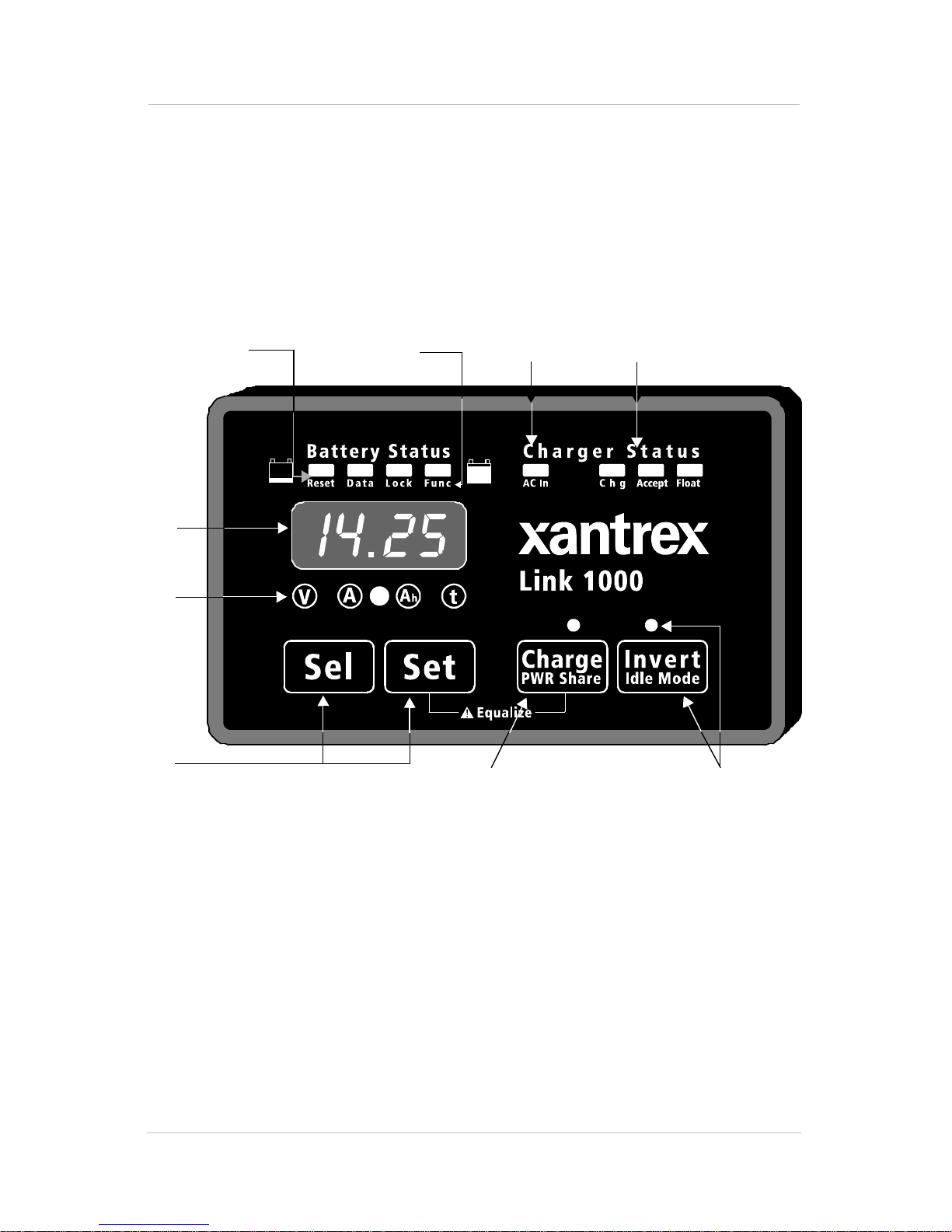
Reading the Link 1000 Control Panel
Reading the Link 1000 Control Panel
The Link 1000 control panel lets you monitor the battery
system and control the inverter/charger. Its features are
described below. Further details are provided as you need
them throughout the guide.
1
2
3
4
7
8
5
9
6
Figure 1 Link 1000 Control Panel
1
4
BATTERY STATUS light bar
When the battery system is operating, the four
LEDs in this light bar act like a “fuel gauge”. The
LEDs light in different sequences and colors to
show the battery’s present state-of-charge. The
statuses are described on page 37.
Page 13

Reading the Link 1000 Control Panel
2, 3 Numeric display and display units.
You can choose from four dis play units depen ding on the
type of information you want to see:
• Volts
•Amps
• Ah (Amp-hours)
• Time Remaining
The procedure for changing display units is given on
page 36 along with an explanation of each display unit.
Note
: The numeric display also shows Error Codes. If
an error occurs, the display alternates between the
monitoring function you have selected and the Error
Code. For details about Error Codes, see page 48.
4
SEL and SET buttons
SET lets you access Setup mode and advanced
functions. Once you are in Setup mode, you press
SEL to choose a function or a sett ing. Proc edures for
changing values are given in Chapter 3.
5 CHARGE/PWR SHARE button and LED
Lets you start a charge cycle (see page 40) or change the
Power Share mode setting (see page 27).
6
7
INVERT/IDLE MODE button and LED
Lets you activate the invert funct ion (see page 38) or
change the Idle mode setting (see page 28).
RESET, DATA, LOCK, FUNC LEDs
•
RESET: When it is on, this LED indicates that you are
resetting Ah (Amp-hours) to zero or that you are
returning all settings to the factory defaults. (See
page 21.)
•
DATA: Indicates that you are looking at historical
information about your batteries. (See “Interpreting
Battery History” on page 46.)
•
LOCK: Indicates you are choosing the setting that
prevents people from inadvertently changing your
setup values. (See page 21.)
•
FUNC: Indicates you are accessing the advanced
functions. (See “Advanced Function Values” on
page 29.)
5
Page 14

Reading the Link 1000 Control Panel
8 AC IN LED
Indicates that AC power is present.
9 CHARGER STATUS LEDs:
•
CHG (Red): When this LED is on solid, the battery is
in Bulk charge mode. When this LED is flashing, the
battery is equalizing.
•
ACCEPT (orange): The battery is in Acceptance
mode.
•
FLOAT (green): The battery is in Float mode.
Where to go From Here
• To install the Link 1000, see page 7.
• To set up the Link 1000, see page 19.
• To use the Link 1000, see page 35.
• To call for technical support, see page 56.
6
Page 15

Installing the
Link 1000
Chapter 2 gives:
• An overview of the installation process
• A list of installation tools and equipment
• Installation procedures
We recommend that you read the entire
chapter so you can plan the installation and
obtain all the materials you need before
starting the installation.
7
Page 16

Planning the Installation
Planning the Installation
Supplied Parts
❐ Link 1000 control panel and 4 mounting screws
❐ 500 amp precision shunt
❐ 25 foot RJ11 phone cable
❐ Owner’s guide
Materials You Need to Supply
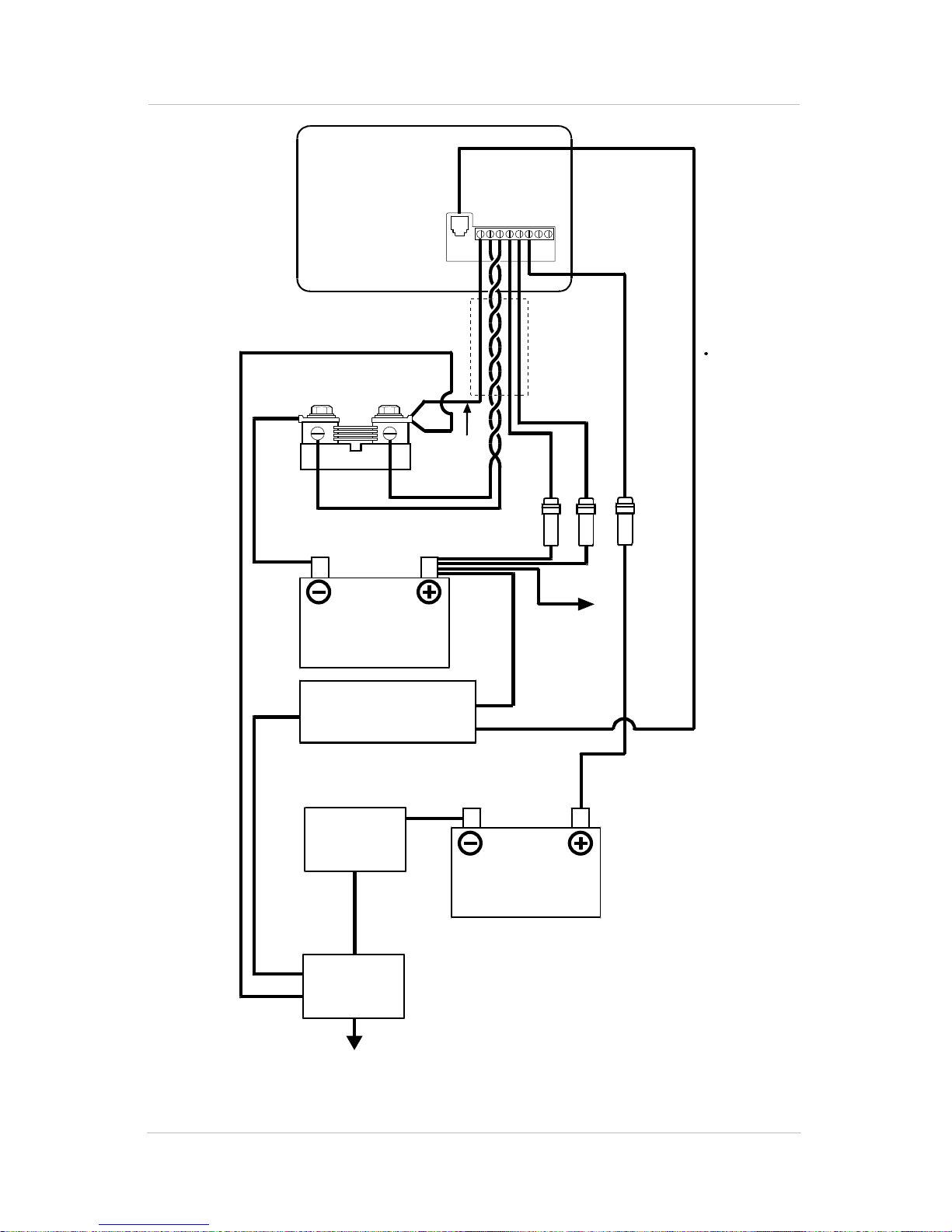
Refer to Figure 2 on page 12.
❐ Wire harness to connect the Link 1000 control panel to
the shunt and to the positive battery terminal. You can
use 18AWG, twisted pair, for this wiring. You can also
buy the harness from the dealer you bought the Link
1000 from or from West Marine.
Contact West Marine at:
• 1-800-BOATING (Canada and US)
• Fax: 1-831-761-4421 (Canada and US)
When ordering the harness, quote these part numbers:
• 84-2014-00: 25 foot (7.62m) 8-conductor twisted pair
wire
• 84-2015-00: 50 foot (15.24m) 8- conduc tor twi sted pai r
wire
❐ Appropriately sized copper cable and connectors to
connect the shunt to the battery and the negative bus for
DC loads
Consult a local cable supplier about cable size and
connector type. You may find it convenient to have the
cable supplier attach the connectors.
❐ 2, 2 amp fuses and fuse holders. (Three fuses and fuse
holders if you are monitoring a second battery.)
❐ 2 screws to mount the shunt
8
Page 17

Tools
Planning the Installation
❐ 2 strain reliefs (cabl e clamps ) for the wires and phone
cable coming out the back of the control panel
❐ Anti-corrosive sp ray
❐ High current shunt. If your starter current exceeds 500
amps for more than ten seconds, you will need a heavy
duty (1000 amp) shunt instead of the 500 amp shunt that
is supplied with the Link 1000. (You can also use a
separate engine starting battery whose negative is
connected directly to the engine.) The heavy duty shunt
part number is 84-2-13-00.
❐ Wi r e cutt er and str ipper
❐ Small slot head sc rewdriver (for the s crews on the
terminal block)
❐ Phillips screwdriver (for the control panel mounting
screws)
❐ Needle- nose pliers
❐ 9/16 in. wrench to secure cables to the shunt
Installation Considerations
Safety
• If you are using flooded lead-acid batteries, install them
in a separate battery compartment.
• Wiring should be in accordance with NEC, ABYC, or
other applicable national or regional codes.
Performance
• Do not connect anything other than the shunt to the
negative battery terminal. Connect all other loads and
sources to the load side of the shunt. (See Figure 2.)
9
Page 18

Planning the Installation
• The shunt sense leads must be 18AWG twisted pair
wires.
• Install fuses within seven inches (18cm) of the battery.
Color-Coded Wiring
To avoid confusion during installation, Xantrex recommends
that you buy wires that have the same color coding as shown
in Figure 2.
Twisted Pair Wires
If you wish, you can mak e your own twisted pai rs by twist ing
together two wires with a twist every inch. If you make your
own twisted pair, wrap tape around the wi re s every twelve or
sixteen inches (30 to 40cm) to keep the wires together and to
make them easier to pull through holes and raceways.
Separate Engine Starting Battery
In order to monitor star t bat te ry volta ge, you nee d to connect
a sense lead from th e Link 1000 terminal block to the posi tive
battery terminal of the starting battery. This procedure also
requires a 2 am p fuse and fuse holder. See step 6 on page 16
for install ation details, and see page 33 for information about
turning this function on.
10
Page 19

Installing the Link 1000
Overview of Installation Steps
Complete the installation in this order. Refer to Figure 2.
1. Mount the control panel (page 13).
2. Mount the shunt, and cable it to the negative battery
terminal. Cable the load side of the shunt to the negative
bus for DC loads (page 14).
3. Connect wire s to t he Link 1000 terminal block (page 15).
4. Connect wire s from the terminal bl ock to the shunt and to
the battery’s positive terminal (page 16).
5. Install the fuses (page 17).
6. Connect the phone cable to the control panel and the
inverter/charger (page 17).
Installing the Link 1000
11
Page 20
Installing the Link 1000
Rear of Link 1000
Control Panel
Phone
Cable
System Negative
500A
Shunt
Battery
Side
Orange
Gnd.
Stud
Battery
Load
Side
Green
Black
12345
678
Violet
Cable
Jacket
Red
Blue
2 Amp
Fuses
Pos.
Distribution
12
Inverter/Charger
Engine
Starter
Negative
Start
Battery
Neg.
Distribution
Figure 2 System Overview (Wiring)
Page 21
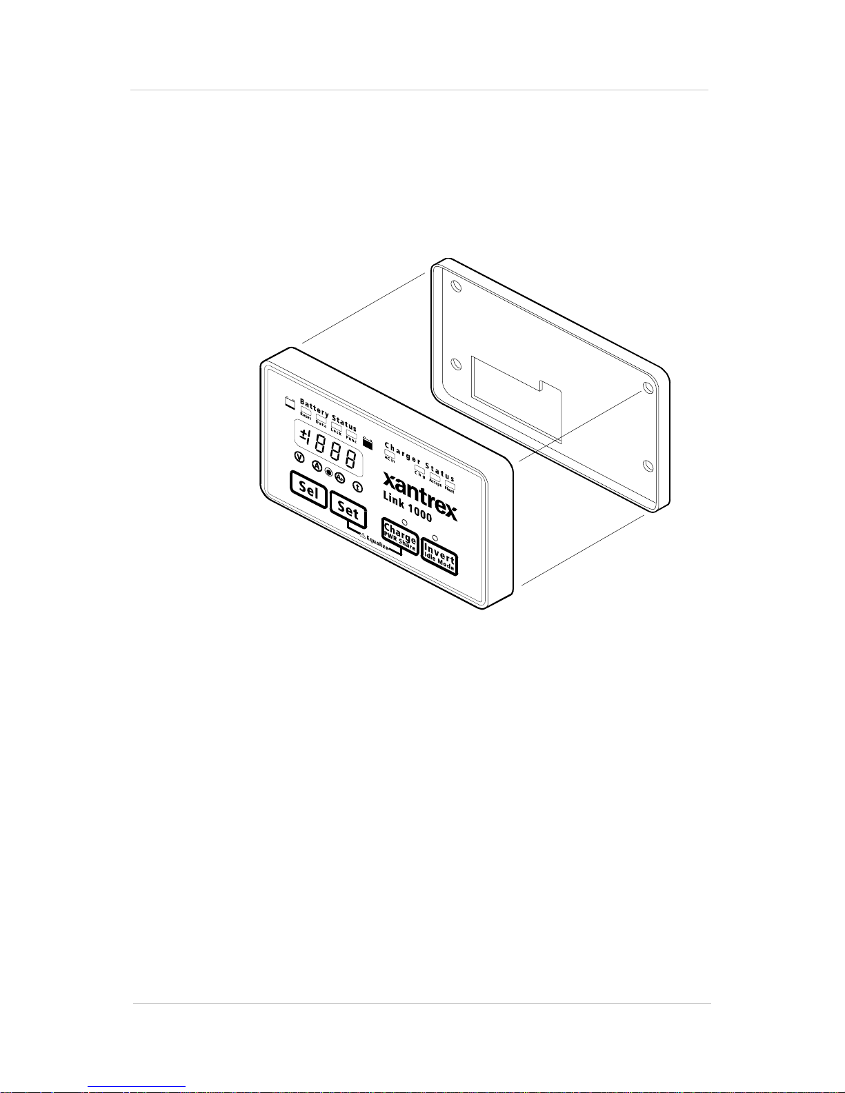
Mounting the Link 1000 Control Panel
The Link 1000 contr ol pane l cons ists o f a dis play pa nel and a
mounting plate.
To mount the control panel:
1. Separate the display panel and the mounting plate.
Installing the Link 1000
Mounting Plate
Display Panel
Figure 3 Display Panel and Mounting Plate
2. If you are going to run the phone cord and wires through
the opening in the rear of the mounting plate, make a
cutout in the mounting surface using the mounting plate
as a template. (You can also run the phone cord and wire s
down from the bottom of the mounting plate.)
3. Screw the mounting plate to the mounting surface as
shown in Figure 4.
13
Page 22
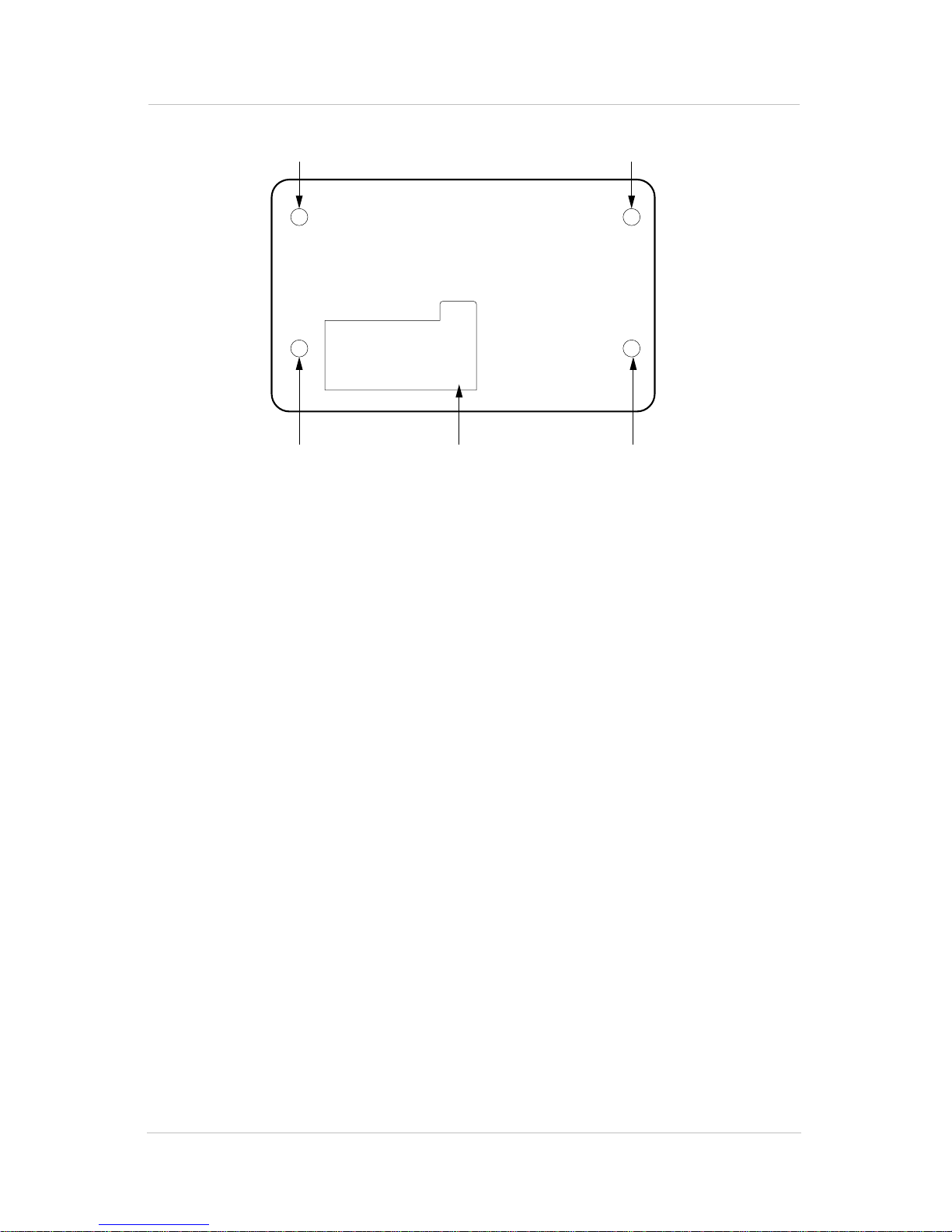
Installing the Link 1000
Countersunk
Screw
Pan Head
Screw
Figure 4 Link 1000 Mounting Plate
Cutout for Cables
and Phone Cable
Pan Head
Screw
Countersunk
Screw
Mounting and Cabling the Shunt
To mount and cable the shunt:
1. Screw the shunt to a suitable mounting surface.
2. Connect the shunt to the negative terminal of the battery
using ring terminals or locked spade terminals on a
copper cable that is sized appropriately for the current
carrying capacity of the system.
Ensure that no other wires are connected directly to the
negative battery terminal or to the negative side of the
shunt. All current must flow through the shunt.
3. Connect the load side of the shunt to the negati ve bus for
DC loads using a copper ca ble that is sized appropriately
for the current carrying capacity of the system.
If you are not using a negative bus for DC loa ds, connect
the load side of the shunt to the negative side of the
system.
14
Page 23

Wiring the Terminal Block
Prepare for wiring by following these guidelines:
• Pul l the wire s and the ph one cable t hrough the o pening in
the mounting plate (unless you are running them down
from the bottom of the mounting plate).
• Prepare the wires by giving each:
• A clean cut
•A clean strip
• A tightly twisted end
• Loosen the terminal block screws, pry the wire clamps
open with a paper clip, and insert the wires using needlenose pliers.
• Tighten the screws firmly, but do not overtighten.
Installing the Link 1000
To wire the terminal block:
• Insert the wires in the terminal block following the
sequence shown below.
Note: Terminal 1 is next to the phone cable jack.
Terminal
1Black. Control panel negative to the large bolt on the
2 Green. Sense lead to the load side of the shunt.
3Orange. Sense lead to the battery side of the shunt.
4Blue. Voltage sense lead to the positive battery
5Red. Power lead to the positive battery terminal.
6 Violet. Voltage sense lead to the positive battery
Wire Color and Function
load side of the shunt.
terminal.
terminal. Connect this lead if you are monitoring the
voltage of a second (starting) battery.
7 Not used
8 Not used
15
Page 24

Installing the Link 1000
Connecting Terminal Block Wires to Sh unt and Battery
To connect the terminal block wires:
1. Connect the black DC power wire (terminal 1) to the
large bolt on the load side of the shunt. This wire should
be on the top of the stack of large cables on the load side
of the shunt. Do not connect this wire to the small
screw terminal with the green shunt sense lead.
2. Connect th e green le ad (termin al 2) t o th e small scre w on
the load side of the shunt. This wire must be one half of
the twisted p air made up of wires 2 a nd 3. Do n ot connect
any other wires to this screw.
3. Connect the orange lead (terminal 3) to the small screw
on the battery side of the shunt. This wire must be one
half of the twisted pair made up of wires 2 and 3. Do not
connect any other wires to this screw.
4. Connect the blue voltage sense lead (terminal 4) to a 2
amp fuse holder located within 7 in. (18 cm) of the
battery. Connect the other side of the fuse holder to the
positive battery terminal. Do not install the fuse yet.
5. Connect the red power wire (terminal 5) to a 2 amp fuse
holder located within 7 in. (18 cm) of the battery.
Connect the other side of the fuse holder to the positive
battery terminal. Do not install the fuse yet.
6. If you a re going to monitor a startin g ba tt er y, connect the
violet second battery voltage sense lead (terminal 6) to a
2 amp fuse holder located within 7 in. (18 cm) of the
second (starting) battery. Connect the other side of the
fuse holder t o t he positive battery termina l o f t he st arting
battery. Do not install the fuse yet.
Note: If you are going to monitor the starting battery,
you must enable Function F11 during setup. See
page 33.
16
Page 25

Installing Fuses
To install fuses:
1. Install a 2 amp fuse in the fuse holder in the blue wire.
2. If you are using a starting battery, insert a 2 amp fuse in
the fuse holder in the violet wire.
3. Instal l a 2 amp fuse in the fu se hol der in the red wire. Th e
fuse should be connected in a smooth motion. A
“ragged” power up may cause the Link 1000 to lock up.
The
come on. The
supplied to the inverter.
Installing the Link 1000
CAUTION
Install the fuses in the sequen ce listed below to
prevent damage to the Link 1000.
BATTERY STATUS LEDs and the Numeric Display
AC IN LED comes on if AC power is being
Connecting the Phone Cable
CAUTION
Make sure you have made all DC power and shunt
connections before connecting the phone cable to
the inver t er/charger.
• Plug the phone cable into the jack on the display panel
and the jack on the inverter/charger, and then clip the
display panel into the mounting plate.
Testing the Installation
After installing the Link 1000, test its operation.
To verify that the shunt leads are connected correctly:
1. Select Amps as the display unit by pressing
Amps LED comes on.
SEL until the
2. Make a note of the Amps reading.
17
Page 26

Installing the Link 1000
3. Turn the charger off.
4. Turn on a load (for example, a light bulb).
5. Make a note of the Amps reading.
It should be less than the reading you took in step 2. If it
is not, the sh unt le ads are r evers ed (t hat i s, the green wir e
from terminal 2 and the orange wire from terminal 3 are
reversed).
Maintenance
Because the shunt senses very small currents, use an anticorrosive spr ay to keep the leads free fr om corrosi on. (Do not
spray the leads at the terminal block end.)
Disconnecting the Inverter/Charger
CAUTION
If you need to disconnect the inverter/charger,
unplug the phone cord from the inverter/charger
before you remove the DC power and shunt
connections.
18
Page 27

Setting up the
Link 1000
Chapter 3 explains:
• How to set up the Link 1000 to best suit
your battery system
• Each setting as well as the options for
each setting
• Whether you should change settings or
leave the default setting
(See “Reading the Link 1000 Control Panel”
on page 4 for locations and descriptions of
the buttons, displays, and indicators on the
Link 1000 control panel.)
19
Page 28

About Link 1000 Settings
About Link 1000 Settings
The Link 1000 is designed to operate out of the box, and
except when noted, you shouldn’t need to change the default
settings. (The default settings are listed on page 53.)
Probable Changes
You will pr obably need to chan ge the def ault settin gs for:
• Battery capacity (page 23)
• Battery type (page 23)
Possible Changes
You may need to change the default settings for:
• Ambient temperature if your inverter/charger doesn’t
have a battery temperature sensor (page 24).
•Power sharing (page 27)
Other Settings
Review this chapter completely to determine whether you
need to change any other settings in order to monitor and
control your battery system.
How to Enter Setup Mode an d Change a Value
You must be in Setup mode to change settings.
To enter Setup mode and change a value:
1. Press and hold
SET until SEL appears in the display
(about three seconds). This puts you in Setup mode.
2. Press
SEL until you reach the function you want.
3. Once you have selected the function you want, hold or
repeatedly press
4. Release
SET when the value you want appears. After five
SET to change the value.
to ten sec onds, the display retu rns to normal. This
indicates that the setting you chose is now stored in
memory.
20
Page 29

Locking Your Setup Values
After you have set up the Link 1000, you ca n lock the sett ings
to prevent anyone from inadvertently changing them.
To lock the setup:
About Link 1000 Settings
1. Hold down
2. Press
3. Press
4. If OFF appears, press
Resetting Values
You can reset Ah to zero, or you can reset all values to their
factory defaults:
• Resetting Ah to zero does not remove historical battery
data.
• Resetting all values to factory defaults (Reset All)
removes historical battery data. You usually use Reset
All when you change a battery or a battery bank.
To reset values:
1. Hold down
SET until SEL appears.
SEL until the LOCK LED comes on.
SET. The word ON or OFF appears
SET to turn the lock On.
SET until SEL appears in the display.
2. Press
SET five times until the RESET LED comes on and
AH appears.
3. At this point you can reset Ah only, or you can Reset All:
• T o reset Ah only, press
release
SET.
• To restore all factory settings, press
appears, and the n continue to hold
SET until ALL appears, and then
SET until ALL
SET for anoth er fi ve
seconds until 00.0 appears quickly and disappears.
21
Page 30

About Link 1000 Settings
Battery Capacity
The default setting is for a battery with a 200Ah capacity.
Change this setting if your battery has a different capacity.
You can test battery capacity by following the procedure on
page 42.
The most accurate way to find the capacity is to ask for the
manufacturer’s 20 hour rating.
Estimated Capacities for 12 Volt Flooded Batteri es
The values listed below are estimates for 12 V flooded
batteries except when noted.
Battery Size
U1 34–40
Group 24 80
Group 27 100
Group 30 120
Group 31 95–125
4-D 140–160
8-D 200
Golf cart & T-105
(6 volt)
L-16 (6 volt) 340–415
Estimated Ca pacities for Gel Cell Batteries
Capacity (Ah)
120–220
Gel cell batterie s usually hol d 15% fewer Ah for a give n size.
For example, a Group 27 gel cell stores about 85Ah.
Estimated Capacities for Multiple Batteries
Parallel Connection
that cons ists of two or more batteries co nnected in parallel,
multiply the Ah capacity of a single batte ry by t he number of
batteries used. For example, if three 12 volt Group 27
batteries are connected in parallel, use 300 Ah (100 Ah x 3)
for the battery capacity.
22
If you are using a single battery bank
Page 31

Series Connection If you are using a single bat tery bank t hat
consists of two or more batteries connected in series, use the
Ah capacity of one batt er y. For example, if two Troja n T-105
6 volt golf cart batteries are connected in series, use the
factory default 200 Ah for capacity.
Changing the B a ttery Capacity Setting
To change the Battery Capacity setting:
About Link 1000 Settings
1. Press
2. Press
SET until SEL appears in the display.
SEL three times. The LED comes on and 200
(the default) appears.
3. Press
Note: If you continue to hold
after four increments. If you go past your battery’s capacity,
you have to scroll to 1980Ah. The display then rolls over and
begins scrolling up from 20Ah.
Changing the B a ttery Type Setting
SET and hold it until the value you want appears.
Battery Capacity
(Ah)
20 to 40 1
40 to 100 5
more than 100 20
Incremental step
in Ah
SET, the display scrolls faster
Change the Battery Type setting if you are not using flooded
lead-acid batteries. For details about battery types, see
page 33.
To change the Battery Type setting:
1. Press and hold
2. Press
3. Press
(liquid cell), battery type 1 (gel cell, standard), battery
type 2 (gel cell, fast charge), or battery type 3 (AGM –
Absorbed Glass Mat).
SET until SEL appears.
SEL until Func F10 appears.
SET to select one of the following battery types: 0
23
Page 32

About Link 1000 Settings
Changing the Ambient Temperature Setting
When you have a battery temperature sensor:
If you have a
battery temperature sensor:
1. Leave the default Ambient Temperature setting as is.
2. Turn on Active Temperature Compensation (F16).
page 34.)
When you do not have a battery temperature sensor:
(See
If you
do not have a battery temperature sensor, and if the
temperature around the battery will be substantially different
from 70 °F (21 °C) when the batteries are being charged:
1. Turn the Active Temperature Comp ens at ion setting Off.
(See page 34.)
2. Change the Ambient Temperature setting to an
appropriate value.
Note: The Active Temperature Compensation setting mu st be
Off if you are going to change the Ambient Temperature setting.
Otherwise the Link 1000 reports the present battery temperature.
To change the Ambient Temperature setting:
1. Press and hold
2. Press
3. Press
4. Release
SEL until Func 03 appears.
SET to change the temperature in 10 °F increments.
SET when the correct temperature appears.
SET until SEL appears.
24
Page 33

Charged Parameters
There are two charged parameters: Charged Voltage and
Charged Current Percentage (%). During a charging cycle,
when the battery voltage exceeds the Charged Voltage
parameter and the charging current has dropped below the
Charged Current parameter, the battery is considered to be
fully charged. At this point the Link 1000 resets its state-ofcharge to fully charged (which appears as 0 Ah on the
display).
Changing the Charged Voltage Set tin g
About Link 1000 Settings
If your system uses 12 or 24 Volt batteries:
You don’t need
to change the default Charged Voltage setting. On power up,
the Link 1000 automatically selects an appropriate Charged
Voltage for 12 or 24 volt liquid cells and gel cells. (If you
have gel cell batteries, see “Changing the Battery Type
Setting” on page 23.)
If your system does not use 12 or 24 Volt batteries: You must
set an appropriate Charged Voltage. Use a value of 2.2 volts
per cell at normal temperatures for liquid cell batteries.
To change the Char ged Voltage setting:
1. Press and hold
2. Press
SEL once. The LED comes on and 13.2
SET until SEL appears.
appears (or 26.4 if you are using a 24 volt battery).
3. Hold down
SET until the voltage you want is displayed.
(The display mov es up i n 0.1 vol t st eps. Once t he dis play
reaches 50.0 volts, it then rolls over and starts
counting up from 8.0 volts.)
Changing the Charged Current Percentage Setting
If your system’s charging current does not fall below 2% of
battery capaci ty at the end of t he chargi ng cycle (that is, when
the battery should be full), you will need to change the
Charged Current Percentage setting. (A fully charged battery
is indicated when the green LED flashes on the
STATUS light bar.)
BATTERY
25
Page 34

About Link 1000 Settings
To change the Charged Current Percentage:
1. Press and hold
2. Press
SEL twice. The LED comes on and 002 is
SET until SEL appears.
displayed.
3. Press and hold
SET.
The display moves up in one percent steps until 7
percent is displayed. The display then rolls over and
starts counting up from 1 percent.
4. Release
Changing the Time Remaining Setting
SET when the appropriate percentage appears.
The Link 1000 has four ways of calculating the am ount of
operating time that remains. You can select:
• Pr ese nt cons umpti on level
• A four minute average
• A sixteen minute average
• A thirty-two minute average
The best sett ing depends on your type of insta llation.The f our
minute average is appropriate for most installations.
To change the Time Remaining setting:
1. Press
2. Press
SET until SEL appears.
SEL four times until the LED comes on and
001 appears.
3. Press
SET until the number you want appears. The
display moves up in 1 unit steps with choices of:
000
001
002
003
4. Release
Present consumption
4 minute average
16 minute average
32 minute average
SET when the value you want appears.
26
Page 35

Changing the Power Share Setting
Power Share is a load management feature that helps to
prevent external source AC breakers from tripping when the
charger and a number of other loads all come on at once.
Power Share automatically reduces the charger output if the
loads exceed the Power Sharing current limit.
When you plug in to an external AC power supply, set the
Power Share level to the breaker size.
If your charger trips the shore power breaker, choose a lower
Power Share setting.
To change Power Share values:
Note: The CHARGE button LED must be on before you can
change Power Share values.
About Link 1000 Settings
1. Press and hold
2. Press the
CHARGE/PWR SHARE button. The present value
appears.
3. Press and hold
through other values.
4. Release
SET when the value you want appears.
SET until SEL appears.
SET until the display begins scrolling
27
Page 36

About Link 1000 Settings
Changing the Idle Mode Setting
The Idle mode setting determines the size of AC load that is
needed to wake the inverter from its Idle (or standby) mode.
The settings ar e 0 W, 4 W, 6 W, and 15 W. The default i s 4 W.
If you set the Idle m ode to 0 W, I dle mode is actually
defeated and the inverter stays on all the time. When the
inverter is on, it draws approximately 0.5 amps. This setting
is useful if you want to ensure uninterrupted power to a very
small load like an electric clock.
The other three settings let you conserve battery power
because the inverter stays off until an adequate-sized load
brings the inverter out of Idle mode.
To change the Idle mode setting:
Note: The INVERT button LED must be on before you can
change the Idle mode setting.
1. Press and hold
2. Press the
INVERT/IDLE MODE button. The present value
SET until SEL appears.
appears.
3. Press and hold
SET until the display scrolls through the
other values.
4. Release
SET when the value you want appears.
28
Page 37

About Link 1000 Settings
Advanced Function Values
The Link 1000 has sixteen advanced functions. The default
setting is appropriate for most, and you should not change a
value unless you understand the consequence of the change.
Note: If you are monitoring more than one battery:
• Change Function F11, Second Battery Vo l tage Sense.
• Record the software revision number on page 60. (See “F15
Display Software Revision Number” on page 34.)
How to Enter Setup Mode and Change a Value: Reminder
The procedure for e ntering Setup mode and changin g a value
is given on page 20.
F01 Auto Display Scanning
Default: Off
Range: Off, On
When Auto Display Scanning is On, the display
automat ically scrolls through Volts, Amps, Ah, and Time
remaining. Each value is displayed for four seconds.
If Second Battery Voltage Sense (F11) is also on, two
voltages are shown. The flashing Volts status LED
indicates that the voltage displayed is that of the second
battery bank.
F02 Display Sleep
Default: On
Range: On, Off
This function turns off the Numeric Display and the Display
Units LEDs. All the other LEDs—
bar,
AC IN, Charger status LEDs, CHARGE LED, and INVERT
LED—stay on.
BATTERY STATUS light
29
Page 38

About Link 1000 Settings
F03 Set or Display Ambient Battery Temperatures
Default: If F16 (Active Temperature Compensation) is On,
the present battery temperature is displayed in °F. If F16 is
Off, the declared battery temperature is displayed.
Range: 30° F–120° F (–1.11° C–48.8° C) in 10° increments.
Set a different value from the default only if the battery
environment is significantly different from 70° F (21.11° C)
when the batteries are being charged by the Freedom
Inverter/Charger.
For more information abo ut battery char ging and temper ature
compensation, see “F07 Set Temperature Coefficient” on
page 31.
F04 Toggle Display Between Ah and kWhr
Default: Off
Range: Off = Ah display mode; On = kWhr display mode.
When this function is On, the Ah display is changed to a
kilowatt-hour display.
Kilowatt-hours are a very precise measurement of energy
removed from or returne d to t he batt ery bank. The Lin k 1000
uses kilowatt -hours t o determi ne whet her 100% of the e nerg y
consumed from the battery has been returned.
A recalculation of the CEF (Charge Efficiency Factor) is not
permitted unless this counter is greater than 0.00 kWhr. This
counter counts down during discharge, and the kWhrs
consumed are displayed with a negative number. While the
battery is charging, the Link 1000 counts back up with 100 %
efficiency. CEF recalculation is prevented until a positive
number is in the kWhr counter. This prevents a premature
CEF reset.
30
Page 39

F05 Turn on Alternative Energy Mode
Default: Off
Range: Off and On. On = use alternative energy defaults.
Turn Alternative Energy mode on if the Link 1000 is used in
an alternative energy system.
This function reduces the time needed to satisfy the charged
parameters from five minutes to one minute. If you are using
a semi-mechanical photovoltaic controller, we strongly
recommend that yo u also consi der changi ng Charg ed Current
to 4%. (See “Changing the Charged Current Percentage
Setting” on page 25.)
F06 Manually Set CEF
Default: Off = Auto recalculation of CEF
About Link 1000 Settings
Display: A95
Range: 65–99 in 1 number increments
This setting allows manual set up of CEF (Charging
Efficiency Factor). The default display A95 indicates the
automatic CEF recalculation feature. Returning to A95 from
a user-set CEF turns the automatic CEF feature back on. If a
user-set CEF has been selected, it will appear as a Uxx in
Data mode (where xx is the number the user has selected).
F07 Set Tempe r a ture Coeffici en t
Default: 0.5
Range: 0.1–0.5 in 0.1 step increments
We recommend that you use the default value.
This factor compensates for the impact that temperature has
on battery capacity. A typical value is 0.5% Capacity per °C.
This coefficient must be supplied by the battery
manufacturer. The default valu e is typical f or liquid l ead-acid
or gel batteries.
31
Page 40

About Link 1000 Settings
F08 Set Peukert’s Exponent
Default: 1.25 for liquid lead -acid ba tter ies. ( Bat tery Type set
to Type 0.)
The Peukert exponent refers to the “shrink rate” of your
battery bank. The more rapidly you discharge the batteries,
the more their effective size shrinks. For example, a battery
that can supply 200Ah when discharged over twenty hours
may only provide 95Ah if discharged in one hour.
When you select Battery Type (see “Changing the Battery
Type Setting” on page 23 and “F10 Select Battery Type” on
page 33), the Link 1000 automatically sets an appropriate
Peukert exponent. When the Battery Type is gel or AGM
(Type 1, 2, or 3), a default exponent of 1.11 is used.
If your battery manufacturer has given you another value,
you can enter it. Otherwise, leave the default value.
F09 Set Low Battery Discharge Floor
Default: 100%
Range: 50%–100% in 5% increments
The Link 1000 lets you set the discharge floor that it uses for
calculations. The factory-set discharge floor is 100% of Ah
capacity, corrected for high discharge rates. If you set the
discharge floor to 100%, the Time Remaining display
reports the time that remains until you have a dead battery.
We recommend that you begin charging when two yellow
battery status LEDs are on in order to conform to the “Mid
Capacity Rule” (see page 39).
Note: If you discharge below the discharge floor, and then
partially charge but remain below the discharge floor, the Time
Remaining display will continue to read zero. The Time Remaining
display will not show meaningful readings until you have recharged
above the discharge floor you have set.
32
Page 41

F10 Select Battery Type
Default: 0 (Liquid Cell)
Range: 0 = Liquid Cell ; 1 = Ge l Cell ( standard) ; 2 = Gel Cell
(fast charge); 3 = AGM (Absorbed Glass Mat)
This function sets the appropriate charge and float voltages
for the Freedom charger and sets an appropriate Peukert
exponent. Gel cell owners can use Type 1 or Type 2, but
should consult the battery manufacturer before using Type 2.
Type 3 sets Acceptance and Float voltages suited to AGM
type batteries.
F11 Turn on Second Ba tt ery Voltage Sense
Default: Off
Range: On, Off
About Link 1000 Settings
When this function is On, two voltages are displayed. When
the Volts LED is on solid, you see the voltage of the
monitored battery. If the battery Volts LED is flashing,
the second (starting) battery voltage is being displayed.
If you use this function, keep in mind that the displayed
voltage is on ly an indi cation of the battery ’ s state- of-char ge if
the battery has been at rest for at least eight hours.
A battery with an eight hour at-rest voltage of 12.4 volts or
more will probably start an engine. A battery with an eight
hour at-rest voltage of 11.1 volts will probably not start an
engine, particularly if you have dirty injectors and if the
engine doesn’t start right away.
F12 Number of Overload Conditions Experienced
Displays the number of inverte r shutdowns s ince the last h igh
level meter reset. This is primarily a troubleshooting tool.
F13 Number of Invert er Low Battery Shutdo wn s
Displays the number of inverter low battery shutdowns since
the last high level meter reset. This is p rimarily a
troubleshooti ng too l.
33
Page 42

About Link 1000 Settings
F14 Test Control Panel Display
Default: Off
Range: On while the SET button is pressed when this
function is active. Off when
This function lets you confirm that the Link 1000 control
panel display is operating properly. When you press
F14 mode:
SET is released.
SET in
•The
RESET and DATA LEDs are orange-yellow.
• All other LEDs display their normal color.
• The Numeric Display reads 188.8.
The display returns to normal when you release
Operation of the
LOCK and FUNC LEDs is conf irmed when
power is initially applied to the Link 1000.
F15 Display Software Revision Number
•Press SET to display the Software Revision Number.
This function di splays the softwar e revis ion number insta lled
in your Link 1000. Record this number on page 60 in case
you need to call Customer Service.
F16 Turn on Active Temperature Compensation
Default: Off
Range: Off, On
SET.
Turn this function On if your inverter/charger has a
temperature sensor.
Leave this function Off if you are not using a temperature
sensor.
When this function is On, the Link 1000 uses the actual
battery tempe rature re ported t o the Fr eedom Inver ter/Char ger
by a Heart TC2+2 unit, the Freedom 458 or the Freedom
Marine Inverter/Charger temperature sensor.
34
Page 43

Using the
Link 1000
Chapter 4 tells you how to:
• Read the battery’s state-of-charge
• Turn on the invert function
• Change the Idle mode setting
• Charge and equalize the batteries
• Determine battery capacity
• Activate the Power Share feature
• Synchronize the Link 1000 to the
batteries
• Read battery history
• Respond to Error Codes
35
Page 44

Monitoring Functions
Monitoring Functions
Choosing a Display Unit: Volts, Amps, Ah, or Time
By default, the numeric display shows Volts , but it can
also show Amps, Ah, and Time Remaining.
To change the display unit:
•Press
SEL until the , , or LED comes on.
The units of display are explained below.
VOLTS
A
MPS
Ah
Displays the voltage of the battery being monitored.
(The Link 1000 can also display the voltage of an
additional battery.)
Displays the flow of current into or out of the battery.
Discharging appears as a negative number. Charging
appears as a positive (unsigned) number.
For example, if 6 amps are going into the battery, the
numeric display shows 6. If 6 amps are being
consumed, the numeric display shows –6.
Displays the Ah (amp-hours) consumed.
This is the amount of energy that has been consumed
from the battery. For example, if you have operated a
10 amp load for one hour, 10 Ah have been
consumed, and the display shows –I0.
When the battery is fully charged, the Link 1000
displays 0 Ah.
T
IME
R
EMAINING
Note
: The numeric display also shows Error Codes. If an error
occurs, the display alternates between the monitoring function you
have selected and the Error Code. For details about Error Codes,
see page 48.
36
This is an estimate of the hours that the battery can
operate at its present load until it is completely
discharged. The estimate is based on a selectable,
time- averaged, rate of discharge. The default is the
average of the last four minutes of use.
While the batteries are charging, this display shows
CCC.
Page 45

Reading the Battery Stat e-of-Charge
The BATTERY STATUS light bar (see Figure 5) shows the
battery’s state-of-charge. The table explains how to read the
light bar.
BA TTERY STA TUS
Figure 5 BATTERY STATUS Light Bar
These lights Indicate this %
Monitoring Functions
3 green + 1
flashing green
4 green 80–100%
3 green 60–79%
2 yellow 40–59%
1 red 20–39%
1 flashing red 0–19%
Scaling the BATTERY STATUS Light Bar
The CEF has been recalculated.
Enough charge to start an eng ine-driv en char ging
source.
The battery is more than 80% discharged (based
on the factory sett i ngs).
You can scale the BATTERY STATUS light bar to show a
flashing red LED when your battery is more than 40%
discharg ed. To adjust the battery discharge floor, see page 32.
37
Page 46

Inverter Functions
Inverter Functions
Turning on the Invert Function
When the inverter is operating, power is taken from the
batteries and converted to AC current to power your loads.
To turn on the invert function:
•Press
The
The
INVERT LED does not indicate that the system is
INVERT.
INVERT button LED comes on.
inverting. It indicates that the inverter function is enabled.
The invert function only operates when the inverter is
connected to the battery, no external AC power is available,
and the batteries have enough power for the loads.
When the inverter is initially powered up, the invert function
is off.
Changing the Idle Mode Setting
The Idle mode setting determines the size of AC load that is
needed to wake the inverter from its Idle (or standby) mode.
To change the Idle mode setting:
•See page 28.
38
Page 47

Charging Functions
Charge your batteries when two yellow LEDs are lit on the
BATTERY STATUS light bar (if you are using the default setting
for F09: Low Battery Discharge Floor). The two yellow
LEDs indicate that 50% of battery capacity has been used.
Charging at this level is called the Mid-Capacity Rule. In
marine and RV systems, which try to mini mize char gi ng ti me
with an engine-driven alternator, or generator-powered
charging, the battery is normally charged to the 85% level.
This means that only 35% of the battery capacity is actually
available for use .
The Mid-Capacity Rule is designed to optimize battery life.
Four charging cycles are available: Bulk, Acceptance, Float,
and Equa lization. When you start a charge cycle , the charger
automatically completes a Bulk, Accept, and Float charge.
You can also start an Equalization charge manually.
Charging Functions
CHARGER STATUS LEDs are explained below, and then
The
procedures are given for charging and equalizing the
batteries.
Summary of CHARGER STATUS LEDs
This LED Indicates
AC IN (green) AC power is present.
CHG (red)
on solid
CHG (red)
flashing
ACCEPT (orange) The batteries are in Acceptance mode.
FLOAT (green) The charge is in Float mode.
The batteries are in Bulk charge mode.
An Equalization charge is being applied.
39
Page 48

Charging Functions
Charging the Ba tteries
To start a charge cycle:
•Press the
CHARGE button on, and the cycle will start
CHARGE button. (You can also leave the
automatically.)
The
CHG LED and the CHARGE button LED come on.
The charger automatically cycles through the Bulk,
Acceptance, and Float charge stages.
The charge function only operates when the inverter is
connected to a battery and external AC is available.
(On inverter/chargers that have a serial number lower than
100,000, charging is enabled when the
Equalizing the Batteries
Equalization is the controlled overcharging of a lead-acid
battery (or battery bank) to remove lead sulfate that is not
removed during normal charging. Controlled overcharging
helps the battery reach and maintain peak capacity by
equalizing the chemistry in the individual battery cells.
INVERT button is on.)
Precautions
• Equalize your batte ries ev ery thi rty days when they are in
a daily cycling service or every thirty deep cycles.
• Equalize your batteries when the battery capacity has
decreased (that is, when the batteri es do not hold loads as
well as they previously did).
WARNING: Explosion Hazard
Equalization produces explosive gases which must be
vented.
Read these precautions before you start an equalization
charge:
• Equalization causes batteries to gas. Make sure they are
well ventilated.
40
Page 49

Charging Functions
• Check the electrolyte level of all batteries before and
after equalization. Make sure the electrolyte is at the
correct level, but do not overfill because the electrolyte
may expand and overflow.
• Leave the filler ca ps screwed on loosely, or remove them
and cover the opened cell tops with a folded paper towel.
• Make sure you are present durin g equalizatio n so you can
monitor the charging cycle.
To start an equalization cycle:
CAUTION
Turn off all DC loads before you start equalization. The
voltages required during equalization can damage
sensitive equipment.
1. Make sure the charger is on and the batteries are fully
charged.
2. Press
3. Press
SET until SEL appears.
SET and CHARGE simultaneously until the CHG
LED starts flashing and 00E goes out (about five
seconds). The
CHG LED flashes throughout the
equalization cycle.
To end an equalization cycle manually:
•Press
CHARGE simultaneously.
The
SET until SEL appears, and then press SET and
CHG LED goes out and the Freedom Inverter/
Charger is forced to float when equalization ends (the
FLOAT LED comes on).
If you do not stop the equalization process manually, the
cycle ends automatically after eight hours. It also ends if
external AC power is interrupted.
To end equalization early on Freedom inverters that have a
serial number lower than 100,000, turn off both the
and
INVERT buttons.
CHARGE
41
Page 50

Charging Functions
Equalizing Gel Cell Batteries
You don’t normally equalize gel cell batteries. If they have
been severely di sc harged, however, t hi s may be the only way
to get them to begin accepting a charge. The voltage is
limited to the Acceptance charging level, but the cycle lasts
for eight hours.
Be sure that bat tery type is set to 002 be fore y ou equalize ge l
cell batteries.
Activating Power Share
Power Share is a load management feature that helps prevent
external source AC breake rs fr om tripping when the charger
and a number of o ther loads all c ome o n at on ce. Power shar e
automatically reduces the output of the Freedom Inverter/
Charger if the AC loads exceed a specified current lim it.
To change the Power Share setting:
•See page 27.
Battery Capacity Testing
To determine the actual amount of energy your batteries can
store, you conduct periodic capacity tests. A capacity test
should start wit h a ba tter y that has b een proper ly cha r ged an d
equalized.
Deep cycle battery capacity is usually stated as a 20 hour
discharge rate (a 100 Ah battery will provide 5 amps for
twenty hours). At discharge rates above 5 amps, the battery
will supply less tha n 100 Ah. For example, if you are drawing
100 amps out of the batte ry, it will last less than half an hour.
The following table shows battery capacity at various
discharge rates.
Battery Capacity at Various Discharge Rates
Hours to Discharge
20 100%
42
Capacity (as a percent of the
20 hour rate)
Page 51

Charging Functions
Battery Capacity at Various Discharge Rates
Capacity (as a percent of the
Hours to Discharge
10 89%
5 78%
3 66%
1 45%
20 hour rate)
To test battery capacity:
1. Charge the battery until the charged parameters are met.
This rese ts Ah to zero.
2. Turn on a load that draws approximately 5% of the
expected battery capacity.
3. Check the current by looking at the Amps display. The
load should be constant (for example, a light bulb).
4. Put the Link 1000 in Volts display mode.
5. When the voltage drops to 10.5 volts (or 21 volts if you
are testing a 24 volt system), turn the load off. (It should
take about twenty hours for the voltage to drop.)
6. Look at the Ah display. The number of Ah displayed
is the actual battery capacity.
If less than twenty hours passed before the voltage fell to
10.5, you can still determine the capacity by completing a
simple calculation. For example, assume that you have a 12
volt battery rated at 100 Ah. Apply a 5 amp load. If it only
took ten hours for the voltage to reach 10.5, the Link 1000
would display –50Ah. This number is the 10 hour capacity.
By dividing 50 by 89% (see the preceding table), you
determine that the actual 20 hour capacity is 56 Ah. You
could repeat th e test at 5% of the tested cap acity (2.8 am ps) to
verify the actual capacity.
43
Page 52

Charging Functions
Synchronizing the Link 1000 to the Battery
When the battery is fully charged, the Link 1000 displays 0
Ah. This indicates that no ene rgy has been removed from the
battery. (The display can also show a positive number; this
changes to 0 as soon as you place a load on the battery. See
page 45 for details about over-charge Ah).
As the battery discharges, the display shows how much
energy has been used. For example, when you run a 10 amp
load for one hour, the display shows –10 to indicate that 10
Ah have been used.
In other words, the Ah display tell s you how much ener gy has
been removed from the battery as long as the Link 1000 is
synchronized with the battery.
• If you install the Link 1000 on a fully charged battery, it
is automatically synchronized to the battery.
• If you install the Link on a battery that is partially
charged, y ou must s ynchro niz e the Link by follo wing the
procedure given here.
• Once the Link 1000 is synchronized, it stays
synchronized as the battery runs through discharge /
charge cycles. If the Link every gets out of sync with the
battery (th is ra rely happens ), you can s ynch ronize it once
again by following the procedure given here.
To synchronize the Link 1000 to the battery:
1. Discharge the battery by at least 10% of its declared
capacity.
2. Set the Ah reading to 0 by:
a) Holding down
b) Pressing
SET five tim es until the RESET LED comes
SET until SEL appears in the display.
on and AH appears.
c) Pressing
SET as soon as ALL appears.)
SET until ALL appears. (Be s ure to release
4. Char ge t he battery until the green
(For battery charging procedures, see page 40.)
Overcharge Ah are displayed as a positive number. When
the battery starts to discharge, the Link resets Ah to zero.
44
FLOAT LED comes on.
Page 53

Over-charge Ah (Accumulation of Posi tive Ah)
If the battery is 100% charged, and the Link 1000 is
synchronized with the battery, over-charge Ah are displayed
as a positive Ah number. Some accumulation of over-charge
Ah is normal with sy stems th at are con tinuously connected t o
a charge r. For example, a 100 Ah batt ery a t Floa t volt age wi ll
normally have a little less than 0.1 amps flowing into it. This
means you would expect about 2.4 Ah of over-charge to
accumulate each day. If your battery system is larger, more
current flows and more over-charge Ah accumulate.
If the charging system is a constant voltage type set at 14.2
volts, as much as 1 amp may be flowing all the time af ter the
battery has reached the charged parameters. Prolonged high
voltage applied to a fully charged battery w ill likely cause
gassing, and you would expect to see a large Ah over-charge
every day. This is a indicates that you are shortening the life
of your battery by over charging. Check your Link 1000
before turning off a charging source to see that you have not
accumulated too m any over-charge Ah. (When discharging
begins, the Link 1000 resets to zero and begins to report Ah
consumed.)
Charging Functions
If you equalize your batteries, some over-charge Ah will
accumulate. This is normal and ensures that the Link 1000
stays synchronized with the battery state-of-charge.
45
Page 54

Battery History
Battery History
The Link 1000 stores four kinds of information about the
battery.
To access battery history:
1. Hold down
2. Press
SEL until the DATA LED comes on.
SET until SEL appears.
E99 is displayed. This is the Charging Efficiency Factor
(CEF).
3. Press
SEL again.
+I999 is displayed. This is the number of CEF
Recalculations.
4. Press
SEL again.
–999 is display ed. This is the Deepest Depth o f
Discharge.
5. Press
SEL again.
i999 is displayed. This is the Average Depth of
Discharge.
Interpreting Battery History
46
E99: Charging Efficiency Factor
The Charging Efficiency
Factor (CEF) is the energy efficiency of the battery. This
indicates the health of the battery. The lower the efficiency,
the worse the health of the battery.
The Ah CEF, not the kilowatt-hour CEF, is displayed. A
display of E99 indicates a 99% CEF based on Ah. The
Default s etting is 95%.
If the CEF display has a u in fro nt of it, this means th e CEF
has been selected by the user. See page 31 for details about
changing the CEF settings.
+I999: Number of CEF Recalculations This is the number of
times the battery has been discharged more than 10% and
then completely recharged (recharged until the Charged
Page 55

Battery History
Parameters have been met) since the la st time it was reset to
the factory defaults. A discharge of less than 10% of battery
capacity is not counted as a “cycle”.
–999: Deepest Discharge This is the deepest discharge in Ah
since the last time the Link 1000 was reset to the factory
defaults.
i999: Average Discharge This is the average of al l discharges
as an Ah value si nce the la st reset to facto ry defaul ts. For bes t
battery life, you should not routinely discharge more than
50% of your batt ery’s capacity. If you do, you shorten i ts life .
An average discharge of 500Ah on a 900Ah battery is
demanding but not unreasonable. An average discharge of
180Ah from a 200Ah batte ry is excessiv e and will shorten t he
battery’s life.
47
Page 56

Read ing E rror Cod es
Reading Error Codes
When the Link 1000 detect s a problem, an err or code appea rs
in the numeric display. The display alternates between
showing the monitoring function you have selected and the
error code. The error code flashes until the error is corrected.
The following tabl e lists each Error Code, describes t he cause
of the error, and indicates the action to take, if any.
Error
Code Meaning
E01 High battery voltage shutdown
(Inverter/charger error)
Battery voltage has risen above 15.5 V for 12 V
inverter s or above 31 V for 24 V inverters.
Check all charging sources (that is, solar panels,
alternators, etc.
E02 Low battery voltage shutdown
(Inverter/charger error)
Battery voltage has dropped below 10.5 V for 12 V
inverters or below 21 V for 24 V inverters.
Check for a dead battery or poor battery connections.
E03 Over temperature shutdown
(Inverter/charger error)
The inverter has overheated and shut down. It will reset
automatically after it has cooled sufficiently.
Make sure there is adequate ventilation around the
inverter.
E04 Battery overload
(Inverter/charger error)
The battery is excessively discharged or there is a
shorted battery.
See your inverter/charger owner’s manual for
information about charging excessively discharged
batteries.
48
Page 57

Error
Code Meaning
E05 AC backfeed
(Inverter/charger error)
AC power from an outside source has been fed to the
AC output of the inverter. This could damage the
inverter.
Disconnect incoming AC power and correct the fault
immediately. Consult a qualified electrician if you do
not know how to diagnose and treat this problem.
E06 Electronic overload
(Inverter/charger error)
The inverter is connected to a load that is too large for it,
or the inverter output has shorted out.
Remove the load. Reset the inverter by cycling the
charger on and off, or connect AC power from an
outside source.
Reading Error Codes
E07 Triac control error
(Inverter/charger error)
A switch inside the charger has overheated.
Turn the charger off and let it cool. Make sure there is
adequate ventilation around the inverter.
E08 High battery voltage shutdo wn during charging
(Inverter/charger error)
Check all charging sources (solar panels, alternators,
other battery chargers, etc.) for proper voltage.
Reset the inverter by cycling the charger off and on.
E09 Spare
E010 Depowered
(Link 1000)
This code appears when the Link 1000 is first powered
up and whenever power has been interrupted or has
dipped below the operating voltage of the Link 1000.
This code can be triggered by voltage dips during engine
starting if the Link 100 0 i s powe red by the same battery
that starts the engine.
E011 Spare
49
Page 58

Read ing E rror Cod es
Error
Code Meaning
E012 Battery voltage sense lead open
E013 Spare
E014 Inappropriate charged voltage selected for the
(Link 1000)
Check the fuse or any other connections in the voltage
sense lead (blue wire) to the battery.
sensed voltage
(Link 1000)
This code appears if the Charged Voltage parameter is
above 20 V and the sensed voltage is below 20 V, or if
the sensed voltage is above 20 V and Charged Voltage
parameter is below 20 V.
This code will help you avoid an incorrect setup.
E015 Incoming AC polarity reversed
(Inverter/charger error)
Check the incoming AC wiring for reversed polarity
(positive and neutral reversed).
Consult a qualified electrician if you do not know how
to diagnose and correct this condit ion.
0L Link 1000 reading out of range
(Link 1000)
50
Page 59

Specifications
Appendix A lists:
• Electrical and physical specifications for
the Link 1000
• Default settings
Specifications are subject to change without
notice.
51
Page 60

Control Panel: Electrical Specifications
Control Panel: Electrical Specifications
DC Power supply voltage 8–40 VDC . (Not for us e with 32 vol t
systems.)
Power consumption For 12 volt systems:
• 90 mA (typical)
• 170 mA (full disp lay brightness)
• 25 mA (sleep mode; only
BATTERY STATUS LEDS on.)
Values are approximately half on 24
volt systems.
Voltage measurement range 0.1–50 VDC
Voltage resolution 0.05 VDC
Voltage accuracy ±0.10 VDC at full scale
Current measurement range ±500 Amps DC
Current resolution • 0.1 amp DC (from ±0–±42.0
amps)
• 1 amp DC (from ±42–±500
amps)
Current accuracy • ±0.1 amp DC at full scale low
range
• ±1 amp DC at full scale high
range
Current shunt ±0.25% ratio: 50mV @ 500A
Amp hour range ±1,999Ah
Time remaining range 255 hours maximum
Control Panel: Physical Specifications
Width 4.725 in. (120 mm)
Height 2.975 in. (75.5 mm)
Depth 1.075 in. (27.3 mm)
Weig ht 4.6 oz. (2 g)
Front panel finish Water resistant, splash proof
52
Page 61

Default Settings
Inverter/Charger Controls
Default Settings
CHARGE
INVERT
On
Off
Idle Mode 4 Watts (5 Watts o n Series 458 units)
Power Sharing 30 amps (Off for Freedom 25 units)
Monitoring Functions
Charged Voltage 13.2 volts for 12 volt systems
26.4 volts for 24 volt systems
Charged Current 2% (of battery capacity, 4 amps @
200 Ah)
Battery Capacity 200Ah
CEF 95% (Charge Efficiency Factor)
Ambient Temperature 70 °C
Battery Type 0 (liquid cell)
Peukert Exponent 1.25
53
Page 62

54
Page 63

Product and
System
Information
Appendix B contains:
• The warranty for your Link 1000
• Instructions for returning the product for
servicing
• A table (see page 61) where you can
record information about your system in
case you need to contact Customer
Service
55
Page 64

Warranty
Warranty
What does this warranty cover? This warranty is provide d by
Xantrex Technology Inc. (“Xantrex”) and covers defects in
workmanship and materials in your Xantrex Link 1000 Battery
Monitor. This warranty lasts for a Warranty Period of 12 months
from the date of purchase at point of sale to you, the original end
user customer.
This Limited Warranty is not transferable.
What will Xantrex do? X antrex will, at its o p tion, repair or
replace the defective product free of charge, provided that you
notify Xantrex of the product defect within the Warranty Period,
and provided that Xantrex through inspection establishes the
existence of such a defect and that it is covered by this Limited
Warranty.
Xantrex will, at its option, use new and/or reconditioned parts in
performing warranty repair and building replacement products.
Xantrex reserves the right to use parts or products of original or
improved design in the repair or replacement. If Xantrex repairs or
replaces a product, its warranty continues for the remaining portion
of the ori ginal Warranty Period or 90 days from the date of the
return shipment to the customer, whichever is greater. All replaced
products and all parts removed from repaired products become the
property of Xantr ex.
56
Xantrex covers both par ts and labor n ecessary to repair the pro duct,
and return shipment to the customer via a Xantrex-selected nonexpedited surface freight within the contiguous United States and
Canada. Alaska and H awaii are excluded. Contact Xantrex
Customer Service for details on freight policy for return shipments
outside of the contiguous United States and Canada.
How do you get service? If your product requires
troubleshooting or warranty service, contact your merchant. If you
are unable to contact your merchant, or the merchant is unable to
provide service, contact Xantrex directly at:
Phone: 1-800-670-0707 (toll-free in North America) 1-604-4222777 (direct)
Fax: 1-604-420-2145
Email: CustomerService@xantrex.com
Page 65

Warranty
Direct returns may be performed according to the Xantrex Return
Material Authorization Policy described in your product manual.
For some products, Xantrex maintains a network of regional
Authorized Service Centers. Call Xantrex or check our website to
see if your product can be repaired at one of these facilities.
In any warranty claim, dated proof of purchas e must accompany the
product and the product must not have been disassembled or
modified without prior written authorization by Xantrex.
Proof of purchase may be in any one of the following forms:
• The dated purchase receipt from the original purchase of the
product at point of sale to the end user, or
• The dated dealer invoice or purchase receipt showing original
equipment manufacturer (OEM) status, or
• The dated invoice or purchase receipt showing the product
exchanged under warrant y
What does this warranty not cover? This Limited Warranty
does not cover normal wear and tear of the product or costs related
to the removal, installation, or troubleshooting of the customer's
electrical systems. This warranty does not apply to and Xantrex will
not be responsible for any defect in or damage to:
a) the product if it has been misused, neglected, improperly
installed, physically damaged or altered, either internally or
externally, or damaged from improper use or use in an unsuitable
environment;
b) the product if it has been subjected to fire, water, generalized
corrosion, biological infestations, or input voltage that creates
operating conditions beyond the maxi mum or minimum limits
listed in the Xantrex product specifications including high input
voltage from generators and lightning strikes;
c) the product if repairs have been done to it other than by Xantrex
or its authorized service centers (hereafter "ASCs");
d) the product if it is used as a component part of a product
expressly warranted by another manufacturer;
e) the product if its original identification (trade-mark, serial
number) markings have been defaced, altered, or removed.
57
Page 66

Disclaimer
Disclaimer
Product
THIS LIMITED WARRANTY IS THE SOLE AND EXCLUSIVE
WAR RANTY PROVIDED BY XANTREX IN CONNECTION
WITH YOUR XANTREX PRODUCT AND IS, WHERE
PERMITTED BY LAW, IN LIEU OF ALL OTHER
WAR RA NTIES, CONDITIONS, GUARANTEES,
REPRESENTATIONS, OBLIGATIONS AND LIABILITIES,
EXPRESS OR IMPLIED, STATUTORY OR OTHERWISE IN
CONNECTION WITH THE PRODUCT, HOWEVER ARISING
(WHETHER BY CONTRACT, TORT, NEGLIGENCE,
PRINCIPLES OF MANUFACTURER'S LIABILITY,
OPERATION OF LAW, CONDUCT, STATEMENT OR
OTHERWISE), INCLUDING WITHOUT RESTRICTION ANY
IMPLIED WARRANTY OR CONDITION OF QUALITY,
MERCHANTABILITY OR FITNESS FOR A PARTICULAR
PURPOSE. ANY IMPLIED WARRANTY OF
MERCHANTABILITY OR FITNESS FOR A PARTICULAR
PURPOSE TO THE EXTENT REQUIRED UNDER
APPLICABLE LA W TO APPLY TO THE PRODUCT SHALL BE
LIMITED IN DURATION TO THE PERIOD STIPULATED
UNDER THIS LIMITED WARRANTY.
IN NO EVENT WILL XANTREX BE LIABLE FOR ANY
SPECIAL, DIRECT, INDIRECT, INCIDENTAL OR
CONSEQUENTIAL DAMAGES, LOSSES, COSTS OR
EXPENSES HOWEVER ARISING WHETHER IN CONTRACT
OR TORT INCLUDING WITHOUT RESTRICTION ANY
ECONOMIC LOSSES OF ANY KIND, ANY LOSS OR
DAMAGE TO PROPERTY, ANY PERSONAL INJURY, ANY
DAMAGE OR INJURY ARIS ING FROM OR AS A RESULT OF
MISUSE OR ABUSE, OR THE INCORRECT INSTALLATION,
INTEGRAT ION OR OPERATION OF THE PRODUCT.
Exclusions
If this product is a consumer product, federal law do es not allow an
exclusion of implied warranties. To the extent you are entitled to
implied warranties under federal law, to the extent permitted by
applicable law they are limited to the duration of this Limited
58
Page 67

Return Material Authorization Policy
Warranty. Some states and provinces do not allow limitations or
exclusions on implied warranties or on the duration of an implied
warranty or on the limitation or exclusion of incidental or
consequential damages, so the above limitation(s) or exclusion(s)
may not apply to you. This Limited Warranty gives you specific
legal rights. You may have other rights which may vary from state
to state or province to province.
Warning: Limitations On Use
Please refer to your product user manual for limitations on uses of
the product. Specifically, please note that the Xantrex Link 1000
Battery Monitor is not intended for use in connection with life
support systems and Xantrex makes no warranty or representation
in connection with any use of the product for such purposes.
Return Material Authorization Policy
Before returning a product directly to Xantrex you must obtain a
Return Material Authorization (RMA) number and the correct
factory "Ship To" address. Products must also be shipped prepaid.
Product shipments will be refused and returned at your expense if
they are unauthorized, returned without an RMA number clearly
marked on the outside of the shipping box, if they are shipped
collect, or if they are shipped to the wrong location.
When you contact Xantrex to obtain service, please have your
instruction manual ready for reference and be prepared to supply:
• The serial number of your product
• Information about the installation and use of the unit
• Information about the failure and/or reason for the return
• A copy of your dated proof of purchase
Record these details in “Record of System Settings” on page 61.
Return Material Procedure
If you are returning a pro duct fro m t he USA or Canada, fol low t his
procedure:
59
Page 68

Product Information
1. Package the unit safely, preferably using the original box and
packing materials. Please ensure that your product is shipped
fully insured in the original packaging or equivalent. This
warranty will not apply where the product is damaged due to
improper packaging.
2. Include the following:
• The RMA number supplied by Xantrex clearly marked on the
outside of the box
• A return address where the repaired unit can be shipped. Post
office boxes are not acceptable.
• A contact telephone number where you can be reached during
work hours.
• A brief descr iption of the problem
3. Ship the unit prepaid to the address provided by your Xantrex
Service Representative.
If you are returning a product from outside of the USA or
Canada In addition to the above, you MUST include return
freight funds and are fully responsible for all documents, duties,
tariffs, and deposits.
If you are returning a product to a Xantrex Authorized Service
Center (ASC) A Xantrex return material authorization (RMA)
number is not required. However, you must contact the ASC prior
to returning the product or presenting the unit to verify any return
procedures that may apply to that particular facility.
Product Information
Serial number
Place of purchase
Date of purchase
Software Revision
Number (F15). (See
page 34.)
60
Page 69

Record of System Settings
Setting
Battery Volts (charged) 13.2
Battery Amps (charged) 2%
Battery Capacity 200Ah
Power Share Model dependent
Idle Mode 4W
CEF
Default
Record of System Settings
Your
Setting or
Recorded
Data
Number of CEF
Recalculations
Average depth of discharge
Deepest depth of discharge
Functions
Auto Display Scanning (F01) Off
Display Sleep (F02) On
Ambient Battery
70° F (21.11° C)
Temperature (F03)
Note: F03 depends on F16.
Ah / kilowatt hours (F04) Ah
Alternate Energy Mode (F05) Of f
Manually set CEF (F06) 95%. This value
should only be set
if you don’t want
the Link 1000 to
calculate CEF
automatically.
61
Page 70

Record of System Settings
Setting
Default
Your
Setting or
Recorded
Data
Temperature Coefficient
0.5
(F07)
Peukert Exponent (F08) 1.25
Low Battery Dischar ge Floor
100%
(F09)
Battery Type (F10) 000 (liquid lead-
acid)
Second Battery Voltage
Off
Sense (F11)
Active Temperature
Off
Compensation (F16)
62
Page 71

Index
Symbols
+I999 46
Numerics
0L, Error Code 50
20 hour rating
–999
47
22, 42
A
AC IN LED 6, 39
ACCEPT LED
active temperature compensation
Ah
Ah LED described
displaying
over-charge
resetting
ambient temperature setting
Amps
Amps LED described
displaying
anti-corrosive spray
6, 39
36
36
45
21
24
36
36
9
B
batteries
20 hour rating
average discharge
charge efficiency
22, 42
47
46
34
deepest discharge
equalizing
how to charge
how to equalize
number of CEF recalculations
over charging
overload
reading the state-of-charge
table of capacities
time remaining
when to charge
battery capacity
determining
setting
testing
battery history
average discharge
charging efficiency factor (CEF)
46
deepest discharge
number of CEF recalculations
reading
BATTERY STATUS light bar
how to read
illustrated
battery temperature sensor
40
48
23
42, 43
46
37
4, 25
47
40
41
45
42
36
39, 40
22
47
47
24, 34
46
37
46
63
Page 72

Index
battery temperature sensor, effect on
settings
battery type setting
20
23, 33
C
cable clamp 9
CCC
36
CEF recalculation
CHARGE button LED
charged current percentage setting
charged parameters
CHARGER ST ATUS LEDs, described
39
Charging Efficiency Factor (CEF)
46
CHG LED
control panel
electrical specifications
illustrated
mounting
physical specifications
testing
6, 39
13
34
46
5
25
25
31,
52
4
52
E
E99 46
electrical specifications, control panel
52
equalize charge
gel cell batteries
starting
stopping manuall y
Error Codes
0L
E01
E010
E012
E014
E015
E02
E03
E04
E05
E06
E07
E08
error codes, displayed
41
50
48
49
50
50
50
48
48
48
49
49
49
49
40
42
41
36, 48
D
DATA LED 5
deepest discharge
default settings
display panel, testing
display units
changing
described
displaying
Ah
36
Amps
Time remaining
Volts
64
36
36
36
47
53
5
36
34
F
F01 Auto Display Scanning 29
F02 Display Sleep
F03 Ambient Battery Temperature
Setting
F04 Ah / kWhr Display
F05 Alternative Energy Mode
F06 Manually Set CEF
F07 Temperature Coefficient
F08 Peukert’s Exponent
F09 Low Battery Discharge Floor
F10 Battery Type
F11 Second Battery Voltage Sense
30
29
30
31
31
31
32
33
32
33
Page 73

Index
F12 Number of Overload
Conditions
F13 Number of Inverter Low Battery
Shutdowns
F14 Displa y Test
F15 Display Software Revision
Number
F16 Active Temperature
Compensation
FLOAT LED
FUNC LED
fuses
installing
type and number required
33
33
34
34
34
6, 39
5
17
8
I
–I0 36
i999
47
idle mode setting, changing
installation
diagram
materials
overview
planning
reversed leads
safety
supplied parts
testing
tools
INVERT button LED
invert function, enabling
inverter•charg er, disconnecting
12
8
11
8
18
9
8
17
9
5
28, 38
38
18
L
Link 1000
control panel illustrated
default settings
list of control functions
53
4
2
list of monitoring functions
serial number
software revision number
synchronizing to the battery
testing the display
LOCK LED
Low battery discharge floor
60
34
5
2
34
44
32
M
maintenance 18
Mid-Capacity Rule
32, 39
N
number of CEF recalculations 46
O
over-char ge Ah 45
overload, battery
48
P
phone cable
installing
removing
physical specifications, control panel
52
power consumption
power share mode
power share setting
17
18
52
42
27
R
RESET LED 5
resetting
Ah
21
all values
21
65
Page 74

Index
returning products
how to package
policy
procedure
reverse polarity
59
60
59
50
S
second battery voltage sense 33
serial number
setup values
changing
default
locking
resetting Ah
resetting all
shunt
high current
mounting and cabling
shutdown
high battery volta ge
low battery voltage
over temperature
software revision number
specifications
electrical
physical
state-of-charge, how to read
strain relief
synchron izing Link 1000 to battery
system overview diagram
60
20
53
21
21
21
9
14
48
48
48
34
52
52
37
9
12
44
displaying
36
V
values
list of default values
resetting Ah
resetting all
Vol ts, displaying
21
21
36
W
warranty
terms and conditions
wiring diagram
12
53
56
T
temperature sensor 20, 24, 34
terminal block
illustrated
wiring
time remaining
changing the setting
66
12
15
26
 Loading...