

Page 1
Xantrex
™
Heavy Duty Inverter•Charger 1012
with Ignition Protection
Installation Guide
Page 2

About Xantrex
Xantrex Technology develops, manufactures, and markets leading advanced power electronic and control products
for the Distributed, Mobile, and Programmable Power markets. The company’s enabling technology converts raw
electrical power from any central, distributed, or backup power source into high-quality power required by electronic
and electrical equipment.
Trademarks
Xantrex is a registered trademark of Xantrex International. © 2002 Xantrex International. All rights reserved.
Other trademarks, registered trademarks, and product names are the property of their respective owners and are used
herein for identification purposes only.
Notice of Copyright
Xantrex™ Heavy Duty Inverter•Charger 1012 with Ignition Protection Installation Guide © May 2002 Xantrex
International.
Disclaimer
Xantrex manufactures its products from parts and components that are new or equivalent to new, in accordance with
industry-standard practices.
UNLESS SPECIFICALLY AGREED TO IN WRITING, XANTREX TECHNOLOGY INC. (“XANTREX”):
(a) MAKES NO WARRANTY AS TO THE ACCURACY, SUFFICIENCY OR SUITABILITY OF ANY TECHNICAL OR
OTHER INFORMATION PROVIDED IN ITS MANUALS OR OTHER DOCUMENTATION.
(b) ASSUMES NO RESPONSIBILITY OR LIABILITY FOR LOSS OR DAMAGE, WHETHER DIRECT, INDIRECT,
CONSEQUENTIAL OR INCIDENTAL, WHICH MIGHT ARISE OUT OF THE USE OF SUCH INFORMATION. THE USE
OF ANY SUCH INFORMATION WILL BE ENTIRELY AT THE USER’S RISK.
Date and Revision
May 2002, Revision 1
Part number
445-0173-01-01 Rev 1
Contact information
Telephone: 1-800-670-0707 (toll free in North America)
1-604-420-1585 (outside North America)
Fax: 1-800-994-7828 (toll free in North America)
1-604-420-1591 (outside North America)
Email: CustomerService@xantrex.com
Web: www.xantrex.com
Page 3

Contents
Important Safety Instructions
Explosive Gas Precautions - - - - - - - - - - - - - - - - - - - - - - - - - - - - - - - - - - - - - - - - - - - viii
Precautions When Working With Batteries - - - - - - - - - - - - - - - - - - - - - - - - - - - - - - - - viii
FCC Information to the User - - - - - - - - - - - - - - - - - - - - - - - - - - - - - - - - - - - - - - - - - - ix
1 Installation Planning
Introduction - - - - - - - - - - - - - - - - - - - - - - - - - - - - - - - - - - - - - - - - - - - - - - - - - - - - - - - - - - 1–2
AC Components - - - - - - - - - - - - - - - - - - - - - - - - - - - - - - - - - - - - - - - - - - - - - - - - - - - - 1–3
Shorepower - - - - - - - - - - - - - - - - - - - - - - - - - - - - - - - - - - - - - - - - - - - - - - - - - - - - - 1–3
Disconnect and Over-Current Protection Device - - - - - - - - - - - - - - - - - - - - - - - - - - - - 1–3
Distribution panels - - - - - - - - - - - - - - - - - - - - - - - - - - - - - - - - - - - - - - - - - - - - - - - -1–4
AC wiring - - - - - - - - - - - - - - - - - - - - - - - - - - - - - - - - - - - - - - - - - - - - - - - - - - - - - - 1–5
AC Output Neutral Bonding - - - - - - - - - - - - - - - - - - - - - - - - - - - - - - - - - - - - - - - - - - 1–5
DC Components - - - - - - - - - - - - - - - - - - - - - - - - - - - - - - - - - - - - - - - - - - - - - - - - - - - - 1–6
DC Cabling - - - - - - - - - - - - - - - - - - - - - - - - - - - - - - - - - - - - - - - - - - - - - - - - - - - - - 1–6
DC Disconnects and Over-Current Devices - - - - - - - - - - - - - - - - - - - - - - - - - - - - - - - -1–7
Batteries - - - - - - - - - - - - - - - - - - - - - - - - - - - - - - - - - - - - - - - - - - - - - - - - - - - - - - - 1–7
Locating the Inverter•Charger - - - - - - - - - - - - - - - - - - - - - - - - - - - - - - - - - - - - - - - - - - - - - - 1–7
2 Installing the IP1012
About the Installation - - - - - - - - - - - - - - - - - - - - - - - - - - - - - - - - - - - - - - - - - - - - - - - - - - - 2–2
Materials List - - - - - - - - - - - - - - - - - - - - - - - - - - - - - - - - - - - - - - - - - - - - - - - - - - - - - - 2–2
Tools and Materials - - - - - - - - - - - - - - - - - - - - - - - - - - - - - - - - - - - - - - - - - - - - - - - - - - 2–2
Installing the IP1012 - - - - - - - - - - - - - - - - - - - - - - - - - - - - - - - - - - - - - - - - - - - - - - - - - - - - 2–3
Overview - - - - - - - - - - - - - - - - - - - - - - - - - - - - - - - - - - - - - - - - - - - - - - - - - - - - - - - - - 2–3
Mounting the Inverter•Charger - - - - - - - - - - - - - - - - - - - - - - - - - - - - - - - - - - - - - - - - - - 2–3
Connecting the AC Input Flexible Cord - - - - - - - - - - - - - - - - - - - - - - - - - - - - - - - - - - - - 2–5
Wiring considerations - - - - - - - - - - - - - - - - - - - - - - - - - - - - - - - - - - - - - - - - - - - - - -2–5
AC Input Connections - - - - - - - - - - - - - - - - - - - - - - - - - - - - - - - - - - - - - - - - - - - - - -2–5
Connecting the AC Output Flexible Cord - - - - - - - - - - - - - - - - - - - - - - - - - - - - - - - - - - - 2–7
Connecting the DC Cables - - - - - - - - - - - - - - - - - - - - - - - - - - - - - - - - - - - - - - - - - - - - - 2–7
DC Grounding - - - - - - - - - - - - - - - - - - - - - - - - - - - - - - - - - - - - - - - - - - - - - - - - - - - - 2–10
Connecting the Battery Temperature Sensor - - - - - - - - - - - - - - - - - - - - - - - - - - - - - - - - 2–11
Mounting Options - - - - - - - - - - - - - - - - - - - - - - - - - - - - - - - - - - - - - - - - - - - - - - - - 2–11
Mounting to the Negative Battery Terminal - - - - - - - - - - - - - - - - - - - - - - - - - - - - - - - 2–12
Mounting to the Side of the Battery Case - - - - - - - - - - - - - - - - - - - - - - - - - - - - - - - - 2–13
Mounting the Remote Switch - - - - - - - - - - - - - - - - - - - - - - - - - - - - - - - - - - - - - - - - - - 2–14
Page 4

Contents
Starting the Inverter•Charger- - - - - - - - - - - - - - - - - - - - - - - - - - - - - - - - - - - - - - - - - - - - - - 2–16
Testing the Installation- - - - - - - - - - - - - - - - - - - - - - - - - - - - - - - - - - - - - - - - - - - - - - - - - - 2–16
3 Battery Types and Sizes
Battery Types - - - - - - - - - - - - - - - - - - - - - - - - - - - - - - - - - - - - - - - - - - - - - - - - - - - - - - - - - 3–1
Automotive Starting Batteries - - - - - - - - - - - - - - - - - - - - - - - - - - - - - - - - - - - - - - - - - - - 3–1
Deep-Cycle Lead-Acid Batteries - - - - - - - - - - - - - - - - - - - - - - - - - - - - - - - - - - - - - - - - - 3–2
Battery Size - - - - - - - - - - - - - - - - - - - - - - - - - - - - - - - - - - - - - - - - - - - - - - - - - - - - - - - - - - 3–2
Estimating Battery Requirements- - - - - - - - - - - - - - - - - - - - - - - - - - - - - - - - - - - - - - - - - - - - 3–3
Battery Sizing Example - - - - - - - - - - - - - - - - - - - - - - - - - - - - - - - - - - - - - - - - - - - - - - - 3–3
Battery Sizing Worksheet - - - - - - - - - - - - - - - - - - - - - - - - - - - - - - - - - - - - - - - - - - - - - - 3–5
Using Multiple Batteries - - - - - - - - - - - - - - - - - - - - - - - - - - - - - - - - - - - - - - - - - - - - - - - - - 3–5
Two Batteries Connected In Parallel- - - - - - - - - - - - - - - - - - - - - - - - - - - - - - - - - - - - - - - 3–5
Two Separate Battery Banks - - - - - - - - - - - - - - - - - - - - - - - - - - - - - - - - - - - - - - - - - - - - 3–6
Battery Tips - - - - - - - - - - - - - - - - - - - - - - - - - - - - - - - - - - - - - - - - - - - - - - - - - - - - - - - - - - 3–7
Index - - - - - - - - - - - - - - - - - - - - - - - - - - - - - - - - - - - - - - - - - - - - - - - - - - - - Index–1
iv
Page 5

Figures
Figure 1-1 Typical IP1012 installation- - - - - - - - - - - - - - - - - - - - - - - - - - - - - - - - - - - - - - - - - - - -1–2
Figure 2-1 Mounting holes on base - - - - - - - - - - - - - - - - - - - - - - - - - - - - - - - - - - - - - - - - - - - - - - 2–4
Figure 2-2 Mounting the IP1012- - - - - - - - - - - - - - - - - - - - - - - - - - - - - - - - - - - - - - - - - - - - - - - - 2–4
Figure 2-3 Bracket mounting option - - - - - - - - - - - - - - - - - - - - - - - - - - - - - - - - - - - - - - - - - - - - -2–5
Figure 2-4 AC input terminal - - - - - - - - - - - - - - - - - - - - - - - - - - - - - - - - - - - - - - - - - - - - - - - - - - 2–6
Figure 2-5 Making the AC input connection - - - - - - - - - - - - - - - - - - - - - - - - - - - - - - - - - - - - - - - - 2–6
Figure 2-6 Connection order for DC cables - - - - - - - - - - - - - - - - - - - - - - - - - - - - - - - - - - - - - - - - 2–8
Figure 2-7 Connection at DC terminal of the IP1012 - - - - - - - - - - - - - - - - - - - - - - - - - - - - - - - - - - 2–9
Figure 2-8 Connection at the battery - - - - - - - - - - - - - - - - - - - - - - - - - - - - - - - - - - - - - - - - - - - - 2–10
Figure 2-9 DC Grounding - - - - - - - - - - - - - - - - - - - - - - - - - - - - - - - - - - - - - - - - - - - - - - - - - - - 2–11
Figure 2-10 BTS on Negative Battery Terminal - - - - - - - - - - - - - - - - - - - - - - - - - - - - - - - - - - - - 2–13
Figure 2-11 BTS Attached to Battery Case- - - - - - - - - - - - - - - - - - - - - - - - - - - - - - - - - - - - - - - - 2–14
Figure 2-12 Connecting the battery temperature sensor - - - - - - - - - - - - - - - - - - - - - - - - - - - - - - - 2–14
Figure 2-13 Remote switch dimensions - - - - - - - - - - - - - - - - - - - - - - - - - - - - - - - - - - - - - - - - - - 2–15
Figure 2-14 Final mounting of the remote switch - - - - - - - - - - - - - - - - - - - - - - - - - - - - - - - - - - - 2–16
Figure 3-1 Configuration for Normal Loads - - - - - - - - - - - - - - - - - - - - - - - - - - - - - - - - - - - - - - - 3–6
Figure 3-2 Configuration for Heavy Loads- - - - - - - - - - - - - - - - - - - - - - - - - - - - - - - - - - - - - - - - - 3–7
445-0173-01-01 Rev 1 v
Page 6

vi 45-0173-01-01 Rev 1
Page 7

Important Safety Instructions
WARNING
This section contains important safety and operating
instructions as prescribed by UL and CSA standards for
inverter•chargers used in residential, RV, and other
applications. Read and keep this Installation Guide for future
reference.
1. Before using the inverter•charger, read all instructions and cautionary
markings on the charger, the batteries, and all appropriate sections of this
guide.
2. While this unit is sealed, Xantrex does not recommend that it be
continuously exposed to rain, snow, spray, or bilge water. Do not install the
charger in a zero-clearance or small-clearance compartment. It may reduce
the usable power range.
3. Use only attachments recommended or sold by the manufacturer. Doing
otherwise may result in a risk of fire, electric shock, or injury to persons.
4. The inverter•charger is designed to be permanently connected to your AC
and DC electrical systems. Xantrex recommends that all wiring be done by
a certified technician or electrician to ensure adherence to the local and
national electrical codes applicable in your application.
5. To avoid a risk of fire and electric shock, make sure that existing wiring is
in good condition and that wire is not undersized. Do not operate the
inverter•charger with damaged or substandard wiring.
6. Do not operate the inverter•charger if it has received a sharp blow, been
dropped, or otherwise damaged in any way. If the unit is damaged, see the
Warranty section in Appendix B, “Product and System Information” in the
Operation Guide.
vii
Page 8

Important Safety Instructions
7. Do not disassemble the inverter•charger. See Appendix D, “Product
and System Information” in the Operation Guide for instructions on
obtaining service. Attempting to service the unit yourself may result
in a risk of electrical shock or fire. Internal capacitors remain charged
after all power is disconnected.
8. To reduce the risk of electrical shock, disconnect both AC and DC
power from the inverter•charger before attempting any maintenance
or cleaning or working on any circuits connected to the unit. Turning
off controls will not reduce this risk.
9. The inverter•charger must be provided with an equipment-grounding
conductor connected to the AC input ground.
Explosive Gas Precautions
1. Working in the vicinity of lead-acid batteries is dangerous. Batteries
generate explosive gases during normal operation. Therefore you
must read this guide and follow the instructions exactly before
installing or using your inverter•charger.
2. The IP1012 has been approved as Ignition Protected. It may be
installed in areas containing gasoline tanks and fittings which require
Ignition Protected equipment. Xantrex recommends, nevertheless,
that it is safest not to install electrical equipment in these areas.
3. To reduce the risk of battery explosion, follow these instructions and
those published by the battery manufacturer and the manufacturer of
the equipment in which the battery is installed.
Precautions When Working With Batteries
1. Have someone within range of your voice or close enough to come to
your aid when you work near a lead-acid battery.
2. Have plenty of fresh water and soap nearby in case battery acid
contacts skin, clothing, or eyes.
3. Wear complete eye protection and clothing protection. Avoid
touching your eyes while working near batteries.
4. If battery acid contacts skin or clothing, wash immediately with soap
and water. If acid enters your eye, immediately flood it with running
cold water for at least twenty minutes and get medical attention
immediately.
viii 445-0173-01-01 Rev 1
Page 9

FCC Information to the User
This equipment has been tested and found to comply with the limits for a
Class B digital device, pursuant to part 15 of the FCC Rules. These limits
are designed to provide reasonable protection against harmful
interference when the equipment is operated in a residential environment.
This equipment generates, uses and can radiate radio frequency energy
and, if not installed and used in accordance with the instruction guide,
may cause harmful interference to radio communications. However, there
is no guarantee that interference will not occur in a particular installation.
If this equipment does cause harmful interference to radio or television
reception, which can be determined by turning equipment off and on, the
user is encouraged to try to correct the interference by one or more of the
following measures:
• Reorient or relocate the receiving antenna.
• Increase the separation between the equipment and the receiver.
• Connect the equipment into an outlet on a circuit different from that
to which the receiver is connected.
• Consult the dealer or an experienced radio/TV technician for help.
Important Safety Instructions
445-0173-01-01 Rev 1 ix
Page 10

x 445-0173-01-01 Rev 1
Page 11

1
Installation Planning
Chapter 1 provides information to help you plan for a
suitable installation for the IP1012. The chapter provides a
system diagram showing the components of an installation,
and provides information about each component. It also
discusses other installation considerations such as neutral to
ground bonding and the physical location of the unit.
Page 12
Installation Planning
Introduction
All types of inverter•charger installations, residential or mobile, share
common components. This chapter describes each component.
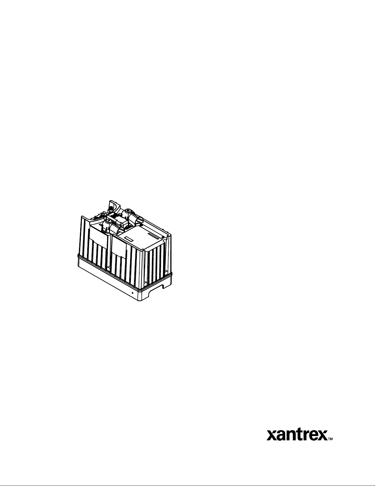
The system shown in Figure 1-1 is a basic installation. If your
requirements are more complex than this, Xantrex recommends that you
consult a qualified installer or electrician.
DC Input/Output
AC Input
AC Output
JUNCTION
BOX
Main AC Panel
Shorepower
JUNCTION
BOX
Chassis ground
AC Subpanel with
GFCI
AC Loads
Generator
DC fuse or
circuit breaker
Vehicle start
battery
12 Volt
deep cycle battery
Battery
isolator
Chassis ground
Figure 1-1 Typical IP1012 installation
1–2 445-0173-01-01 Rev 1
Page 13
AC Components
Shorepower
A source of 120 volt, 60 Hz alternating current
JUNCTION
JUNCTION
BOX
BOX
Note: Throughout this manual, the term “shorepower” refers to AC input
power from a utility grid, high-quality generator, or other source.
Disconnect and Over-Current Protection Device
To meet UL 458, and electrical code requirements, the inverter•charger
AC inputs and outputs must be provided with over-current protection
(such as a circuit breaker or fuse) and a disconnect device on both the AC
input and output:
is needed to provide energy for charging
batteries and to pass through to AC loads. This
source could be the utility grid (power
company) or an AC generator. Multiple sources
of good-quality shorepower can be used
Introduction
AC Input The circuit breaker or fuse used to
JUNCTION
JUNCTION
BOX
BOX
protect the
IP1012 Inverter•Charger must be
rated no more than 15 amps and must be
approved for use on 120 VAC branch circuits.
This circuit breaker or fuse is often in the
shorepower source. If the shorepower rating is
more than 15 amps, you need to add an
additional 15 amp breaker or fuse at the
junction box or electrical panel to which the IP1012 AC input is wired.
The wire used between the breaker and the inverter•charger input must be
sized to match the circuit breaker, in accordance with the electrical codes
or regulations applicable to your installation.
AC Output The circuit breaker or fuse
must be rated at no more than 15 amps and must
JUNCTION
JUNCTION
BOX
BOX
be approved for use on 120 VAC branch
circuits. The wire used between the
inverter•charger and the AC output breaker
must be sized to match the AC output circuit
breaker’s rating (#14 AWG or larger). The wire
from the AC output breaker to your loads must
be matched to the rating of the AC output
breakers.
445-0173-01-01 Rev 1 1–3
Page 14
Installation Planning
GFCI requirements Installations in recreational vehicles may require
GFCI protection of branch circuits connected to the AC output of the
inverter•charger. In addition, electrical codes require GFCI protection of
certain receptacles in residential installations.
Tes te d G F CI s Compliance with UL standards requires that Xantrex
test and recommend specific GFCIs. Xantrex has tested the GFCIprotected 15 amp receptacles listed in Table 1-1 and found that they
function properly when connected to the AC output of the
Table 1-1 Tested GFCI Models
Manufacturer Model number
Pass &Seymour / Legrand 1591-WCN
Leviton 6598W
Bryant GFR82FTI
Hubbell GF5252GYA
Yatai Switch YT15-G
IP1012.
Disconnect Devices: Each system requires a method of disconnecting
the AC circuits. If the over-current protection device is a circuit breaker, it
will also serve as the disconnect. If fuses are used, separate AC
disconnect switches are needed ahead of the fuses.
Distribution panels
Most systems incorporate distribution centers
both ahead of the inverter•charger and between
JUNCTION
JUNCTION
BOX
BOX
the inverter•charger and the loads (the AC load
panel). A source panel includes a main circuit
breaker, which serves as over-current protection
and as a disconnect for the AC shorepower
supply line. Additional circuit breakers serve
individual circuits, one of which serves the
inverter•charger. The AC load panel can
incorporate both the main 15 amp breaker or
fuse with disconnect if the AC output cable is directly wired into the
panel.
Note: The IP1012 is designed to be connected only to single phase
wiring circuits (line, neutral, and ground)
1–4 445-0173-01-01 Rev 1
Page 15

Introduction
AC wiring
Definition AC wiring includes all the wires and connectors
between the AC source and the inverter•charger
JUNCTION
JUNCTION
BOX
BOX
and all wiring between the inverter•charger and
the AC panels, circuit breakers, and loads.
Size and type The type and size of the wiring varies with the installation and load. For
marine and some RV applications, flexible multiple-strand wire is
required. For residential installations, solid armored cable is often used.
Local installation codes may specify solid or stranded, overall size of the
conductors, and type and temperature rating of the insulation around the
wire. Xantrex recommends stranded wire for high-vibration
environments.
Size and AC
breaker rating
AC wiring must be sized to match the current rating of the AC breakers
you provide on the input and output AC circuits in accordance with the
electrical codes or regulations applicable to your installation. Xantrex
recommends a breaker size of 15 amps, and minimum wire size of
14 AWG.
Other codes and regulations may be applicable to your installation.
AC Output Neutral Bonding
Bonding system The IP1012 provides an non-defeatable system that automatically
connects the neutral conductor of the inverter AC output circuit to safety
ground (“bonding” it) during inverter operation, and disconnects it (“unbonding” it) when the inverter•charger is connected to AC shorepower.
This system is designed to conform to installation codes that require
single-phase AC sources such as inverters and generators to have their
neutral conductors tied to ground in the same way that the neutral
conductor from the utility is tied to ground.
Transfer relay These same codes specify that the neutral can only be connected to
ground in one place at any one time. Any AC source feeding the IP1012 is
required to have its neutral already connected to ground. Therefore, to
keep from connecting the neutral to ground in a second place, the transfer
relay breaks its own neutral ground connection when connected to
shorepower.
445-0173-01-01 Rev 1 1–5
Page 16

Installation Planning
Suitability This automatic neutral-to-ground bonding system is suited for
installations in which the AC shorepower source is known to have a
bonded neutral. This will be the case in most situations: in a utility feed
after the AC source panel, at a shorepower hook-up, or a generator with a
bonded neutral.
Neutral conductor The neutral conductor of the inverter•charger’s AC output circuit is
automatically connected to the chassis ground during inverter operation.
When AC utility power is present and the inverter•charger is in charge
mode, this connection is not present, so that the utility neutral is only
connected to ground at your source panel. This conforms to National
Electrical Code requirements that separately derived AC sources (such as
inverters and generators) have their neutral conductors tied to ground in
the same way that the neutral conductor from the utility is tied to ground
at the AC source panel.
DC Components
DC Cabling
DC cabling includes all the cables and
connectors between the batteries, the DC
JUNCTION
JUNCTION
BOX
BOX
number indicates a larger cable. Wire size is usually marked on the cables
for sizes this large.
disconnect and over-current protection device,
and the inverter•charger. All installations
require multi-strand insulated cables as well as
disconnect and over-current devices. DC cable
sizes are indicated by AWG notation or MCM
notation. Under the AWG standard, a larger
gauge number indicates a smaller wire
diameter. Under the MCM standard, a larger
Xantrex offers a DC cable kit (808-0795) containing two six-foot lengths
of DC cables designed for the IP1012. If you require cables of a different
length see Table 1-2 for minimum DC cable size and maximum fuse size
for the IP1012. The DC cables must be copper and must be rated
75 °C minimum. For some applications you may require higher
temperature wires.
Table 1-2 Required DC Cable and Fuse Size
DC Cable Length Cable Size Fuse Amps
Less than 6 feet 2/0 AWG or larger 300A class T
Between 6 and 10 feet 4/0 AWG or larger 300A class T
1–6 445-0173-01-01 Rev 1
Page 17

DC Disconnects and Over-Current Devices
The DC circuit from the battery to the inverter•charger
must be equipped with a disconnect and over-current
JUNCTION
JUNCTION
BOX
BOX
device. This usually consists of a circuit breaker, a
“fused-disconnect,” or a separate fuse and DC
disconnect. Do not confuse AC circuit breakers with
DC circuit breakers. They are not interchangeable.
The rating of the fuse or breaker must be matched to
the size of cables used in accordance with the
applicable installation codes. The breaker or
disconnect and fuse should be located as close as
possible to the battery, in the positive cable. Applicable codes may limit how far
the protection can be from the battery.
Batteries
Every IP1012 system requires a 12 volt, flooded lead-acid deep-cycle battery or
group of batteries to provide the DC current that the inverter•charger converts to
AC.
Chapter 3 provides more information about battery configurations for normal
and heavy loads.
Locating the Inverter•Charger
Note: The IP1012 does not charge GEL or AGM batteries. It only uses
12-volt flooded, lead-acid battery banks.
Locating the Inverter•Charger
The inverter•charger should only be installed in locations meeting the following
requirements:
Sheltered While the unit is sealed, Xantrex does not recommend
that fluids or water should be allowed to continuously
drip or splash on the unit.
Cool Normal air temperature should be between 32°F and
77°F (0°C and 40°C)—the cooler the better.
Ventilated Allow at least 4 inches (10 cm) of clearance all around
the unit. The more clearance for ventilation around the
unit, the better the performance.
445-0173-01-01 Rev 1 1–7
Page 18

Installation Planning
Safe The unit is ignition protected and can be stored in the
same area containing gasoline tanks and fittings which
require ignition protected equipment. Xantrex
recommends, nevertheless, it is safest not to install
electrical equipment in these areas, if possible.
Close to batteries Avoid excessive cable lengths (which reduce input and
output power due to wire resistance). Use the
recommended cable lengths and sizes.
Protected from
battery acid and
gases
Close to AC
junction box
Never allow battery acid to drip on the
inverter•charger or its wiring when reading specific
gravity or filling the battery. Also, do not mount the
unit where it will be exposed to gases produced by the
batteries. These gases are very corrosive, and
prolonged exposure will damage the inverter•charger.
Avoid excessive cable lengths and use the
recommended wire length and sizes. Undersized or
unnecessarily long cables may affect charging
accuracy.
1–8 445-0173-01-01 Rev 1
Page 19

2
Chapter 2 lists the tools and materials you need to install the IP1012.
The chapter also suggests methods for mounting the unit, and provides
procedures to install and test the system.
Important: The installer is responsible for meeting all electric
codes for installing an inverter•charger.
Installing the IP1012
Page 20

Installing the IP1012
About the Installation
Before beginning your installation:
• Read the entire chapter before you begin the installation.
• Assemble all tools and materials you require for the installation.
• Review all the safety instructions on page vii.
Materials List
Contents The following materials should be in the shipping box:
❐ Inverter•Charger
❐ Battery terminal covers (1 red, 1 black)
❐ Ground lug (with mounting screw and washer)
❐ Remote switch (with mounting screws)
❐ Battery temperature sensor
❐ AC input and output cables
❐ Battery terminal nuts, lock washers and flat washer
❐ M8x20 mounting bolts, washers, and lock washers
❐ Installation Guide
❐ Operation Guide
Optional You may purchase an optional DC Cable Kit (808-0795) or a DC Cable
and Mounting kit (808-0796) from Xantrex.
Recording
information
After unpacking the unit and checking the material list, record the serial
number of the IP1012 and other purchase information in Appendix B of
the Operation Guide. If you need to call Xantrex Customer Service, you
will be asked for this information.
Tools and Materials
You need the following tools and materials to install the inverter•charger,
remote switch, and battery temperature sensor:
❐ Wire stripper
❐ #2 Phillips screwdriver
❐ Needle-nose pliers
❐ 1 slot screwdriver
❐ Wrench for DC terminals (
2–2 445-0173-01-01 Rev 1
9/16 inch or 14 mm or adjustable)
Page 21

❐ Wire connectors or crimp connectors for AC wire and appropriate
tools
❐ Two strain-relief clamps for AC cables
❐ DC battery or welding cables, 2 x6 feet of 2/0 or 2 x 10 feet of 4/0 if
you have not purchased the optional kit.
❐ 4 x 2/0 or 4 x 4/0 lugs if you have not purchased the DC cable kit
OR
❐ 6 x 2/0 or 6 x 4/0 lugs for using a fused disconnect
❐ Crimping tools, if necessary
❐ AC and DC disconnects and over-current protective devices
❐ AC output GFCI
❐ Copper wire for grounding
Installing the IP1012
Overview
Installing the IP1012
There are six main steps in the installation of the IP1012:
1. Mounting the inverter•charger
2. Connecting the AC input flexible cord
3. Connecting the AC output flexible cord
4. Grounding the DC ground
5. Connecting the battery temperature sensor.
6. Mounting and connecting the remote switch
Mounting the Inverter•Charger
Requirements To meet regulatory requirements the IP1012 must be mounted securely so
that the bottom surface is horizontal. You can meet this requirement by
securing the unit to a platform or custom bracket from the underside of
the unit. Then the platform or bracket must be firmly secured to the floor
or wall.
Optional Xantrex offers a bracket designed specifically for the IP1012, part number
808-0272. You may contact Customer Service for details. The bracket is
shown in Figure 2-3.
Floor mounting Figure 2-1 shows the position and distance between the mounting holes
on the base of the unit.
445-0173-01-01 Rev 1 2–3
Page 22

Installing the IP1012
152 mm (6”)
Figure 2-1 Mounting holes on base
To floor mount the IP1012:
1. Place the unit on a flat mounting surface with the holes drilled
according to Figure 2-1.
2. Mount each corner as shown in Figure 2-2.
3. Torque bolts to 5.6 to 6.2 ft-lbs.
4. Secure the mounting surface to the floor.
Inverter•charger
Mounting surface
Flat washer
Lock washer
M8 bolt
Figure 2-2 Mounting the IP1012
2–4 445-0173-01-01 Rev 1
Page 23

Installing the IP1012
Bracket mounting You may also mount the IP1012 in a custom bracket, then secure it to the
floor or wall. Figure 2-3 shows the Xantrex mounting bracket.
Figure 2-3 Bracket mounting option
Connecting the AC Input Flexible Cord
WARNING: Fire, Shock, and Energy Hazards
Make sure wiring is disconnected from all electrical sources
before handling. All wiring must be done in accordance with
local and national electrical wiring codes. Do not connect the
output terminals of the inverter•charger to any incoming AC
source.
Wiring considerations
Connectors Connect AC wires to shorepower with twist-on wire connectors or crimp-
on splice connectors according to the type of installation:
• For installations subject to vibration, use crimp-on connectors.
• For installations in locations not subject to vibration, twist-on wire
connectors may be used instead of crimp-on connectors.
Stripping insulation The amount of insulation you strip off individual wires will be specified
by the connector manufacturer and is different for different types of
connectors.
AC Input Connections
To make the AC input connections:
1. Strip about two inches off the jacket from the AC cord (15 ft/4.5 m)
with the female connector and separate the three wires.Strip
insulation from each of the wires according to the guidelines given by
the connector manufacturer.
2. Feed the wire into a junction box, electrical panel or other source.
445-0173-01-01 Rev 1 2–5
Page 24

Installing the IP1012
1
3. Secure with a strain relief clamp.
4. Connect wires as follows:
• the IP1012 green wire to the shorepower green or bare copper ground
wire to the appropriate ground screw inside the junction box or
electrical panel as per local electrical codes.
• the IP1012 white wire to the shorepower white wire (neutral)
connection or to the neutral bus in the case of an electrical breaker
panel.
• the IP1012 black to the shorepower black (hot) feed, or directly to a
breaker.
5. Plug the AC input cord into the unit as shown in Figure 2-5. You must
line up the small slot on the connector with the equivalent key on the
input IP1012 as shown in Figure 2-4. Rotate the connector back and
forth to align them, then insert fully.
Figure 2-4 AC input terminal
6. Turn the collar of the connector clockwise about 1/2 turn until you
feel it lock in place. Test that it is firmly seated and cannot be pulled
out.
l
2
as shown in “2”
Figure 2-5 Making the AC input connection
2–6 445-0173-01-01 Rev 1
Page 25

Connecting the AC Output Flexible Cord
To make the AC output wiring connections:
1. Strip about two inches of the jacket from the end of the AC cord
(15 ft/4.5 m) with the male connector and separate the three wires.
Strip insulation from each of the wires according to the guidelines
given by the connector manufacturer.
2. Feed the wires into a knock-out with a strain relief in an AC load
panel or junction box through a 15 amp circuit breaker and GFCI.
3. Tighten the strain relief.
4. Connect the black wire (line) to the breaker, white to the AC load
neutral wire or neutral terminal strip, the green wire to the AC load
ground wire green or bare copper, and/or the ground screw according
to your local electrical code.
5. Connect the AC output connector in a similar fashion to the AC input
as shown in Figure 2-5. The connector slots and key must line up
before the connector can be inserted.
Connecting the DC Cables
Installing the IP1012
CAUTION: Reverse Polarity
Before making the final DC connection, check cable polarity at
both the battery and the inverter•charger. Positive must be
connected to positive; negative must be connected to negative.
Reversing the positive and negative battery cables will damage
the inverter•charger and void your warranty. This type of
damage is easily detected.
WARNING: Fire Hazard
Use only copper wire rated 75 °C minimum. Some applications
may require a higher temperature rated wire. Make sure all DC
connections are tight to a torque of 12-15 ft-lbs (16–20 Nm).
Loose connections will overheat and may cause fire.
Preparation If you are not using the DC cable kit, your DC cables should be as short as
possible and large enough to handle the required current, in accordance
with the electrical codes or regulations applicable to your installation.
Table 1-2 on page 1–6 specifies the minimum DC cable size and
maximum fuse size for the IP1012.
To prepare the DC cables:
1. Cut the negative cable to a six-foot length with enough insulation
stripped off so you can install the terminal you will be using.
445-0173-01-01 Rev 1 2–7
Page 26

Installing the IP1012
The DC terminals are designed to fit up to 500 MCM crimp-on ring
(lug) terminals or box connectors which have a 3/8 inch hole.
2. Cut two lengths of positive cable; one length to go from the battery to
the DC breaker or fuse with disconnect; the other to go from the DC
breaker to the IP1012 terminal.
3. Attach the connectors to the ends of the cables.
4
3
Fuse and
disconnect
or D
C Breaker
2
5
1
Figure 2-6 Connection order for DC cables
Figure 2-6 shows the connection order for the DC cables.
To connect the DC cables:
1. Route the DC cables from the battery bank to the inverter•charger but
don’t connect them yet.
Do not route your DC cables through an electrical distribution panel,
battery isolator, or other device that will cause additional voltage
drops.
2. Install a fuse and disconnect or DC breaker in an approved enclosure,
according to your local electrical code, between the inverter•charger
and the battery (2 in Figure 2-6) and secure the enclosure.
Fuses and breakers must be installed in the positive side of the DC
circuit, as close as possible to the battery, but not in the battery
enclosure. This protects your battery and wiring in case of accidental
shorting. (See Table 1-2 on page 1–6 for required fuse size.)
3. Attach one connector on the positive cable to the positive DC
terminal on the IP1012 as shown in Figure 2-7, and then attach the
other connector to the POSITIVE (+) terminal DC breaker or fused
disconnect. (1 in Figure 2-6)
2–8 445-0173-01-01 Rev 1
Page 27

3/8 “ nut
Lock washer
Installing the IP1012
DC cable assembly
Flat washer
Figure 2-7 Connection at DC terminal of the IP1012
4. Use a wrench to tighten all connections to a torque of 12 to 15 ftpounds (16 to 20 Nm). Test that the cable is secure.
5. Attach the red terminal cover to the IP1012 by laying it over the
positive terminal and pressing it firmly until it “snaps” into place.
6. Attach a short DC cable from the unconnected end of the DC breaker
(2 in Figure 2-6). Tighten appropriately.
7. Observing polarity carefully, attach the other end of the short cable to
the POSITIVE (+) terminal of the battery (3 in Figure 2-6). Figure 2-
8 shows the details of the connection. Tighten this connection to the
battery manufacturer’s recommended torque.
445-0173-01-01 Rev 1 2–9
Page 28

Installing the IP1012
3/8 in nut
Lockwasher
Flat washer
DC cable
assemby
Figure 2-8 Connection at the battery
8. Connect one connector on the negative cable to the negative terminal
Torque to battery
manufacturer’s instructions
on the battery and tighten (4 in Figure 2-6). Before proceeding, check
that cable polarity is correct, and then connect the other end of the
cable to the NEGATIVE (–) terminal on the IP1012 (5 in Figure 2-6).
This is the last cable connection. Sparking is normal when it is made.
Use a wrench to tighten to a torque of 12–15 foot-pounds (16–20Nm).
Test that the cable is secure.
DC Grounding
Installation
guidelines
9. Attach the black DC terminal cover to the negative terminal.
The supplied Chassis Ground lug, to be installed on the base of the
inverter•charger in one of three locations, is used to connect the chassis of
the inverter•charger to your system’s DC grounding point as required by
regulations for some installations.
Install the grounding wire along with its “wire protector” inserted and
bent around the lug as shown in Figure 2-9.
Use copper wire that is either bare or provided with green insulation. Do
not use the DC Ground Lug for your AC grounding.
2–10 445-0173-01-01 Rev 1
Page 29

Installing the IP1012
wire protector
Figure 2-9 DC Grounding
Guidelines Follow the guidelines below that correspond to your type of installation.
These guidelines assume you are using the code-compliant DC supply
cable and fuse sizes indicated in this guide. If you are using different
sizes, refer to the applicable code for DC grounding details.
Recreational Vehicle Use 8 AWG copper wire and connect it between
the Chassis Ground lug and the vehicle’s DC grounding point (usually the
vehicle chassis or a dedicated DC ground bus).
Residential Use 4 AWG wire and connect it between the Chassis
Ground lug and your system’s DC grounding point. This will usually be
the AC service entrance grounding point or a separate ground rod.
Connecting the Battery Temperature Sensor
WARNING Energy and Explosion Hazard
Review the Important Safety Instructions on page vii
Mounting Options
You can mount the battery temperature sensor (BTS) in one of two ways:
• On the negative battery terminal. This allows the internal battery
temperature to be sensed and provides the most accurate results.
• To the side of the battery using the self-adhesive backing. This also
provides good results in most situations
445-0173-01-01 Rev 1 2–11
Page 30

Installing the IP1012
Mounting to the Negative Battery Terminal
Note: In this procedure, you must install the DC cable on the battery
terminal first. Then the sensor is installed on top of the DC cable. This
sequence is required to provide the best connection to the battery and to
thereby ensure correct performance of the sensor.
To mount the sensor on the negative battery terminal
1. Decide which battery is to be monitored.
When all battery banks are located in the same compartment, select
the battery that requires the most frequent charging (in an RV or other
applications, this is usually the “house” battery). Where a battery is
located in a separate compartment from other batteries, and where
temperatures are constantly high (as in an engine room), it is a good
idea to monitor this battery to keep it from being overcharged as a
result of its constant high temperature. In this situation, the cooler
battery bank will be slightly undercharged since it will be at a lower
temperature than the battery being monitored, but this practice of
monitoring the warmer battery will prolong the warmer battery’s life.
2. Switch off all devices operating from the battery, then allow
approximately 10 minutes for any explosive gasses to dissipate.
3. Open the battery switch, if present, to disconnect the battery.
4. Remove the nut that secures the existing negative DC wire to the
battery.
5. Move or reorient the existing negative DC wire so there is a flat
surface on which to seat the battery temperature sensor mounting
plate. You may need to bend the ring terminal and/or wires downward
to allow the sensor to seat on the top surface of the upper ring
terminal.
6. Mount the sensor directly on top of the negative DC wire terminal, as
shown in Figure 2-10, and tighten the terminal nut firmly.
2–12 445-0173-01-01 Rev 1
Page 31

Installing the IP1012
Figure 2-10 BTS on Negative
Battery Terminal
7. Check that the sensor and all wires are fastened securely.
8. Turn the battery switch on again (if you opened it in step 3).
9. Route the sensor cable to the inverter•charger and attach cable as
shown in Figure 2-12. You may need to use needle-nose pliers to
grasp the collar and turn it. Secure the cable along its length.
Mounting to the Side of the Battery Case
To mount the sensor on the battery case
1. Select the battery to be monitored (see step 1 in the preceding
procedure).
2. Select a side suitable for attaching the sensor.
The surface where the sensor is to be mounted must be flat and free
from reinforcing ribs or other raised features. As well, this surface
must be in direct internal contact with battery electrolyte, so do not
install the sensor on a side near the top of the battery or on the
battery’s top surface.
445-0173-01-01 Rev 1 2–13
Page 32

Installing the IP1012
3. Clean the selected area thoroughly to remove any oil or grease that
could prevent the sensor from adhering to the battery case, and allow
the battery case to dry thoroughly.
4. Peel the protective backing from the self-adhesive strip on the rear of
the sensor.
5. Press the sensor firmly against the clean side of the battery to fix it in
place as shown in Figure 2-11.
Adhesive backing allows
for easy mounting on side
of battery.
Figure 2-11 BTS Attached to Battery Case
6. Route the sensor cable to the inverter•charger and plug it into the BTS
connector as shown in Figure 2-12. You may need to use needle-nose
pliers to grasp the collar and turn counter clockwise.
7. Secure the cable along its length.
1
2
Figure 2-12 Connecting the battery temperature sensor
Mounting the Remote Switch
Before mounting Flush-mounting the remote switch on a wall, bulkhead or panel requires
an opening approximately 1.25 in x 2.0 in as shown in Figure 2-13. You
need about 1½ inches of free space behind the mounting surface to
accommodate the depth of the switch and wire. Be sure there is no wiring
or other obstructions within the wall before you cut the opening.
2–14 445-0173-01-01 Rev 1
Page 33

Installing the IP1012
The remote switch communication cable is 15 feet long (4.5) meters.
Check to see that the communication cable will reach to the mounting
location from the inverter
1.25 in (32 mm)
2.0 in (50 mm)
•charger.
Drill size 1/16”(1.5 mm)
All 4 holes
Figure 2-13 Remote switch dimensions
To mount the display panel:
1. Choose a location that is dry, out of direct sunlight, free from
corrosive or explosive fumes, and otherwise appropriate for mounting
an electronic device.
2. Pilot-drill the mounting holes and cut out the hole in which the panel
will be inserted.
3. Route the communications cable to the inverter•charger and connect
to the inverter•charger.
4. Place the panel in the opening and secure it with appropriate
fasteners.
445-0173-01-01 Rev 1 2–15
Page 34

Installing the IP1012
Figure 2-14 Final mounting of the remote switch
Starting the Inverter•Charger
Starting Start the IP1012 by turning it on at the remote switch. If you are
connected to shorepower the AC light illuminates steadily after an initial
startup of 30 seconds.
If you have disconnected shorepower the Battery Power light should
illuminate steadily.
Checking
installation
If shorepower is connected and the Shore Power light does not illuminate,
check that all breakers and GFCIs are reset and fuses are not blown.
Check all input and output wiring connections.
If the Battery Power light does not illuminate, check that
• all DC connections are torqued to the correct specification and that
none are loose
• the remote switch cable is properly connected
• the DC disconnect or fused disconnect is closed
• there is no reverse polarity.
If all connections are correctly made and the unit still fails to start, contact
Xantrex Customer Service at the number provided at the front of this
guide.
Testing the Installation
Purpose The purpose of testing the installation, even if it appears to be working as
expected, is to help check that the DC connections are tight and that there
are no voltage drops across the connections. Loose connections increase
the risk of fire and degrade the performance of the inverter
•charger
Tools You will require a digital voltmeter with a minimum resolution of
0.001 VDC(1mV).
Cable size The tests are based on the cable lengths and size supplied in Table 1-2 on
page 1–6.
2–16 445-0173-01-01 Rev 1
Page 35

Testing the Installation
Tests There are two tests which may be performed. The first measures the
voltage difference between battery and the IP1012. The second test
measures the voltage drop on individual cable connections.
To measure voltage difference between the battery and the IP1012:
1. Remove the terminal covers from the IP1012.
1. Ensure the AC output breaker and the GFCI are reset.
2. Plug in and operate a hand-held hair dryer or other 1000 to 1500 watt
load.
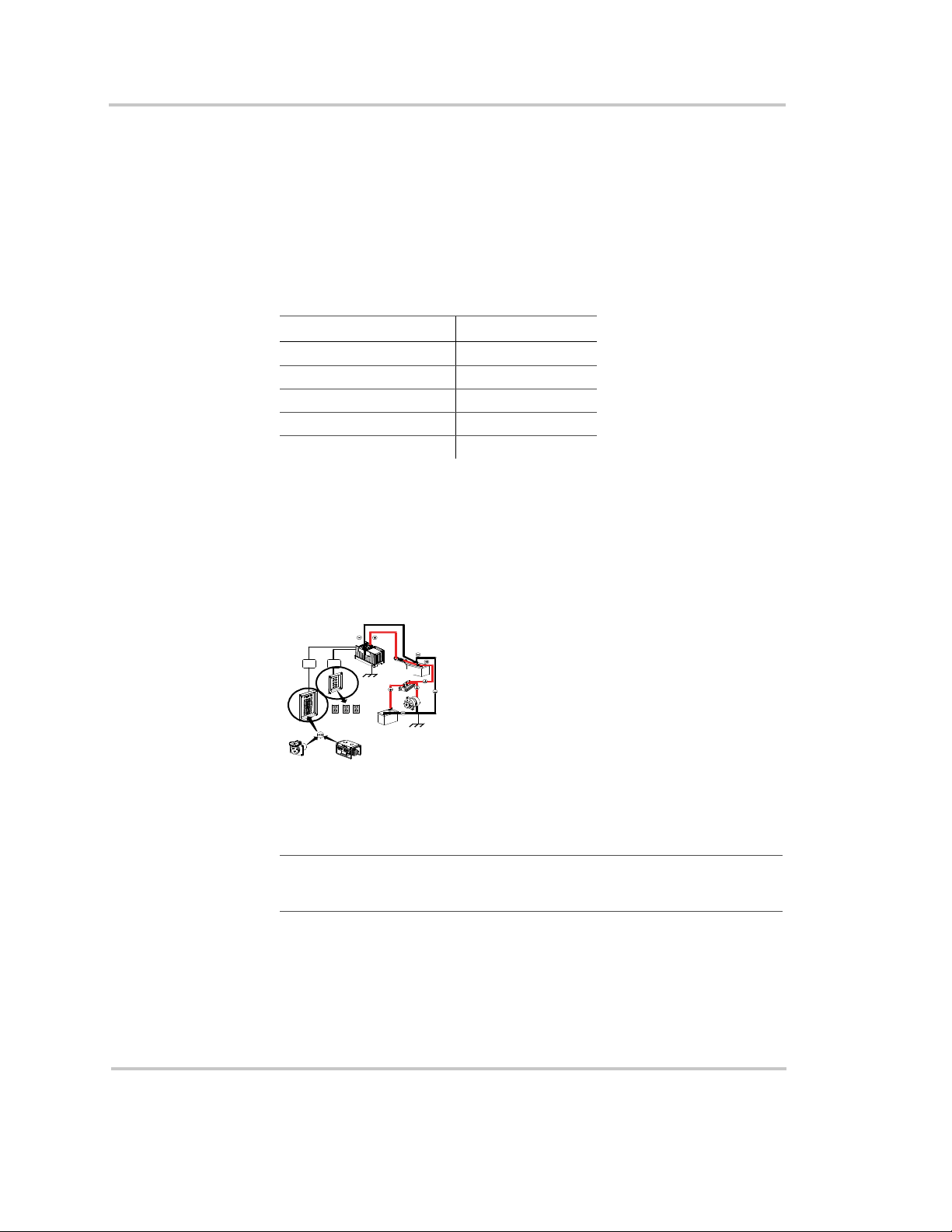
3. With the digital voltmeter leads placed directly on the battery studs,
measure the voltage at the battery between the positive and negative
terminals (3 and 4) while the load is operating.
4
3
F
us
e
d
a
is
n
co
d
o
r D
nn
e
C
ct
B
2
re
a
ke
r
5
1
4. Check the DC voltage on the IP1012 studs (1 and 5) while the load is
operating.
5. Calculate the difference between the readings. The voltage difference
should be as follows:
Load size
1000–1500
watts
Voltage drop
with fuse
less than 0.35
VDC
Voltage drop
without fuse
less than 0.2 VDC
6. If the voltage difference is greater than shown in the table, shut the
system down and re-check the tightness of all connections.
To measure the individual connection voltage drop:
1. Place one voltmeter test lead on the battery cable lug and the other on
the stud (or terminal) to which it is connected. Check to see that the
voltage drop (with full load test current) is less than 0.003 mV
(3 mV).
2. Perform this voltage check between all stud and lug connections
including the fuse (or DC disconnect) terminals and battery cable
lugs.
Customer Service If tightening the connections does not result in the desired test results,
record the readings and call Xantrex Customer Service.
445-0173-01-01 Rev 1 2–17
Page 36

2–18 445-0173-01-01 Rev 1
Page 37

3
The batteries you use strongly affect the performance of the IP1012. It is
important to connect the inverter to the correct size and type of battery.
The information in Chapter 3 will help you select, connect, and
maintain batteries that are most appropriate for your application.
Battery Types and
Sizes
Page 38

Battery Types and Sizes
Battery Types
Automotive Starting Batteries
The lead-acid battery you are most familiar with is probably the starting
battery in your automobile. An automotive starting battery is designed to
deliver a large amount of current for a short period of time (so it can start
your engine). Only a small portion of the battery’s capacity is used when
starting the engine, and it is quickly recharged by the running engine.
This type of battery is not designed for repeated cycles where the battery
is almost completely discharged and then recharged. If it is used in this
kind of deep discharge service, it will wear out very rapidly.
Deep-Cycle Lead-Acid Batteries
Deep-cycle lead-acid batteries are designed for deep discharge service
where they will be repeatedly discharged and recharged. They are
marketed for use in recreational vehicles, boats, and electric golf carts—
so you may see them referred to as RV batteries, marine batteries, or golf
cart batteries.
For most applications of the IP1012, Xantrex recommends that you use
one or more deep-cycle batteries that are separated from the vehicle’s
starting battery by a battery isolator.
A battery isolator is a solid-state electronic circuit that allows equipment
to be operated from an auxiliary battery without danger of discharging the
vehicle’s starting battery. During vehicle operation, the battery isolator
automatically directs the charge from the alternator to the battery
requiring the charge. Figure 3-1 and Figure 3-2 show a battery isolator in
configurations for normal and heavy-duty loads.
Battery isolators are available at marine and RV dealers and most auto
parts stores.
Battery Size
CAUTION
The IP1012 must only be connected to batteries with a nominal
output voltage of 12 volts. The IP1012 will not operate from a 6
volt battery and may be damaged if connected to a 24 volt
battery.
Importance Battery size or capacity is as important as the battery type for efficient
operation of your loads. Xantrex recommends that you purchase as much
battery capacity as possible.
3–2 445-0173-01-01 Rev 1
Page 39

Estimating Battery Requirements
Battery Capacity
Standards
A number of different standards are used to rate battery energy storage
capacity. Automotive and marine starting batteries are normally rated in
cranking amps. This is not a relevant rating for continuous loads like an
inverter. Deep-cycle batteries use a more suitable rating system, either
“amp-hours” (“Ah”) or “reserve capacity” in minutes.
Battery Reserve Capacity Battery reserve capacity is a measure of
how long a battery can deliver a certain amount of current—usually 25
amps. For example, a battery with a reserve capacity of 180 minutes can
deliver 25 amps for 180 minutes before it is completely discharged.
Amp-hour (Ah) Capacity Amp-hour capacity is a measure of how
many amps a battery can deliver for a specified length of time—usually
20 hours. For example, a typical marine or RV battery rated for 100 Ah
can deliver 5 amps for 20 hours (5 A x 20 hours = 100 Ah).
This same battery can deliver a higher or lower current for less or more
time, limited approximately by the 100 Ah figure (for example, 50 A for 2
hours, or 200 A for 1/2 hour), but usually the capacity figure given is only
accurate at the specified rate (20 hours).
To calculate the battery capacity you require, read “Estimating Battery
Requirements” on page 3–3 and “Battery Sizing Example” on page 3–4,
and then complete the “Battery Sizing Worksheet” on page 3–5.
Estimating Battery Requirements
To determine how much battery capacity you need:
1. Determine how many watts are consumed by each appliance that you
will operate from the IP1012. You can normally find this on a label on
the product. If only the current draw is given, multiply it by 115 to get
the power consumption in watts.
2. Estimate how many hours each appliance will be operating each day.
3. Calculate the daily watt-hours needed for each appliance.
4. Add the total number of watt-hours needed for all the appliances and
multiply it by the number of days between charges.
5. Divide the total watt-hours of AC load between charges by 10. This
gives the battery Ah used between charges.
6. Double the total Ah used between charges to get the recommended
battery size in Ah.
See the battery sizing example that follows.
445-0173-01-01 Rev 1 3–3
Page 40

Battery Types and Sizes
Battery Sizing Example
This battery sizing example illustrates a typical calculation, assuming an
opportunity to charge the batteries every three days.
Appliance
TV & VCR 115 W 3 hours 345 Wh
Microwave oven 1500 W 15 min = 1/4
3 lamps, 60 W
each
Coffee maker 750 W 15 min = 1/4
Coffee grinder 100 W 1 min = 1/60
Hair dryer 1500 W 6 min = 1/10
Sewing machine 150 W 30 min = 1/2
Washing machine 1500 W 30 min = 1/2
Steam iron 700 W 6 min = 1/10
Total daily watt-hours of AC load 2674.20 Wh
x Number of days between charges 3
= Total watt-hours of AC load between charges 8022.60 Wh
Battery Ah used between charges (divide by 10) 802.70 Ah
Recommended Battery Bank Size in Ah (multiply by 2)1600 Ah
Daily watthours needed
for this
(A) Power
Consumption
(B) Operating
Time per Day
appliance
(= A x B)
375 Wh
hour
180 W 4 hours 720 Wh
187.50 Wh
hour
1.70 Wh
hour
150 Wh
hour
75 Wh
hour
750 Wh
hour
70 Wh
hour
This example illustrates how quickly your battery needs can escalate. To
reduce the required battery size, you can conserve energy by eliminating
or reducing the use of some loads or by re-charging more frequently.
When sizing your battery, resist the temptation to skip the last step of this
calculation (multiplying by 2). More capacity is better since you will have
more reserve capacity, be better able to handle large loads and surge loads,
and your battery won't be discharged as deeply. Battery life is directly
3–4 445-0173-01-01 Rev 1
Page 41

dependent on how deeply the battery is discharged. The deeper the
discharge, the shorter the battery life.
Battery Sizing Worksheet
Use the following worksheet to calculate your battery needs. To ensure
sufficient battery capacity, be generous when estimating the operating
time per day for each of the loads you will run.
Appliance
Using Multiple Batteries
Daily watt-
hours needed
(A)
Power
Consumption
(B)
Operating Time
per day
for this
appliance
(= A x B)
W hours Wh
W hours Wh
W hours Wh
W hours Wh
W hours Wh
Total daily watt-hours of AC load Wh
x Number of days between charges
= Total watt-hours of AC load between charges Wh
Battery Ah used between charges (divide by 10) Ah
Recommended Battery Bank Size in Ah (multiply by 2)Ah
Using Multiple Batteries
As your power requirements increase, you may need to use more than one
battery to obtain sufficient capacity. Read “Two Batteries Connected In
Parallel” and “Two Separate Battery Banks” to determine whether two
batteries or two battery banks are more appropriate for your applications.
W hours Wh
W hours Wh
W hours Wh
445-0173-01-01 Rev 1 3–5
Page 42

Battery Types and Sizes
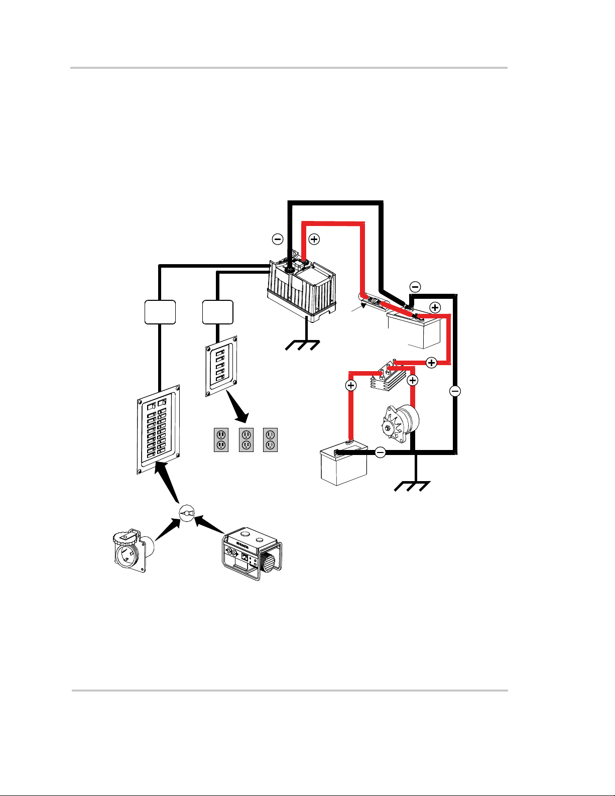
Two Batteries Connected In Parallel
Two identical batteries can be connected positive (+) to positive (+) and
negative (–) to negative (–) in a parallel system. A parallel system doubles
capacity and maintains the voltage of a single battery.
Figure 3-2 shows batteries connected in parallel. Figure 3-1 shows a
battery configuration suitable for normal loads; Figure 3-2 shows a
configuration that is recommended for heavy loads.
In these configurations, the IP1012 will charge any batteries connected to
it, but will not charge batteries through the battery isolator. The vehicle
starting batteries in the configuration shown in the figures will only be
charged by the alternator.
The deep cycle batteries can, however, be charged from the IP1012 and
the alternator. The batteries could be subject to a high charging current.
CAUTION
Do not connect the following in parallel: batteries made by
different manufacturers, different types of batteries, batteries
that have different Ah ratings. Decreased battery life and
improper charging will result.
ISOLATOR
GROUND TO
VEHICLE
CHASSIS
ODC
OADS
FUSEOR
CIRCUIT
BREAKER
T
L
FUSE OR
CIRCUIT
BREAKER
DEEP-CYCLE
AUXILIARY
BATTERY
Figure 3-1 Configuration for Normal Loads
FROM ALTERNATOR
OR CHARGER
VEHICLE
STARTING
BATTERY
TO VEHICLE
GROUND TO
VEHICLE
CHASSIS
3–6 445-0173-01-01 Rev 1
Page 43

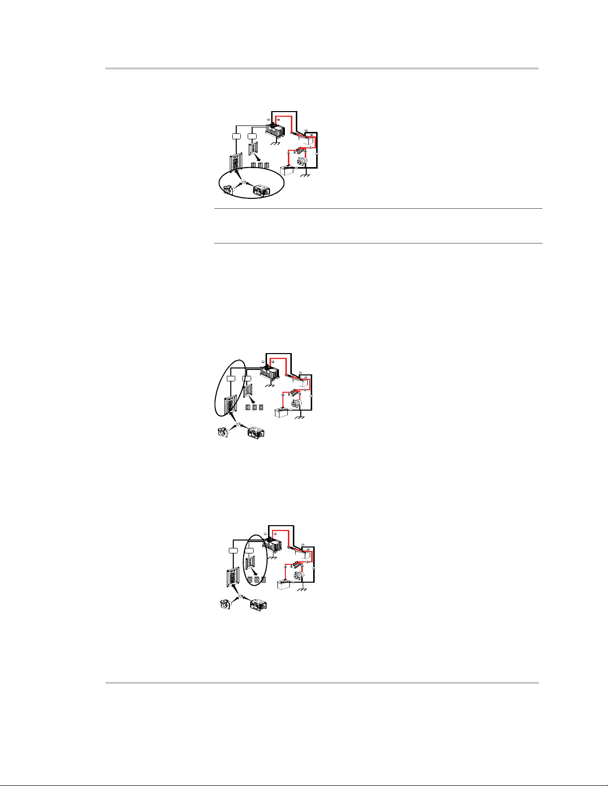
Two Separate Battery Banks
If you need more than two batteries (or are using different makes or
models of batteries), Xantrex recommends that you install two separate
battery banks and a battery selector switch.
Figure 3-2 shows two separate battery banks and a battery selector switch.
This configuration is recommended for heavy-duty applications.
Battery Tips
Battery Selector
Switch
By installing a battery selector switch, you can select between the two
battery banks, use both banks in parallel, or disconnect both banks from
the load. Battery selector switches are available at marine and RV dealers.
DEEP-CYCLE
BATTERY
DEEP-CYCL E
BATTERY
TO VEHI CLE
GROUND TO
VEHICLE
CHASSIS
GROUND TO
VEHICLE
CHASSIS
TO DC
LOADS
FROMALTERNATOR
OR CHARGER
ALL
1
OFF 2
BATTERY
SELECTOR
SWITCH
FUSE OR
CIRCUIT
BREAKER
BATTERYISOLATOR
DEEP-CYCLE
BATTERY
DEEP-CYCLE
BATTERY
FUSE OR
CIRCUIT
BREAKER
BATTERY
SELECTOR
SWITCH
ALL
OFF 2
VEHICLE
STARTING
BATTERY
FUSE OR
CIRC UIT
BREAKER
FUSE OR
CIRCUIT
BREAKER
1
BOTH
Figure 3-2 Configuration for Heavy Loads
Battery Tips
WARNING
Review the “Important Safety Instructions” before working
with the batteries in your system.
Explosive/Corrosive Gases Lead-acid batteries may emit hydrogen,
oxygen, and sulfuric acid fumes when recharging. To reduce the risk of
explosion:
445-0173-01-01 Rev 1 3–7
Page 44

Battery Types and Sizes
• Vent the battery compartment to prevent the accumulation of gases.
• Do not install electronic or electrical equipment which is not ignition
protected in the battery compartment.
• Do not smoke or use an open flame when working around batteries.
Temperature Sensitivity The capacity of lead-acid batteries is
temperature sensitive. Battery capacity is rated at 77º F (25º C). At 0º F
(–20º C), the Ah capacity is about half the rated capacity. You should
consider temperature when designing your system.
• Low Temperatures If extremely low temperatures are expected
where the inverter is going to be located, you should consider a
heated equipment room. If the system is located in an unheated
space, an insulated battery enclosure is recommended.
• High Temperatures The batteries should also be protected from
high temperatures. They can be caused by high ambient
temperatures, solar heating of the battery enclosure, or heat released
by a nearby engine or generator. High battery temperatures shorten
battery life and therefore you should ventilate the enclosure and use
shade and insulation as appropriate.
Discharged Batteries Do not leave batteries in a discharged state for
more than a day or two. They will undergo a chemical process (sulfation)
that can permanently damage the battery. As well, batteries self-discharge
over a period of three to six months, so they should be recharged
periodically even if they are not being used.
Electrolyte Level If your batteries are not the “maintenance-free” type,
check the electrolyte level at least once a month. Excessive fluid loss is a
sign of overcharging. Replenish the electrolyte using distilled water only.
Battery Connections Connections to battery posts must be made with
permanent connectors that provide a reliable, low-resistance connection.
Do not use alligator clips. Clean the connections regularly and prevent
corrosion by using a protective spray coating or vaseline.
3–8 445-0173-01-01 Rev 1
Page 45

Battery Tips
Battery State of Charge You can measure battery state of charge with
a hydrometer or, more easily, with a voltmeter. Use a digital voltmeter
than can display tenths or hundredths of a volt when measuring 10 to 30
volts. Make your measurements when the battery has not been charged or
discharged for several hours. For a deep-cycle battery at 77º F (25º C), use
the following table:
Battery Voltage State of Charge
12.7–13.0 100%
12.5–12.6 80%
12.3–12.4 60%
12.1–12.2 40%
11.9–12.0 20%
445-0173-01-01 Rev 1 3–9
Page 46

3–10 445-0173-01-01 Rev 1
Page 47

Index
A
AC circuit breaker 1–3
AC disconnect devices
AC distribution panel
AC fuses
AC input considerations
AC input cord, connecting
AC output considerations
AC output cord, connecting
AC output neutral bonding
AC wiring
Ah. See amp-hour capacity.
amp-hour (Ah) capacity
automotive starting marine
1–3
1–5
1–4
1–4
1–3
2–5
1–3
2–7
1–6
3–3
3–1
B
batteries
connecting in parallel
deep-cycle
discharged
first aid when working with
parallel connection illustrated
precautions when working with
temperature sensitivity
batteries, use of multiple
battery banks, separate
battery care tips
battery connections, maintaining
battery isolator, using
battery reserve capacity
battery selector switch
battery size
estimating example
estimating worksheet
battery state of charge, measuring
1–7
3–8
3–7
3–5
viii
3–8
3–5
3–6
3–2
3–2
3–7
3–3
3–5
3–6
viii
3–8
3–8
battery temperature sensor
attaching to battery terminal
attaching to side of battery
battery temperature sensor, installing
battery, automotive
bracket mounting
breaker ratings for AC wiring
BTS. See battery temperature sensor.
3–1
2–5
2–12
2–13
1–5
C
cable lengths, DC 1–6, 2–7
cable sizes, DC
chassis ground lug
circuit breakers, AC
connectors, recommended types
1–6
2–10, 2–11
1–3
2–5
D
DC cable lengths 1–6
DC cable sizes
DC cables, connecting
DC disconnect device
DC fuse sizes
DC grounding
recreational vehicle
residential
DC over-current device
deep-cycle battery
deep-cycle lead-acid battery, about
depth of discharge (DOD)
diagram, system
distribution panel, AC
1–6
2–7
1–7
1–6
2–11
2–11
1–7
1–7
3–2
3–4
1–2
1–4
E
electrolyte level, checking 3–8
2–11
Page 48

Index
F
FCC information to the user ix
first aid
floor mounting
fuse sizes
AC
DC
1–viii
2–4
1–3
1–6
G
gases, reducing risk of explosive 3–7
GFCI requirements
GFCIs, tested
ground wire sizes
groundwire, installing
1–4
1–4
2–11
2–10
I
ignition protection, safety implications 1–8
installation, testing
installation, tools and materials
inverter•charger
locating for installation
2–16
2–2
1–7
M
materials list 2–2
mounting template, diagram
mounting, considerations
multiple batteries
3–5
2–4
2–3
S
safety instructions vii–viii
shorepower, defined
single-phase wiring circuit
system diagram
system test after installation
1–3
1–4
1–2
2–16
T
temperature sensor 2–11
testing installation
transfer relay
2–16
1–5
V
ventilation, importance of 3–7
N
neutral bonding system, purpose of 1–5
neutral conductor
1–6
O
output cord, connecting 2–7
P
polarity, avoiding reverse 2–7
R
recreational vehicles, DC grounding 2–11
remote switch, enabling with
reserve capacity
reserve capacity in batteries
residential installations, DC grounding
reverse polarity, danger of
Index–2
3–2
2–16
3–2
2–11
2–7
 Loading...