

Page 1
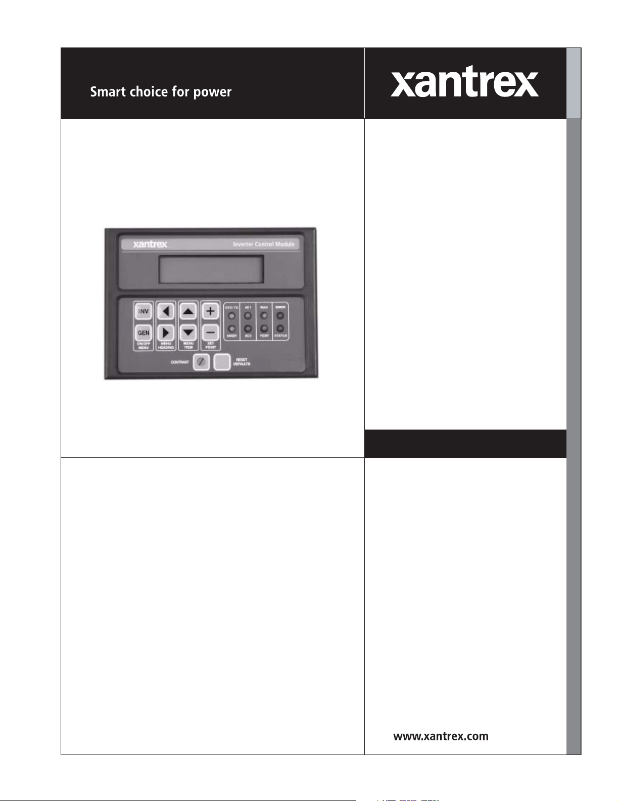
Inverter Control Module (ICM) Installation Guide
ICM
Installation Guide
Page 2

Page 3

Inverter Control Module
Installation Guide
Page 4

About Xantrex
Xantrex Technology Inc. is a world-leading supplier of advanced power electronics and controls with products from
50 watt mobile units to one MW utility-scale systems for wind, solar, batteries, fuel cells, microturbines, and backup
power applications in both grid-connected and stand-alone systems. Xantrex products include inverters, battery
chargers, programmable power supplies, and variable speed drives that convert, supply, control, clean, and distribute
electrical power.
Trademarks
Inverter Control Module is a trademark of Xantrex International. Xantrex is a registered trademark of Xantrex
International.
Other trademarks, registered trademarks, and product names are the property of their respective owners and are used
herein for identification purposes only.
Notice of Copyright
Inverter Control Module (ICM) Installation Guide © June 2003 Xantrex International. All rights reserved.
Disclaimer
UNLESS SPECIFICALLY AGREED TO IN WRITING, XANTREX TECHNOLOGY INC. (“XANTREX”)
(a) MAKES NO WARRANTY AS TO THE ACCURACY, SUFFICIENCY OR SUITABILITY OF ANY
TECHNICAL OR OTHER INFORMATION PROVIDED IN ITS MANUALS OR OTHER DOCUMENTATION.
(b) ASSUMES NO RESPONSIBILITY OR LIABILITY FOR LOSS OR DAMAGE, WHETHER DIRECT,
INDIRECT, CONSEQUENTIAL OR INCIDENTAL, WHICH MIGHT ARISE OUT OF THE USE OF SUCH
INFORMATION. THE USE OF ANY SUCH INFORMATION WILL BE ENTIRELY AT THE USER’S RISK.
Date and Revision
June 2003 Revision
Part Number
975-0058-01-01
Contact Information
Telephone: 1-800-446-6180 (toll free in North America)
1-360-435-8826 (direct)
Fax: 1-360-925-5143
Email: CustomerService@xantrex.com
Web: www.xantrex.com
Page 5

About This Guide
Purpose
The purpose of this Installation Guide is to provide explanations and
procedures for installing, operating, maintaining, and troubleshooting the
Inverter Control Module (ICM).
Scope
The Guide provides safety guidelines and procedures for installing the
ICM.
Audience
The Guide is intended for anyone who needs to install the ICM. Installers
should be certified technicians or electricians.
Organization
This Guide contains one chapter.
Chapter 1, “Installation” describes how to install the Inverter Control
Module (ICM).
Warranty and Product Information is provided at the end of the Guide.
975-0058-01-01 iii
Page 6
About This Guide
Conventions Used
The following conventions are used in this guide.
Note: These notes describe an important action item or an item that
you must pay attention to.
WARNING
Warnings identify conditions that could result in personal
injury or loss of life.
CAUTION
Cautions identify conditions or practices that could result in
damage to the unit or other equipment.
Important:
you to know, but not as serious as a caution or warning.
These notes describe things which are important for
Abbreviations and Acronyms
AC Alternating Current
ASC Authorized Service Center
DC Direct Current
ICM Inverter Control Module
RMA Return Material Authorization
Related Information
You can find more information about Xantrex Technology Inc. as well as
its products and services at www.xantrex.com
iv 975-0058-01-01
Page 7

Important Safety Instructions
WARNING
This section contains important safety and operating
instructions for Inverter Control Modules (ICM) used in
residential applications. Read and keep this Installation
Guide for future reference.
1. Before installing the ICM, read all instructions and cautionary
markings on the ICM, the batteries, and all appropriate sections of
this guide.
2. Do not expose the ICM to rain, snow, or spray.
3. Use only attachments recommended or sold by the manufacturer.
Doing otherwise may result in a risk of fire, electric shock, or injury
to persons.
4. The remote ICM is an optional accessory designed to be permanently
connected to your inverter and is intended to be used in addition to
the one that originally comes with the inverter. Do not remove the
ICM that originally comes with the inverter.
5. Installations of this equipment should only be performed by skilled
personnel such as qualified electricians and Certified Renewable
Energy (RE) System Installers to ensure adherence to the local and
national electrical codes applicable in your application. For a list of
Xantrex Certified RE dealers, please visit our website at
www.XantrexREdealers.com.
6. Do not install the ICM if it has received a sharp blow, been dropped,
or otherwise damaged in any way. If the unit is damaged, see the
Warranty section at the end of this guide.
7. Do not disassemble the ICM. See “How do you get service?” on
page WA–1 for instructions on obtaining service. Attempting to
service the unit yourself may result in a risk of electrical shock or fire.
8. To reduce the risk of electrical shock, disconnect the ICM from the
inverter before attempting any maintenance or cleaning or working on
any circuits connected to the ICM.
975-0058-01-01 v
Page 8

Important Safety Instructions
FCC information to the user
This equipment has been tested and found to comply with the limits for a
Class B digital device, pursuant to part 15 of the FCC Rules. These limits
are designed to provide reasonable protection against harmful
interference in a residential installation. This equipment generates, uses
and can radiate radio frequency energy and, if not installed and used in
accordance with the instructions, may cause harmful interference to radio
communications. However, there is no guarantee that interference will not
occur in a particular installation. If this equipment does cause harmful
interference to radio or television reception, which can be determined by
turning the equipment off and on, the user is encouraged to try to correct
the interference by one or more of the following measures:
• Reorient or relocate the receiving antenna.
• Increase the separation between the equipment receiver.
• Connect the equipment into an outlet on a circuit different from that
to which the receiver is connected.
• Consult the dealer or an experienced radio/TV technician for help.
vi 975-0058-01-01
Page 9

Contents
Important Safety Instructions
Installation
Introduction - - - - - - - - - - - - - - - - - - - - - - - - - - - - - - - - - - - - - - - - - - - - - - - - - - - - -1–2
Specifications - - - - - - - - - - - - - - - - - - - - - - - - - - - - - - - - - - - - - - - - - - - - - - - - -1–2
Code Compliance - - - - - - - - - - - - - - - - - - - - - - - - - - - - - - - - - - - - - - - - - - - - - - - - -1–4
Installation Tools and Materials- - - - - - - - - - - - - - - - - - - - - - - - - - - - - - - - - - - - - - - -1–4
Planning your Installation- - - - - - - - - - - - - - - - - - - - - - - - - - - - - - - - - - - - - - - - - - - -1–4
Installing the ICM - - - - - - - - - - - - - - - - - - - - - - - - - - - - - - - - - - - - - - - - - - - - - - - - -1–5
The ICM Adapter Sleeve - - - - - - - - - - - - - - - - - - - - - - - - - - - - - - - - - - - - - - -1–5
ICM Mounting Bracket - - - - - - - - - - - - - - - - - - - - - - - - - - - - - - - - - - - - - - - -1–6
Flush-Mount Installation - - - - - - - - - - - - - - - - - - - - - - - - - - - - - - - - - - - - - - - - - -1–7
Surface-Mount Installation - - - - - - - - - - - - - - - - - - - - - - - - - - - - - - - - - - - - - - -1–11
Warranty - - - - - - - - - - - - - - - - - - - - - - - - - - - - - - - - - - - - - - - - - - - - - - - - - - - - -WA–1
Return Material Authorization Policy- - - - - - - - - - - - - - - - - - - - - - - - - - - - - - - - - -WA–3
Out of Warranty Service - - - - - - - - - - - - - - - - - - - - - - - - - - - - - - - - - - - - - - - - - -WA–4
Information About Your System - - - - - - - - - - - - - - - - - - - - - - - - - - - - - - - - - - - - -WA–4
975-0058-01-01 vii
Page 10

viii
Page 11

Figures
Figure 1-1 The Inverter Control Module (ICM)- - - - - - - - - - - - - - - - - - - - - - - - - - - -1–2
Figure 1-2 ICM component parts, front and back views - - - - - - - - - - - - - - - - - - - - - -1–3
Figure 1-3 ICM Adapter Sleeve (not to scale) - - - - - - - - - - - - - - - - - - - - - - - - - - - - -1–5
Figure 1-4 ICM Mounting Bracket (not to scale) - - - - - - - - - - - - - - - - - - - - - - - - - - -1–6
Figure 1-5 ICM mounting bracket on wall, flush mount cut line- - - - - - - - - - - - - - - - -1–7
Figure 1-6 Disassembling the ICM plug- - - - - - - - - - - - - - - - - - - - - - - - - - - - - - - - -1–8
Figure 1-7 Inserting ICM cable into conduit - - - - - - - - - - - - - - - - - - - - - - - - - - - - - -1–9
Figure 1-8 ICM Attached to Faceplate for Flush Mounting - - - - - - - - - - - - - - - - - - - -1–9
Figure 1-9 Mounting the Faceplate to the Mounting Bracket - - - - - - - - - - - - - - - - - -1–10
Figure 1-10 Sine Wave Plus Inverter/Charger Remote Port Location - - - - - - - - - - - - - 1–10
Figure 1-11 ICM Mounting Bracket on Wall, Panel Mount Cut Line - - - - - - - - - - - - -1–11
Figure 1-12 ICM and Adapter Sleeve Attached to the Faceplate for Surface Mounting - 1–12
Figure 1-13 Mounting the ICM with Adapter Sleeve to the Mounting Bracket- - - - - - - 1–12
975-0058-01-01 ix
Page 12

x
Page 13

1
Installation
Chapter 1, “Installation” describes how to install the Inverter
Control Module (ICM).
The following topics are covered in this chapter.
See: for this topic:
page 1–2 “Introduction”
page 1–2 “Specifications”
page 1–4 “Code Compliance”
page 1–4 “Installation Tools and Materials”
page 1–4 “Planning your Installation”
page 1–5 “Installing the ICM”
Page 14

Installation
Introduction
The Inverter Control Module (ICM) allows remote monitoring and
adjustment of all settings on a Sine Wave Plus inverter. It can be installed
up to 50 feet/15 meters from the inverter itself. The ICM (Figure 1-1)
provides a remote Control Module identical to the Control Module on the
inverter and can be operated in the same way.
Figure 1-1
For more information on operating the ICM, please consult your Sine
Wave Plus inverter owner’s manual because the firmware and settings
reside in the inverter.
The Inverter Control Module (ICM)
Specifications
The ICM is available with two cable lengths.
• ICM/25 with 25 foot/7.5 meter communications cable
• ICM/50 with 50 foot/15 meter communications cable
The ICM consists of:
•the ICM faceplate, containing the LCD display and buttons used to
control the inverter
• one adapter sleeve for use in the surface mount configuration
• one mounting bracket for attaching the assembly to the wall
• 4 screws and expansion plugs for attaching mounting bracket to wall
• a 25 or 50 foot communications cable with DB25 connectors.
1–2 975-0058-01-01
Page 15

LCD
Display
Introduction
ICM Faceplate
Push
buttons
Contrast
Adjustment
RESET
DEFAULTS
button
LED
Display
DB25 Connector
DB25 Port for ICM
Communications Cable
ICM
Communications
Cable
DB25 Connector
Back of ICM Faceplate
Adapter Sleeve
Figure 1-2
(for surface-mounting)
ICM component parts, front and back views
Mounting Bracket
975-0058-01-01 1–3
Page 16

Installation
Code Compliance
Governing installation codes vary depending on the location and type of
installation. Electrical installations must meet local and national wiring
codes and should be done by a qualified electrician.
Important:
prior to starting this installation.
Be sure to obtain the appropriate permits, if necessary,
Installation Tools and Materials
Tools Required The following tools may be required for installing this equipment.
❐ Pencil
❐ Level
❐ Wallboard/sheetrock saw
❐ Phillips screw driver
❐ 3/32" and 3/16" drill bits
❐ Electric drill
❐ Electrician’s fish tape
Hardware /
Materials Required
❐ Wire conduit
❐ Packing tape
Planning your Installation
Determine the wire route to the inverter. The ICM should be mounted
in/on a wall no more than 50 feet/15 meters or 25 feet/7.5 meters from the
inverter, depending on whether it is the ICM/25 or the ICM/50.
Important: Mount the remote control in a clean, dry environment.
Verify there are no electrical wires, etc., in the area of the cut.
1–4 975-0058-01-01
Page 17

Installing the ICM
The ICM can be flush-mounted (only the faceplate protrudes from the
wall) or surface-mounted (the entire assembly protrudes from the wall).
In the flush-mount configuration the ICM faceplate is attached directly to
the mounting bracket on the wall. In the surface-mount configuration the
ICM faceplate is first attached to the adapter bracket, which is then
attached to the mounting bracket on the wall.
Ensure that there is enough space within the wall for the mounting format
you choose.
The ICM Adapter Sleeve
The ICM adapter sleeve is used for surface-mounting the ICM faceplate.
It attaches to the ICM mounting bracket. It is not used if the faceplate is to
be flush-mounted.
Installing the ICM
WARNING: Electrical Hazard
Ensure that no DC voltage is being supplied to the inverter, and
that no AC voltage is present on the AC wiring. Failure to do so
could cause serious injury or death.
Figure 1-3
975-0058-01-01 1–5
ICM Adapter Sleeve (not to scale)
Page 18

Installation
ICM Mounting Bracket
The ICM mounting bracket is used for both flush-mounting and
surface-mounting.
Figure 1-4
1–6 975-0058-01-01
ICM Mounting Bracket (not to scale)
Page 19

Flush-Mount Installation
There are three major steps to flush-mounting the ICM in a wall:
• Install the ICM mounting bracket on the wall (below)
• Route the ICM cable in the wall (page 1–8)
• Attach the ICM to the wall and connect the cable to the inverter
(page 1–9).
These steps are described in detail below.
Installing the ICM
Install the ICM
mounting bracket
on the wall
To install the ICM mounting bracket on the wall:
1. Use the mounting bracket as a template and mark the positions for the
screw holes. Mark the open area to be cut out for the circuit board.
ICM
mounting
bracket
cut line
for flush
mount
Figure 1-5
ICM mounting bracket on wall, flush mount cut line
2. Carefully cut out the circuit board area from the backing material
(i.e., wallboard). Cut inside the lines so there is enough area left to
securely hold the screws.
3. Remove any wall insulation (if applicable) that may contact the back
of the ICM.
Important: There must be at least 4" clearance behind the
opening to accommodate the DB25 connector that plugs into the
back of the ICM.
975-0058-01-01 1–7
Page 20

Installation
4. Drill out the four screw’s holes (if required) and cut out the wire
access opening. Use a 3/16" bit if the supplied plastic anchors are
used. If placing the screws directly into the backing material, use a
3/32" bit.
5. Install the mounting bracket on the wall using the screws (and
anchors if necessary) supplied. Do not overtighten the screws.
Route the ICM
cable in the wall
To route the ICM cable in the wall:
1. Route a wire conduit from the AC end of the inverter (or ACCB
accessory if installed) up to the opening in the wall. Insert
electrician’s fish tape in the end of the conduit at the wall opening
until the end appears at the inverter end of the conduit.
Note: The ICM cable should be able to fit through most 1 ¼"
conduit fittings. The conduit for the ICM cable should not contain
other AC or DC power conductors.
2. Unscrew the two screws and nuts from the connector housing of one
of the ICM cable plugs and carefully remove the plastic housing (two
pieces) from the plug, leaving the wires and DB25 connector attached
to the cable (Figure 1-6).
Connector
Housing
ICM
Cable
Screws for
atttaching this
cable to the port
Connector
Screws and nuts
for the Connector
Housing
Figure 1-6
Disassembling the ICM plug
Housing
1–8 975-0058-01-01
Page 21

Installing the ICM
3. Carefully tape the connector to the end of the fish tape, so that it will
fit into the conduit without damaging the connector or attached wires
(see Figure 1-7).
1
Figure 1-7
3
Inserting ICM cable into conduit
2
4
4. Pull the ICM cable up to the wall opening with the fish tape.
5. Re-assemble the plug using the two screws and nuts removed earlier
to re-attach the plastic housing to the connector and cable.
Attach the ICM to
the wall and connect
to the inverter
975-0058-01-01 1–9
To attach the ICM flush to the wall:
1. Plug the DB25 connector into the DB25 Port on the back of the ICM
faceplate. Secure with the two screws provided.
ICM Faceplate, rear view
DB25 Port
Screws for securing DB25
Connector to DB25 Port (x2)
DB25 Connector
ICM Cable
Figure 1-8
ICM Attached to Faceplate for Flush Mounting
Page 22

Installation
2. Snap the faceplate onto the mounting bracket on the wall.
ICM Faceplate
Mounting Bracket
Figure 1-9
Mounting the Faceplate to the Mounting Bracket
3. Plug the other end of the communications cable into the Remote Port
on the AC side of the inverter (Figure 1-10). Secure with the two
screws provided.
Remote Port
AC Side
Figure 1-10
1–10 975-0058-01-01
Sine Wave Plus inverter Remote Port Location
Page 23

Surface-Mount Installation
Surface-mounting the ICM on a wall follows the same major steps as for
flush-mounting (page 1–7), except for the differences noted below.
Installing the ICM
Install the ICM
mounting bracket
on the wall
To install the ICM mounting bracket on the wall:
1. Follow the instructions for installing the ICM mounting bracket on
page 1–7 except for step 2, which is replaced by the following:
2. Carefully cut out a rectangular area (2
½" wide x 1" deep, and 0.2"
down from the inside top middle of the wall mounting bracket) from
the backing material (i.e., wallboard).
This opening should be large enough to accommodate the ICM cable
plug, and be positioned immediately behind the connector on the ICM
when the faceplate and adapter sleeve is mounted on the bracket.
0.2” gap
1”
2.5”
cut line for panel mount
ICM mounting bracket
Install the ICM
cable in the wall
Figure 1-11
To install the ICM cable in the wall:
◆ Follow the instructions for installing the ICM cable in the wall on
ICM Mounting Bracket on Wall, Panel Mount Cut Line
page 1–8, exactly as stated.
Attach the ICM to
the wall and connect
to the inverter
To attach the ICM to the wall:
1. Snap the ICM faceplate onto the adapter sleeve provided with your
ICM kit.
1. Plug the DB25 connector into the DB25 Port on the back of the ICM
display panel. Secure with the two screws provided.
975-0058-01-01 1–11
Page 24

Installation
DB25 Port
DB25
Connector
Adapter Sleeve
Faceplate Rear View
ICM Cable
Figure 1-12
ICM and Adapter Sleeve Attached to the Faceplate for
Surface Mounting
2. Snap the adapter sleeve onto the mounting bracket (on the wall).
ICM Faceplate
Figure 1-13
Mounting the ICM with Adapter Sleeve to the
Adapter Sleeve
Mounting Bracket
Mounting Bracket
3. Plug the other end of the communications cable into the Remote Port
on the AC side of the inverter (Figure 1-10 on page 1–10) and secure
with the two screws provided.
1–12 975-0058-01-01
Page 25

Warranty and Product Information
Warranty
What does this warranty cover? This Limited Warranty is provided by Xantrex Technology, Inc.
("Xantrex") and covers defects in workmanship and materials in your Inverter Control Module. This warranty
lasts for a Warranty Period of two (2) years from the date of purchase at point of sale to you, the original end
user customer.
This Limited Warranty is transferable to subsequent owners but only for the unexpired portion of the Warranty
Period.
What will Xantrex do? Xantrex will, at its option, repair or replace the defective product free of charge,
provided that you notify Xantrex of the product defect within the Warranty Period, and provided that Xantrex
through inspection establishes the existence of such a defect and that it is covered by this Limited Warranty.
Xantrex will, at its option, use new and/or reconditioned parts in performing warranty repair and building
replacement products. Xantrex reserves the right to use parts or products of original or improved design in the
repair or replacement. If Xantrex repairs or replaces a product, its warranty continues for the remaining
portion of the original Warranty Period or 90 days from the date of the return shipment to the customer,
whichever is greater. All replaced products and all parts removed from repaired products become the property
of Xantrex.
Xantrex covers both parts and labor necessary to repair the product, and return shipment to the customer via a
Xantrex-selected non-expedited surface freight within the contiguous United States and Canada. Alaska and
Hawaii are excluded. Contact Xantrex Customer Service for details on freight policy for return shipments
outside of the contiguous United States and Canada.
How do you get service? If your product requires troubleshooting or warranty service, contact your
merchant. If you are unable to contact your merchant, or the merchant is unable to provide service, contact
Xantrex directly at:
Phone: 1-800-446-6180 (toll free)
1-360-435-8826 (direct)
Fax: 1-360-925-5143
Email: CustomerService@xantrex.com
Direct returns may be performed according to the Xantrex Return Material Authorization Policy described in
your product manual. For some products, Xantrex maintains a network of regional Authorized Service
Centers. Call Xantrex or check our website to see if your product can be repaired at one of these facilities.
In any warranty claim, dated proof of purchase must accompany the product and the product must not have
been disassembled or modified without prior written authorization by Xantrex.
975-0058-01-01 WA–1
Page 26

Proof of purchase may be in any one of the following forms:
• The dated purchase receipt from the original purchase of the product at point of sale to the end user, or
• The dated dealer invoice or purchase receipt showing original equipment manufacturer (OEM) status, or
• The dated invoice or purchase receipt showing the product exchanged under warranty
What does this warranty not cover? This Limited Warranty does not cover normal wear and tear of the
product or costs related to the removal, installation, or troubleshooting of the customer's electrical systems.
This warranty does not apply to and Xantrex will not be responsible for any defect in or damage to:
a) the product if it has been misused, neglected, improperly installed, physically damaged or altered, either
internally or externally, or damaged from improper use or use in an unsuitable environment;
b) the product if it has been subjected to fire, water, generalized corrosion, biological infestations, or input
voltage that creates operating conditions beyond the maximum or minimum limits listed in the Xantrex
product specifications including high input voltage from generators and lightning strikes;
c) the product if repairs have been done to it other than by Xantrex or its authorized service centers (hereaf-
ter "ASCs");
d) the product if it is used as a component part of a product expressly warranted by another manufacturer;
e) the product if its original identification (trade-mark, serial number) markings have been defaced, altered,
or removed.
Disclaimer
Product
THIS LIMITED WARRANTY IS THE SOLE AND EXCLUSIVE WARRANTY PROVIDED BY XANTREX IN CONNECTION
WITH YOUR XANTREX PRODUCT AND IS, WHERE PERMITTED BY LAW, IN LIEU OF ALL OTHER WARRANTIES,
CONDITIONS, GUARANTEES, REPRESENTATIONS, OBLIGATIONS AND LIABILITIES, EXPRESS OR IMPLIED,
STATUTORY OR OTHERWISE IN CONNECTION WITH THE PRODUCT, HOWEVER ARISING (WHETHER BY CONTRACT,
TORT, NEGLIGENCE, PRINCIPLES OF MANUFACTURER'S LIABILITY, OPERATION OF LAW, CONDUCT, STATEMENT OR
OTHERWISE), INCLUDING WITHOUT RESTRICTION ANY IMPLIED WARRANTY OR CONDITION OF QUALITY,
MERCHANTABILITY OR FITNESS FOR A PARTICULAR PURPOSE. ANY IMPLIED WARRANTY OF MERCHANTABILITY
OR FITNESS FOR A PARTICULAR PURPOSE TO THE EXTENT REQUIRED UNDER APPLICABLE LAW TO APPLY TO THE
PRODUCT SHALL BE LIMITED IN DURATION TO THE PERIOD STIPULATED UNDER THIS LIMITED WARRANTY.
IN NO EVENT WILL XANTREX BE LIABLE FOR ANY SPECIAL, DIRECT, INDIRECT, INCIDENTAL OR CONSEQUENTIAL
DAMAGES, LOSSES, COSTS OR EXPENSES HOWEVER ARISING WHETHER IN CONTRACT OR TORT INCLUDING
WITHOUT RESTRICTION ANY ECONOMIC LOSSES OF ANY KIND, ANY LOSS OR DAMAGE TO PROPERTY, ANY
PERSONAL INJURY, ANY DAMAGE OR INJURY ARISING FROM OR AS A RESULT OF MISUSE OR ABUSE, OR THE
INCORRECT INSTALLATION, INTEGRATION OR OPERATION OF THE PRODUCT.
Exclusions
If this product is a consumer product, federal law does not allow an exclusion of implied warranties. To the
extent you are entitled to implied warranties under federal law, to the extent permitted by applicable law they
are limited to the duration of this Limited Warranty. Some states and provinces do not allow limitations or
exclusions on implied warranties or on the duration of an implied warranty or on the limitation or exclusion of
incidental or consequential damages, so the above limitation(s) or exclusion(s) may not apply to you. This
Limited Warranty gives you specific legal rights. You may have other rights which may vary from state to
state or province to province.
WA–2 975-0058-01-01
Page 27

Return Material Authorization Policy
Warning: Limitations On Use
Please refer to your product manual for limitations on uses of the product.
SPECIFICALLY, PLEASE NOTE THAT THE INVERTER CONTROL MODULE SHOULD NOT BE USED IN CONNECTION
WITH LIFE SUPPORT SYSTEMS OR OTHER MEDICAL EQUIPMENT OR DEVICES. WITHOUT LIMITING THE GENERALITY
OF THE FOREGOING, XANTREX MAKES NO REPRESENTATIONS OR WARRANTIES REGARDING THE USE OF THE
XANTREX INVERTER CONTROL MODULE IN CONNECTION WITH LIFE SUPPORT SYSTEMS OR OTHER MEDICAL
EQUIPMENT OR DEVICES.
Please note that the Inverter Control Module is not intended for use as an uninterruptible power supply and
Xantrex makes no warranty or representation in connection with any use of the product for such purposes.
Return Material Authorization Policy
Before returning a product directly to Xantrex you must obtain a Return Material Authorization (RMA)
number and the correct factory "Ship To" address. Products must also be shipped prepaid. Product shipments
will be refused and returned at your expense if they are unauthorized, returned without an RMA number
clearly marked on the outside of the shipping box, if they are shipped collect, or if they are shipped to the
wrong location.
When you contact Xantrex to obtain service, please have your instruction manual ready for reference and be
prepared to supply:
• The serial number of your product
• Information about the installation and use of the unit
• Information about the failure and/or reason for the return
• A copy of your dated proof of purchase
Record these details in on page WA–4.
Return Procedure
1. Package the unit safely, preferably using the original box and packing materials. Please ensure that your
product is shipped fully insured in the original packaging or equivalent. This warranty will not apply
where the product is damaged due to improper packaging.
2. Include the following:
• The RMA number supplied by Xantrex Technology, Inc. clearly marked on the outside of the box.
• A return address where the unit can be shipped. Post office boxes are not acceptable.
• A contact telephone number where you can be reached during work hours.
• A brief description of the problem.
3. Ship the unit prepaid to the address provided by your Xantrex customer service representative.
If you are returning a product from outside of the USA or Canada In addition to the above, you
MUST include return freight funds and are fully responsible for all documents, duties, tariffs, and deposits.
If you are returning a product to a Xantrex Authorized Service Center (ASC) A Xantrex return
material authorization (RMA) number is not required. However, you must contact the ASC prior to returning
the product or presenting the unit to verify any return procedures that may apply to that particular facility.
975-0058-01-01 WA–3
Page 28

Out of Warranty Service
If the warranty period for your Inverter Control Module has expired, if the unit was damaged by misuse or
incorrect installation, if other conditions of the warranty have not been met, or if no dated proof of purchase is
available, your inverter may be serviced or replaced for a flat fee.
To return your Inverter Control Module for out of warranty service, contact Xantrex Customer Service for a
Return Material Authorization (RMA) number and follow the other steps outlined in “Return Procedure” on
page WA–3.
Payment options such as credit card or money order will be explained by the Customer Service
Representative. In cases where the minimum flat fee does not apply, as with incomplete units or units with
excessive damage, an additional fee will be charged. If applicable, you will be contacted by Customer Service
once your unit has been received.
Information About Your System
As soon as you open your Inverter Control Module package, record the following information and be sure to
keep your proof of purchase.
❐ Purchased From
❐ Purchase Date
_________________________________
_________________________________
WA–4 975-0058-01-01
Page 29

Index
A
Abbreviations and Acronyms iv
attach the ICM to the wall bracket
flush mount
panel mount 1–11
1–9
C
connect the ICM to the inverter 1–9
Customer Service
email
WA–1
fax number WA–1
phone number WA–1
D
distance from inverter 1–4
E
email, contacting Customer Service by WA–1
F
fax number for Customer Service WA–1
FCC information to the user 1–vi
flush mount installation 1–7
M
mount the ICM bracket on the wall
flush mount
panel mount 1–11
1–7
P
proof of purchase WA–4
purchase date WA–4
R
remote port location on inverter 1–10
return material authorization (RMA) policy WA–3
return procedure under warranty WA–3
RMA number WA–4
S
safety instructions v–??
surface mount installation 1–11
T
telephone number for Customer Service WA–1
tools required for installation 1–4
I
Information about Your System form WA–4
install the ICM cable in the wall 1–8
installation
codes
1–4
distance from inverter 1–4
flush mount 1–7
surface mount 1–11
tools required 1–4
inverter
purchase date
Inverter Control Module (ICM) 1–2
distance from inverter 1–4
installing 1–7
specifications 1–2
tools for installing 1–4
WA–4
W
warranty
out of warranty service
return material authorization policy WA–3
return under warranty WA–3
terms and conditions WA–1
WA–4
X
Xantrex
Authorized Service Center (ASC)
3
Customer Service WA–1, WA–4
web site iv
WA–1, WA–
Page 30

IX–2
Page 31

Page 32

Xantrex Technology Inc.
360 438 8826 Tel
360 925 5143 Fax
800 446 6180 Toll Free North America
customerservice@xantrex.com
www.xantrex.com
975-0058-01-01 Rev A
Printed in USA
 Loading...