


Operating Instructions — Parts Manual
14-Inch Vertical Band Saws
Models: 8201, 8203, 8201VS and 8203VS
WHM TOOL GROUP |
|
2420 Vantage Drive |
|
Elgin, Illinois 60123 |
Part No. 9078171 |
Ph.: 800-274-6848 |
Revision C2 04/07 |
www.wmhtoolgroup.com |
Copyright © 2007 WMH Tool Group |

Table of Contents |
|
Cover Page.................................................................................................. |
1 |
General Specifications ................................................................................. |
4 |
Operating Precautions ................................................................................. |
5 |
Set-up and Operation ................................................................................... |
7 |
Wiring Diagrams .......................................................................................... |
8 |
Operating Instructions ................................................................................ |
10 |
Maintenance .............................................................................................. |
14 |
Troubleshooting.......................................................................................... |
18 |
Replacement Parts..................................................................................... |
19 |
3
General Specifications
Wilton’s 14-inch Tradesman Vertical Band Saws are specially designed to effectively cut a variety of materials including wood, plastic, bakelite, composites, ferrous and non-ferrous metals. Models 8201 and 8203 are wood and metal cutting band saws.
Wilton’s Model 8201VS and 8203VS 14-inch Tradesman Variable Speed Band Saws are ideally suited for metal cutting only with an infinitely variable speed range from 116 to 334 SFPM. The variable speed drive system allows the operator to fine-tune the blade speed to the material being cut to maximize the life of today’s bi-metal blades. These versatile and dependable saws are capable of contour cutting, straight cutting and re-sawing, and these band saws can cut delicate curves in thick or thin stock.
4 |
Specifications |
|
|
|
|
|
Capacity |
8201 |
8203 |
8201VS |
8203VS |
|
Standard .............. |
6-in. under guide ..... |
6-in. under guide ....... |
6-in. under guide ...... |
6-in. under guide |
|
With 12-in. Riser .. |
12-in. under guide ... |
12-in. under guide ..... |
12-in. under guide .... |
12-in. under guide |
|
Blade to frame ..... |
13.5-in. .................... |
13.5-in. ..................... |
13.5-in. ..................... |
13.5-in. |
|
Motor |
1 HP 1-Ph |
1 HP 3-Ph |
1 HP 1-Ph |
1 HP 3-Ph |
|
Rating .................. |
||||
|
Voltage................. |
115 vac.................... |
220/440 vac .............. |
115 vac .................... |
220/440 vac |
|
Speed .................. |
1725 rpm ................. |
1725 rpm .................. |
1725 rpm.................. |
1725 rpm |
|
Cutting Speeds |
3300 |
3300 |
2600 |
2600 |
|
Wood (SFPM) ...... |
||||
|
Metal (SFPM) ....... |
39, 57, 78, 107, ....... 39, 57, 78, 107, ........ 116 – 334 ................. |
116 – 334 |
||
|
Dimensions |
142, 196, 278 .......... |
142, 196, 278 ............ |
Variable Speed ......... |
Variable Speed |
|
20 Inches |
20 Inches |
20 Inches |
20 Inches |
|
|
Length ................. |
||||
|
Width ................... |
16 Inches ................ |
16 Inches .................. |
16 Inches ................. |
16 Inches |
|
Height .................. |
66 Inches ................ |
66 Inches .................. |
66 Inches ................. |
66 Inches |
|
Height from Floor ..... |
66 Inches ................ |
66 Inches .................. |
66 Inches ................. |
66 Inches |
|
Table Tilt to Right ..... |
45 Degrees ............. |
45 Degrees ............... |
45 Degrees .............. |
45 Degrees |
|
Table Tilt to Left ....... |
10 Degrees ............. |
10 Degrees ............... |
10 Degrees .............. |
10 Degrees |
|
Miter Gauge Groove |
3/4-Inch |
3/4-Inch |
3/4-Inch |
3/4-Inch |
|
Width ................... |
||||
|
Depth ................... |
3/8-Inch ................... |
3/8-Inch .................... |
3/8-Inch .................... |
3/8-Inch |
|
Miter Gauge ............. |
Standard .................. |
Standard ................... |
Standard .................. |
Standard |
|
Blade Dimension |
3/8x0.025x92.5 In |
3/8x0.025x92.5 In |
3/8x0.025x92.5 In |
3/8x0.025x92.5 In. |
|
Standard .............. |
||||

|
|
|
|
|
|
|
|
|
|
|
|
- Misuse of this machine can cause serious injury. |
- Always follow instructions in Operating Instruc- |
||
- For safety, machine must be set up, used and |
tions and Parts Manual when changing acces- |
||
serviced properly. |
sory tools or parts. |
||
- Read, understand and follow instructions in the |
- Never modify the machine without consulting |
||
Operating Instructions and Parts Manual which |
Wilton Corporation. |
||
was shipped with your machine. |
You - the Stationary Power Tool User - Hold |
||
When Setting up Machine: |
the Key to Safety. |
||
- Always avoid using machine in damp or poorly |
Read and follow these simple rules for best results |
||
lighted work areas. |
and full benefits from your machine. Used properly, |
||
- Always be sure the machine support is se- |
Wilton’s machinery is among the best in design and |
||
curely anchored to the floor or the work bench. |
safety. However, any machine used improperly can |
||
When Using Machine: |
be rendered inefficient and unsafe. It is absolutely |
||
- Always wear safety glasses with side shields |
mandatory that those who use our products be |
||
(See ANSI Z87.1) |
properly trained in how to use them correctly. They |
||
- Never wear loose clothing or jewelry. |
should read and understand the Operating Instruc- |
||
- Never overreach - you may slip and fall. |
tions and Parts Manual as well as all labels affixed to |
||
When Servicing Machine: |
the machine. Failure to follow all of these warnings |
||
- Always disconnect the machine from its electri- |
can cause serious injuries. |
||
cal supply while servicing. |
|
|
|
Machinery General Safety Warnings |
|
|||
1. |
Always wear protective eye wear when operat- |
|
Whenever changing accessories or general |
|
|
ing machinery. Eye wear shall be impact |
|
maintenance is done on the machine, electri- |
|
|
resistant, protective safety glasses with side |
|
cal power to the machine must be discon- |
|
|
shields which comply with ANSI Z87.1 |
|
nected before work is done. |
|
|
specifications. Use of eye wear which does |
9. |
Maintain all machine tools with care. Follow |
|
|
not comply with ANSI Z87.1 specifications |
|
all maintenance instructions for lubricating and |
|
|
could result in severe injury from breakage of |
|
the changing of accessories. No attempt shall |
5 |
|
eye protection. |
|
be made to modify or have makeshift repairs |
|
2. |
Wear proper apparel. No loose clothing or |
|
done to the machine. This not only voids the |
|
|
jewelry which can get caught in moving parts. |
|
warranty but also renders the machine unsafe. |
|
|
Rubber soled footwear is recommended for |
10. |
Machinery must be anchored to the floor. |
|
|
best footing. |
11. Secure work. Use clamps or a vise to hold |
|
|
3. |
Do not overreach. Failure to maintain proper |
|
work, when practical. It is safer than using |
|
|
working position can cause you to fall into the |
|
your hands and it frees both hands to operate |
|
|
machine or cause your clothing to get caught |
|
the machine. |
|
|
pulling you into the machine. |
12. |
Never brush away chips while the machine is |
|
4. |
Keep guards in place and in proper working |
|
in operation. |
|
|
order. Do not operate the machine with guards |
13. |
Keep work area clean. Cluttered areas invite |
|
|
removed. |
|
accidents. |
|
5. |
Avoid dangerous working environments. Do |
14. |
Remove adjusting keys and wrenches before |
|
|
not use stationary machine tools in wet or |
|
turning machine on. |
|
|
damp locations. Keep work areas clean and |
15. |
Use the right tool. Don’t force a tool or attach- |
|
|
well lit. |
|
ment to do a job it was not designed for. |
|
6. |
Avoid accidental starts by being sure the start |
16. |
Use only recommended accessories and follow |
|
|
switch is OFF before plugging in machine. |
|
manufacturers instructions pertaining to them. |
|
7. |
Never leave the machine running while unat- |
17. |
Keep hands in sight and clear of all moving |
|
|
tended. Machine shall be shut off whenever it |
|
parts and cutting surfaces. |
|
|
is not in operation. |
18. All visitors should be kept at a safe distance from |
|
|
8. |
Disconnect electrical power before servicing. |
|
the work area. Make the workshop completely |
|

|
|
|
safe by using padlocks, master switches, or by |
19. Know the tool you are using — its application, |
||||||
|
|
|
||||||||
|
|
|
removing starter keys. |
|
limitations, and potential hazards. |
|||||
|
|
General Electrical Cautions |
|
|
|
|
||||
|
|
|
This saw should be grounded in accordance |
Caution: For circuits which are far away from the |
||||||
|
|
with the National Electrical Code and local codes |
||||||||
|
|
and ordinances. This work should be done by a |
electrical service box, the wire size must be in- |
|||||||
|
|
qualified electrician. The saw should be grounded |
creased in order to deliver ample voltage to the |
|||||||
|
|
to protect the user from electrical shock. |
motor. To minimize power losses and to prevent |
|||||||
|
|
|
|
|
|
|
motor overheating and burnout, the use of wire sizes |
|||
|
|
Wire Sizes |
|
|
|
for branch circuits or electrical extension cords |
||||
|
|
|
|
|
|
|
according to the following table is recommended. |
|||
|
|
|
|
|
|
|
|
|||
|
|
|
Conductor Length |
|
AWG (American Wire Gauge) Number |
|
||||
|
|
|
|
|
|
|
|
|
|
|
|
|
|
|
|
|
240 Volt Lines |
|
|
120 Volt Lines |
|
|
|
|
0 - 50 Feet |
|
|
No. 14 |
|
|
No. 14 |
|
|
|
|
50 - 100 Feet |
|
No. 14 |
|
|
No. 12 |
|
|
|
|
|
Over 100 Feet |
|
No. 12 |
|
|
No. 8 |
|
|
|
|
|
|
|
|
|
||||
|
|
Safety Instructions on Sawing Systems |
|
|
||||||
|
|
1. Always wear leather gloves when handling saw |
8. Bring adjustable saw guides and guards as |
|||||||
|
|
|
blade. The operator shall not wear gloves when |
close as possible to the workpiece. |
||||||
|
|
|
operating the machine. |
|
9. Always wear protective eye wear when |
|||||
|
|
2. All doors shall be closed, all panels replaced, |
operating, |
servicing, or adjusting machinery. |
||||||
|
|
|
andother safety guards in place prior to the |
Eyewear shall be impact resistant, protective |
||||||
|
|
|
machine being started or operated. |
safety glasses with side shields complying with |
||||||
|
|
3. Be sure that the blade is not in contact with the |
ANSI Z87.1 specifications. Use of eye wear |
|||||||
|
|
|
workpiece when the motor is started. The |
which does not comply with ANSI Z87.1 |
||||||
|
|
|
motor |
shall be started and you should |
specifications could result in severe injury |
|||||
|
|
|
allow the saw to |
come up to full speed |
from breakage of eye protection. |
|||||
|
|
|
before bringing the saw |
blade into contact |
See Figure B |
|||||
6 |
4. |
with the workpiece. |
|
|
10. Nonslip footwear and safety shoes are recom- |
|||||
|
Keep hands away from the blade area. See |
mended. See Figure C. |
||||||||
|
|
|
Figure A. |
|
|
|
11. Wear ear protectors (plugs or muffs) during |
|||
|
|
5. Remove any cut off piece carefully while |
extended periods of operation. See Figure D. |
|||||||
|
|
|
keeping your hands free of the blade area. |
12. The workpiece, or part being sawed, must be |
||||||
|
|
6. Saw must be stopped and electrical supply |
securely clamped before the saw blade enters |
|||||||
|
|
|
must be cut off before any blade replacement |
the workpiece. |
||||||
|
|
|
or adjustment of blade support mechanism is |
13. Remove cut off pieces carefully, keeping |
||||||
|
|
|
done, or before any attempt is made to change |
hands away from saw blade. |
||||||
|
|
|
the drive belts or before any periodic service or |
14. Saw must be stopped and electrical supply cut |
||||||
|
|
|
maintenance is performed on the saw. |
off or machine unplugged before reaching into |
||||||
|
|
7. Remove loose items and unnecessary |
cutting area. |
|||||||
|
|
|
workpieces from area before starting machine. |
15. Avoid contact with coolant, especially guarding |
||||||
|
|
|
A |
|
|
B |
your eyes. |
D |
||
|
|
|
|
|
|
C |
||||
|
|
|
|
|
|
|
|
|
|
|

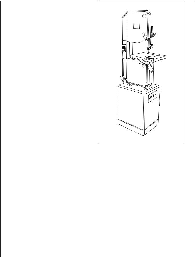
Introduction
This manual includes operating and maintenance instructions for the Wilton 14-Inch Tradesman Vertical Band Saws, Models 8201, 8203, 8201VS, and 8203VS. This manual also includes parts listings and illustrations of replaceable parts.
Band Saw Features
Refer to Figures 1 through 3 for key features of the band saw machine. Refer to the Specifications section for additional information on the features and capabilities of the saw.
Figure 1: Band Saw Features (Rear View) (Models 8201/8203)
Saw Head
Clutch Knob
Gearbox
Oil Level
Gauge Variable Speed
Control
Drive |
Pivoting |
|
Motor |
||
Motor |
||
Mounting |
||
|
||
|
Plate |
|
|
Motor Pulley |
Figure 2: Band Saw Features (Rear View) (Models 8201VS/8203VS)
Setup and Operation
Set-up
The band saw is shipped with the saw frame separated from the saw base. Set-up of the band saw involves installing the frame and setting-up the saw on the shop floor.
Assembly of Band Saw
The saw is shipped as two separate units — saw frame and base. The saw frame must, therefore, be assembled to the base.
1.Remove loose parts from the saw base and sawframe.
2.Place the base in the location in the shop and bolt the base to the floor. (See following section on spotting saw.) Put shims under the hold-down bolts as required to make sure the saw is level.
3.Place the saw frame on the base. Be sure the pulleys on the saw frame and pulleys in the base are aligned with each other.
4.Install the four bolts, upper washers, lower washers, lock washers and nuts that secure the frame to the base finger tight. Using a straight edge, align the pulleys. Then tighten the four attachment bolt and nuts.
5.Loosen the motor mounting bolts and install the drive belt(s).
Blade tension adjustment |
|
|
|
||
|
|
knob |
Upper drive |
7 |
|
|
|
|
|||
|
|
|
wheelUpper |
||
|
|
|
|
||
|
|
|
|
blade |
|
|
|
|
|
guide |
|
|
|
|
|
support |
|
|
|
|
|
assembly |
|
|
|
|
Lock Knob |
|
|
|
|
|
|
Upper blade |
|
|
|
|
|
guide and |
|
Upper |
|
|
|
support |
|
ON/OFF |
Optional rip |
Miter |
assembly |
|
|
wheel |
|
||||
guard |
switch |
fence |
slot |
Table |
|
Blade guard |
|
|
|
|
|
Lower wheel guard |
|
|
Lower drive |
|
|
Dust chute |
|
|
|
||
|
|
|
|
wheel |
|
|
|
|
|
Lower blade |
|
|
|
|
|
guide and |
|
|
|
|
|
support |
|
|
|
|
|
assembly |
|
|
|
|
|
Base |
|
Figure 3: Band Saw Features (Front View)
(All Models)
6.Tension the belts (refer to Changing Drive Belt Position).
7.Check gearbox fluid level in sight gauge. If required, add lubricant to bring level halfway up the sight gauge. (Two containers of Shell Spirax 90 HD gear oil are packed with the saw. The containers have sufficient amount of lubricant to fill the gearbox.)
8.Check blade tension and support mechanism adjustment (refer to Changing Saw Blades).
9.Plug the motor cable into the switch box on the saw frame. For 3-phase motors, follow the instructions in the Electrical section to complete the electrical hookup.
NOTE: Observe all electrical codes. Local codes or difficult environmental conditions may demand special electrical hook-ups. Always use a licensed electrician for any special electrical hook-up.
Setting-up Saw
The saw should be bolted securely to the shop floor to make sure the saw is stable when sawing long, heavy or unwieldy work pieces. Always use extra support for long or heavy stock.
There are lugs in the bottom of the saw base for use in bolting down of the saw. After positioning the saw, open the door in the base and mark the positions of the four lug holes. Move the saw to expose the marks. Prepare for attachment as required by the attachment method being used.
8 Install the applicalbe fasteners. Install shims as required to level the saw. Tighten the fastners to secure the saw to the floor.
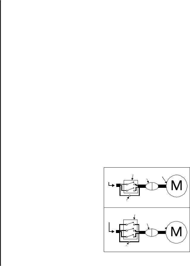
Electrical
Models 8201 and 8201VS are delivered with a 115 volt single phase motor. Models 8203 and 8203VS are delivered with a 220/440 volt, 3-phase motor.
When the saw is a 115 volt model, it is supplied with a standard 115 volt plug and power cord which can be plugged into any suitable branch circuit.
When the saw is equipped with a 3-phase motor there will be no plug on the 4-wire cable to the saw switch box. Instead, follow these instructions to connect the 3-phase motor to the power source:
Connecting to 3-phase power
1. Disconnect and lock out the branch circuit to
the saw before attempting electrical connections.
2.Connect the green or green-with-white-trace wire to the branch circuit ground wire.
3.Connect the remaining three wires to the power wires in the 3-phase branch circuit.
4.Reestablish power in the electrical branch.
5.Turn on power to the saw motor using the switch.
6.Observe the direction of the blade. It should be going DOWNWARD, into the slot on the table. If it is not going downward, the power wires are hooked-up incorrectly.
7.To correct hook-up, disconnect and lock out power to the branch, again. Reverse any two of the power wires on the hook-up to the saw cable.
8.Reestablish power in the branch and turn the saw on again. The blade should now be going downward into the table slot.
Note: local electrical codes or other codes may require direct connection to a covered, protected junction box, or other electrical hook-up method. Especially under difficult industrial conditions, specialized electrical connections may be necessary. For special electrical hook-ups, a licensed electrician should be used to connect the saw to power.
CAUTION: KNOW AND OBSERVE ALL LOCAL AND OTHER APPROPRIATE ELECTRICAL CODES WHEN ATTACHING THIS BAND SAW TO YOUR POWER SUPPLY.
1-ph. |
Switch |
Motor |
|
power |
Plug |
||
|
|||
source |
|
|
 Green or green with white trace
Ground lug
3-ph. |
Switch |
|
power |
|
Motor |
source |
Plug |
|
|
|
 Green or green
with white trace
Ground lug
Figure 4: Wiring Diagrams

Installing Optional Frame Riser
NOTE: Refer to the illustrations in the Replacement Parts section for location of the parts used on the frame riser.
1.Remove the saw blade (refer to Changing Saw Blades).
2.Remove the two screws at the top and bottom of the blade guide that holds the blade guide on the frame.
WARNING: The saw must be turned off and power disconnected any time the rubber protectors are being changed.
3.Unplug the electrical cord or open the circuit breaker in the branch circuit.
4.Support the upper frame and wheel assembly with a strap attached to an overhead crane. Use additional straps to be sure the frame assembly will be held in a stable position when it is lifted off the lower frame assembly.
5.Remove the nut on the bolt that clamps the upper frame to the lower frame and remove the bolt, two washers and nut.
6.Lift the upper frame high enough off of the lower frame to clear the riser casting.
7.Be certain the mating surfaces of the lower frame, riser, and upper frame are all clean and free from dirt and debris.
8.Position the riser casting over the lower frame. Make sure the locating dowels are inserted in the mating holes in the riser casting.
9.Lower the upper frame onto the riser casting. Make sure the locating dowels fit into their mating holes.
10.Put the new (longer) attaching bolt and top washer through the upper frame and riser, into the lower frame.
11.Put a washer and nut on the bolt and tighten securely.
12.Attach the bracket hooks to the top and bottom of the blade guard using self-tapping screws.
13.Attach the blade guide using the screws that held the original (shorter) guard.
14.Remove the old (shorter) blade guide post assembly from the upper frame.
15.The guide support assembly with the carbide guides and blade support bearings should be transferred to the new, longer support rod.
Several other new parts are included for this component. (Refer to the parts illustrations for more detail.)
16.Install a new 105-inch blade (refer to Changing a Blade). Make sure blade tension and tracking
are checked and adjusted as required.
18.Install the extension plug cable between the motor plug and switch plug.
19.Plug the electrical cord into the power source or close the circuit breaker on the branch circuit. Operate the band saw to verify blade tracking.
Installing Optional Rip Fence
The rip fence slides on two rails attached at the front and rear of the work table. Install the fence mechanism as follows:
NOTE: Refer to the illustrations in the Replacement Parts section for location of the parts used on the rip fence.
1.Slide the rails into the fence.
2.Ease the fence and rails into position on the table.
3.Using the four spacers and four attachment bolts, attach the rails securely to the saw table.
4.The fence can now be adjusted and used according the instructions in Adjustment and Use of Optional Rip Fence.
9

Operating Instructions
Operating Controls
START/STOP Switch
The START/STOP switch (refer to Figure 5) is used to turn on the band saw drive motor. The START switch has a molded guard which prevent inadvertent pressing of the START pushbutton.
START/STOP Switch
Guarded START
Switch
E-Stop
Figure 5. START/STOP Controls
The STOP pushbutton is not guarded to allow use as an E-stop in an emergency.
Variable Speed Control
The variable speed control (refer to Figure 9) is used to change the speed of the saw blade. Refer to Adjusting Blade Speed for additional information on the use of the variable speed control.
10
Operating Instructions
Saw blades
The Wilton 14-inch saws accept blades from 1/8- inch wide to 3/4-inch wide. The narrower widths are used for cutting shapes or circles; the wider widths are used for straight cuts.
For straight cuts, use the widest available saw blade. A wide blade provides cutting stability, and allows for more accurate and straighter cuts. Blade speed effects the efficiency of the cut and the service life of the blade. Good shop practice requires that work-hardening materials, such as stainless steel, require the cut be completed in a single pass. Otherwise, the effect of stopping the cut can result in hardening of the cut interface.
Other materials such as wood require higher blade speeds to prevent fiber tearing. The chart in
Figure 6 provides suggested blade speeds for various
types of materials. The recommended speeds should be decreased 30 to 50% when using carbon steel blades. (The chart provides speeds that are based on cutting a 4-inch thick work piece using a bi-metal blade without cutting fluid.)
The following conditions should also be considered:
1.Increase speed 15% for materials 1/4-inch thick, 12% for 3/4-inch thick, 10% for 1 1/4- inch thick, and 5% for 2 1/2-inch thick.
2.Decrease speed 12% when cutting 8-inch thick material.
To avoid tooth breakage, select a blade-tooth pitch that will have two or more teeth in contact with the workpiece at all times.
Different blade materials and tooth geometry (pitch and set) permit sawing a wide range of common and exotic materials. Contact your industrial distributor for recommendations on specialized blades. Using the corrrect blade can save you time, trouble, and the possibility of dulling and pemature discarding of the blade you normally might use. NOTE: Always use a sharp blade. SHARP BLADES ARE CHEAP INSURANCE AGAINST POOR CUTTING EFFICIENCY AND ACCELERATED MACHINE WEAR.
Material being cut |
Speed (SF/M) range |
Structural steel shapes |
165 |
Low carbon steel |
160-165 |
Medium carbon steel |
115 |
High carbon steel |
90-100 |
Cr-moly steel |
105-135 |
Ni-Cr-moly steel |
90-115 |
Chromium steel |
80-140 |
Cr-vanadium steel |
105-115 |
Tool steel |
40-80 |
Stainless steel |
40-70 |
Free machining steel |
80-100 |
Cast iron |
55-90 |
Copper alloy (CU-Zm) |
55 |
Bronze |
90 |
Al-bronze |
40 |
Monel |
40-45 |
Titanium alloy |
25-40 |
Aluminum (soft) |
3000 |
Aluminum (T-6+) |
3000 |
Carbon |
3000 |
Slate |
80-160 |
PTFE sheet, rod, rounds |
3000 |
Hard rubber |
3000 |
Plywood |
3000 |
Other woods |
3000 |
Figure 6. Blade Speed to Material Chart
 Loading...