


 Loading...
This Manual is Bookmarked
Operating Instructions — Parts Manual
7 x 12 Cut-off Band Saw
Models: 3400/3410
WHM TOOL GROUP, Inc. |
177339 |
|
|
2420 Vantage Drive |
|
Elgin, Illinois 60124 |
Part No. 9078201 |
Ph.: 800-274-6848 |
Revision B 05/07 |
www.wmhtoolgroup.com |
Copyright © 2007 WMH Tool Group |

Warranty and Service
WMH Tool Group, Inc., warrants every product it sells. If one of our tools needs service or repair, one of our Authorized Service Centers located throughout the United States can give you quick service. In most cases, any of these WMH Tool Group Authorized Service Centers can authorize warranty repair, assist you in obtaining parts, or perform routine maintenance and major repair on your
WILTON® tools. For the name of an Authorized Service Center in your area call 1-800-274-6848.
MORE INFORMATION
Group distributor, or visit wiltontool.com.
WARRANTY
WILTON products carry a limited warranty which varies in duration based upon the product. (MW = Metalworking)
WHAT IS COVERED?
This warranty covers any defects in workmanship or materials subject to the exceptions stated below. Cutting tools, abrasives and other consumables are excluded from warranty coverage.
WHO IS COVERED?
This warranty covers only the initial purchaser of the product.
WHAT IS THE PERIOD OF COVERAGE?
The general WILTON warranty lasts for the time period specified in the product literature of each product.
WHAT IS NOT COVERED?
This warranty does not cover defects due directly or indirectly to misuse, abuse, negligence or accidents, normal wear-and-tear, improper repair or alterations, or lack of maintenance.
HOW TO GET SERVICE
The product or part must be returned for examination, postage prepaid, to a location designated by us. For the name of the location nearest you, please call 1-800-274-6848.
You must provide proof of initial purchase date and an explanation of the complaint must accompany the merchandise. If our inspection discloses a defect, we will repair or replace the product, or refund the purchase price, at our option.
We will return the repaired product or replacement at our expense unless it is determined by us that there is no defect, or that the defect resulted from causes not within the scope of our warranty in which case we will, at your direction, dispose of or return the product. In the event you choose to have the product returned, you will be responsible for the handling and shipping costs of the return.
HOW STATE LAW APPLIES
This warranty gives you specific legal rights; you may also have other rights which vary from state to state.
LIMITATIONS ON THIS WARRANTY
WMH TOOL GROUP LIMITSALL IMPLIED WARRANTIES TO THE PERIOD OF THE LIMITED WARRANTY FOR EACH PRODUCT. EXCEPTAS STATED HEREIN, ANY IMPLIED WARRANTIES OR MERCHANTABILITYAND FITNESS ARE EXCLUDED. SOME STATES DO NOTALLOW
LIMITATIONS ON HOW LONG THE IMPLIED WARRANTY LASTS, SO THE ABOVE LIMITATION MAY NOTAPPLY TO YOU.
WMH TOOL GROUP SHALL IN NO EVENT BE LIABLE FOR DEATH, INJURIES TO PERSONS OR PROPERTY, OR FOR INCIDENTAL,
CONTINGENT, SPECIAL, OR CONSEQUENTIAL DAMAGES ARISING FROM THE USE OF OUR PRODUCTS. SOME STATES DO NOT ALLOW THE EXCLUSION OR LIMITATION OF INCIDENTAL OR CONSEQUENTIAL DAMAGES, SO THEABOVE LIMITATION OR EXCLUSION MAY NOT APPLY TO YOU.
WMH Tool Group sells through distributors only. The specifications in WMH catalogs are given as general information and are not binding. Members of WMH Tool Group reserve the right to effect at any time, without prior notice, those alterations to parts, fittings, and accessory equipment which they may deem necessary for any reason whatsoever.
Table of Contents |
|
|
|
|
|
Cover Page .......................................................................................................................... |
1 |
|
Warranty................................................................................................................................ |
2 |
|
Table of Contents .................................................................................................................. |
3 |
|
General Specifications .......................................................................................................... |
4 |
|
Warnings ............................................................................................................................ |
5-6 |
|
Using the Vise.................................................................................................................... |
7-9 |
|
Setting Blade Guides ............................................................................................................ |
9 |
|
Hydraulic Feed Control........................................................................................................ |
10 |
|
Using Stock Stop................................................................................................................. |
10 |
|
Changing Blade Speeds ..................................................................................................... |
11 |
|
Blade Selection................................................................................................................... |
11 |
|
Evaluating Cutting Eficiency ................................................................................................ |
11 |
|
Blade Break-in Procedures ................................................................................................. |
11 |
|
Starting a Cut ...................................................................................................................... |
11 |
|
Angle Cuts ..................................................................................................................... |
12-13 |
|
Replacing Blades ................................................................................................................ |
14 |
|
Adjusting Blade Tracking ..................................................................................................... |
14 |
|
Blade Alignment Adjustments .............................................................................................. |
15 |
|
When to Adjust Blade Guides .............................................................................................. |
15 |
|
Replacing Blade Guides and Support Components............................................................. |
16 |
|
Adjust Blade for Parallelism ................................................................................................ |
16 |
|
Adjusting Blade Vertical ...................................................................................................... |
17 |
|
Test Cutting to Verify Adjustment Accuracy ........................................................................... |
17 |
|
Adjusting Guide Bearings.................................................................................................... |
18 |
|
Replacing Guide Bearings .................................................................................................. |
18 |
|
Adjusting Blade Back Up Bearing ....................................................................................... |
18 |
|
Replacing the Drive Wheel .................................................................................................. |
19 |
|
Installing the Vertical Sawing Table ...................................................................................... |
19 |
|
Replacing Idler Wheel or Bearings ...................................................................................... |
19 |
3 |
Servicing the Hydraulic Control Cylinder .............................................................................. |
20 |
|
Machine Set-up ................................................................................................................... |
21 |
|
Uncrating and Spotting the Saw........................................................................................... |
21 |
|
Electrical ............................................................................................................................. |
21 |
|
Changing Operating Voltage ............................................................................................... |
21 |
|
Installing the Coolant Kit ...................................................................................................... |
22 |
|
Chip Brush Replacement .................................................................................................... |
22 |
|
Adjusting Horizontal Stop and Motor Switch ......................................................................... |
22 |
|
To Replace or Adjust the Horizontal Stop ............................................................................. |
22 |
|
Adjusting the Motor Switch Actuator..................................................................................... |
22 |
|
Troubleshooting.............................................................................................................. |
23-24 |
|
Replacement Parts and Breakdowns ............................................................................. |
25-30 |
|
|
|
|
General
Specifications
|
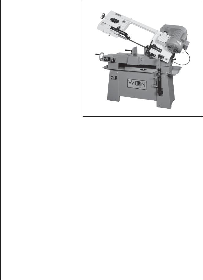
The Wilton Models 3400 and 3410 cut-off band saws |
The Model 3410 is equipped with an optional coolant |
||
|
are designed for high production cut-off work. Four cutting |
system which can greatly extend blade life and speed the cut- |
||
|
speeds and a hydraulic feed control allows the efficient cut- |
ting of a variety of materials which are best cut with cutting |
||
|
ting of virtually any material. |
|
fluids and coolants. |
|
|
A removable table also allows the saw to function as a |
The Model 3400 is not equipped with a coolant system. |
||
|
vertical band saw. |
|
However, the coolant system is available as an add-on kit for |
|
|
|
|
customer installation. |
|
|
Specifications: |
|
|
|
|
|
|
||
|
Cutting capacity |
7 in. (178mm) round bar stock or tubing |
||
|
|
9 1/2 in. wide x 7 in. high (240 x 178mm) rectangular stock |
||
|
|
12 in. wide x 1 in. high (305 x 25.4mm) flat stock |
||
4 |
Blade speeds |
3 3/4 in. wide x 6 in. high (95.3 x 150mm) at 45 degree angle |
||
80, 130, 180 and 265 SFM -- belt selectable |
||||
|
||||
|
Blade drive |
Heat treated steel worm pinion driving a bronze |
||
|
|
worm ring gear in an oil bath |
||
|
Motor |
3/4 HP, 1725 RPM, 115/230V, single phase, capacitor start |
||
|
Blade guides |
Side: Eccentric shaft with sealed ball bearings |
||
|
|
Rear: Sealed ball bearing |
||
|
Blade size |
3/4 x .032 x 93 in. |
|
|
|
Blade wheels |
11 7/16 in. (280.56mm) diameter flanged cast iron |
||
|
Dimensions (LWH) |
50 x 18 x 41 in. (1270 x 457 x 1041mm) in lowered position |
||
|
Weight |
275 lbs. (125kg) |
|
|
|
Wet cutting package |
1 gallon (4.4L) capacity tank with 3GPM (13L/M) pump -- Optional wet kit |
||
|
|
Part No. 5635500 includes tank with baffle, pump 120V/240V, hoses, |
||
|
|
flexible nozzle, shut-off valve and required electrics. This kit is delivered |
||
|
Vertical saw operation |
installed on Model 3410 saws. |
||
|
9 1/2 x 10 in. (241 x 254mm) |
|||
|
Table size (LW) |
|||

|
|
|
|
|
|
|
|
|
- Misuse of this machine can cause serious injury. |
- Always shut off the machine when not in use. |
|
- For safety, machine must be set up, used and serviced |
When servicing machine: |
|
properly. |
- Always unplug machine from electrical power while |
|
- Read, understand and follow instructions in the |
servicing. |
|
operator’s and parts manual which was shipped with |
- Always follow instructions in operators and parts |
|
your machine. |
manual when changing accessory tools or parts. |
|
When setting up machine: |
- Never modify the machine without consulting Wilton |
|
- Always avoid using machine in damp or poorly lighted |
Corporation. |
|
work areas. |
You — the stationary power tool user — hold the |
|
- Always be sure machine is securely anchored to the |
key to safety. |
|
floor. |
Read and follow these simple rules for best |
|
- Always keep machine guards in place. |
results and full benefits from your machine. Used |
|
- Always put start switch in OFF“ position before |
properly, Wilton’s machinery is among the best in |
|
plugging in machine. |
design and safety. However, any machine used |
|
When using machine: |
improperly can be rendered inefficient and unsafe. It is |
|
- Never operate with machine guards missing. |
absolutely mandatory that those who use our products |
|
- Always wear safety glasses with side shields (See |
be properly trained in how to use them correctly. They |
|
ANSI Z87.1) |
should read and understand the Operators and Parts |
|
- Never wear loose clothing or jewelry. |
Manual as well as all labels affixed to the machine. |
|
- Never overreach — you may slip and fall into the |
Failure in following all of these warnings can cause |
|
machine. |
serious injuries. |
|
- Never leave machine running while away from it. |
|
|
Machinery general safety warnings
1. Always wear protective eye wear when operating |
9. Maintain all machine tools with care. Follow all |
|
|
machinery. Eye wear shall be impact resistant, protective |
maintenance instructions for lubricating and the changing |
|
|
safety glasses with side shields which comply with ANSI |
of accessories. No attempt shall be made to modify or |
|
|
Z87.1 specifications. Use of eye wear which does not |
have makeshift repairs done to the machine. This not |
|
|
comply with ANSI Z87.1 specifications could result in |
only voids the warranty but also renders the machine |
|
|
severe injury from breakage of eye protection. |
unsafe. |
|
|
2. Wear proper apparel. No loose clothing or |
10. |
Machinery must be anchored to the floor. |
|
jewelry which can get caught in moving parts. Rubber |
11. Secure work. Use clamps or a vise to hold work, |
5 |
|
soled footwear is recommended for best footing. |
when practical. It is safer than using your hands and it |
||
3. Do not overreach. Failure to maintain proper |
frees both hands to operate the machine. |
|
|
working position can cause you to fall into the machine or |
12. |
Never brush away chips while the machine is in |
|
cause your clothing to get caught — pulling you into the |
operation. |
|
|
machine. |
13. |
Keep work area clean. Cluttered areas invite |
|
4. Keep guards in place and in proper working |
accidents. |
|
|
order. Do not operate the machine with guards removed. |
14. |
Remove adjusting keys and wrenches before |
|
5. Avoid dangerous working environments. Do not |
turning machine on. |
|
|
use stationary machine tools in wet or damp locations. |
15. |
Use the right tool. Don't force a tool or attach- |
|
Keep work areas clean and well lit. Special electrics |
ment to do a job it was not designed for. |
|
|
should be used when working on flammable materials. |
16. |
Use only recommended accessories and follow |
|
6. Avoid accidental starts by being sure the start |
manufacturers instructions pertaining to them. |
|
|
switch is OFF” before plugging in the machine. |
17. |
Keep hands in sight and clear of all moving |
|
7. Never leave the machine running while unat- |
parts and cutting surfaces. |
|
|
tended. Machine shall be shut off whenever it is not in |
18. |
All visitors should be kept at a safe distance |
|
operation. |
from the work area. Make workshop completely safe by |
|
|
8. Disconnect electrical power before servicing. |
using padlocks, master switches, or by removing starter |
|
|
Whenever changing accessories or general maintenance |
keys. |
|
|
is done on the machine, electrical power to the machine |
19. |
Know the tool you are using — its application, |
|
must be disconnected before work is done. |
limitations, and potential hazards. |
|
|

20.Some dust created by power sanding, sawing, |
General Electrical Cautions |
grinding, drilling and other construction activities |
This saw should be grounded in accordance with |
contains chemicals known to cause cancer, birth |
the National Electrical Code and local codes and |
defects or other reproductive harm. Some examples of |
ordinances. This work should be done by a qualified |
these chemicals are: |
electrician. The saw should be grounded to protect the |
Lead from lead based paint |
user from electrical shock. |
|
crystalline silica from bricks and cement and other |
Wire sizes |
|
masonry products, and |
Caution: for circuits which are far away from the |
|
arsenic and chromium from chemically-treated |
electrical service box, the wire size must be increased |
|
in order to deliver ample voltage to the motor. To |
||
lumber. |
||
minimize power losses and to prevent motor overheat- |
||
|
||
21.Your risk from those exposures varies, depend- |
ing and burnout, the use of wire sizes for branch |
|
circuits or electrical extension cords according to the |
||
ing on how often you do this type of work. To reduce your |
||
following table is recommended: |
||
exposure to these chemicals: work in a well ventilated |
||
|
||
area, and work with approved safety equipment, such as |
|
|
those dust masks that are specifically designed to filter |
|
|
out microscopic particles. |
|
Conductor length |
AWG (American wire gauge) number |
|
|
240 volt lines |
120 volt lines |
0-50 feet |
No. 14 |
No. 14 |
50-100 feet |
No. 14 |
No. 12 |
Over 100 feet |
No. 12 |
No. 8 |
|
|
|
|
Safety instructions on sawing systems |
|||
|
1. Always wear leather gloves when handling |
close as possible to the work piece. |
||
|
saw blade. The operator shall not wear gloves when |
|||
|
9. Always wear protective eye wear when |
|||
|
operating the machine. |
|||
|
operating, servicing or adjusting machinery. Eyewear |
|||
|
2. All doors shall be closed, all panels replaced, |
|||
|
shall be impact resistant, protective safety glasses with |
|||
|
and all other safety guards in place prior to the machine |
|||
|
side shields complying with ANSI Z87.1 specifications. |
|||
|
being started or operated. |
|||
|
Use of eye wear which does not comply with ANSI |
|||
|
3. Be sure that the blade is not in contact with the |
|||
|
Z87.1 specifications could result in severe injury from |
|||
|
workpiece when the motor is started. The motor shall |
|||
|
breakage of eye protection. See figure B. |
|||
|
be started and you should allow the saw to come to full |
|||
|
10. Non-slip footwear and safety shoes are |
|||
|
speed before bringing the workpiece into the saw blade. |
|||
|
recommended. See figure C. |
|||
|
4. |
Keep hands away from the blade area. See |
||
|
11. Wear ear protectors (plugs or muffs) during |
|||
6 |
figure A. |
|
extended periods of operation. See figure D. |
|
5. |
Remove any cut off piece carefully while |
|||
12. The workpiece, or part being sawed, must be |
||||
|
keeping your hands free of the blade area. |
securely clamped before the saw blade enters it. |
||
|
6. Saw must be stopped and electrical supply |
|||
|
13. Remove cut off pieces carefully, keeping |
|||
|
must be cut off before any blade replacement or |
|||
|
hands away from sawblade. |
|||
|
adjustment of blade support mechanism is done, or |
|||
|
14. Saw must be stopped and electrical supply |
|||
|
before any attempt is made to change the drive belts or |
|||
|
cut off or machine unplugged before reaching into |
|||
|
before any periodic service or maintenance is per- |
|||
|
cutting area. |
|||
|
formed on the saw. |
|||
|
15. Avoid contact with coolant, especially |
|||
|
7. Remove all loose items and any unnecessary |
|||
|
guarding your eyes. |
|||
|
work pieces from the area before starting machine. |
|||
|
|
|||
|
8. Bring adjustable saw guides and guards as |
|
||
A |
B |
C |
D |

Operating Instructions
Using the vise
The vise on the saw table has two jaws. The jaw closest to the right hand side of the table is the stationary jaw. This jaw is firmly secured to the table using its pivot and lock bolts. When making a straight cut the stationary jaw is at right angles to the saw blade. When making an angle cut, the stationary jaw is first loosened, then adjusted to the desired angle, then secured to the table, again.
Figure 1: Vise jaw nomenclature
Locking vise jaw
The locking jaw is an assembly which includes the lead screw nut which encases the lead screw, the lead screw shaft (which screws into the lead screw nut,) the thrust shaft, spring, and quick release handle.
The thrust shaft moves up or down when the quick release handle moves up or down.
The thrust shaft has a nut under the quick release handle which adjusts the clamping pressure between the adjustable jaw and the table, itself. When this nut is too tight, the adjustable jaw cannot pivot. When this nut is too loose, the jaw can pivot, and also tilt upward. Therefore, this nut should be slightly loose. This will allow the jaw to pivot an conform to any angle at which the stationary jaw is set.
However, you should guard against excessive loosening of this nut. If too loose, the jaw can tilt when it contacts the workpiece and full clamping pressure cannot be effectively applied to the workpiece.
If the shaft is too tight to allow pivoting of the jaw, loosen the shaft slightly by turning the nut under the quick release handle counterclockwise. If the jaw tilts exces-
The jaw closest to the left hand side of the table is the locking jaw. This jaw clamps the workpiece against the stationary jaw to hold it securely for cutting. The locking jaw can pivot to conform to the angle of the work piece which is held in the stationary jaw.
Before cutting can begin, the vise must be properly set and positioned. The procedures are different for right angle cutting and for angle cutting. Setting procedures are given in the following sections.
sively, use the nut under the quick release handle to
tighten the shaft slightly so the jaw slides easily, but flat 7 against the saw table.
The locking vise jaw is tightened or loosened against the workpiece being cut by using the lead screw handle. The handle is attached to a lead screw underneath the saw table. The lead screw has a series of grooves on its length. These grooves capture a thrust shaft on the lower side of the locking jaw. As the lead screw handle is turned, the grooves move to the left or right, and therefore the locking jaw is moved to the left or right to open or close the jaw against any workpiece on the table.
The thrust shaft on the locking vise jaw is a component part of the quick release handle on top of the locking jaw. This quick release handle is spring loaded to force the handle (and, therefore, the thrust shaft) downward.
When you pull up on the quick release handle, the thrust shaft is removed from its groove. This allows you to slide the jaw to a new position on the table. Releasing the handle pushes the thrust shaft against the lead screw shaft. When the lead screw handle is turned, a groove will
eventually catch the thrust shaft and allow you to open or close the locking jaw at its new lead screw position.
When you slide the jaw to a new position, you can see where the nearest lead screw groove is by looking through the slot above the lead screw. (See Figure 1.)
Changing the locking jaw location:
1.Lift the quick release handle.
2.Slide the jaw until it contacts the workpiece.
3.Turn the lead screw handle until the thrust shaft drops into a groove.
4.Further turning of the lead screw handle will either clamp or release the workpiece in the vise. Turn clockwise to increase clamping pressure. Turn counterclockwise to release clamping pressure.
Stationary vise jaw
The stationary vise jaw pivots on the pivot bolt, Figure 1, and is locked at any required angle by the lock bolt.
There are two different table positions for the stationary vise jaw. One position is used for right angle cuts ("straight" cutting) and the other position is used for cutting of all other angles. Moving the vise from one position to the other requires unbolting and re-bolting the jaw to the saw table.
Four tapped holes in the saw table allow a change of pivot and lock bolt position. The holes in the right-most position closest to the motor are used for right angle cutting. The holes in the left-most position are used for all angle cutting.
8Changing the stationary vise jaw position:
1.Remove the pivot and lock bolts.
2.Slide the stationary jaw to the required position on the table.
3.Re-insert the pivot and lock bolts.
4.Adjust stationary jaw angle according to requirements for straight or angle cuts, then tighten both bolts securely.
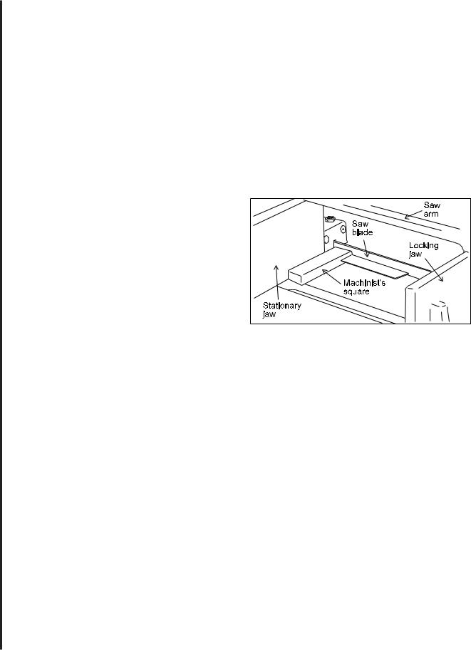
Adjusting stationary jaw: straight cuts
For accurate right angle or "straight" cutting, adjust the vise as follows:
1.Disconnect the saw from its electrical power source to prevent accidental start-ups.
2.With the saw arm and blade in horizontal position, place a machinist's square against the blade and stationary vise jaw. (See Figure 2.)
3.If the vise jaw is not square to the blade, loosen both the pivot and lock bolts shown in Figure 1, and adjust the jaw until it is square.
4.Tighten the pivot and lock bolts.
5.Reconnect electrical power to the saw.
Figure 2: Setting the stationary jaw at right angles to the saw blade.
Adjusting stationary jaw: angle cuts
The angle of the stationary vise jaw with respect to the saw blade is what determines the cut angle on the workpiece. The stationary jaw can be adjusted to any angle between 0 degrees (right angle to the blade) and 45 degrees.
In order to cut angles, however, it will be necessary for you to move the stationary vise jaw to its left-most set of attachment holes as described in the following sections.
After placing the jaw in the angle cutting position, you can adjust to the desired cutting angle using one of the two following methods.
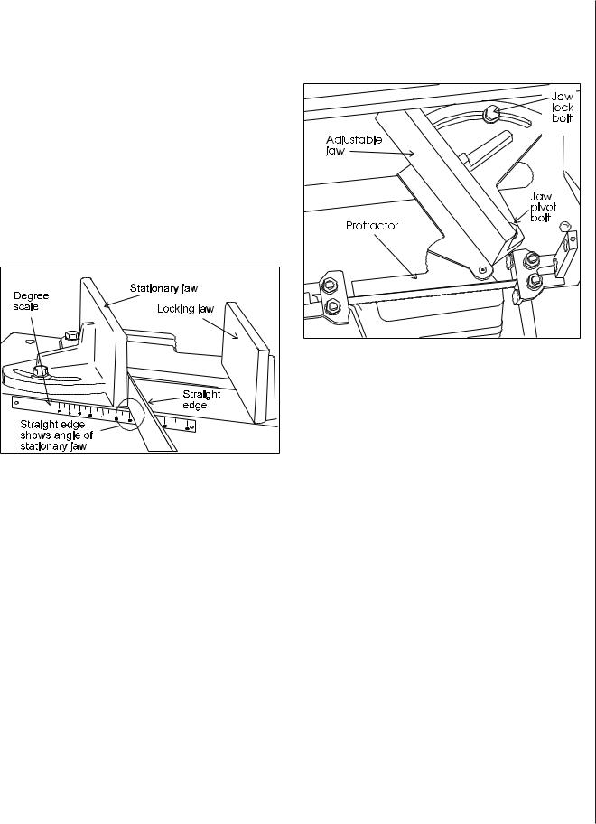
Adjusting angles with the scale on the saw table
There is a scale on the rear of the saw base which can be used to establish the angle of cut.
1.Raise the saw arm to full height and lock it in position with the quick shut-off valve.
2.Slide the locking jaw to full open position.
3.Loosen the pivot and lock bolts shown in Figure 1.
4.Lay a straight edge on the saw frame so it contacts the stationary vise jaw. (See Figure 3.)
5.Turn the vise jaw until the straight edge is above the angle of cut you require as shown on the angle gauge.
6.Tighten both the pivot and lock bolts.
7.Remove the straight edge and proceed to cut as described in Angle sawing.
Figure 3: Using table scale to set jaw for angle cuts
Adjusting stationary jaw for high accuracy angle cutting:
1.Raise the saw arm to full height and lock it in position with the shut-off valve.
2.Open the vise to full width.
3.Loosen the pivot and lock bolts shown in Figure 1.
4.Open the shut-off valve and lower the saw arm until it is at full horizontal position.
5.Take a machinist's protractor and set it to the angle you need to cut.
6.Lay the protractor on the saw table and place one edge of the protractor against the saw blade and the other edge against the stationary vise jaw. (Figure 4.)
7.Adjust the stationary vise jaw until its angle is correct with respect to the blade, then lock the stationary jaw firmly using the pivot and lock bolts.
The saw is now accurately set to the exact angle you have set on the machinist's protractor. You can now saw the workpieces according to instructions on Angle sawing.
Figure 4: Using a protractor to set jaw angle
Setting the blade guides
To produce accurate cuts the distance between the blade guide/supports must be set correctly. Whenever possible, set the blade guide assembly so it clears the workpiece by approximately 1/8 inch on either side of the workpiece.
The guides may be moved by loosening the lock handles which secure the bracket bars to the saw arm.
There is, however, a limit to how close the guide can 9 be set with respect to the table. When set too close to the blade clearance slot, the guide bearings can hit the table casting and prevent the arm from moving to full horizontal. When this happens, the saw cannot complete its cut.
This won't be a problem with the right-hand guide. On the other hand, the left-hand guide typically cannot be much closer to the right-hand guide than 6 inches or so. Therefore, when cutting smaller section material, be sure the blade is correctly adjusted, tensioned properly, sharp, and appropriate to the type of material being cut.
Loading...