


Operating Instructions & Parts Manual
10-Inch x 16-Inch Horizontal
Cut-Off Band Saw
Models 7020/7040
Part No. 9078341
Revision C4 07/03
WMH TOOL GROUP 2420 Vantage Drive Elgin, IL 601237 TEL: 1-888-594-5866 FAX: 1-800-626-9676
www.wmhtoolgroup.com
Table of Contents |
|
|
|
|
|
General Specifications ....................................................................................................................................... |
5 |
|
Specifications .................................................................................................................................................... |
5 |
|
General Specifications ....................................................................................................................................... |
5 |
|
Machinery General Safety Warnings ................................................................................................................. |
6 |
|
Operating Precautions ....................................................................................................................................... |
6 |
|
General Electrical Cautions ................................................................................................................................ |
7 |
|
Safety Instructions on Sawing Systems ............................................................................................................. |
7 |
|
Introduction...................................................................................................................................................... |
8 |
|
Operating Instructions .................................................................................................................................... |
8 |
|
Controls ............................................................................................................................................................. |
8 |
|
Setting Blade Speed ........................................................................................................................................... |
8 |
|
Operating Instructions ........................................................................................................................................ |
8 |
|
Raising/Lowering the Saw Head ......................................................................................................................... |
9 |
|
Controlling the Cut: Hydraulic Feed Control ...................................................................................................... |
9 |
|
Evaluating Cutting Efficiency ............................................................................................................................. |
9 |
|
Blade Selection .................................................................................................................................................. |
9 |
|
Blade Break-in Procedures .............................................................................................................................. |
10 |
|
Work Setup .................................................................................................................................................... |
10 |
|
Securing the Workpiece for Square Cuts ........................................................................................................ |
10 |
|
Adjusting the Vise for Angle Cuts ..................................................................................................................... |
10 |
|
Work Set-up .................................................................................................................................................... |
10 |
|
Installation and Adjustment of Work Stop .......................................................................................................... |
11 |
|
Starting the Saw ............................................................................................................................................... |
11 |
|
Adjustments ................................................................................................................................................... |
12 |
|
Blade Tracking Adjustment ............................................................................................................................... |
12 |
|
Coolant Flow .................................................................................................................................................... |
12 |
|
Coolant Mixture and Quantity ........................................................................................................................... |
12 |
|
Factory or Field Procedure .............................................................................................................................. |
12 |
|
Adjustments ..................................................................................................................................................... |
12 |
|
Blade Guide Bearing Adjustment ...................................................................................................................... |
13 |
|
Test Cutting to Verify Adjustment Accuracy ...................................................................................................... |
14 |
|
Adjustment of the Limit Switch .......................................................................................................................... |
14 |
|
Maintenance ................................................................................................................................................... |
14 |
|
Cleaning .......................................................................................................................................................... |
14 |
|
Lubrication ....................................................................................................................................................... |
14 |
|
Maintenance .................................................................................................................................................... |
14 |
3 |
Changing Blades .............................................................................................................................................. |
15 |
|
Changing the Drive Belt ................................................................................................................................... |
15 |
|
Replacing the Drive Motor ................................................................................................................................ |
15 |
|
Adjusting the Counterbalance Spring ............................................................................................................... |
15 |
|
Replacing the Drive Wheel ............................................................................................................................... |
16 |
|
Adjusting the Blade Guides .............................................................................................................................. |
16 |
|
Replacement of Carbide Blade Guide .............................................................................................................. |
16 |
|
Replacement of Guide Bearings ....................................................................................................................... |
17 |
|
Replacement of Blade Edge Bearings .............................................................................................................. |
17 |
|
Replacement of the Wire Brush ....................................................................................................................... |
17 |
|
Machine Setup ............................................................................................................................................... |
17 |
|
Uncrating and Spotting ..................................................................................................................................... |
17 |
|
Electrical .......................................................................................................................................................... |
18 |
|
Wiring Diagrams .............................................................................................................................................. |
18 |
|
Troubleshooting ............................................................................................................................................. |
20 |
|
|
|
|

Table of Contents
Replacement Parts ........................................................................................................................................ |
21 |
Parts List - Base .............................................................................................................................................. |
23 |
Parts List - Head .............................................................................................................................................. |
27 |
4
General Specifications
The Wilton Models 7020/7040 Horizontal Cut-Off |
an oil bath, transmits smooth and positivepower to the |
Bandsaws are ruggedly built, precision machines de- |
blade. This drive system coupled with the recirculating |
signed for either wet or dry applications. The 2 HP |
coolant system keeps the blade running cool and true, |
motor along with the worm gear reduction drive train in |
which results in longer blade life. |
Specifications |
|
|
|
|
|
|
|
Capacity |
|
10" Round |
|
|
|
10" x 10" Square |
|
|
|
9" x 16" Rectangle |
|
|
|
|
|
Speeds |
|
100 to 350 feet per minute - variable speed |
|
|
|
|
|
Motor |
|
Model 7020 - 1.5 H.P., 1 phase, 110/220V |
5 |
|
|
Model 7040 - 2 H.P., 3 phase, 220/440V |
|
|
|
|
|
Blade Size |
|
1" x .035" x 135" |
|
|
|
|
|
Blade Guides |
|
Adjustable 6 point contact combination bearing and carbide |
|
|
|
|
|
Blade Wheels |
|
14" diameter, cast iron |
|
|
|
|
|
Dimensions |
|
Length: 79" / Width: 31" / Height: 41" |
|
|
|
|
|
Shipping Weight |
|
Approximately 725 pounds |
|
|
|
|
|
Vise |
|
Rapid acting, 3 jaw design |
|
|
|
|
|
Coolant System |
|
Recirculating system standard with each machine complete with 1 GPM pump, 8 |
|
|
|
gallon reservoir, and coolant applied through the blade guides. |
|
|
|
|
|

|
|
|
|
|
|
|
|
|
- Misuse of this machine can cause serious injury. |
- Always follow instructions in Operating Instruc- |
|
- For safety, machine must be set up, used and |
tions and Parts Manual when changing acces- |
|
serviced properly. |
sory tools or parts. |
|
- Read, understand and follow instructions in the |
- Never modify the machine without consulting |
|
Operating Instructions and Parts Manual which |
Wilton Corporation. |
|
was shipped with your machine. |
You - the Stationary Power Tool User - Hold |
|
When Setting up Machine: |
the Key to Safety. |
|
- Always avoid using machine in damp or poorly |
Read and follow these simple rules for best results |
|
lighted work areas. |
and full benefits from your machine. Used properly, |
|
- Always be sure the machine support is se- |
Wilton’s machinery is among the best in design and |
|
curely anchored to the floor or the work bench. |
safety. However, any machine used improperly can |
|
When Using Machine: |
be rendered inefficient and unsafe. It is absolutely |
|
- Always wear safety glasses with side shields |
mandatory that those who use our products be |
|
(See ANSI Z87.1) |
properly trained in how to use them correctly. They |
|
- Never wear loose clothing or jewelry. |
should read and understand the Operating Instruc- |
|
- Never overreach - you may slip and fall. |
tions and Parts Manual as well as all labels affixed to |
|
When Servicing Machine: |
the machine. Failure in following all of these warn- |
|
- Always disconnect the machine from its electri- |
ings can cause serious injuries. |
|
cal supply while servicing. |
|
|
Machinery General Safety Warnings |
||
1. |
Always wear protective eye wear when |
is done. |
|
operating machinery. Eye wear shall be impact |
9. Maintain all machine tools with care. Follow all |
|
resistant, protective safety glasses with side shields |
maintenance instructions for lubricating and the |
|
which comply with ANSI Z87.1 specifications. Use |
changing of accessories. No attempt shall be made |
|
of eye wear which does not comply with ANSI |
to modify or have makeshift repairs done to the |
|
Z87.1specifications could result in severe injury |
machine. This not only voids the warranty but also |
|
from breakage of eye protection. |
renders the machine unsafe. |
2. |
Wear proper apparel. No loose clothing or jewelry |
10. Machinery must be anchored to the floor. |
|
which can get caught in moving parts. Rubber soled |
11. Secure work. Use clamps or a vise to hold work, |
|
footwear is recommended for best footing. |
when practical. It is safer than using your hands |
3. |
Do not overreach. Failure to maintain proper work- |
and it frees both hands to operate the machine. |
6 |
ing position can cause you to fall into the machine |
12. Never brush away chips while the machine is in |
or cause your clothing to get caught pullingyou |
operation. |
|
|
into the machine. |
13. Keep work area clean. Cluttered areas invite ac- |
4. |
Keep guards in place and in proper working order. |
cidents. |
|
Do not operate the machine with guards removed. |
14. Remove adjusting keys and wrenches before turn- |
5. |
Avoid dangerous working environments. Do not use |
ing machine on. |
|
stationary machine tools in wet or damp locations. |
15. Use the right tool. Don’t force a tool or attach- |
|
Keep work areas clean and well lit. |
ment to do a job it was not designed for. |
6. |
Avoid accidental starts by being sure the start |
16. Use only recommended accessories and follow |
|
switch is OFF before plugging in the machine. |
manufacturers instructions pertaining to them. |
7. |
Never leave the machine running while unattended. |
17. Keep hands in sight and clear of all moving parts |
|
Machine shall be shut off whenever itis not in op- |
and cutting surfaces. |
|
eration. |
18. All visitors should be kept at a safe distance from |
8. |
Disconnect electrical power before servicing. |
the work area. Make workshop completely safe by |
|
Whenever changing accessories or general main- |
using padlocks, master switches, or by removing |
|
tenance is done on the machine, electrical power |
starter keys. |
|
to the machine must be disconnected before work |
|

|
|
|
19. Know the tool you are using — its application, |
|
||||
|
|
|
|
|||||
|
|
|
|
limitations, and potential hazards. |
|
|
|
|
General Electrical Cautions |
|
|
|
|
|
|
||
|
|
|
Wire Sizes |
|
|
|
|
|
This saw should be grounded in accordance with |
Caution: For circuits which are far away from the |
|
||||||
the National Electrical Code and local codes and |
electrical service box, the wire size must be increased |
|
||||||
ordinances. This work should be done by a qualified |
in order to deliver ample voltage to the motor. To mini- |
|
||||||
electrician. The saw should be grounded to protect |
mize power losses and to prevent motor overheating |
|
||||||
the user from electrical shock. |
|
and burnout, the use of wire sizes for branch circuits |
|
|||||
|
|
|
or electrical extension cords according to the following |
|
||||
|
|
|
table is recommended. |
|
|
|
|
|
|
|
|
|
|
|
|
|
|
Conductor Length |
|
AWG (American Wire Gauge) Number |
|
|
|
|
||
|
|
|
|
|
|
|
|
|
|
|
240 Volt Lines |
|
120 Volt Lines |
|
|
|
|
0 - 50 Feet |
|
No. 14 |
|
No. 14 |
|
|
|
|
50 - 100 Feet |
|
No. 14 |
|
No. 12 |
|
|
|
|
Over 100 Feet |
|
No. 12 |
|
No. 8 |
|
|
|
|
|
|
|
|
|
|
|
||
Safety Instructions on Sawing Systems |
|
|
|
|
||||
1. Always wear leather gloves when handling saw |
|
|
|
|
|
|
||
blade. The operator shall not wear gloves when |
9. Always wear protective eye wear when operating, |
|
||||||
operating the machine. |
|
|
||||||
|
servicing, or adjusting machinery. Eyewear shall |
|
||||||
2. All doors shall be closed, all panels replaced, and |
|
|||||||
be impact resistant, protective safety glasses with |
|
|||||||
other safety guards in place prior to the machine |
|
|||||||
side shields complying with ANSI Z87.1 specifica- |
|
|||||||
being started or operated. |
|
|
||||||
|
tions. Use of eye wear which does not comply |
|
||||||
3. Be sure that the blade is not in contact with the |
|
|||||||
with ANSI Z87.1 specifications could result in se- |
|
|||||||
workpiece when the motor is started. The motor |
|
|||||||
vere injury from breakage of eye protection. See |
|
|||||||
shall be started and you should allow the saw to |
|
|||||||
Figure B. |
|
|
|
|
||||
come up to full speed before bringing the saw blade |
|
|
|
|
||||
10. Nonslip footwear and safety shoes are recom- |
|
|||||||
into contact with the workpiece. |
|
|
||||||
|
mended. See Figure C. |
|
|
|
|
|||
4. Keep hands away from the blade area. See Fig- |
|
|
|
|
||||
11. Wear ear protectors (plugs or muffs) during e x - |
|
|||||||
ure A. |
|
|
||||||
|
tended periods of operation. See Figure D. |
|
|
|
||||
5. Remove any cut off piece carefully while keeping |
|
|
|
|||||
12. The workpiece, or part being sawed, must be |
|
|||||||
your hands free of the blade area. |
|
|||||||
securely clamped before the saw blade enters |
|
|||||||
6. Saw must be stopped and electrical supply must |
|
|||||||
the workpiece. |
|
|
|
7 |
||||
be cut off before any blade replacement or adjust- |
|
|
|
|||||
ment of blade support mechanism is done, or be- |
13. Remove cut off pieces carefully, keeping hands |
|
||||||
away from saw blade. |
|
|
|
|
||||
fore any attempt is made to change the drive belts |
|
|
|
|
||||
14. Saw must be stopped and electrical supply |
dis- |
|
||||||
or before any periodic service or maintenance is |
|
|||||||
performed on the saw. |
|
connected before reaching into cutting area. |
|
|
|
|||
7. Remove all loose items and unnecessary workpieces |
15. Avoid contact with coolant, especially guarding |
|
||||||
from the area before starting machine. |
your eyes. |
|
|
|
|
|||
8. Bring adjustable saw guides and guards as close |
|
|
|
|
|
|
||
as possible to the workpiece. |
|
|
|
|
|
|
|
|
A |
B |
|
C |
D |
|
|
|
|
|
|
|
|
|
|
|
|
|

Introduction
This manual includes the operating and maintenance instructions for the Wilton 10-inch by 16-inch Cut Off Band Saw, Models 7020/7040. This manual also includes parts listings and illustrations of replaceable parts.
Operating Instructions
Controls
The operating controls for the saw are provided in a control panel on the left side of the machine. The control panel is mounted on a pivoting tube. The pivoting tube allows the operator to position the control panel in a convenient location.
Power-on |
Light |
Motor |
Pushbutton |
Emergency |
Reset |
Button |
Saw Head |
Pushbutton |
Figure 1: Control panel
1.A power-on light is provided on the left side of the control panel. The power-on light indicates when power is connected to the machine.
2.A n emergency stop button is provided on the control panel. The emergency stop button provides a means to rapidly cut off electrical
power.
3.The saw motor pushbutton switch starts the saw motor and the E-stop button stops the saw motor.
84. A green pushbutton switch is provided to the right of the emergency stop pushbutton. The pushbutton
opens an electro-magnetic valve in the hydraulic cylinder circuit. Opening the valves allows the saw head to move downward and put the saw blade in contact with the workpiece.
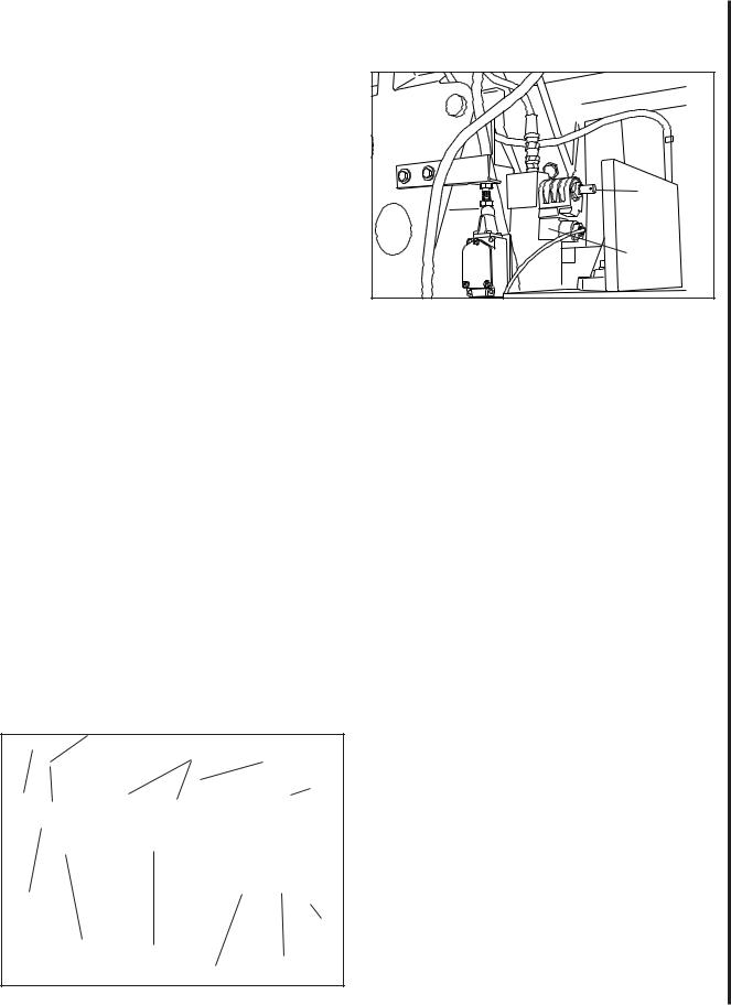
5.A red release button on the electro-magnetic valve provides a means to lower the saw head when power to the machine has been disconnected (see figure 4).
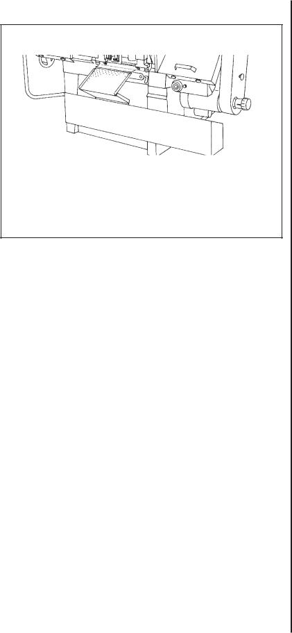
6.The rate at which the saw head moves downward is controlled by a hydraulic feed rate control located on the top, rear of the saw head (see figure 3).
7.A coolant pump switch is provided on the electrical equipment box on the back of the machine
Setting Blade Speed
1.The blade speed is controlled by an adjustment mechanism on the right end of the saw. Speed increases when the adjustment knob is turned counterclockwise. Speed decreases when the
knob is turned clockwise.
2.A placard on the drive belt guard provides recom mended speeds for various materials.
3.A speed indicator is provided on the barrel of the adjustment mechanism. The indicator provides speed indications in feet per minute and meters per minute. (The meters per minute values are shown in parenthesis on the indicator.)
4.The feed rates on the placard are expressed in meters per minute. The feed rate graduations available on the indicator may not match the recommended feed rate. An approximate speed may therefore be required. For example, to set a speed rate of 25 meters per minute, the indicator would be set about midway between 21 meters- per-minute and the 30 meters-per-minute graduations.
WARNING: TO CHANGE SPEED, THE SAW MOTOR MUST BE OPERATING.
5.Turn the speed adjustment knob to the desired rate setting as determined by the material being cut.
Coolant |
Pump |
Switch |
Figure 2: Coolant pump switch
Raising/Lowering the Saw
Head
1.Lift the saw head using the handle on the far left side of the saw head.
2.To lower the saw head, press the green pushbutton on the right side of the control panel.
3.To adjust the feed rate, adjust the feed rate control valve knob on the top of the saw head (see figure 3).
4.To lower the saw head with power off, pull and turn the red knob (manual override) on the electro-mag- netic valve (see figure 4).
Controlling the Cut:
Hydraulic Feed Control
The weight of the saw arm provides all the force needed to move the saw blade through the workpiece. In fact, if the full weight of the arm is allowed to make the cut, rapid blade wear and poor cutting accuracy will result. A hydraulic feed control is provided that gives the operator a means to control the speed and efficiency of cutting.
The hydraulic cylinder is attached between the saw base and the saw head. The hydraulic cylinder resists movement of the saw head in the downward direction. However, the hydraulic cylinder offers no resistance when the saw head is raised upward.
The amount of downward force can be controlled by using the feed rate control valve. When the valve is opened slightly, the saw head will move downward. The further the valve is opened, the faster the saw head will move downward.
The feed control is adjusted by the operator until the saw is operating efficiently. This is usually determined by observing the chip formation. (See Evaluating Blade Efficiency for more information on cutting efficiency.)
Control Box |
Blade Tensioning |
Blade Guide |
Saw Head |
|
Hand Wheel |
Supports |
Feed Rate |
|
|
|
Control |
|
|
|
Saw |
|
|
|
Head |
Speed
Control
Drive Motor |
Belt |
Cover |
Figure 3: Controls
Red |
Release |
Button |
Electro- |
Magnetic |
Valve |
Figure 4: Lowering head with power off
Evaluating Cutting Efficiency
Is the blade cutting efficiently? The best way to determine this is to observe the chips formed by the cutting blade.
If the chip formation is powdery, then the feed rate is much too light, or the blade is dull.
If the chips formed are curled, but colored — that is, either blue or straw-colored from heat generated during the cut — then the feed rate is too high.
If the chips are slightly curled and are not colored by heat — the blade is sufficiently sharp and is cutting at its most efficient rate.
Blade Selection
The cut-off saw is provided with a saw blade that is adequate for a variety of cut-off jobs on a variety of common materials. A 4/6 vari tooth bi-metal blade (5674011) and a 6/10 vari tooth bi-metal blade 9 (5674021) are available from Wilton.
See Setting Blade Speed for the speeds recommended for various materials. These selections, while appropriate for many shop cutting needs, do not encompass the wide variety of blades of special configuration (tooth pitch and set) and special alloys for cutting unusual or exotic materials.
A coarse blade could be used for a solid steel bar but a finer tooth blade would be used on a thin-wall tube. In general, the blade choice is determined by the thickness of the material; the thinner the material, the finer the tooth pitch.

A minimum of three teeth should be on the work piece at all times for proper cutting. The blade and workpiece can be damaged if the teeth are so far apart that they straddle the workpiece.
For very high production on cutting of special materials, or to cut hard-to-cut materials such as stainless steel, tool steel, or titanium, you can ask your industrial distributor for more specific blade recommendations. Also, the supplier who provides the workpiece material should be prepared to provide you with very specific instructions regarding the best blade (and coolant or cutting fluid, if needed) for the material and shape supplied.
Blade Break-in Procedures
New blades are very sharp and, therefore, have a tooth geometry which is easily damaged if a careful break-in procedure is not followed. Consult the blade manufacturer’s literature for break-in of specific blades on specific materials. However, the following procedure will be adequate for break-in of Wilton-supplied blades on lower alloy ferrous materials.
1.Clamp a round section workpiece in the vise. The workpiece should be 2 inches or larger in diameter.
2.Set the saw on low speed. Start the cut with a very light feed rate.
3.When the saw has completed 1/3 of the cut, increase the feed rate slightly and allow the saw to complete the cut.
4.Keep the same hydraulic cylinder setting and begin a second cut on the same or similar workpiece.
5.When the blade has completed about 1/3 of the cut, increase the feed rate. Watch the chip formation until cutting is at its most efficient rate and allow the saw to complete the cut (see Evaluating Blade Efficiency). The blade is now considered ready for regular service.
10
Work Setup
Securing the Workpiece for Square Cuts
1.Raise the saw head (refer to Figure 5).
2.Slide the left vise jaw far enough to the left to allow the workpiece to be placed in the vise.
3.Place the workpiece on the work table. If the workpiece is long, provide support at the other end. It may also be necessary to provide additional downward clamping to hold the workpiece securely on the work table.
4.Turn clamping hand wheel clockwise to clamp the workpiece in position against the fixed (right) vise jaw.
5.After completing the cut, turn the clamping hand wheel counterclockwise and slide the left jaw away from the workpiece.
Clamping |
|
|
Hand |
|
|
Wheel |
|
Saw Head |
|
Left Vise Jaw |
|
|
|
|
Work Table |
|
|
Figure 5: Securing workpiece
Adjusting the Vise for Angle Cuts
1.Referring to Figure 5, loosen the angle locking screw and the pivot screw on the left vise jaw.
2.Turn the locking handle on the round, angle-setting block counterclockwise to unlock the block. Slide the block until the pointer on the block is aligned with desired angle (see figure 7). Tighten the locking handle to set the angle.
3.Set the workpiece in the vise. Put the front end of the workpiece against the corner of the right vise jaw. Put the rear end of the workpiece against the angle-setting block.
4.Turn clamping hand wheel clockwise until the left vise jaw is parallel with the workpiece. Tighten the pivot screw and angle locking screw on the left vise jaw. Clamp the workpiece in position.
5.After completing the cut, turn the clamping hand wheel counterclockwise and slide the left jaw away from the workpiece.
 Loading...