


This Manual is Bookmarked
This Manual is Bookmarked
Owner's Manual
8-in x 13-in Horizontal Cut-Off Bandsaw
Model: 7015
WMH TOOL GROUP |
|
|
2420 Vantage Drive |
|
|
Elgin, Illinois 60124 |
Part No. M-7015 |
|
Ph.: 800-274-6848 |
Revision B |
02/07 |
www.wmhtoolgroup.com |
Copyright © WMH Tool |
Group |

Warranty and Service
WMH Tool Group, Inc., warrants every product it sells. If one of our tools needs service or repair, one of our Authorized Service Centers located throughout the United States can give you quick service. In most cases, any of these WMH Tool Group Authorized Service Centers can authorize warranty repair, assist you in obtaining parts, or perform routine maintenance and major repair on your WILTON® tools. For the name of an Authorized Service Center in your area call 1-800-274-6848.
MORE INFORMATION
Group distributor, or visit wiltontool.com.
WARRANTY
WILTON products carry a limited warranty which varies in duration based upon the product. (MW = Metalworking)
WHAT IS COVERED?
This warranty covers any defects in workmanship or materials subject to the exceptions stated below. Cutting tools, abrasives and other consumables are excluded from warranty coverage.
WHO IS COVERED?
This warranty covers only the initial purchaser of the product.
WHAT IS THE PERIOD OF COVERAGE?
The general WILTON warranty lasts for the time period specified in the product literature of each product.
WHAT IS NOT COVERED?
This warranty does not cover defects due directly or indirectly to misuse, abuse, negligence or accidents, normal wear-and-tear, improper repair or alterations, or lack of maintenance.
HOW TO GET SERVICE
The product or part must be returned for examination, postage prepaid, to a location designated by us. For the name of the location nearest you, please call 1-800-274-6848.
You must provide proof of initial purchase date and an explanation of the complaint must accompany the merchandise. If our inspection discloses a defect, we will repair or replace the product, or refund the purchase price, at our option.
We will return the repaired product or replacement at our expense unless it is determined by us that there is no defect, or that the defect resulted from causes not within the scope of our warranty in which case we will, at your direction, dispose of or return the product. In the event you choose to have the product returned, you will be responsible for the handling and shipping costs of the return.
HOW STATE LAW APPLIES
This warranty gives you specific legal rights; you may also have other rights which vary from state to state.
LIMITATIONS ON THIS WARRANTY
WMH TOOL GROUP LIMITS ALL IMPLIED WARRANTIES TO THE PERIOD OF THE LIMITED WARRANTY FOR EACH PRODUCT. EXCEPT AS STATED HEREIN, ANY IMPLIED WARRANTIES OR MERCHANTABILITY AND FITNESS ARE EXCLUDED. SOME STATES DO NOT ALLOW LIMITATIONS ON HOW LONG THE IMPLIED WARRANTY LASTS, SO THE ABOVE LIMITATION MAY NOT APPLY TO YOU.
WMH TOOL GROUP SHALL IN NO EVENT BE LIABLE FOR DEATH, INJURIES TO PERSONS OR PROPERTY, OR FOR INCIDENTAL, CONTINGENT, SPECIAL, OR CONSEQUENTIAL DAMAGES ARISING FROM THE USE OF OUR PRODUCTS. SOME STATES DO NOT ALLOW THE EXCLUSION OR LIMITATION OF INCIDENTAL OR CONSEQUENTIAL DAMAGES, SO THE ABOVE LIMITATION OR EXCLUSION MAY NOT APPLY TO YOU.
WMH Tool Group sells through distributors only. The specifications in WMH catalogs are given as general information and are not binding. Members of WMH Tool Group reserve the right to effect at any time, without prior notice, those alterations to parts, fittings, and accessory equipment which they may deem necessary for any reason whatsoever.
2
Table of Contents |
|
Warranty and Service.................................................................................................................................... |
2 |
Table of Contents.......................................................................................................................................... |
3 |
Warnings ....................................................................................................................................................... |
4 |
Introduction ................................................................................................................................................... |
6 |
Specifications ................................................................................................................................................ |
6 |
Machine Features ......................................................................................................................................... |
7 |
Unpacking and Assembly.............................................................................................................................. |
8 |
Electrical Connection .................................................................................................................................... |
8 |
Controls and Indicators ................................................................................................................................. |
9 |
Blade Selection ........................................................................................................................................... |
10 |
Operations................................................................................................................................................... |
10 |
Adjustments ................................................................................................................................................ |
14 |
Maintenance................................................................................................................................................ |
18 |
Cleaning ...................................................................................................................................................... |
20 |
Lubrication................................................................................................................................................... |
20 |
Coolant........................................................................................................................................................ |
20 |
Troubleshooting .......................................................................................................................................... |
21 |
Parts............................................................................................................................................................ |
23 |
Saw Stand and Bed................................................................................................................................. |
23 |
Saw Stand and Bed – Parts Breakdown ................................................................................................. |
25 |
Saw Head................................................................................................................................................ |
26 |
Saw Head – Parts Breakdown ................................................................................................................ |
29 |
Electric Assembly -- Parts and Breakdown ............................................................................................. |
30 |
Wiring Diagram ........................................................................................................................................... |
31 |
Ordering Replacement Parts....................................................................................................................... |
32 |
The specifications in this manual are given as general information and are not binding. WMH Tool Group reserves the right to effect, at any time and without prior notice, changes or alterations to parts, fittings, and accessory equipment deemed necessary for any reason whatsoever.
3

1.Read and understand the entire owner's manual before attempting assembly or operation.
2.Read and understand the warnings posted on the machine and in this manual. Failure to comply with all of these warnings may cause serious injury.
3.Replace the warning labels if they become obscured or removed.
4.The bandsaw is designed and intended for use by properly trained and experienced personnel only. If you are not familiar with the proper and safe operation of a bandsaw, do not use until proper training and knowledge have been obtained.
5.Do not use this bandsaw for other than its intended use. If used for other purposes, WMH Tool Group disclaims any real or implied warranty and holds itself harmless from any injury that may result from that use.
6.Always wear approved safety glasses/face shields while using this bandsaw. Everyday eyeglasses only have impact resistant lenses; they are not safety glasses.
7.Before operating the bandsaw, remove tie, rings, watches and other jewelry, and roll sleeves up past the elbows. Remove all loose clothing and confine long hair. Non-slip footwear or anti-skid floor strips are recommended. Do not wear gloves.
8.Wear ear protectors (plugs or muffs) during extended periods of operation.
9.Some dust created by power sanding, sawing, grinding, drilling and other construction activities contain chemicals known to cause cancer, birth defects or other reproductive harm. Some examples of these chemicals are:
xLead from lead based paint.
xCrystalline silica from bricks, cement and other masonry products.
xArsenic and chromium from chemically treated lumber.
10.Your risk of exposure varies, depending on how often you do this type of work. To reduce your exposure to these chemicals, work in a well-ventilated area and work with approved safety equipment, such as face or dust masks that are specifically designed to filter out microscopic particles.
11.Do not operate this machine while tired or under the influence of drugs, alcohol or any medication.
12.Make certain the switch is in the OFF position before connecting the machine to the power supply.
13.Make certain the machine is properly grounded.
14.Make all machine adjustments or maintenance with the machine unplugged from the power source.
15.Remove adjusting keys and wrenches. Form a habit of checking to see that keys and adjusting wrenches are removed from the machine before turning it on.
16.Keep safety guards in place at all times when the machine is in use. If removed for maintenance purposes, use extreme caution and replace the guards immediately.
17.Make sure the bandsaw is firmly placed on a secure foundation.
18.Check damaged parts. Before further use of the machine, a guard or other part that is damaged should be carefully checked to determine that it will operate properly and perform its intended function. Check for alignment of moving parts, binding of moving parts, breakage of parts, mounting and any other conditions that may affect its operation. A guard or other part that is damaged should be properly repaired or replaced.
19.Provide for adequate space surrounding work area and non-glare, overhead lighting.
20.Keep the floor around the machine clean and free of scrap material, oil and grease.
4

21.Keep visitors a safe distance from the work area. Keep children away.
22.Make your workshop child proof with padlocks, master switches or by removing starter keys.
23.Give your work undivided attention. Looking around, carrying on a conversation and “horse-play” are careless acts that can result in serious injury.
24.Maintain a balanced stance at all times so that you do not fall into the blade or other moving parts. Do not overreach or use excessive force to perform any machine operation.
25.Use the right tool at the correct speed and feed rate. Do not force a tool or attachment to do a job for which it was not designed. The right tool will do the job better and safer.
26.Use recommended accessories; improper accessories may be hazardous.
27.Maintain tools with care. Keep saw blades sharp and clean for the best and safest performance. Follow instructions for lubricating and changing accessories.
28.Turn off the machine before cleaning. Use a brush or compressed air to remove chips or debris — do not use your hands.
29.Do not stand on the machine. Serious injury could occur if the machine tips over.
30.Never leave the machine running unattended. Turn the power off and do not leave the machine until it comes to a complete stop.
31.Remove loose items and unnecessary work pieces from the area before starting the machine.
32.Always wear leather gloves when handling saw blade. The operator shall not wear gloves when operating the machine.
33.All doors shall be closed, all panels replaced, and other safety guards in place prior to the machine being started or operated.
34.Be sure that the blade is not in contact with the workpiece when the motor is started. The motor shall be started and you should allow the saw to come up to full speed before bringing the saw blade into contact with the workpiece.
35.Keep hands away from the blade area. See Figure A.
36.Remove any cut off piece carefully while keeping your hands free of the blade area.
37.Saw must be stopped and electrical supply must be cut off before any blade replacement or adjustment of blade support mechanism is done, or before any attempt is made to change the drive belts or before any periodic service or maintenance is performed on the saw.
38.Remove loose items and unnecessary workpieces from area before starting machine.
39.Bring adjustable saw guides and guards as close as possible to the workpiece.
40.Always wear protective eye wear when operating, servicing, or adjusting machinery. Eyewear shall be impact resistant, protective safety glasses with side shields complying with ANSI Z87.1 specifications. Use of eye wear which does not comply with ANSI Z87.1 specifications could result in severe injury from breakage of eye protection. See Figure B.
41.Nonslip footwear and safety shoes are recommended. See Figure C.
42.The workpiece, or part being sawed, must be securely clamped before the saw blade enters the workpiece.
43.Saw must be stopped and electrical supply cut off or machine unplugged before reaching into cutting area.
44.Avoid contact with coolant, especially guarding your eyes.
5
Familiarize yourself with the following safety notices used in this manual:
 This means that if precautions are not heeded, it may result in minor injury and/or possible machine damage.
 This means that if precautions are not heeded, it may result in serious injury or possibly even death.
Introduction
The Wilton Model 7015 Horizontal Cut-off Bandsaw is designed for high production cut-off work. Four cutting speeds and a hydraulic feed control allow the efficient cutting of virtually any material.
The Model 7015 Horizontal Cut-off Bandsaw is equipped with a coolant system that can greatly extend blade life and speed the cutting of a variety of materials that are best cut with cutting fluids and coolants.
Specifications
Model Number ........................................................................................................................................ |
7015 |
Capacity |
|
Rectangular Stock ............................................................................................................. |
8 x 12.9 Inches |
Round Stock.............................................................................................................................. |
8.9 Inches |
Flat Stock .............................................................................................................................. |
8 x 10 Inches |
At 45 Degrees ......................................................................................................................... |
8 x 8 Inches |
Speeds ....................................................................................................................... |
82, 132, 170, 235 FPM |
Motor ................................................... |
1 1/2 Horsepower, Capacitor Start, 1725 RPM, 1 Phase, 115 /220V |
Blade Size ............................................................................................................... |
1 x 0.035 x 114.5" inches |
Blade Guides.................................................................. |
Tungsten carbide tip & ball bearing, eccentric shaft |
Material.................................................................................................................... |
Tungsten carbide inserts |
Sides ............................................................................................................ |
Eccentric shaft, ball bearings |
Blade Wheel...................................................................................................... |
12 inches diameter, cast iron |
Dimensions (LWH) |
|
Length ..................................................................................................................................... |
62.5 inches |
Width ....................................................................................................................................... |
22.4 inches |
Height ............................................................................................................ |
48.4 inches (cutoff position) |
Weight ................................................................................................................. |
Approximately 551 pounds |
Vise ........................................................................................................ |
Rapid acting, screw tightening vise |
Coolant Pump ......................................................................................... |
1/8 Horsepower, 1Phase 115/220V |
6

Machine Features
Figures 1 and 2 depict the main features of the Model 7015 Horizontal Cut-Off Bandsaw. The machine consists of a machine base onto which is installed a saw head.
Figure 1
Machine Base
The machine base consists of a coolant collection pan mounted on two panels that form the legs of the machine. A shelf is provided under the collection pan that supports a coolant tank.
The machine bed mounts on the top of the collection pan. The bed supports the vise and the vise-tightening lead screw.
The coolant tank is equipped with a pump/motor assembly. The pump/motor circulates coolant through tubing to cool and lubricate the saw blade, the blade guides, and the workpiece.
A drainpipe is provided to connect the collection pan to the coolant tank. A screen is provided in the collection pan to screen-out cutting debris as the coolant drains into the coolant tank. Coolant is added to the tank by pouring coolant into the collection pan. The tank is easily removed from its shelf for cleaning and maintenance.
Saw Head
The saw head (Figure 2) consists of a drive motor, drive pulleys, gearbox, blade wheels, blade guides and supports, control panel, blade tension/blade tracking mechanism, wire brush, and the saw blade.
The drive motor is mounted on a pivoting plate that swings outward to provide V-belt tension. The motor is fitted with a step pulley; the V-belt connects to a second step pulley that is mounted on the input shaft of the gearbox.
A speed-reducing gearbox is mounted on the back side of the blade wheel box on the right side of the machine. The blade wheel (drive wheel) is installed on the output shaft of the gearbox.
A second blade wheel is located in a blade wheel box on the left of the machine. The blade wheel (driven wheel) is mounted on a shaft that is part of the blade tension/tracking mechanism. The blade tension mechanism is used to tighten the saw blade on the blade wheels.
Figure 2
7

The mechanism also has adjustment screws that enable the saw blade to “track” evenly on the blade wheels. The adjustment screws change the angle of the driven blade wheel shaft so the wheels are aligned. Tracking adjustments are generally made after the saw blade is changed but may be required periodically due to wear over time.
An electrical enclosure is attached to the leg panel on the right side of the machine. The enclosure contains the switches and fuses required for operation and protection of the drive motor (Figure 3).
Remove the saw from the shipping skid; discard any hold-down devices. Place the saw on the shop floor; secure the saw to the floor using mounting anchors secured through four holes in the machine base. If the saw will be used to cut long pieces of stock, allow plenty of room for the length of the stock.
Minimal assembly is required (see to Fig. 4), consisting of mounting the control box, motor, pulley guard/cover assembly and motor drive belt. The mounting hardware is already in place on the saw head. Loosen or remove the hardware, placing the components (listed above) in place and secure. For the drive belt, refer to the Drive Belt section on page 19.
Figure 3
Work Stop
A work stop is provided with the machine to allow cutting multiple pieces of identical length (refer to Figure 12). The stop consists of a rod onto which is installed a stop bracket, a tapered stop, a clamping knob and a locking handle. The rod is installed in a bore in the front of the saw bed. The stop bracket is positioned on the rod with the tapered stop toward the end of the workpiece. The bracket is moved in or out on the rod to establish the length of the workpiece.
Control Panel
The control panel is mounted on the top of the saw head. Refer to the Controls and Indicators section (page 9) for a description of the controls.
Unpacking and Assembly
Machine Setup
The cut-off saw has been pre-adjusted at the factory and several test pieces have been cut to verify cutting accuracy.
Figure 4
Electrical Connection
 Electrical connection must be made by a licensed electrician. The wiring methods and practices must comply with local electrical codes.
 The machine uses high voltage electrical power that poses a significant risk of serious injury or death if proper precautions are not observed
Connect the machine to the electrical power branch circuit (refer to the Wiring section on page 31). Observe the following guidelines when connecting the saw to the power source.
1.Make sure the saw is disconnected from the electrical power branch circuit (trip the required circuit breakers or remove the required fuses).
8
2.Place a warning placard or tag on the service panel to prevent accidental electrical shock.
3.When installing the motor power cord into a receptacle, make sure the plug is compatible with the receptacle.
4.When using hard-wired connections, connect the wires as shown in the Wiring Data section.
5.Install the fuses or reset the breakers. Check operation of the saw.
Controls and Indicators
Control Panel
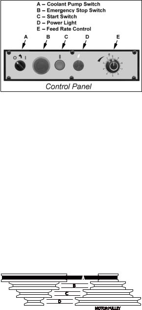
The operating controls for the cut-off saw are located on the control panel (Figure 5) and consist of the following controls and indicators:
Coolant Pump Switch – turns the coolant pump on and off.
Emergency Stop Switch – press to stop the drive motor. Note: A micro switch also stops the motor when the workpiece is cut and the saw head is completely down.
Start Switch – press to start the drive motor. The saw head must be in the raised position.
Power Light – indicates that machine is plugged in and the outlet circuit breaker is turned on. The machine does not need to be running for the power light to be on.
Feed Rate Control – this knob is used to set the amount of downward force that is applied to the saw blade. The feed rate is proportional to the opening of the valve. When set to zero, the saw head is locked in the raised position. Increasing the valve opening (counterclockwise adjustment) increases the feed rate; decreasing the valve opening (clockwise adjustment) reduces the feed rate.
Blade Speeds
The Model 7015 horizontal cut-off bandsaw has four blade speeds. The different speeds are obtained by changing the position of the motor drive V-belt on step pulleys. Change blade speeds as follows:
1.Disconnect the electrical power from the cut-off saw branch circuit to prevent accidental motor start-up
2.Set the saw head at the fully down position.
3.Remove the knob from the drive belt cover. Swing cover out and downward to expose the V-belt and pulleys.
4.Loosen the drive motor locking handle. Pivot the motor inward to slacken the belt.
5.Select the speed using the placard on the cover. Put the V-belt in the pulley grooves of the pulley for the desired speed. Refer to Figure 6 for belt locations and the speeds available.
Figure 5
|
|
Belt Speed |
|
Position |
|
Material to Be Cut |
60Hz |
50Hz |
|||
|
|
|
|
|
Belt |
|
fpm |
mpm |
fpm |
mpm |
|
|
|
|
|
|
|
Tool Steel, Stainless |
|
|
|
|
|
Steel, Alloy Steel, |
|
|
|
|
|
Phosphor Bronze, Hard |
82 |
25 |
68 |
21 |
A |
Bonze, Hard Cast Iron, |
|
|
|
|
|
Malleable Iron |
|
|
|
|
|
|
|
|
|
|
|
Mild Steel, Soft Cast Iron, |
|
|
|
|
|
Medium Hard Brass, |
132 |
40 |
110 |
33 |
B |
Medium Hard Bronze |
|
|
|
|
|
|
|
|
|
|
|
Soft Brasses and |
|
|
|
|
|
Bronzes, Hard Aluminum, |
170 |
51 |
142 |
43 |
C |
Plastics |
|
|
|
|
|
|
|
|
|
|
|
Plastics, Soft and Medium |
|
|
|
|
|
Aluminum, Wood, Other |
235 |
71 |
196 |
60 |
D |
Light Materials |
|
|
|
|
|
|
|
|
|
|
|
Note: Belt position A shown below
Figure 6
6.Pivot the motor outward to tighten the V-belt. Tighten the locking handle.
7.Check V-belt tension by pushing the V-belt firmly downward; press down about midway between the pulleys. When properly tightened, the V-belt should depress no more than the width of the belt.
9
Blade Selection
The cut-off saw is delivered with a saw blade that is adequate for a variety of cut-off jobs on a variety of common materials. A 10-tooth, general-purpose blade is provided as standard equipment with the machine.
An optional 8-tooth blade and an optional 14-tooth blade are available from Wilton. (Refer to the Parts section for saw blade part numbers.)
Refer to Figure 5 for the speeds recommended for various materials. These speeds, while appropriate for many common shop cutting needs, do not encompass the wide variety of special blade configurations (tooth pitch and set) and special alloys for cutting unusual or exotic materials.
A coarse blade could be used for a solid steel bar, but a finer tooth blade would be used on a thin-wall steel tube. In general, the blade choice is determined by the thickness of the material; the thinner the materials; the finer the tooth pitch.
A minimum of three teeth should be on the workpiece at all times for proper cutting. The blade and workpiece can be damaged if the teeth are so far apart that they straddle the workpiece.
For very high production on cutting of special materials, or to cut hard-to-cut materials such as stainless steel, tool steel, or titanium, you can ask your industrial distributor for more specific blade recommendations. The supplier that provides the workpiece material should be able to provide you with very specific instructions regarding the best blade (and coolant or cutting fluid, if needed) for the material or shape supplied.
Blade Break-in Procedures
New blades are very sharp and, therefore, have a tooth geometry that is easily damaged if a careful break-in procedure is not followed. Consult the blade manufacturer’s literature for break-in of specific blades on specific materials. However, the following procedure will be adequate for break-in of Wilton-supplied blades on lower alloy ferrous materials.
1.Clamp a section of round stock in the vise. The stock should be 2 inches or larger in diameter.
2.Operate the saw at low speed. Start the cut with a very light feed rate.
3.When the saw has completed 1/3 of the cut, increase the feed rate slightly and allow the saw to complete the cut.
4.Keep the hydraulic cylinder needle valve in the same position and begin a second cut on the same or similar workpiece.
5.When the blade has completed about 1/3 of the cut, increase the feed rate.
Watch the chip formation until cutting is at its most efficient rate and allow the saw to complete the cut (refer to Evaluating Blade Efficiency on page 10). The blade is now considered ready for use.
Operations
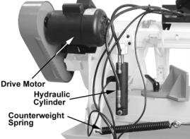
Hydraulic Feed Control
The weight of the saw head provides the force needed to cut through the workpiece. The cut-off saw has a hydraulic cylinder that controls the feed rate of the saw.
The hydraulic feed control circuit consists of a single acting hydraulic cylinder (Figure 7) and a feed rate control (Figure 5). The feed control cylinder resists motion in the downward direction to control the feed rate. The control cylinder offers no resistance when raised upward.
The feed rate control knob (Figure 5) controls the rate at which the saw head is lowered. The control knob (needle valve) controls the rate at which the hydraulic fluid is released from the hydraulic cylinder. When the needle valve is closed, the cylinder is locked. With the needle valve slightly open, the cylinder permits slow, or light, downward force. Opening the needle valve further increases the feed rate and applies more weight to the saw blade and workpiece.
The needle valve is adjusted until the saw is operating efficiently. The efficiency of operation is usually evaluated by observing chip formation. Blade efficiency is further described below.
Figure 7
10
 Loading...