


Operating Instructions — Parts Manual
Wilton Belt and Disc Sanding Machine
Model: 4210
WHM TOOL GROUP |
|
2420 Vantage Drive |
|
Elgin, Illinois 60123 |
Part No. 5511717 |
Ph.: 800-274-6848 |
Revision A8 02/05 |
www.wmhtoolgroup.com |
Copyright © WMH Tool Group |
This manual has been prepared for owners of Wilton Model 4210 Belt and Disc Sanding Machine. Its purpose is to promote safety through the use of accepted operating and maintenance procedures. To obtain maximum life and efficiency from your Belt and Disc Sander and to aid in using it safely, please read this manual thoroughly and follow the instructions carefully.
Warranty
WMH Tool Group warrants every product it sells. If one of our tools needs service or repair, one of our Authorized Repair Stations located throughout the United States can give you quick service.
In most cases, any one of these WMH Tool Group Repair Stations can authorize warranty repair, assist you in obtaining parts, or perform routine maintenance and major repair on your JET, Wilton, Powermatic, or Performax tools.
For the name of an Authorized Repair Station in your area, please call 1-800-274-6848, or visit www.wmhtoolgroup.com
More Information
WMH Tool Group is consistently adding new products to the line. For complete, up-to-date product information, check with your local WMH Tool Group distributor, or visit www.wmhtoolgroup.com
WMH Tool Group Industrial Metalworking Warranty
WMH Tool Group makes every effort to assure that its products meet high quality and durability standards and warrants to the original retail consumer/purchaser of our products that each product be free from defects in materials and workmanship as follows: TWO (2) YEAR LIMITED WARRANTY* ON ANY MECHANICAL COMPONENT, ONE (1) YEAR LIMITED WARRANTY ON ANY ELECTRICAL COMPONENT. WMH This Warranty does not apply to defects due directly or indirectly to misuse, abuse, negligence or accidents, normal wear-and- tear, repair or alterations outside our facilities, or to a lack of maintenance.
WMH TOOL GROUP LIMITS ALL IMPLIED WARRANTIES TO THE PERIOD SPECIFIED ABOVE, FROM THE DATE THE PRODUCT WAS PURCHASED AT RETAIL. EXCEPT AS STATED HEREIN, ANY IMPLIED WARRANTIES OR MERCHANTIBILITY AND FITNESS ARE EXCLUDED. SOME STATES DO NOT ALLOW LIMITATIONS ON HOW LONG THE IMPLIED WARRANTY LASTS, SO THE ABOVE LIMITATION MAY NOT APPLY TO YOU. WMH TOOL GROUP SHALL IN NO EVENT BE LIABLE FOR DEATH, INJURIES TO PERSONS OR PROPERTY, OR FOR INCIDENTAL, CONTINGENT, SPECIAL, OR CONSEQUENTIAL DAMAGES ARISING FROM THE USE OF OUR PRODUCTS. SOME STATES DO NOTALLOW THE EXCLUSION OR LIMITATION OF INCIDENTAL OR CONSEQUENTIAL DAMAGES, SO THEABOVE LIMITATION OR EXCLUSION MAY NOTAPPLY TO YOU.
To take advantage of this warranty, the product or part must be returned for examination, postage prepaid, to an Authorized Repair Station designated by our office. Proof of purchase date and an explanation of the complaint must accompany the merchandise. If our inspection discloses a defect, we will either repair or replace the product, or refund the purchase price if we cannot readily and quickly provide a repair or replacement, if you are willing to accept a refund. We will return repaired product or replacement at WMH Tool Group’s expense, but if it is determined there is no defect, or that the defect resulted from causes not within the scope of WMH Tool Group’s warranty, then the user must bear the cost of storing and returning the product. This warranty gives you specific legal rights; you may also have other rights, which vary from state to state.
WMH Tool Group sells through distributors only. WMH Tool Group reserves the right to effect at any time, without prior notice, those alterations to parts, fittings, and accessory equipment, which they may deem necessary for any reason whatsoever.
WMH Tool Group Industrial Metalworking’s 2 year limited warranty is based on one 8-hour work shift or 2080 hours per year. The warranty period is good for 2 years of a total of 4160 hours whichever comes first.

Table of Contents |
|
Cover Page........................................................................................................................... |
1 |
General Specifications .......................................................................................................... |
4 |
Operating Precautions .......................................................................................................... |
5 |
Introduction ........................................................................................................................... |
7 |
Operating Instructions........................................................................................................... |
9 |
Maintenance ........................................................................................................................ |
11 |
Wiring Diagram ................................................................................................................... |
14 |
Troubleshooting .................................................................................................................. |
16 |
Replacement Parts ............................................................................................................. |
17 |
Wiring Diagram ................................................................................................................... |
21 |
3
General Specifications
The Wilton Model 4210 Belt and Disc Sanding Machine is ideal for all shops. This versatile machine can be used to grind, sand, finish, and contour all types of parts including metal, wood, plastic, and composite materials. Because of these capabilities, the Wilton sander eliminates the need for multiple machines to perform the same tasks.
|
Specifications |
Wilton Belt/Disc Sander, Model 4210 |
|
|
|
|
Belt Size |
6" x 48" |
|
|
|
|
Disc Size |
10" |
|
|
|
4 |
Motor |
|
Horsepower |
1 HP |
|
|
Voltage |
115/230 Vac (pre-wired for 115 Vac) |
|
|
|
|
Switch |
Removable Safety Key |
|
|
|
|
Platen |
Cast Iron |
|
|
|
|
Tables |
Cast Iron (2) |
|
|
|
|
Belt Speed |
1650 SFPM |
|
|
|
|
Disc Speed |
2100 RPM |
|
|
|
|
Dust Collection Shrouds |
Two (standard) |
|
|
|
|
Weight |
120 lbs. |
|
|
|

|
|
|
|
|
|
|
|
|
General Machinery Cautions |
- Never operate with machine guards missing. |
|
- Misuse of this machine can cause serious injury. |
- Always wear safety glasses with side shields (See |
|
- For safety, machine must be set up, used and |
ANSI Z87.1) |
|
serviced properly. |
- Never wear loose clothing or jewelry. |
|
- Read, understand and follow instructions in the |
- Never overreach — you may slip and fall into the |
|
operator’s and parts manual which was shipped with |
machine. |
|
your machine. |
- Never leave machine running while you are away |
|
When setting up machine: |
from it. |
|
- Always avoid using machine in damp or poorly |
- Always shut off the machine when not in use. |
|
lighted work areas. |
When servicing machine: |
|
- Always be sure machine is securely anchored to |
- Always unplug machine from electrical power while |
|
the floor. |
servicing. |
|
- Always keep machine guards in place. |
- Always follow instructions in operators and parts |
|
- Always put start switch in “OFF” position before |
manual when changing accessory tools or parts. |
|
plugging in machine. |
- Never modify the machine without consulting Wilton |
|
When using machine: |
Corporation. |
|
You — the stationary power tool user — hold the key to safety.
Read and follow these simple rules for best results and full benefits from your machine. Used properly, Wilton’s machinery is among the best in design and safety. However, any machine used improperly can be rendered inefficient and unsafe. It is absolutely mandatory that those who use our products be properly trained in how to use them correctly. They should read and understand the Operators and Parts Manual as well as all labels affixed to the machine. Failure in following all of these warnings can cause serious injuries.
Machinery general safety warnings |
9. Maintain all machine tools with care. Follow all |
|
1. Always wear protective eye wear when operating |
maintenance instructions for lubricating and the |
|
machinery. Eye wear shall be impact resistant, |
changing of accessories. No attempt shall be made |
|
protective safety glasses with side shields which |
to modify or have makeshift repairs done to the |
|
comply with ANSI Z87.1 specifications. Use of eye |
machine. This not only voids the warranty but also |
|
wear which does not comply with ANSI Z87.1 specifi- |
renders the machine unsafe. |
|
cations could result in severe injury from breakage of |
10. Machinery must be anchored to the floor. |
|
eye protection. |
11. Secure work. Use clamps or a vise to hold work, |
|
2. Wear proper apparel; no loose clothing or jewelry |
when practical. It is safer than using your hands and |
|
which can get caught in moving parts. Rubber soled |
it frees both hands to operate the machine. |
5 |
footwear is recommended for best footing. |
12. Never brush away chips while the machine is in |
|
3. Do not overreach. Failure to maintain proper |
operation. |
|
working position can cause you to fall into the |
13. Keep work area clean. Cluttered areas invite |
|
machine or cause your clothing to get caught — |
accidents. |
|
pulling you into the machine. |
14. Remove adjusting keys and wrenches before |
|
4. Keep guards in place and in proper working |
turning machine on. |
|
order. Do not operate the machine with guards |
15. Use the right tool. Don’t force a tool or attach- |
|
removed. |
ment to do a job it was not designed for. |
|
5. Avoid dangerous working environments. Do not |
16. Use only recommended accessories and follow |
|
use stationary machine tools in wet or damp loca- |
manufacturers instructions pertaining to them. |
|
tions. Keep work areas clean and well lit. |
17. Keep hands in sight and clear of all moving parts |
|
6. Avoid accidental starts by being sure the start |
and cutting surfaces. |
|
switch is “OFF” before plugging in the machine. |
18. All visitors should be kept at a safe distance from |
|
7. Never leave the machine running while unattended. |
the work area. Make workshop completely safe by |
|
8. Disconnect electrical power before servicing. |
using padlocks, master switches, or by removing |
|
Whenever changing accessories or general mainte- |
starter keys. |
|
nance is done on the machine, electrical power to the |
19. Know the tool you are using — its application, |
|
machine must be disconnected before work is done. |
limitations, and potential hazards. |
|

|
General Electrical Cautions |
|
|
Wire sizes |
||||||||||||
|
This machine should be grounded in accordance with |
Caution: for circuits which are far away from the |
||||||||||||||
|
the National Electrical Code and local codes and |
|
|
electrical service box, the wire size must be in- |
||||||||||||
|
ordinances. This work should be done by a qualified |
creased in order to deliver ample voltage to the motor. |
||||||||||||||
|
electrician. The machine should be grounded to |
|
|
To minimize power losses and to prevent motor |
||||||||||||
|
protect the user from electrical shock. |
|
|
overheating and burnout, the use of wire sizes for |
||||||||||||
|
|
|
|
|
|
|
|
|
|
branch circuits or electrical extension cords accord- |
||||||
|
|
|
|
|
|
|
|
|
|
ing to the following table is recommended: |
||||||
|
|
|
|
|
|
|
|
|
|
|
|
|
|
|
||
|
Conductor length |
|
AWG (American wire gauge) number |
|
|
|
|
|
||||||||
|
|
|
|
|
|
|
|
|
|
|
|
|
|
|
|
|
|
0-50 feet |
|
240 volt lines |
|
120 volt lines |
|
|
|
|
|
||||||
|
|
No. 14 |
|
No. 14 |
|
|
|
|
|
|||||||
|
50-100 feet |
|
No. 14 |
|
No. 12 |
|
|
|
|
|
||||||
|
Over 100 feet |
|
No. 12 |
|
No. 8 |
|
|
|
|
|
||||||
|
|
|
|
|
|
|
|
|
|
|
|
|
|
|
||
|
Safety Requirements for Abrasive Sanding Machines |
|||||||||||||||
|
Abrasive sanding can be hazardous to operators and |
for wobble, runout, or any unbalanced condition. If |
||||||||||||||
|
bystanders. Sanding sparks, chips and dust particles |
the disc is not operating accurately and smoothly, |
||||||||||||||
|
thrown off by the sanding disc can cause serious |
|
|
immediately stop the motor and make repairs before |
||||||||||||
|
injury by contact or inhalation. To avoid injuries you |
attempting any sanding operations. |
||||||||||||||
|
must comply with the following safety requirements: |
7. Abrasive discs must be stored in a controlled |
||||||||||||||
|
1. Always wear protective eyewear when operating |
environment area. Relative humidity should be 35% |
||||||||||||||
|
machinery. Eye wear shall be impact resistant, |
|
|
to 50% and the temperature should be between 60 |
||||||||||||
|
protective safety glasses with side shields which |
|
|
and 80 degrees Farenheit. Failure to do so could |
||||||||||||
|
comply with ANSI Z87.1. Use of eye wear which |
|
|
cause premature disc failure. |
||||||||||||
|
does not comply with ANSI Z87.1 specifications could |
8. Examine the face of the sanding disc carefully. |
||||||||||||||
|
result in severe injury from breakage of eye protec- |
Excessive sanding which wears down to the backing |
||||||||||||||
|
tion. See Figure A, below. |
|
|
|
|
|
|
material can tearing of the disc. Never use a disc |
||||||||
|
2. Wear leather safety gloves, arm guards, leather |
which shows backing, nicks or cuts on the surface or |
||||||||||||||
|
aprons and safety shoes. |
|
|
|
|
|
|
edge or damage due to creasing or poor handling. |
||||||||
|
3. A dust collection system is recommended, |
|
|
9. When installing a new disc, be certain the disc is |
||||||||||||
|
Operator shall also wear a dust mask at all times. |
|
|
accurately centered on the drive wheel. Failure to do |
||||||||||||
|
See Figure B, below. |
|
|
|
|
|
|
so could cause a serious unbalanced condition. |
||||||||
|
4. Additional precautions may be necessary for |
|
|
10. Always present the workpiece to the wheel while |
||||||||||||
|
sanding materials which are flammable or have other |
resting the workpiece firmly on the table. Failure to |
||||||||||||||
|
hazardous properties. You should always consult the |
do so could result in damage to the workpiece or |
||||||||||||||
6 |
manufacturer of such materials for instructions on |
throwing of the workpiece off the wheel. |
||||||||||||||
|
sanding and handling. |
|
|
|
|
|
|
11. Safety shoes which comply with ANSI Z41.1 shall |
||||||||
|
5. Do not force or jamb the workpiece into the |
|
|
be worn. See Figure C. |
||||||||||||
|
sanding disc. |
|
|
|
|
|
|
12. Personal hearing protection such as ear plugs or |
||||||||
|
6. Before sanding, always allow the motor to come |
ear muffs shall be used to protect against the effect |
||||||||||||||
|
up to operating speed, then check the sanding disc |
of noise exposure. See Figure D. |
||||||||||||||
|
|
|
|
|
|
|
|
|
|
|
|
|
|
|
|
|
|
|
|
|
|
|
|
|
|
|
|
|
|
|
|
|
|
|
|
|
|
|
|
|
|
|
|
|
|
|
|
|
|
|
|
|
|
|
|
|
|
|
|
|
|
|
|
|
|
|
|
|
|
|
|
|
|
|
|
|
|
|
|
|
|
|
|
|
|
|
|
|
|
|
|
|
|
|
|
|
|
|
|
|
|
|
|
|
|
|
|
|
|
|
|
|
|
|
|
|
|
|
Figure A |
Figure B |
Figure C |
Figure D |

Introduction
This manual includes operating and maintenance instructions for the Wilton Model 4210 Belt and Disc Sander. This manual also includes parts listings and illustrations of replaceable parts.
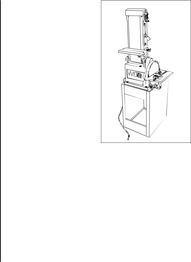
Belt and Disc Sander
Features
Figures 1 and 2 depict the main features of the Wilton Model 4210 Belt and Disc Sander. (Specifications for the sanding machine are provided on page 3.)
Tracking Adjustment |
Belt Tensioning Lever |
Belt Work Table |
Clamping Knob |
Sanding Disk |
Miter Gauge |
Disc |
Debris |
Duct |
Disc Work Table |
Clamping Knob |
Figure 1: Belt and Disc Sander Features
(Right Side View)
Sanding Belt |
|
Belt Guard |
Belt Sander |
|
|
Platen Housing |
Work Table |
|
|
Debris Duct |
|
On/Off |
|
Switch |
|
|
Machine |
|
Base |
|
Stand |
Power Cord |
|
Figure 2: Belt and Disc Sander Features
(Left Side View)
The sander has both a sanding belt and a sanding |
7 |
disc for use on a variety of work pieces and materi- |
|
als. |
|
The platen housing for the belt sander can be positioned vertically or horizontally. When in the vertical position, the drum at the upper end of the platen housing can be used for contouring. A tracking adjustment mechanism for the sanding belt is provided at the upper end of the platen housing.
The platen housing has a lever that is used to apply tension to the sanding belt. The sanding belt is easily replaced by releasing the tension lever, removing a sanding shroud and dust collection duct at the bottom of the platen housing, and slipping the belt from the belt sander drums. Installation is the reverse of the removal steps.

The disc sander consists of an aluminum disc onto which is installed an adhesive-backed sanding and other abrasive discs. The disc is contained within a ducted shroud.
The sanding disc can be replaced by removing the table and a cover over the lower portion of the disc. If desired, the aluminum disc can be removed from its drive shaft to ease replacement of the sanding disc.
The drive motor for the belt and disc sander is attached to the underside of the machine base. An ON/OFF switch is mounted on the machine base on the side opposite the disc sander. Electrical wiring for the motor enters the machine base below the ON/ OFF switch and is routed to the switch and motor inside the machine base.
The belt and disc sander is driven by V-belts connected to the drive motor. A pulley on the motor shaft drives a V-belt that drives a dual-groove pulley on an idler shaft. A second V-belt is installed in the second groove of the dual-groove pulley and connects to a pulley on belt sander drive shaft.
The aluminum sanding disc is driven off the end of the idler shaft. A shaft connected to the second V- belt pulley drives the belt sander drive drum.
The belt and disc sander is mounted on a stand that can be secured to the floor to stabilize the machine. The stand has a door for access to the fasteners for the machine base.
8
Installation and Setup
Mounting
It is recommended that the belt and disc sander be secured to the floor for safe operation. The machine stand has mounting holes in a flange on the inside of stand enclosure. The stand can be secured to the floor using these mounting holes.
Electrical Connection
Refer to the Wiring Data section for wiring information. Electrical power should be connected by a qualified electrician. Observe local electrical codes when connecting and grounding the machine.
 Loading...