


 Loading...
This Manual is Bookmarked
Operating Instructions — Parts Manual
Disc, Belt, and Combination Disc/Belt Sanders
Models: 4200A, 4300A, 4400A
4200A Disc/Belt Sander |
4300A 6 Inch Belt Sander |
4400A 12 Inch Disc Sander |
WHM TOOL GROUP |
|
2420 Vantage Drive |
|
Elgin, Illinois 60123 |
Part No. 5511365 |
Ph.: 800-274-6848 |
Revision E2 10/04 |
www.wmhtoolgroup.com |
Copyright © WMH Tool Group |

This manual has been prepared for the owner and operators of a Wilton Sander. Its purpose, aside from machine operation, is to promote safety using accepted operating and maintenance procedures. To obtain maximum life and efficiency from your Sander and to aid in using it safely, please read this manual thoroughly and follow instructions carefully.
Warranty and Service
WMH Tool Group warrants every product it sells. If one of our tools needs service or repair, one of our Authorized Repair Stations located throughout the United States can provide quick service or information.
In most cases, a WMH Tool Group Repair Station can assist in authorizing repair work, obtaining parts, or perform routine or major maintenance repair on your Wilton product.
For the name of an Authorized Repair Station in your area, please call 1-888-594-5866, or visit our web site at www.wmhtoolgroup.com
More Information
Remember, WMH Tool Group is consistently adding new products to the line. For complete, up-to-date product information, check with your local WMH Tool Group distributor, or visit our web site at www.wmhtoolgroup.com
WMH Tool Group Warranty
WMH Tool Group makes every effort to assure that its products meet high quality and durability standards and warrants to the original retail consumer/purchaser of our products that each product be free from defects in materials and workmanship as follows: 1 YEAR LIMITED WARRANTY ON ALL PRODUCTS UNLESS SPECIFIED OTHERWISE. This Warranty does not apply to defects due directly or indirectly to misuse, abuse, negligence or accidents, normal wear-and-tear, repair or alterations outside our facilities, or to a lack of maintenance.
WMH TOOL GROUP LIMITS ALL IMPLIED WARRANTIES TO THE PERIOD SPECIFIED ABOVE, BEGINNING FROM THE DATE THE PRODUCT WAS PURCHASED AT RETAIL. EXCEPT AS STATED HEREIN, ANY IMPLIED WARRANTIES OR MERCHANTABILITY AND FITNESS ARE EXCLUDED. SOME STATES DO NOT ALLOW LIMITATIONS ON HOW LONG THE IMPLIED WARRANTY LASTS, SO THE ABOVE LIMITATION MAY NOT APPLY TO YOU. IN NO EVENT SHALL WMH TOOL GROUP BE LIABLE FOR DEATH, INJURIES TO PERSONS OR PROPERTY, OR FOR INCIDENTAL, CONTINGENT, SPECIAL, OR CONSEQUENTIAL DAMAGES ARISING FROM THE USE OF OUR PRODUCTS. SOME STATES DO NOT ALLOW THE EXCLUSION OR LIMITATION OF INCIDENTAL OR CONSEQUENTIAL DAMAGES, SO THE ABOVE LIMITATION OR EXCLUSION MAY NOT APPLY TO YOU.
To take advantage of this warranty, the product or part must be returned for examination, postage prepaid, to an Authorized Repair Station designated by our office. Proof of purchase date and an explanation of the complaint must accompany the merchandise. If our inspection discloses a defect, we will either repair or replace the product at our discretion, or refund the purchase price if we cannot readily and quickly provide a repair or replacement. We will return the repaired product or replacement at WMH Tool Group’s expense, but if it is determined there is no defect, or that the defect resulted from causes not within the scope of WMH Tool Group’s warranty, then the user must bear the cost of storing and returning the product. This warranty gives you specific legal rights; you may also have other rights, which vary from state to state.
WMH Tool Group sells through distributors only. Members of the WMH Tool Group reserve the right to effect at any time, without prior notice, alterations to parts, fittings and accessory equipment, which they may deem necessary for any reason whatsoever.

Table of Contents |
|
Cover Page ......................................................................................................................................... |
1 |
Warranty .............................................................................................................................................. |
2 |
Table of Contents ................................................................................................................................ |
3 |
Machine and Manual Overview ............................................................................................................ |
4 |
General Specifications......................................................................................................................... |
5 |
Warnings ............................................................................................................................................. |
6 |
Operating Instructions .......................................................................................................................... |
8 |
Maintenance ...................................................................................................................................... |
10 |
Setup and Installation ........................................................................................................................ |
13 |
Troubleshooting ................................................................................................................................. |
18 |
Wiring Diagrams ................................................................................................................................ |
19 |
Replacement Parts ............................................................................................................................ |
20 |
Accessories ....................................................................................................................................... |
28 |
3

Machine and Manual Overview
WiltonAbrasive Finishing Machines are available in three different configurations: disc, belt, and combination disc and belt. Each configuration is a rugged, heavy-duty machine designed for maximum high production work in an industrial environment.
The speed of stock removal and the quality of finish achieved is determined largely by the aggressiveness of the abrasive disc or belt mounted on the machine. With very aggressive grits, these machines are typically considered grinding machines. With very fine grits, these machines are typically considered sanding machines. Whatever you call them, and however you use them, the instructions in this manual will help you use them safely and productively.
You will note there are several types of electrical systems available for these machines. All of these systems are equally effective in providing power to the grinding mechanism -- however, local codes and the type of environment in which the machine is used will often be a factor in your choice of system.
Instructions in this manual assume that you are using one of the Model 4200A series Belt and Disc machines. If you have a disc only, or belt only machine, you can bypass those instructions which do not apply to you.
4

General Specifications
|
Disc Sander |
Belt Sander |
Disc/Belt Sander |
|
Table size |
12x16 3/8 in. (254x416mm) |
7 3/8x14 3/4 in. (187x355mm) |
Disc:12x16 3/8 in. (254x416mm) |
|
|
|
|
Belt: 7 3/8x14 3/4 in. |
|
|
|
|
(187x355mm) |
|
Table tilt |
45° down, 20° up |
45° down, 20° up |
(both) 45° down, 20° up |
|
Miter gauge groove |
3/8x3/4 in. (9.5x19mm) |
3/8x3/4 in. (9.5x19mm) |
(both) 3/8x3/4 in. (9.5x19mm) |
|
Disc diameter |
12 in. (305mm) |
|
12 in. (305mm) |
|
Disc Speed |
1960 RPM |
|
1960 RPM |
|
Platen size |
|
6 1/4x14 3/4 in. (159x375mm) |
6 1/4x14 3/4 in. (159x375mm) |
|
Belt size |
|
6x48 in. (152x1214mm) |
6x48 in. (152x1214mm) |
|
Belt speed |
|
2850 SFM |
2850 SFM |
|
Dimensions |
29x17x42 3/4 in. |
|
|
|
(depth, W, H) |
(1070x725x4250mm) |
|
|
|
Dimensions w/platen |
|
19x16x57 1/2 in. |
19x16x57 1/2 in. |
|
vertical (depth,W, H) |
|
(475x400x1437mm) |
(475x400x1437mm) |
5 |
Dimensions w/platen |
|
25 1/2x16x43 in. |
25 1/2x16x43 in. |
|
horizontal |
|
(637x400x1075mm) |
(637x400x1075mm) |
|
(depth, W, H) |
|
|
|
|
Motor options |
Model 4400A 1 ph. 1.5HP |
Model 4300A 1 ph. 1.5HP |
Model 4200A 1 ph. 1.5HP |
|
|
115/230V |
115/230V |
115/220V |
|
|
Model 4401A 3 ph. 1.5HP |
Model 4301A 3 ph. 1.5HP |
Model 4202A 3 ph. 1.5HP |
|
|
230V/460V |
230V/460V |
230V/460V |
|
|
Model 4403A 3 ph. 1.5HP |
Model 4303A 3 ph. 1.5HP 230/ |
Model 4204A 3 ph. 1.5HP 230/ |
|
|
230/460V (connected 460) |
460V (connected 460) full JIC, |
460V (connected 460) full JIC, |
|
Weight |
full JIC, 110V at the switch |
110V at the switch |
110V at the switch |
|
unassembled |
|
|
|
|
|
164 lbs. (74 kg.) |
211 lbs. (96 kg.) |
250 lbs. (113 kg.) |
|

|
|
|
|
|
|
|
|
|
|
|
|
General Machinery Cautions |
When using the machine: |
||
- Misuse of this machine can cause serious injury. |
- Never operate the machine with safety guards missing. |
||
- Always wear safety glasses with side shields (See ANSI |
|||
- For safety, the machine must be set up, used and |
|||
Z87.1) |
|||
serviced properly. |
|||
- Never wear loose clothing or jewelry. |
|||
- Read, understand and follow the instructions in the |
|||
- Never overreach — you may slip and fall into the |
|||
operator’s and parts manual which was shipped with |
|||
machine. |
|||
your machine. |
|||
- Never leave the machine running while unattended. |
|||
When setting up the machine: |
|||
- Always shut the machine off when not in use. |
|||
- Always avoid using the machine in damp or poorly |
|||
When servicing the machine: |
|||
lighted work areas. |
|||
- Always unplug the machine from the electrical power |
|||
- Always be sure the machine is securely anchored to the |
|||
while servicing. |
|||
floor. |
|||
- Always follow the instructions in the operators and parts |
|||
- Always keep the machine guards in place. |
|||
manual when changing accessory tools or parts. |
|||
- Always put the start switch in the “OFF” position before |
|||
- Never modify the machine without consulting Wilton |
|||
plugging in the machine. |
|||
Corporation. |
|||
|
|
||
You — the stationary power tool user — hold the key to safety. |
|||
Read and follow these simple rules for best results and full benefits from your machine. Used properly, Wilton’s |
|||
machinery is among the best in design and safety. However, any machine used improperly can be rendered inefficient |
|||
and unsafe. It is absolutely mandatory that those who use our products be properly trained in how to use them correctly. |
|||
They should read and understand the Operators and Parts Manual as well as all labels affixed to the machine. Failure |
|||
in following all of these warnings can cause serious injuries. |
|
||
|
General Machinery Warnings |
|
|
1. Always wear protective eye wear when operating ma- |
10. The machinery must be anchored to the floor. |
|
chinery. Eye wear shall be impact resistant, protective safety |
11. Secure your work. Use clamps or a vise to hold your |
|
glasses with side shields which comply with ANSI Z87.1 |
work, when practical. It is safer than using your hands and |
|
specifications. Use of eye wear which does not comply |
it frees both hands to operate the machine. |
|
with ANSI Z87.1 specifications could result in severe injury |
12. Never brush chips away while the machine is in opera- |
|
from the breakage of the eye protection. |
tion. |
|
2. Wear proper apparel. No loose clothing or jewelry which |
13. Keep work area clean. Cluttered areas invite accidents. |
|
can get caught in moving parts. Rubber soled, nonslip, |
14. Remove adjusting keys and wrenches before turning |
|
footwear is recommended for best footing. |
the machine on. |
|
3. Do not overreach. Failure to maintain a proper working |
15. Use the right tool. Don’t force a tool or attachment to do |
|
position can cause you to fall into the machine or cause |
a job it was not designed for. |
6 |
your clothing to get caught — pulling you into the machine. |
16. Use only recommended accessories and follow manu- |
|
4. Keep the guards in place and in proper working order. |
facturers instructions pertaining to them. |
|
Do not operate the machine with the guards removed. |
17. Keep hands in sight and clear of all moving parts and |
|
5. Avoid dangerous working environments. Do not use sta- |
cutting surfaces. |
|
tionary machine tools in wet or damp locations. Keep work |
18. All visitors should be kept at a safe distance from the |
|
areas clean and well lit. |
work area. Make your workshop completely safe by using |
|
6. Special electrical precautions should be taken when |
padlocks, master switches, or by removing starter keys. |
|
working on flammable materials. |
19. Know the tool you are using — its application, limita- |
|
7. Avoid accidental starts by being sure that the start switch |
tions, and potential hazards. |
|
is in the “OFF” position before plugging in the machine. |
|
|
8. Never leave the machine running while unattended. The |
|
|
machine shall be shut off whenever it is not being used. |
|
|
9. Disconnect the electrical power before servicing, when- |
|
|
ever changing accessories or when general maintenance |
|
|
is done on the machine. |
|
|
10. Maintain all machine tools with care. Follow all mainte- |
|
|
nance instructions for lubricating and the changing of ac- |
|
|
cessories. No attempt shall be made to modify or have |
|
|
makeshift repairs done to the machine. This not only voids |
|
|
the warranty but also renders the machine unsafe. |
|

General Electrical Cautions |
Wire Sizes |
|||||||||||
This machine should be grounded in accordance with the |
Caution: For circuits that are a great distance from the elec- |
|||||||||||
National Electrical Code and local codes and ordinances. |
trical service box, the wire size must be increased in order |
|||||||||||
The work should be done by a qualified electrician. The |
to deliver ample voltage to the motor. To minimize power |
|||||||||||
machine should be grounded to protect the user from elec- |
losses and to prevent motor overheating and burnout, the |
|||||||||||
trical shock. |
|
|
|
|
use of wire sizes for branch circuits or electrical extension |
|||||||
|
|
|
|
|
|
|
cords according to the following table is recommended: |
|||||
|
|
|
|
|
|
|
|
|
|
|
|
|
|
Conductor length |
|
AWG (American Wire Gauge) number |
|
|
|
|
|||||
|
|
|
|
|
|
|
|
|
|
|
|
|
|
|
|
|
240 volt lines |
|
|
120 volt lines |
|
|
|
|
|
|
0-50 feet |
|
|
|
|
|
|
|
|
|
|
|
|
|
No. 14 |
|
|
No. 14 |
|
|
|
|
|||
|
50-100 feet |
|
No. 14 |
|
|
No. 12 |
|
|
|
|
||
|
Over 100 feet |
|
No. 12 |
|
|
|
No. 8 |
|
|
|
|
|
|
|
|
|
|
|
|
|
|
|
|
|
|
Safety Requirements for Abrasive |
|
|
|
|
|
|
||||||
Sanding Machines |
|
|
|
|
|
|
||||||
Abrasive sanding can be hazardous to operators and by- |
7. Abrasive discs must be stored in a controlled environ- |
|||||||||||
standers. Sanding sparks, chips and dust particles thrown |
ment area. Relative humidity should be 35% to 50% and |
|||||||||||
off by the sanding disc can cause serious injury if con- |
the temperature should be between 60o and 80o Fahren- |
|||||||||||
tacted or inhaled. To avoid such injuries you must comply |
heit. Failure to do so could cause premature disc failure. |
|||||||||||
with the following safety requirements: |
8. Examine the face of the sanding disc carefully. Exces- |
|||||||||||
1. Always wear protective eyewear when operating machin- |
sive sanding that wears down to the backing material can |
|||||||||||
ery. Eye wear shall be impact resistant, safety glasses with |
tear the disc. Never use a disc which shows backing, nicks |
|||||||||||
side shields which comply with ANSI Z87.1. Use of eye |
or cuts on the surface or edge or damage due to creasing |
|||||||||||
wear which does not comply with ANSI Z87.1 specifica- |
or poor handling. |
|||||||||||
tions could result in severe injury from the breakage of the |
9. When installing a new disc, be certain the disc is accu- |
|||||||||||
eye protection. |
|
|
|
|
rately centered on the drive wheel. Failure to do so could |
|||||||
2. |
Wear leather safety gloves, arm guards, leather aprons |
cause a serious unbalanced condition. |
||||||||||
and safety shoes. |
|
|
|
|
10. Always present the workpiece to the wheel while rest- |
|||||||
3. A dust collection system is recommended, The operator |
ing the workpiece firmly on the table. Failure to do so could |
|||||||||||
should also wear a dust mask at all times. |
result in damage to the workpiece or throwing of the |
|||||||||||
4. |
Additional precautions may be necessary for sanding |
workpiece off the wheel. |
||||||||||
materials which are flammable or have other hazardous |
11. Safety shoes which comply with ANSI Z41.1 should be |
|||||||||||
properties. You should always consult the manufacturer of |
worn. |
|||||||||||
such materials for instructions on sanding and handling. |
12. Personal hearing protection such as ear plugs or ear |
|||||||||||
5. |
Do not force or jam the workpiece into the sanding disc. |
muffs should be used to protect against the effect of noise |
||||||||||
6. |
Before sanding, always allow the motor to come up to |
exposure. |
||||||||||
operating speed, then check the sanding disc for wobble, |
|
|
|
|
|
|
||||||
runout, or any unbalanced condition. If the disc is not oper- |
7 |
|||||||||||
ating accurately and smoothly, immediately stop the motor |
||||||||||||
and make repairs before attempting any sanding opera- |
|
|
|
|
|
|
||||||
tions. |
|
|
|
|
|
|
|
|
|
|
||
|
|
|
|
|
|
|
|
|
|
|
|
|
|
|
|
|
|
|
|
|
|
|
|
|
|
Figure A |
Figure B |
Figure C |
Figure D |
|
|
Operating Instructions |
|
|
|
|
|||
|
|
These sanders can be used to remove stock from a |
|
|
|
|
wide variety of machinable materials. Different materials |
|
|
|
|
require different grit types and grades to achieve the de- |
|
|
|
|
sired stock removal rate and surface finish. Please consult |
|
|
|
|
with your abrasive materials supplier for specific recom- |
|
|
|
|
mendations on the correct grit material and grade required |
|
|
|
|
for your specific needs. |
|
|
|
|
When removing stock from soft materials (wood, plas- |
|
|
|
|
tic, etc.) these machines are typically called "sanders." |
|
|
|
|
When removing stock from hard materials (cast iron, steel, |
|
|
|
|
etc.) they are referred to as "grinders". The word "sander" |
|
|
|
|
is used, more-or-less consistently, throughout this manual. |
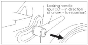
Figure 1: Locking handle for belt table |
|
|
|
It refers to the machines and not the type of abrasive finish- |
||
|
|
ing being performed. |
Using the Indexing Lock Handle |
|
|
|
Before operating your sander, please read the basic |
||
|
|
instructions on safe machine usage on the preceding two |
|
The lock handle is spring loaded and can be reposi- |
|
|
pages. |
tioned on its shaft to permit easy locking and unlocking. |
|
|
|
Belt Sander |
To Reposition the Handle: |
|
|
|
The sanding belt must be in good condition, at proper |
1. |
Pull outward against its spring. |
|
|
2. |
Rotate the handle to the position you require. |
|
|
|
tension, and tracking correctly, before doing any sanding, |
||
|
|
3. |
Release the handle and its spring will return it to the |
|
|
|
grinding or other abrasive machining operations. Refer to |
||
|
|
correct operating position. |
||
|
|
the section on Track Mechanism Maintenance if you have |
||
|
|
|
|
|
|
|
any problems with belt tension or tracking. |
Adjusting the Belt Sander Arm |
|
|
|
Adjusting the Belt Sander Table |
||
|
|
|
The arm which holds the sanding belt can be posi- |
|
|
|
You can tilt the table in a range between 20o upward |
tioned at a full vertical position, a full horizontal position, or |
|
|
|
and 45o downward. A single locking handle on the side of |
at any angle in between which is convenient to the type of |
|
|
|
the table is used to lock and unlock the table to permit |
sanding you are doing. |
|
|
|
adjustment. |
|
A positive stop mechanism is used to permit quick |
|
|
There are two positive lock stop positions: at 90o (that |
adjustment to the vertical or horizontal positions. |
|
|
|
is, at a right angle to the platen) and at 45o downward (es- |
To Adjust to Vertical: |
|
|
|
sentially 90o + 45o or 135o total to the platen.) |
||
|
|
To Tilt the Belt Sander Table: |
1. |
Unlock both of the lock bolts. These are located under |
|
|
the arbor cover. |
||
|
|
1. Unlock the locking handle on the side of the table. |
2. |
Move the arm to vertical until it contacts its stop. |
8 |
|
2. Using the pointer and scale, set the angle to any re- |
3. |
Tighten both of the lock bolts, and replace arbor cover. |
|
quired angle between 20o upward and 45o downward. |
To Adjust to Horizontal: |
||
|
|
3. Lock the lock handle. |
||
|
|
To Tilt the Table to Exactly 45o: |
1. |
Unlock both of the lock bolts. |
|
|
2. |
Move the arm to horizontal until it contacts its stop. (See |
|
|
|
1. Flip out the stop bracket (see Figure 20). |
Figure 3.) |
|
|
|
2. Unlock the locking handle. |
3. |
Tighten both of the lock bolts and replace arbor cover. |
|
|
3. Move the table until it contacts the stop bracket. |
To Adjust the Arm to Any Angle Between |
|
|
|
4. Lock the table lock handle. |
||
|
|
|
Vertical and Horizontal: |
|
|
|
|
1. |
Unlock both of the lock bolts. |
|
|
|
2. |
Use a machinist's protractor and level to set the arm to |
|
|
|
the required angle. |
|
|
|
CAUTION: NEVER ADJUST THE TABLE ANGLE |
3. |
Tighten both of the lock bolts and replace arbor cover. |
|
|
|
|
|
|
|
WHILE THE SANDER IS RUNNING. ALWAYS TURN |
|
|
|
|
THE MOTOR OFF BEFORE ADJUSTING THE TABLE |
|
|
|
|
ANGLE. |
|
|
|
|
|
|
|
|
|
|
|
|

Figure 2: Lock bolts for belt arm
Figure 3: Arm at horizontal -- note that the table is removed. The table may be removed or left in position, and may also be set to any angle to allow horizontal sanding of various angles.
CAUTION: NEVER ADJUST THE ARM ANGLE WHILE THE SANDER IS RUNNING. ALWAYS TURN OFF THE MOTOR BEFORE ADJUSTING THE ARM ANGLE.
Figure 4: Disc sander table adjustment
Adjusting the Disc Sander Table
1.Unlock the two locking knobs underneath the table at each end. (See Figure 4.)
2.Using the pointer and scale, set the angle to any required angle between 20o upward and 45o downward.
3.Lock the two locking knobs underneath the table.
CAUTION: NEVER ADJUST THE TABLE ANGLE WHILE THE SANDER IS RUNNING. ALWAYS TURN THE MOTOR OFF BEFORE ADJUSTING THE TABLE ANGLE.
Use of the Miter Gauge
The miter gauge can be used on either the disc or belt surfaces to sand accurate angles on workpieces. When using the gauge, alone, you sand a single angle. However, by tilting the table and using the miter gauge in combination with the table tilt, it is possible to sand compound angles, as well.
When grinding a compound angle you should always check the accuracy of your setup by sanding a piece of scrap material before doing any finish sanding on the actual workpiece.
1.Set the angle you wish to sand using the scale on the miter gauge.
2.Tighten the miter gauge securely so the miter reference surface will not move while you are sanding.
3.Place the workpiece against the miter reference surface and slide it along the reference surface and into the sanding disc or belt. The basic method is shown in Figure 5, below.
9 |
Figure 5: Use of the miter system

Maintenance
Belt Replacement
1.Disconnect the power to the machine to prevent accidental start-ups. If the machine is plugged into an outlet, unplug it. If the machine is hardwired to a branch circuit with a junction box, remove the fuse or trip the circuit breaker to the branch.
2.Remove the lock knob and top cover (See Figure 6).
3.Remove the side guard and table.
4.Release the belt tension by turning the tension handle in a counterclockwise direction (See Figure 7). If the handle is difficult to turn, perform Track Mechanism Maintenance according to the instructions following this section.
5.Remove the belt.
6.Check the drums and platen for scoring or signs of wear which might require service or replacement.
7.Check the height of the platen with a straight edge. If it is not 1/32 in. above the drums, adjust it according to the instructions in Platen Replacement or Adjustment in the
Machine Setup section of this manual.
8.Check the drums for looseness which might cause tracking problems. Correct any loose condition by tightening or replacing any parts as required.
9.Slip the new belt onto the drums and platen.
10.Adjust the tension handle clockwise until the belt is flat against the platen and there is no curling or buckling of the belt in the middle.
11.Turn the drums by hand to see if the belt tracks more- or-less true. JUST BECAUSE THE OLD BELT TRACKED CORRECTLY DOES NOT MEAN THE NEW BELT WILL. Always check the tracking when replacing a belt.
12.To adjust the tracking:
12.1.Plug the machine back into the outlet or reestablish power in the branch.
12.2.Loosen the tracking lock knob.
12.3.Jog the motor on and off as necessary to
observe the tracking, and turn the tracking knob as necessary to make the belt track in the center of the platen and drums. Turn the tracking knob clockwise to
10move the belt toward the right and counterclockwise to move the belt toward the left.
12.4.When the belt seems to be tracking correctly, turn the motor on and leave it running while fine tuning the tracking.
12.5.Lock the tracking lock knob.
12.6.When the lock knob is secure, turn the power off and disconnect the machine from the outlet or branch as in Step 1, above.
13. Replace the table, side guard, top cover and lock knob by reversing steps 3 and 2, above.
14. If you have not already done so, reconnect the power to the machine and return it to service.
Figure 6: Top cover components
Figure 7: Belt adjustment components (Note top cover removed for removal and replacement of belt.)
Loading...