


851.02.100
Operating Instructions
Betriebsanleitung
Mode d’emploi
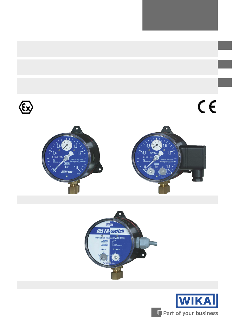
Differential pressure gauges Model 702.01.100, 702.02.100,
702.03.100 and 851.02.100 per directive 94/9/EC (ATEX)
Differenzdruckmessgeräte Typ 702.01.100, 702.02.100, 702.03.100
und 851.02.100 nach Richtlinie 94/9/EG (ATEX)
Manomètres pour pression différentielle Type 702.01.100,
702.02.100, 702.03.100 et 851.02.100 selon directive 94/9/EG (ATEX)
II 2 GD c
su
Model 702.01.100 per ATEX
st
Model 702.02/03.100 per ATEX
sv
GB
D
F
Model 851.02.100 per ATEX

GB
Operating instructions Model 702.01.100, 702.02.100,
702.03.100 and 851.02.100 per ATEX Page 1-14
Betriebsanleitung Typ 702.01.100, 702.02.100,
D
702.03.100 und 851.02.100 nach ATEX Seite 15-26
Mode d’emploi Type 702.01.100, 702.02.100,
F
702.03.100 et 851.02.100 selon ATEX Page 27-35
2 WIKA Operating instructions DELTA-plus, DELTA-comb and DELTA-switch per ATEX
11242370 06/2007 GB/D/F

Contents
Contents
Contents
1. Safety instructions 4
2. Description and operating principle 4
3. Technical data and intended use 5
4. Requirements for use in potentially explosive
atmospheres 5
5. Installation instructions 6
6. Measuring assembly 7
7. Commissioning 8
8. Optional extras / accessories 9
9. Maintenance and servicing / cleaning 11
10. Repairs 11
11. Disposal 11
Enclosure 1: Declaration of conformity
for Model 702.01.100 su 12
Enclosure 2: Declaration of conformity
for Models 702.02.100 / 702.03.100 st 13
GB
Enclosure 3: Declaration of conformity
for Model 851.02.100 sv 14
11242370 06/2007 GB/D/F
3WIKA Operating instructions DELTA-plus, DELTA-comb and DELTA-switch per ATEX
1. Safety instructions / 2. Description and operating principle
1. Safety instructions
!
GB
Caution
The appropriate national safety regulations (i.e. VDE 0100 /
EN 60 079-14 / EN 837-2) must be observed when installing,
commissioning and operating these instruments.
T Do not work on gauge while under voltage (applies to
Model 702.02/03.100 and 851.02.100)
T Serious injuries and/or damage can occur should the appropriate
regulations not be observed
T Only appropriately qualified personnel should work on these
instruments
T The effective maximum surface temperature does not depend on
these gauges themselves, but mainly on the respective medium
temperature! For maximum permissible medium temperatures,
see the table on page 6.
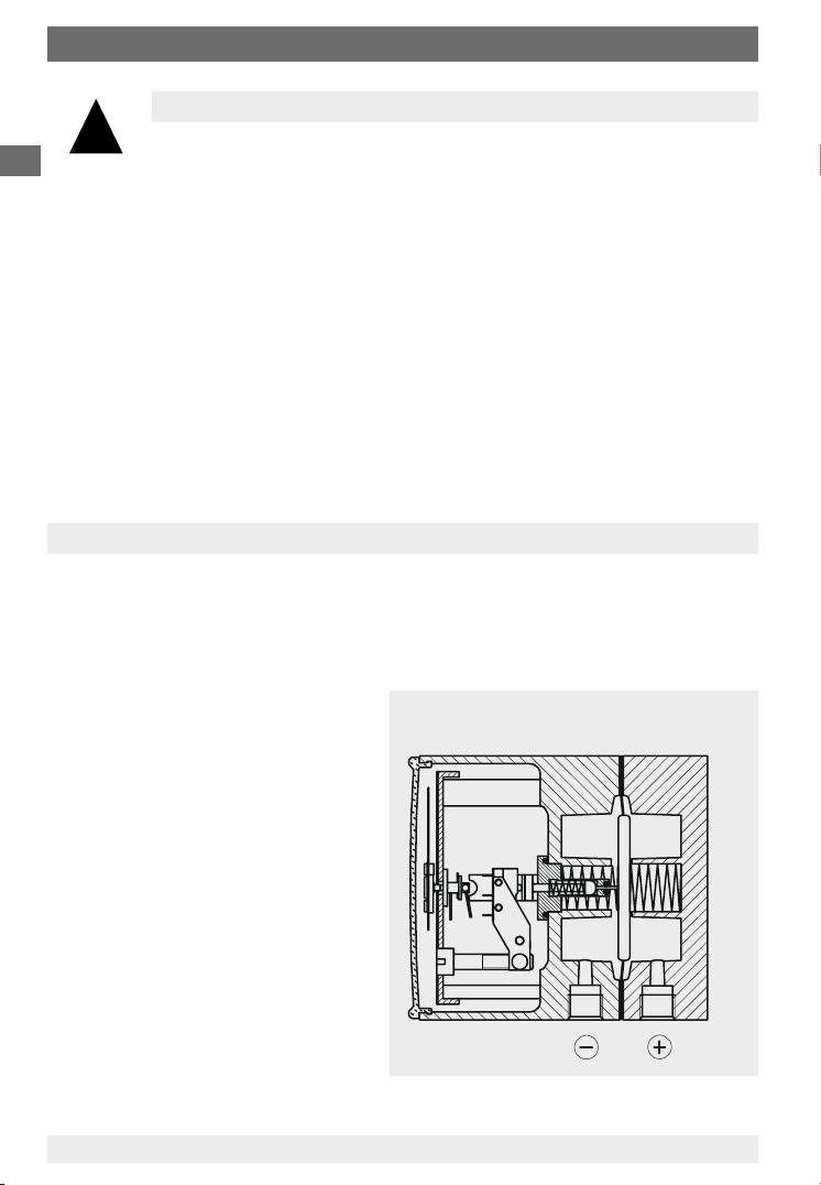
2. Description and operating principle
The j and i measuring medium chambers are separated by an elastic diaphragm. The differential pressure causes an axial movement (measured travel) in
the diaphragm against the measuring range spring. The measured travel is
proportional to the differential pressure and is transmitted, "pressure sealed"
and with minimal friction, via a connecting rod; for:
T su to the movement
T st to the movement
and in addition to the plungers
on the microswitches
T sv to the plungers
on the microswitches
For further information on gauge
construction
T su see data sheet
PM 07.15
T st see data sheet
PM 07.16 or PM 07.19
T sv see data sheet
PM 07.17
4 WIKA Operating instructions DELTA-plus, DELTA-comb and DELTA-switch per ATEX
Illustration for example st
2122740.01
11242370 06/2007 GB/D/F

3. Technical data and intended use / 4. Requirements for use ...
3. Technical data and intended use
Static pressure: 25 bar
Overpressure safety (either side): up to 25 bar max.
Operating temperature Ambient -10 … +70 °C
Observe restrictions for use in potentially explosive atmospheres
(see section 4)
Pressure connection: 2 × G ¼ female
IP Ingress protection: IP 54 (EN 60 529 / IEC 529)
Permissible vibration levels at the mounting point
T As a matter of principle the instruments should only be mounted in locations
without a vibration load.
T Isolation from a mounting point exposed to vibration can be achieved, for
example, by mounting the pressure gauge to a solid wall and a flexible
capillary connecting the measuring point to the pressure gauge (see
section 5).
T The following limits must not be exceeded:
Frequency range < 150 Hz
Acceleration < 0.7 g (7 m/s
Electrical contact
(applies to Model 702.02/03.100 and 851.02.100)
Adjustable range: from 10 % to 100 % of span
Switching point adjustment: from the outside by means of setpoint screw(s)
Contact hysterisis: max. 5 % of full-scale value
Medium +90 °C maximum
2
)
GB
4. Requirements for use in potentially explosive
!
Note
11242370 06/2007 GB/D/F
The built-in Reed contacts (applies to Model 702.02/03.100 and
851.02.100) do not possess their own ignition source. For the
purposes of intrinsic safety they are 'simple apparatus' as defined
in EN 50 020.
When supplied from a tested and certified intrinsically safe circuit
(associated apparatus), these switches may be used in potentially
explosive atmospheres up to category 2 without having to take any
further measures.
atmospheres
5WIKA Operating instructions DELTA-plus, DELTA-comb and DELTA-switch per ATEX

4. Requirements for use ... / 5. Installation instructions
Operating temperature for all Models
Ambient (for use in potentially explosive atmospheres): -10 ... +60 °C
GB
Medium: The permissible medium temperature does not only depend on
the instrument design, but also on the ignition temperature of the
surrounding explosive atmosphere. Both aspects have to be
taken into account.
For permissible maximum medium temperatures see table
Attention! With gaseous substances the temperature may increase as a result
of the compression temperature. In such cases, either the rate of change of the
pressure must be slowed down or the permissible medium temperature must be
reduced.
Permissible medium temperature
Temperature class of Permissible maximum medium
the ambient atmosphere temperature (in the pressure system)
(ignition temperature)
T 6 ( > 85 °C) +70 °C
T 5 ( > 100 °C) +85 °C
all other temperature classes +90 °C
5. Installation instructions
Installation of the differential pressure gauge should follow the installation
recommendations for pressure gauges according to EN 837-2 /7.
T The maximum permissible medium / ambient temperature must not be
exceeded
T Prior to the installation of the pressure gauge, the pipes should be thoroughly
cleaned by tapping, blowing or rinsing
T The pressure gauges must be protected against contamination and high
temperature fluctuations!
T The pressure gauges should be installed and operated so as to avoid
exposure to vibration (see also section 3: Permissible vibration levels at the
mounting point).
6 WIKA Operating instructions DELTA-plus, DELTA-comb and DELTA-switch per ATEX
11242370 06/2007 GB/D/F
5. Installation instructions / 6. Measuring assembly
Wall mounting
Installation using the three integral, cast mounting brackets
6. Measuring assembly
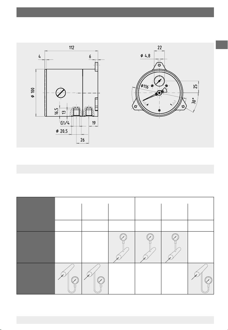
Proven measuring assemblies for various types of media. Recommended
set-up for pressure measurement instruments are shown below.
GB
2123541.01
Contents of
tail pipe
Typically
Pressure
instrument
higher
than tapping
point
Pressure
instrument
lower
than tapping
point
11242370 06/2007 GB/D/F
Liquid media Gaseous media
Liquid Liquid with Vapour Gas only Wet gas Liquid gas
vapour only condensate
Condensate Boiling liquid LPG Dry air Moist air Steam
Flue gas
7WIKA Operating instructions DELTA-plus, DELTA-comb and DELTA-switch per ATEX
7. Commissioning
7. Commissioning
7.1 Mounting of the pressure connection
GB
Pressure entries identified j and
During the commissioning process, pressure peaks must be avoided absolutely.
Open the shut-off valves slowly.
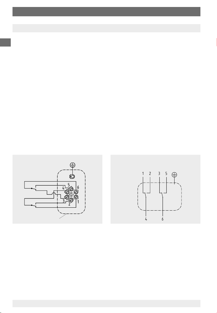
7.2 Wiring details
(applies to Model 702.02/03.100 and 851.02.100)
T The electrical connections should be made by qualified electricians
T Connection details and switch functions are given on the instrument rating
plate. Connection terminals (1 ... 6) and the ground terminal are appropriately
marked.
T The mains connection lines to be provided must be suitable for maximum
instrument power consumption and comply with IEC 227 or IEC 245
T The instruments must be included in the equipotential bonding of the plant
Connection details
ij
high pressure
i
low pressure
Connection is via a
terminal box or L-plug
per DIN 43 651
850.33 2nd contact
850.3 1st contact
Terminal box
Connection is via a
cable gland and cable
2162679.01
850.3
1nd contact
850.33
2st contact
Setting the switch point
The switch points are set by means of the setpoint screws, accessible from the
front. The 270 p° assistant scale indicates the current setpoint.
For contact re-adjustment, lever the window out of the case via the recess in its
circumference. The desired switch point can be set by turning the setpoint
screw.
Afterwards press the window back into the case.
8 WIKA Operating instructions DELTA-plus, DELTA-comb and DELTA-switch per ATEX
2162679.0X
11242370 06/2007 GB/D/F
8. Optional extras / accessories
8. Optional extras / accessories
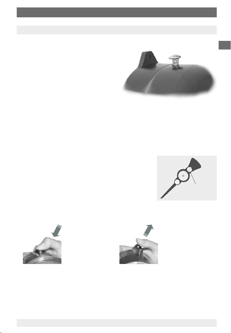
8.1 Integrated pressure equalising valve
The zero point check during operation
is enabled by pushing the valve
button.
The measuring medium flows
from the higher pressure side to the
opposite side and the differential
pressure drops to zero.
st and sv:
When the valve button is pushed, the differential pressure pointer must move
into the range of the zero point tolerance bar. If it does, the instrument is
functioning correctly. In the case of possible deviations beyond the tolerance
bar, a zero point correction can be made via a standard integrated adjustment
pointer.
To do this, the snap-fit window must be lifted
off using a screw driver at the impression/recess
in the circumference.
The zero point is corrected by turning the slotted
screw on the adjustment pointer.
Afterwards the window must be snap-fitted back
Slotted
screw
onto the case. The differential pressure is indicated
once more, as soon as the valve button is released.
GB
11242370 06/2007 GB/D/F
Valve button,
pushed
Differential pressure
is zero
Released
Differential pressure
is measured again
9WIKA Operating instructions DELTA-plus, DELTA-comb and DELTA-switch per ATEX
8. Optional extras / accessories
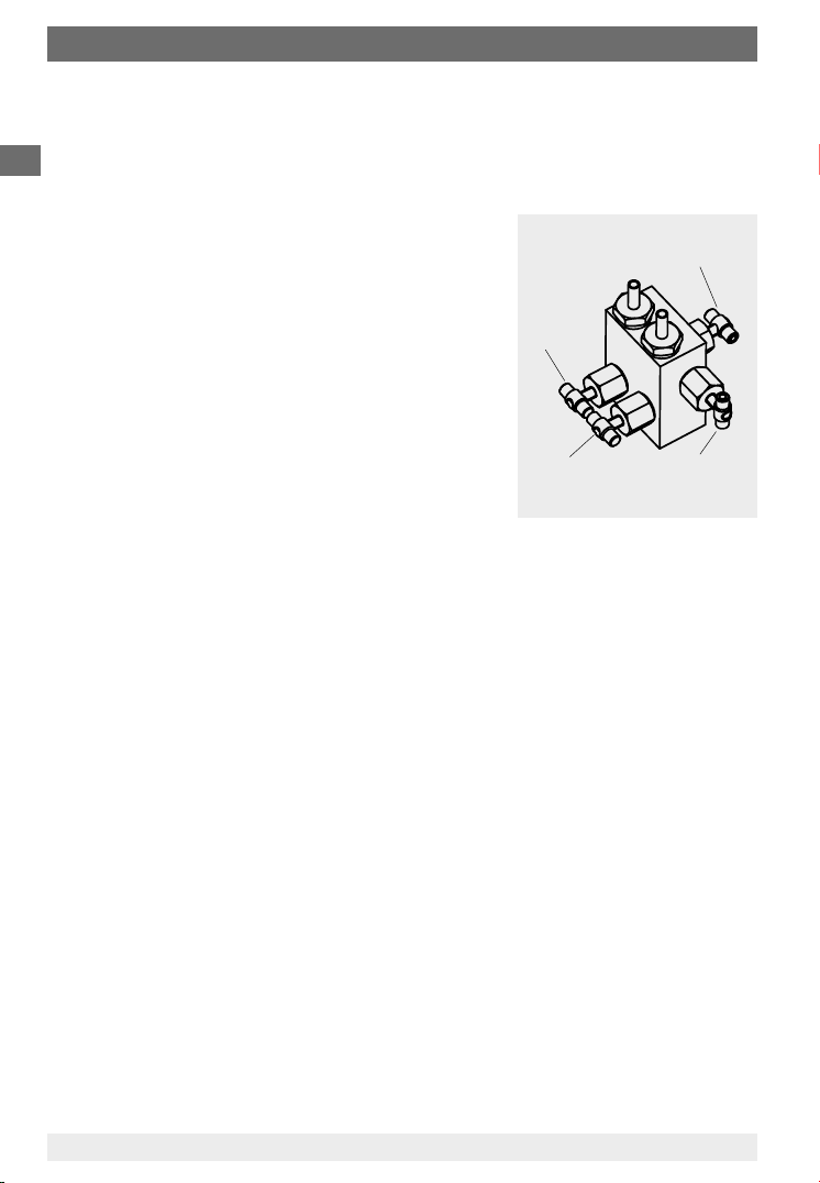
8.2 Four-way valve manifold
T Shut off j - and i process line for disassembling and testing of
GB
measuring instrument without interrupting the process that is running.
Protect the instrument against inadmissible
overpressure loading, such as, for example,
in the case of pressure tests and undefined
operating conditions (also temporary shut
down).
Gauge valve,
T Pressure equalising for zero point check
during normal operation as well as equali-
high pressure
j
side
sation of the pressures at high pressure and
low pressure side during start-up and operation
(with opened pressure equalising valve).
T Process line air bleeding for liquid measuring
media and purging the process line for
removing impurities.
Gauge valve,
low pressure
side
8.2.1 Handling instructions
T Work sequence to start measuring
1. Open pressure equalising valve (middle valve)
2. Open shut-off valve of the negative-pressure media chamber (i right
valve) and the positive-pressure media chamber (j left valve)
3. Close pressure equalising valve
T Operating sequence for air bleeding/purging of piping
1. start: Open shut-off valve of the negative-pressure (i) and positive-
pressure (j) media chamber
Open pressure equalising valve and valve for purging or air bleeding
2. end: Close pressure equalising valve and valve for purging or air bleeding
T Procedure at the end of the measuring operation
(also for partial system shut-down)
1. Open pressure equalising valve
2. Close shut-off valve of the negative-pressure (i) and positive-pressure
(j) media chamber
T Task list for removing the transmitter during normal operation
1. Open pressure equalising valve
2. Close shut-off valve of the negative-pressure (i) and positive-pressure
(j) media chamber
3. Open valve for purging or air bleeding
Pressure
equalising valve
Valve for
i
purging or
air bleeding
10 WIKA Operating instructions DELTA-plus, DELTA-comb and DELTA-switch per ATEX
11242370 06/2007 GB/D/F
8. Optional extras / accessories ... 11. Disposal
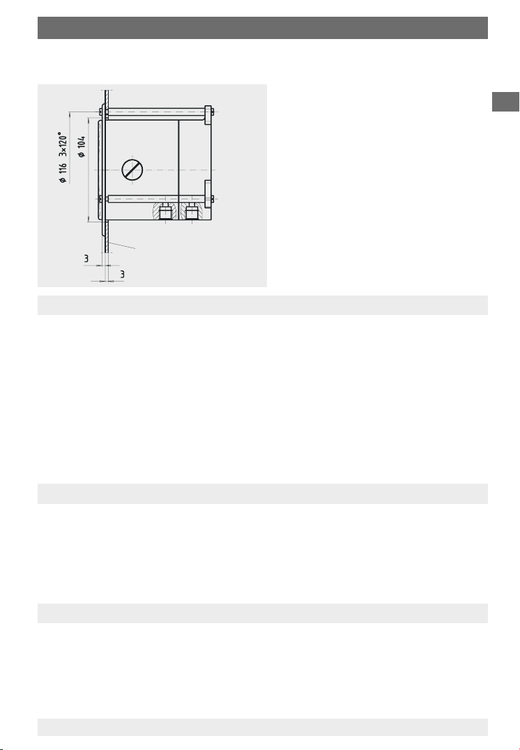
8.3 Front flange for panel mounting
2123649.0X
Panel cut-out
Panel
9. Maintenance and servicing / cleaning
The instruments require no maintenance or servicing and will give very long
service when handled and operated properly.
The indicator and switching function should be checked once or twice every
12 months. The instrument must be disconnected from the process to check
with a pressure testing device.
The instruments should be cleaned with a damp cloth, moistened with soap
solution. It must be ensured that all the parts are dry before the power is
switched on again.
The residual pressure medium in dismounted pressure gauges may be
hazardous or toxic. This should be considered when handling and storing the
removed pressure gauges.
GB
10. Repairs
Repairs should only be carried out by the manufacturer or appropriately trained
personnel.
For further details see the data sheet for the respective basic gauge (PM 07.15,
PM 07.16, PM 07.17 or PM 07.19).
11. Disposal
Dispose of instrument components and packaging materials in accordance with
the respective waste treatment and disposal regulations of the region or country
to which the instrument is supplied.
11242370 06/2007 GB/D/F
11WIKA Operating instructions DELTA-plus, DELTA-comb and DELTA-switch per ATEX
 Loading...