


WHP43
Whirlpool WHP43, WHP44, WGHP43, WGHP44, WGHP46 Installation Instructions Manual
...
HEAT PUMP INSTALLATION INSTRUCTIONS
Table of Contents
HEAT PUMP SAFETY PRECAUTIONS.........................................1
Important Note to the Owner Regarding Product Warranty .......2
Shipping Inspection .....................................................................2
Codes and Regulations................................................................2
Installation Clearances................................................................. 2
Rooftop Installations ....................................................................3
SAFE REFRIGERANT HANDLING ................................................3
REFRIGERANT LINES....................................................................4
Burying Refrigerant Lines.............................................................5
Refrigerant Line Connections ......................................................5
Leak Testing—Nitrogen or Nitrogen-Traced ...............................5
System Evacuation ......................................................................5
HEAT PUMP SAFETY PRECAUTIONS
The following symbols and labels are used throughout this manual to indicate immediate or potential safety hazards. It is the owner’s
and installer’s responsibility to read and comply with all safety information and instructions accompanying these symbols. Failure to
heed safety information increases the risk of personal injury, property damage, and/or product damage.
ELECTRICAL CONNECTIONS ......................................................6
Over-current Protection ...............................................................6
High Voltage Connections ...........................................................6
Low Voltage Connections ............................................................6
SYSTEM START-UP.......................................................................8
FINAL CHARGE ADJUSTMENT....................................................8
Fixed Orifice .................................................................................9
Expansion Valve System..............................................................9
2-Stage Application......................................................................9
Heat Pump—Heating Cycle.......................................................10
TROUBLESHOOTING INFORMATION .......................................11
ASSISTANCE OR SERVICE.........................................................16
Recognize this symbol as a safety precaution.
WARNING
Hazards or unsafe practices could result in property
damage, product damage, severe personal injury or death.
Goodman 1
CAUTION
Hazards or unsafe practices may result in property
damage, product damage, personal injury or death.
Goodman 6
Disconnect ALL power before servicing.
Multiple power sources may be present.
Failure to do so may cause property damage,
personal injury or death.
WARNING
HIGH VOLTAGE!
WARNING
Installation and repair of this unit should
CAUTION
Goodman 9
Hazards or unsafe practices may result in property
or product damage.
be performed ONLY by individuals meeting
the requirements of an “Entry Level Technician,”
at a minimum, as specified by the Air-Conditioning,
Heating and Refrigeration Institute (AHRI). Attempting
to install or repair this unit without such background may
result in product damage, personal injury or death.
Goodman 7
CAUTION
Scroll equipped units should never be used to evacuate
Placeholder
for Bar
the air conditioning system. Vacuums this low can cause
internal electrical arcing resulting in a damaged or failed
compressor.
Code
Whirlpool® and Whirlpool Gold® Models WHP43, WHP44, WGHP43, WGHP44, WGHP46, WGHP48
WPIO-259L
Goodman 32
Important Note to the Owner Regarding
Product Warranty
Your warranty certificate is supplied as a separate document with
the unit installed by your contractor. Read the limited warranty
certificate carefully to determine what is and is not covered. Keep
the warranty certificate in a safe place. If you are unable to locate
the warranty certificate, please contact your installing contractor,
or contact customer service at 1-866-944-7575 to obtain a copy.
To receive the 10-Year Parts Limited Warranty, online registration
must be completed within 60 days of installation. Online
registration is not required in California or Quebec.
Product limited warranty certificates for models currently in
production can be viewed at www.whirlpoolhvac.com. If your
model is not currently in production or does not appear on the
website, please contact your installing contractor or contact
customer service at 1-866-944-7575 to obtain a copy of your
warranty certificate.
To register your unit, go to www.whirlpoolhvac.com. Click on the
manufacturer’s Comfort Commitment
the bottom center of the home page. Next, click on the Click
Here to Register Your Product link located at the top center of the
page, and complete the forms in the manner indicated.
TM
Warranty link located at
Shipping Inspection
Always keep the unit upright; laying the unit on its side or top
may cause equipment damage. Shipping damage and
subsequent investigation is the responsibility of the carrier. Verify
the model number, specifications, electrical characteristics and
accessories are correct prior to installation. The distributor or
manufacturer will not accept claims from dealers for
transportation damage or installation of incorrectly shipped units.
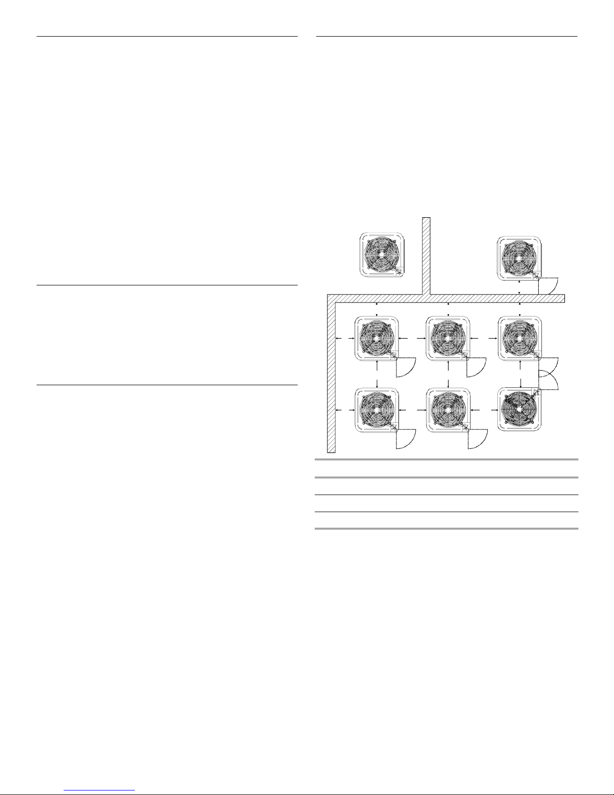
Installation Clearances
Special consideration must be given to the location of the heat
pump(s) in regard to structures, obstructions, other units and any/
all other factors that may interfere with air circulation. Where
possible, the top of the unit should be completely unobstructed;
however, if vertical conditions require placement beneath an
obstruction, there should be a minimum of 60" (152 cm) between
the top of the unit and the obstruction(s). The specified dimensions
meet requirements for air circulation only. Consult all appropriate
regulatory codes prior to determining final clearances.
Another important consideration in selecting a location for the
unit(s) is the angle to obstructions. Either side adjacent the valves
can be placed toward the structure provided the side away from
the structure maintains minimum service clearance.
NOTE: Corner installations are strongly discouraged.
Not Recommended
B
A
C
AA
B B
AA AA
C
AA
B
AA
OK!
OK!
OK!
OK!
OK!
OK!
Codes and Regulations
This product is designed and manufactured to comply with
national codes. Installation in accordance with such codes and/
or prevailing local codes/regulations is the responsibility of the
installer. The manufacturer assumes no responsibility for
equipment installed in violation of any codes or regulations.
The United States Environmental Protection Agency (EPA) has
issued various regulations regarding the introduction and
disposal of refrigerants. Failure to follow these regulations may
harm the environment and can lead to the imposition of
substantial fines. Should you have any questions please contact
the local office of the EPA.
If replacing a condensing unit or air handler, the system must be
manufacturer-approved and Air Conditioning, Heating and
Refrigeration Institute (AHRI) matched.
NOTE: Installation of unmatched systems is not allowed.
Operating the unit in a structure that is not complete (either as
part of new construction or renovation) will void the warranty.
A
AA
AA
CC
Minimum Airflow Clearance—in. (cm)
Model Type A B C AA
Residential 10 (25) 10 (25) 18 (46) 20 (51)
Light Commercial 12 (31) 12 (31) 18 (46) 24 (61)
This unit can be located at the ground floor level or on flat roofs.
At ground floor level, the unit must be on a solid, level foundation
that will not shift or settle. To reduce the possibility of sound
transmission, the foundation slab should not be in contact with or
be an integral part of the building foundation. Ensure the
foundation is sufficient to support the unit. A concrete slab raised
above ground level provides a suitable base.
2
Rooftop Installations
If it is necessary to install this unit on a roof structure, ensure the
roof structure can support the weight and that proper
consideration is given to the weather-tight integrity of the roof.
Since the unit can vibrate during operation, sound vibration
transmission should be considered when installing the unit.
Vibration absorbing pads or springs can be installed between the
unit legs or frame and the roof mounting assembly to reduce
noise vibration.
NOTE: These units require special location consideration in areas
of heavy snow accumulation and/or areas with prolonged
continuous subfreezing temperatures. Heat pump unit bases
have cutouts under the outdoor coil that permit drainage of frost
accumulation.
SAFE REFRIGERANT HANDLING
While these items will not cover every conceivable situation, they
should serve as a useful guide.
Situate the unit to permit free unobstructed drainage of the
defrost water and ice. In more severe weather locations, it is
recommended that the unit be elevated to allow unobstructed
drainage and airflow.
The following elevation minimums are recommended:
Design Temperature
+15ºF (-9ºC) and above 2¹⁄₂" (6.4 cm)
-5º (-20.6ºC) to +14º (-10ºC) 8" (20.3 cm)
below -5º (-20.6ºC) 12" (30.5 cm)
Suggested Minimum Elevation
WARNING
WARNING
To avoid possible injury, explosion or death, practice safe
handling of refrigerants.
Goodman 12
WARNING
Refrigerants are heavier than air. They can “push out”
the oxygen in your lungs or in any enclosed space. To
avoid possible difficulty in breathing or death:
• Never purge refrigerant into an enclosed room or
space. By law, all refrigerants must be reclaimed.
• If an indoor leak is suspected, throughly ventilate the
area before beginning work.
• Liquid refrigerant can be very cold. To avoid possible
frostbite or blindness, avoid contact and wear gloves
and goggles. If liquid refrigerant does contact your
skin or eyes, seek medical help immediately.
• Always follow EPA regulations. Never burn refrigerant,
as poisonous gas will be produced.
Goodman 13
To avoid possible explosion:
• Never apply flame or steam to a refrigerant cylinder. If
you must heat a cylinder for faster charging, partially
immerse it in warm water.
• Never fill a cylinder more than 80% full of liquid
refrigerant.
• Never add anything other than R-22 to an R-22 cylinder
or R-410A to an R-410A cylinder. The service
equipment used must be listed or certified for the type
of refrigerant used.
• Store cylinders in a cool, dry place. Never use a cylinder
as a platform or a roller.
Goodman 14
WARNING
To avoid possible explosion, use only returnable (not
disposable) service cylinders when removing refrigerant
from a system.
• Ensure the cylinder is free of damage which could lead
to a leak or explosion.
• Ensure the hydrostatic test date does not exceed 5 years.
• Ensure the pressure rating meets or exceeds 400 lbs.
When in doubt, do not use cylinder.
Goodman 15
3
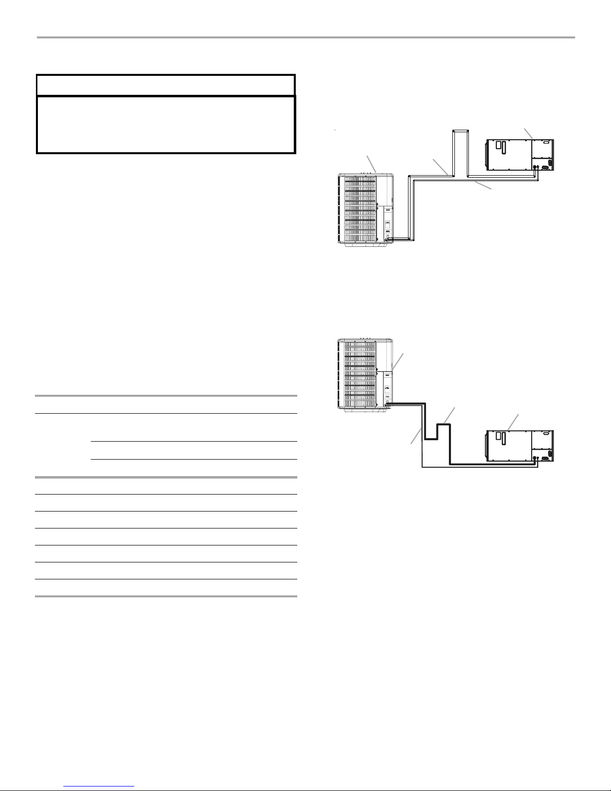
REFRIGERANT LINES
CAUTION
The compressor POE oil for R-410A units is extremely
susceptible to moisture absorption and could cause
compressor failure. Do not leave system open to
atmosphere any longer than necessary for installation.
Use only refrigerant-grade (dehydrated and sealed) copper
tubing to connect the heat pump with the indoor evaporator. After
cutting the tubing, install plugs to keep refrigerant tubing clean
and dry prior to and during installation. Tubing should always be
cut square, keeping the ends round and free from burrs. Clean
the tubing to prevent contamination.
NOTE: Do not let the refrigerant lines come in direct contact with
plumbing, ductwork, floor joists, wall studs, floors and walls.
When running refrigerant lines through a foundation or wall,
openings should allow for sound and vibration absorbing material
to be placed or installed between tubing and foundation. Any gap
between the foundation or wall and refrigerant lines should be
filled with a pliable silicon-based caulk, RTV or a vibration
damping material. Avoid suspending refrigerant tubing from joists
and studs with rigid wire or straps that would come in contact
with the tubing. Use an insulated or suspension-type hanger.
Keep both lines separate and always insulate the suction line.
These sizes are recommended for line lengths of 79 ft (24 m) or
less to obtain optimum performance. For alternate line sizing
options or runs of more than 79 ft (24 m), refer to Remote Cooling
Service Manual, TP-107 Long Line Set Application R- 410A or
contact your distributor for assistance.
Goodman 16
Mounting the evaporator coil above the heat pump will require an
inverted loop in the suction line adjacent or near the connection
to the evaporator coil. The top of the loop must be slightly higher
than the top of the evaporator coil.
C
A
A. Heat pump
B. Suction line
Mounting the heat pump above the evaporator coil will require an
oil trap in the suction line. Install one oil trap at the evaporator for
a height difference of more than 15 ft (4.5 m) between indoor and
outdoor units.
B
D
C. Evaporator coil
D. Liquid line
A
Recommended Interconnecting Tubing—ft (m)
0 to 24
(7)
25 to 49
(8 to 15)
50 to 79
(15 to 24)*
Conditioner Line Diameter (in. OD)
Unit Tons Suction Liquid Suction Liquid Suction Liquid
1¹⁄₂ ⁵⁄₈ ¹⁄₄ ³⁄₄ ³⁄₈ ³⁄₄ ³⁄₈
2 ⁵⁄₈ ¹⁄₄ ³⁄₄ ³⁄₈ ³⁄₄ ³⁄₈
2¹⁄₂ ⁵⁄₈ ¹⁄₄ ³⁄₄ ³⁄₈ ⁷⁄₈ ³⁄₈
3 ³⁄₄ ³⁄₈ ⁷⁄₈ ³⁄₈ 1¹⁄₈ ³⁄₈
3¹⁄₂ ⁷⁄₈ ³⁄₈ 1¹⁄₈ ³⁄₈ 1¹⁄₈ ³⁄₈
4 ⁷⁄₈ ³⁄₈ 1¹⁄₈ ³⁄₈ 1¹⁄₈ ³⁄₈
5 ⁷⁄₈ ³⁄₈ 1¹⁄₈ ³⁄₈ 1¹⁄₈ ³⁄₈
*For lines greater than 79 ft (24 m) in length or vertical elevation
changes more than 50 ft (15 m), refer to the Remote Cooling
Service Manual or contact your distributor for assistance.
C
B
A. Heat pump
B. Liquid line
Insulation is necessary to avoid condensation from forming and
dropping from the suction line. Armaflex (or satisfactory
equivalent) with ³⁄₈" (1 cm) minimum wall thickness is
recommended. In severe conditions (hot, high humidity areas),
¹⁄₂" (1.3 cm) insulation may be required. Insulation must be
installed in a manner which keeps tubing from damage and
contamination.
Where possible, drain as much residual compressor oil from
existing systems, lines and traps; pay close attention to low areas
where oil may collect.
NOTE: If changing refrigerant types, ensure the indoor coil and
metering device is compatible with the type of refrigerant being
used; otherwise, the indoor coil must be replaced.
C. Suction line
D. Evaporator coil
D
4
Burying Refrigerant Lines
If burying refrigerant lines cannot be avoided, use the following
checklist.
1. Insulate liquid and suction lines separately.
2. Enclose all underground portions of the refrigerant lines in
waterproof material (conduit or pipe) sealing the ends where
tubing enters/exits the enclosure.
3. If the lines must pass under or through a concrete slab,
ensure lines are adequately protected and sealed.
Leak Testing—Nitrogen or Nitrogen-Traced
WARNING
Goodman 17
To avoid the risk of fire or explosion, never use oxygen,
high pressure air or flammable gases for leak testing of a
refrigeration system.
Refrigerant Line Connections
IMPORTANT: To avoid overheating the service valve, TXV valve
or filter dryer while brazing, wrap the component with a wet rag,
or use a thermal heat trap compound. Be sure to follow the
manufacturer’s instruction when using the heat trap compound.
NOTE: Remove Schrader valves from service valves before
brazing tubes to the valves. Use a brazing alloy of 2% minimum
silver content. Do not use flux.
Torch heat required to braze tubes of various sizes is proportional
to the size of the tube. Tubes of smaller size require less heat to
bring the tube to brazing temperature before adding brazing alloy.
Applying too much heat to any tube can melt the tube. Service
personnel must use the appropriate heat level for the size of the
tube being brazed.
NOTE: The use of a heat shield when brazing is recommended to
avoid burning the serial plate or the finish on the unit.
1.
The ends of the refrigerant lines must be cut square, deburred,
cleaned and be round and free from nicks or dents. Any other
condition increases the chance of a refrigerant leak.
2. “Sweep” the refrigerant line with nitrogen or inert gas during
brazing to prevent the formation of copper-oxide inside the
refrigerant lines. The POE oils used in R-410A applications
will clean any copper-oxide present from the inside of the
refrigerant lines and spread it throughout the system. This
may cause a blockage or failure of the metering device.
3. After brazing, quench the joints with water or a wet cloth to
prevent overheating of the service valve.
4. Ensure the filter dryer paint finish is intact after brazing. If the
paint of the steel filter dryer has been burned or chipped,
repaint or treat with a rust preventive. This is especially
important on suction line filter dryers which are continually
wet when the unit is operating.
NOTES:
■ Be careful not to kink or dent refrigerant lines. Kinked or
dented lines will cause poor performance or compressor
damage.
■ Do not make final refrigerant line connection until plugs are
removed from refrigerant tubing.
■ Before brazing, verify indoor piston size by checking the
piston kit chart packaged with indoor unit.
WARNING
To avoid possible explosion, the line from the nitrogen
cylinder must include a pressure regulator and a pressure
relief valve. The pressure relief valve must be set to open at
no more than 150 psig.
Pressure test the system using dry nitrogen and soapy water to
locate leaks. If you wish to use a leak detector, charge the system
to 10 psi using the appropriate refrigerant, and then use nitrogen
to finish charging the system to working pressure. Apply the
detector to suspect areas. If leaks are found, repair them. After
repair, repeat the pressure test. If no leaks exist, proceed to
system evacuation.
Condensing unit liquid and suction valves are closed to contain
the charge within the unit. The unit is shipped with the valve
stems closed and caps installed.
NOTE: Do not open valves until the system is evacuated.
Goodman 18
System Evacuation
WARNING
REFRIGERANT UNDER PRESSURE!
Failure to follow proper procedures may cause property
damage, personal injury or death.
NOTE: Scroll compressors should never be used to evacuate or
pump down a heat pump or air conditioning system.
Goodman 19
CAUTION
Prolonged operation at suction pressures less than
20 psig for more than 5 seconds will result in overheating
of the scrolls and permanent damage to the scroll tips,
drive bearings and internal seal.
1. Connect the vacuum pump with 250 micron capability to the
service valves.
2. Evacuate the system to 250 microns or less using suction
and liquid service valves. Using both valves is necessary as
some compressors create a mechanical seal separating the
sides of the system.
3. Close pump valve and hold vacuum for 10 minutes. Typically
pressure will rise during this period.
Goodman 20
5
 Loading...