

Page 1
No. Parte W10235308 Rev. B STM02621 Rev. B
48
ESTUFAS A GAS 30”
Instructivo de Instalación, Uso y
Cuidado
30” FS GAS RANGE
Installation, Use and Care guide
Ampara los siguientes modelos:
Covers the next models:
WF5905
WF7000
WF7008
WF7010
WF9600
SWF7000
Page 2
ÍNDICE
Bienvenida . . . . . . . 3
Partes y características . . . . . 4
Instalación . . . . . . . 6
Conexión . . . . . . . 7
Verificación de funcionamiento . . . . 8
Ajuste de flamas . . . . . . 11
Uso de los accesorios y características . . . 15
Cuidado de la estufa . . . . . 20
Diagramas eléctricos . . . . . 22
Póliza de garantía . . . . . . 24
Formato de identificación . . . . . 24
Ayuda o servicio técnico . . . . . 26
TABLE OF CONTENTS
Welcome . . . . . . . 27
Parts and features . . . . . . 28
Installation . . . . . . . 30
Connection . . . . . . . 31
Verify operation . . . . . . 32
Flame adjustment . . . . . . 34
Use of features and accessories . . . . 38
Range care . . . . . . . 43
Electric diagrams . . . . . . 45
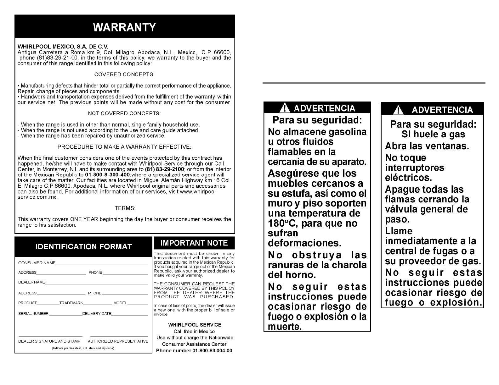
Warranty . . . . . . . 46
Identification format . . . . . 46
Assistance or service . . . . . 48
2
47
Page 3
¡Felicidades por la compra de su nueva estufa!
Acaba de adquirir un producto desarrollado con las más avanzadas técnicas
de diseño y fabricación.
Le sugerimos que antes de usar su estufa lea cuidadosamente las
instrucciones de este manual. Consérvelo, ya que la información contenida en
el mismo será importante para el buen funcionamiento de su estufa durante
muchos años.
46
3
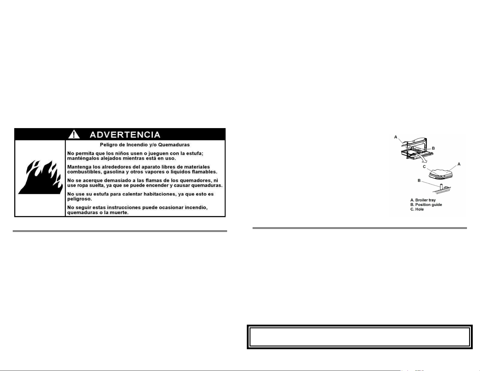
Page 4
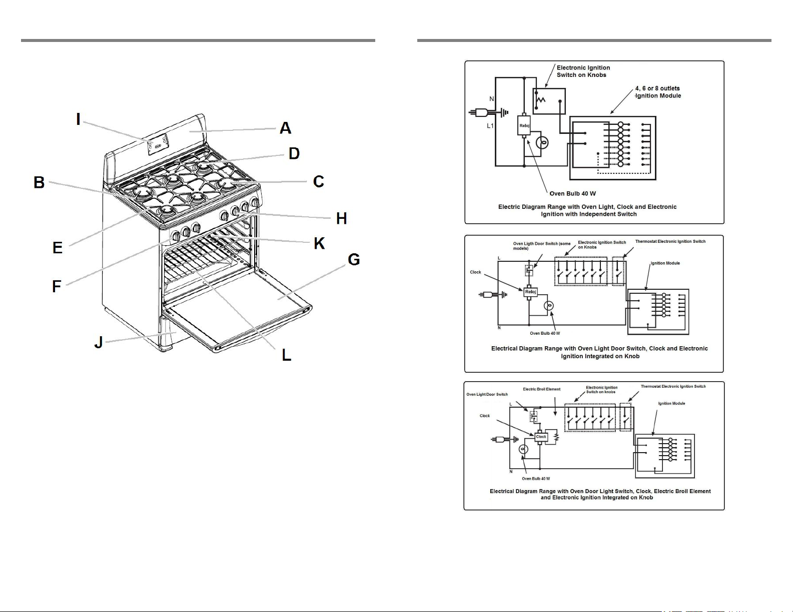
PARTES Y CARACTERÍSTICAS
ELECTRIC DIAGRAMS
A. Respaldo
B. Parrillas superiores
C. Quemadores súper
D. Quemadores estándar
E. Encendido electrónico para
quemadores superiores
F. Perillas
4
G. Puerta de horno con
ventana extra grande
H. Termostato controlado por
perilla
I. Reloj y temporizador
J. Cavidad para asar
K. Luz en el horno.
L. Parrillas deslizables
PRODUCT MANUFACTURED BY:
Industrias Acros Whirlpool S.A. de C.V., Unidad Celaya
Carretera Panamericana Km. 280 C.P. 38020, Celaya, GTO
Phone: 01 (461) 6 18 55 00
45
Page 5
Surface burners
A. Incorrect
To keep the surface burners in food conditions, some
periodical cleaning is needed. Follow these steps to do it:
1. Remove the surface grates.
2. Take off the cap and the burner, wash them with soapy
water and rinse them thoroughly. Let them dry
completely.
3. Replace the surface burners on their original position
and place the caps, making sure the alignment pins are
properly aligned with the burner cap.
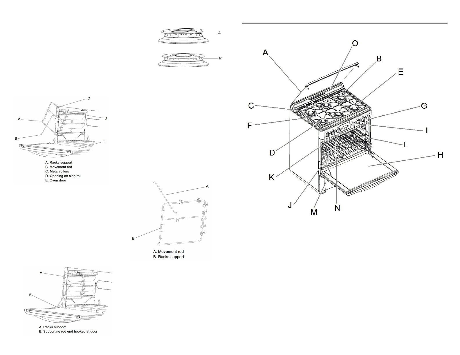
Auto-slide out oven racks
If the range has auto-slide out oven racks,
they can be removed completely together
with the side supports and can be cleaned
easily. Follow the steps on next page to
remove them and replace them:
1. Open the oven door and remove the
2. Release the end of the movement rod
3. Slide out, one at a time, the racks
4. Remove the movement rod from the rack
supports. Identify which support is right side
and which support is left side.
5. When the supports need to be placed again,
insert the movement rod on the racks
support.
6. Install, one at a time, the racks support
passing the metal rollers through the opening
on the side rail and push it back.
7. Pull the movement rods until their end
8. Place the oven racks on the desired
44
B. Correct
oven racks, the racks supports can be
removed separately.
that is hooked on the oven door.
supports passing the metal rollers
through the opening on the side rail.
can be hooked on the oven door.
level beginning with the rear edge and
finishing with the front edge. Close the
oven door.
PARTES Y CARACTERÍSTICAS
A. Capelo
B. Parrillas superiores
C. Quemadores súper
D. Quemadores estándar
E. Quemador “Multiflame
(algunos modelos)
F. Encendido electrónico para
quemadores superiores
G. Perillas
H. Puerta de horno con
ventana extra grande
I. Termostato controlado por
perilla
3
”
J. Parrillas de horno auto-
deslizables
K. Reloj y temporizador, con
control de asador (algunos
modelos)
L. Asador eléctrico alto
(algunos modelos)
M. Cavidad para asar
(modelos sin asador
eléctrico alto)
N. Luz en el horno
O. Válvula de corte de gas
(algunos modelos)
5
Page 6
Características eléctricas nominales para modelos SIN asador eléctrico
Voltaje: 127 V ~ ± 10% Frecuencia: 50/60 Hz Corriente: 1,0 A Max
Características eléctricas nominales para modelos CON asador eléctrico
Voltaje: 127 V ~ ± 10% Frecuencia: 50/60 Hz Corriente: 15,0 A Max
Recomendaciones:
• Instale su estufa en un lugar protegido de las inclemencias del tiempo y sobre una
superficie plana y resistente para soportar su peso.
• No instale su estufa sobre alfombra o algún material inflamable. Si el piso es
sintético, verifique que éste material soporte una temperatura de al menos 95°C
sin deformarse.
• No permita que la usen niños o personas que no conozcan su funcionamiento.
• Proporciónele el mantenimiento adecuado.
• Utilice la estufa sólo en labores del hogar. No es un aparato de uso comercial.
6. To cancel the function press the ADJUST pads until the OFF word is shown in
the display. Another option for cancelling is to press the BROIL pad while in the
display is shown the function, the remaining time will appear; press again the
BROIL pad to enter the “time set up” function and press again the BROIL pad
until the display shows 0:00, meaning with this that the function has been
cancelled.
The BROIL function can be protected from an unwanted start or program changes. After
the broil function has been defined, press the CLOCK pad for more than 3 seconds.
This is the “Lock” set and allows the function to finish the cycle without interruptions. To
unlock the control, press again the CLOCK pad for more than 3 seconds.
Lower drawer (models WITH electric broil element)
When the range is equipped with an electric broil element, the lower cavity will be
available only for keeping accessories and these must be taken out before using the
oven.
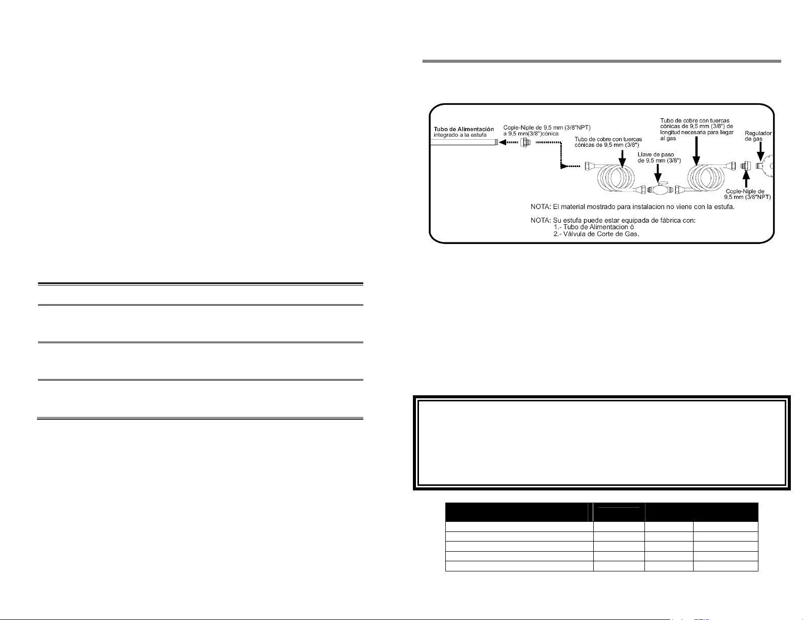
Lower broiler (models WITHOUT electric broil element)
When your range DOES NOT HAS an electric broil
element, it will be equipped with broiler below the
oven door. Before using it, place the broiler tray on
the 2 pins, as shown in the pictures.
For the broil feature to work, the oven burner should
be turned on according to the instructions on “Verify
operation”, “Oven burner” section.
When the oven burner is lit, turn the “Oven control”
knob to its maximum flame position which is 235°C
for ranges with electronic ignition thermostat or
260°C for ranges with manual ignition thermostat.
INSTALACIÓN
• La instalación apropiada es su responsabilidad, por lo cual es recomendable que
sea realizada por un técnico calificado o un técnico de Whirlpool Service.
• Retire todos los elementos de empaque y coloque los accesorios de la estufa.
• Seleccione la mejor ubicación para su estufa, no debe quedar expuesta a
corrientes de aire y debe tener espacio suficiente para abrir la puerta del horno.
• No instale gabinetes o muebles de cocina encima de la estufa.
• Si instala campana extractora, colóquela a 61 cm como mínimo desde la cubierta
de la estufa.
• Si su estufa cuenta con accesorios eléctricos, colóquela cerca de un tomacorriente
de pared.
• Esta estufa de gas está equipada con un enchufe de tres puntas con contacto a
tierra para protección contra riesgo de electrocución. Debe enchufarse
directamente a un tomacorriente debidamente aterrizado.
• No corte ni quite la punta para conexión a tierra del enchufe. No utilice
extensiones eléctricas o contactos múltiples.
6
RANGE CARE
To keep the range in good performance conditions, it is needed to conduct cleaning
procedures using water, soap and a soft cloth or sponge. Do not use wire fiber as it
could permanently scratch the enamel of the range.
Before cleaning the range, make sure all knobs are off and unplug the power cord from
the electrical wall outlet. Assure the oven and cooktop are cool.
On a regular basis, clean the gap between the manifold panel and the cooktop. The
surface grates, as well as the burners and burner caps, can be cleaned with soap and
water.
The range has the Continuous Cleaning System in the oven (rough finish inside the
oven cavity) which burns out the grease spills on the walls every time the baking feature
is used.
IMPORTANT
Do not use caustic soda or clearing agents which contain it to clean the range.
Failure on following the above will permanently damage the surface where it is applied.
43
Page 7
When the timer finalizes the cycle, the control will sound with long spaced beeps, press
any pad to stop the beeping and the display will show the time of day.
Electric broiler function (BROIL) (some models)
This function has 4 functions:
• dES – defrost
• PLA – warm dished/plates
• CAL – keep dishes warm
• GrA – browning and/or melting
• OFF – Off
The legend “End” will appear on the display when either the BROIL or TIMER functions
have ended. To program the broil function, follow these steps:
1. Open the oven door and place the oven rack on the suggested position (see
table), considering level 1 is the highest position. Place the dish over the rack
and close the oven door.
2. Push the BROIL pad, the control will show OFF on the display and the indicator
light will turn on (listed H).
3. Press the ADJUST pads to select one of the 4 functions.
4. When the function has been defined, press again the BROIL pad and proceed to
establish the time for the function (each function has a maximum programming
time, if you wish to set the function for a larger period of time, the function needs
o be set up again):
Function Food
Chicken breast (500 to 600 g)
Defrosting
Keep dishes
warm
Browning
and/or
meeting
Raw meat (400 to 500 g)
Fish scallops (350 to 450 g)
Crunch “tacos”
Poultry stews
Pasta
Melting cheese on dishes
Melting cheese on bread
Pizza
Recommended
time
2 – 2:15 hr
1 – 1:30 hr
45 min – 1hr
30 – 45 min
45 min
35 min
9 min
8 – 12 min
6 – 10 min
Oven rack
position
Level 3
Level 3
Level 3
Level 2
Level 2
Level 2
Level 3
Level 2
Level 2
5. Use the ADJUST pads to select the time and wait for 5 seconds, the function will
begin working and will be showed in the display. When the function is in
progress, the remaining time can be verified by pressing the BROIL pad.
a. IMPORTANT: Cook the meat or poultry immediately alter defrosting.
b. The function PLA allows keep dishes warm before serving them and
helps keep them warm a longer time. The dishes are adequately
heated up after 30 or 40 minutes. IMPORTANT: Do not use plastic or
carton plates, use only plates that resist high temperatures (glass,
ceramic, etc.). Use as oven racks as you need to warm all the plates
at once.
c. When using the function CAL for gravies or juicy stews, cover the dish
with aluminum foil to avoid dryness. IMPORTANT: Do not use this
function for out of the fridge dishes, as they might not warm correctly.
d. When using a function more than one time, the recommended times
might be reduced, as the oven will be preheated.
42
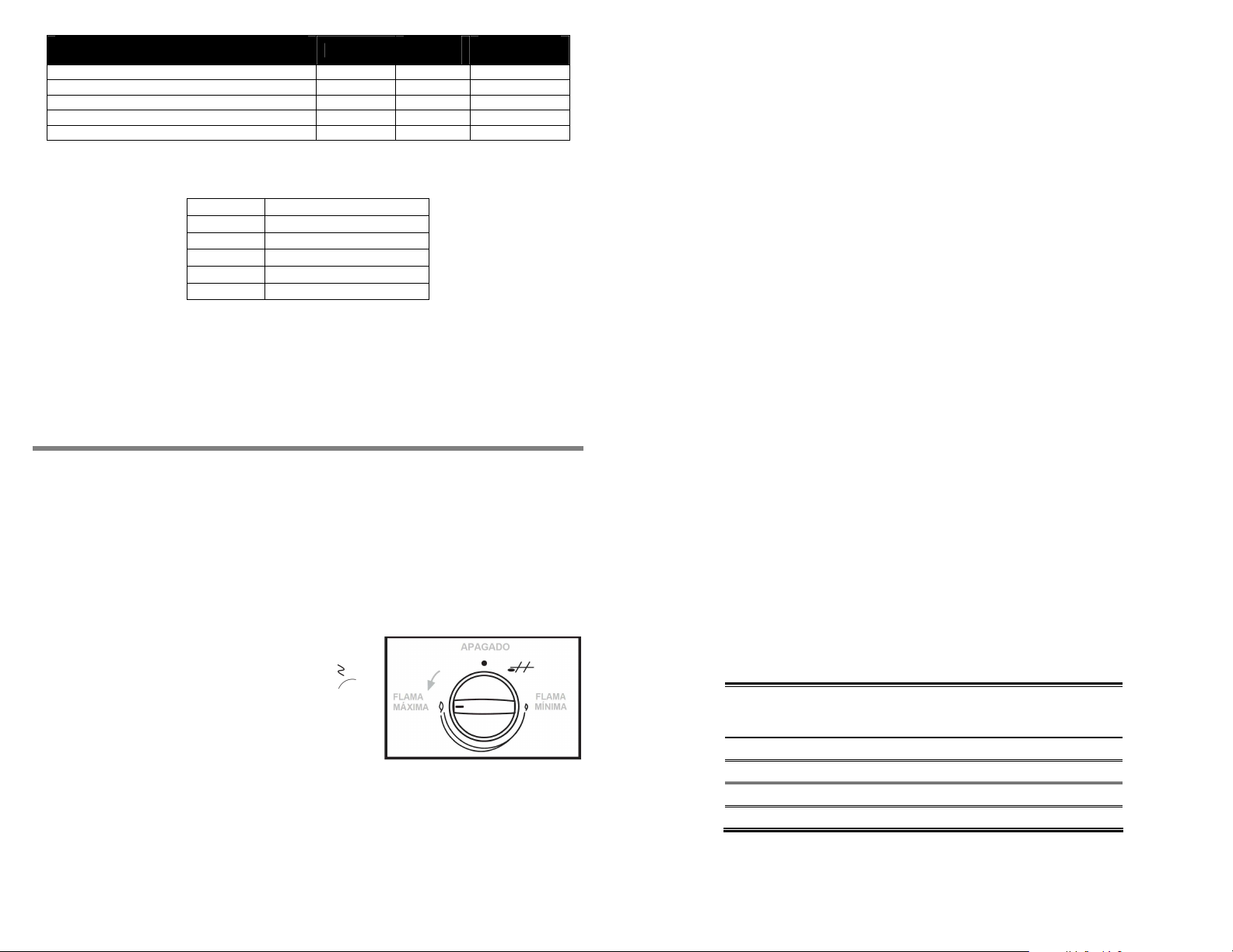
CONEXIÓN
Conexión de la estufa a la línea de gas
1. Para conectar su estufa utilice el material especificado en la figura de abajo:
2. Verifique que no existan fugas vertiendo espuma de jabón en las conexiones y
curvas de los tubos.
Recomendaciones:
• Si la instalación no es nueva, limpie los tubos para evitar que se tapen las espreas
o los pilotos.
• Con el fin de facilitar el movimiento del aparato, el instalador debe hacer una
espiral con el tubo flexible de cobre e instalar una llave de paso en la línea de
suministro de gas. Esta llave debe estar fuera de la estufa y accesible a las
personas que la usan.
IMPORTANTE
• Esta estufa está preparada para funcionar con gas L.P. de tanque móvil o
estacionario.
• Para usarse con gas Natural (tubería) debe llamar a Whirlpool Service para
cambiar las espreas y hacer los ajustes necesarios. El número telefónico aparece
en la página 26. El técnico calificado debe cerciorarse que la conexión no tiene
fugas y que la presión de gas en la estufa es la que aparece en las tablas
siguientes:
GAS LP PRESIÓN DE OPERACIÓN
2,75 kPa (28 cm Col. agua)
QUEMADOR NÚMERO mm kJ/h
SUPERIOR ESTÁNDAR ALUMINIO 78 0,78 7 000
SUPERIOR SÚPER ALUMINIO 86 0,86 7 500
SUPERIOR TRIPLE CORONA 93 0,93 10 000
HORNO 57 1,092 13 600
ESPREA
DIAM
ESPREA
CAPACIDAD
TÉRMICA
7
Page 8
GAS NATURAL PRESIÓN DE OPERACIÓN
1,76 kPa (18 cm Col. agua)
QUEMADOR NÚMERO mm kJ/h
SUPERIOR ESTÁNDAR ALUMINIO 115 1,15 7 000
SUPERIOR SÚPER ALUMINIO 118 1,18 7 500
SUPERIOR TRIPLE CORONA 133 1,33 10 000
HORNO 52 1,613 13 600
ESPREA
DIAM
ESPREA
CAPACIDAD
TÉRMICA
NOTA: Para operar esta estufa con gas natural, se requiere el juego de conversión de
acuerdo con la siguiente tabla y puede solicitarlo en su Centro de Servicio Autorizado:
Modelo Gas LP a gas Natural
WF5905 W10239488
WF7000 W10239490
WF7010 W10239490
WF7008 W10239490
WF9600 W10239492
Conexión de la estufa a la corriente eléctrica
Terminada la conexión a la línea de gas, conecte la estufa a la corriente eléctrica.
El cable tomacorriente debe conectarse a una toma de corriente con un voltaje de 127
V ~ ± 10%. Cerciórese de que la instalación está apropiadamente aterrizada.
VERIFICACIÓN DE FUNCIONAMIENTO
Ya que la estufa fue instalada es necesario verificar que la conexión de gas y eléctrica
hayan sido realizadas con éxito. Para esta actividad, coloque la estufa en su posición
final y proceda a iniciar el funcionamiento de los quemadores superiores y del horno.
The indicator light located on the left upper side of the display (listed I) will be on when
the TIMER function is working and will blink when the TIMER is programmed but the
display is showing other information (CLOCK or BROIL).
When an electrical failure occurs for less than 30 seconds, the control will return to the
set up that was running before the fail. The functions will need to be reprogrammed if
electricity takes more than 30 seconds to restore and the display will show 12:00
blinking.
Clock function (CLOCK)
The clock has a 12 hour format. To set time after plugging in the range, push any pad
and the 12:00 will stop blinking except for the colon located between the hours and
minutes. When the colon is blinking it means that is possible to set the hour. If the colon
stops flashing, push the CLOCK pad and then press one of the ADJUST buttons to
increase or decrease the time.
For a faster set up, keep one of the ADJUST pads pressed and the changing steps will
be of 5 minutes intervals; once the hour is set up, press the CLOCK pad again or wait 5
seconds, this will make the control define as valid the hour in the display.
Oven light function (LIGHT)
This function activates or turns off the oven light by pressing the LIGTH pad. If the bulb
remains turned on for more than 1 minute, the control will deactivate it automatically or
you can turn it off manually by pressing LIGHT pad again. If the bulb does not work,
replace it by following this sequence:
1. Unplug the range from the electrical wall outlet.
2. Remove the bulb twisting it counterclockwise.
3. Place a new 40 Watts bulb, designed for home appliances.
4. Plug the power cord of the range into the electrical wall outlet.
Quemadores superiores
De acuerdo con el modelo, su estufa puede tener encendido electrónico de uno o dos
pasos. Siga esta secuencia para corroborar el funcionamiento:
Para estufas con encendido electrónico de dos pasos:
1. Presione, y mantenga así, el interruptor
localizado junto a la perilla de extrema
izquierda identificado con este símbolo
gire cualquiera de las perillas de quemadores
superiores hasta la posición de flama máxima
(ver figura derecha). Escuchará el sonido de la
chispa de la bujía y se encenderá la flama,
proceda al paso 6. Si la flama no enciende o
la chispa no se oye, realice los pasos 2 al 5.
2. Retorne la perilla a la posición de apagado y suelte el interruptor.
3. Cuando la chispa no se genere, asegúrese de haber conectado el cable
tomacorriente, sin él, el interruptor y las bujías no pueden trabajar.
4. Verifique que haya suministro de gas, ya sea en el tanque o en la línea.
También revise las conexiones y tubos, podrían estar doblados o bloqueados.
8
y
Timer function (TIMER)
For setting the timer, press the TIMER pad and the indicator light will turn on; the
display will show 0:00 with the middle colon flashing, indicating with this that the timer
can be adjusted. At this moment, push any of the ADJUST buttons and introduce the
time to be counted.
The timer can be programmed with as much as 10 hours. This feature counts down the
time considering minutes and seconds, when minutes are programmed, or hours and
minutes, when hours are programmed. For example:
Time set with the
ADJUST pads
0:05 4:59 5 minutes
0:10 9:59 10 minutes
1:00 0:59 1 hour
10:00 9:59 10 hours
Time displayed
Time to be
counted
down
Once the time period has been selected, wait 5 seconds for the function to be
programmed and the colon stops flashing. If the function needs to be cancelled, push
the TIMER pad to access the “set up” function and press again the same pad to reset
the display to 0:00.
41
Page 9

2. Lift the rack from the rear edge and then from the front edge.
3. Select the new height and place the rack first on the rear and then on the front
edge.
4. Close the oven door.
Clock and timer with broiling control
(on some models)
5. Habiendo corroborado las conexiones eléctricas y de gas, presione nuevamente
el interruptor y gire la perilla a la posición de flama máxima, el quemador deberá
encenderse.
6. En cuanto la flama encienda, libere el interruptor. Esta misma secuencia puede
realizarla para los otros quemadores superiores.
7. Terminada la verificación, apague todos los quemadores.
Para estufas con encendido electrónico de un paso:
1. Gire cualquiera de las seis perillas de
quemadores superiores hasta la posición
de encendido, identificada con éste
A. Display.
B. Oven light pad.
C. Electric broiling element pad
D. Clock adjustment pad.
E. Timer adjustment pad.
F. Pad to increase temperature or time.
G. Pad to decrease temperature or time.
H. Broiling indicating light
I. Timer indication light
The range is equipped with a clock and timer that will help you keep a better control of
the cooking time as well as a button to turn on and off the oven light. In some models,
this control also includes the possibility to broil, melt or keep dished warm.
The control has a blue display and pads for each function, which depend on the range’s
model. When the range is plugged into the electrical supply the first time, a beep will
sound and all the indicators and numbers will light for a short period of time; after that,
the clock shows 12:00 blinking.
The control has sound tones that indicate what has been or is being done by the
control:
• One short beep: A pad has been pressed or a function has been introduced.
• Three beeps: An invalid pad has been pressed.
• Long and paused beeps: End of cycle for the TIMER or BROIL.
The indicator light located on the left low side of the display (listed H) will be on when
the BROIL function is working and will blink when the BROIL function is programmed
but the display is showing other information (Clock or Timer).
40
(on some models).
(on some models)
.
símbolo
Escuchará el sonido de la chispa de la
bujía y se encenderá la flama, proceda al
paso 5. Si la flama no enciende o la
chispa no se oye, continúe al paso 2.
2. Asegúrese de haber conectado el cable tomacorriente, sin él las bujías no
pueden trabajar.
3. Cuando la flama no enciende después de 5 segundos, retorne la perilla a la
posición de apagado y verifique que haya suministro de gas, ya sea en el
tanque o en la línea. También revise las conexiones y tubos, podrían estar
doblados o bloqueados.
4. Habiendo corroborado las conexiones eléctricas y de gas, gire nuevamente la
perilla a la posición de encendido.
5. Cuando la flama aparezca, mueva la perilla hasta la posición de flama máxima y
se dejará de escuchar la chispa de la bujía. Esta misma secuencia puede
realizarla para los otros quemadores superiores.
6. Terminada la verificación, apague todos los quemadores.
Aún con una interrupción de energía eléctrica, los quemadores superiores pueden
funcionar. Cuando esto suceda, realice lo siguiente:
1. Acerque un cerillo encendido al quemador que desea encender.
2. Gire la perilla de dicho quemador hasta la posición de flama máxima, la flama
deberá encenderse.
(ver figura izquierda).
Quemador de horno
Dependiendo del modelo, su estufa cuenta con un quemador de horno controlado por
un termostato con encendido manual o encendido electrónico. Si es encendido manual,
la perilla “Oven Control” tendrá temperatura máxima de 260°C. En el caso de los
modelos con encendido electrónico, la temperatura máxima de la perilla “Oven Control”
será de 235°C. Para corroborar el correcto funcionamiento, siga los siguientes pasos
dependiendo del modelo de su estufa:
Modelos con termostato de encendido manual
1. Abra la puerta del horno.
2. Encienda un cerillo y acérquelo a la entrada del quemador de horno (ver figura
siguiente página).
3. Presione y gire la perilla nombrada “Oven Control” a su posición inicial (posición
140°C).
9
Page 10

4. La flama deberá encenderse y
empezará a generar calor.
Continúe al paso 7. Si la flama no
enciende, realice los pasos 5 y 6.
5. Cuando la flama no enciende,
retorne la perilla a la posición de
apagado y verifique que haya
suministro de gas, ya sea en el
tanque o en la línea. También
revise las conexiones y tubos,
podrían estar doblados o
bloqueados.
6. Habiendo hecho esto, intente encender nuevamente el quemador con ayuda de
otro cerillo. Si tuvo éxito, continúe al paso 7, de lo contrario, retorne al paso 5.
7. Cierre la puerta de horno y abra la puerta del
asador. Observe la flama, en la parte posterior
se distingue la flama del piloto del quemador,
esta deberá tener aproximadamente 1 cm de
altura. Para ajustar la altura de la flama, revise la
sección “Ajuste de flamas”, “Flama del piloto del
quemador de horno”.
8. La flama del quemador deberá cubrir todos los
orificios y normalmente debe ser azulada y
estable; si no es así, proceda a la sección de “Ajuste de flamas”, “Flama del
quemador de horno”, “Quemador de horno con encendido manual”.
9. Habiendo verificado el quemador de horno y ajustado las flamas, gire la perilla a
la posición de apagado.
Modelos con termostato de encendido electrónico:
1. Abra la puerta del horno.
2. Retire la charola del piso de horno girando los dos sujetadores frontales y
levantando la charola por el frente. Jale hacia usted y retírela de la estufa (ver
figura superior de esta página).
3. Gire la perilla “Oven Control” en contra de las
manecillas del reloj hacia la posición de
encendido, tal como lo muestra la figura de la
derecha. En esta posición se oirá y verá la
chispa del quemador de horno. Después gírela
hasta la posición inicial (140°C). La flama
deberá encenderse y cubrir todos los orificios
del quemador. Continúe con el paso 7. Si no
se genera la chispa o la flama del quemador
no enciende, prosiga al paso 4.
4. Asegúrese de haber conectado el cable tomacorriente, sin él la bujía no puede
trabajar.
5. Si la flama no enciende, retorne la perilla a la posición de apagado y verifique
que haya suministro de gas, ya sea en el tanque o en la línea. También revise
las conexiones y tubos, podrían estar doblados o bloqueados.
6. Habiendo corroborado las conexiones eléctricas y de gas, intente nuevamente
encender el quemador girando la perilla a su posición de encendido. Si tiene
éxito, continúe al paso 7, de lo contrario, retorne al paso 4.
10
IMPORTANT
Do not obstruct the flow of combustion and ventilation air around the burner grate
edges.
Glass lid
Some models have a top glass lid. The glass lid is made of tempered glass and even
when it is resistant; it should be handled with care to avoid breakings. Open and close it
without striking it, do not let it fall down before reaching its horizontal position.
Assure that the surface burners are all turned off and cooled down before closing it and
(on some models)
never turn on the surface burners when the glass lid is down. Do not
place hot cookware on top of the glass lid.
NOTE: Surface and oven burners will not light when the glass lid is closed, this
because the range is equipped with a safety valve that cuts off the gas flow once
the glass lid is closed.
Safety valve on glass lid
The range has a safety valve which opens and closes the gas supply and is located on
the cooktop, close to the glass lid hinges.
The valve allows the gas flow only when the glass lid is open. For oven functions, the
glass lid must be open too.
(on some models)
Oven racks
Depending on the range’s model, the oven racks can be slide out manually or can be
auto-slide out when the oven door is opened.
Manual sliding oven racks
The oven cavity has 3 different heights for the racks position; these ones also have a
stop position to avoid them from falling down of the range when pulled out. To switch
the oven rack position, follow the next steps:
1. Pull the oven rack out to the stop position.
2. Raise the front edge.
3. Lift it out to release it.
4. Select the new height.
5. Place the oven rack horizontal and push it
to the stop position.
6. Raise the front edge.
7. Push again until it reaches the final
position.
Auto-slide out oven racks
Each oven rack can be placed in 5
different heights. To change the rack’s
position, follow the next steps:
1. Open the oven door, the oven racks
will slide out towards you when the
oven door is completely open.
39
Page 11

7. After adjusting the window size in the air shutter, tight the screw and place the
oven burner back in the oven cavity.
8. Replace the fastener and washer, tight them
until the oven burner is fixed.
9. Turn the oven burner back on according to
the sequence on “Verify operation”, “Oven
burner” section. If the flame is now stable and
blue, the range is ready to be used;
otherwise, wait for the burner to cool down
and repeat from step 3.
10. When the oven burner has been adjusted and
is placed inside the oven cavity, replace the
oven tray and fix again the two front brackets
on its original position. Continue with the
verification of the oven burner function.
NOTE: Do not obstruct the heat and air flow on the oven cavity; avoid covering the oven
tray grooves if aluminum foil is used.
USE OF FEATURES AND ACCESSORIES
Griddle
Among the accessories of the range, you will find a griddle. Depending on your range’s
model, it can be made of steel with enamel or aluminum with Teflon.
The enameled griddle can be placed either on top of the center burners or on top of any
of the both side burners.
For the aluminum with Teflon griddle, use it only on the center burners.
NOTE: Use the griddle only with LOW FLAME.
Do not use abrasive materials, plastic fibers or wire fibers to clean the griddle, use soap
and a soft sponge.
Surface burners
Burner cap
Always keep the burner cap in place when using a surface
burner. A clean burner cap will help avoid poor ignition and
uneven flames. Always clean the burner cap after a spillover
and routinely remove and clean the caps and bases according
to the “Range care”, “Surface burners” section.
Gas tube opening
Gas must flow freely throughout the gas tube opening for the
burner to light properly. Keep this area free of soil and do not
allow spills, food, cleaning agents or any other material to
enter the gas tube opening. Protect it from spillovers by always
using the burner cap.
Burner ports
A good flame is blue in color, not yellow. Keep this area free of soil and do not allow
spills, food, cleaning agents or any other material to enter the burner ports.
38
7. La flama normal del quemador de horno debe ser azulada y estable; si no es
así, proceda a la sección de “Ajuste de flamas”, “Flama del quemador de horno”,
“Quemador de horno con encendido electrónico”.
8. Habiendo verificado el quemador de horno y ajustado la flama, gire la perilla a la
posición de apagado, coloque nuevamente la charola del piso y retorne los
sujetadores a su posición original.
Cuando termine de realizar estas operaciones y los resultados sean exitosos, su estufa
está lista para ser utilizada.
AJUSTE DE FLAMAS
Flama de los quemadores superiores
Cuando se realiza la conversión de ciertos componentes de la estufa para poderla
utilizar con gas LP o gas natural, existe la posibilidad de que las flamas de los
quemadores superiores necesiten ajuste para evitar que se apaguen o que tengan una
flama muy grande cuando se gira la perilla hasta la posición de flama mínima. Para
realizar este ajuste siga los siguientes pasos:
1. Encienda alguno de los quemadores
superiores siguiendo las instrucciones en
“Verificación de funcionamiento”,
“Quemadores superiores”.
2. Gire la perilla hasta la posición de flama
mínima (ver figura derecha). Si la flama se
apaga continúe al paso 3. Si la flama está
muy grande y con puntas amarillas, continúe
con el paso 7. Cuando la flama permanece encendida y sin puntas amarillas,
apague el quemador y proceda a verificar los restantes.
3. Cuando la flama se apaga al girar la perilla a la flama mínima, retorne la perilla a
la posición de apagado y vuelva a encender el quemador girando la perilla hasta
antes de que la flama de apague.
4. En esa posición, retire la perilla, el resorte y la base, guárdelos en un lugar
seguro.
5. Localice el vástago de la válvula. Dentro de él hay un tornillo, y con ayuda de un
desarmador delgado y plano gírelo en sentido contrario a las manecillas del reloj
(ver figura arriba). La flama aumentará su tamaño y usted decidirá la altura que
desea, pero evite que se presenten puntas amarillas.
6. Cuando haya hecho este ajuste coloque nuevamente la base, el resorte y la
perilla y gírela hasta la posición de flama mínima. Si en este momento las
11
Page 12

flamas permanecen encendidas puede apagar el quemador. De lo contrario
retorne al paso 3.
7. Si la flama mínima está muy alta o con puntas amarillas, deje la perilla en ese
giro y retírela junto con el resorte y la base, guardándolos en un lugar seguro.
8. Localice el vástago de la válvula. Con ayuda de un desarmador delgado y plano
gire el tornillo interior en sentido de las manecillas del reloj. La flama disminuirá
su tamaño, desapareciendo las puntas amarillas, y usted decidirá qué altura
desea.
9. Cuando haya hecho este ajuste coloque nuevamente la base, el resorte y la
perilla y apague el quemador.
10. Cuando haya verificado todos los quemadores superiores y ajustado las flamas
que lo necesiten la estufa ha quedado lista para su utilización.
Flama del piloto del quemador de horno
Cuando se enciende por primera vez el quemador de horno, o cuando se cambia la
configuración de la estufa para ser utilizada con gas LP o gas natural, puede ser
necesario ajustar la altura de la flama del piloto. Siga estos pasos para realizar dicha
operación:
1. Verifique que la estufa esté completamente
fría y todas las perillas en la posición de
apagado.
2. Retire la charola del piso de horno girando los
dos sujetadores frontales y levantando la
charola por el frente. Jale hacia usted y
retírela de la estufa (ver figura derecha).
3. Encienda el quemador de horno tal y como se
explica en la sección “Quemador de horno”,
“Modelos con termostato de encendido
manual”.
4. Gire la perilla “Oven Control” en sentido de las
manecillas del reloj hasta la posición de piloto, identificada con este símbolo
El quemador se apagará pero la flama del piloto permanecerá encendida.
5. Retire la perilla de “Oven Control” junto con su base y resorte, guárdelos en un
lugar seguro.
6. A través del orificio pequeño, localice el tornillo de ajuste de la flama del piloto
en el termostato (ver figura abajo) y con un desarmador plano y delgado gírelo
hasta obtener una flama de aproximadamente 1cm de alto.
12
3. Locate the screw that supports the oven
burner to the front frame and with a
screwdriver release the fastener and save
it with the washer on a safe place (see
picture on right).
4. Hold the oven burner and remove it from
the oven cavity.
5. To adjust the air-gas mixture, release the
screw of the air shutter and twist it to open
or close the window (see picture below). If
the flame is yellow, the window in the air shutter must be opened. When the
flame is unstable or separates from the oven burner, the window in the air
shutter must be reduced.
6. After adjusting the window size in the air shutter, tight the screw and place the
oven burner back in the oven cavity.
7. Replace the fastener and washer, tight them
until the oven burner is fixed.
8. Turn the oven burner back on according to the
sequence on “Verify operation”, “Oven burner”
section. If the flame is now stable and blue, the
range is ready to be used; otherwise, wait for
the burner to cool down and repeat from step 3.
9. When the oven burner has been adjusted and is
placed inside the oven cavity, replace the oven
tray and fix again the two front brackets on its
original position. Continue with the verification
of the oven burner function.
NOTE: Do not obstruct the heat and air flow on the oven cavity; avoid covering the oven
tray grooves if aluminum foil is used.
.
Oven burner with electronic ignition
When the oven burner flame is yellow or unstable, follow the next steps to improve
these conditions:
1. Turn off all the knobs and let the range cool down completely.
2. Unplug the power cord.
3. Remove the oven tray by releasing the both
front fixing brackets and lift it by the front edge.
Pull it towards yourself and take it out of the
oven cavity (see picture on right).
4. Locate the screw that supports the oven
burner to the front frame (see picture on top of
page) and with a screwdriver release the
fastener and save it with the washer on a safe
place.
5. Hold the oven burner and pull it towards
yourself, until it disassembles from the rear
part but the wires are not strained.
6. To adjust the air-gas mixture, release the screw of the air shutter and twist it to
open or close the window (see picture on next page). If the flame is yellow, the
window in the air shutter must be opened. When the flame is unstable or
separates from the oven burner, the window in the air shutter must be reduced.
37
Page 13

2. Remove the oven bottom by releasing the
both front fixing brackets and lifting the oven
tray by the front edge. Pull it towards
yourself and take it out of the oven cavity
(see picture on right).
3. Light the oven burner as explained on the
“Oven burner”, “Models with thermostat”
section.
4. Turn the “Oven control” knob” clockwise until
it reaches the pilot position, identified by this
symbol
the pilot flame will remain lit.
5. Remove the “Oven control” knob together with the base and the spring; store
them in a secure place.
6. Through the small hole on the side (see picture below), locate the adjusting
screw for the pilot flame. With a thin flat screwdriver twist it until the flame is ½”
high.
7. When the flame has reached the proper height, place the knob’s base and spring
and finish with the knob itself. Turn it to the off position.
8. Replace the oven tray and fix again the two front brackets on its original position.
9. Turn the oven burner again and continue with the function verification.
. The oven burner will turn off but
Oven burner flame
Sometimes, the different altitudes over the sea level and variations on the supply gas
pressure or the conversion between LP and natural gas, results in the need of adjusting
the air-gas mixture in order to obtain an optimum performance of the oven when is
used.
Oven burner with manual ignition
When the oven burner flame is yellow or unstable, follow the next steps to improve
these conditions:
1. Turn off all the knobs and let the range cool down completely.
2. Remove the oven tray by releasing the both front fixing brackets and lift it by the
front edge. Pull it towards yourself and take it out of the oven cavity (see picture
on top of page).
36
7. Cuando la flama llega a la altura de 1 cm, coloque la base, el resorte y la perilla.
Gírela a la posición de apagado.
8. Coloque la charola del piso de horno y regrese los dos sujetadores frontales a
su posición original.
9. Encienda nuevamente el quemador de horno y continúe con la verificación de
funcionamiento.
Flama del quemador de horno
Las diferentes altitudes sobre el nivel del mar, las variaciones en el suministro de gas y
el cambio de configuración de la estufa para ser utilizada con gas LP o gas natural,
hacen necesario regular la entrada de aire primario del quemador de horno para
obtener una adecuada mezcla de aire-gas y obtener un buen funcionamiento cuando
se utiliza.
Quemador de horno con encendido manual
Cuando la flama del quemador de horno no es azulada y estable, siga esta secuencia
para mejorar ésta condición:
1. Verifique que la estufa esté completamente
fría y todas las perillas apagadas.
2. Retire la charola del piso de horno girando
los dos sujetadores frontales y levantando
la charola por el frente. Jale hacia usted y
retírela de la estufa (ver figura en página
anterior).
3. Localice el tornillo que sujeta el quemador
al bastidor frontal de la estufa y con ayuda
de un desarmador, desatornille y guarde el
tornillo junto con la rondana (ver figura derecha).
4. Sujete el quemador y retírelo de la estufa.
9. Encienda nuevamente el quemador de acuerdo a la secuencia en “Verificación
de funcionamiento”, “Quemador de horno”. Si la flama ya está estable y azulada,
la estufa ha quedado lista para operación; de lo contrario espere a que el
quemador se enfríe y retorne al paso 3.
10. Cuando el quemador de horno ha sido ajustado y está colocado dentro de la
estufa, retorne la charola del piso y gire los sujetadores a su posición original.
Continúe con la verificación de funcionamiento del quemador de horno.
NOTA: No obstruya la salida de aire del horno, no cubra los orificios de la charola de
horno.
5. Para ajustar el aire afloje el tornillo y gire el
regulador de aire para abrir o cerrar la ventana
(ver figura izquierda).
6. Si la flama estaba amarilla es necesario abrir la
ventana. Cuando la flama es inestable o se
separa del quemador, es necesario cerrar
ligeramente la ventana.
7. Cuando termine de ajustar la ventana, apriete el
tornillo del regulador y coloque nuevamente el
quemador en su posición original dentro de la
estufa.
8. Coloque el tornillo con la rondana en el bastidor
frontal y apriete para sujetar el quemador.
13
Page 14

Quemador de horno con encendido electrónico
Cuando la flama del quemador de horno no es azulada y estable, siga esta secuencia
para mejorar ésta condición:
1. Verifique que la estufa esté completamente fría y todas las perillas apagadas.
2. Desconecte el cable tomacorriente.
3. Retire la charola del piso de horno girando
los dos sujetadores frontales y levantando la
charola por el frente. Jale hacia usted y
retírela de la estufa (ver figura izquierda).
4. Localice el tornillo que sujeta el quemador al
bastidor frontal de la estufa y con ayuda de
un desarmador, desatornille completamente
y guarde el tornillo junto con la rondana (ver
figura página anterior).
5. Sujete el quemador y jálelo de manera que
la parte posterior se suelte de la esprea,
pero evite que los cables posteriores se
tensen.
6. Para ajustar el aire afloje el tornillo del regulador de aire localizado en la
posterior del quemador y gire para abrir o cerrar la ventana (ver figura abajo).
7. Si la flama estaba amarilla es necesario abrir la ventana. Cuando la flama es
inestable o se separa del quemador, es necesario cerrar ligeramente la ventana.
8. Cuando termine de ajustar la ventana, apriete el
tornillo del regulador y retorne el quemador a su
posición original, alineándolo con la esprea
posterior y revisando que los cables salgan
hacia la parte posterior de la estufa.
9. Coloque el tornillo con la rondana sujetando el
bastidor frontal y el quemador, y apriete para
sujetarlo.
10. Conecte el cable tomacorriente de la estufa.
11. Encienda nuevamente el quemador de acuerdo
a la secuencia en “Verificación de
funcionamiento”, “Quemador de horno”. Si la
flama ya está estable y azulada, la estufa ha
quedado lista para operación; de lo contrario espere a que el quemador se
enfríe y retorne al paso 3.
12. Cuando el quemador de horno ha sido ajustado y está colocado dentro de la
estufa, retorne la charola del piso y gire los sujetadores a su posición original.
Continúe con la verificación de funcionamiento del quemador de horno.
NOTA: No obstruya la salida de aire del horno, no cubra los orificios de la charola de
horno.
To regulate the flame, follow the next steps:
1. Turn on any of the surface burners, following
the instructions on “Verify operation”, “Surface
burners” section.
2. Turn the knob to the minimum flame position
(see picture on right). If the flame turns off
continue with step 3. If the flame is too high or
with yellow tips, continue with step 7. When
the flame remains on and without yellow tips
turn off the burner and proceed to verify the others.
3. When the flame turns off if the knob is on the minimum flame position, return the
knob to the off position and light again the burner, turning the knob just before
the flame extinguishes
4. Remaining in that position, remove the knob, the spring and the knob’s skirt;
store them in a secure place.
5. Looking inside the knob’s hole, you can locate the valve’s shaft. With a flat thin
screwdriver, twist the screw that is inside the shaft (see picture above). Twist it
counterclockwise and the flame will begin increasing its size, you will decide the
final height but avoid having yellow tips.
6. After this adjustment has been made, place the base, the spring and the knob
and turn it to the minimum flame position. If the flame remains lit turn off the
burner; otherwise, return to step 3.
7. If the minimum flame is too high or with yellow tips, do not move the knob from
that position, remove the knob, the spring and the base. Save them in a secure
place.
8. Locate the valve’s shaft and the screw inside the shaft. With a flat thin
screwdriver, twist the screw clockwise. The flame will begin reducing its size and
you will decide the final height.
9. When this adjustment has been made, place the base, the spring and the knob
and turn the burner off.
10. After verifying and adjusting the flames that need it, the range is ready to be
used.
Oven pilot flame
When the oven burner is lighted the first time, or when the conversion between LP and
natural gas has been done, it might be necessarily to adjust the height of the pilot flame.
Follow these steps to adjust it:
1. Verify the range is completely cool and the knobs are in the off position.
14
35
Page 15

7. Close the oven door and open the broiler door.
A. Tapa del quemador
On the rear part of the oven burner the pilot
flame can be seen, this flame should be ½” high.
To adjust the height of the pilot flame, review the
section “Flame adjustment”, “Oven pilot flame”.
8. The normal flame on the oven burner should be
blue and stable; if it is not this way, proceed to
the “Flame adjustment”, “Oven burner flame”
section.
9. After verifying the oven burner function and having adjusted the flame, turn the
knob to the off position.
Models with electronic ignition thermostat
1. Open the oven door.
2. Remove the oven bottom by releasing the both front fixing brackets and lifting
the oven tray by the front edge. Pull it towards yourself and take it out of the
oven cavity (see picture on previous page).
3. Turn the “Oven control” knob
counterclockwise to the ignition position, as
shown on the picture on left. In this position
you will hear and see the spark of the
igniter. Then turn it to the ignition position
(140°C). The flame should light and cover all
the oven burner holes. Continue to step 7. If
the igniter does not spark or the burner does
not light, proceed to step 4.
4. If the spark is not being generated, assure the power cord is connected to the
electrical wall outlet, if it is unplugged the igniter will not work.
5. If the flame does not light, verify the gas supply is available, either on the tank or
in the line. Also, check the pipe connections, as they could be twisted or blocked.
6. After checking connections and gas supply, try to light the oven burner again by
turning the “Oven control” knob to the ignition position. If you succeed, proceed
to step 7, otherwise, return to step 4.
7. The normal flame on the oven burner should be blue and stable; if it is not this
way, proceed to the “Flame adjustment”, “Oven burner flame” section.
8. After verifying the oven burner function and having adjusted the flame, turn the
knob to the off position, replace the oven bottom and fix again the two front
brackets to their original position.
When these verifications have been done and results in a good lighting of the burners,
the range is ready to be used.
USO DE LOS ACCESORIOS Y CARACTERÍSTICAS
Comal
Dentro de los accesorios de su estufa, usted encontrará el comal y dependiendo del
modelo de estufa éste puede ser de acero porcelanizado o de aluminio teflonizado.
El comal de acero porcelanizado puede colocarse sobre el quemador central o sobre
cualquiera de los dos pares de quemadores laterales.
El comal de aluminio teflonizado, utilícelo únicamente sobre los quemadores centrales.
NOTA: Use el comal con FLAMA BAJA.
No use materiales abrasivos, fibras de plástico o metal para limpiarlo, utilice agua
jabonosa y una esponja.
Quemadores superiores
Tapa del quemador
Cuando use los quemadores exteriores mantenga siempre
la tapa del quemador en su lugar. La tapa limpia del
quemador ayudará a prevenir el encendido inadecuado y las
llamas desiguales. Siempre limpie la tapa del quemador
después de un derrame y como rutina quite y limpie las
tapas y bases tal como lo indica la sección “Cuidado de la
estufa”, “Quemadores superiores”.
Abertura del tubo de gas
El gas debe fluir con libertad a través de la abertura del
tubo de gas para que el quemador se encienda
adecuadamente. Mantenga esta zona libre de suciedad y
no permita el ingreso de derrames, alimentos, productos de
limpieza o cualquier otro material. Para protegerla de los
derrames, siempre use la tapa del quemador.
Orificios del quemador
Una buena llama es de color azul, no amarillo. Mantenga los orificios libres de suciedad
y no permita el ingreso de derrames, alimentos, productos de limpieza o cualquier otro
material.
IMPORTANTE
B. Espigas de alineación
C. Bujía
D. Base del quemador
E. Abertura del tubo de gas
FLAME ADJUSTMENT
Surface burners flames
When the range needs to be used with Natural gas, some of its components must have
been replaced and there is a possibility that the surface burner’s flames might need
adjustment.
This adjustment is needed when the knob is turned to its minimum flame position and
those flames turn off or are very high and with yellow tips.
34
No obstruya el flujo de aire de combustión y de ventilación alrededor de los bordes de
la parrilla del quemador.
Capelo de vidrio
(en algunos modelos)
El capelo es de vidrio templado y aunque es resistente debe manejarse con cuidado
para evitar que se rompa. Abra y cierre el capelo sin golpearlo, no lo deje caer antes de
que llegue a su posición horizontal.
15
Page 16

Asegúrese que los quemadores estén apagados cuando cierre el capelo y nunca
encienda los quemadores cuando el capelo se encuentre abajo. No
coloque recipientes calientes sobre el capelo.
NOTA: Los quemadores superiores y el horno no encenderán cuando el capelo
esté cerrado, ya que la estufa cuenta con una válvula de seguridad que corta el
paso de gas una vez cerrado el capelo.
Válvula de seguridad en capelo
Su estufa cuenta con válvula de seguridad, ésta abre y cierra el suministro de gas a la
estufa y se localiza en la parte superior, cerca de las bisagras del capelo.
La válvula permite el paso de gas sólo con el capelo abierto. Para operar el horno el
capelo debe estar y abierto.
(en algunos modelos)
Parrillas del horno
Dependiendo del modelo de su estufa, las parrillas interiores del horno pueden ser
deslizadas de manera manual o pueden tener un sistema para hacerlas autodeslizables cuando se abre la puerta de horno.
Deslizamiento manual
El horno tiene 3 diferentes posiciones de
elevación para las parillas interiores; éstas tienen
un tope que evita se salgan completamente
cuando son movidas hacia fuera. Para cambiar la
posición de la parrilla, siga los siguientes pasos:
1. Jale la parrilla hasta el tope.
2. Levante la parrilla de la parte frontal.
3. Jale nuevamente para liberarla.
4. Seleccione la altura a la cual desea
cambiarla.
5. Empuje la parrilla hasta el tope.
6. Levante la parrilla de la parte frontal.
7. Empújela nuevamente para que llegue hasta el fondo del horno.
Parrillas auto-deslizables
Cada parrilla puede colocarse en 5 diferentes posiciones de elevación. Para cambiar la
posición de la parrilla, siga los siguientes pasos:
1. Abra la puerta del horno, las parrillas se
adelantarán hacia usted cuando la puerta
esté completamente abierta.
2. Levante la parrilla de la parte posterior y
después del frente.
3. Identifique la nueva altura para la parrilla y
colóquela empezando por la parte posterior
y terminando con la parte frontal.
4. Cierre la puerta del horno.
16
For ranges with one step electronic ignition:
1. Turn any of the surface burner’s knobs until the light position, identified with this
symbol
and the flame should be lit, proceed to step 5.
If the flame does not lights or the igniter does
not sparks, proceed to follow steps 2 to 5.
2. Return the knob to its off position.
3. If the spark is not being generated, assure the
power cord is connected to the electrical wall
outlet, if it is unplugged the igniters will not
work.
4. Verify the gas supply is available, either on the tank or in the line. Also, check
the pipe connections, as they could be twisted or blocked.
5. Having checked the electrical and gas connections proceed to turn the knob
again to the light position; the burner should lit.
6. As soon as the flame covers the burner, turn the knob to its maximum flame
position and the igniter will stop sparking. This same sequence can be followed
to verify the function of the other surface burners.
7. Alter all the burners have been lighted, turn them off.
Even when an electrical failure occurs, the surface burners can be used. If this happens,
follow these instructions to operate your range:
1. Light a match and approach it to the burner that you wish to use.
2. Turn the knob of the burner to the maximum flame position.
3. Regulate the flame to the desired intensity for use.
. You will hear the igniter sparking
Oven burner
Depending on the range’s model, the oven burner can be controlled by a manual
ignition thermostat or an electronic ignition thermostat. If it has a manual ignition
thermostat, the “Oven Control” knob has a maximum temperature of 260°C, while the
electronic ignition thermostat has a maximum temperature of 235°C. To verify the oven
burner function, follow the next steps, depending on the model of the range:
Models with manual ignition thermostat
1. Open the oven door.
2. Light a match and approach it to the
oven burner tube (see picture on right).
3. Push and turn the “Oven control” knob
to its initial position (140°C).
4. The flame should light and the cavity
should begin heating. Proceed to step
7. If the flame does not light on,
continue with steps 5 and 6.
5. If the flame does not lit, return the knob
to the off position and verify that gas
supply is available, either on the tank or in the line. Also, check the pipe line and
connections, as they could be twisted or blocked.
6. After checking connections and gas supply, try to light the oven burner again
with a new match. If you succeed continue to step 7, otherwise return to step 5.
33
Page 17

NOTE: To replace the orifices in the range, a conversion kit is required and you can
request it to the closest Authorized Service Center. Verify your range’s model according
to this table:
Model LP gas to Natural gas
WF5905 W10239488
WF7000 W10239490
WF7010 W10239490
WF7008 W10239490
WF9600 W10239492
Electrical connection
After finishing the gas supply connection, plug the range to the electrical wall outlet.
The power cord must be connecter to an electrical line with voltage 127 V ~ ± 10%.
Verify that this installation is properly grounded.
Reloj y temporizador con control para asador eléctrico superior
modelos)
(en algunos
VERIFY OPERATION
Once the range has been installed, a verification of successful gas an electrical
connections should be conducted. For this activity, move the range to its final position
and proceed to verify the surface burners and oven burner operation.
Surface burners
According to the model of the range, it can have a two steps or one step electronic
ignition. To assure they are properly working, follow these steps:
For ranges with two steps electronic ignition:
1. Press and maintain the switch located aside
the most left hand know, identified with this
symbol
knobs to the maximum flame position (see
picture on left). You will hear the igniter
sparking and the flame should be lit,
proceed to step 6. If the flame does not
lights or the igniter does not sparks, proceed
to follow steps 2 to 5.
2. Return the knob to its off position and release the switch.
3. If the spark is not being generated, assure the power cord is connected to the
electrical wall outlet, if it is unplugged neither the switch nor the igniters will work.
4. Verify the gas supply is available, either on the tank or in the line. Also, check
the pipe connections, as they could be twisted or blocked.
5. Having checked the electrical and gas connections proceed to press again the
switch and turn the knob to the maximum flame position; the burner should lit.
6. As soon as the flame covers the burner, release the switch. This same sequence
can be followed to verify the function of the other surface burners.
7. Alter all the burners have been lighted, turn them off.
32
. Turn any of the surface burner
A. Pantalla
B. Botón para encender o apagar la luz del horno (LIGHT)
C. Botón para accionar la función asador (BROIL)
D. Botón para ajuste del reloj (CLOCK)
E. Botón para programar el temporizador (TIMER)
F. Botón para incrementar la hora o tiempo.
G. Botón para disminuir la hora o el tiempo.
H. Luz indicadora de función Asador
I. Luz indicadora de Temporizador.
Su estufa cuenta con un reloj y temporizador que le ayuda a mantener un control del
tiempo para cocinar así como la posibilidad de encender y apagar la luz interior del
horno. En algunos modelos se incluye la posibilidad de asar, gratinar o mantener
calientes sus platillos.
El control tiene una pantalla azul y botones para cada una de las funciones, las cuales
dependen del modelo de estufa. Cuando la estufa se conecta, suena un tono y
encienden todos sus segmentos por un lapso corto de tiempo, posteriormente muestra
las 12:00 destellando.
Cuenta con tonos sónicos que indican el estado del control:
• Un beep corto: Se presionó algún botón o se ingresó alguna función.
• Tres beeps: Se presionó un botón inválido.
• Beeps largos y pausados: Fin de ciclo Timer ó fin de ciclo Broil.
La luz indicadora situada en la parte inferior izquierda de la pantalla (listada H) se
encenderá cuando esté en la función Asador (BROIL) y destellará cuando la función
Asador esté programada pero se muestre otra información en la pantalla (Reloj o
Temporizador).
La luz indicadora situada en la parte superior izquierda de la pantalla (listada I) se
encenderá cuando esté en la función Temporizador (TIMER) y destellará cuando se
haya programado el temporizador pero se muestre otra información en la pantalla
(Reloj o Asador)
(en algunos modelos)
(en algunos modelos)
17
Page 18

Cuando exista un corte de corriente eléctrica por menos de 30 segundos, el control
retornará al estado en que se encontraba antes del corte de corriente. Si la energía
eléctrica deja de fluir por más de 30 segundos, el control se reiniciará destellando 12:00
en la pantalla y todas las funciones se habrán cancelado, siendo necesario volver a
programarlas.
Función reloj (CLOCK)
El reloj tiene un formato de 12 horas. Para ajustar la hora después de haber conectado
su estufa, presione cualquier tecla y el 12:00 dejará de destellar, excepto por los puntos
centrales que separan las horas de los minutos. Cuando los puntos están destellando,
es posible hacer el ajuste de la hora. Si los puntos dejaron de destellar, presione la
tecla CLOCK y después active uno de los botones ADJUST e incremente o disminuya
la hora.
Para avanzar rápido mantenga presionado alguno de los botones ADJUST y los
incrementos o decrementos serán en pasos de 5 minutos; una vez que tiene la hora
deseada presione CLOCK o espere 5 segundos y el control tomará la hora ajustada
como válida.
CONNECTION
Gas supply connection
1. To connect the range, use the material shown in the figure below:
Función luz de horno (LIGHT)
Esta función enciende o apaga la luz del horno al presionar el botón LIGHT, una vez
encendida ésta se apagara automáticamente después de un minuto o usted puede
apagarla al volver a presionar el botón LIGHT.
Cuando el foco interior deje de funcionar, reemplácelo siguiendo estos pasos:
1. Desconecte el cable tomacorriente de la estufa.
2. Retire el foco girándolo en contra de las manecillas del reloj.
3. Coloque un nuevo foco de 40 Watts especial para aparatos electrodomésticos.
4. Conecte la estufa a la toma de corriente.
Función temporizador (TIMER)
Para entrar a su ajuste presione el botón TIMER, esto hará que encienda su luz
indicadora y mostrará en la pantalla 0:00 con los dos puntos centrales destellando e
indicando que se puede realizar el ajuste requerido. En este momento presione alguno
de los botones ADJUST e introduzca el tiempo que desea contabilizar.
El temporizador puede ser programado para una duración de hasta 10 horas. Realiza
la cuenta regresiva del tiempo considerando minutos y segundos, cuando se
programan minutos, u horas y minutos cuando se programan horas. Por ejemplo:
Tiempo establecido
con los botones Adjust
0:05 4:59 5 minutos
0:10 9:59 10 minutos
1:00 0:59 1 hora
10:00 9:59 10 horas
Tiempo que aparece
en la pantalla
Tiempo a
contabilizar
Una vez establecido el tiempo espere 5 segundos para que la función quede
programada y los dos puntos dejen de destellar. Si desea cancelar la función presione
TIMER para entrar a su ajuste y presiónelo de nuevo para llevarlo a 0:00 y así quedar
desprogramado.
18
2. Use soap solution to verify no leaks are present in the line.
Recommendations:
• If your gas installation is not new, clean the pipes and connections in order to avoid
obstruction of the orifice spuds and/or pilots.
• For an easy and close movement of the range, the installer should loop the copper
tubing and install a shut off valve on the line. This valve must be outside the range
and accessible for the user.
IMPORTANT
• The range is set up from factory for LP gas use.
• To use the range with Natural gas, the orifice spuds must be replaced by a
Whirlpool Service technician. The phone number can be found on page 48. He
must assure that the line and connections have no leaks and the gas pressure in
the range is the same as shown in the charts:
LP GAS OPERATION PRESSURE
2,75 kPa (28 cm water column)
BURNER NUMBER mm kJ/h
SURFACE STANDARD ALUMINUM 78 0,78 7 000
SURFACE SUPER ALUMINUM 86 0,86 7 500
SURFACE TRIPLE CROWN BURNER 93 0,93 10 000
OVEN 57 1,092 13 600
ORIFICE
NATURAL GAS OPERATING PRESSURE
1,76 kPa (18 cm water column)
BURNER NUMBER mm kJ/h
SURFACE STANDARD ALUMINUM 115 1,15 7 000
SURFACE SUPER ALUMINUM 118 1,18 7 500
SURFACE TRIPLE CROWN BURNER 133 1,33 10 000
OVEN 52 1,613 13 600
ORIFICE
ORIFICE
DIAMETER
ORIFICE
DIAMETER
THERMAL
CAPACITY
THERMAL
CAPACITY
31
Page 19

Electrical requirements for models WITHOUT electric broiling element
Voltage: 127 V ~ ± 10% Frequency: 50/60 Hz Current: 1,0 A Max
Electrical requirements for models WITH electric broiling element
Voltage: 127 V ~ ± 10% Frequency: 50/60 Hz Current: 15,0 A Max
Recommendations:
• Install your range in an area that is protected against weather exposure, on a level
floor strong enough to sustain its weight.
• Do not install the range over carpeted floor or floor covered with any flammable
material. If the floor has a synthetic cover, verify this material can withstand more
than 95°C without deforming.
• Do not allow range to be used by children or unqualified adults.
• Provide adequate maintenance.
• Use this range only for household applications. It was not designed for commercial
use.
Cuando el temporizador finalice su ciclo, comenzarán a escucharse beeps largos y
pausados, presione cualquier tecla para dejar de escucharlos y la pantalla regresará a
mostrar la hora del día.
Función asador (BROIL) (en algunos modelos)
Esta función cuenta con 4 modos de operación:
• dES – descongelado
• PLA – calentar platos
• CAL – mantener alimentos calientes
• GrA – dorar y/o gratinar
• OFF – apagado
Se muestra en la pantalla la leyenda “End” una vez finalizado el tiempo ya sea del
TIMER o BROIL.
Su programación es de la siguiente manera.
1. Abra la puerta del horno y coloque la parrilla en la altura sugerida en la tabla,
(siendo el nivel 1 la posición más alta), coloque el platillo y cierre la puerta del
horno.
2. Presione el botón BROIL y se mostrará en la pantalla la leyenda OFF así como
también se encenderá la luz asociada a esta función (tabulada H).
3. Presione ahora los botones de ADJUST para seleccionar uno de los 4 modos de
operación.
4. Cuando se haya seleccionado el modo de operación presione nuevamente
BROIL con lo que entrará al ajuste del tiempo (cada modo de operación tiene un
tiempo máximo de programación, si desea continuar la misma función por más
tiempo, deberá iniciarla nuevamente).
INSTALLATION
• Proper installation is your responsibility. A qualified technician or Whirlpool Service
technician must install the range.
• Remove all packaging materials and place the range accessories on their position.
• Select the best location for the range within your kitchen, it should not be exposed
to wind and have enough space to open the oven door.
• Do not install cabinets directly above the range.
• If you wish to install a range hood, place it at least 61 cm above the range cooktop.
• If your range has a power cord, install it near an electrical wall outlet.
• This range is equipped with a three-prong grounding plug for your protection
against shock hazard and should be plugged directly into a properly grounded
receptacle.
• Do not cut or remove the grounding prong from this plug. Do not use extension
cords or multiple outlet devices.
30
Modo de
operación
Descongelado
Mantener
caliente
Dorar y/o
gratinar
Pechuga de pollo (500 a 600 g)
Carne roja en trozo (400 a 500 g)
Pescado en filete (350 a 450 g)
Tacos dorados
Guisado de pollo
Pastas
Gratinar platillos con queso
Molletes
Pizza
Alimento
Tiempo
recomendado
2 – 2:15 hr
1 – 1:30 hr
45 min – 1hr
30 – 45 min
45 min
35 min
9 min
8 – 12 min
6 – 10 min
Posición de la
parrilla en el horno
Nivel 3
Nivel 3
Nivel 3
Nivel 2
Nivel 2
Nivel 2
Nivel 3
Nivel 2
Nivel 2
5. Ajuste el tiempo con los botones ADJUST y espere 5 segundos, la función
iniciará mostrándose en pantalla el modo de operación programado. Si después
de un tiempo, usted quiere ver el tiempo que resta, presione BROIL y se
mostrará la cuenta regresiva.
a. IMPORTANTE: Cocine los alimentos inmediatamente después de
haberlos descongelado.
b. La función PLA permite calentar los platos antes de servir los
alimentos para que estos se mantengan calientes durante más
tiempo. Los platos se calientan adecuadamente entre 30 y 40
minutos. IMPORTANTE: No utilice platos de plástico ó cartón, utilice
solo platos hechos con materiales resistentes a altas temperaturas
19
Page 20

(vidrio, cerámica, etc.). Utilice la posición de la parrilla de acuerdo a
la cantidad de platos que desee calentar.
c. Al utilizar la función CAL para alimentos que sean jugosos se
recomienda cubrirlos con papel aluminio para que no se resequen.
IMPORTANTE: No introduzca alimentos fríos pues corre el riesgo de
que estos no se calienten lo suficiente.
d. Cuando utilice subsecuentemente cada función, el tiempo
recomendado puede ser menor pues la cavidad de horno ya estará
caliente.
6. Para cancelar la función presione el botón ADJUST hasta que aparezca OFF o
viendo en la pantalla el modo de operación programado presione el botón
BROIL para ver el tiempo restante, presione otra vez BROIL para entrar a
“ajuste tiempo broil” y presione una vez más el mismo botón, con esto hará que
la cuenta regresiva vaya a 0:00 quedando desprogramada la función.
Usted puede proteger la función BROIL contra un inicio no deseado o cambios en su
programación. Después de programar la función, presione el botón CLOCK durante
más de 3 segundos, esto se denomina estado de “Lock” y permite a la función terminar
sin contratiempos. Para desactivarlo vuelva a presionar el botón CLOCK durante 3
segundos más.
Cajón inferior (modelos CON asador eléctrico alto)
Si su estufa cuenta con asador eléctrico alto, la cavidad inferior estará disponible
únicamente para resguardo de accesorios y éstos deberán retirarse de la cavidad
cuando se utilice el horno.
Asador (modelos SIN asador eléctrico alto)
Cuando su estufa NO tenga asador eléctrico
superior, contará con asador en la parte inferior de
la estufa. Antes de utilizarlo coloque la charola en
las 2 guías tal como se muestra en las figuras.
Para que el asador funcione debe encender el
quemador de horno de acuerdo a las instrucciones
en la sección “Verificación de funcionamiento”,
“Quemador de horno”.
Cuando esté encendido el quemador, gire la perilla
“Oven control” a su flama máxima, es decir 235°C
para estufas con termostato de encendido
electrónico ó 260°C para estufas con termostato
de encendido manual.
CUIDADO DE LA ESTUFA
Para mantener su estufa en buenas condiciones de funcionamiento, es necesario
realizarle limpieza periódica utilizando agua, jabón y un trapo húmedo. No utilice fibra
metálica ya que puede rayar y dañar permanentemente el esmalte.
Antes de iniciar la limpieza, desconecte el cable tomacorriente y asegúrese que la
estufa esté completamente fría. Limpie regularmente el espacio entre la cubierta
superior y el frente de perillas, las parrillas superiores, tapas y quemadores pueden
lavarse con agua y jabón.
20
PARTS AND FEATURES
A. Glass lid
B. Surface grates
C. Super burners
D. Standard burners
E. “Multiflame
F. Electronic ignition for
surface burners
G. Knobs
H. Oven door with extra large
window
I. Thermostat controlled by
knob
3
” burner
J. Auto-slide oven racks
K. Clock and timer with broiler
control (some models)
L. Electric broiling element
(some models)
M. Broiler cavity (models
without electric broiling
element)
N. Oven light
O. Gas cut off valve
29
Page 21

PARTS AND FEATURES
A. Incorrecto
A. Backsplash
B. Surface grates
C. Super burners
D. Standard burners
E. Electronic ignition for
surface burners
F. Knobs
28
G. Oven door with extra large
window
H. Thermostat controlled by
knob
I. Clock and timer
J. Broiler cavity
K. Oven light
L. Sliding oven rack
El horno tiene el Sistema de Autolimpieza (acabado rugoso), el cuál va quemando los
residuos de alimentos que se salpican durante el uso, por lo cual no es necesario que
limpie las paredes o el piso.
IMPORTANTE
No utilice sosa cáustica o productos de limpieza que la contengan para limpiar la
estufa.
De no seguir esta instrucción se ocasionarán daños permanentes en las superficies
donde se aplique.
Quemadores superiores
Para mantener en buen estado los quemadores de su
estufa, es necesario realizarles limpieza periódica o
cada vez que haya un derrame. Realice los siguientes
pasos:
1. Quite las parrillas superiores.
2. Retire la tapa, el quemador y lave con agua jabonosa
y una esponja. Enjuague perfectamente y seque.
3. Cuando los quemadores estén secos, coloque
nuevamente cada uno en su posición
correspondiente junto con su tapa, asegurándose de
alinearla con las espigas de alineamiento.
B. Correcto
Parrillas autodeslizables
Cuando su estufa cuente con parrillas autodeslizables, puede retirar tanto las parrillas
como los soportes de las mismas y tener
una mejor limpieza de estos accesorios.
Siga estos pasos para removerlos y
colocarlos nuevamente:
1. Abra la puerta del horno y retire las
parrillas, los soportes de parrillas se
retiran de manera independiente.
2. Suelte el extremo de las varillas de
movimiento que están enganchadas en la
puerta.
3. Deslice, uno a la vez, los soportes hacia afuera
pasando ambas ruedas de metal por la
abertura del carril lateral y retírelo de la estufa.
4. Retire la varilla de movimiento y proceda a
realizar lo mismo con el soporte restante.
Identifique el soporte izquierdo del derecho.
21
Page 22

D
IAGRAMAS ELÉCTRICOS
5. Cuando se necesiten colocar nuevamente
inserte la varilla de movimiento en el
soporte.
6. Instale, uno a la vez, los soportes pasando
ambas ruedas de metal por la abertura del
carril lateral y empuje hasta el fondo.
7. Jale los soportes hacia fuera y asegure el
extremo de la varilla de movimiento en la
base de la puerta.
8. Coloque las parrillas en el nivel deseado y
cierre la puerta de horno.
Congratulations for your new range!
This product has been designed and manufactured with the latest technical
expertise.
Before proceeding to use it, we suggest you to read the instructions in this
manual. Keep this manual at hand as it contains important information to
obtain the best performance of your range.
22
27
Page 23

DIAGRAMAS ELÉCTRICOS
PRODUCTO FABRICADO POR:
Industrias Acros Whirlpool S.A. de C.V., Unidad Celaya
Carretera Panamericana Km. 280 C.P. 38020, Celaya, Gto.
26
Tel. 01 (461) 6 18 55 00
23
Page 24

24
25
 Loading...