


CONSUMER SERVICES TECHNICAL EDUCATION GROUP PRESENTS L-75
24″ FRONT-LOADING
AUTOMATIC
WASHER
Model LHW0050PQ
JOB AID
Part No. 8178474

FORWARD
This Whirlpool Job Aid “24″ Front-Loading Automatic Washer” (Part No. 8178474), provides the technician with information on the installation, operation, and service of the 24″ Front-Loading Automatic Washer. It is to be used as a training Job Aid and Service Manual. For specific information on the model being serviced, refer to the “Use and Care Guide,” or “Tech Sheet” provided with the washer.
The Wiring Diagram used in this Job Aid is typical and should be used for training purposes only. Always use the Wiring Diagram supplied with the product when servicing the unit.
GOALS AND OBJECTIVES
The goal of this Job Aid is to provide detailed information that will enable the service technician to properly diagnose malfunctions and repair the 24″ Front-Loading Automatic Washer.
The objectives of this Job Aid are to:
•Understand and follow proper safety precautions.
•Successfully troubleshoot and diagnose malfunctions.
•Successfully perform necessary repairs.
•Successfully return the washer to its proper operational status.
WHIRLPOOL CORPORATION assumes no responsibility for any repairs made on our products by anyone other than Authorized Service Technicians.
Copyright © 2004, Whirlpool Corporation, Benton Harbor, MI 49022
- ii -
TABLE OF CONTENTS
|
Page |
GENERAL............................................................................................................................... |
1-1 |
Safety First......................................................................................................................... |
1-1 |
Model & Serial Number Label Location ............................................................................. |
1-2 |
Specifications..................................................................................................................... |
1-3 |
Whirlpool Washer Warranty ............................................................................................... |
1-4 |
INSTALLATION INFORMATION ........................................................................................... |
2-1 |
Installation Requirements .................................................................................................. |
2-1 |
Installation Instructions ...................................................................................................... |
2-4 |
PRODUCT OPERATION ........................................................................................................ |
3-1 |
Theory Of Operation .......................................................................................................... |
3-1 |
Washer Use ....................................................................................................................... |
3-3 |
Washer Care...................................................................................................................... |
3-8 |
COMPONENT ACCESS ......................................................................................................... |
4-1 |
Component Locations ........................................................................................................ |
4-1 |
Removing The Control Panel Components ....................................................................... |
4-2 |
Removing A Dispenser Motor And The Dispenser Assembly ........................................... |
4-5 |
Removing The Control Board & Pressure Switch .............................................................. |
4-7 |
Removing A Water Inlet Valve ........................................................................................... |
4-8 |
Removing The Power Supply Cord & Interference Filter ................................................... |
4-9 |
Removing The Door Switch ............................................................................................. |
4-10 |
Removing The Door Seal ................................................................................................ |
4-11 |
Removing The Drain Pump ............................................................................................. |
4-13 |
Removing The Motor Control Unit ................................................................................... |
4-14 |
Removing The Heating Element & Temperature Sensor ................................................ |
4-15 |
Removing The Wash Motor ............................................................................................. |
4-16 |
Removing The Thermostat .............................................................................................. |
4-17 |
Removing The Filter Housing .......................................................................................... |
4-18 |
Removing The Basket From The Tub.............................................................................. |
4-19 |
COMPONENT TESTING ........................................................................................................ |
5-1 |
Power On/Off Switch ......................................................................................................... |
5-1 |
Dispenser Motors............................................................................................................... |
5-2 |
Pressure Switch ................................................................................................................. |
5-2 |
Water Inlet Valves.............................................................................................................. |
5-3 |
Door Switch ....................................................................................................................... |
5-3 |
Drain Pump ........................................................................................................................ |
5-4 |
Heating Element ................................................................................................................ |
5-4 |
Temperature Sensor .......................................................................................................... |
5-5 |
Wash Motor ....................................................................................................................... |
5-5 |
Thermostat......................................................................................................................... |
5-6 |
DIAGNOSTICS & TROUBLESHOOTING .............................................................................. |
6-1 |
Diagnostics ........................................................................................................................ |
6-1 |
Troubleshooting Guide ...................................................................................................... |
6-4 |
Pinouts ............................................................................................................................... |
6-7 |
WIRING DIAGRAM................................................................................................................. |
7-1 |
- iii -
— NOTES —
- iv -

GENERAL
SAFETY FIRST
Your safety and the safety of others is very important.
We have provided many important safety messages in this Job Aid and on the appliance. Always read and obey all safety messages.
This is the safety alert symbol.
This symbol alerts you to hazards that can kill or hurt you and others.
All safety messages will follow the safety alert symbol and either the word “DANGER” or “WARNING.” These words mean:
 DANGER
 WARNING
You can be killed or seriously injured if you don’t immediately follow instructions.
You can be killed or seriously injured if you don’t follow instructions.
All safety messages will tell you what the potential hazard is, tell you how to reduce the chance of injury, and tell you what can happen if the instructions are not followed.
1-1
MODEL & SERIAL NUMBER LABEL LOCATION
The Model/Serial Number label location is shown below.
 Model & Serial Number
Label Location
1-2
|
SPECIFICATIONS |
DIMENSIONS |
|
Height ................................................................................................... |
33-1/4″ (84.45 cm) |
Width .................................................................................................... |
23-3/8″ (59.37 cm) |
Depth.................................................................................................... |
23-1/8″ (58.74 cm) |
Depth With Door Open ......................................................................... |
38-3/4″ (98.42 cm) |
ELECTRICAL |
|
Voltage .................................................................................................... |
120 VAC, 60 HZ |
Fuse ..................................................................................................................... |
15 amps |
Heating Element Rating .................................................................................. |
1150 Watts |
Drain Pump Rating .............................................................................................. |
30 Watts |
MISCELLANEOUS |
|
Basket Volume .................................................................................... |
2.5 cu. ft. (65 liters) |
Spin Speed.............................................................. |
550 rpm, Slow; 1200 rpm, Extra High |
1-3

WHIRLPOOL WASHER WARRANTY
ONE-YEAR FULL WARRANTY
For one year from the date of purchase, when this washer is operated and maintained according to instructions attached to or furnished with the product, Whirlpool Corporation will pay for FSP replacement parts and repair labor costs to correct defects in materials or workmanship. Service must be provided by a Whirlpool designated service company.
SECOND YEAR LIMITED WARRANTY ON ALL ELECTRONIC CONTROL BOARDS
For the second year from the date of purchase, when this washer is operated and maintained according to instructions attached to or furnished with the product, Whirlpool Corporation will pay for FSP replacement parts for all electronic control boards.
SECOND THROUGH FIFTH YEAR LIMITED WARRANTY ON DRIVE SYSTEM BELT & PULLEYS
In the second through fifth years from the date of purchase, when this washer is operated and maintained according to instructions attached to or furnished with the product, Whirlpool Corporation will pay for FSP replacement parts for the following, if defective in materials or workmanship: drive system belt and pulleys.
SECOND THROUGH TENTH YEAR LIMITED WARRANTY ON OUTER TUB
In the second through tenth years from the date of purchase, when this washer is operated and maintained according to instructions attached to or furnished with the product, Whirlpool Corporation will pay for FSP replacement parts for the outer tub should it crack or fail to contain water, if defective in materials or workmanship.
LIFETIME LIMITED WARRANTY ON STAINLESS STEEL WASH DRUM
For the lifetime of the washer, when this washer is operated and maintained according to instructions attached to or furnished with the product, Whirlpool Corporation will pay for FSP replacement parts for the Stainless Steel wash drum if defective in materials or workmanship.
Whirlpool Corporation will not pay for:
1.Service calls to correct the installation of your washer, to instruct you how to use your washer, or to replace house fuses or correct house wiring or plumbing.
2.Repairs when your washer is used in other than normal, single-family household use.
3.Damage resulting from accident, alteration, misuse, abuse, fire, flood, acts of God, improper installation, installation not in accordance with local electrical and plumbing codes, or use of products not approved by Whirlpool Corporation or Whirlpool Canada Inc.
4.Any labor costs during the limited warranty periods.
5.Replacement parts or repair labor costs for units operated outside the United States and Canada.
6.Pickup and delivery. This product is designed to be repaired in the home.
7.Repairs to parts or systems resulting from unauthorized modifications made to the appliance.
8.In Canada, travel or transportation expenses for customers who reside in remote areas.
WHIRLPOOL CORPORATION AND WHIRLPOOL CANADA INC. SHALL NOT BE LIABLE FOR INCIDENTAL OR CONSEQUENTIAL DAMAGES.
Some states and provinces do not allow the exclusion or limitation of incidental or consequential damages, so this exclusion or limitation may not apply to you. This warranty gives you specific legal rights and you may also have other rights which vary from state to state or province to province.
Outside the 50 United States and Canada, this warranty does not apply. Contact your authorized Whirlpool dealer to determine if another warranty applies.
If you need service, first see “Troubleshooting” in the “Use & Care Guide.” Additional help can be found by checking “Assistance or Service,” or call our Customer Interaction Center at 1-800-253-1301 from anywhere in the U.S.A. or write: Whirlpool Corporation, Customer Interaction Center, 553 Benson Road, Benton Harbor, Ml 49022-2692. In Canada, call Whirlpool Canada Inc. at 1-800-807-6777.
1-4
INSTALLATION INFORMATION
INSTALLATION REQUIREMENTS
TOOLS AND PARTS
Gather the required tools and parts before starting installation. The parts supplied are in the washer basket.
Tools Needed
Pliers that open to 1-9/16″ (3.95 cm) Flashlight (optional)
Adjustable or open end wrench 9/16″ (14 mm) Level
Wood block Utility knife Measuring tape
Torx 20 screwdriver Phillips screwdriver
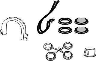
Parts Supplied
A B C D
|
E |
F |
A. U-shaped hose form |
D. Inlet hose washer/screen (2) |
|
B. Water inlet hoses (2) |
E. Clear plastic plug |
|
C. Inlet hose washer (2) |
F. Black plastic plug (2) |
|
Alternate Parts
If You Have: |
You Will Need to Buy: |
|
|
|
|
Laundry tub or |
Sump pump system (if not |
|
standpipe taller |
already available) |
|
than 35″ (89 cm) |
|
|
|
|
|
1″ (2.5 cm) diameter |
2″ (5 cm) diameter to 1″ |
|
standpipe |
(2.5 cm) diameter standpipe |
|
|
adapter, Part #3363920 |
|
|
|
|
Overhead sewer |
Standard 20 gal. (76 L) 35″ |
|
|
(89 cm) tall drain tub or utility |
|
|
sink, sump pump and |
|
|
connectors (available from |
|
|
local plumbing suppliers) |
|
|
|
|
Floor drain |
Siphon break, Part #285320; |
|
|
additional drain hose, Part |
|
|
#3357090 and connector kit, |
|
|
Part #285442 |
|
|
|
|
Drain hose too |
Drain hose, Part #388423 |
|
short |
and hose kit, Part #285442 |
|
|
|
|
Drain hose too long |
Hose kit, Part #285442 |
|
|
|
|
Lint clogged drain |
Drain protector, Part #367031 |
|
|
|
|
Water faucets |
2 longer water fill hoses: |
|
beyond reach of fill |
6 ft (1.8 m) Part #76314 |
|
hoses |
||
10 ft (3.0 m) Part #350008 |
||
|
||
|
|
|
Installing new |
British to universal hose |
|
water inlet hoses |
adapter, Part #3357451 |
|
|
|
2-1
LOCATION REQUIREMENTS
Selecting the proper location for your washer improves performance and minimizes noise and possible washer “walk.”
The washer can be installed in a basement, laundry room, closet, or recessed area (see “Drain System”).
IMPORTANT: Do not install or store the washer where it will be exposed to the weather.
Proper installation is your responsibility.
You Will Need
•A water heater set to deliver 120°F (49°C) water to the washer.
•A grounded electrical outlet located within 5 ft (1.5 m) of where the power cord is attached to the back of the washer (see “Electrical Requirements”).
•Hot and cold water faucets located within 3-1/2 ft (1.1 m) of the hot and cold water fill valves, and water pressure of 5-100 psi (34.5-690 kPa).
•A level floor with a maximum slope of 3/4″ (1.9 cm) under entire washer. Installing the washer on carpeting is not recommended.
•A sturdy floor to support the washer weight (washer, water and load) of 260 lbs (118 kg).
•Do not store or operate your washer in temperatures at or below 38°F (3.33°C). Some water can remain in the washer and can cause damage in low temperatures.
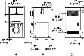
Recessed Area Or Closet Installation
The dimensions shown are for the recommended spacing allowed, except the closet door ventilation openings. The dimensions shown for the closet door ventilation openings are the minimum required.
23-3/8" 


(59.37 cm)
23-1/8" |
(58.74 cm)
Front View |
Side View |
Closet Door With Vents |
•Additional spacing should be considered for ease of installation and servicing.
•Additional clearances may be required for wall, door and floor moldings.
•Additional spacing of 1″ (2.5 cm) on all sides of the washer is recommended to reduce noise transfer.
•If a closet door is installed, the minimum air openings in the top and bottom of the door are required. Louvered doors with air openings in the top and bottom are acceptable.
•Companion appliance spacing should also be considered.
2-2
ELECTRICAL REQUIREMENTS
 WARNING
Electrical Shock Hazard
Plug into a grounded 3 prong outlet.
Do not remove ground prong.
Do not use an adapter.
Do not use an extension cord.
Failure to follow these instructions can result in death, fire, or electrical shock.
•A 120-volt, 60-Hz., AC-only, 15or 20-amp, fused electrical supply is required. A timedelay fuse or circuit breaker is recommended. It is recommended that a separate circuit serving only this appliance be provided.
•This washer is equipped with a power supply cord having a 3 prong grounding plug.
•To minimize possible shock hazard, the cord must be plugged into a mating, 3 prong, grounding-type outlet, grounded in accordance with local codes and ordinances. If a mating outlet is not available, it is the personal responsibility and obligation of the customer to have the properly grounded outlet installed by a qualified electrician.
•If codes permit and a separate ground wire is used, it is recommended that a qualified electrician determine that the ground path is adequate.
•Do not ground to a gas pipe.
•Check with a qualified electrician if you are not sure the washer is properly grounded.
•Do not have a fuse in the neutral or ground circuit.
GROUNDING INSTRUCTIONS
For a grounded, cord-connected washer:
This washer must be grounded. In the event of a malfunction or breakdown, grounding will reduce the risk of electrical shock by providing a path of least resistance for electric current. This washer is equipped with a cord having an equip- ment-grounding conductor and a grounding plug. The plug must be plugged into an appropriate outlet that is properly installed and grounded in accordance with all local codes and ordinances.
WARNING: Improper connection of the equipment-grounding conductor can result in a risk of electric shock. Check with a qualified electrician or serviceman if you are in doubt as to whether the appliance is properly grounded.
Do not modify the plug provided with the appliance – if it will not fit the outlet, have a proper outlet installed by a qualified electrician.
For a permanently connected washer:
This washer must be connected to a grounded metal, permanent wiring system, or an equipment grounding conductor must be run with the circuit conductors and connected to the equipment-ground- ing terminal or lead on the appliance.
2-3

INSTALLATION INSTRUCTIONS
 WARNING
Excessive Weight Hazard
Use two or more people to move and install washer.
Failure to do so can result in back or other injury.
•To prevent floor damage, set the washer onto cardboard before moving across floor.
•Move the washer to within approximately 3 ft (90 cm) of the final location.
REMOVE TRANSPORT SYSTEM
To install the machine, follow the steps below:
1.Move the machine to its installation position and remove the outer wrapping and the polystyrene base.
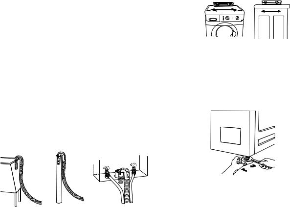
2.For transport reasons, the drum is locked in position. Loosen the four locking bolts and remove them along with the plastic spacers.
A
B
C
D
 E
E
3.Next, loosen the two locking screws “A” and remove the two bars “B,” as illustrated below. Keep the bolts, screws, spacers and bars for future use.
 A
A

 B
B
A.Screw (2)
B.Transit Bar (2)
4.Plug the holes with the 4 clear plastic plugs and 2 black plastic plugs, packed inside the parts bag.
A. Splined spacer (4) |
D. Transit bolt (4) |
B. Spacer (4) |
E. Screw (2) |
C. Washer (4) |
|
NOTE: If the plastic spacers cannot be removed from the machine, open the side panel by loosening the screws indicated as “E” above. Remove the spacers and replace the panel.
NOTE: If the washer is to be transported at a later date, call your local service center.
2-4
DRAIN SYSTEM
The washer can be installed using the standpipe drain system (floor or wall), the laundry tub drain system, or the floor drain system. Select the drain hose installation method you need (see “Tools and Parts”).
Standpipe Drain System
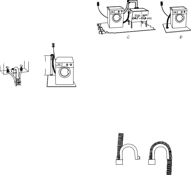
Wall Or Floor (Views A & B)
The standpipe drain requires a minimum diameter standpipe of 2″ (5 cm). The minimum carry-away capacity can be no less than 4.2 gal. (15.9 L) per minute. A 2″ (5 cm) diameter to 1″ (2.5 cm) diameter standpipe adapter kit is available (see “Tools and Parts”).
The top of the standpipe must be at least 23.5″ (59.7 cm) high and no higher than 72″ (182.88 cm)
from the bottom of the washer.
Floor Drain System (View D)
The floor drain system requires a siphon break that may be purchased separately (see “Tools and Parts”).
The siphon break must be a minimum of 28″ (71 cm) from the bottom of the washer. Additional hoses might be needed.
The minimum carry-away capacity can be no less than 4.2 gal. (15.9 L) per minute.
23.5 - 35"
(59.7 - 88.9 cm) 
A B
Laundry Tub Drain System (View C)
The laundry tub requires a minimum carryaway capacity of 4.2 gal. (15.9 L) per minute.
The top of the laundry tub must be at least 23.5″
(59.7 cm) above the floor and no higher than 72″ (182.88 cm) from the bottom of the washer.
CONNECT DRAIN HOSE
Proper connection of the drain hose will protect your floors from damage due to water leakage. To prevent the drain hose from coming off or leaking, it must be installed per the following instructions.
IMPORTANT: To ensure proper installation, this procedure must be followed exactly.
For standpipe or laundry tub drain systems:
1.Check the drain hose to see that it is the proper length.
2.Install the U-shaped hose form to end of the drain hose to create a hook-shaped end; as shown.
A B
A.Snap either end of the U-shaped hose form to the drain hose at the point where the corrugation begins.
B.Bend drain hose over the form and snap into place.
2-5

3.Place hooked end of drain hose into laundry tub or standpipe.
To prevent drain water from going back into the washer:
•Do not straighten hooked end of drain hose. Do not force excess drain hose into standpipe. Hose should be secure, but loose enough to provide a gap of air.
NOTE: To prevent siphoning, do not seal the drain hose to the standpipe.
•Do not lay excess drain hose in bottom of laundry tub.
•For floor drain installation, see kit number required under “Tools and Parts.”
CONNECT THE INLET HOSES
There are two hoses provided with the machine. The hot water hose is indicated with a red stripe running the length of the hose.
Insert new flat washers (supplied) into the straight hose fitting of each inlet hose. Firmly seat the washers in the couplings.
AB
A.Coupling
B.Washer
Connect The Inlet Hoses To The Water Faucets
Make sure the washer basket is empty.
1.Attach the hose with the red stripe to the hot water faucet. Screw on coupling by hand until seated on the washer.
2.Attach the other hose to the cold water faucet. Screw on coupling by hand until seated on the washer.
3.Using pliers, tighten the couplings with an additional two-thirds turn.
NOTE: Do not overtighten. Damage to the valves can result.
Clear The Water Lines
Run water through both faucets and inlet hoses, into a bucket or laundry tub, to get rid of particles in the water lines that might clog the inlet filter washers. The water should be clean, especially where the system is new or has been left unused for a length of time.
Connect The Inlet Hoses To The Washer
1.Insert the filter washer (supplied) into the coupling of the hose fitting elbow, before connecting the water inlet hose to the valve on the back of the washer.
2.Attach the hose with the red stripe to the HOT (right) inlet valve on the washer. Screw on coupling by hand until it is seated on the washer. Make sure the hose connection is tight.
NOTE: Do not overtighten. Damage to the valves can result.
3.Attach the other hose to the COLD water (left) inlet valve. Screw on coupling by hand until it is seated on the washer. Make sure the hose connection is tight.
NOTE: Do not overtighten. Damage to the valves can result.
B
A
A.Cold water inlet valve
B.Hot water inlet valve
2-6
Check For Leaks
Turn on the water faucets and check for leaks. A small amount of water might enter the washer. You will drain this later.
NOTE: Replace inlet hoses after 5 years of use to reduce the risk of hose failure. Record hose installation or replacement dates for future reference. Periodically inspect and replace hoses if bulges, kinks, cuts, wear, or leaks are found.
SECURE DRAIN HOSE
1.Drape the power cord over the console.
2.Move the washer to its final location and remove any cardboard used to move washer.
3.Place the drain hose in the laundry tub or standpipe as shown (see illustrations A and B).
4.If the washer faucets and the drain standpipe are recessed, place the hooked end of the drain hose in the standpipe as shown (see illustration C).
LEVEL THE WASHER
Properly leveling your washer prevents excessive noise and vibration.
1.Move washer to final location.
2.Check that the washer is level. Check side to side and back to front by lining up the level, as shown in the following illustration.
3.If the washer is not level, prop up the front of the washer with the wood block and adjust the feet up or down as necessary. If the washer is against a wall, move the washer out slightly before tipping back. Repeat this step until washer is level.
A B C
NOTE:
•Do not force excess drain hose back into the rear of the washer.
•To prevent siphoning, do not seal the drain hose into the standpipe.
COMPLETE THE INSTALLATION
1.Check the electrical requirements. Be sure that you have the correct electrical supply and the recommended grounding method (see “Electrical Requirements”).
2.Check to be sure all parts are now installed. If there is an extra part, go back through the steps to see which step was skipped.
3.Dispose of or recycle all packaging materials. Keep the shipping bolts, spacers, and transport bars for use if the washer should be transported.
4.Check to be sure the water faucets are on.
5.Check for leaks around faucets and inlet hoses.
2-7

 WARNING
Electrical Shock Hazard
Plug into a grounded 3 prong outlet.
Do not remove ground prong.
Do not use an adapter.
Do not use an extension cord.
Failure to follow these instructions can result in death, fire, or electrical shock.
6.Plug into a grounded 3 prong outlet.
7.Read “Washer Use.”
8.To test your washer, measure and add 1/2 the normal recommended amount of High Efficiency (HE) detergent to the washer. Close the door. Select any cycle, and then press START. Allow it to complete one whole cycle.
2-8

PRODUCT OPERATION
THEORY OF OPERATION
PRESSURE SWITCH
Various water levels will be used during different cycles. A single level pressure switch is utilized to determine the low water level setting. When the cycle requires the high or maximum water setting, the electronic control will calculate additional water levels, according to the type and quantity of load placed in the tub, and the cycle selected. These fill levels are based on time (see the following example).
LEVEL |
|
|
(Liters) |
|
|
HIGHEST (15) |
|
|
HIGH (13) |
|
|
BASE (7.5) |
|
|
40 |
70 |
TIME (seconds) |
80 |
Switch contacts P11 to P14 are used to determine the base water level. Should an overfill condition occur, contacts P11 to P16 will be made, shutting off the water supply, and signaling the electronic control to turn on the drain pump.
P11 to P14 are also used to indicate to the electronic control that water is in the tub, allowing the heating element to be energized.
P14
P12
P11 P16
P16
Pressure Switch Contacts
HEATING ELEMENT AND
TEMPERATURE SENSOR
This washer utilizes a fused heating element to heat the water during certain cycles. A temperature sensor measures the water temperature, and sends a resistance value to the electronic control.
In case of a failure in the heating element circuit, the electronic control will default to a maximum heating time of 30 minutes for each heating phase. After that default time, the washer will complete the program with the colder water.
THE WATER INLET VALVES
There are two water inlet valves on the washer. Depending on the cycle and water temperature, the electronic control will energize either the hot or cold water valve solenoid, to produce the selected water temperature.
THE DOOR LOCK SWITCH
The door lock switch consists of a heater and bimetal. When a cycle starts, the heater is energized, which causes the bimetal to warp, and lock the door. Upon completion of the cycle, the heater de-energizes. After the bimetal cools, (up to two minutes), the door can be unlocked.
BP1 
HEATER
BP3 |
BP2 |
3-1

DETERGENT DISPENSER
ASSEMBLY
The detergent dispenser is activated by two wax motors. During the Wash cycle, wax motor A is energized. This moves the diverter, inside the dispenser assembly, to flush the detergent cavity.
During the Rinse cycle, wax motor B is energized, to perform the same function for the fabric softener.
Wax Motors
B A
NOTE: There is no provision for, nor is it recommended, that the customer use bleach in this washer.
3-2
WASHER USE
 WARNING
Fire Hazard
Never place items in the washer that are dampened with gasoline or other flammable fluids.
No washer can completely remove oil.
Do not dry anything that has ever had any type of oil on it (including cooking oils).
Doing so can result in death, explosion, or fire.
STARTING THE WASHER
WARNING: To reduce the risk of fire, electric shock, or injury to persons, read the IMPORTANT SAFETY INSTRUCTIONS in the “Use And Care Guide” before operating this appliance.
The following is a guide to using your washer. Please refer to specific sections of the “Use And Care Guide” for more detailed information.
Do not store laundry products on the top surface of this washer. Vibration is normal during operation.
First Wash Cycle Without Laundry
Before washing clothes for the first time, select the REGULAR/NORMAL cycle and run the washer without clothes. Use 1/2 the normal recommended amount of powdered or liquid High Efficiency (HE) detergent. This initial cycle serves to ensure the interior is clean before washing clothes.
1.To load washer:
Open the washer door by pulling on the handle. Sort laundry according to color and type of fabric. Place a load of sorted clothes in the washer. Do not overload washer. Overloading can cause poor cleaning.
•The washer can be fully loaded, but not tightly packed. Washer door should close easily.
•Mix large and small items and avoid washing single items. Load evenly.
•Wash small items, such as infant socks, in mesh garment bags. It is recommended that more than one garment bag be used, and that each garment bag be filled with equal amounts of material.
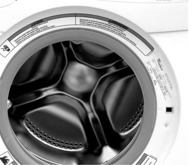
•When unloading garments, occasionally check under the rubber rim at the front of the tub for small items.
2.Close the washer door by pushing it firmly until the lock clicks. The washer door will remain locked during the wash cycle.
3-3
3.Open the dispenser drawer and add laundry products to the detergent or fabric softener compartments. Close drawer slowly to avoid spills (see “Using the Dispenser”).
IMPORTANT: To avoid damage to clothing, do not use liquid bleach or powdered color-safe bleach in this washer. If you need extra whitening, use a HE powder detergent with bleach additive.
NOTE:
•For best performance, use High Efficiency detergents. The package for this type of detergent will be marked “HE” or “High Efficiency.” The wash action along with less water could create too much sudsing with a regular detergent.
•Use only HE detergent made for frontloading washers and follow label instructions. The amount of detergent varies among the different brands, but for most detergents, you need only one or two tablespoons. Too much detergent could leave a residue on your clothes and possibly damage the appliance.
•Do not add detergent to the Pre Wash compartment unless you have selected the Pre Wash option. If you have detergent in both the Pre Wash and Main Wash compartments, and have not selected a Pre Wash option, the washer could oversuds and spill onto the floor.
•If you select the Pre Wash option, use powdered HE detergent in the Main Wash compartment. If you use liquid detergent in the Main Wash compartment, it will dispense immediately.
•Excessive use of fabric softener can damage garments.
•Close the detergent drawer securely.
IMPORTANT: To avoid water spillage, do not open the detergent drawer while the machine is operating.
4.Turn on the washer by selecting POWER.
5.Select one of the cycles by turning the cycle selector. The preset settings provide the recommended fabric care for the selected cycle.
6.Select the desired options. Not all options are available with all cycles.
7.To begin the wash cycle Select START. Whenthewashcycleiscomplete,theDONE status light glows, the door unlocks, and the wash load can be removed from the washer. To power down the washer manually after the wash cycle is complete, press POWER once.
USING THE DISPENSER
The washer has a dispenser drawer with three separate compartments for your laundry products. Two are for detergent, and one is for liquid fabric softener. Laundry products are diluted and dispensed automatically at the proper time during the wash cycle, making it unnecessary for you to return to the washer during the cycle to add them.
It is normal for small amounts of water to remain in the dispensers when the wash cycle is complete.
Do not add laundry additives directly into the wash tub. Always use the proper dispensers when adding laundry products.
Choosing The Right Detergent
For best washing performance, use a High Efficiency (HE), or low-sudsing, detergent.
3-4
 Loading...