


Duet Sport YWED8300SB2
ELECTRONIC
ELECTRICDRYER
[_;_ & _[,_i__ v&_
For assistance, installation and service call: 1-800-807-6777
or visit our website at... www.whirlpool.ca
P
SECHEUSE
ELECTRIQUE
ELECTRONIQUE
W10151581A
Pour assistance, installation ou service composez le :
ou visitez notre site web & www,whirlpool.ca
Table of Contents/Table des matieres ......................... 2
1-800-807-6777
TABLEOFCONTENTS
TABLEDESMATIERES
DRYER SAFETY .............................................................................. 3
INSTALLATION INSTRUCTIONS .................................................. 4
Tools and Parts ............................................................................ 4
Optional Pedestal ......................................................................... 4
Location Requirements ................................................................ 5
Electrical Requirements ............................................................... 7
Venting Requirements .................................................................. 7
Plan Vent System ......................................................................... 8
Install Vent System ..................................................................... 10
Install Leveling Legs ................................................................... 10
Connect Vent .............................................................................. 10
Level Dryer ................................................................................. 10
Reverse Door Swing .................................................................. 10
Complete Installation ................................................................. 12
DRYER USE .................................................................................. 13
Starting Your Dryer ..................................................................... 13
Stopping or Restarting Your Dryer ............................................ 14
Lock Controls ............................................................................. 14
Drying and Cycle Tips ................................................................ 14
Status Lights .............................................................................. 14
Cycles ......................................................................................... 15
Additional Features .................................................................... 16
Changing Cycles, Options and Modifiers .................................. 16
Drying Rack Option .................................................................... 16
DRYER CARE .............................................................................. 17
Cleaning the Dryer Location ...................................................... 17
Cleaning the Lint Screen ............................................................ 17
Cleaning the Dryer Interior ......................................................... 18
Removing Accumulated Lint ...................................................... 18
Vacation and Moving Care ......................................................... 18
TROUBLESHOOTING .................................................................. 18
ASSISTANCE OR SERVICE ......................................................... 20
ACCESSORIES ............................................................................. 20
WARRANTY .................................................................................. 21
SI!:CURITg: DE LA SI!:CHEUSE .................................................... 22
INSTRUCTIONS D'INSTALLATION ............................................. 23
Outillage et pieces ...................................................................... 23
Piedestal facultatif ...................................................................... 23
Exigences d'emplacement ......................................................... 24
Specifications electriques .......................................................... 26
Exigences concernant I'evacuation ........................................... 26
Planification du systeme d'evacuation ...................................... 28
Installation du systeme d'evacuation ......................................... 29
Installation des pieds de nivellement ......................................... 29
Raccordement du conduit d'evacuation ................................... 30
Mise a niveau de la secheuse .................................................... 30
Inversion du sens d'ouverture de la porte ................................. 30
Achever I'installation .................................................................. 32
UTILISATION DE LA S¢:CHEUSE ................................................ 33
Mise en marche de la secheuse ................................................ 33
Arr_t ou remise en marche de la secheuse ............................... 34
Verrouillage des commandes ..................................................... 34
Conseils pour lesechage et les programmes ........................... 34
Temoins lumineux ...................................................................... 35
Programmes ............................................................................... 35
Caracteristiques supplementaires ............................................. 36
Changement des programmes, options et modificateurs .........37
Option de grille de sechage ....................................................... 37
ENTRETIEN DE LA S¢:CHEUSE ................................................. 38
Nettoyage de I'emplacement de la secheuse ........................... 38
Nettoyage du filtre a charpie ...................................................... 38
Nettoyage de I'interieur de la secheuse ..................................... 39
Retrait de la charpie accumulee ................................................ 39
Precautions a prendre pour les vacances et
avant un demenagement ........................................................... 39
DC:PANNAGE ................................................................................. 40
ASSISTANCE OU SERVICE ......................................................... 42
ACCESSOIRES ............................................................................. 42
GARANTIE ..................................................................................... 43
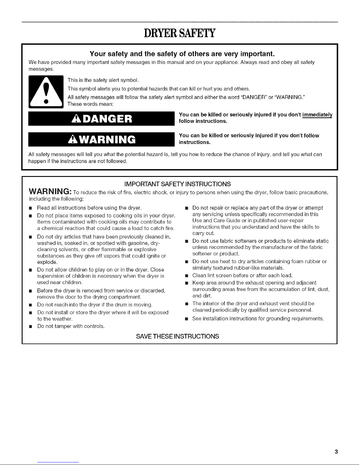
DRYERSAFETY
Your safety and the safety of others are very important.
We have provided many important safety messages in this manual and on your appliance. Always read and obey all safety
messages.
This is the safety alert symbol.
This symbol alerts you to potential hazards that can kill or hurt you and others.
All safety messages will follow the safety alert symbol and either the word "DANGER" or "WARNING."
These words mean:
You can be killed or seriously injured if you don't immediately
follow instructions.
You can be killed or seriously injured if you don't follow
instructions.
All safety messages will tell you what the potential hazard is, tell you how to reduce the chance of injury, and tell you what can
happen if the instructions are not followed.
IMPORTANT SAFETY iNSTRUCTiONS
WARNING; To reduce the risk of fire, electric shock, or injury to persons when using the dryer, follow basic precautions,
including the following:
[] Read all instructions before using the dryer.
[] Do not place items exposed to cooking oils in your dryer.
Items contaminated with cooking oils may contribute to
a chemical reaction that could cause a load to catch fire.
[] Do not dry articles that have been previously cleaned in,
washed in, soaked in, or spotted with gasoline, dry-
cleaning solvents, or other flammable or explosive
substances as they give off vapors that could ignite or
explode.
[] Do not allow children to play on or in the dryer. Close
supervision of children is necessary when the dryer is
used near children.
[] Before the dryer is removed from service or discarded,
remove the door to the drying compartment.
[] Do not reach into the dryer if the drum is moving.
[] Do not install or store the dryer where it will be exposed
to the weather.
[] Do not tamper with controls.
SAVE THESE iNSTRUCTiONS
[] Do not repair or replace any part of the dryer or attempt
any servicing unless specifically recommended in this
Use and Care Guide or in published user-repair
instructions that you understand and have the skills to
carry out.
[] Do not use fabric softeners or products to eliminate static
unless recommended by the manufacturer of the fabric
softener or product.
[] Do not use heat to dry articles containing foam rubber or
similarly textured rubber-like materials.
[] Clean lint screen before or after each load.
[] Keep area around the exhaust opening and adjacent
surrounding areas free from the accumulation of lint, dust,
and dirt.
[] The interior of the dryer and exhaust vent should be
cleaned periodically by qualified service personnel.
[] See installation instructions for grounding requirements.
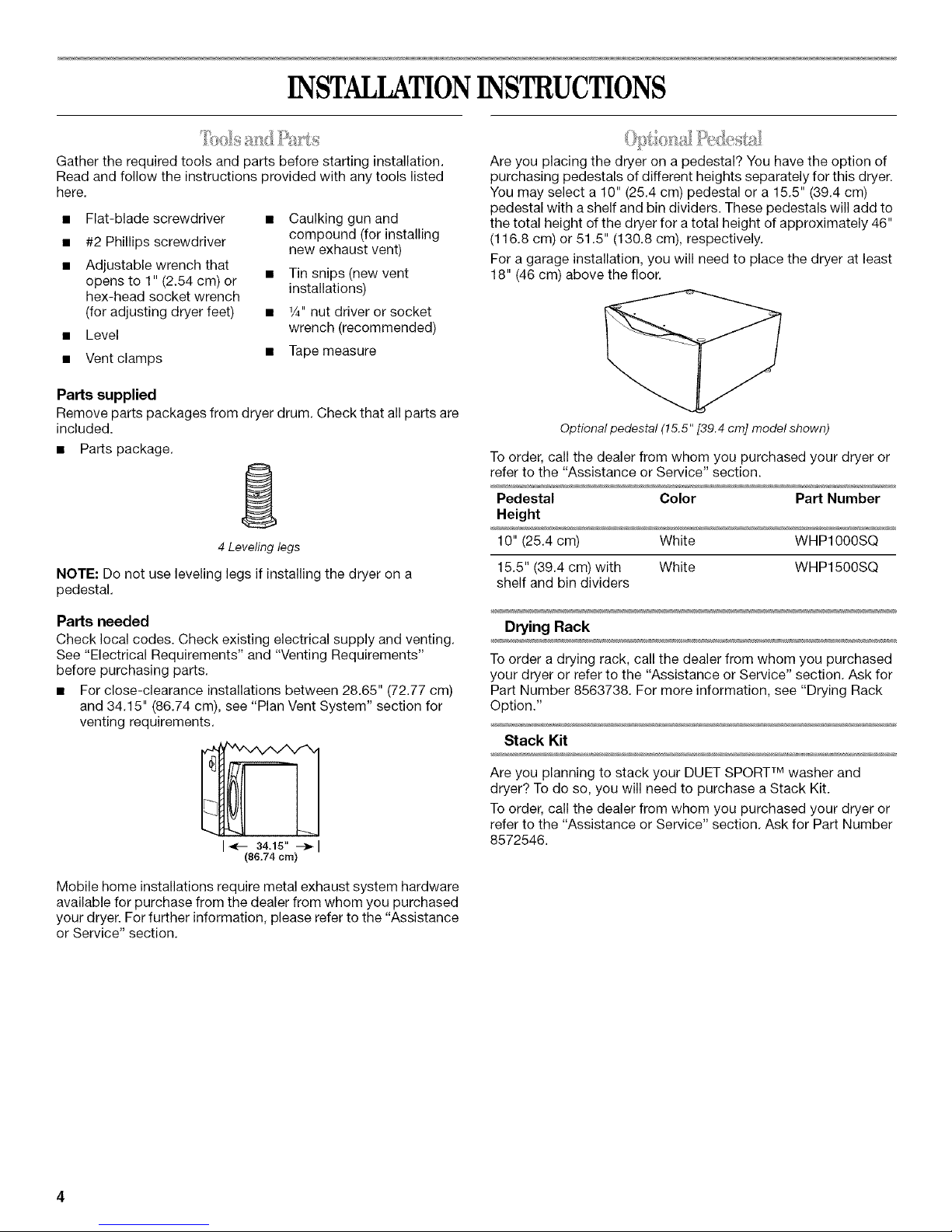
INSTALLATIONINSTRUCTIONS
Gather the required tools and parts before starting installation.
Read and follow the instructions provided with any tools listed
here.
• Flat-blade screwdriver • Caulking gun and
compound (for installing
• #2 Phillips screwdriver new exhaust vent)
• Adjustable wrench that
opens to 1" (2.54 cm) or • Tin snips (new vent
hex-head socket wrench installations)
(for adjusting dryer feet) • 1/4"nut driver or socket
• Level wrench (recommended)
• Vent clamps • Tape measure
Parts supplied
Remove parts packages from dryer drum. Check that all parts are
included.
• Pa_s package.
4 Leveling legs
NOTE: Do not use leveling legs if installing the dryer on a
pedestal.
Are you placing the dryer on a pedestal? You have the option of
purchasing pedestals of different heights separately for this dryer.
You may select a 10" (25.4 cm) pedestal or a 15.5" (39.4 cm)
pedestal with a shelf and bin dividers. These pedestals will add to
the total height of the dryer for a total height of approximately 46"
(116.8 cm) or 51.5" (130.8 cm), respectively.
For a garage installation, you will need to place the dryer at least
18" (46 cm) above the floor.
Optional pedestal (15.5" [39.4 cm] model shown)
To order, call the dealer from whom you purchased your dryer or
refer to the "Assistance or Service" section.
Pedestal Color Part Number
Height
10" (25.4 cm) White WHP1000SQ
15.5" (39.4 cm) with White WHP1500SQ
shelf and bin dividers
Parts needed
Check local codes. Check existing electrical supply and venting.
See "Electrical Requirements" and "Venting Requirements"
before purchasing parts.
• For close-clearance installations between 28.65" (72.77 cm)
and 34.15" (86.74 cm), see "Plan Vent System" section for
venting requirements.
I_- 34.15" --_1
(86.74 cm)
Mobile home installations require metal exhaust system hardware
available for purchase from the dealer from whom you purchased
your dryer. For further information, please refer to the "Assistance
or Service" section.
Drying Rack
To order a drying rack, call the dealer from whom you purchased
your dryer or refer to the "Assistance or Service" section. Ask for
Part Number 8563738. For more information, see "Drying Rack
Option."
Stack Kit
Are you planning to stack your DUET SPORT TM washer and
dryer? To do so, you will need to purchase a Stack Kit.
To order, call the dealer from whom you purchased your dryer or
refer to the "Assistance or Service" section. Ask for Part Number
8572546.
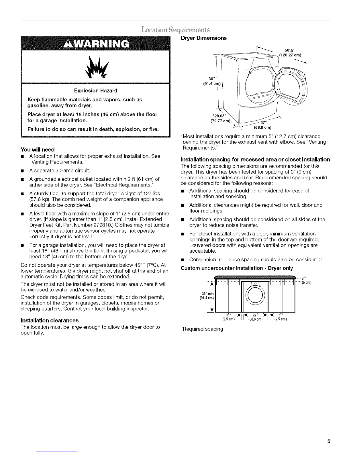
Dryer Dimensions
501/2"
(128.27 cm)
Explosion Hazard
Keep flammable materials and vapors, such as
gasoline, away from dryer.
Place dryer at least 18 inches (46 cm) above the floor
for a garage installation.
Failure to do so can result in death, explosion, or fire.
You will need
• A location that allows for proper exhaust installation. See
"Venting Requirements."
• A separate 30-amp circuit.
• A grounded electrical outlet located within 2 ft (61 cm) of
either side of the dryer. See "Electrical Requirements."
• A sturdy floor to support the total dryer weight of 127 Ibs
(57.6 kg). The combined weight of a companion appliance
should also be considered.
A level floor with a maximum slope of 1" (2.5 cm) under entire
dryer. (If slope is greater than 1" [2.5 cm], install Extended
Dryer Feet Kit, Part Number 279810.) Clothes may not tumble
properly and automatic sensor cycles may not operate
correctly if dryer is not level.
• For a garage installation, you will need to place the dryer at
least 18" (46 cm) above the floor. If using a pedestal, you will
need 18" (46 cm) to the bottom of the dryer.
Do not operate your dryer at temperatures below 45°F (7°C). At
lower temperatures, the dryer might not shut off at the end of an
automatic cycle. Drying times can be extended.
The dryer must not be installed or stored in an area where it will
be exposed to water and/or weather.
Check code requirements. Some codes limit, or do not permit,
installation of the dryer in garages, closets, mobile homes or
sleeping quarters. Contact your local building inspector.
Installation clearances
The location must be large enough to allow the dryer door to
open fully.
!
36"
(91.4 cm)
*28.65"
(7237 cm), 27"
(68,6 cm)
i
*Most installations require a minimum 5" (12.7 cm) clearance
behind the dryer for the exhaust vent with elbow. See "Venting
Requirements."
Installation spacing for recessed area or closet installation
The following spacing dimensions are recommended for this
dryer. This dryer has been tested for spacing of 0" (0 cm)
clearance on the sides and rear. Recommended spacing should
be considered for the following reasons:
• Additional spacing should be considered for ease of
installation and servicing.
• Additional clearances might be required for wall, door and
floor moldings.
• Additional spacing should be considered on all sides of the
dryer to reduce noise transfer.
For closet installation, with a door, minimum ventilation
openings in the top and bottom of the door are required.
Louvered doors with equivalent ventilation openings are
acceptable.
• Companion appliance spacing should also be considered.
Custom undercounter installation - Dryer only
•-- 2"*
36"rain I
/"* _ "_'-'-2T'_ _ /"*
(2.5 crn) (686 crn) (2.5 crn)
*Required spacing
Closet installation - Dryer only
It ,8,°.2,
(155crn2) '
11"*_28.85"---_1s"**l
{2.5crn) (72.77 crn){12.7crn)
A B
A.Side view - closet or confined area
B.Closet door with vents
* Required spacing
**For side or bottom venting, 0" (0 cm) spacing is allowed.
Recessed or closet installation - Dryer on pedestal
-LIJ1,m,,,I.
3"*
(7.6 crn)
Recommended installation spacing for recessed or
closet installation, with stacked washer and dryer
Thedimensions shown arefor the recommended spacing.
48 in.2 *
(310 cm 2)
3"* (7.6 cm)
m
4,
T
o
3"* (7.6 cm)
24 in.2*
(155crn2)
*Required spacing
6"*(;.2 ¢rn)
,=&_-1"* (2.5 crn)
t
72"
(182.9 crn)
1"-)41<-- 27,,--_11_- 1,,
(2.5cm)
* Required spacing
**For side or bottom venting, 0" (0 cm) spacing is allowed.
(68.6 crn) (2.5 cm) (2.5 crn) (72.77 cm) (12.7 cm)
A B
A.Recessed area
B.Side view - closet or confined area
1"*I I*- 28.65"--_ls"**l
Recommended installation spacing for cabinet
installation
For cabinet installation, with a door, minimum ventilation
openings in the top of the cabinet are required.
" • 7"*(17.8cm)
!!
crn) 5"** 28,65" 1"*
I/%0m/
5"* --_,
(12.7cm)
*Required spacing
Mobile home - additional installation requirements
This dryer is suitable for mobile home installations.
The installation must conform to the Canadian Manufactured
Home Standard, CAN/CSA Z240 MH.
Mobile home installations require:
• Metal exhaust system hardware, which is available for
purchase from your dealer.
Special provisions must be made in mobile homes to
introduce outside air into the dryer. The opening (such as a
nearby window) should be at least twice as large as the dryer
exhaust opening.
(2.5 cm)
27,, 1 /2?;'oml
68.6 cm
(12.7 crn) (72.77 crn) (2.5 crn) (2.5 cm)(68.6 crn) (2.5 crn)
* Required spacing
**For side or bottom venting, 0" (0 cm) spacing is allowed.
1" 27" 1"
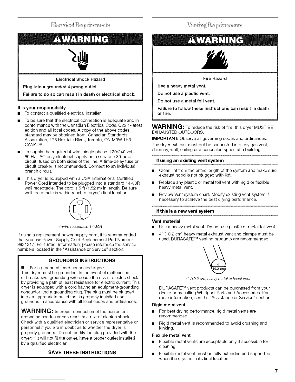
ElectricalShock Hazard
Plug into a grounded 4 prong outlet.
Failure to do so can result in death or electrical shock.
It is your responsibility
• Tocontact a qualified electrical installer.
To be sure that the electrical connection is adequate and in
conformance with the Canadian Electrical Code, C22.1 -latest
edition and all local codes. A copy of the above codes
standard may be obtained from: Canadian Standards
Association, 178 Rexdale Blvd., Toronto, ON MRW 1R3
CANADA.
To supply the required 4 wire, single phase, 120/240 volt,
60 Hz., AC only electrical supply on a separate 30-amp
circuit, fused on both sides of the line. A time-delay fuse or
circuit breaker is recommended. Connect to an individual
branch circuit.
This dryer is equipped with a CSA International Certified
Power Cord intended to be plugged into a standard 14-30R
wall receptacle. The cord is 5 ft (1.52 m) in length. Be sure
wall receptacle is within reach of dryer's final location.
Fire Hazard
Use a heavy metal vent.
Do not use a plastic vent.
Do not use a metal foil vent.
Failure to follow these instructions can result in death
or fire.
WARNING: To reduce the risk of fire, this dryer MUST BE
EXHAUSTED OUTDOORS.
IMPORTANT: Observe all governing codes and ordinances.
The dryer exhaust must not be connected into any gas vent,
chimney, wall, ceiling or a concealed space of a building.
If using an existing vent system
• Clean lint from the entire length of the system and make sure
exhaust hood is not plugged with lint.
• Replace any plastic or metal foil vent with rigid or flexible
heavy metal vent.
• Review Vent system chart. Modify existing vent system if
necessary to achieve the best drying performance.
If this is a new vent system
4-wire receptacle 14-30R
If using a replacement power supply cord, it is recommended
that you use Power Supply Cord Replacement Part Number
9831317. For further information, please reference the service
numbers located in the "Assistance or Service" section.
GROUNDING INSTRUCTIONS
[] For a grounded, cord-connected dryer:
This dryer must be grounded. In the event of malfunction
or breakdown, grounding will reduce the risk of electric shock
by providing a path of least resistance for electric current. This
dryer is equipped with a cord having an equipment-grounding
conductor and a grounding plug. The plug must be plugged
into an appropriate outlet that is properly installed and
grounded in accordance with all local codes and ordinances.
WARNING: Improper connection of the equipment-
grounding conductor can result in a risk of electric shock.
Check with a qualified electrician or service representative or
personnel if you are in doubt as to whether the dryer is
properly grounded. Do not modify the plug provided with the
dryer: if it will not fit the outlet, have a proper outlet installed
by a qualified electrician.
SAVETHESEINSTRUCTIONS
Vent material
• Use a heavy metal vent. Do not use plastic or metal foil vent.
• 4" (10.2 cm) heavy metal exhaust vent and clamps must be
used. DURASAFF Mventing products are recommended.
4" (10.2cm) heavy metal exhaust vent
DURASAFF Mvent products can be purchased from your
dealer or by calling Whirlpool Parts and Accessories. For
more information, see the "Assistance or Service" section.
Rigid metal vent
• For best drying performance, rigid metal vents are
recommended.
• Rigid metal vent is recommended to avoid crushing and
kinking.
Flexible metal vent
• Flexible metal vents are acceptable only if accessible for
cleaning.
• Flexible metal vent must be fully extended and supported
when the dryer is in its final location.
• Removeexcessflexiblemetalventtoavoidsaggingand
kinkingthatmayresultinreducedairflowandpoor
performance.
• Donotinstallflexiblemetalventinenclosedwalls,ceilingsor
floors.
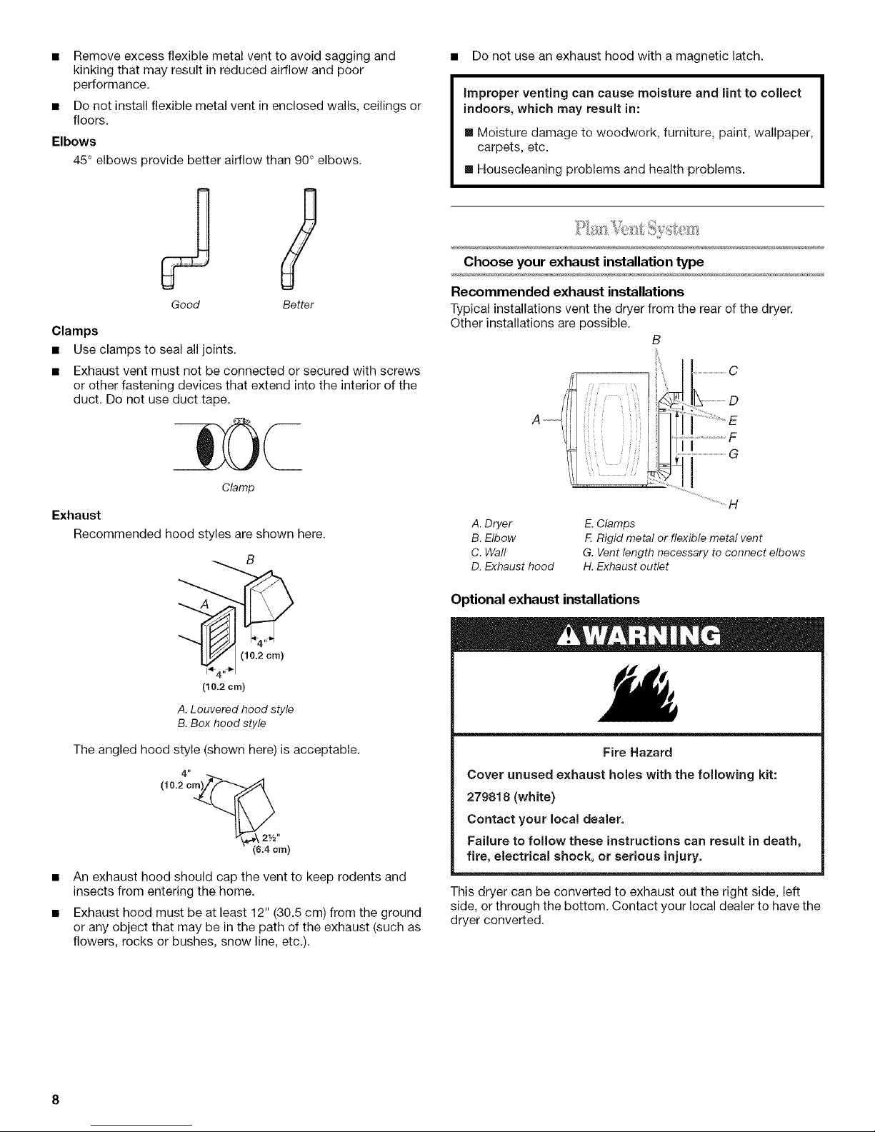
Elbows
45°elbowsprovidebetterairflowthan90°elbows.
• Do not use an exhaust hood with a magnetic latch.
improper venting can cause moisture and lint to collect
indoors, which may result in:
[] Moisture damage to woodwork, furniture, paint, wallpaper,
carpets, etc.
[] Housecleaning problems and health problems.
Choose your exhaust installation type
Good Better
Clamps
Use clamps to seal all joints.
Exhaust vent must not be connected or secured with screws
or other fastening devices that extend into the interior of the
duct. Do not use duct tape.
Clamp
Exhaust
Recommended hood styles are shown here.
B
(10.2 cm)
A. Louveredhood style
B.Box hood style
Recommended exhaust installations
Typical installations vent the dryer from the rear of the dryer.
Other installations are possible.
B
.....................................C
A .....
_.......................D
A. Dryer
B. Elbow
C. Wall
D. Exhaust hood
Optional exhaust installations
E. Clamps
E Rigid metal or flexible metal vent
G. Vent length necessary to connect elbows
H. Exhaust outlet
The angled hood style (shown here) is acceptable.
4"
(10.2 cm)_(_
An exhaust hood should cap the vent to keep rodents and
insects from entering the home.
Exhaust hood must be at least 12" (30.5 cm) from the ground
or any object that may be in the path of the exhaust (such as
flowers, rocks or bushes, snow line, etc.).
Fire Hazard
Cover unused exhaust holes with the following kit:
279818 (white)
Contact your local dealer.
Failure to follow these instructions can result in death,
fire, electrical shock, or serious injury.
This dryer can be converted to exhaust out the right side, left
side, or through the bottom. Contact your local dealer to have the
dryer converted.
A B C
A. Standard rear offset exhaust installation
B. Left or right side exhaust installation
C. Bottom exhaust installation (not an option
with pedestal installations)
Alternate installations for close clearances
Venting systems come in many varieties. Select the type best for
your installation. Two close-clearance installations are shown.
Refer to the manufacturer's instructions.
-i --- iI
t \\ I
\d_ _ _\_d'....
A B
A. Over-the-top installation (also available with one
offset elbow)
B. Periscope installation
NOTE: The following kits for close clearance alternate
installations are available for purchase. Please see the
"Assistance or Service" section to order.
• Over-the-Top Installation:
Part Number 4396028
• Periscope Installation (For use with dryer vent to wall vent
mismatch):
Part Number 4396037 - 0" (0 cm) to 18" (45.72 cm)
mismatch
Part Number 4396011 - 18" (45.72 cm) to 29" (73.66 cm)
mismatch
Part Number 4396014 - 29" (73.66 cm) to 50" (127 cm)
mismatch
Special provisions for mobile home installations
The exhaust vent must be securely fastened to a noncombustible
portion of the mobile home structure and must not terminate
beneath the mobile home. Terminate the exhaust vent outside.
Determine vent path
• Select the route that will provide the straightest and most
direct path outdoors.
• Plan the installation to use the fewest number of elbows and
turns.
• When using elbows or making turns, allow as much room as
possible.
• Bend vent gradually to avoid kinking.
• Use the fewest 90° turns possible.
Determine vent length and elbows needed for best
drying performance
• Use the following Vent system chart to determine type of vent
material and hood combinations acceptable to use.
NOTE: Do not use vent runs longer than those specified in
the Vent system chart. Exhaust systems longer than those
specified will:
• Shorten the life of the dryer.
• Reduce performance, resulting in longer drying times and
increased energy usage.
The Vent system chart provides venting requirements that will
help to achieve the best drying performance.
Vent system chart
NOTE: Side and bottom exhaust installations have a 90° turn
inside the dryer. To determine maximum exhaust length, add one
90° turn to the chart.
Number of Type of Box or Angled
90° turns vent Iouvered hoods
or elbows hoods
0 Rigid metal 64 ft (20 m) 58 ft (17.7 m)
Flexible metal 36 ft (11 m) 28 ft (8.5 m)
1 Rigid metal 54 ft (16.5 m) 48 ft (14.6 m)
Flexible metal 31 ft (9.4 m) 23 ft (7 m)
2 Rigid metal 44 ft (13.4 m) 38 ft (11.6 m)
Flexible metal 27 ft (8.2 m) 19 ft (5.8 m)
3 Rigid metal 35 ft (10.7 m) 29 ft (8.8 m)
Flexible metal 25 ft (7.6 m) 17 ft (5.2 m)
4 Rigid metal 27 ft (8.2 m) 21 ft (6.4 m)
Flexible metal 23 ft (7 m) 15 ft (4.6 m)
1. Installexhausthood.Usecaulkingcompoundtosealexterior
wallopeningaroundexhausthood.
2. Connectventtoexhausthood.Ventmustfitinsideexhaust
hood.Secureventtoexhausthoodwith4"(10.2cm)clamp.
3. Runventtodryerlocation.Usethestraightestpathpossible.
See"Determineventpath"in"PlanVentSystem."Avoid90°
turns.Useclampstosealalljoints.Donotuseducttape,
screwsorotherfasteningdevicesthatextendintotheinterior
oftheventtosecurevent.
Excessive Weight Hazard
Use two or more people to move and install dryer.
Failure to do so can result in back or other injury.
1. To protect the floor, use a large flat piece of cardboard from
the dryer carton. Place cardboard under the entire back edge
of the dryer.
2. Firmly grasp the body of the dryer (not the console panel).
Gently lay the dryer on the cardboard. See illustration.
1. Usinga4"(10.2cm)clamp,connectventtoexhaustoutletin
dryer.Ifconnectingtoexistingvent,makesuretheventis
clean.Thedryerventmustfitoverthedryerexhaustoutlet
andinsidetheexhausthood.Checkthattheventissecured
toexhausthoodwitha4"(10.2cm)clamp.
2. Movedryerintoitsfinallocation.Donotcrushorkinkvent.
3. (On gas models) Check that there are no kinks in the flexible
gas line.
4. Once the exhaust vent connection is made, remove the
corner posts and cardboard.
Check the levelness of the dryer. Check levelness first side to
side, then front to back.
If the dryer is not level, prop up the dryer using a wood block.
Use a wrench to adjust the legs up or down and check again for
levelness.
3.
Examine the leveling legs. Find the diamond marking.
1
4.
Screw the legs into the leg holes by hand. Use a wrench to
finish turning the legs until the diamond marking is no longer
visible.
5.
Place a carton corner post from dryer packaging under each
of the 2 dryer back corners. Stand the dryer up. Slide the
dryer on the corner posts until it is close to its final location.
Leave enough room to connect the exhaust vent.
_,W_ D__O___
You can change your door swing from a right-side opening to a
left-side opening, if desired.
1. Place a towel or soft cloth on top of the dryer or work space
to protect the surface.
Remove the door assembly
1. Remove the 4 screws that hold the door hinge on the front
panel of the dryer.
B
A.Dryer frontpanel
B.Door assembly
2.
Lay the door assembly on a flat, protected surface with the
inside (inner door assembly) facing up.
10
3=
Remove the 6 Phillips head screws to release the outer door
assembly from the inner door assembly, as indicated below.
See illustration. It is important that you remove only the
6 indicated screws.
4. Lift the inner door assembly off the outer door assembly.
5. Disengage locking tabs by rotating inner ring clockwise. See
illustration.
2=
Remove hinge cover.
A...............................(__
A. Door hinge
B. Plug strips
C. Hinge cover
3=
Remove the 4 screws that attach to the inner door hinge and
move the hinge to the other side. Reinstall the 4 screws.
®
A.Innerring
B.Outer ring
6. Turn inner ring 180 ° and lock tabs into place.
Reverse hinge
1. Use a small flat-blade screwdriver to remove 2 plug strips
from the inner door. Slide the head of the screwdriver under
the plugs, being certain not to scratch the inner door surface.
Lift up.
A. Door hinge
4. Reinstall plug strips on opposite side of the inner door.
5. Check for fingerprints on the glass. Clean glass if necessary.
6. Place the inner door assembly inside the outer door
assembly. To fit correctly, the inner door assembly edge fits
completely inside the outer door assembly edge.
7. Reassemble the inner and outer door assemblies with the
6 screws.
11
Reverse the strike
1. Use a small flat-blade screwdriver to remove plug strip from
the dryer door opening. Slide the head of the screwdriver
under the plugs, being certain not to scratch the dryer
surface. Lift up.
2. Remove the strike.
3. Insert strike and plug strip on the opposite side.
A
A.Plug strip (cannot be seenfrom thisangle)
B. Door strike
Reinstall the door
1. Reattach door to dryer front panel with the 4 screws.
®
1. Check that all parts are now installed. If there is an extra part,
go back through the steps to see which step was skipped.
2. Check that you have all of your tools.
3. Dispose of/recycle all packaging materials.
4. Check the dryer's final location. Be sure the vent is not
crushed or kinked.
5. Check that the dryer is level. See "Level Dryer."
6. Plug into a grounded 4 prong outlet. Turn on power.
7. Remove the blue protective film on the console and any tape
remaining on the dryer.
8. Read "Dryer Use."
9. Wipe the dryer drum interior thoroughly with a damp cloth to
remove any dust.
10. Select a Timed Dry heated cycle, and start the dryer. Do not
select the Air Only modifier.
If the dryer will not start, check the following:
• Controls are set in a running or "On" position.
• Start button has been pushed firmly.
• Dryer is plugged into a grounded outlet.
• Electrical supply is connected.
• Household fuse is intact and tight, or circuit breaker has
not tripped.
• Dryer door is closed.
11. When the dryer has been running for 5 minutes, open the
dryer door and feel for heat. If you feel heat, cancel cycle and
close the door.
If you do not feel heat, turn off the dryer and check the
following:
• There may be 2 fuses or circuit breakers for the dryer.
Make sure both fuses are intact and tight, or that both
circuit breakers have not tripped. If there is still no heat,
contact a qualified technician.
NOTE: You may notice a burning odor when the dryer is first
heated. This odor is common when the heating element is first
used. The odor will go away.
A. Dryer front panel
B. Door assembly
2. Check for fingerprints on the glass. Clean the glass if
necessary.
3. Close door and check that it latches securely.
12
\
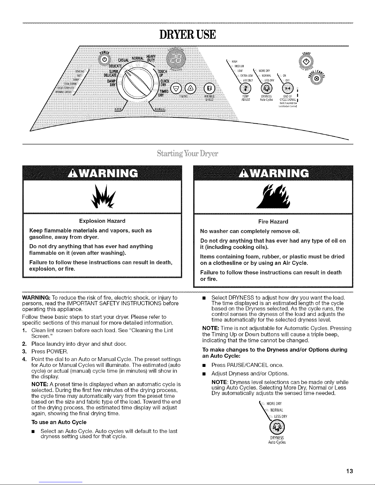
DRYERUSE
Explosion Hazard
Keep flammable materials and vapors, such as
gasoline, away from dryer.
Do not dry anything that has ever had anything
flammable on it (even after washing).
Failure to follow these instructions can result in death,
explosion, or fire.
WARNING: To reduce the risk of fire, electric shock, or injury to
persons, read the IMPORTANT SAFETY INSTRUCTIONS before
operating this appliance.
Follow these basic steps to start your dryer. Please refer to
specific sections of this manual for more detailed information.
1. Clean lint screen before each load. See "Cleaning the Lint
Screen."
2. Place laundry into dryer and shut door.
3. Press POWER.
4. Point the dial to an Auto or Manual Cycle. The preset settings
for Auto or Manual Cycles will illuminate. The estimated (auto
cycle) or actual (manual) cycle time (in minutes) will show in
the display.
NOTE: A preset time is displayed when an automatic cycle is
selected. During the first few minutes of the drying process,
the cycle time may automatically vary from the preset time
based on the size and fabric type of the load. Toward the end
of the drying process, the estimated time display will adjust
again, showing the final drying time.
To use an Auto Cycle
• Select an Auto Cycle. Auto cycles will default to the last
dryness setting used for that cycle.
Fire Hazard
No washer can completely remove oil.
Do not dry anything that has ever had any type of oil on
it (including cooking oils).
Items containing foam, rubber, or plastic must be dried
on a clothesline or by using an Air Cycle.
Failure to follow these instructions can result in death
or fire.
• Select DRYNESS to adjust how dry you want the load.
The time displayed is an estimated length of the cycle
based on the Dryness selected. As the cycle runs, the
control senses the dryness of the load and adjusts the
time automatically for the selected dryness level.
NOTE: Time is not adjustable for Automatic Cycles. Pressing
the Timing Up or Down buttons will cause a triple beep,
indicating that the time cannot be changed.
To make changes to the Dryness and/or Options during
an Auto Cycle:
• Press PAUSE/CANCEL once.
Adjust Dryness and/or Options.
NOTE: Dryness level selections can be made only while
using Auto Cycles. Selecting More Dry, Normal or Less
Dry automatically adjusts the sensed time needed.
MOREDRY
NORMAL
DRYNESS
AutoCycles
13
Auto Dry cycles take the guesswork out of drying time
and enhance fabric care.The amount of time that is
displayed is the estimated time remaining in the cycle.
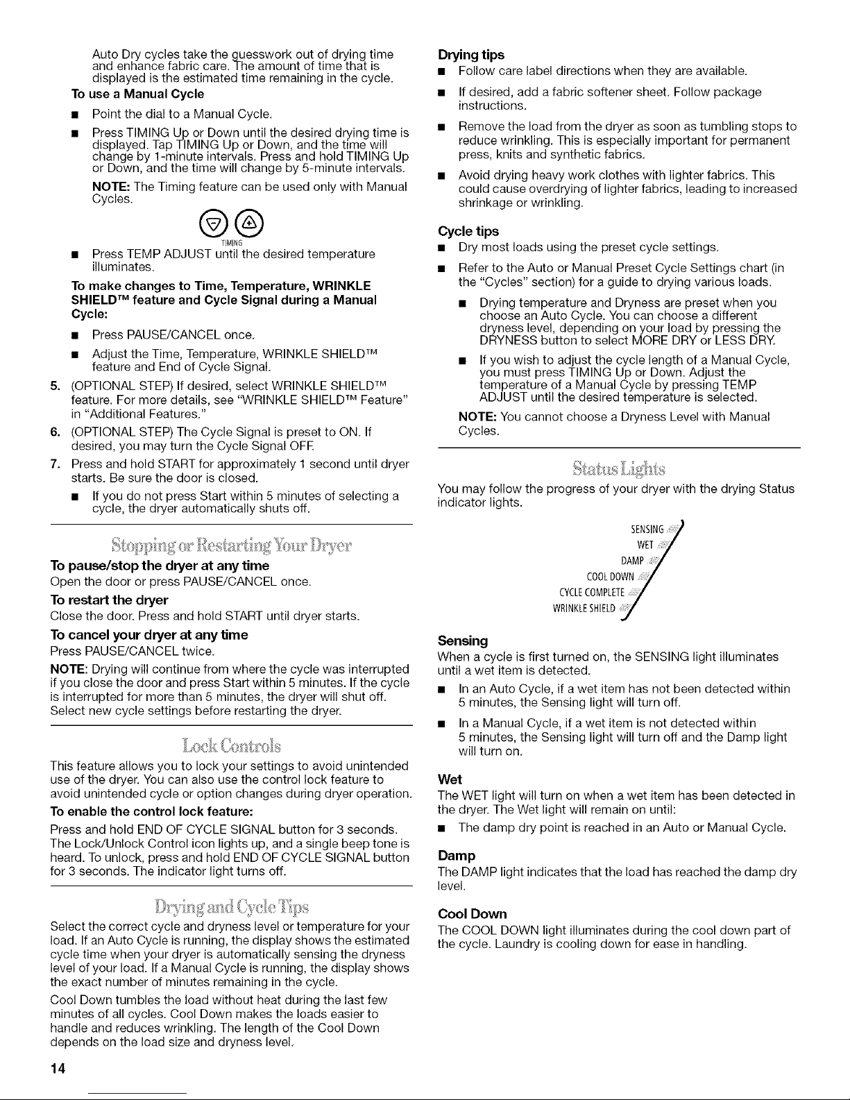
To use a Manual Cycle
• Point the dial to a Manual Cycle.
• Press TIMING Up or Down until the desired drying time is
displayed. Tap TIMING Up or Down, and the time will
change by 1-minute intervals. Press and hold TIMING Up
or Down, and the time will change by 5-minute intervals.
NOTE: The Timing feature can be used only with Manual
Cycles.
@®
TIMING
• Press TEMP ADJUST until the desired temperature
illuminates.
To make changes to Time, Temperature, WRINKLE
SHIELD TM feature and Cycle Signal during a Manual
Cycle:
• Press PAUSE/CANCEL once.
• Adjust the Time, Temperature, WRINKLE SHIELD TM
feature and End of Cycle Signal.
5. (OPTIONAL STEP) If desired, select WRINKLE SHIELD TM
feature. For more details, see "WRINKLE SHIELD TM Feature"
in "Additional Features."
6. (OPTIONAL STEP) The Cycle Signal is preset to ON. If
desired, you may turn the Cycle Signal OFE
7. Press and hold START for approximately 1 second until dryer
starts. Be sure the door is closed.
• If you do not press Start within 5 minutes of selecting a
cycle, the dryer automatically shuts off.
To pause/stop the dryer at any time
Open the door or press PAUSE/CANCEL once.
To restart the dryer
Close the door. Press and hold START until dryer starts.
To cancel your dryer at any time
Press PAUSE/CANCEL twice.
NOTE: Drying will continue from where the cycle was interrupted
if you close the door and press Start within 5 minutes. If the cycle
is interrupted for more than 5 minutes, the dryer will shut off.
Select new cycle settings before restarting the dryer.
This feature allows you to lock your settings to avoid unintended
use of the dryer. You can also use the control lock feature to
avoid unintended cycle or option changes during dryer operation.
To enable the control lock feature:
Press and hold END OF CYCLE SIGNAL button for 3 seconds.
The Lock/Unlock Control icon lights up, and a single beep tone is
heard. To unlock, press and hold END OF CYCLE SIGNAL button
for 3 seconds. The indicator light turns off.
Drying tips
• Follow care label directions when they are available.
• If desired, add a fabric softener sheet. Follow package
instructions.
• Remove the load from the dryer as soon as tumbling stops to
reduce wrinkling. This is especially important for permanent
press, knits and synthetic fabrics.
• Avoid drying heavy work clothes with lighter fabrics. This
could cause overdrying of lighter fabrics, leading to increased
shrinkage or wrinkling.
Cycle tips
• Dry most loads using the preset cycle settings.
• Refer to the Auto or Manual Preset Cycle Settings chart (in
the "Cycles" section) for a guide to drying various loads.
Drying temperature and Dryness are preset when you
choose an Auto Cycle. You can choose a different
dryness level, depending on your load by pressing the
DRYNESS button to select MORE DRY or LESS DRY.
• If you wish to adjust the cycle length of a Manual Cycle,
you must press TIMING Up or Down. Adjust the
temperature of a Manual Cycle by pressing TEMP
ADJUST until the desired temperature is selected.
NOTE: You cannot choose a Dryness Level with Manual
Cycles.
You may follow the progress of your dryer with the drying Status
indicator lights.
SENSING
WET_
DAMP/
COOLDOWN
CYCLECOMPLETE_/
WRINKLESHIELD_1
Sensing
When a cycle is first turned on, the SENSING light illuminates
until a wet item is detected.
• In an Auto Cycle, if a wet item has not been detected within
5 minutes, the Sensing light will turn off.
• In a Manual Cycle, if a wet item is not detected within
5 minutes, the Sensing light will turn off and the Damp light
will turn on.
Wet
The WET light will turn on when a wet item has been detected in
the dryer. The Wet light will remain on until:
• The damp dry point is reached in an Auto or Manual Cycle.
Damp
The DAMP light indicates that the load has reached the damp dry
level.
Select the correct cycle and dryness level or temperature for your
load. If an Auto Cycle is running, the display shows the estimated
cycle time when your dryer is automatically sensing the dryness
level of your load. If a Manual Cycle is running, the display shows
the exact number of minutes remaining in the cycle.
Cool Down tumbles the load without heat during the last few
minutes of all cycles. Cool Down makes the loads easier to
handle and reduces wrinkling. The length of the Cool Down
depends on the load size and dryness level.
14
Cool Down
The COOL DOWN light illuminates during the cool down part of
the cycle. Laundry is cooling down for ease in handling.
 Loading...