

Page 1
Instructions for installation,
use and maintenance
GAS COOKER
AGB 579/WP
AGB 580/WP
AGB 583/WP
AGB 584/WP
024_03
07/2007
VALIDITY FROM SERIAL NUMBER 0627005545
Page 2
024-03 - Gas cooker
2
Validity from serial number 0627005545
Models and dimensions page 3
Data of appliances 5
Technical data 5-6
Operating instructions 7
Construction, equipment installed
and safety devices 7
Cooking top (gas) 7
Gas oven 7
Gas version GN 1/1 7
Assembly 7
Location 7
Legal and technical requisites 7
Installation 7
Installation procedure 7
Connecting the gas supply 7
Gas venting 7
Wiring 8
Unipotential 8
Commissioning the appliance 8
Before commissioning the appliance 8
Start-up 8
Testing the power rating 8
Checking input pressure 8
Checking power rating using
the volumetric method 8
Checking power rating when using
LP gas 9
Checking the primary air 9
Checking the functions 9
Note for the installer 9
Running the appliance on other types
of gas 9
Replacing the gas rings nozzles 9
Replacing the oven nozzle 9
Adjusting the primary air 9
Replacing the nozzle of gas oven GN 1/1 9
Adjusting the low flame of the gas rings 9
Adjusting the low flame of the oven 9
Maintenance page
10
Replacing parts 10
Gas ring ignition plung 10
Gas ring tap 10
Gas ring thermocouple 10
Oven ignition plug 10
Oven gas tap 10
Oven thermocouple 10
Plug of ventilated gas oven 10
Ventilated gas oven gas valve 10
Ventilated gas oven thermocouple 10
Ventilated gas oven main burner 10
Fan for gas ovens GN 1/1 10
Solid top gas valve 10
Solid top thermocouple 10
Solid top ignition plug 10
Using the appliance 13
Start-up 13
Turning a burner on and off
(cooking top) 13
Turning the gas oven on and off 13
Switching the oven light 13
Turning on ventilated gas oven GN 1/1 13
Temperature adjustment in gas oven GN 1/1 13
Turning the appliance off in
an emergency 13
What to do if something goes wrong or if
not using the appliance for a long time 13
Taking care of the appliance frequency of maintenance 14
WEEE Directive 15
Warning 16
INDEX
Page 3
024-03 - Gas cooker
3
Validity from serial number 0627005545
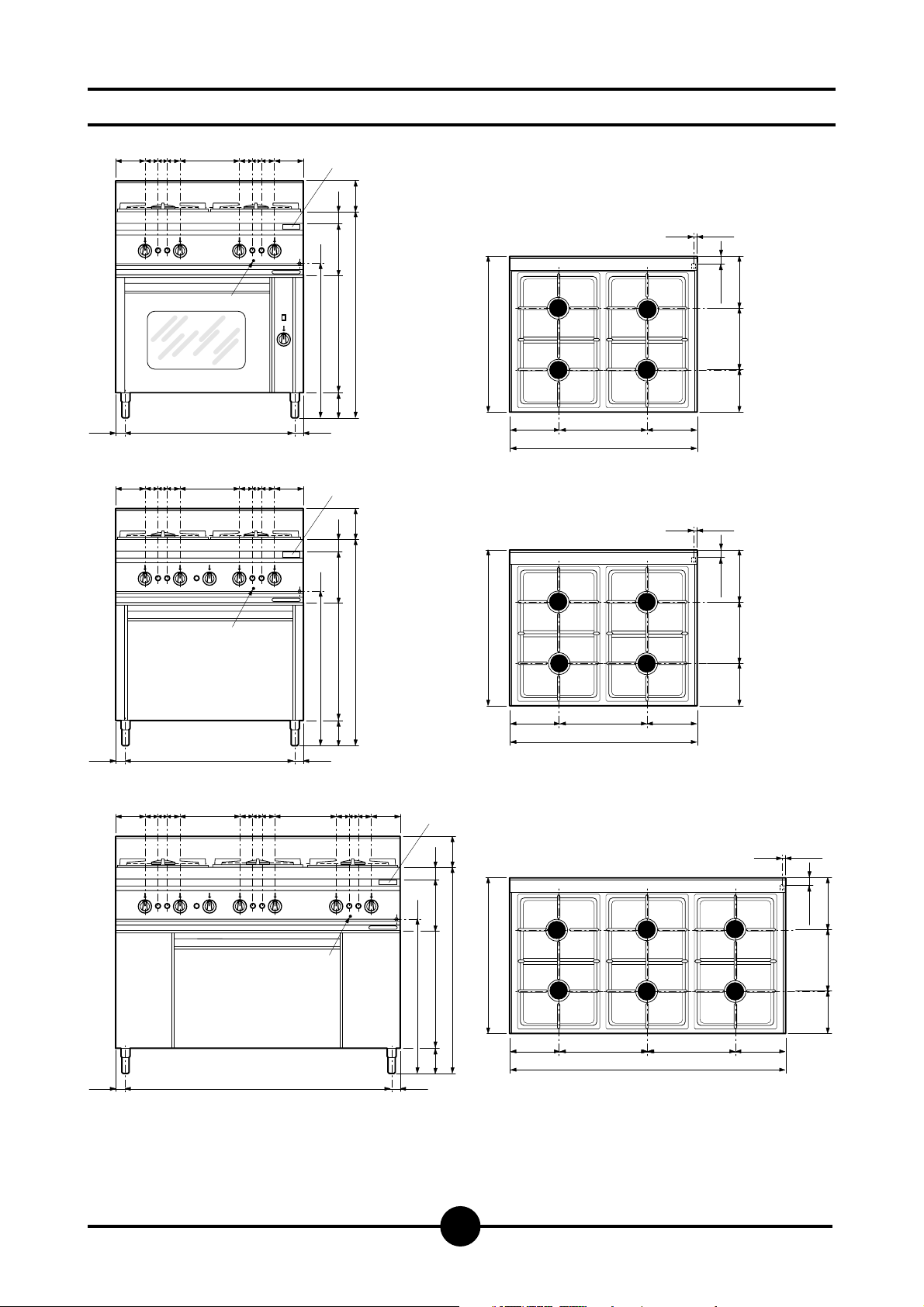
Dimensions
125 125
55 40 55 55 40 55
T
130
Bruciatore:
ø 100
C
37,5
725
AGB 579/WP
125 125
55 40 55 55 40 55
13.5
±1
G
±2
35
260 215
180
G
G
220 50
A
±1
655
37,5
875
465140
655
C
C
C
C
400 200200
800
T
13.5
±1
G
±2
35
260 215
180
130
G
220 50
C
A
±1
655
875
465140
655
C
G
C
C
37,5
725
AGB 580/WP
125 125
55 40 55 55 40 55
37,5
55 40 55
1125
AGB 583/WP
Off-take
A
Gas connection
G
Data plate
T
37,5
400 200200
800
T
13.5
±1
G
±2
35
260 215
180
130
G
220 50
C
C
A
±1
465140
655
37,5
875
655
C
C
C
400200
1200
400 200
G
C
C
Page 4
024-03 - Gas cooker
4
Validity from serial number 0627005545
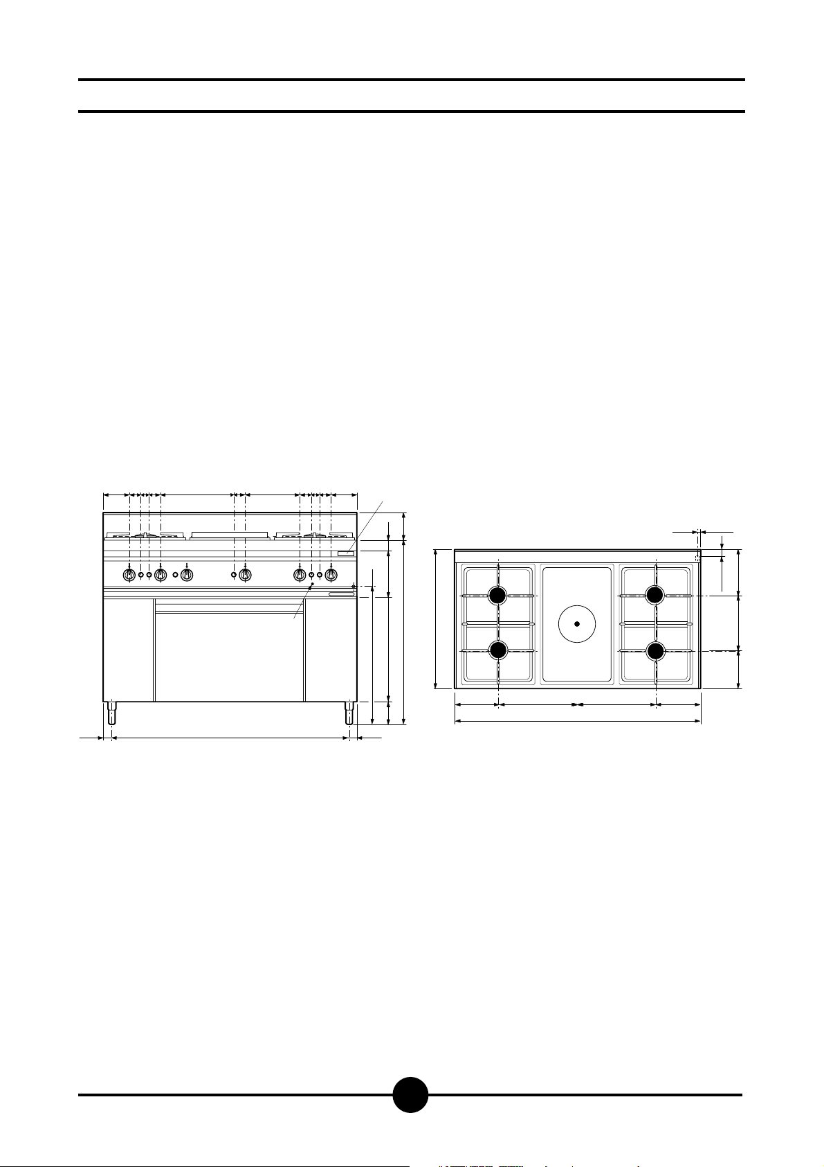
Dimensions
125 125
55 40 55 55 40 55
37,5
55
1125
AGB 584/WP
130
875
Bruciatore:
ø 100
C
655
13.5
±1
G
±2
35
260 215
180
G
C
C
C
400200
1200
C
C
400 200
T
G
220 50
A
±1
465140
655
37,5
Off-take
A
Gas connection
G
Data plate
T
Page 5
024-03 - Gas cooker
5
Validity from serial number 0627005545
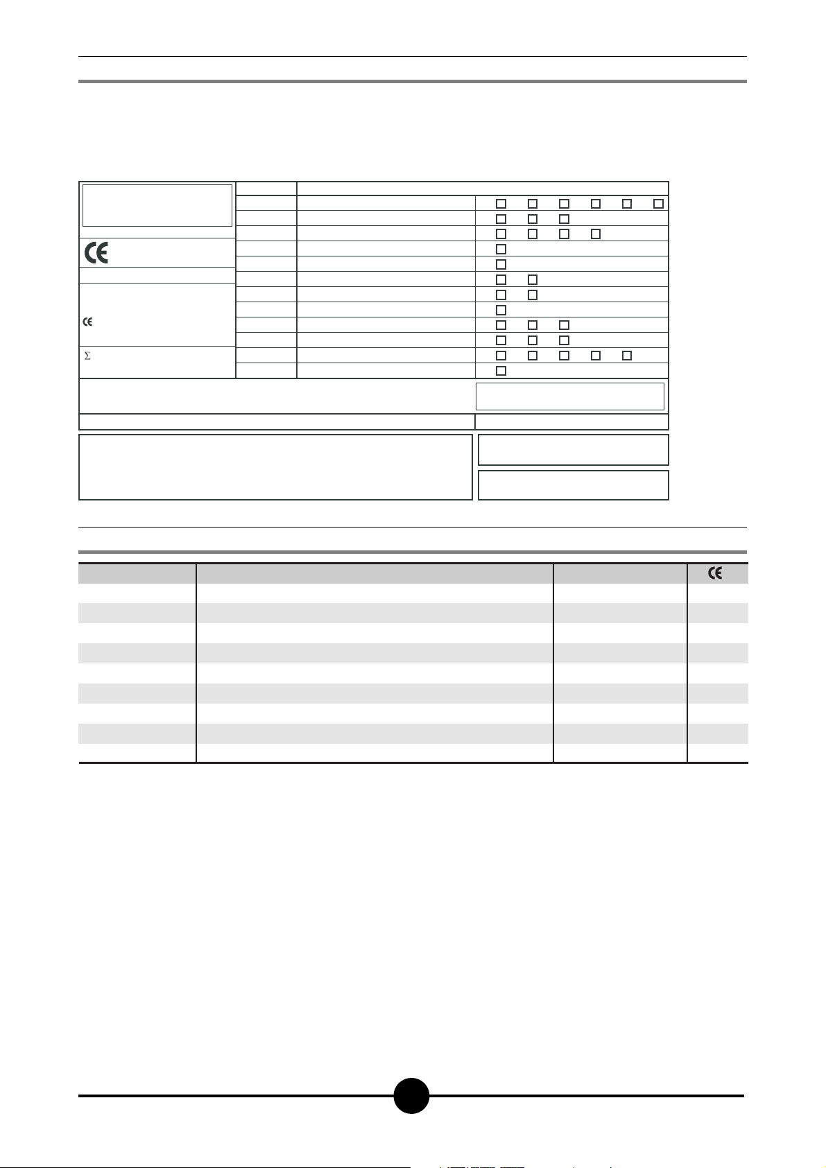
2 - CHARACTERISTICS OF THE APPLIANCES
3 - TECHNICAL DATA
These appliances are used for professional purposes. Installation, repair and use must be carried out by expert personnel.
These instructions for installation are for our gas kitchens set up for
the category in the table on page 6. The data plate is located on the
front part of the appliance (on the control panel).
CAT/KAT GAS/GAZ G30 G31 G20 G25
II2H3B/P P mbar 30 30 20 -
II2H3+ P mbar 30 37 20--
II2H3+ P mbar 28 37 20 -
0051
TIPO/TYPE
MOD.
ART.
N.
N.
Qn kW
MOD.
V AC kW Hz
THE APPLIANCE MUST BE CONNECTED IN COMPLIANCE WITH THE LAWS IN FORCE
AND INSTALLED IN A WELL-VENTILATED ROOM. READ THE INSTRUCTION MANUALS
BEFORE INSTALLING AND USING THE APPLIANCE.
THE APPLIANCE MUST BE INSTALLED BY QUALIFIED PERSONNEL.
m3/h
II2ELL3B/P P mbar 50 50 20 20
II2E+3+ P mbar 28 37 20 25
II2H3B/P P mbar 50 50 20 -
I2E P mbar - - 20 -
--II2H3B/P P mbar 30 30
II2H3+ P mbar 28 37 20 -
I3B/P P mbar 30 30
I3+ P mbar 28 37
Predisposto a gas: - Gas preset: - Prevu pour gaz:
Eingestelt für Gas: - Preparado para gas: -
--
--
Geschuckt voor:
SE FI DK CZ SK SI
IT CH PT
ES IE GB GR
NL
25II2L3B/P P mbar 30 30
DE
FR BE
AT CH
LU
EE LV LT
EE LV LT
NO MT CY IS HU
CY
MADE IN ITALY
G30/G31 28/37 mbar
G20 20 mbar
Model
AGB 579/WP
AGB 580/WP
AGB 583/WP
AGB 584/WP
Description
4 burners - 1 gas oven GN 2/3
4 burners - 1 gas oven GN 1/1 ventilated
6 burners - 1 gas oven GN 1/1
2+2 burners - Solid Gas range - 1 gas oven GN 1/1 enameled
Dimensions in mm. (LxPxH)
800 x 650 x 875/1005
800 x 650 x 875/1005
1200 x 650 x 875/1005
1200 x 650 x 875/1005
N.
51BQ2895
51BQ2895
51BQ2895
51BQ2895
Page 6

Primary air distance “A”
Methane gas G20
Liquid gas G30/G31
TABLE 1
Model
Category
Construction type
Air necessary for combustion
Nominal thermal power
Minimum thermal power
Overall thermal power (gas)
Connection pressure
Methane gas 2H
Liquid gas 3+
Gas connection values
Methane gas 2H
Liquid gas 3+
Nozzles Ø 1/100 mm
Main burner
G20
G30/G31
(HuB = 9.45 kWh/m
3
) in m3/h
(HuB = 12.87 kWh/kg) in kg/h
Nominal thermal power
Minimal thermal capacity
Nominal thermal power
Minimal thermal capacity
G20
G30/31
20 mbar
28/37 mbar
II2H3+
A
m
3
/h
kW
kW
No. of nozzles, pilot burner
G20
G30/G31
Electrical data Electric oven power: Voltage: No. of cables per section:
Hour consumption
G20
m3/h
G25
m3/h
G30/G31
kg/h
8
1
B
Ø 75
5
2.5
0.7
0.265
0.196
95
Adjustable
67
40
-
-
8
3
C
Ø 100
7
3.5
0.9
0.370
0.274
0.635
0.470
145
Adjustable
95
40
-
-
9
Open
185
Adjustable
125
75
27
19
-
-
Gas oven
GN 1/1
6.0
3.0
1.4
0.317
0.235
135R
Adjustable
85
70
-
-
Open
Open
Gas oven
GN 1/1
ventilated
7.5
3.6
0.75
0.381
0.282
155
Adjustable
100
48
-
-
-
-
Gas oven
GN 2/3
5
2.2
0.8
0.233
0.172
115R
Adjustable
75
48
-
-
CC80G 40 W
73 W
V 230 3 50 Hz
V 230 3 50 Hz
3 x 1.5 mm
2
3 x 1.5 mm
2
-
-
-
kW
kW
kW
kW
Solid
Gas range
12
6.0
1.8
AGB 579/WP
AGB 580/WP
AGB 583/WP
AGB 584/WP
16.2
17.6
24.6
20.5
1,71
1,86
2,60
2,17
1,27
1,38
1,92
1,60
024-03 - Gas cooker
6
Validity from serial number 0627005545
Page 7

024-03 - Gas cooker
7
Validity from serial number 0627005545
Construction, equipment installed and
safety devices
Robust steel frame, with 4 legs (adjustable in height).
18/10 chrome-nickel steel outer panelling.
Cooking top (Gas)
- Each position has a burner with a flame distributor.
- Max-min safety gas taps.
- Thermocouple.
- Each position has independent piezo ignition.
- Enamelled cast-iron pan supports.
- Plastic control knobs.
Gas oven
- Acid-proof enamelled sheet-steel muffle; steel grill support pair, removable for cleaning.
- Acid-proof enamelled sheet-metal floor.
- Extractable chromium-plated steel grill.
- Heat-insulated double-thickness door with heat-proof
glass window (only AGB 579/WP, the door of the
AGB 580/WP and AGB 583/WP gas ovens is solid); on
sprung hinges; insulated handle.
- Door and muffle insulated with spun glass.
- Thermostatic safety tap, temperature regulation
100 ÷ 275°C.
- Thermocouple
- Oven interior light (only AGB 579/WP) switch.
Gas version GN 1/1 ventilated
- The tubular burners are in stainless steel and are resistant to thermal and mechanical stress.
- Gas is supplied through a safety valve with a thermostat
and a safety thermocouple.
- The ignition of the main burner takes place by means of
an AT transformer.
- The adjustment of the oven temperature, which can be
varied between 160 and 300° C, is made with the thermostat.
- The bottom of the oven is made of stainless steel.
- The smoke collector is in aluminised sheet metal.
ASSEMBLY
Location
The appliance should be installed in a well ventilated
room, and if possible under a range hood.
The appliance can be installed on its own or alongside
other equipment.
If the appliance is to be installed near inflammable walls, a
minimum distance of 150 mm around the sides and back
should be allowed.
If this is impossible, take proper steps to ensure the installation is safe, such as fitting tiles or heat-reflecting material
to the walls
Before connecting up the appliance to the gas supply,
check on the data plate that the appliance is fitted for the
type of gas available.
If not, consult paragraph “Running the appliance on other
types of gas”, page 9.
Legal and technical requisites
During assembly, the following legal and technical requisites should be adhered to:
- relevant national legislation;
- local building and fire safety regulations;
- worksheet “Technical rules for installing gas”;
- worksheet “Technical rules for LP gas”;
- worksheet “Gas installations in industrial kitchens”;
- industrial injury legislation;
- local Gas Board regulations;
- current CEI regulations.
INSTALLATION
Assembly, installation and maintenance, i.e.:
- assembly, connecting the gas supply, checking power
rating, transforming or adapting the appliance to run on
other types of gas, and commissioning,
- connecting the appliance to the mains, must all be done by contractors authorised by the local Gas and
Electricity Boards in accordance with local and national
legislation.
Before doing anything else, seek advice from your Gas
and Electricity Boards.
Installation procedure
To level the appliance correctly, adjust the height of the
four legs. The R 1/2” gas off-take on the appliance can
either be permanently fixed to the mains or made detachable using a standard adaptor.
If flexible hose is used, it must be in stainless steel and to
current regulations.
After completing connection, check for leaks using a special leak-detector spray.
Gas venting
These appliances are A construction type, thus no gas
venting is required.
For advice on ventilating the premises where the appliance
is installed, observe current regulations.
OPERATING INSTRUCTIONS
Page 8

024-03 - Gas cooker
8
Validity from serial number 0627005545
Before commissioning the appliance
Before commissioning the appliance, remove the protective wrapping.
Start-up
Before starting the appliance up, check that its specifications (category and type of gas used) match those of the
family and group of the gas available locally.
If not, adapt the appliance to the gas family or group required (see paragraph “Running the appliance on other
types of gas”, page 9).
To start the appliance up, see the instructions for regular
use.
Testing the power rating
Use the specific nozzles for the nominal capacity on the
appliance.
Capacity can be of two types:
- nominal, as given on the data plate;
- minimum.
These nozzles are shown in “TECHNICAL DATE” table 1.
The following are the operating pressure tolerances to obtain the nominal power according to the agreed nozzles:
- from 15 to 22.5 mbar for gases of the second family
- from 25/35 to 35/40 mbar for gases of the third family
(Butane-Propane).
The appliance will not work outside the above pressure thresholds.
To adjust the capacity to its minimum value, use the data
in tables 1.
If you wish to check the nominal capacity further, you may
do so using a gas meter according to the so-called ”volumetric method”. It is normally enough, however, simply to
check that the nozzles are functioning correctly.
Checking input pressure (Fig. 2)
Input pressure should be measured using a gauge (e.g. a
gooseneck pipe, min. resolution 0.1 mbar).
Remove screw (F) from the pressure socket and connect it
to the tube on the gauge; after measuring, the screw
should be retightened absolutely airtight (F).
Checking power rating using the
volumetric method
Using a gas meter and a chronometer, you can read the
volume of gas output per time unit.
The correct volume will be the value of “E” expressed in litres per hour (It/hr) or litres per minute (It/min).
The following formula is used to calculate the value of “E”:
Capacity should only be measured when the appliance is
at a standstill.
The heat value can be obtained from your local Gas
Board. To obtain the nominal and minimum capacities in
relation to the nominal pressure, consult table 1.
Capacity
Heat value
E =
COMMISSIONING THE APPLIANCE
Wiring
Before connecting the appliance to the electricity supply,
check the following:
- make sure the mains supply voltage matches the value
on the data plate;
- make sure the appliance is properly earthed.
- Make sure the shielding of the connections can stand
up to the nominal capacity.
Also an omnipolar switch with at least a 3 mm. contact
aperture should be installed upstream of the appliance,
so that it can be completely disconnected from the mains.
Compulsort automatic safety switches can be used for
this purpose. The omnipolar switch must be located near
the appliance and easy to reach.
The connecting cable used for the appliance must be
suited in section to the particular version and to its nominal capacity. Use an H07-RN-F type cable for oven G
(static).
Use an H05BB-F/T90 type cable for oven CG (ventilation).
Unipotential
The appliance must be connected up to a unipotential system. A connection terminal marked “unipotential” is provided for this purpose on the underside of the appliance,
near the lead-wire entry area.
Page 9

024-03 - Gas cooker
9
Validity from serial number 0627005545
WARNING
It is not possible to adjust nominal capacity in advance.
Checking power rating when using LP
gas
Check that the type of nozzles used match manufacturer's
specifications.
Check that the output pressure regulator installed collaterally to the plant conforms to the specifications laid down
in paragraph "Checking input pressure" (see data plate or
measure the pressure).
Checking the primary air
The primary air in the open burners can not be adjusted.
Checking the functions
- Start the appliance in accordance with the instructions;
- Check the gas tubes for leaks;
- Check that the flame on the main burner lights properly
and is correctly formed, even on low;
- Draw up a servicing and maintenance contract.
Note for the installer
- Explain and demonstrate to the user how the machine
works according to the instructions, and hand him this
manual.
- Remind the user that any structural alterations to the
room housing the appliance may affect the combustion
air supply. Once the alterations have been completed,
the appliance and its functions should be thoroughly
checked.
Running the appliance on other types
of gas
When changing to another type of gas, e.g. from natural to
LP, or to another gas group, consult the “TECHNICAL DATA” table to make sure you use the appropriate nozzlzes
for the main burner.
The nozzles for the cooking top burners for different types
of gas, marked in 100ths of mm, are in a case supplied
with the appliance. If injectors are not available please
contact the factory with model and serial number written
on technical data sticker.
When the appliance has been transformed or adapted, recheck its functions as described in paragraph "Checking
the functions".
Replacing the gas ring nozzles (Fig. 2)
To change nozzle (C), remove the knobs and loosen the
control panel fixing screws.
Remove the control panel, disconnect the ignition lead
and unscrew the nozzle from the nozzle holder with a
spanner.
Replace with a new nozzle (see “TECHNICAL DATA” table.
After fitting the nozzle, reset primary air distance “A” (see
“TECHNICAL DATA” table).
Replacing the oven nozzle (Fig. 3)
To gain access to the oven burner, remove the oven floor
(from inside the oven cavity).
Remove screws D (Fig. 3) and remove the burner by pulling it forwards; using the special spanner, unscrew the
injector C (Fig. 3) and replace it with the correct one for
the type of gas.
Replace the burner, following the above procedure in the
reverse order.
Adjusting the primary air
Light the burner and inspect the flame; if necessary, adjust the air as follows:
Loosen screw D (Fig. 3), move the burner in the direction
necessary to obtain a steady, even flame.
Replacement of nozzle of gas oven
GN 1/1 ventilated (Fig. 2B)
After opening the door, remove the grill, the grill supports
and the stainless steel bottom, then unscrew the protection form the nozzle zone.
Remove the air adjustment by unscrewing screw (2). The
nozzle is now accessible. Replace it with one that is suitable for the type of gas to be used. See the table "TECHNICAL DATA". After replacement, reassemble everything
and perform air adjustment (see the table "TECHNICAL
DATA").
Adjusting the low flame of the gas
rings (Fig. 2)
Referring to the “TECHNICAL DATA” table, set the low flame screw (D) as follows:
- if the appliance is to run on LP gas, tighten the low flame screw as far as it will go;
- if the appliance is to run on natural gas, turn the low flame screw:
● read off the setting in It/min which corresponds to
the heat value (calculated by the “Volumetric Method”)
in the Gas Flow Setting Table (2);
● start the appliance up according to the instructions;
● after allowing the appliance to run for 45 minutes,
turn the knob to low and set minimum by turning screw
(20) (to the right = gas flow decreases; to the left =
gas flow increases).
Adjust the gas flow.
Adjusting the low flame of the oven
(Fig. 3)
Loosen screw H (Fig. 3) by two or three turns after having
removed the knob and the control panel cover. Light the
burner and keep it lit for at least 10 minutes with the knob
in the MAX position, then put the knob to Min and
tighten screw H until a reduced but steady, even flame is
obtained (the flame must warm the thermocouple even
on low).
Page 10

024-03 - Gas cooker
10
Validity from serial number 0627005545
MAINTENANCE
The following maintenance programme should be carried
out at least once a year:
- Check that all the safety and setting devices are
working properly;
- Check that the burners are working properly with regard to:
- ignition
- combustion safety;
- Check the functions of the appliance as described in
paragraph "Checking the functions" page 9.
If the main burner needs cleaning, proceed as follows:
a ) Gas rings: remove the pan support, the flame distri-
butor, the crown and the burner supports;
b) clean the parts with water and detergent, rinse and
dry;
c) when reassembling the parts, make sure you replace
them in the right order.
Cleaning the oven burner
To gain access to the oven burner, remove the floor (from
inside the oven cavity).
Remove screws D (Fig. 3) and remove the burner by pulling it forwards.
Clean the burner with water and detergent; to unblock the
holes, use a suitably sized prong.
REPLACING PARTS
All parts must be replaced by authorised technicians
only!
To replace the following parts first remove all the control
knobs and the control panel (after loosening the fixing
screws), then disconnect the ignition lead.
Gas ring ignition plug (Fig. 2)
Remove the pan support, the flame distributor, the crown
and the the burner crown support, pull out the spring
using a pointed tool, remove the ignition plug from the bottom, disconnect the ignition lead and insert a new plug.
Gas ring tap (Fig. 2)
Loosen the gas piping and thermocouple fixing screws,
then loosen the screws fixing the gas supply to the gas
ramp and insert a new tap.
Gas ring thermocouple (Fig. 2)
Loosen the screws fixing the thermocouple to the gas tap
and the burner. Insert the new part. After replacing the
parts, fit the control panel back into place.
Oven ignition plug (A - Fig. 3)
Remove the floor, unscrew the lock nut and the cable, insert the new ignition plug, making sure that the cable is reinserted correctly.
Oven gas tap (A - Fig. 3)
Loosen the nuts on the thermocouple and on the gas pipes, draw the thermostat bulb out from the supporting clips inside the oven cavity and replace the tap with a
new one.
Oven thermocouple (L - Fig. 3)
Remove the floor, unscrew the nut on the tap and the burner and replace the thermocouple.
After having disassembled the various pieces, the control
panel cover must be replaced.
Plug of ventilated gas oven
(Fig. 2B - Pos. 6)
Unscrew the fastening screws and remove the lower panel, extract the ignition wire and unscrew the screws (15).
Insert a new plug.
Ventilated gas oven gas valve (Fig. 3A)
Loosen the fittings (1,2,3,4 in fig. 3A and 1,2,3 in fig. 3B)
which are for the connection for the gas pipe and the thermocouple, remove the coil of the thermostat from its place
in the cooking chamber and put in a new piece in the reverse sequence.
Ventilated gas oven thermocouple
(Fig. 2B and 3)
Unscrew the screws (15) and the nut (16) for fastening the
thermocouple to the extension of thermocouple and insert
the new piece.
Ventilated gas oven main burner
(Fig. 2B)
Unscrew the fastening screw (19) of the main burner and
replace it with a new one. See also oven burner cleaning,
para. 6.7).
Fan for gas ovens GN 1/1 (Fig. 4A)
To replace the fan, remove the fan cover rear wall.
Remove the fan (1) by loosening the locking nut (2).
Loosen the bolts (3) that hold the plate (4) which supports
the motor (5) on the oven, pull the plate forward with the
motor and relative wires, remove and re-install in reverse
order.
Solid top gas valve (Fig. 5)
Loosen the fitting of the pipes (6) and (9) of the gas and of
the thermocouple (8), loosen the fitting (7) for the fastening of the valve on the ramp and replace the piece.
Solid top thermocouple (Fig. 5)
Loosen the nut (8) for fastening the thermocouple on the
valve and on the burner (19) and replace the piece (14).
Solid top ignition plug (Fig. 5)
The ignition plug (15) must be removed from below.
Disconnect the ignition lead, loosen the lock nut (19)and
insert a new plug.
Page 11

024-03 - Gas cooker
11
Validity from serial number 0627005545
WARNING
Every time a replacement involving gas input parts is
made, recheck all functions and test for leakage.
2
E
D
F
C
Page 12

024-03 - Gas cooker
12
Validity from serial number 0627005545
R
3
2B
4
3A
19
18
H
G
2
15
6
3
9
16
14
C
B
A
D
L
19
5
1
8
0
1
6
0
0
10
1
4
0
120
3
6
2
1
I
7
5
0
2
3
4
5
6
MAX
7
2
3
4
5
6
Page 13

START-UP
Turning a burner on and off cooking
top (Fig. 2) and solid top (Fig. 5)
Press the knob (H fig. 2) (21 fig. 5) and turn to the left as
far as .
Keep the knob pressed down while repeatedly pressing
the piezo ignition button (E fig. 2) (23 fig. 5) until the flame
catches.
Keep the knob pressed down for another 15-20 seconds:
if the flame goes out after the knob is released, start again.
To turn the burner off during normal operation,turn the
knob as far as (●).
Lighting and extinguishing the gas
oven (Fig. 4)
Lighting: open the oven door, press and turn the knob to
position 7 (Fig. 4) keeping it pressed down, press the push button marked .
The ignition spark lights the burner flame.
This operation may be observed through the hole in the
oven floor. Keep the knob pressed down for about 10" after ignition, so that the safety device activates.
Then adjust the thermostatic setting according to the
cooking programme required, taking into account that
the temperatures in relation to the knob positions are as
follows:
Position degrees °C
100
2 125
3 150
4 175
5 200
6 230
7 260
275
Should the piezo spark lighter not work properly, the oven
may be lit manually. After having opened the door, put a lit
match near the hole in the oven floor.
At the same time turn the knob counter-clockwise,keeping
it pressed down, to the thermostatic position 7.
Keep the knob pressed down for about 10"
Switching on the oven light.
Press the switch on the oven control panel (only AGB
579/WP).
Lighting ventilated gas oven GN 1/1
(Fig. 3B)
Turn on the switch located up the line from the unit. Press
the knob and turn it to the left until the spark position (5).
Hold the knob down and at the same time press the piezo
ignition button (6) repeatedly. Hold the knob down for 1520 seconds after the burner lights, which can be observed
through the hole in the bottom of the cooking chamber
(with the door open).
Temperature adjustment in gas oven
GN 1/1 (Fig. 3B)
To light the main burner, rotate the knob (5) to a position
from 2 to MAX, considering that the temperatures which
can be obtained are the following:
Position 234567MAX
Degrees °C 160 175 190 210 230 260 300
Shutdown
To shut off the main burner, turn the knob to the spark position. Only the pilot flame will remain lit. For complete
shutdown, turn the knob to position (0); in this position the
pilot burner also goes out.
Turning the appliance off in an
emergency
In an emergency turn off the appliance according to the
instructions; close the gas supply tap or disconnect the
power supply.
What to do if something goes wrong or if
not using the appliance for a long time
If the appliance is not to be used for a long time, or if it
breaks down or works incorrectly, close the tap to the gas
mains located outside the appliance and disconnect from
power supply.
If anything goes wrong, call the aftersales department.
USING THE APPLIANCE
024-03 - Gas cooker
13
Validity from serial number 0627005545
Page 14

024-03 - Gas cooker
14
Validity from serial number 0627005545
TAKING CARE OF THE APPLIANCE
FREQUENCY OF MAINTENANCE
Giving the appliance a thorough clean every day (after turning it off) will keep it in perfect working order and make it
last longer.
All steel parts should be cleaned with water and a detergent, using a damp cloth; do not use abrasive substances
or corroding detergents.
Do not use steel wool since this might cause rust to form.
For the same reason, avoid touching the appliance with
anything made of iron. Do not clean the appliance with
emery or sandpaper. If absolutely necessary, you may use
powdered pumice stone.
If the appliance is extremely dirty, use a synthetic sponge
such as Scotchbrite.
After cleaning the appliance, rinse with clean water and
dry with a cloth.
All maintenance work must be carried out by qualified personnel only.
Never clean the appliance with the jets of water,
whether direct or pressurised!
Have the appliance checked at least once a year; we
strongly recommend that you stipulate a servicing and
maintenance contract with your supplier.
mA
B1
MV
H2
Terminal board
Fan switch
Motorized fan
Indicator light
5
A
3
1
8
4
5
6
7
22
0
9
21
19
16
14
15
23
2
10
2 1 43
5
3
3
PE
Page 15

024-03 - Gas cooker
15
Validity from serial number 0627005545
THE 2002/96/EC DIRECTIVE (WEEE):
information to users
This informational note is meant only for owners
of equipment marked with the symbol shown in
Fig. A on the adhesive label featuring the technical specifications applied on the actual pro-
duct (the label also giving the serial number).
This symbol indicates that the product is classified, according to the regulations in force, as an item of electrical
and electronic equipment and conforms to EU Directive
2002/96/EC (WEEE) meaning that, at the end of its service
life, it must be treated separately from domestic waste,
i.e. it must be handed in free of charge to a separate waste electrical and electronic equipment collection centre
or returned to the reseller when buying a new equivalent
item of equipment.
The user is responsible for delivering the unit at the end of
its life to the appropriate collection facilities. Failure to do
so shall result in the user being subject to the penalties
prescribed by the legislation in force on waste.
Suitable separated collection so that the unit no longer
used can be sent off for environmentally compatible recycling, treatment and disposal helps avoid possible negative effects on the environment and on health and facilitates the recycling of the product's component materials.
For more detailed information on available collection systems, contact the local waste disposal service or the
shop you purchased the unit from.
Producers and importers fulfil their responsibility for environmentally compatible recycling, treatment and disposal
both directly and by joining a collective scheme.
Page 16

024-03 - Gas cooker
16
Validity from serial number 0627005545
WARNING
DUE TO ITS POLICY OF CONTINUAL PRODUCT IMPROVEMENT, THE MANUFACTURER RESERVES THE RIGHT
TO MAKE ANY CHANGES DEEMED NECESSARY.
THE MANUFACTURER CANNOT BE HELD RESPONSIBLE IF THE INSTRUCTIONS CONTAINED IN THIS MANUAL ARE NOT OBSERVED.
THIS DOCUMENTATION IS ONLY INTENDED FOR
QUALIFIED TECHNICIANS WHO ARE AWARE OF THE
RESPECTIVE SAFETY REGULATIONS.
WHIRLPOOL EUROPE srl
V.le Guido Borghi, 27
I – 21025 Comerio – VA
 Loading...