

Page 1
10T
10TR
14T
2/1
6T
10T 2/1
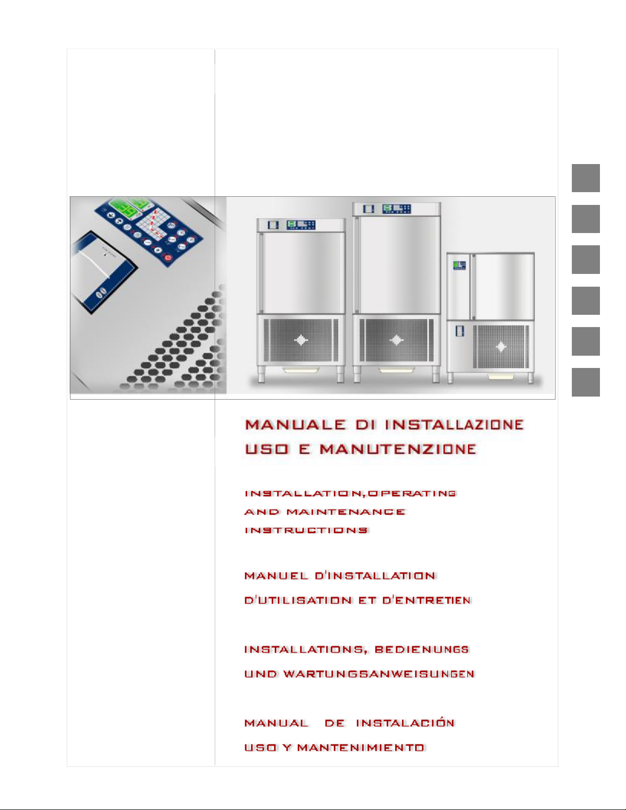
ABBATTI TORI e SURGELATORI
RAPIDI di TE MPERATURA
BLA ST C HILLER AND FRE E ZERS
SCH NELL K ÜHL E R CH OCKFR OSTE R
CELL ULE S DE REFR I GERA TION R APIDE E T
CON GELA TION
ABATI DOR E S – CONGE LADORES R A PIDO S DE
TEMP ERAT URA
IT
GB
FR
DE
ES
ADN 252
ADN 253
ADN 254
ADN 255
ADN 256
DESIGN SERIES
PT
Page 2

FR
IT
Il costruttore si riserva il diritto di modificare senza preavviso le caratteristiche delle apparecchiature presentate in
questa pubblicazione.
GB
The manufacturer reserves the right to modify the appliances presented in this publication without notice.
Le fabricant se réserve le droit de modifier sans préavis les caractéristiques des appareil présentés dans cette
publication.
DE
Der Hersteller behält sich das Recht vor, die in dieser Broschüre vorgelegten Geräte ohne Voranzeige zuändern.
ES
El constructor se reserva el derecho de modificar sin previo aviso las características de los equipos presentados
en esta publicación.
PT
O fabricante reserva-se o direito de modificar sem aviso prévio as características dos aparelhos apresentados
nesta publicação.
Page 3

ENGLISH
1. INDEX
1. INDEX............................................................................................................................................1
2. ANALYTICAL INDEX.....................................................................................................................2
3. REGULATIONS AND GENERAL INSTRUCTIONS........................................................................3
3.1. General information..............................................................................................................3
3.2. Warranty..............................................................................................................................3
3.3. Replacement of Parts...........................................................................................................3
3.4. Description of the Appliance.................................................................................................4
3.5. Features Plate......................................................................................................................5
4. SAFETY.........................................................................................................................................5
4.1. Safety Devices.....................................................................................................................6
5. USE AND FUNCTIONING..............................................................................................................7
5.1. Description of the Functioning Cycles...................................................................................7
5.2. Description of the Controls...................................................................................................8
5.3. Functionality.........................................................................................................................9
5.4. Recommendations for Use.................................................................................................13
6. CLEANING AND MAINTENANCE................................................................................................15
6.1. Recommendations for Cleaning and Maintenance..............................................................15
6.2. Routine Maintenance..........................................................................................................15
6.3. Extraordinary Maintenance 10T and 14T............................................................................15
6.4. Extraordinary Maintenance 10TR.......................................................................................17
6.5. Extraordinary Maintenance 6T 2/1......................................................................................19
6.6. Extraordinary Maintenance 10T 2/1....................................................................................21
7. TROUBLESHOOTING.................................................................................................................24
7.1. Faults Display.....................................................................................................................25
8. INSTALLATION............................................................................................................................25
8.1. Packaging And Unpacking..................................................................................................25
8.2. Installation..........................................................................................................................26
8.3. Electric Power Supply Connection......................................................................................27
8.4. Condensing unit water connection......................................................................................27
8.5. Remote condensing unit.....................................................................................................28
8.6. Inspection...........................................................................................................................29
9. DISPOSAL OF THE APPLIANCE.................................................................................................30
10. REFRIGERANT TECHNICAL CARD............................................................................................30
ATTACHMENTS................................................................................................................................. I
GB
1
Page 4

ENGLISH
2. ANALYTICAL INDEX
GB
B
Blast chilling Cycle; 14
C
Cleaning the condenser; 16; 18; 20; 22
Cleaning the evaporator; 16; 18; 20; 22
Condensing unit water connection; 27
D
Defrosting; 7
Description of the Appliance; 4
Description of the Controls; 7
Disposal of the Appliance; 30
Door micro switch; 6
E
Electric Power Supply Connection; 27
Evaporator Fan Micro switch; 6
F
FAULTS; 24
Faults Display; 25
Features Plate; 5
Fuse replacement and thermal relay rearm; 17;
19; 21; 23
G
General information; 3
I
Inspection; 29
Installation; 26
Intensive Blast Chilling Cycle; 14
Intensive timed blast chilling; 7
P
Packaging; 25
Preservation; 7
Prolonged Inactivity; 13
Protective Fuses; 6
R
Recommendations for Cleaning and Maintenance;
15
Recommendations for normal use; 13
Recommendations for Use; 13
REFRIGERANT TECHNICAL CARD; 30
Remote condensing unit; 28
Replacement of Parts; 3
Routine Maintenance; 15
S
SAFETY; 5
Safety Devices; 6
Shock freezing Cycle; 14
SOFT Time Shock Freezing; 7
T
Temperature Blast Chilling; 7
Temperature Blast Chilling (+90 à+3°C); 8
Temperature Shock Freezing; 7
Temperature Shock Freezing (+90 à-18°C); 10
Time Blast Chilling; 7
Time Blast Chilling (+90 à+3°C); 9
Time Shock Freezing; 7
Time Shock Freezing (+90 à-18°C); 10
U
U.V. Lamp Replacement; 17; 19; 21; 23
Unpacking; 25
W
Warranty; 3
2
Page 5

3. REGULATIONS AND GENERAL INSTRUCTIONS
3.1. General information
This manual has been designed by the
manufacturer to provide the necessary information
to those who are authorised to interact with the
appliance.
The persons receiving the information must read it
carefully and apply it strictly.
Reading the information contained in this
document will allow the user to prevent risks to
personal health and safety.
Keep this manual for the entire operating life of
the equipment in a place which is well-known and
easily accessible, so that it is always available
when its consultation becomes necessary.
3.2. Warranty
The warranty of the equipment and the
components we produce has duration of 1 (one)
year from the date of delivery and translates into
the supply, free of charge, of parts that we
consider to be faulty.
These faults must, however, be independent from
incorrect use of the product in compliance with the
indications stated in the manual.
3.3. Replacement of Parts
Particular symbols have been used to highlight
some parts of the text that are very important or to
indicate some important specifications. Their
meanings are given below: Caution - Warning
! Indicates important information regarding
safety. Behave appropriately so as not to risk
the health and safety of persons or cause
damage.
Important
iIndicates particularly important technical
information that must not be ignored.
Fees deriving from labour, journeys and transport
are excluded from the warranty.
The materials replaced under warranty are our
property and must therefore be returned under the
responsibility and expense of the customer.
ENGLISH
GB
! Activate all envisioned safety devices before
carrying out any replacement intervention.
iIn particular, deactivate the electrical power
supply using the differential isolating switch.
Only use original spare parts to replace worn
components.
iAll responsibility is declined for injury to
persons or damage to components deriving from
the use of non-original spare parts and
interventions which could modify the safety
requisites, without authorisation of the
manufacturer.
3
Page 6
GB
1 3 - 4
A 2
ENGLISH
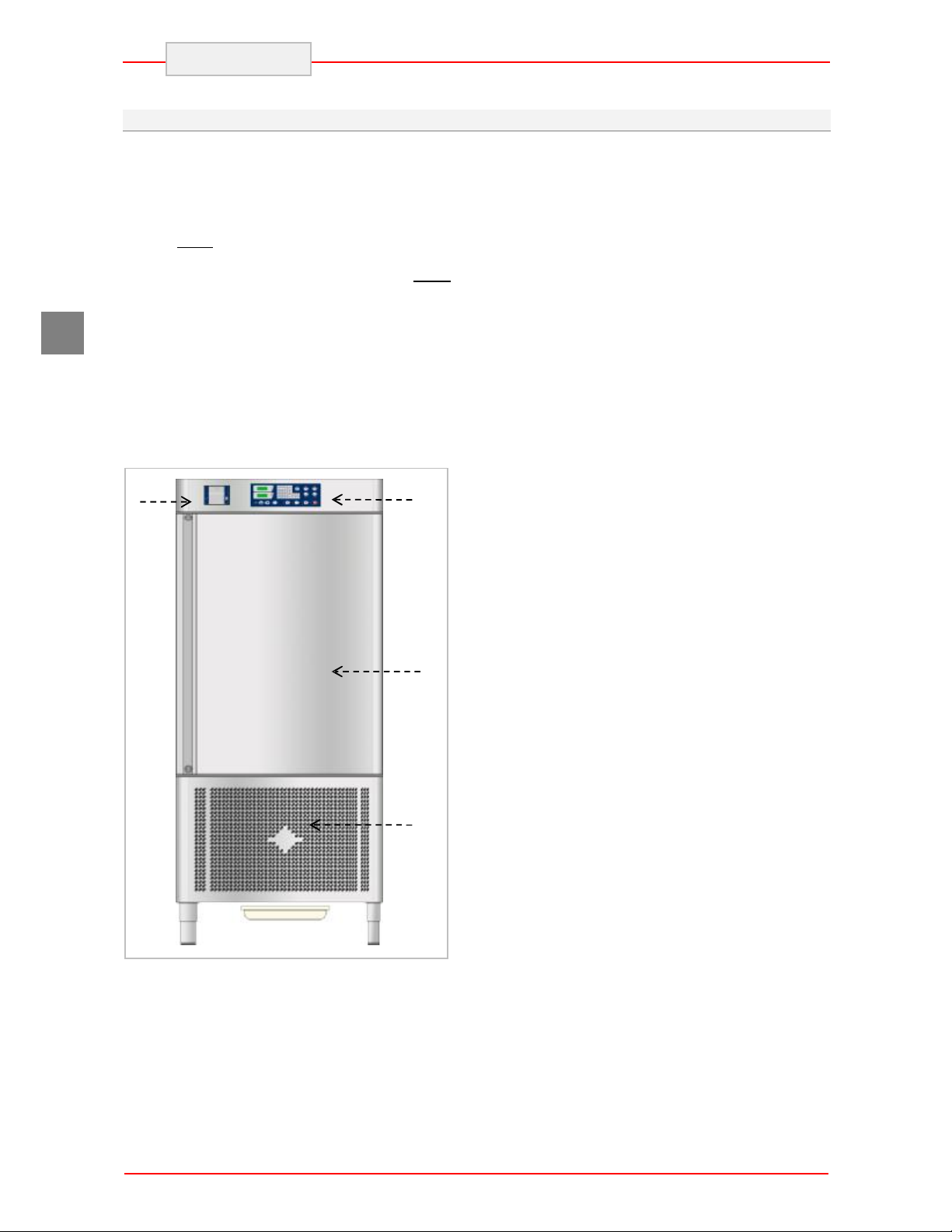
3.4. Description of the Appliance
The Blast chiller-Shock freezer, from now on
defined as appliance, has been designed and built
to cool and/or freeze foodstuffs in the professional
catering ambit.
1) condensation area: it is positioned in the
lower part and is characterised by the
presence of the condensing unit.
2) electric area: it is positioned in the upper
part of the appliance and contains the
control and power supply appliance as
well as electric wiring.
3) evaporation area: it is situated inside the
refrigerated compartment in the rear and
is characterised by the evaporating unit.
4) storage area: it is situated inside the
refrigerated compartment and is destined
for the cooling and/or freezing of
foodstuffs.
The lower part is also distinguished by a control
panel (A) that allows access to the electric parts;
there is a vertically-opening door in the front,
which closes the refrigerated compartment
hermetically.
Depending on requirements, the appliance is
produced in several versions.
10 TRAY BLAST CHILLER-SHOCK FREEZER
Model suitable to contain 10 trays with
blast chilling capacity of 40 kg.
10 TRAY BLAST CHILLER and SHOCK
FREEZER
Model suitable to contain 10 trays with
blast chilling capacity of 40 and 25 in
shock freezing.
10 T "R" BLAST CHILLER and SHOCK
FREEZER
Model suitable to contain 10 “insertion
325” trays with blast chilling capacity of 40
and 25 in shock freezing.
14 TRAY BLAST CHILLER-SHOCK FREEZER
Model suitable to contain 14 trays with
blast chilling capacity of 55 kg.
14 TRAY BLAST CHILLER and SHOCK
FREEZER
Model suitable to contain 14 trays with
blast chilling capacity of 55 and 35 in
shock freezing.
6T 2/1 BLAST CHILLER and SHOCK FREEZER
Model suitable to contain 6
GASTRONORM 2/1trays with blast
chilling capacity of 50 and 30 in shock
freezing.
10 TRAY 2/1 BLAST CHILLER
Model suitable to contain 10
GASTRONORM 2/1 trays with blast
chilling capacity of 75 kg.
10T 2/1 BLAST CHILLER and SHOCK
FREEZER
Model suitable to contain 10
GASTRONORM 2/1trays with blast
chilling capacity of 75 and 50 in shock
freezing.
4
Page 7
2 3 4 5 6 7 8
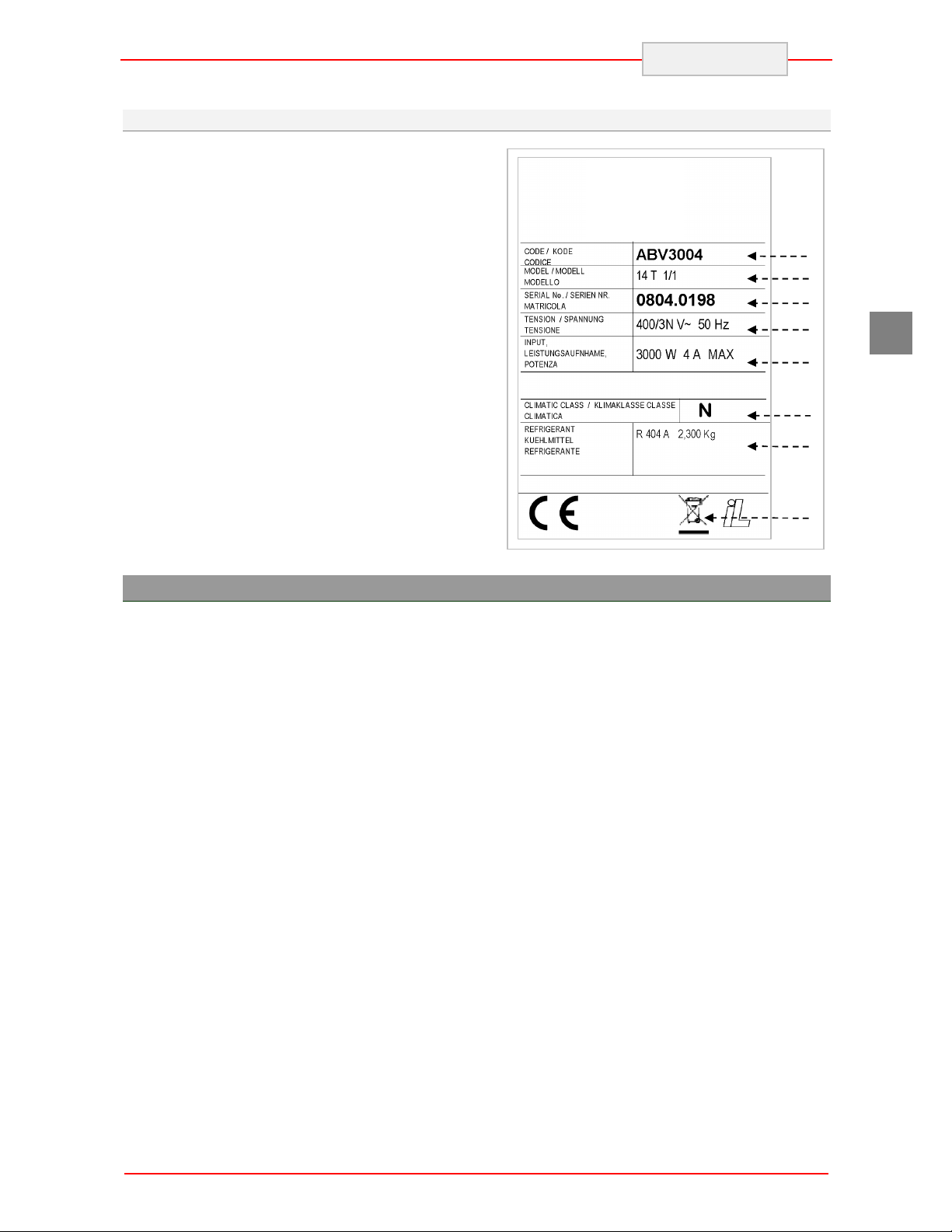
3.5. Features Plate
The identification plate shown is applied directly
onto the appliance. It states the references and all
indications indispensable for working in safety.
1) Appliance code
2) Description of the appliance
3) Serial number
4) Power supply voltage and frequency
5) Electrical absorption
6) Climatic class
7) Type and Amount of refrigerant gas
8) WEEE symbol
ENGLISH
1
GB
4. SAFETY
iIt is recommended to carefully read the
instructions and warnings contained in this
manual before using the appliance. The
information contained in the manual is
fundamental for the safety of use and for machine
maintenance.
! Keep this manual carefully so that it can be
consulted when necessary.
i The electric plant has been designed in
compliance with the IEC EN 60335-2-24
Standard.
, Specific adhesives highlight the presence of
mains voltage in the proximity of areas (however
protected) with risks of an electrical nature.
! Before the connection, ensure the presence of
an omnipolar switch with minimum contacts
opening equal to 3 mm in the mains power supply
upstream from the appliance (requested for
appliances supplied without plug to connect to the
fixed plant).
In the design and construction phase, the
manufacturer has paid particular attention to the
aspects that can cause risks to safety and health
of persons that interact with the appliance.
Carefully read the instructions stated in the
manual supplied and those applied directly to the
machine, and particularly respect those regarding
safety.
Do not tamper or eliminate the installed safety
devices. Failure to comply with this requisite can
lead to serious risks for personal health and
safety.
It is recommended to simulate some test
manoeuvres in order to identify the controls, in
particular those relative to switch-on and switchoff and their main functions.
The appliance is only destined for the use for
which it has been designed; any other use must
be considered improper.
iThe manufacturer declines all liability for any
damage to objects or injury to persons owing to
improper or incorrect use.
i All maintenance interventions that require
precise technical skill or particular ability must be
performed exclusively by qualified staff.
5
Page 8
GB
ENGLISH
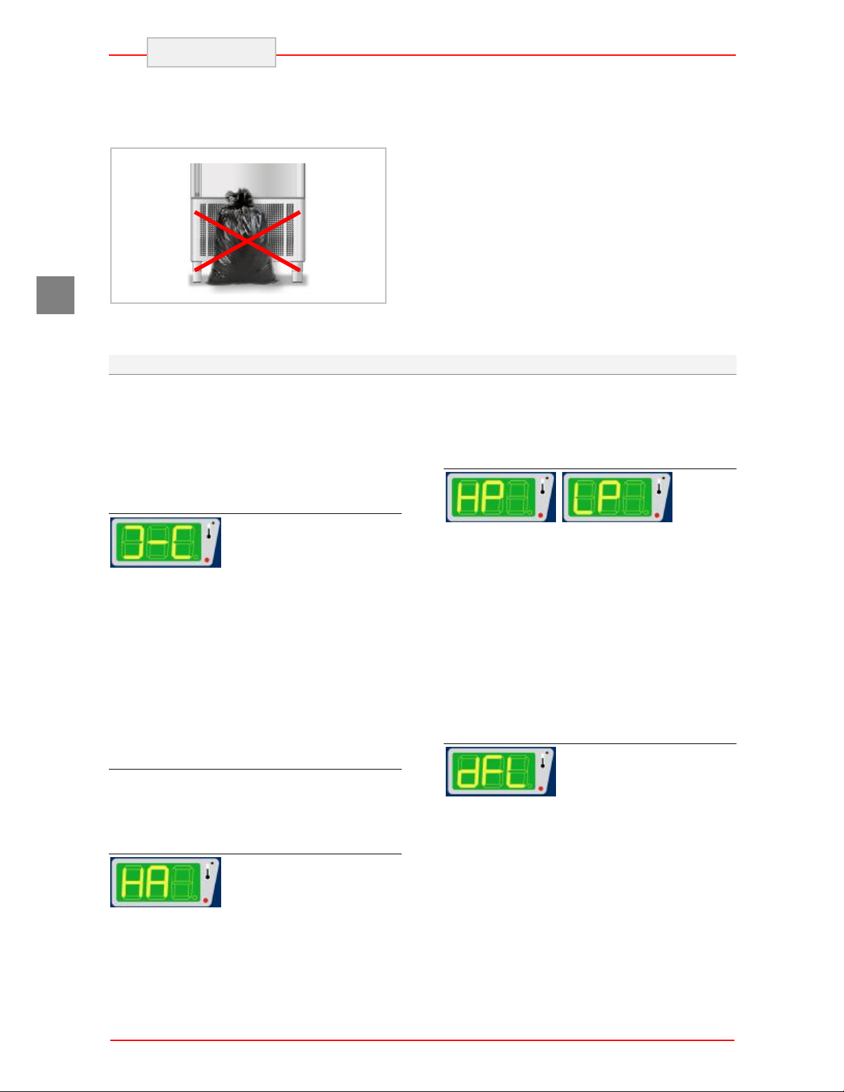
! When using the appliance, never obstruct the
air inlet when the appliance is on, so as not to
compromise its performance and safety.
! Never stretch the power cable.
4.1. Safety Devices
During the running of appliance, some control
devices may activate and govern the correct
running of the machine. In other cases, they may
deactivate parts or the whole machine, to put the
appliance in safe conditions. The main controls
are listed.
Door micro switch
If the door is opened, the
magnetic switch placed on the control board
opens and, during blast-chilling or shock-freezing,
evaporator fans go off and a warning message
appears on the display at the same time. This
condition may also be determined when the door
is not perfectly aligned to or near the control
board: in this case with the machine in the STOP
phase, no cycle may be started.
If a U.V. sterilisation cycle is active, the
functioning of the U.V. lamp is interrupted. The
cycle continues when the door is closed.
Protective Fuses
Some protection fuses in the general power
supply line are activated in case of overload.
Other fuses are prepared for the evaporator fans.
Thermal relay
In the case of faulty operation
that results in exceeding the current absorption
limits of the electric system, the thermal relay will
operate to stop the machine. This intervention is
In order to guarantee hygiene and protect the
foodstuffs from contamination, the elements that
come into direct or indirect contact with the
foodstuffs must be cleaned very well along with
the surrounding areas. These operations must
only be performed using detergents that can be
used with foodstuffs, avoiding inflammable
products or those that contain substances that are
harmful to personal health.
In the case of prolonged inactivity, as well as
disconnecting all the supply lines, it is necessary
to accurately clean all internal and external parts
of the appliance.
shown on the display by means of the wording
“HA”. If the circuit breaker relay has intervened, it
must be restored manually (see specific chapter).
High and low pressure switches
If, due to
environmental conditions or faulty operation, the
minimum/maximum pressure values in the
refrigerating circuit should become excessive, the
maximum/minimum safety pressure switch (in the
5 Pans version, only the maximum safety
pressure switch) will operate to stop the
appliance. The machine can be switched on again
only after the pressure has returned to an
acceptable value. If a high pressure alarm should
occur, the wording “HP” will appear on the
display. The wording “LP” will appear if there is a
low pressure alarm.
Evaporator Fan Micro switch
If the deflector is opened to
inspect the evaporator or fans, this micro switch
positioned on the evaporator deflector,
deactivates machine functioning. Closure of the
deflector with the successive disappearance of
the alarm on the display, restores normal machine
functioning.
6
Page 9

5. USE AND FUNCTIONING
5.1. Description of the Functioning Cycles
The following are brief descriptions and types of
operating cycles.
Temperature Blast Chilling
This cycle allows a reduction in temperature in the
product core from +90°C to +3°C as quickly as
possible and within a MAX time of 90 minutes.
The cycle ends when the value +3°C, read by the
needle probe, is reached.
Time Blast Chilling
This cycle allows a reduction in temperature in the
product core from +90°C to +3°C during the set
time: we remind you that it is advisable to run
some previous testing temperature cycles so to
determine the necessary time for a correct
product blast chilling process. Do not forget that
acquired times and eventually memorised have to
be considered valid for exclusive use of the same
type of product and in the same quantities per
cycle.
Intensive timed blast chilling
For the use of this cycle, the information
contained in the previous paragraph is applicable
concerning the time which can be set and the final
temperature of the product.
The use of this function, which makes it possible
to reduce chilling times, is recommended for foods
with the following characteristics:
Ø Packaged foods or foods in containers
Ø Foods with a thickness greater than 50
mm
Ø Foods with a high fat content
Temperature Shock Freezing
This cycle allows a reduction in temperature in the
product core from +90°C to -18°C as quickly as
possible and within a MAX time of 270 minutes.
The cycle ends when the value -18°C, read by the
needle probe, is reached.
ENGLISH
Time Shock Freezing
This cycle allows a reduction in temperature in the
product core from +90°C to -18°C during the set
time: we remind you that it is advisable to run
some previous automatic test cycles so to
determine the necessary time for a correct
product blast chilling process. Do not forget that
acquired times and eventually memorised have to
be considered valid for exclusive use of the same
type of product and in the same quantities per
cycle.
SOFT Time Shock Freezing
The use of this function is recommended in the
presence of foodstuffs that fear a large initial heat
shock or foodstuffs with different ingredients as
composition (e.g.: fresh pasta) and therefore
require slower and homogeneous shock freezing.
Preservation
At the end of each cycle as described above,
either temperature or time cycle, the preservation
cycle will be started automatically, with no time
limit. The freezer temperature will refer to last
cycle, just concluded:
Ø + 3°C for blast chilling
Ø -25°C for shock-freezing
Warning: use of this cycle is recommended only
for short periods prior to storage of the product in
a storage unit or in case of emergency, so as to
avoid such a limited use of a machine with such
high potential.
Defrosting
The frost forming on the evaporator following the
deposit of humidity from the product can
jeopardise the correct functioning of the
appliance. A defrosting cycle must be carried out
to restore full functionality.
The defrosting cycle ends automatically when the
set temperature is reached.
GB
7
Page 10
ENGLISH
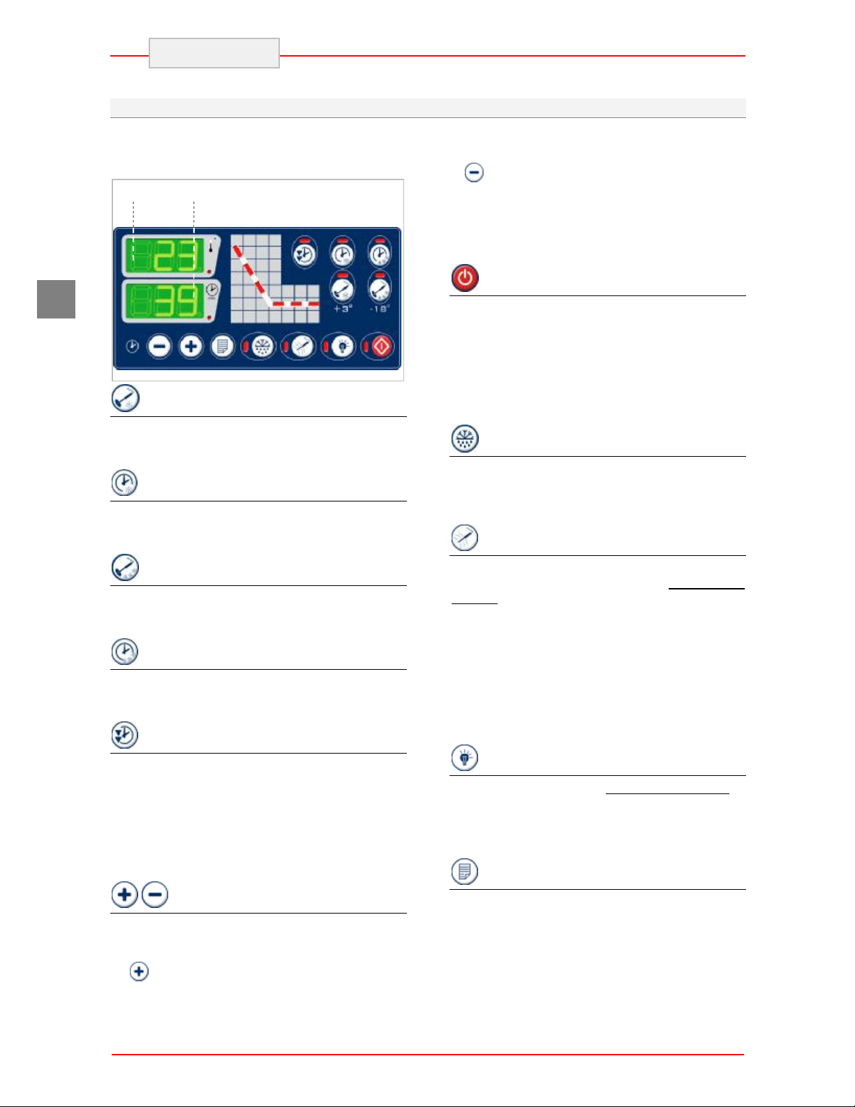
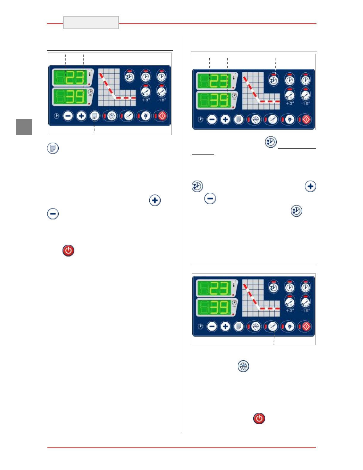
5.2. Description of the Controls
Below is a brief description of the functions carried
out by the keys on the control panel.
DY1
DY2
display of the compartment temperature (display
DY1).
If is pressed during a temperature-regulated
cycle, it makes it possible to pass from the display
of the remaining time to display of the real time
passed from the start of the cycle (display DY2).
Pressing both keys simultaneously makes it
possible to enter parameters programming mode.
GB
Temperature Blast chilling Key
By pressing the key with the machine at a
standstill, it allows to select a temperature blast
chilling cycle (+90°Cà+3°C).
Time Blast chilling Key
By pressing the key with the machine at a
standstill, it allows to select a time blast chilling
cycle.
Time Blast chilling Key
By pressing the key with the machine at a
standstill, it allows to select a temperature shock
freezing cycle (+90°Cà-18°C).
Time Shock freezing Key
By pressing the key with the machine at a
standstill, it allows to select a time shock freezing
cycle.
Intensive Cycle Key
The key is active in the time cycles. If pressed
after a blast chilling cycle has been selected, it
selects the intensive function; if pressed after a
shock freezing cycle has been selected, it selects
the SOFT function.
If pressed for 5 seconds with the machine
stopped, it makes it possible to set the current
time, day and year
.Time increase and decrease keys
When the time blast chilling and/or shock freezing
mode is selected, these buttons allow to set the
cycle duration.
If is pressed during automatic temperatureregulated cycle, it makes it possible to change
from the display of the needle temperature to the
Cycle start key
Once a cycle has been selected, press this button
to start the cycle.
If it is pressed during functioning the appliance
stops; the setting of the previous cycle selected
remains, which can be started immediately.
By pressing this button for at least 5 seconds the
machine passes to the stand-by mode. Repeat
the procedure to reactivate the board.
DEFROST key
When the machine is off a manual defrosting
cycle can be started.
The defrosting cycle ends automatically when the
set temperature is reached.
Heated Probe Key
In appliances in which the needle probe can be
heated, once this key is pressed with the machine
stopped, makes it possible to heat the needle
probe so that it is easier to pull it out of the frozen
product.
If during a chilling / freezing cycle the "needle
probe not inserted" alarm is signalled (see
paragraph on alarms), press the key to silence the
alarm after checking that the needle probe is
properly inserted into the product, then restore
automatic operation.
Germicidal lamp key
With the machine stopped and the door closed, it
makes it possible to switch on an internally
located UV lamp for a set time. This lamp
sterilises the compartment at the beginning and at
the end of the day after it has been cleaned.
Programmes Selection Key
With the machine at a standstill, it makes it
possible to recall and/or memorise 99 timed
chilling or freezing programs.
8
Page 11
L5 L1 L2 1 L4 L1 L2
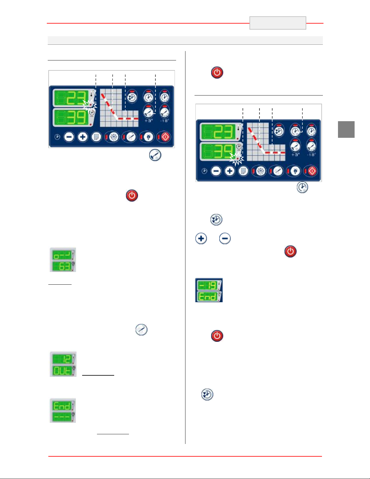
5.3. Functionality
Temperature Blast Chilling (+90 à+3°C)
Select positive chilling by pressing (the
corresponding LED switches on) confirmed by the
lighting of LED L4. The display DY2 shows the
maximum possible time for this cycle: 90 minutes.
Insert the needle probe into the product.
Start the cycle by pressing the key (the
corresponding LED switches on). The start of the
cycle is also confirmed by LED L1 switching on.
During the first minutes of operation, the control
unit checks the exact positioning of the needle
probe.
The appearance on display DY1 of
the “o - -” message accompanied by
an intermittent sound means that the
verification of the correct insertion of
the product probe has given a
negative result and therefore the reading on the
needle probe cannot be considered as valid. The
control unit activates a timed safety cycle (LEDL4
switches off and LED L5switches on).
To silence the alarm and re-activate the automatic
temperature-regulated cycle, re-position the
needle probe and then press (LED L5
switches off and LED L4 switches on).
If the product has not reached 3°C
after 90 minutes the cycle is not
concluded: the buzzer is triggered
intermittently and indicators DY1 and
DY2 indicate the temperature of the
product and “OUt“ respectively.
The blast chilling cycle is concluded
successfully as soon as the
temperature measured by the
product probe reaches 3°C: the
buzzer is triggered intermittently and indicators
DY1 and DY2 indicate “End” and “---“
ENGLISH
respectively. An automatic preservation cycle is
activated (LEDL1 switch off and L2 switch on).
Press to conclude the preservation cycle.
Time Blast Chilling
1
GB
Select positive chilling by pressing (the
corresponding LED switches on) confirmed by the
lighting of LED L5.
If you wish to choose the intensive chilling cycle,
press (the corresponding LED switches on)
Select the required blast chilling time using keys
and .
Start the cycle by pressing the key (the
corresponding LED switches on). The start of the
cycle is also confirmed by LED L1 switching on.
The correct conclusion of the cycle is
signalled by the “End” message on
display DY2 and by an intermittent
noise for a few seconds.
At the end of the set time, the blast chilling cycle
is concluded and a preservation cycle is
automatically started (LED L1 switch off and
LEDL2 switch on).
Press to conclude the preservation cycle.
Notes: the duration of the intensive phase is
calculated automatically by the control unit based
on the set time; the final part of the cycle does
however take place in normal mode to avoid
surface freezing of the product and is confirmed
by the extinguishing of the LED that corresponds
to .
9
Page 12
L5 L1 L2 1 L4 L1 L2
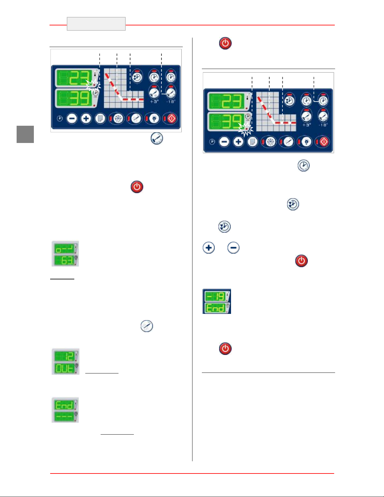
ENGLISH
GB
Temperature Shock Freezing (+90 à-18°C)
Select freezing by pressing (the
corresponding LED switches on) confirmed by the
lighting of LED L4. The display DY2 shows the
maximum possible time for this cycle: 270
minutes.
Insert the needle probe into the product.
Start the cycle by pressing the key (the
corresponding LED switches on). The start of the
cycle is also confirmed by LED L1 switching on.
During the first minutes of operation, the control
unit checks the exact positioning of the needle
probe.
The appearance on display DY1 of
the “o - -” message accompanied by
an intermittent sound means that the
verification of the correct insertion of
the product probe has given a
negative result and therefore the reading on the
needle probe cannot be considered as valid. The
control unit activates a timed safety cycle (LEDL4
switches off and LED L5switches on).
To silence the alarm and re-activate the automatic
temperature-regulated cycle, re-position the
needle probe and then press (LED L5
switches off and LED L4 switches on).
If the product has not reached -18°C
after 270 minutes the cycle is not
concluded: the buzzer is triggered
intermittently and indicators DY1 and
DY2 indicate the temperature of the
product and “OUt“ respectively.
The shock freezing cycle is
concluded successfully as soon as
the temperature measured by the
product probe reaches -18°C: the
buzzer is triggered intermittently and indicators
DY1 and DY2 indicate “End” and “---“
respectively. An automatic preservation cycle is
activated (LEDL1 switch off and L2 switch on).
Press to conclude the preservation cycle.
Time Shock Freezing (+90 à-18°C)
1
Select freezing by pressing (the
corresponding LED switches on) confirmed by the
lighting of LEDL5: in this cycle the intensive
function is activated automatically (the
corresponding LED switches on )
If you wish to choose the SOFT freezing cycle,
press (the corresponding LED switches off)
Select the required shock freezing time using keys
and .
Start the cycle by pressing the key (the
corresponding LED switches on). The start of the
cycle is also confirmed by LED L1 switching on.
The correct conclusion of the cycle is
signalled by the “End” message on
display DY2 and by an intermittent
noise for a few seconds.
At the end of the set time, the shock freezing
cycle is concluded and a preservation cycle is
automatically started (LED L1 switch off and LED
L2 switch on).
Press to conclude the preservation cycle.
HACCP data printer (Optional)
If the printer is enabled, the following events are
printed:
Ø print heading : date, time and selected cycle;
Ø cycle start: compartment and needle
temperature;
Ø alarms : type of alarm, time, compartment
and needle temperature;
Ø cycle end: time, compartment and needle
temperature;
Ø start preservation: time, compartment and
needle temperature;
10
Page 13
************************
DY1 DY2
ENGLISH
Ø Defrost: time, compartment and needle
temperature;
Ø alarms : type of alarm, time, compartment
and needle temperature;
Ø preservation record: time, compartment and
needle temperature every 30 minutes:
The alarms that can be printed are:
DOOR →Door opening
DFL →Evaporator deflector
HP →High pressure
LP →Low pressure
HT →Condenser high T
HA →Compressor circuit breaker switch
AL →Compartment high temperature alarm
(HACCP)
A printing example follows.
-----------************************
Date:24/09/2004
Time:12:28:45
Program:Automatic
CORE Freezing
Start
TIME CHAMBER CORE
0:00 20 62
Alarm:DOOR
0:55 1 11
End
TIME CHAMBER CORE
1:35 -3 3
Holding Cycle
Start
TIME CHAMBER CORE
18:10 -3 4
18:40 3 3
********DEFROSTING*****
18:45 6 3
Alarm: DOOR
18:55 8 3
Programs Memorisation
1
To memorise a work cycle, set it as if it were a
timed program in machine standstill mode.
Press for at least 5 seconds, a beep of the
buzzer confirms the input into programs
memorisation.
Flashing P1 appears on display DY1
corresponding to the first program that can be
memorised; select and the program
number to memorise: display DY2 will show the
message "USE" if the program is already used.
Press again to confirm the memorisation.
Note:
If a program is selected with data that is already
set, this program will be overwritten with the newly
set data.
If more than ten seconds have passed since the
last key pressed, DY1 will once again display the
temperature. Memorisation will be exited and the
program will not be memorised.
GB
11
Page 14
1 1 1
ENGLISH
GB
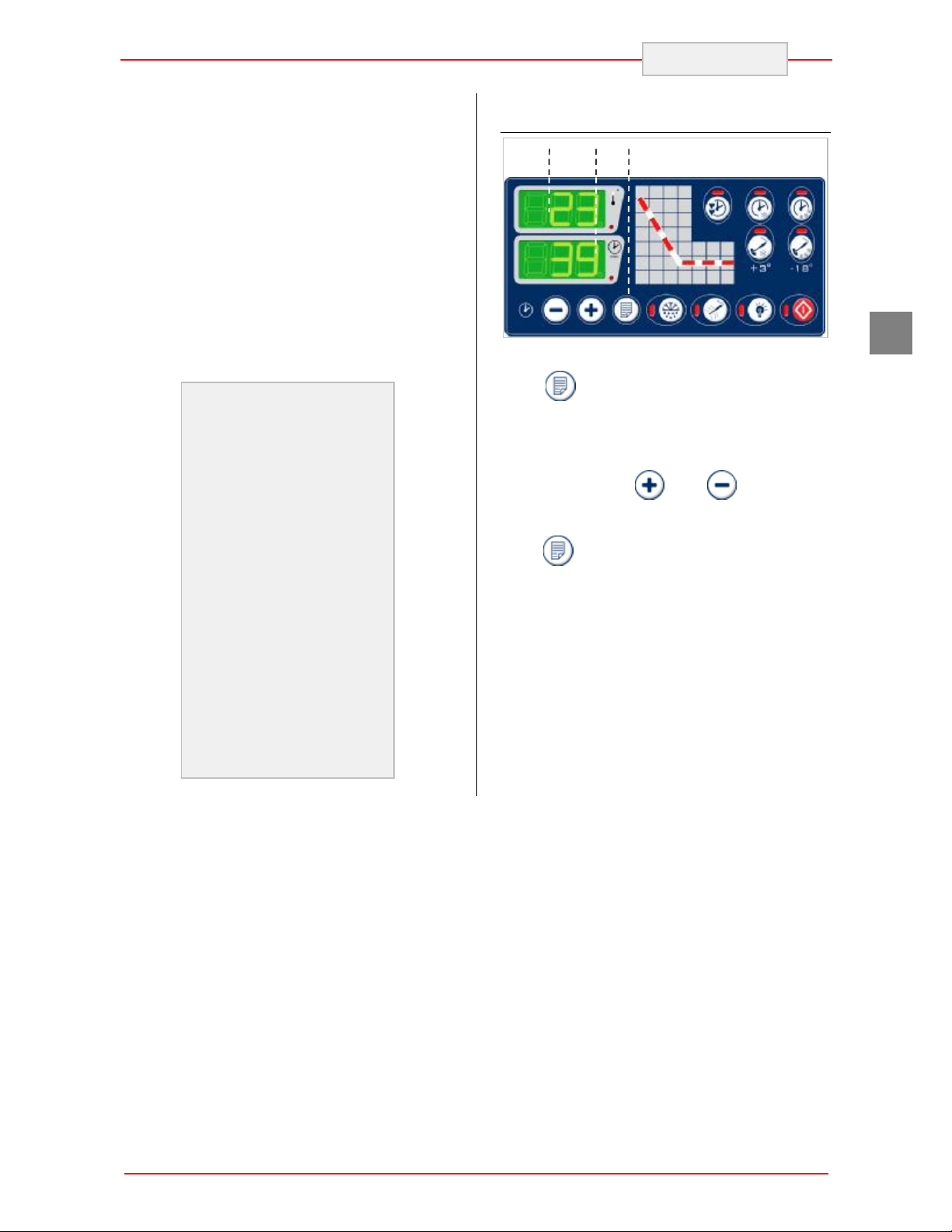
Programs Recall
DY1
With the machine stopped, press and release
(the corresponding LED switches on). The
temperature display shows the code P followed by
the program number, for example P1, while the
time display shows the memorised set time and
the LED indicators that correspond to the selected
operating mode switch on.
Select the required program using keys and
DY2
4.4.3. Setting the time and date
DY1
To access time setting, press for at least five
seconds.
The display DY1 will show Hr (hours), Mn
(minutes), dA (day), Mo (month) and Yr (year),
while display DY2 will display the settings relative
to the abbreviations shown by display DY1. Press
to scroll the various abbreviations, while
and can be used to update the relative
DY2
. If a program is selected that has not been
memorised, “ --- “ appears on the display and the
blast chilling mode LEDs remain off.
Once the required programme has been selected,
press to start the cycle.
If ten seconds pass from the last time a key is
pressed the display DY1 displays the
temperature.
values. Exit timer setting by pressing after
having displayed Yr (year) or due to timeout of 10
seconds.
The new data set for the timer is immediately
active
Defrosting
v Make sure the machine is in STOP mode.
v Press key for defrosting.
The “DEF” message on the display indicates a
defrosting cycle is in progress.
Defrosting is performed by forced ventilation using
the evaporating fans; the cycle may be performed
with the door open or closed and be interrupted at
any time by pressing the key.
12
Page 15
1
ENGLISH
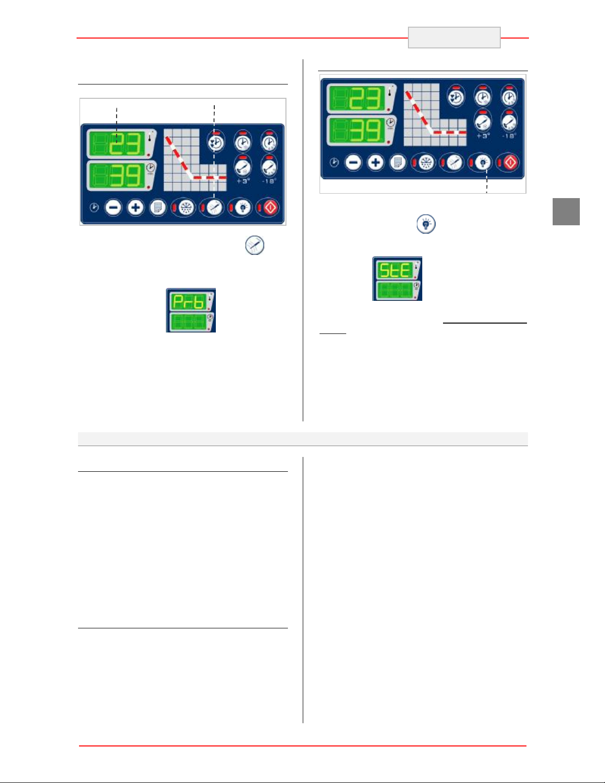
Needle Probe Heating (Optional)
DY1
At the end of a work cycle, press (the
corresponding LED switches on) to activate
needle probe heating, which will make it easier to
extract the probe from the frozen product. Display
DY1 will show ‘Prb’:
This function is not active if:
· the needle probe provided is not a type
which can be heated
· the temperature of the needle probe is
greater than 0°C
The cycle is automatically interrupted at the end of
the envisioned time.
5.4. Recommendations for Use
Prolonged Inactivity
If the appliance remains inactive for a long period,
proceed as follows:
1. Use the automatic isolating switch to
deactivate connection to the main electrical
line.
2. Clean the appliance and surrounding areas
thoroughly;
3. Spread a thin layer of cooking oil onto the
stainless steel surfaces;
4. Carry out all maintenance operations;
5. Leave the doors ajar to prevent the formation
of mould and/or unpleasant odours.
Recommendations for normal use
In order to ensure correct use of the appliance, it
is good practice to apply the following
recommendations:
UV lamp (optional)
1
At the end of the job, after having cleaned the
compartment, press (the relative LED
switches on) compartment sterilization is
activated using the ultra-violet light; display DY1
shows ‘StE’:
This cycle can be started only with the door
closed and it will be interrupted immediately if the
door is opened during sterilization.
For correct machine efficiency and hygiene, it is in
any case advisable to clean the compartment
thoroughly each time you finish using the
machine.
GB
áDo not insert foodstuffs that are well above
the temperature of 65°C. As well as initially
overloading the machine it can make protections
intervene that prolong temperature descent times.
If possible, a brief external period is useful to
lower the temperature to acceptable values.
Check the planarity of the appliance rest surface.
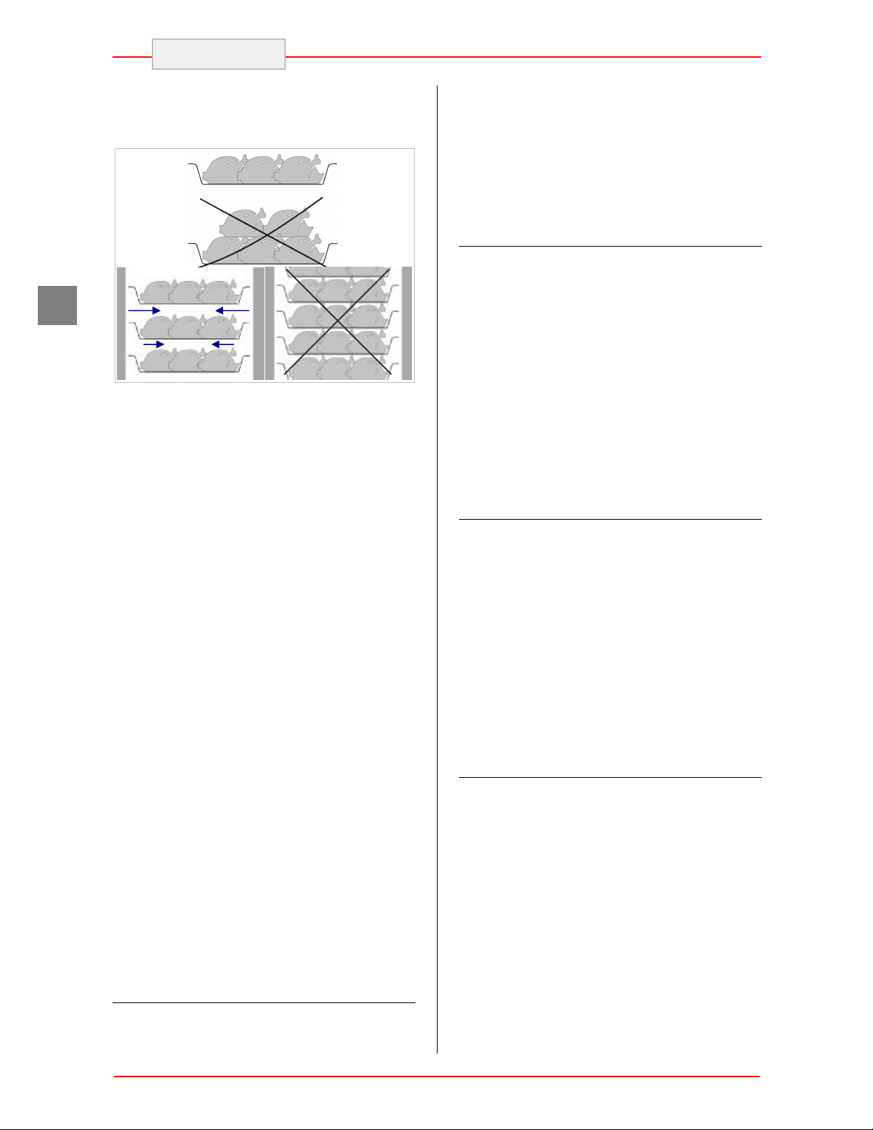
i Do not stack the materials to be preserved
in contact with the internal walls, so blocking the
circulation of air, which guarantees uniformity of
the internal temperature of the refrigerated
compartment.
i There must be a sufficient space between
the basins and trays used in order to guarantee a
sufficient flow of cold air on the entire product.
Therefore avoid the following positions of trays
and/or basins stated below.
! Do not obstruct the zone in front of the
condensing unit in order to favour heat disposal
from the condenser to a maximum.
Always keep the front of the condenser clean.
i Never obstruct the inlet of the evaporator
fans.
13
Page 16
ENGLISH
GB
i Products that are more difficult to chill
because of their composition and size should be
placed in the centre.
Limit the number of times and the duration of time
the doors are opened.
! Blast chilling data refer to standard products
(low fat content) with a thickness below 50 mm;
therefore avoid overlaying products or the
insertion of pieces with a much higher thickness.
This would, in fact, lead to an extension of blast
chilling times. Always distribute the product well
on the trays or basins or in the case of thick
pieces decrease the amount to blast chill.
iAfter blast chilling/shock freezing the
product, it can be stored in a preservation cabinet
after having been duly protected. A tag should be
applied describing the contents of the product,
blast chilling/shock freezing date and expiry date.
When the product has been blast chilled it must
be preserved at a constant temperature of +2°C ,
while if it has been shock frozen it must be
preserved at a constant temperature of -20°C.
i The chiller should be used for storage for
short periods only.
! To prevent bacterial contamination or
contamination of any other biological nature,
the needle probe must be disinfected after
use.
! To extract the product that has undergone blast
chilling or shock freezing, always wear gloves to
protect the hands, as "burns" may occur from the
cold.
i Blast chilling Cycle
With this operating modality the chiller keeps the
temperature of the refrigerating compartment
close to zero during the entire chilling process in
order to ensure a gradual drop in the temperature
of the product to +3°C. In this way, ice crystals do
not form on the surface of the product. This cycle
should be used preferably for products that are
not packed and whose physical/organoleptic
characteristics could be damaged by the
formation of superficial ice (e.g. fish).
i Intensive Blast Chilling Cycle
With this operating mode, at the beginning the
chiller maintains the temperature of the
refrigerating compartment at a much lower than
the value set for normal chilling, in order to
accelerate the drop in temperature of the product.
When the product reaches the fixed temperature
(temperature at which ice could form on the
external surface product) the internal temperature
of the compartment rises to the temperature set
for normal positive chilling. This blast chilling
method should be used preferably for products
that are packed and whose physical/organoleptic
characteristics are not damaged by the formation
of superficial ice.
i Shock freezing Cycle
With this chilling modality the chiller maintains the
temperature value in the compartment below 18°C, which is the end temperature of shock
freezing. For shock freezing to be successful and
fast, food should be in small pieces, especially if it
has a high fat content. The largest pieces should
be placed in central trays. If it takes longer than
standard time to shock freeze and the sizes
cannot be reduced, decrease the quantity and
precool the chiller compartment by starting an
empty shock freezing cycle before shock freezing
the product.
i Shock freezing Cycle SOFT
In this case, the shock freezing cycle is divided in
two phases that differ depending on the
compartment set point used. The first phase
consists in a cycle around the compartment set
point defined for normal blast chilling. The
passage to the second phase starts when the
core-probe reaches a pre-defined temperature
exchange value or when the time elapsed is equal
to a pre-set percentage of the total time. In the
second phase, the compartment reference set
point will be the same as the shock freezing one.
This type of shock freezing allows a more even
freezing of the product, avoiding the external
formation of ice when the core temperature is still
high.
14
Page 17

6. CLEANING AND MAINTENANCE
6.1. Recommendations for Cleaning and Maintenance
particular, deactivate the electrical power supply
! Activate all envisioned safety devices before
carrying out any maintenance interventions. In
6.2. Routine Maintenance
Routine maintenance consists of daily cleaning of
all the parts which can come into contact with
foodstuffs and the periodic maintenance of the
burners, nozzles and draining pipes.
Correct maintenance allows the user to maximise
performance levels and operating life and
constantly maintain safety requirements.
Do not spray the appliance with direct jets of
water or using high pressure appliances.
Do not use iron wool, brushes or scrapers to clean
the stainless steel as ferrous particles could be
deposited which, on oxidising, could lead to rust.
6.3. Extraordinary Maintenance 10T and 14T
iHave the following operations carried out
periodically by specialised staff:
Ø Check the perfect sealing of the door
gaskets and replace them if necessary.
Ø Check that the electric connections have
not loosened.
using the automatic isolating switch.
To remove hardened residues, use wooden or
plastic spatulas or abrasive rubber pads.
During long periods of inactivity, spread a
protective layer on all stainless steel surfaces by
wiping them with a cloth soaked in Vaseline oil
and airing the rooms periodically.
! Do not use products which contain substances
which are harmful and dangerous for personal
health (solvents, petrol etc.).
At the end of the day it is advisable to clean:
Ø the cooling compartment
Ø the appliance.
Ø Check the efficiency of the heating
element resistance
Ø Check functioning of the board and
probes.
Ø Check the efficiency of the electrical
system.
Ø Clean the evaporator.
Ø Clean the condenser.
ENGLISH
GB
15
Page 18

D C C
Cleaning the evaporator
Clean the evaporator periodically.
ENGLISH
Cleaning the condenser
Clean the condenser periodically.
GB
! As the fins of the evaporator are very sharp,
always wear protective gloves for the next
phases.
i Only a brush must be used for cleaning: do
not use jets of liquid or sharp instruments.
To access the evaporator proceed as follows:
1. Open the door (A) of the appliance.
2. Remove the runners (B):
3. Loosen the two screws (C) on the right of the
deflector.
4. Turn the deflector (D) to the left
B
A
! As the fins of the condenser are very sharp,
always wear protective gloves for the next
phases. Use protective masks and glasses in the
presence of dust.
i Whenever the condenser has a deposit of
dust in correspondence with the fins, this can be
removed using a suction device or with a brush
applied, using a vertical movement along the
direction of the fins.
! No other instruments must be used, which may
deform the fins and therefore the efficiency of the
appliance.
To clean, proceed as follows:
1. Open the door (A) of the appliance.
2. Remove the lower panel (B) from the
technical compartment: to do this, remove
the screw fasteners (C).
3. It is now possible to clean the finned part
of the condenser (D) using suitable tools
and protection devices.
4. After cleaning, close the control panel and
fix it with the screws removed beforehand.
A
B
C
D
C
B
16
Page 19

D
E
Fuse replacement and thermal relay rearm
i The fuses (A) and the thermal relay (B) are
in the upper part of the blast chiller. To access
these just open the control panel (C) by loosening
the two screws positioned in the lower part of the
control panel and rotating it upwards. After
opening, make sure that it does not fall back
down.
C
A
B
ENGLISH
B
A
B
GB
C
Rearm the thermal relay
using the grey button
U.V. Lamp Replacement
To access the evaporator proceed as follows:
1. Open the door (A) of the appliance.
2. Remove the runners (B):
3. Loosen the two screws (C) on the front of the
deflector.
4. Turn the deflector (D) to the right.
Once the deflector is turned, it is possible to
switch the UV lamp on. That lamp can be
removed turning it (E). Carry out all the operations
in reverse order after having removed the U lamp.
6.4. Extraordinary Maintenance 10TR
iHave the following operations carried out
periodically by specialised staff:
Ø Check the perfect sealing of the door
gaskets and replace them if necessary.
Ø Check that the electric connections have
not loosened.
Ø Check the efficiency of the heating
element resistance
Ø Check functioning of the board and
probes.
Ø Check the efficiency of the electrical
system.
Ø Clean the evaporator.
Ø Clean the condenser.
17
Page 20

B D C C
A
C
Cleaning the evaporator
Clean the evaporator periodically.
ENGLISH
Cleaning the condenser
Clean the condenser periodically.
GB
! As the fins of the evaporator are very sharp,
always wear protective gloves for the next
phases.
i Only a brush must be used for cleaning: do
not use jets of liquid or sharp instruments.
To access the evaporator proceed as follows:
1. Open the door (A) of the appliance.
2. Remove the runners (B):
3. Loosen the two screws (C) on the front of the
deflector.
4. Turn the deflector (D) to the left
B
A
! As the fins of the condenser are very sharp,
always wear protective gloves for the next
phases. Use protective masks and glasses in the
presence of dust.
iWhenever the condenser has a deposit of
dust in correspondence with the fins, this can be
removed using a suction device or with a brush
applied, using a vertical movement along the
direction of the fins.
! No other instruments must be used, which may
deform the fins and therefore the efficiency of the
appliance.
To clean, proceed as follows:
1. Open the door (A) of the appliance.
2. Remove the lower panel (B) from the
technical compartment: to do this, remove the
screw fasteners (C).
3. It is now possible to clean the finned part of
the condenser (D) using suitable tools and
protection devices.
4. After cleaning, close the control panel and fix
it with the screws removed beforehand.
C
D
B
D
18
Page 21

C
Fuse replacement and thermal relay rearm
i The fuses (A) and the thermal relay (B) are
in the upper part of the blast chiller. To access
these just open the control panel (C) by loosening
the two screws positioned in the lower part of the
control panel and rotating it upwards. After
opening, make sure that it does not fall back
down.
ENGLISH
B
A
C
A
B
Rearm the thermal relay
using the grey button
U.V. Lamp Replacement
To access the evaporator proceed as follows:
1. Open the door (A) of the appliance.
2. Remove the runners (B):
3. Loosen the screws (C) on the front of the
deflector.
4. Turn the deflector (D) to the right.
Once the deflector is turned, it is possible to
switch the UV lamp on. That lamp can be
removed turning it (E). Carry out all the operations
in reverse order after having removed the U lamp.
6.5. Extraordinary Maintenance 6T 2/1
iHave the following operations carried out
periodically by specialised staff:
Ø Check the perfect sealing of the door
gaskets and replace them if necessary.
Ø Check that the electric connections have
not loosened.
Ø Check the efficiency of the heating
element resistance
GB
D
E
D
Ø Check functioning of the board and
probes.
Ø Check the efficiency of the electrical
system.
Ø Clean the evaporator.
Ø Clean the condenser.
19
Page 22

D B
A
B
C
D
Cleaning the evaporator
Clean the evaporator periodically.
ENGLISH
Cleaning the condenser
Clean the condenser periodically.
GB
! As the fins of the evaporator are very sharp,
always wear protective gloves for the next
phases.
Only a brush must be used for cleaning: do not
use jets of liquid or sharp instruments.
To access the evaporator proceed as follows:
1. Open the door (A) of the appliance.
2. Remove the runners (B):
3. Loosen the two screws (C) on the front of the
deflector.
4. Turn the deflector (D) to the right.
A
! As the fins of the condenser are very sharp,
always wear protective gloves for the next
phases. Use protective masks and glasses in the
presence of dust.
iWhenever the condenser has a deposit of
dust in correspondence with the fins, this can be
removed using a suction device or with a brush
applied, using a vertical movement along the
direction of the fins.
! No other instruments must be used, which may
deform the fins and therefore the efficiency of the
appliance.
To clean, proceed as follows:
1. Open the door (A) of the appliance.
2. Remove the lower panel (B) from the
technical compartment: to do this, remove the
screw fasteners (C).
3. It is now possible to clean the finned part of
the condenser (D) using suitable tools and
protection devices.
4. After cleaning, close the control panel and fix
it with the screws removed beforehand.
C
C
C
C
20
Page 23

A
ENGLISH
Fuse replacement and thermal relay rearm
i The fuses (E) and the thermal relay (F) are
in the lower part of the blast chiller. To access this
remove the lower control panel using the same
method listed for the access and cleaning of the
condenser.
E F
U.V. Lamp Replacement
To access the evaporator proceed as follows:
1. Open the door (A) of the appliance.
2. Remove the runners (B):
3. Loosen the two screws (C) on the front of the
deflector.
4. Turn the deflector (D) to the right.
Once the deflector is turned, it is possible to
switch the UV lamp on. This lamp can be
removed by sliding it upwards (E). Carry out all
the operations in reverse order after having
removed the U lamp.
B
GB
Rearm the thermal relay
using the grey button
6.6. Extraordinary Maintenance 10T 2/1
iHave the following operations carried out
periodically by specialised staff:
Ø Check the perfect sealing of the door
gaskets and replace them if necessary.
Ø Check that the electric connections have
not loosened.
Ø Check the efficiency of the heating
element resistance
E
D
C
Ø Check functioning of the board and
probes.
Ø Check the efficiency of the electrical
system.
Ø Clean the evaporator.
Ø Clean the condenser.
21
Page 24

A
A B
C
C D B
ENGLISH
GB
Cleaning the evaporator
Clean the evaporator periodically.
! As the fins of the evaporator are very sharp,
always wear protective gloves for the next
phases.
i Only a brush must be used for cleaning: do
not use jets of liquid or sharp instruments.
To access the evaporator proceed as follows:
1. Open the door (A) of the appliance.
2. Remove the runners (B):
3. Loosen the two screws (C) on the right of the
deflector.
4. Turn the deflector (D) to the right.
B
Cleaning the condenser
Clean the condenser periodically.
! As the fins of the condenser are very sharp,
always wear protective gloves for the next
phases. Use protective masks and glasses in the
presence of dust.
iWhenever the condenser has a deposit of
dust in correspondence with the fins, this can be
removed using a suction device or with a brush
applied, using a vertical movement along the
direction of the fins.
! No other instruments must be used, which may
deform the fins and therefore the efficiency of the
appliance.
To clean, proceed as follows:
1. Open the door (A) of the appliance.
2. Remove the lower panel (B) from the
technical compartment: to do this, remove the
screw fasteners (C).
3. It is now possible to clean the finned part of
the condenser (D) using suitable tools and
protection devices.
4. After cleaning, close the control panel and fix
it with the screws removed beforehand.
C
D
C
22
Page 25

C
B A
D A
ENGLISH
Fuse replacement and thermal relay rearm
i The fuses (A) and the thermal relay (B) are
in the upper part of the blast chiller. To access
these just open the control panel (C) by loosening
the two screws (D) positioned in the lower part of
the control panel and rotating it upwards. After
opening, make sure that it does not fall back
down.
C
B
U.V. Lamp Replacement
To access the evaporator proceed as follows:
1. Open the door (A) of the appliance.
2. Remove the runners (B):
3. Loosen the two screws (C) on the front of the
deflector.
4. Turn the deflector (D) to the right.
Once the deflector is turned, it is possible to
switch the UV lamp on. That lamp can be
removed turning it (E). Carry out all the operations
in reverse order after having removed the U lamp.
GB
Rearm the thermal relay
using the grey button
E
D
23
Page 26

GB
ENGLISH
7. TROUBLESHOOTING
The information shown below aims to help with
the identification and correction of any anomalies
and malfunctions which could occur during use.
Some of these problems can be resolved by the
Problem Causes Solutions
No voltage
The refrigerator unit does not start
user. For the others, precise skill is required and
they must therefore only be carried out by
qualified staff.
Check the power supply cable.
Check fuses.
Check the correct connection of the
appliance.
The refrigerator unit functions
continuously, cooling insufficiently
The refrigerator unit does not stop
Presence of ice inside the
evaporator
Appliance noise Persistent vibrations
Other causes
Room too hot Air the environment
Dirty condenser clean the condenser
Insufficient door sealing check the gaskets
Insufficient quantity of
refrigerant gas
Condenser fan at a standstill
Probe faulty
Circuit board fault
@ If the problem persists,
contact the after-sales centre.
@ Contact the after-sales
centre.
@ Contact the after-sales
centre.
@ Contact the after-sales
centre.
@ Contact the after-sales
centre.
Carry out a defrosting cycle possibly
with the door open.
@ If the problem persists,
contact the after-sales centre.
check there is no contact between
the appliance and other objects
inside or outside
24
Page 27

7.1. Faults Display
Problem Causes Solutions
"E0" flashes on the display and
the buzzer emits an intermittent
noise
(compartment probe error)
"E1" flashes on the display and
the buzzer emits an intermittent
noise
(evaporator probe error)
"E3" flashes on the display and
the buzzer emits an intermittent
noise
(needle probe error)
Ø The type of probe is
incorrect.
Ø The probe is faulty.
Ø The probe – circuit board
connection is incorrect.
Ø The temperature detected
by the probe is out of the
limits accepted by the
compartment probe in use
ENGLISH
@ Contact the after-sales
centre.
Ø Check that the compartment
probe is the PTC type.
Ø Check the integrity of the
compartment probe.
Ø Check correctness of the
instrument - probe connection.
Ø Check that the temperature in
proximity of the compartment
probe is not out of the accepted
limits
GB
"dFL" flashes on the display and
the buzzer emits an intermittent
noise
"LP" flashes on the display and
the buzzer emits an intermittent
noise
(low evaporation temperature
alarm)
"HP" flashes on the display and
the buzzer emits an intermittent
noise
(high condensation
temperature alarm)
"HA" flashes on the display and
the buzzer emits an intermittent
noise
(compressor circuit breaker
alarm)
The evaporator fan deflector
has been opened.
The pressure detected by the
minimum pressure gauge is
lower than the limit value.
The pressure detected by the
maximum pressure switch is
higher than the limit value.
The absorption of the
compressor has exceeded the
envisioned maximum limit.
@ Contact the after-sales
centre.
Close the evaporator fan deflector.
@ Contact the after-sales
centre.
Ø Check there are no gas leaks in
the plant
Ø Check that the solenoid block
valve opens during compressor
functioning.
@ Contact the after-sales
centre.
Ø Air the environment.
Ø Clean the condenser
Ø Check that the fans function
correctly.
@ Contact the after-sales
centre.
Ø Air the environment.
Ø Clean the condenser
Ø Check that the fans function
correctly.
8. INSTALLATION
8.1. Packaging And Unpacking
Handle and install the appliance respecting the
information provided by the manufacturer, shown
directly on the packaging, on the appliance and in
this manual.
The lifting and transportation system of the
packaged product envisions the use of a fork-lift
truck or a pallet stacker. When using these,
25
Page 28

FRAGILE
DO NOT EXPOSE
ENGLISH
GB
particular attention must be paid to balancing the
weight in order to prevent the risk of overturning
(avoid excessive tilting!).
! ATTENTION: When inserting the lifting device,
pay attention to the power supply cable and the
position of the feet.
The packaging is made of cardboard and the
pallet of wood. A series of symbols is printed on
the cardboard packaging which highlights, in
accordance with international standards, the
provisions to which the appliances are subjected
during loading, unloading, transport and storage.
TOP
HANDLE
WITH CARE
8.2. Installation
All the installation phases must be considered,
from the moment of creation of the general plan.
The installation area must be equipped with all
power supply and production residue drainage
connections and must be suitably lit and respect
current laws regarding hygiene and sanitary
requirements.
TO HUMIDITY
On delivery, check that the packaging is intact and
has not undergone any damage during
transportation.
The transportation company must be notified of
any damage immediately.
The appliance must be unpacked as soon as
possible to check that it is intact and undamaged.
Do not cut the cardboard with sharp tools so as
not to damage to the steel panels underneath.
Pull the cardboard packaging upwards.
After having unpacked the appliance, check that
the features correspond to those requested in the
order;
Contact the dealer immediately if there are any
anomalies.
! Packaging elements (nylon bags, polystyrene
foam, staples …) must not be left within reach of
children.
Remove the protective PVC film from the internal
and external walls, avoiding the use of metal
tools.
i Connect and leave for a certain period of
time (at least 2 hours) before checking
functioning. During transport it is probable that the
compressor lubricant oil has entered the
refrigerant circuit blocking the capillary: as a
consequence the appliance will function for a
certain period of time without producing cold until
the oil has returned to the compressor.
iThe performance of the appliance is
guaranteed with a room temperature of 32°C. A
higher temperature can compromise its
performance and, in more serious cases, cause
the appliance’s protections to start up.
Therefore, consider the most critical room
conditions that can be reached in that position
before making a choice.
Level the appliance by acting on the individual
feet.
! This appliance can only be installed and
operate in rooms which are permanently
ventilated, in order to guarantee correct operation.
! ATTENTION: the appliance requires the
minimum functioning spaces, as shown in the
attachments.
The defrosting water and the water that forms at
the bottom of the refrigerating compartment
during operation or during periodical internal
cleaning must be drained through a prearranged
hose with a minimum diameter 3/4” connected to
the hose at the bottom of the chiller.
A drain trap should also be guaranteed. The drain
must be in compliance with Standards in force.
26
Page 29

8.3. Electric Power Supply Connection
Connection must be carried out by authorised and
qualified staff, respecting the current laws
regarding the subject and using appropriate
prescribed material.
i Before connecting the appliance to the
electric mains, check that the voltage and the
frequency correspond to the data stated on the
registration plate applied on the rear of the
appliance.
iThe appliance is supplied with an operating
voltage of 400V 3+N~ 50Hz. On request, it is
8.4. Condensing unit water connection
The chiller cabinets with water condensation have
been designed to use normal tap water.
Connect the mains pipe to the appliance
connection pipe, positioning a shut-off cock (A) to
interrupt the water supply when necessary. Install
some easily reachable filters downstream from
this.
i The water pressure must be between
150÷300 kPA (1.5÷3 bar).
ENGLISH
possible to have appliances with different
voltages.
! Before connection, ensure the presence of a
relevant differential switch with adequate power in
the mains power supply, upstream from the
appliance, in order to protect the appliance from
overloads or short circuits
!
NON ACCENDERE LA
MACCHINA FINO A CHE
NON E' COLLEGATA
L'ALIMENTAZIONE
IDRICA
DO NOT TUR THE
MACHINE UNLESS IT IS
CONNECTED TO THE
WATER SUPPLY
INGRESSO ACQUAUSCITA ACQUA
WATER INLETWATER OUTLET
GB
! Attachment to the water network must be
carried out before switching the appliance on: if
cooling is missing from the condensing circuit, the
maximum pressure switch intervenes, which
blocks the machine. The machine must also be
checked for leaks that could interfere with
electrical parts and cause short-circuits.
It is preferable for both the water drain and supply
pipes to be fitted with cocks to stop the water
supply to the machine during maintenance.
Both water inlet and drain pipe connections are
3/4”. To know which attachment to use (both 3/4”),
simply follow the indications in the figure (the
same label should be found near the water supply
connections).
i If the water has a high mineral salt content
(i.e. if it is too hard), to ensure long and efficient
life to the exchanger we suggest you install a
water softener at the water inlet.
27
Page 30

Remote condensing unit
Inclination towards the
Blast chiller
ENGLISH
GB
Even if the pressure valve has been calibrated
before leaving the factory, after having connected
the machine to the water supply and turned on the
any cocks installed, check for water leaks from the
8.5. Remote condensing unit
! When installing a remote condensing unit, the
same precautions must be taken as for the
installation of the machine with an integrated
condensing unit. In particular, it is important to
respect the electric installation rules, the fireprevention rules and to keep in mind that under
certain circumstances coolant gas may be
released into the environment (it must be possible
to air the room).
i Performance is guaranteed for remote unit
installations up to a distance of 10 m and with an
insulated intake line (insulation must be at least
13 mm thick).
The recommended pipes are given in the
attachments.
drain when the machine is at a standstill. In case
of a leak, adjust the pressure valve until the leak
stops.
i Both the condensing unit and the coolant
circuit are under pressure using nitrogen therefore
the seal of the circuits can be checked when
turning on the cocks.
After having connected the delivery and intake
pipes and having created a vacuum and then
loaded the pipes, make sure that the welded parts
are hermetically sealed and that there are no
leaks.
The gas load must be checked through the gas
conduit indicator located on the condensing unit.
For installations on the same level or different
level follow the indications in the figure.
In particular, if the remote unit is installed higher,
a siphon is created at every departure/arrival or
re-ascent, while if the unit is installed lower no
siphon is necessary.
taps
taps.
> 0.7 mt
~ 2 mt
compressor 2-3%
> 0.7 mt
2 .. 3%
28
Page 31

ENGLISH
If the remote unit is installed at a lower level than
the chiller, siphons are unnecessary. The
manufacturer guarantees an IP21 rated
protection.
If greater protections are required, the installer
must consider the use of additional guards that do
8.6. Inspection
The appliance is delivered in conditions such that
it can be started-up by the user.
This functionality is guaranteed by passing the
tests (electric inspection - functional inspection,
appearance inspection) and relative certification
through the specific attachments.
At least the following should be checked after
installation:
Ø Check the electric connections.
not limit the exchanging capacity of the
condenser. The connection between the electric
box on the lower compartment of the blast chiller
and the one inside the cabling box must be
present on the remote unit.
GB
Ø Check the functionality and efficiency of
drains.
Ø Check that there are no tools or materials
left in the appliance that could jeopardise
its functionality or even damage the
machine.
Ø Have the appliance perform at least one
complete chill blasting/shock freezing
cycle
29
Page 32

GB
ENGLISH
9. DISPOSAL OF THE APPLIANCE
iThis appliance is marked in compliance with
the 2002/96/EC European Directive, WASTE
ELECTRICAL AND ELECTRONIC EQUIPMENT
(WEEE).
! By assuring that this product is disposed of
correctly, the user contributes to preventing the
potential negative consequences on the
environment and health.
indicates that this product must not be treated as
domestic waste but must be taken to suitable
collection points for the recycling of electric and
electronic appliances.
Dispose of it following local regulations regarding
waste disposal.
For further information regarding the treatment,
recovery and recycling of this product, contact the
relevant local office, the domestic waste collection
service or the shop where the product was
purchased.
The symbol found on the
product or on the accompanying documentation
10. REFRIGERANT TECHNICAL CARD
The refrigerant used in the machine is R404a
fluid. Below find the components of the fluid:
PENTAFLUOROETHANE (HFC R125)
44%
ETHANE 1,1,1 – TRIFLUORO (HFC R143A)
52%
ETHANE 1,1,1,2 TETRAFLUORO (HFC
R134A) 4%
IDENTIFICATION OF DANGERS
The rapid evaporation of the liquid can cause
freezing. The inhalation of high concentrations
of vapour can cause irregular heartbeat, short term
narcotic effects (including vertigo, headache and
mental confusion), fainting and death.
· Effects to the eyes: Freezing or cold burns
caused by contact with the liquid.
· Effects on the skin: Freezing or cold burns
caused by contact with the liquid.
· Effects of ingestion. Ingestion is not
considered a means of exposure
FIRST AID
Eyes: In the case of contact, wash the eye well
using a large amount of water for at least 15
minutes. Consult a doctor.
Effects on the skin: Wash with water for at least 15
minutes after excessive contact. If necessary, cure
freezing by gently warming the area in question.
Consult a doctor in the case of irritation.
Ingestion: Ingestion is not considered a means of
exposure.
Inhalation: If large concentrations are inhaled, go
into the open air. Keep the person calm. If the
person cannot breath, perform artificial respiration. If
respiration is difficult, apply oxygen. Consult a
doctor.
30
Page 33

ALLEGATI
ANNEXES
ANLAGEN
ANNEXEX
ANEXOS
I
Page 34

SCHEDA ALLACCIAMENTI
- CONNECTION CARD
–
ANSCHLUSSSCHEMA
ß
~
10 T
235
870
FICHE DES RACCORDEMENTS- FICHA DE ENLACES
825
41560
110
1645
1800
800
1780
695
Scarico acqua
Water Drain
155
45 45710
70130 625
68 68664
Allacciamento Elettrico400V
Electric Connection3+N ~
135
1585
ß
Vidage Eau
Wasserabfluss
Evacuacion Agua
Branchement Electrique50 Hz
~
Elektroanschluss
Conexiòn elètrica
II
Page 35

SCHEDA ALLACCIAMENTI
- CONNECTION CARD
–
ANSCHLUSSSCHEMA
~
6
T 2/1
14 T
235
1095
FICHE DES RACCORDEMENTS- FICHA DE ENLACES
825
41560
110
1870
2025
800
2005
Scarico acqua
Water Drain
Vidage Eau
ß
Wasserabfluss
Evacuacion Agua
695
ß
155
70130 625
45 45710
68 68664
Allacciamento Elettrico400V
Electric Connection3+N ~
Branchement Electrique50 Hz
~
Elektroanschluss
Conexiòn elètrica
135
1585
III
Page 36

SCHEDA ALLACCIAMENTI
- CONNECTION CARD
–
ANSCHLUSSSCHEMA
ß
~
1800
1645
10TR
800
FICHE DES RACCORDEMENTS- FICHA DE ENLACES
900
60
110
165
1010
1780
470
235
870
695
155
45 45
55
71
900
664
50
60
710
664 6868
220
435
135
700 13070
Scarico acqua
Water Drain
Vidage Eau
ß
Wasserabfluss
1660
Evacuacion Agua
Allacciamento Elettrico400V
15
Electric Connection3+N ~
Branchement Electrique50 Hz
~
Elektroanschluss
Conexiòn elètrica
IV
Page 37

6T
SCHEDA ALLACCIAMENTI
- CONNECTION CARD
–
ANSCHLUSSSCHEMA
ß
~
2/1
73
485
640
130 70825
1080
FICHE DES RACCORDEMENTS- FICHA DE ENLACES
10501025 55
1098
1198
100
45 45960
70 70910
644
55
135
ß
Scarico acqua
Water Drain
Vidage Eau
Wasserabfluss
60
1080
855
50
60
Allacciamento Elettrico400V
Electric Connection3+N ~
Branchement Electrique50 Hz
~
Elektroanschluss
1820
Evacuacion Agua
Conexiòn elètrica
V
Page 38

10T
SCHEDA ALLACCIAMENTI
- CONNECTION CARD
–
ANSCHLUSSSCHEMA
~
165
940
795
2/1
FICHE DES RACCORDEMENTS- FICHA DE ENLACES
1050
110
1745
1900
1880
Scarico acqua
Water Drain
Vidage Eau
ß
Wasserabfluss
Evacuacion Agua
ß
155
120160 800
45 45960
70 70910
50
65
855
50
60
Allacciamento Elettrico400V
Electric Connection3+N ~
Branchement Electrique50 Hz
~
Elektroanschluss
Conexiòn elètrica
135
664
1840
VI
Page 39

10T 14T
10TR 6T 2/1
SCHE
DA ALLACCIAMENTI
- CONNECTION CARD
–
ANSCHLUSSSCHEMA
A B C D B C
FICHE DES RACCORDEMENTS- FICHA DE ENLACES
A
B (ø 16)
C (ø 10)
D
Scatola elettrica
Unità
condensante
remota
Linea
Aspirazione
Linea Liquido
Scatola di
derivazione
Abbattitore
SBRINAMENTO
Ventilazione
Forzata
Remote Unit
Condensing
Terminal Board
Suction Line
Pipe
Discharge Line
Pipe
Control Unit
Terminal Board
DEFROSTING
TYPE
Forced
Ventilation
Bernier unitè
de
condensation
à distance
Ligne
d'aspiration
Ligne de
dèpart
Borner
compartiment
technique
DÉGIVRAGE ABTAUART
Air
Forcè
Klemmenleiste
Installierte
Kühleinheit
Ansaugrohre
Druckrohre Línea de impulsión
Klemmenleiste
Bedienung
Zwangslüftung
Z
fem
Caja eléctrica de
la unidad
condensante
remota
Línea de
Aspiración
Caja de
distribución del
Abatidor
DESCONGELACIÓN
Ventilación
Forzada
VII
Page 40

SCHEDA ALLACCIAMENTI
- CONNECTION CARD
–
ANSCHLUSSSCHEMA
A B C
D E
10T 2/1
FICHE DES RACCORDEMENTS- FICHA DE ENLACES
A
B (ø 22)
C (ø 12)
E (ø 16)
D
Scatola elettrica
Unità
condensante
remota
Linea
Aspirazione
Linea Liquido
Linea Gas Caldo
Scatola di
derivazione
Abbattitore
SBRINAMENTO
Gas Caldo Hot Gas Gaz Chaud
Remote Unit
Condensing
Terminal Board
Suction Line
Pipe
Discharge Line
Pipe
Hot Gas
Line Pipe
Control Unit
Terminal Board
DEFROSTING
TYPE
Bernier unitè
condensation
à distance
Ligne
d'aspiration
Ligne de
dèpart
Ligne de
Gaz Chaud
Borner
compartiment
technique
DÉGIVRAGE ABTAUART
de
Klemmenleiste
fem
Installierte
Kühleinheit
Ansaugrohre
Druckrohre Línea de impulsión
Warmgas
Klemmenleiste
Bedienung
Warmgas
Caja eléctrica de
la unidad
condensante
remota
Línea de
Aspiración
Línea del Gas
Caliente
Caja de
distribución del
Abatidor
DESCONGELACIÓN
Gas Caliente
VIII
Page 41

SCHEDA ALLACCIAMENTI
- CONNECTION CARD
–
ANSCHLUSSSCHEMA
10T 14T
FICHE DES RACCORDEMENTS- FICHA DE ENLACES
IX
Page 42

SCHEDA ALLACCIAMENTI
- CONNECTION CARD
–
ANSCHLUSSSCHEMA
6T 2/1 10T 2/1
FICHE DES RACCORDEMENTS- FICHA DE ENLACES
X
Page 43

Temperatura di funzionamento -
ouvertes
condensa
[°C]
[°C]
10T+
10T
I
T
G
B
F
R
DescrizioneDescriptionDescription
•
min/max
á
Produttività per ciclo - kgProductivity per Cycle - kg.Productivité par cycle - kg.
q
Ciclo Positivo (+90° +3°)Positive Cycle (+90° +3°)Positive Cycle (+90° +3°)
Ciclo Negativo (+90° -18°)Negative Cycle (+90° -18°)Negative Cycle (+90° -18°)
Dimensioni EsterneExternal DimensionDimensions Externes
LarghezzaWidthLargeur
Profondità / con porta apertaDepth / with open doors
AltezzaHeightHauteur
Dimensioni InterneInternal DimensionDimensions Internes
LarghezzaWidthLargeur
ProfonditàDepthProfondeur
AltezzaHeightHauteur
Incernieramento PortaDoor hingesCharnières de porte
Numero e tipo di porteN° and type of doorsNombre et type de portes
Tipo di griglieTrays typeType de plateaux
Capacita di carico - Teglie
H=65 mm
SbrinamentoDefrostDégivrages
ß
Operating Temperature
Max Load Capacity - Trays
H=65 - N°
Température de
fonctionnement - min/max °C -
Profondeur / avec portes
Capacité de chargement plateaux h 65 mm
1/1
+3°C+3°C -18°C
4040
---- 25
800800
825/1585825/1585
18001800
664664
415415
870870
Right SideRight Side
1, Full1, Full
GN 1/1,
600x400
1010
1/1
GN 1/1,
600x400
Tipo di sbrinamentoType of defrostTipe de dégivrages
Evaporazione acqua di
CompressoreCompressor powerPuissance du compresseur
Temperatura di evaporazione -
Potenza - HPPower HPPuissance - HP
Potenza Frigorifera - [watt]Refrigerant Power [watt]Puissance frigorifique - [watt]
RefrigeranteRefrigerantRéfrigérant
Fluido RefrigeranteTypeFluide réfrigérant
Quantita di refrigerante - [gr]Refrigerant quantity [gr]Quantité de réfrigérant - [gr]
Potenza assorbita [watt]Total Power [watt]Puissance [watt]
~
Tensione di AlimentazioneSupply VoltageTension d'alimentation
Potenza Sonora - dBANoise Level - dbANiveau sonore - dBA
U
=
Peso netto - [kg]Net weight [kg]Poids net - [kg]
l
= Di Serie ¨=Opzionalel= Standard ¨=Option
Evaporation of defrost waterÉvaporation condensats
T° Evaporation [°C]
Température d'évaporation -
l
= De Sèrie ¨=Option
XI
Hot GasHot Gas
ManualManual
-10-25
-1,8
44202080
R404aR404a
15001800
23002500
400V/ 50Hz
3+N
6868
400V/ 50Hz
3+N
Page 44

abierta
aberta
Ensambladura con bisagras de
la Puerta
condensación
condensado
(C°)
(C°)
(gr)
10T+
10T
D
E
ModelleDescripciónDescrição
•
Temperaturbereich
min/max °C
á
ProduktivitätProductividad por ciclo – kgProdutividade por ciclo – kg
q
Positiver Zyklus (+90° +3°)Ciclo Positivo (+90° +3°)Ciclo Positivo (+90° +3°)
Negativer Zyklus (+90° -18°)Ciclo Negativo (+90° -18°)Ciclo Negativo (+90° -18°)
Außenabmessungen - mmDimensiones ExterioresDimensões Exteriores
BreiteAnchoLargura
Tiefe/mit geöffneter Tür
HöheAltoAltura
AbmessungenDimensiones InterioresDimensões Interiores
BreiteAnchoLargura
TiefeProfundidadProfundidade
HöheAltoAltura
Türanschlag
Anzahl und Art der TürenNúmero y tipo de puertasNúmero e tipo de portas
EinschubgrößeTipo de rejillasTipo de tabuleiros
Max. Bestückungskapazität
-Höhe der Schalen: 65 mm
AbtauDescongelaciónDescongelação
ß
E
S
Temperatura de
funcionamiento – mín./máx.
Profundidad / con puerta
Capacidad de carga – Fuentes
de 65 mm de alto
Temperatura de
funcionamiento – mín./máx.
Profundidade / com porta
Charneiras da porta
Capacidade de carga –
Tabuleiros H = 65 mm
P
T
1/1
+3°C+3°C -18°C
4040
---- 25
800800
825/1585825/1585
18001800
664664
415415
870870
Right SideRight Side
1, Full1, Full
GN 1/1,
600x400
1010
1/1
GN 1/1,
600x400
typologieTipo de descongelaciónTipo de descongelação
Abtauart
KompressorCompresorCompressor
Verdampfungstemperatur [°C]
Kompressorleistung - HPPotencia – HPPotência – HP
Kälteleistung [Watt]Potencia Frogorífica – (watt)Potência Frogorífica – (watt)
KältemittelRefrigeranteRefrigerante
Kältemittel TypFluido Refrigerante Fluido Refrigerante
Kühlmittelmenge - [gr]Cantidad de refrigerante – (gr)
Anschlusswert [watt]Potencia absorbida (watt)Potência absorvida (watt)
~
NetzspannungTensión de alimentaciónTensão de alimentação
Geräuschpegel - dBAPotencia Sonora – dBAPotência Sonora – dBA
U
=
Nettogewicht - [kg]Peso neto – (kg)Peso liquido – (kg)
l
= Standard ¨=Option
Evaporación del agua de
Temperatura de evaporación –
l
= De Serie ¨= Opcional
Evaporação da agua de
Temperatura de evaporação –
Quantidade de refrigerante –
l
= De Série ¨= Opcional
XII
Hot GasHot Gas
ManualManual
-10-25
-1,8
44202080
R404aR404a
15001800
23002500
400V/ 50Hz
3+N
6868
400V/ 50Hz
3+N
Page 45

Temperatura di funzionamento -
ouvertes
condensa
[°C]
[°C]
14T+
14T
I
T
G
B
F
R
DescrizioneDescriptionDescription
•
min/max
á
Produttività per ciclo - kgProductivity per Cycle - kg.Productivité par cycle - kg.
q
Ciclo Positivo (+90° +3°)Positive Cycle (+90° +3°)Positive Cycle (+90° +3°)
Ciclo Negativo (+90° -18°)Negative Cycle (+90° -18°)Negative Cycle (+90° -18°)
Dimensioni EsterneExternal DimensionDimensions Externes
LarghezzaWidthLargeur
Profondità / con porta apertaDepth / with open doors
AltezzaHeightHauteur
Dimensioni InterneInternal DimensionDimensions Internes
LarghezzaWidthLargeur
ProfonditàDepthProfondeur
AltezzaHeightHauteur
Incernieramento PortaDoor hingesCharnières de porte
Numero e tipo di porteN° and type of doorsNombre et type de portes
Tipo di griglieTrays typeType de plateaux
Capacita di carico - Teglie
H=65 mm
SbrinamentoDefrostDégivrages
ß
Operating Temperature
Max Load Capacity - Trays
H=65 - N°
Température de
fonctionnement - min/max °C -
Profondeur / avec portes
Capacité de chargement plateaux h 65 mm
1/1
+3°C+3°C -18°C
5555
---- 35
800800
825/1585825/1585
20252025
664664
415415
10951095
Right SideRight Side
1, Full1, Full
GN 1/1,
600x400
1414
1/1
GN 1/1,
600x400
Tipo di sbrinamentoType of defrostTipe de dégivrages
Evaporazione acqua di
CompressoreCompressor powerPuissance du compresseur
Temperatura di evaporazione -
Potenza - HPPower HPPuissance - HP
Potenza Frigorifera - [watt]Refrigerant Power [watt]Puissance frigorifique - [watt]
RefrigeranteRefrigerantRéfrigérant
Fluido RefrigeranteTypeFluide réfrigérant
Quantita di refrigerante - [gr]Refrigerant quantity [gr]Quantité de réfrigérant - [gr]
Potenza assorbita [watt]Total Power [watt]Puissance [watt]
~
Tensione di AlimentazioneSupply VoltageTension d'alimentation
Potenza Sonora - dBANoise Level - dbANiveau sonore - dBA
U
=
Peso netto - [kg]Net weight [kg]Poids net - [kg]
l
= Di Serie ¨=Opzionalel= Standard ¨=Option
Evaporation of defrost waterÉvaporation condensats
T° Evaporation [°C]
Température d'évaporation -
l
= De Sèrie ¨=Option
XIII
Hot GasHot Gas
ManualManual
-10-25
-2
62202430
R404aR404a
17002300
28003000
400V/ 50Hz
3+N
7068
400V/ 50Hz
3+N
Page 46

abierta
aberta
Ensambladura con bisagras de
la Puerta
condensación
condensado
(C°)
(C°)
(gr)
14T+
14T
D
E
ModelleDescripciónDescrição
•
Temperaturbereich
min/max °C
á
ProduktivitätProductividad por ciclo – kgProdutividade por ciclo – kg
q
Positiver Zyklus (+90° +3°)Ciclo Positivo (+90° +3°)Ciclo Positivo (+90° +3°)
Negativer Zyklus (+90° -18°)Ciclo Negativo (+90° -18°)Ciclo Negativo (+90° -18°)
Außenabmessungen - mmDimensiones ExterioresDimensões Exteriores
BreiteAnchoLargura
Tiefe/mit geöffneter Tür
HöheAltoAltura
AbmessungenDimensiones InterioresDimensões Interiores
BreiteAnchoLargura
TiefeProfundidadProfundidade
HöheAltoAltura
Türanschlag
Anzahl und Art der TürenNúmero y tipo de puertasNúmero e tipo de portas
EinschubgrößeTipo de rejillasTipo de tabuleiros
Max. Bestückungskapazität
-Höhe der Schalen: 65 mm
AbtauDescongelaciónDescongelação
ß
E
S
Temperatura de
funcionamiento – mín./máx.
Profundidad / con puerta
Capacidad de carga – Fuentes
de 65 mm de alto
P
T
Temperatura de
funcionamiento – mín./máx.
Profundidade / com porta
Charneiras da porta
Capacidade de carga –
Tabuleiros H = 65 mm
1/1
+3°C+3°C -18°C
5555
---- 35
800800
825/1585825/1585
20252025
664664
415415
10951095
Right SideRight Side
1, Full1, Full
GN 1/1,
600x400
1414
1/1
GN 1/1,
600x400
typologieTipo de descongelaciónTipo de descongelação
Abtauart
KompressorCompresorCompressor
Verdampfungstemperatur [°C]
Kompressorleistung - HPPotencia – HPPotência – HP
Kälteleistung [Watt]Potencia Frogorífica – (watt)Potência Frogorífica – (watt)
KältemittelRefrigeranteRefrigerante
Kältemittel TypFluido Refrigerante Fluido Refrigerante
Kühlmittelmenge - [gr]Cantidad de refrigerante – (gr)
Anschlusswert [watt]Potencia absorbida (watt)Potência absorvida (watt)
~
NetzspannungTensión de alimentaciónTensão de alimentação
Geräuschpegel - dBAPotencia Sonora – dBAPotência Sonora – dBA
U
=
Nettogewicht - [kg]Peso neto – (kg)Peso liquido – (kg)
l
= Standard ¨=Option
Evaporación del agua de
Temperatura de evaporación –
l
= De Serie ¨= Opcional
Evaporação da agua de
Temperatura de evaporação –
Quantidade de refrigerante –
l
= De Série ¨= Opcional
XIV
Hot GasHot Gas
ManualManual
-10-25
-2
62202430
R404aR404a
17002300
28003000
400V/ 50Hz
3+N
7068
400V/ 50Hz
3+N
Page 47

Temperatura di funzionamento -
ouvertes
condensa
[°C]
[°C]
10T+
10T
I
T
DescrizioneDescriptionDescription
•
min/max
á
Produttività per ciclo - kgProductivity per Cycle - kg.Productivité par cycle - kg.
q
Ciclo Positivo (+90° +3°)Positive Cycle (+90° +3°)Positive Cycle (+90° +3°)
Ciclo Negativo (+90° -18°)Negative Cycle (+90° -18°)Negative Cycle (+90° -18°)
Dimensioni EsterneExternal DimensionDimensions Externes
LarghezzaWidthLargeur
Profondità / con porta apertaDepth / with open doors
AltezzaHeightHauteur
Dimensioni InterneInternal DimensionDimensions Internes
LarghezzaWidthLargeur
ProfonditàDepthProfondeur
AltezzaHeightHauteur
Incernieramento PortaDoor hingesCharnières de porte
Numero e tipo di porteN° and type of doorsNombre et type de portes
Tipo di griglieTrays typeType de plateaux
Capacita di carico - Teglie
H=65 mm
SbrinamentoDefrostDégivrages
ß
G
B
Operating Temperature
Max Load Capacity - Trays
H=65 - N°
Température de
fonctionnement - min/max °C -
Profondeur / avec portes
Capacité de chargement plateaux h 65 mm
F
R
2/1
+3°C+3°C -18°C
7575
---- 50
10501050
1080/18401080/1840
19001900
664 / 970664 / 970
905905
870870
Right SideRight Side
1, Full1, Full
GN 2/1,
600x800
66
2/1
GN 2/1,
600x800
Tipo di sbrinamentoType of defrostTipe de dégivrages
Evaporazione acqua di
CompressoreCompressor powerPuissance du compresseur
Temperatura di evaporazione -
Potenza - HPPower HPPuissance - HP
Potenza Frigorifera - [watt]Refrigerant Power [watt]Puissance frigorifique - [watt]
RefrigeranteRefrigerantRéfrigérant
Fluido RefrigeranteTypeFluide réfrigérant
Quantita di refrigerante - [gr]Refrigerant quantity [gr]Quantité de réfrigérant - [gr]
Potenza assorbita [watt]Total Power [watt]Puissance [watt]
~
Tensione di AlimentazioneSupply VoltageTension d'alimentation
Potenza Sonora - dBANoise Level - dbANiveau sonore - dBA
U
=
Peso netto - [kg]Net weight [kg]Poids net - [kg]
l
= Di Serie ¨=Opzionale
Evaporation of defrost waterÉvaporation condensats
T° Evaporation [°C]
l
= Standard ¨=Option
Température d'évaporation -
l
= De Sèrie ¨=Option
XV
Hot GasHot Gas
ManualManual
-10-25
-3
62203380
R404aR404a
23002500
30003500
400V/ 50Hz
3+N
7070
400V/ 50Hz
3+N
Page 48

abierta
aberta
Ensambladura con bisagras de
la Puerta
condensación
condensado
(C°)
(C°)
(gr)
10T+
10T
D
E
ModelleDescripciónDescrição
•
Temperaturbereich
min/max °C
á
ProduktivitätProductividad por ciclo – kgProdutividade por ciclo – kg
q
Positiver Zyklus (+90° +3°)Ciclo Positivo (+90° +3°)Ciclo Positivo (+90° +3°)
Negativer Zyklus (+90° -18°)Ciclo Negativo (+90° -18°)Ciclo Negativo (+90° -18°)
Außenabmessungen - mmDimensiones ExterioresDimensões Exteriores
BreiteAnchoLargura
Tiefe/mit geöffneter Tür
HöheAltoAltura
AbmessungenDimensiones InterioresDimensões Interiores
BreiteAnchoLargura
TiefeProfundidadProfundidade
HöheAltoAltura
Türanschlag
Anzahl und Art der TürenNúmero y tipo de puertasNúmero e tipo de portas
EinschubgrößeTipo de rejillasTipo de tabuleiros
Max. Bestückungskapazität
-Höhe der Schalen: 65 mm
AbtauDescongelaciónDescongelação
ß
E
S
Temperatura de
funcionamiento – mín./máx.
Profundidad / con puerta
Capacidad de carga – Fuentes
de 65 mm de alto
Temperatura de
funcionamiento – mín./máx.
Profundidade / com porta
Charneiras da porta
Capacidade de carga –
Tabuleiros H = 65 mm
P
T
2/1
+3°C+3°C -18°C
7575
---- 50
10501050
1080/18401080/1840
19001900
664 / 970664 / 970
905905
870870
Right SideRight Side
1, Full1, Full
GN 2/1,
600x800
66
2/1
GN 2/1,
600x800
typologieTipo de descongelaciónTipo de descongelação
Abtauart
KompressorCompresorCompressor
Verdampfungstemperatur [°C]
Kompressorleistung - HPPotencia – HPPotência – HP
Kälteleistung [Watt]Potencia Frogorífica – (watt)Potência Frogorífica – (watt)
KältemittelRefrigeranteRefrigerante
Kältemittel TypFluido Refrigerante Fluido Refrigerante
Kühlmittelmenge - [gr]Cantidad de refrigerante – (gr)
Anschlusswert [watt]Potencia absorbida (watt)Potência absorvida (watt)
~
NetzspannungTensión de alimentaciónTensão de alimentação
Geräuschpegel - dBAPotencia Sonora – dBAPotência Sonora – dBA
U
=
Nettogewicht - [kg]Peso neto – (kg)Peso liquido – (kg)
l
= Standard ¨=Option
Evaporación del agua de
Temperatura de evaporación –
l
= De Serie ¨= Opcional
Evaporação da agua de
Temperatura de evaporação –
Quantidade de refrigerante –
l
= De Série ¨= Opcional
XVI
Hot GasHot Gas
ManualManual
-10-25
-3
62203380
R404aR404a
23002500
30003500
400V/ 50Hz
3+N
7070
400V/ 50Hz
3+N
Page 49

Temperatura di funzionamento -
ouvertes
condensa
[°C]
[°C]
10TR
6T
I
T
DescrizioneDescriptionDescription
•
min/max
á
Produttività per ciclo - kgProductivity per Cycle - kg.Productivité par cycle - kg.
q
Ciclo Positivo (+90° +3°)Positive Cycle (+90° +3°)Positive Cycle (+90° +3°)
Ciclo Negativo (+90° -18°)Negative Cycle (+90° -18°)Negative Cycle (+90° -18°)
Dimensioni EsterneExternal DimensionDimensions Externes
LarghezzaWidthLargeur
Profondità / con porta apertaDepth / with open doors
AltezzaHeightHauteur
Dimensioni InterneInternal DimensionDimensions Internes
LarghezzaWidthLargeur
ProfonditàDepthProfondeur
AltezzaHeightHauteur
Incernieramento PortaDoor hingesCharnières de porte
Numero e tipo di porteN° and type of doorsNombre et type de portes
Tipo di griglieTrays typeType de plateaux
Capacita di carico - Teglie
H=65 mm
SbrinamentoDefrostDégivrages
ß
G
B
Operating Temperature
Max Load Capacity - Trays
H=65 - N°
Température de
fonctionnement - min/max °C -
Profondeur / avec portes
Capacité de chargement plateaux h 65 mm
F
R
1/1
+3°C -18°C+3°C -18°C
4050
2530
8001050
900/16601080/1820
18001200
435644 / 910
664905
870485
Right SideRight Side
1, Full1, Full
GN 1/1,
600x400
2/1
GN 2/1,
600x800
Tipo di sbrinamentoType of defrostTipe de dégivrages
Evaporazione acqua di
CompressoreCompressor powerPuissance du compresseur
Temperatura di evaporazione -
Potenza - HPPower HPPuissance - HP
Potenza Frigorifera - [watt]Refrigerant Power [watt]Puissance frigorifique - [watt]
RefrigeranteRefrigerantRéfrigérant
Fluido RefrigeranteTypeFluide réfrigérant
Quantita di refrigerante - [gr]Refrigerant quantity [gr]Quantité de réfrigérant - [gr]
Potenza assorbita [watt]Total Power [watt]Puissance [watt]
~
Tensione di AlimentazioneSupply VoltageTension d'alimentation
Potenza Sonora - dBANoise Level - dbANiveau sonore - dBA
U
=
Peso netto - [kg]Net weight [kg]Poids net - [kg]
l
= Di Serie ¨=Opzionalel= Standard ¨=Option
Evaporation of defrost waterÉvaporation condensats
T° Evaporation [°C]
Température d'évaporation -
l
= De Sèrie ¨=Option
XVII
Hot GasHot Gas
ManualManual
-25-25
1,82
20802430
R404aR404a
18002300
25003000
400V/ 50Hz
3+N
6868
400V/ 50Hz
3+N
Page 50

abierta
aberta
Ensambladura con bisagras de
la Puerta
condensación
condensado
(C°)
(C°)
(gr)
10TR
6T
D
E
ModelleDescripciónDescrição
•
Temperaturbereich
min/max °C
á
ProduktivitätProductividad por ciclo – kgProdutividade por ciclo – kg
q
Positiver Zyklus (+90° +3°)Ciclo Positivo (+90° +3°)Ciclo Positivo (+90° +3°)
Negativer Zyklus (+90° -18°)Ciclo Negativo (+90° -18°)Ciclo Negativo (+90° -18°)
Außenabmessungen - mmDimensiones ExterioresDimensões Exteriores
BreiteAnchoLargura
Tiefe/mit geöffneter Tür
HöheAltoAltura
AbmessungenDimensiones InterioresDimensões Interiores
BreiteAnchoLargura
TiefeProfundidadProfundidade
HöheAltoAltura
Türanschlag
Anzahl und Art der TürenNúmero y tipo de puertasNúmero e tipo de portas
EinschubgrößeTipo de rejillasTipo de tabuleiros
Max. Bestückungskapazität
-Höhe der Schalen: 65 mm
AbtauDescongelaciónDescongelação
ß
E
S
Temperatura de
funcionamiento – mín./máx.
Profundidad / con puerta
Capacidad de carga – Fuentes
de 65 mm de alto
Temperatura de
funcionamiento – mín./máx.
Profundidade / com porta
Charneiras da porta
Capacidade de carga –
Tabuleiros H = 65 mm
P
T
1/1
+3°C -18°C+3°C -18°C
4050
2530
8001050
900/16601080/1820
18001200
435644 / 910
664905
870485
Right SideRight Side
1, Full1, Full
GN 1/1,
600x400
2/1
GN 2/1,
600x800
typologieTipo de descongelaciónTipo de descongelação
Abtauart
KompressorCompresorCompressor
Verdampfungstemperatur [°C]
Kompressorleistung - HPPotencia – HPPotência – HP
Kälteleistung [Watt]Potencia Frogorífica – (watt)Potência Frogorífica – (watt)
KältemittelRefrigeranteRefrigerante
Kältemittel TypFluido Refrigerante Fluido Refrigerante
Kühlmittelmenge - [gr]Cantidad de refrigerante – (gr)
Anschlusswert [watt]Potencia absorbida (watt)Potência absorvida (watt)
~
NetzspannungTensión de alimentaciónTensão de alimentação
Geräuschpegel - dBAPotencia Sonora – dBAPotência Sonora – dBA
U
=
Nettogewicht - [kg]Peso neto – (kg)Peso liquido – (kg)
l
= Standard ¨=Option
Evaporación del agua de
Temperatura de evaporación –
l
= De Serie ¨= Opcional
Evaporação da agua de
Temperatura de evaporação –
Quantidade de refrigerante –
l
= De Série ¨= Opcional
XVIII
Hot GasHot Gas
ManualManual
-25-25
1,82
20802430
R404aR404a
18002300
25003000
400V/ 50Hz
3+N
6868
400V/ 50Hz
3+N
Page 51

SCHEMA ELETTRICO
32484 – REVISION 03
N
L1
UV
RN
10
9
8
7
CC
A
BCD
- ELECTRIC DIAGRAM – SCHALTBILD
SCHÉMA ÈLECTRIQUE - ESQUEMA ELÉCTRICO
S
ST
14
13
12
11
10
9
8
7
6
5
4
3
2
1
CONN1
CON1
15
16
17
18
19
20
21
22
PC
23
24
25
CON2
CONN2
IC
P
R T LP
MP
P
HP
ME
BIANC O - WHIT E
CONN1 = CONNETTORE S CHEDA POTEN ZA - INTERFACC IA
CONN2 = CONNETTORE S CHEDA POTEN ZA - TAGLIO FAS E
TEL = CONNETTORE S TAMPANTE
D = U SCITA TAGLIO F ASE VENT. EVA P.
C = U SCITA TAGLIO F ASE VENT. EVA P.
A = I NGRESSO ALIMEN TAZIONE 230 VAC
IC = TAST IERA INTERFAC CIA COMANDI
PR = STA MPANTE HACCP 230V 50/60Hz ~ Collegamento TTL (OPZIONALE )
CC = SCHE DA OROLOGIO - TAGLIO DI FA SE
PC = BASE DI POTENZA
B = I NGRESSO ALIMEN TAZIONE 230 VAC
Cable : T TL
Char Hi gh : x 2
Char Wi dth : x 2
PR : PR INTER PM100AX9 S203
Baudra te : 9600
Parity : Odd
EP FP
RP
TEL
PR
PUSH TO OP E N
1 = INGRESSO ALIM ENTAZIONE 230 VAC
3 = INGRESSO ALIM ENTAZIONE 230 VAC
8 = USCITA SONDA RISCALDATA
7 = USCITA DEFRO ST
9 = USCITA VENTI LATORI CONDEN SATORE
10 = USCITA COMPRE SSORE
17 = INGRESSO ALL ARME MICRO POR TA
12 = INGRESSO LAMP ADA U.V.
11 = INGRESSO CO MUNE
13 = USCITA LAMPA DA U.V.
21 = SONDA CONDEN SATORE
19 = COMUNE USCI TA ALLARMI
20 = COMUNE SONDA PRODOTTO / CO NDENS.
18 = INGRESSO MIC RO DEFLETTORE EVAP.
25 = SONDA CELLA
23 = COMUNE SONDE CELLA / EVAPO RATORE
22 = SONDA PRODOT TO (SPILLONE)
+3
M
1~
M
1~
M
1~
8
50Hz
230V
ROSS - RED
12V
50Hz
20VA
TR1
M
1~
9
M
1~
ED
10 7
RS T
-18
10T
VE
+3
2/1 2/1
10T
+3
-18
2/1
6T
RS S
-18
14T
400V 3+N~ 50Hz
+3 +3
VC
14T
+3
-18
10T
+3
10T
10 A
SET =
8 A
SET =
8 A
SET =
8 A
SET =
ø10.3 x 3 8 4A "AM"
ø10.3 x 38 10A "AM"
193-EA1FB 3.7 ... 12A
8 A
100-C16 (0 -1) 7,5kW 16 A 400V
SET =
8 A
SET =
8 A
SET =
2X
H 290 CS
5 A m ax
Cond. 4µF
40 0V/ 50H z
230V 50 -60Hz
A4E330 -AP18-0 1
DORIN
A4E330 -AP18- 01
TE CUM SE H
TF H25 11 Z "T "
H 200 CS
400 V/5 0H z
DORIN
H 200C S
400 V/5 0H z
DORIN
TE CU MSE H
TF H25 11Z "T"
40 0V/ 50H z
DO RIN H1 80C S
TE CUM SE H
TF H24 80 Z "T "
230V 50 -60Hz C ond. 4µF
40 0V/ 3/50 Hz
2X
0.73A 6 µF
4 A m ax
A4E400-AP0 2-01
230V 50-60H z 160W
4 A m ax
SOLO VERSION I POSIT IVE
A2E250 -AL06-09
M4Q-045 -DA01-0 1
230V 50/60Hz 70-18W att 0.48 A
400 V/3 /50H z
3X
230V 50 -60Hz 1 20W 0.5 3A cond. 3µF
3.6 A ma x
A4E315 -AC08-0 9
230V 50 -60Hz C ond 3µF
40 0V/ 3/50 Hz
2X
2X
Mod 1 028/M10
(NON P ER VERSI ONI POS ITIVE)
Mod 102 8/M10
- - -
230V/50 Hz 10 W att / m
KTY 83-121
PTC KTY 81 -121 9 90 Ohm @25°C
PTC KTY 81 -121 9 90 Ohm @25°C
CC80W 061F 6073 1/4 " SAE 24 Bar / 19 Ba r
15 Wa tt G13 L=438 ø26 Ra d. UV 3, 3Watt
ACB " 061F7 020" 1/4 " SAE -0.3/1. 5 bar
ELRS C
19
97
98
A1
96
95
A2
F2
F1
K1
N
L1
L2
L3
10 16
3~
M
C
VC = VENT ILATORE CONDE NSATORE
C = COMPR ESSORE
ALIMENT AZIONE CAVO L =4000
F1 = FU SIBILE
F1 = FU SIBILE
RT
F2 = FU SIBILE
C = COMPR ESSORE
RT = RE LE' TERMICO
K1 = CO NTATTORE DI P OTENZA
VE = VENT ILATORE EVAPO RATORE
RSC = R ESISTENZA CA RTER COMPRESSOR E
MP = MIC RO PORTA
ED = EL ETTROVALVOLA SBRINAMENTO
RST = R ESISTENZA STI PITE
ME = MIC RO VENTILATORE EVAPORATORE
EL = EL ETTROVALVOLA L IQUIDO
EP = SO NDA EVAPORATORE
FP = SO NDA SPILLONE
RP = SO NDA CELLA
RN = RE ATTORE LAMPAD A U.V.
UV = LA MPADA U.V.
TR1 = TR ASFORMATORE B ASSA TENSIONE SONDA RISCALD ATA
HP = AL LARME ALTA PR ESSIONE
LP = ALL ARME BASSA P RESSIONE
RSS = R ESISTENZA RIS CALDAMENTO SO NDA PRODOTTO
XIX
Page 52

NOTE
XX
Page 53

FR
IT
A TERMINI DI LEGGE È RISERVATA LA PROPRIETÀ DI QUESTO MANUALE CON DIVIETO DI
RIPRODURLO E/O DISTRIBUIRLO IN QUALSIASI FORMA SENZA NOSTRA AUTORIZZAZIONE
GB
IN COMPLIANCE WITH THE LAW IN FORCE,IT IS PROHIBITED TO REPRODUCE AND/OR
DISTRIBUTE THIS MANUAL IN ANY WAY WITHOUT THE AUTHROISATION OF THE PROPRIETOR
AUX TERMES DE LA LOI, LA PROPRIETE DE CETTE NOTICE EST RESERVEE. IL EST DONC
INTERDIT DE LA REPRODUIRE ET/OU DE LA DISTRIBUER SOUS QUELQUE FORME QUE CE SOIT
SANS NOTRE AUTORISATION.
DE
LAUT GESETZLICHER VORSCHRIFT STEHT DIESES HANDBUCH UNTER
EIGENTUMSVORBEHALT UND DARF AUS DIESEM GRUND NICHT OHNE UNSERE GENEHMIGUNG
VERVIELFACHT U/O IN JEDER FORM AN DRITTE WEITERGEGEBEN WERDEN
ES
DE ACUERDO CON LOS TÉRMINOS DE LA LEY ESTÁ RESERVADA LA PROPIEDAD DE ESTE
MANUAL CON EXPRESA PROHIBICIÓN DE REPRODUCIRLO Y /O DISTRIBUIRLO EN CUALQUIER
FORMA SIN NUESTRA AUTORIZACIÓN
Page 54

3 5 0 8 2
R e v i s i o n 00
 Loading...