


30 eye-level range
Whirlpool 30'', 24"", 30"" (76.2 cm) or 24"" (61 cm) Electric Freestanding Range Installation Instructions Manual
For cleaning and
maintenance...
If removing the range is necessary for cleaning or
maintenance, disconnect the electrical supply.
If electrical supply is inaccessible, lift the range slightly
at the front and pull the range away from the wall. Pull
the range out only as far as necessary to disconnect
the electrical supply line.
Remove the range to complete cleaning or
maintenance.
Move range back into operating position. Remove
drawer. Level the range. Reconnect the electrical
supply. Make sure that left rear leveling leg is
engaged in the anti-tip bracket.
NOTE:
Refer to Use and Care Guide for operating
instructions and cleaning instructions.
IMPORTANT :
Lire et conserver ces instructions.
IMPORTANT :
Installateur : Remettre les instructions d’installation au propriétaire.
Propriétaire : Conserver les instructions d’installation pour consultation
ultérieure, ainsi que le gabarit de la bride antibasculement.
Conserver les instructions d’installation pour consultation
par l’inspecteur local des installations électriques.
Instructions
d’installation
Cuisinière
électrique
autonome
76,2 cm (30 po)
ou 61 cm (24 po)
If range does not
operate...
Check that:
Circuit breaker is not tripped or house fuse blown.
Power supply cord is plugged into wall receptacle.
IMPORTANT:
Read and save these instructions.
IMPORTANT:
Installer: Leave Installation Instructions with the homeowner.
Homeowner: Keep Installation Instructions and anti-tip bracket template for
future reference.
Save Installation Instructions for local electrical inspector's use.
Installation
Instructions
30" (76.2 cm)
or 24" (61 cm)
Electric
Freestanding
Range
Part No. 9752777 Rev. C
Pièce N° 9752777 Rév. C
Risque de basculement
Un enfant ou un adulte peut faire basculer la cuisinière et peut causer un
décès.
Fixer la bride antibasculement sur le plancher pour qu’elle accroche le pied
arrière de la cuisinière.
Réinstaller la bride antibasculement après un déplacement de l’appareil.
Le non-respect de ces instructions peut causer un décès ou de graves
brûlures à un enfant ou un adulte.
AVERTISSEMENT
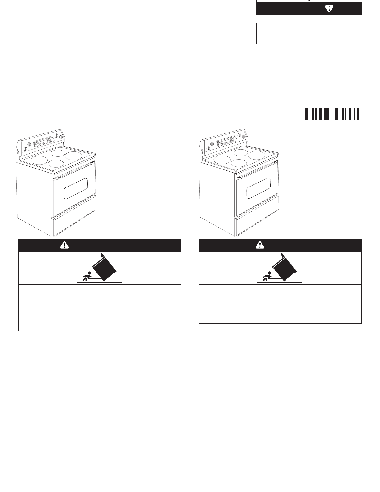
Tip Over Hazard
A child or adult can tip the range and be killed.
Connect anti-tip bracket to rear range foot.
Reconnect the anti-tip bracket, if the range is moved.
Failure to follow these instructions can result in death or serious burns to
children and adults.
WARNING
Tip Over Hazard
A child or adult can tip the range and be killed.
Connect anti-tip bracket to rear range foot.
Reconnect anti-tip bracket, if the range is
moved.
Failure to follow these instructions can result in
death or serious burns to children and adults.
WARNING
9752777C
9752777C
This is the safety alert symbol.
This symbol alerts you to potential hazards
that can kill or hurt you and others.
All safety messages will follow the safety alert symbol
and either the word “DANGER” or “WARNING.”
These words mean:
You can be killed or seriously injured if you don’t
follow instructions.
DANGER
WARNING
Your safety and the safety of others
are very important.
We have provided many important safety messages
in this manual and on your appliance. Always read
and obey all safety messages.
All safety messages will tell you what the potential
hazard is, tell you how to reduce the chance of injury,
and tell you what can happen if the instructions are
not followed.
You can be killed or seriously injured if you don’t
immediately
follow instructions.
When installing a cooktop under existing cabinets and the
installation does not meet the minimum cabinet
clearances, install a range hood above the cooktop to
avoid burn hazards.
IMPORTANT: Observe all governing codes and
ordinances. Failure to meet codes and ordinances could
lead to fire or electrical shock.
Read electrical and carpentry instructions.
Proper installation is your responsibility. A qualified
technician must install this range. Make sure you have
everything necessary for correct installation. It is the
customer’s responsibility to make sure that the installation
clearances specified on the model/serial rating plate are
met. The model/serial rating plate is located on the frame
behind the drawer.
Check location where range will be installed. The range
should be located for convenient use in the kitchen.
Recessed installations must provide complete enclosure
of the sides and rear of range.
All openings in the wall or floor where range is to be
installed must be sealed.
IMPORTANT: Some cabinet and building materials are
not designed to withstand the heat produced by the oven
for baking and self-cleaning. Check with your builder or
cabinet supplier to make sure that the materials used will
not discolor, delaminate or sustain other damage.
Cutout shown is for a 25-inch (63.5 cm) countertop with a
24-inch (61 cm) base cabinet.
Cabinet constructions: This appliance is designed for use
in a base cabinet with a depth of 24 inches (61 cm). The
maximum depth for overhead cabinets is 13 inches
(33 cm). For the minimum vertical clearance between the
cooking surface and the overhead cabinets, see
NOTE***. Overhead cabinets installed at either side of
the appliance must be a minimum of 18 inches (45.7 cm)
above the cooking surface. The minimum horizontal
distance between the overhead cabinets is 30 inches
(76.2 cm).
It is the customer’s responsibility:
To contact a qualified electrical installer.
To assure that the electrical installation is adequate and
in conformance with National Electrical Code,
ANSI/NFPA 70 — latest edition*, or CSA Standard
C22.1, Canadian Electrical Code, Part 1 — latest
edition**, and all local codes and ordinances.
Do not pinch the power supply cord between the range
and the wall.
Do not seal range to side cabinets.
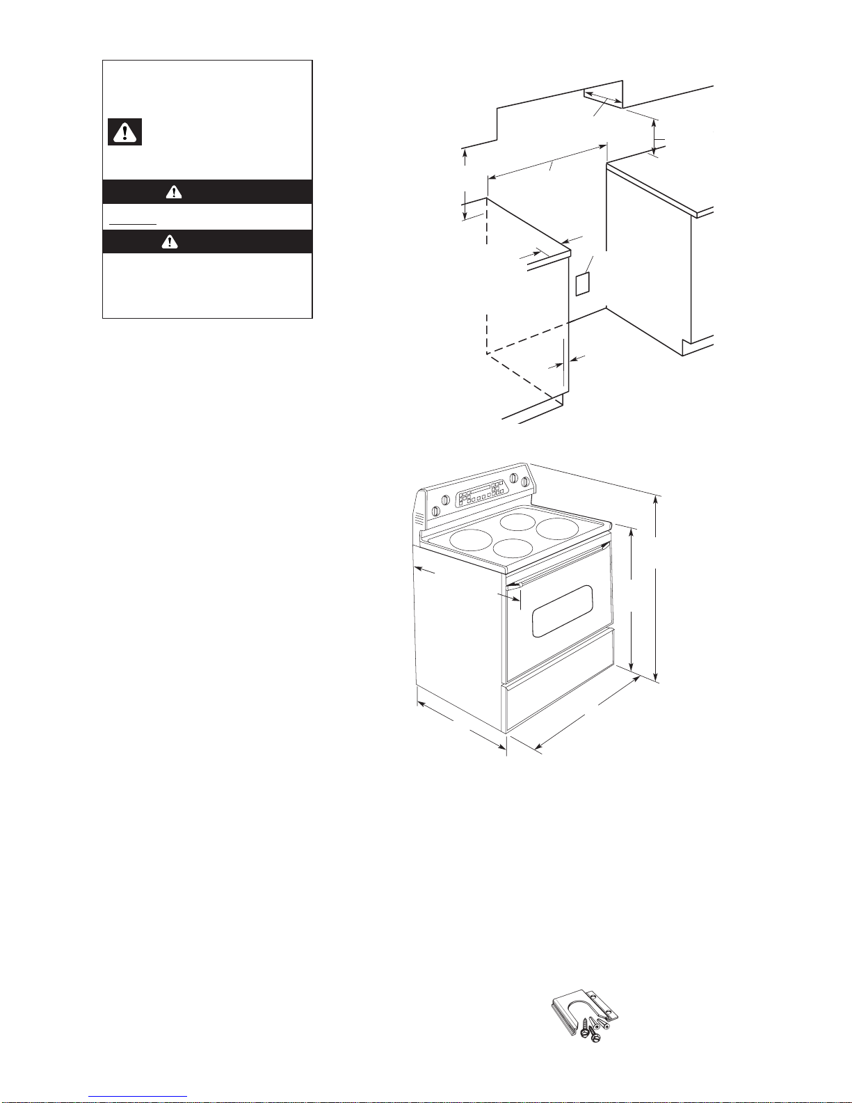
Product dimensions
wall receptacle or junction
box - 8" (20.3 cm) to 22"
(55.9 cm) from either
cabinet, 7" (17.8 cm) max.
from floor.
For minimum
clearance to the
top of the
cooktop, see
NOTE.***
*** NOTE: 24" (61 m) min. when bottom of wood or metal
cabinet is protected by not less than 1/4" (0.64 cm)
flame retardant millboard covered with not less than No.
28 MSG sheet steel, 0.015" (0.4 mm) stainless steel,
0.024" (0.6 mm) aluminum or 0.020" (0/5 cm) copper.
30" (76.2 cm) min. clearance between the top of the
cooking platform and the bottom of an unprotected
wood or metal cabinet.
**** NOTE: This dimension is for the 24" (61 cm) model.
The floor anti-tip bracket must
be installed. To install the antitip bracket shipped with the
range, see Panel B and the antitip bracket template.
Anti-tip bracket:
IMPORTANT:
Observe all governing
codes and ordinances.
Earthed/grounded electrical outlet is
required.
Cabinet opening dimensions that are
shown must be used.
4" (10.2 cm)
min. clearance
from both sides
of range to side
wall or other
combustible
material.
7/8" (2.2 cm) min.
required between
cutout and cabinet
door or hinge.
25" (63.5 cm) countertop depth
24" (61 cm) base cabinet depth
36" (91.4 cm) countertop height
Before you start…
Mobile home installation
The installation of this range must conform to the
Manufactured Home Construction and Safety
Standards, Title 24 CFR, Part 3280 (formerly the
Federal Standard for Mobile Home Construction and
Safety, Title 24, HUD, Part 280); or when such
standard is not applicable, the Standard for
Manufactured Homes Installations (Manufactured
Home Sites, Communities and Setups), ANSI
A225.1/NFPA 501A, or with local codes*.
In Canada, the installation of this range must conform
with the current standard CAN/CSA-Z240 — latest
edition**, or with local codes.
When this range is installed in a mobile home, it must
be secured to the floor during transit. Any method of
securing the range is adequate as long as it conforms
to the standards listed above.
Four-wire power supply cable must abe used in a
mobile home installation. The appliance wiring will
need to be revised.
Copies of the standards listed may be obtained from:
* National Fire Protection Association
Batterymarch Park
Quincy, Massachusetts 02269
** CSA International
8501 East Pleasant Valley Rd.
Cleveland, Ohio 44131-5575
Cabinet opening dimensions
36"
(91.4 cm)
cooktop
height
26-3/8" (67 cm)
depth with handle
26-5/8" (67.6 cm)
for stainless steel
handle (on some
models)
30" (76.2 cm) width for
30" (76.2 cm) range
****24" (61 cm) width for
24" (61 cm) range
24-1/2"
(62.2 cm)
18" (45.7 cm)
upper cabinet
to countertop
46-13/16"
(118.9 cm)
overall
height
13" (33 cm) max.
upper cabinet depth
Panel A
opening widthFor a 30" (76.2 cm) range:
31" (78.7 cm)
For a 24" (61 cm) range:
25" (63.5 cm)
Excessive Weight Hazard
Use two or more people to move and install
range.
Failure to follow this instruction can result in
back or other injury.
Panel B
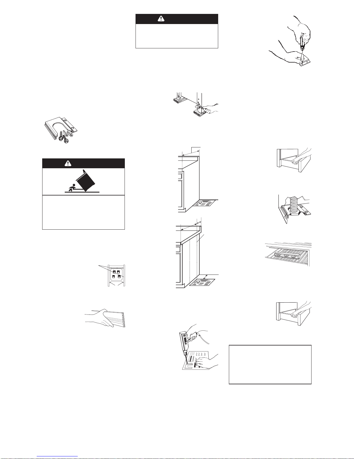
7.Place the range
anti-tip bracket template
on the floor in the cabinet
opening so that the left
edge is against cabinet
and the top edge is
against the rear wall,
molding or cabinet.
2.Take 4 cardboard
corners from the carton.
Stack one cardboard
corner on top of another.
Repeat with the other two
corners. Place corners lengthwise on the floor in back
of range so corners will support outer side edges of
range as shown.
3.Firmly grasp the range and gently lay it on its
back on the cardboard corners.
4.Pull cardboard bottom and shipping base firmly
to remove.
5.Use an
adjustable wrench to
loosen the leveling
legs 1-1/2 turns.
6.Place cardboard or hardboard in front of range.
Stand range back up onto cardboard or hard board.
If countertop opening is
deeper than 25 inches
(63.5 cm), measure and
mark a distance
25 inches (63.5 cm) in
from front of countertop
opening and align
template with mark (or
subtract 25 inches
(63.5 cm) from countertop
depth and add the
difference to the
corresponding
dimension).
If countertop is not flush
to the side of cabinet
opening, align the left
side of the template to
allow for the countertop
overhang. Tape the
range anti-tip bracket template in place.
Contact a qualified floor covering installer for the best
procedure of drilling mounting holes through your type
floor covering.
8.To mount anti-tip
bracket to wood floor, use
the anti-tip bracket
template to mark where to
drill mounting holes. Use
a drill with a 1/8" drill bit
to drill the two holes.
Remove template from
floor.
To mount anti-tip bracket
to concrete or ceramic
floor, use the anti-tip
bracket template to mark where to drill mounting holes.
Use a drill with a 3/16" masonry drill bit to drill the two
holes. Remove template from floor. Tap plastic
anchors into mounting holes in floor with hammer.
9.Line up holes in anti-tip
bracket with holes in floor. Use the
screws provided to fasten anti-tip
bracket to floor.
NOTE: Anti-tip bracket must
be mounted securely to
the sub floor. Depending
on the thickness of your
flooring, longer screws
may be necessary to
anchor the bracket to the
sub floor. Longer screws are
available from your local hardware store.
Before moving, slide range onto cardboard or
hardboard.
11.Remove cardboard or hardboard from
under range. Carefully move range into final position.
1.Remove shipping materials, tape
and protective film from range. Keep
cardboard bottom and shipping base
under range. Remove oven racks, parts
package and all packing materials,
including tape on elements, from inside oven.
10.Move range close to cabinet opening.
Make sure all controls are in the “OFF” position. Make
electrical connection. If the factory installed power
supply cord cannot be plugged into your outlet, have a
qualified electrician install a matching
earthed/grounded outlet. Do not modify the power
supply cord.
12.Press on front of
storage drawer and release to
open. Pull open to first stop
position. Lift front of drawer to
clear white wheels in drawer
guides. Remove drawer and
set it aside on a protected surface.
13.Look under range
(a flashlight may be needed) to
check that left rear leveling leg
is engaged in the anti-tip
bracket. If leveling leg is not
properly engaged, remove and
reposition the anti-tip bracket to
insure that the leveling leg fits
properly in the anti-tip bracket.
14.Place rack
in oven. Place level on
rack, first side to side;
then front to back. If the
range is not level, pull
range forward until the
rear leveling leg is removed from the anti-tip bracket.
Adjust the leveling legs up or down. Then slide range
back into position. Check that leveling leg is engaged
in anti-tip bracket.
NOTE: Oven must be level for satisfactory baking
conditions.
15.Insert storage
drawer into slide rails on
sides of drawer opening.
Lift front of drawer slightly
and push firmly to close drawer.
25" (63.5 cm)
countertop
over 24"
(61 cm)
cabinet
Countertop
overhangs
cabinet
side.
A =Difference
between
countertop
depth and
25" (63.5 cm).
A
25"
(63.5 cm)
A
Tip Over Hazard
A child or adult can tip the range and be killed.
Connect anti-tip bracket to rear range foot.
Reconnect anti-tip bracket, if the range is
moved.
Failure to follow these instructions can result in
death or serious burns to children and adults.
WARNING
Tools needed:
Parts supplied:
Bracket must be securely
mounted to sub-floor.
Thickness of flooring may
require longer screws to
anchor the bracket to subfloor.
anti-tip
bracket
2 screws
(#10 x 1-1/2")
2 plastic
anchors
Now start…
with range in kitchen
spacers
cardboard
corners
To get the most efficient use
from your new range,
read your Use and Care Guide.
Keep Installation Instructions and
Guide close to range
for easy reference.
WARNING
Assemble the required tools and parts before starting
installation. Read and follow the instructions provided
with any tools listed here.
• level
• flat-balde screwdriver or 5/16" nut driver
• Phillips screwdriver
• pliers
• adjustible wrench
• hammer
• measureing tape or ruler
• 3/8" ratchet
• hand or electric drill
wood floor: 1/8" drill bit
concrete/ceramic floor: 3/16" carbide-tipped
masonry drill bit
 Loading...