


Weslo WLEL32115.1 User Manual
weslo.com
Model No. WLEL32115.1
Serial No.
Write the serial number in the space
above for reference.
Serial
Number
Decal
ACTIVATE YOUR
WARRANTY
To register your product and
activate your warranty today,
go to my.weslo.com.
USER’S MANUAL
CUSTOMER CARE
For service at any time, go to
wesloservice.com.
Or call 1-866-699-3756
Mon.–Fri. 6 a.m.–6 p.m. MT
Sat. 8 a.m.–12 p.m. MT
Please do not contact the store.
CAUTION
Read all precautions and
instructions in this manual before
using this equipment. Keep this
manual for future reference.
258868 258869 258870 258871 258872
TABLE OF CONTENTS
WARNING DECAL PLACEMENT . . . . . . . . . . . . . . . . . . . . . . . . . . . . . . . . . . . . . . . . . . . . . . . . . . . . . . . . . . . . . . .2
IMPORTANT PRECAUTIONS ..................................................................3
BEFORE YOU BEGIN. . . . . . . . . . . . . . . . . . . . . . . . . . . . . . . . . . . . . . . . . . . . . . . . . . . . . . . . . . . . . . . . . . . . . . . .5
PART IDENTIFICATION CHART. . . . . . . . . . . . . . . . . . . . . . . . . . . . . . . . . . . . . . . . . . . . . . . . . . . . . . . . . . . . . . . .6
ASSEMBLY . . . . . . . . . . . . . . . . . . . . . . . . . . . . . . . . . . . . . . . . . . . . . . . . . . . . . . . . . . . . . . . . . . . . . . . . . . . . . . . .7
HOW TO USE THE HYBRID TRAINER .........................................................16
FCC INFORMATION . . . . . . . . . . . . . . . . . . . . . . . . . . . . . . . . . . . . . . . . . . . . . . . . . . . . . . . . . . . . . . . . . . . . . . . .20
MAINTENANCE AND TROUBLESHOOTING ....................................................21
EXERCISE GUIDELINES ....................................................................22
PART LIST. . . . . . . . . . . . . . . . . . . . . . . . . . . . . . . . . . . . . . . . . . . . . . . . . . . . . . . . . . . . . . . . . . . . . . . . . . . . . . . .24
EXPLODED DRAWING. . . . . . . . . . . . . . . . . . . . . . . . . . . . . . . . . . . . . . . . . . . . . . . . . . . . . . . . . . . . . . . . . . . . . .26
ORDERING REPLACEMENT PARTS .................................................. Back Cover
LIMITED WARRANTY. . . . . . . . . . . . . . . . . . . . . . . . . . . . . . . . . . . . . . . . . . . . . . . . . . . . . . . . . . . . . . . Back Cover
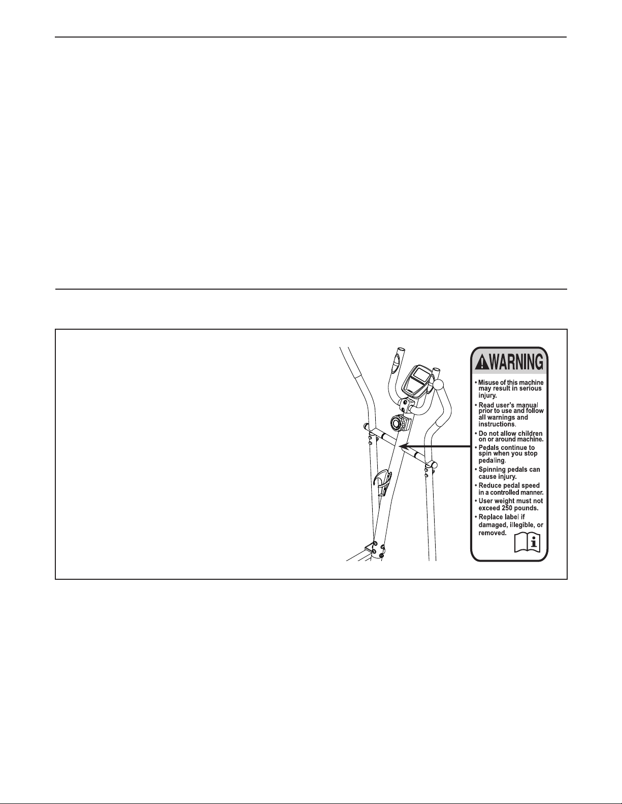
WARNING DECAL PLACEMENT
This drawing shows the location(s) of the warning
decal(s). If a decal is missing or illegible, see
the front cover of this manual and request a
free replacement decal. Apply the decal in the
location shown. Note: The decal(s) may not be
shown at actual size.
WESLO is a registered trademark of ICON Health & Fitness, Inc.
2

IMPORTANT PRECAUTIONS
WARNING: To reduce the risk of serious injury, read all important precautions and
instructions in this manual and all warnings on your hybrid trainer before using your hybrid trainer.
ICON assumes no responsibility for personal injury or property damage sustained by or through the
use of this product.
1. It is the responsibility of the owner to ensure
that all users of the hybrid trainer are adequately informed of all precautions.
2. Before beginning any exercise program,
consult your physician. This is especially
important for persons over age 35 or persons with pre-existing health problems.
3. The hybrid trainer is not intended for use by
persons with reduced physical, sensory, or
mental capabilities or lack of experience and
knowledge, unless they are given supervision or instruction about use of the hybrid
trainer by someone responsible for their
safety.
4. Use the hybrid trainer only as described in
this manual.
5. The hybrid trainer is intended for home use
only. Do not use the hybrid trainer in a commercial, rental, or institutional setting.
6. Keep the hybrid trainer indoors, away from
moisture and dust. Do not put the hybrid
trainer in a garage or covered patio or near
water.
7. Place the hybrid trainer on a level surface,
with at least 3 ft. (0.9 m) of clearance in the
front and rear of the hybrid trainer and 2 ft.
(0.6 m) on each side. To protect the floor or
carpet from damage, place a mat under the
hybrid trainer.
8. Inspect and properly tighten all parts each
time the hybrid trainer is used. Replace any
worn parts immediately.
9. Keep children under age 13 and pets away
from the hybrid trainer at all times.
10. The hybrid trainer should not be used
by persons weighing more than 250 lbs.
(113 kg).
11. Wear appropriate clothes while exercising; do not wear loose clothes that could
become caught on the hybrid trainer. Always
wear athletic shoes for foot protection while
exercising.
12. Hold the handlebars or the upper body arms
when mounting, dismounting, or using the
hybrid trainer.
13. Make sure that the pedal knobs are fully
tightened each time you use the hybrid
trainer.
14. The heart rate monitor is not a medical
device. Various factors may affect the accuracy of heart rate readings. The heart rate
monitor is intended only as an exercise aid
in determining heart rate trends in general.
15. The hybrid trainer does not have a freewheel;
the pedals will continue to move until the
flywheel stops. Reduce your pedaling speed
in a controlled way.
16. Keep your back straight while using the
hybrid trainer; do not arch your back.
17. Over exercising may result in serious injury
or death. If you feel faint, if you become short
of breath, or if you experience pain while
exercising, stop immediately and cool down.
3

STANDARD SERVICE PLANS
all
4
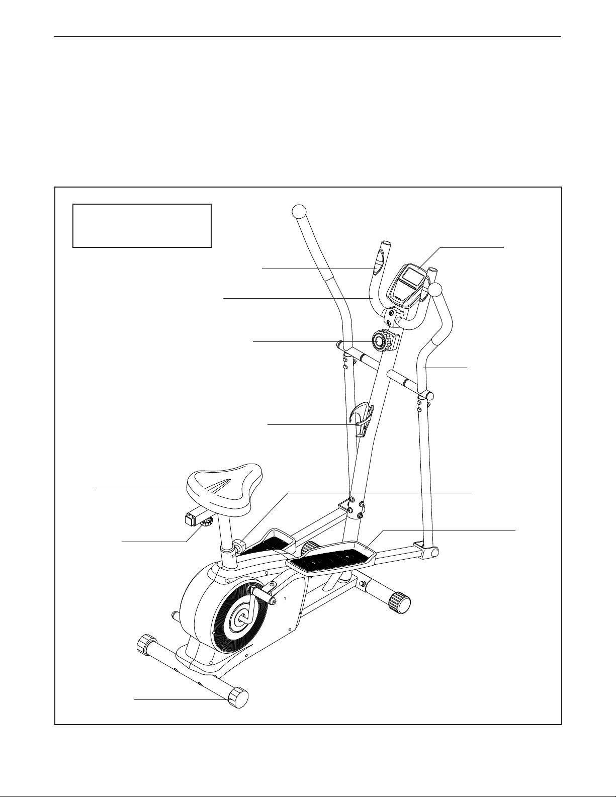
BEFORE YOU BEGIN
Thank you for selecting the revolutionary WESLO®
MOMENTUM G 3.2 hybrid trainer. The MOMENTUM
G 3.2 hybrid trainer provides an impressive selection
of features designed to make your workouts at home
more effective and enjoyable.
For your benefit, read this manual carefully before
you use the hybrid trainer. If you have questions after
Length: 4 ft. 3 in. (130 cm)
Width: 2 ft. 1 in. (64 cm)
Heart Rate Monitor
Handlebar
Resistance Knob
reading this manual, please see the front cover of this
manual. To help us assist you, note the product model
number and serial number before contacting us. The
model number and the location of the serial number
decal are shown on the front cover of this manual.
Before reading further, please familiarize yourself with
the parts that are labeled in the drawing below.
Console
Upper Body Arm
Seat
Seat Knob
Leveling Cap
Water Bottle Holder*
Seat Post Knob
Pedal
*Water bottle is not included
5
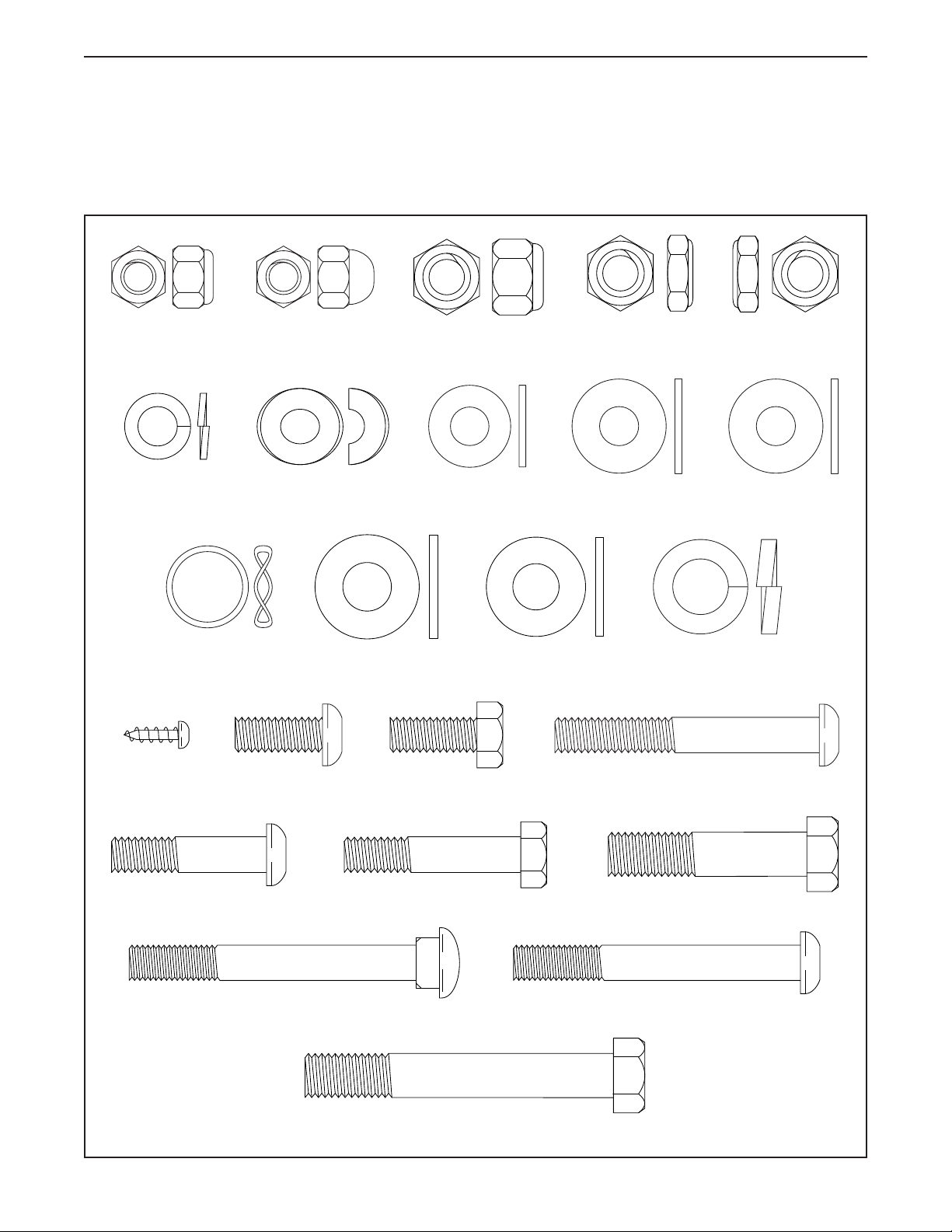
PART IDENTIFICATION CHART
Use the drawings below to identify the small parts needed for assembly. The number in parentheses below each
drawing is the key number of the part, from the PART LIST near the end of this manual. The number following the
key number is the quantity needed for assembly. Note: If a part is not in the hardware kit, check to see if it
has been preassembled. Extra parts may be included.
M8 Locknut
(53)–2
M8 Split
Washer (63)–13
Wave Washer
(73)–2
M4 x 12mm
Screw (66)–6
M8 Acorn Nut
(58)–6
M8 Curved
Washer (101)–2
M8 x 20mm
Screw (54)–3
M10 Washer
(92)–8
M8 x 20mm Hex
Screw (57)–2
M10 Locknut
(93)–6
M8 Washer
(55)–14
M10 Plastic
Washer (62)–4
Left Crank
Locknut (37)–1
M8 Large
Washer (72)–2
M8 x 60mm
Bolt (90)–2
Right Crank
Locknut (36)–1
M8 Plastic
Washer (27)–2
M12 Split
Washer (74)–2
M8 x 35mm Screw (86)–2
M8 x 65mm Carriage Bolt (51)–2
M8 x 40mm Bolt (56)–4
M10 x 70mm Bolt (60)–2
6
M10 x 45mm Bolt (91)–4
M8 x 65mm Bolt (100)–2
ASSEMBLY
• To hire an authorized service technician to
assemble the hybrid trainer, call 1-800-445-2480.
• Assembly requires two persons.
• Place all parts in a cleared area and remove the
packing materials. Do not dispose of the packing
materials until you nish assembly.
• Left parts are marked “L” or “Left” and right parts
are marked “R” or “Right.”
• To identify small parts, see page 6.
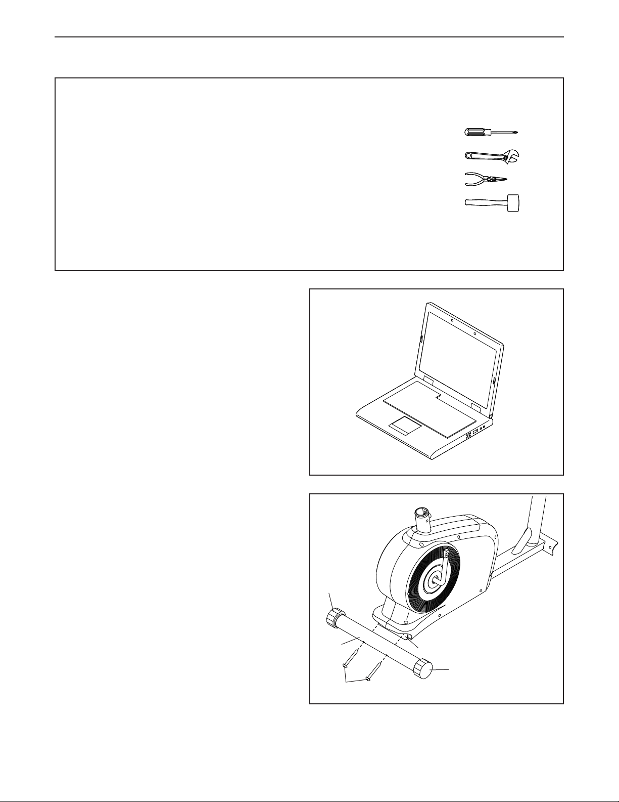
1. Go to my.weslo.com on your computer and
register your product.
• documents your ownership
• activates your warranty
• ensures priority customer support if assistance
is ever needed
• In addition to the included tool(s), assembly
requires the following tools:
one Phillips screwdriver
one adjustable wrench
one pair of pliers
one rubber mallet
Assembly may be easier if you have a set of
wrenches. To avoid damaging parts, do not use
power tools.
1
Note: If you do not have internet access, call
Customer Care (see the front cover of this
manual) and register your product.
2. Identify the Rear Stabilizer (28), which has a
Leveling Cap (33) on each end.
While a second person lifts the rear of the Frame
(1), attach the Rear Stabilizer (28) to the Frame
with two M8 x 65mm Bolts (100); start both
Bolts, and then tighten them.
2
33
28
100
1
33
7
3. While a second person lifts the front of the
Frame (1), attach the Front Stabilizer (10) to
the Frame with two M8 x 65mm Carriage Bolts
(51), two M8 Curved Washers (101), two M8
Split Washers (63), and two M8 Acorn Nuts (58);
insert both Carriage Bolts, and then tighten
the Acorn Nuts.
3
58
63
101
58
1
63
10
51
101
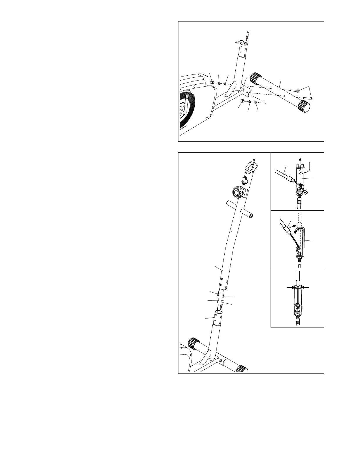
4. While a second person holds the Upright (2)
near the Frame (1), connect the Upright Wire
(31) to the Reed Switch Wire (47).
Next, connect the Resistance Cable (25) to the
Lower Cable (42) in the following way:
See inset drawing A. Pull upward on the metal
bracket on the Lower Cable (42), and insert the
tip of the Resistance Cable (25) into the wire clip
inside the metal bracket.
See inset drawing B. Firmly pull the Resistance
Cable (25) and slide it into the metal bracket on
the Lower Cable (42).
See inset drawing C. Using pliers, squeeze
together the prongs on the upper end of the
metal bracket.
4
2
31
47
1
25
42
A
25
42
B
25
42
C
8
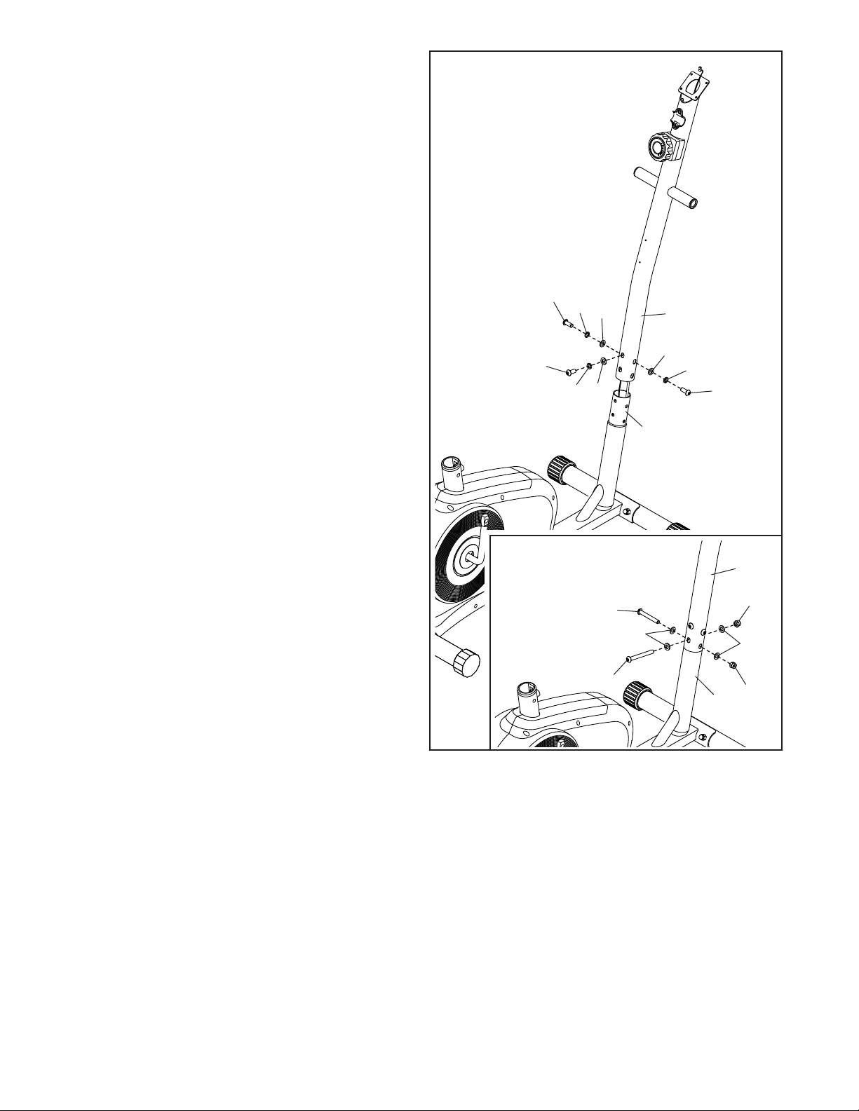
5. Tip: Avoid pinching the wires and cables
during this step.
Slide the Upright (2) onto the Frame (1).
Attach the Upright (2) with three M8 x 20mm
Screws (54), three M8 Split Washers (63), and
three M8 Washers (55). Do not tighten the
Screws yet.
See the inset drawing. Attach the Upright
(2) with two M8 x 60mm Bolts (90), four M8
Washers (55), and two M8 Locknuts (53). Do
not tighten the Locknuts yet.
5
Avoid pinching the
wires and cables
54
54
63
63
55
55
2
55
63
54
1
90
90
55
2
53
55
53
1
9
 Loading...