

Page 1
Video Colposcope
Colposcope vidéo/Videocolposcopio
Videokolposkop/Videocolposcopio
Videokolposkop/Videocolposcoop
Colposcópio Vídeo/Videokolposkop
REF 88000A/88001A/89000A/88007/89001A/88007/88002A/88004A/88006A/89006
Directions for Use ....................................................................... 1
Mode d’emploi ........................................................................... 45
Instrucciones de uso ................................................................ 89
Gebrauchsanleitung ............................................................... 133
Istruzioni per l’uso ................................................................... 177
Bruksanvisning ........................................................................ 221
Gebruikshandleiding ............................................................... 265
Instruções de utilização ......................................................... 309
Brugsanvisning ........................................................................ 353
Page 2

Page 3

Video Colposcope
Directions for Use
REF 88000A/88001A/89000A/88007/89001A/88007/88002A/88004A/88006A/89006A
Page 4

2 Welch Allyn Video Colposcope
Copyright 2005 Welch Allyn. All rights are reserved. No one is permitted to reproduce or duplicate, in any
form, this manual or any part thereof without permission from Welch Allyn.
Welch Allyn assumes no responsibility for any injury to anyone, or for any illegal or improper use of the
product, that may result from failure to use this product in accordance with the instructions, cautions,
warnings, or statement of intended use published in this manual.
Welch Allyn
®
is a registered trademark of Welch Allyn.
For information about any Welch Allyn product, call Welch Allyn Technical Support:
USA +1 800 535 6663
+1 315 685 4560
Canada +1 800 561 8797 China +86 21 6327 9631
European Call Center +353 46 90 67790 France +33 1 60 09 33 66
Germany +49 7477 9271 70 Japan +81 3 3219 0071
Latin America +1 305 669 9003 Netherlands +31 157 505 000
Singapore +65 6419 8100 South Africa +27 11 777 7555
United Kingdom +44 207 365 6780 Sweden +46 85 853 6551
Manual Part Number 880332 Ver. C
Welch Allyn
4341 State Street Road
Skaneateles Falls, NY 13153 USA
www.welchallyn.com
Printed in USA
Australia +61 2 9638 3000
Page 5

Contents
1 - Introduction . . . . . . . . . . . . . . . . . . . . . . . . . . . . . . . . . . . . . . . . . . . . . 5
2 - Components . . . . . . . . . . . . . . . . . . . . . . . . . . . . . . . . . . . . . . . . . . . . 9
3
Indications For Use . . . . . . . . . . . . . . . . . . . . . . . . . . . . . . . . . . . . . . . . . . . . . . . . 5
Symbols . . . . . . . . . . . . . . . . . . . . . . . . . . . . . . . . . . . . . . . . . . . . . . . . . . . . . . . . 5
Warnings and Cautions. . . . . . . . . . . . . . . . . . . . . . . . . . . . . . . . . . . . . . . . . . . . . 6
Warnings . . . . . . . . . . . . . . . . . . . . . . . . . . . . . . . . . . . . . . . . . . . . . . . . . . . . 6
Cautions . . . . . . . . . . . . . . . . . . . . . . . . . . . . . . . . . . . . . . . . . . . . . . . . . . . . . 7
Video Colposcope . . . . . . . . . . . . . . . . . . . . . . . . . . . . . . . . . . . . . . . . . . . . . . . . . 9
Front View. . . . . . . . . . . . . . . . . . . . . . . . . . . . . . . . . . . . . . . . . . . . . . . . . . . . . . 11
Side Views . . . . . . . . . . . . . . . . . . . . . . . . . . . . . . . . . . . . . . . . . . . . . . . . . . . . . 12
Back View . . . . . . . . . . . . . . . . . . . . . . . . . . . . . . . . . . . . . . . . . . . . . . . . . . . . . . 13
Bottom View . . . . . . . . . . . . . . . . . . . . . . . . . . . . . . . . . . . . . . . . . . . . . . . . . . . . 13
Vertical Stand . . . . . . . . . . . . . . . . . . . . . . . . . . . . . . . . . . . . . . . . . . . . . . . . . . . 14
Swing Arm Stand . . . . . . . . . . . . . . . . . . . . . . . . . . . . . . . . . . . . . . . . . . . . . . . . 14
Monitor . . . . . . . . . . . . . . . . . . . . . . . . . . . . . . . . . . . . . . . . . . . . . . . . . . . . . . . . 15
Printer . . . . . . . . . . . . . . . . . . . . . . . . . . . . . . . . . . . . . . . . . . . . . . . . . . . . . . . . . 16
3 - Connections and Assembly . . . . . . . . . . . . . . . . . . . . . . . . . . . . . . . 17
Connecting Video Colposcope with Monitor . . . . . . . . . . . . . . . . . . . . . . . . . . . 17
Connecting Video Colposcope with Optional VCR/Video Printer . . . . . . . . . . . . 18
Assembly . . . . . . . . . . . . . . . . . . . . . . . . . . . . . . . . . . . . . . . . . . . . . . . . . . . . . . 19
General Precautions . . . . . . . . . . . . . . . . . . . . . . . . . . . . . . . . . . . . . . . . . . . 19
Video Colposcope. . . . . . . . . . . . . . . . . . . . . . . . . . . . . . . . . . . . . . . . . . . . . 19
Vertical Stand Assembly. . . . . . . . . . . . . . . . . . . . . . . . . . . . . . . . . . . . . . . . 20
Swing Arm Stand Assembly. . . . . . . . . . . . . . . . . . . . . . . . . . . . . . . . . . . . . 20
Setting Up Video Colposcope. . . . . . . . . . . . . . . . . . . . . . . . . . . . . . . . . . . . 22
4 - Operation . . . . . . . . . . . . . . . . . . . . . . . . . . . . . . . . . . . . . . . . . . . . . . 23
Power Switch . . . . . . . . . . . . . . . . . . . . . . . . . . . . . . . . . . . . . . . . . . . . . . . . . . . 23
Lamp Ignition . . . . . . . . . . . . . . . . . . . . . . . . . . . . . . . . . . . . . . . . . . . . . . . . . . . 23
Focus and Zoom Controls. . . . . . . . . . . . . . . . . . . . . . . . . . . . . . . . . . . . . . . . . . 23
Mag Index Control . . . . . . . . . . . . . . . . . . . . . . . . . . . . . . . . . . . . . . . . . . . . . . . 24
Green Filter Control . . . . . . . . . . . . . . . . . . . . . . . . . . . . . . . . . . . . . . . . . . . . . . 24
Polarization Filter Control . . . . . . . . . . . . . . . . . . . . . . . . . . . . . . . . . . . . . . . . . . 24
Illumination Beam Director . . . . . . . . . . . . . . . . . . . . . . . . . . . . . . . . . . . . . . . . . 24
Vertical Height Adjustment Ring (Vertical Colposcope Model Only) . . . . . . . . . . 25
Swing Arm Height Adjustment (Swing Arm Colposcope Model Only). . . . . . . . 25
Positioning Video Colposcope. . . . . . . . . . . . . . . . . . . . . . . . . . . . . . . . . . . . . . . 25
Page 6

4 Contents Welch Allyn Video Colposcope
Remote Video Functions. . . . . . . . . . . . . . . . . . . . . . . . . . . . . . . . . . . . . . . . . . . 25
5 - Maintenance . . . . . . . . . . . . . . . . . . . . . . . . . . . . . . . . . . . . . . . . . . . 27
Disinfecting Solutions . . . . . . . . . . . . . . . . . . . . . . . . . . . . . . . . . . . . . . . . . . . . . 27
Video Colposcope Cleaning . . . . . . . . . . . . . . . . . . . . . . . . . . . . . . . . . . . . . . . . 27
Lens Cleaning . . . . . . . . . . . . . . . . . . . . . . . . . . . . . . . . . . . . . . . . . . . . . . . . . . . 27
Camera Lens . . . . . . . . . . . . . . . . . . . . . . . . . . . . . . . . . . . . . . . . . . . . . . . . 27
Illumination Beam Director Lens . . . . . . . . . . . . . . . . . . . . . . . . . . . . . . . . . 28
Replacing Lamp . . . . . . . . . . . . . . . . . . . . . . . . . . . . . . . . . . . . . . . . . . . . . . . . . 28
Replacing Fuses . . . . . . . . . . . . . . . . . . . . . . . . . . . . . . . . . . . . . . . . . . . . . . . . . 30
Troubleshooting . . . . . . . . . . . . . . . . . . . . . . . . . . . . . . . . . . . . . . . . . . . . . . . . . 31
6 - Specifications . . . . . . . . . . . . . . . . . . . . . . . . . . . . . . . . . . . . . . . . . . 33
Video Colposcope . . . . . . . . . . . . . . . . . . . . . . . . . . . . . . . . . . . . . . . . . . . . . . . . 33
Video Monitor . . . . . . . . . . . . . . . . . . . . . . . . . . . . . . . . . . . . . . . . . . . . . . . . . . . 34
Agency Approvals . . . . . . . . . . . . . . . . . . . . . . . . . . . . . . . . . . . . . . . . . . . . . . . . 35
Guidance and Manufacturer’s Declaration . . . . . . . . . . . . . . . . . . . . . . . . . . . . . 36
Emissions and Immunity Information . . . . . . . . . . . . . . . . . . . . . . . . . . . . . 36
7 - Service . . . . . . . . . . . . . . . . . . . . . . . . . . . . . . . . . . . . . . . . . . . . . . . . 41
Technical Assistance . . . . . . . . . . . . . . . . . . . . . . . . . . . . . . . . . . . . . . . . . . 41
Service Manual/Spare Parts . . . . . . . . . . . . . . . . . . . . . . . . . . . . . . . . . . . . . 41
Warranty . . . . . . . . . . . . . . . . . . . . . . . . . . . . . . . . . . . . . . . . . . . . . . . . . 43
Page 7
5
1
Introduction
Thank you for purchasing the Welch Allyn Video Colposcope. Follow the operation and
maintenance instructions found in this manual and your Video Colposcope will provide
you with many years of reliable service. Please read these instructions thoroughly before
attempting to use your new Video Colposcope.
IMPORTANT: The material outlined in this manual should be reviewed and understood
prior to operation of the equipment.
Indications For Use
For examination of the tissues of the vagina, cervix, and external genitalia, to investigate,
by means of magnification, abnormal cervical cytology or suspicious lesions of the lower
female genital tract. Also used for corresponding biopsy and treatment, when indicated.
Symbols
On: Power: Connects to
the low voltage supply.
Off: Power: Disconnects
from the low voltage supply.
Attention: Consult user’s
manual for additional
information.
High temperatures Caution: A caution statement in
Risk of fire. Replace fuses
as marked.
Power supply of unit is
energized whenever power
cord is plugged in.
Warning: A warning statement in
this manual identifies a condition
or practice, which if not corrected
or discontinued immediately,
could lead to patient injury, illness,
or death.
this manual identifies a condition
or practice, which if not corrected
or discontinued immediately,
could lead to equipment failure,
equipment damage, or data loss.
High-intensity light
Type B Equipment
Page 8

6 Introduction Welch Allyn Video Colposcope
Warnings and Cautions
Familiarize all operating personnel with the general safety information in this summary.
Specific warnings and cautions are also found throughout this manual.
Warnings
A warning statement in this manual identifies a condition or practice, which if not
corrected or discontinued immediately, could lead to patient injury, illness, or death.
WARNING Users of this equipment should be thoroughly trained in the
appropriate medical procedures. Furthermore, they should take the time to
read and understand these instructions before performing any procedure. They
should also read and understand the instructions for any other equipment used in
conjunction with the Video Colposcope (i.e. electrosurgical generators). Failure to
do so may result in injury to the patient and/or damage to the Video Colposcope.
WARNING The Video Colposcope should not be operated in the presence of
flammable or explosive gases (i.e., anesthetics) or chemicals, or installed in areas
where these materials are commonly used.
WARNING Keep all liquids away from electrical equipment to avoid the
possibility of shock and instrument damage.
WARNING The lamp is extremely bright. DO NOT stare directly into illumination
lens when the lamp is lit.
WARNING Video Colposcope user should adhere to the operating conditions
found in this manual. Otherwise, instrument damage may occur and/or operator/
patient safety may be compromised.
WARNING All signal input and output (I/O) connectors are intended for
connection to only peripheral devices (example: monitor, video printer, VCR, PC,
DV Converter) that are in compliance with IEC 60601-1 (General Requirements
for Safety, Medical Electrical Equipment) or other IEC standards (for example
IEC 60950, Information Technology Equipment – Safety) as appropriate to the
nature of the peripheral device. Connecting additional peripherals to the Video
Colposcope may increase the risk associated with chassis or patient leakage
currents. To maintain operator and patient safety, the User should consider
the system leakage current requirements of IEC 60601-1-1 (Medical Electrical
Equipment, Safety Requirements for Medical Electrical Systems). The user
should measure leakage currents accordingly to confirm that no electric shock
hazard exists. An isolation transformer that is in compliance with IEC 60601-1
used to power the additional peripherals may be used to control the system
leakage current to comply with the requirements of IEC 60601-1-1.
WARNING If peripheral devices (example: monitor, video printer, VCR ,other)
do not comply with IEC 60601-1-1 (Medical Electrical Equipment, Safety
Requirements for Medical Electrical systems), they must be kept out of the
patient area (6 feet minimum from patient).
WARNING DO NOT use a converter adapter that will convert the three-prong
AC plug to a two-prong line plug. The power supply in the Video Colposcope will
not be properly grounded and electric shock might result.
Page 9

Directions for Use Introduction 7
WARNING For safety, the Video Colposcope should only be coupled to a
grounded 110–120 VAC hospital-grade outlet (220–240 volt, 50 cycle
international).
WARNING The lamp operates at a high temperature. DO NOT attempt to
remove the lamp before allowing it to cool. Allow at least five minutes for the
lamp to cool before replacing. Replace with Welch Allyn lamp #09800-U only.
Cautions
A caution statement in this manual identifies a condition or practice, which if not
corrected or discontinued immediately, could lead to equipment failure, equipment
damage, or data loss.
Caution Federal law restricts sale of this device to, or to the order of, a
physician or other appropriately licensed medical professional.
Caution Occasionally inspect the power cord for signs of cuts, abrasions or
dents.
Caution The Video Colposcope should never be stored or operated in areas
where it could get wet or could be exposed to any environmental conditions like
extreme temperature or humidity, direct sunlight, dust, etc.
Caution All service to the Video Colposcope must be performed by Welch Allyn
or by an authorized repair center.
Caution There are no user servicable parts (other than the lamp and fuses) in
this unit or in its accessories. Any attempt to disassemble and/or repair this unit
will result in voiding of the warranty.
Caution The Video Colposcope is cooled via a fan located in the back of the
unit. The fan draws air in from beneath the Video Colposcope and exhausts the
air out the back of the Video Colposcope. To avoid overheating, verify that the
unit is no less than 6" from a wall.
Caution Do not clean illumination lens with alcohol. Do not touch optical or
illumination lenses except as described in Maintenance section of this manual.
Caution The colposcope can be damaged if the unit is transported while
holding the handle. The unit should be transported by grasping the pole.
Caution Do not sterilize.
Caution Do not spray or allow solution to drip into the air vents.
Caution Do not immerse any part of the unit in cleaning solutions.
Page 10

8 Introduction Welch Allyn Video Colposcope
Page 11
9
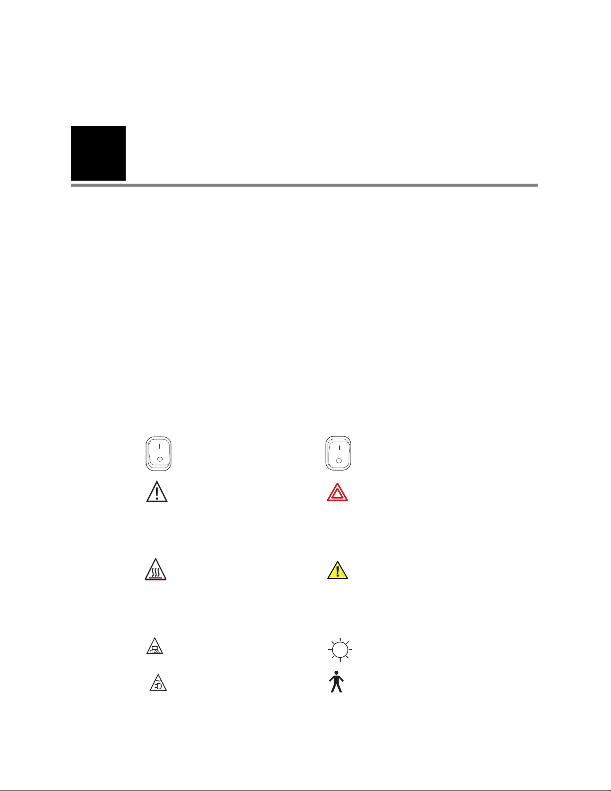
88000A
89000A
Video Colposcope and vertical stand
with vertical stand hardware kit:
• Allen wrench
• Allen bolt
• Mounting washer
• Spacer
Video Colposcope and swing arm
stand with swing arm hardware kit:
• Allen wrench
•Bolt
2
Components
Video Colposcope
Page 12
10 Components Welch Allyn Video Colposcope
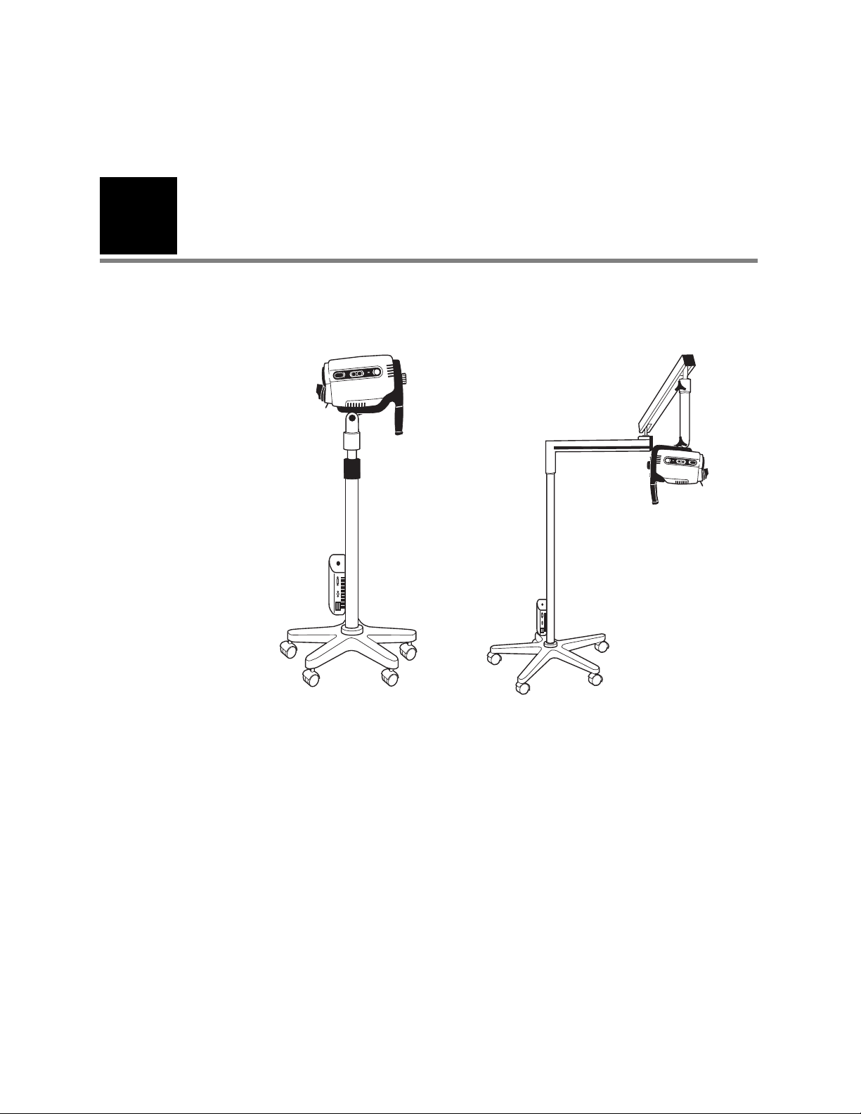
All illustrations are for reference only.
88600
S-Video Cable
761076-0
Power Cord
Optional Accessories
09800-U
Replacement Lamp
88500
RS-232 Interface Cable
488307-9
Replacement Fuse (2 required)
88010
Cervical Model
88040
Dust Cover for Vertical Stand
89040
Dust Cover for Swing Arm
Page 13
Directions for Use Components 11
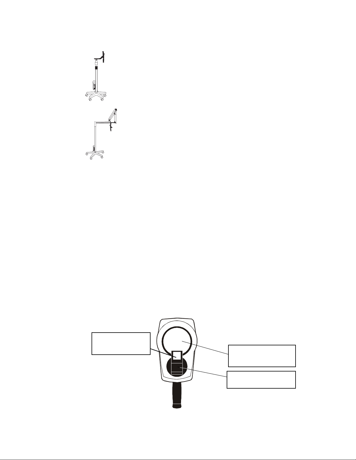
Illumination Beam Director.
Directs lamp beam.
Camera Lens. The lens that
establishes the magnification
and field of view.
Illumination Beam
Director Lens. Provides
light for the examination.
Note
88030
Vertical Stand with Base Only
89030
Swing Arm Stand with Base Only
Monitor. For specifications see “Video Monitor” on
page 34. Contact Welch Allyn for details.
Front View
VCR/Printer. Contact Welch Allyn for details.
Image Capture System. Contact Welch Allyn for details.
Only accessories and components indicated in this manual are to be used with
the Welch Allyn Video Colposcope system.
Page 14
12 Components Welch Allyn Video Colposcope
FINE
FINE
MAG
INDEX
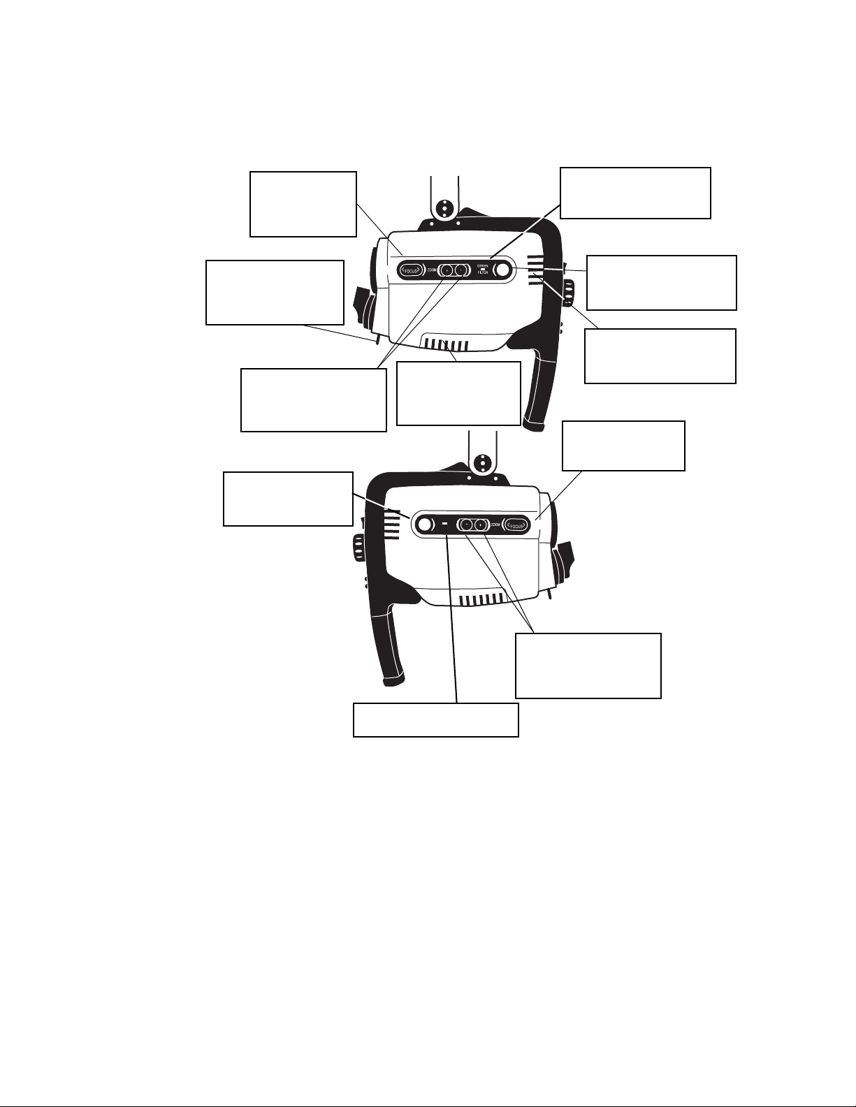
Zoom control button.
Pressing + or - increases or
decreases magnification
accordingly.
Ventilation slots.
Allow air to enter and
leave unit, cooling
internal components.
Green filter LED indicator.
Illuminates if the electronic
green filter is on.
Ventilation slots. Allow air
to enter and leave unit,
cooling internal components.
Green filter button.
Pressing turns the electronic
green filter on or off.
Fine Focus
control button.
Pressing < or >
adjusts the focus.
Zoom control button.
Pressing + or - increases or
decreases magnification
accordingly.
Fine Focus control
button. Pressing < or >
adjusts the focus.
Polarization filter
control. Adjusts the
proportion of glare
removed from the image.
Mag button. Displays
magnification index on
screen.
Mag LED indicator.
Illuminates if Mag Index is on.
Side Views
Page 15
Directions for Use Components 13
F
C
V
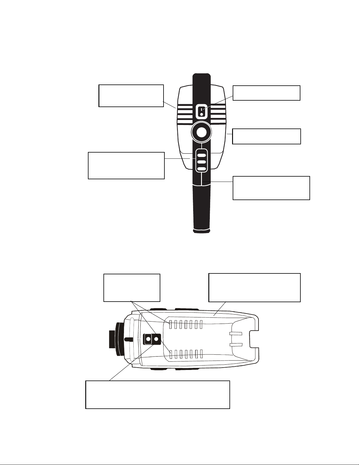
Attachment knob. Fastens
handle to Video Colposcope.
Video Colposcope handle. For
positioning the colposcope in the
proper up/down, left/right position.
Remote video function buttons.
Allows use of remote printing and
saving functions with appropriate
accessory device.
Ventilation slots. Allow air
to enter and leave unit,
cooling internal components.
Power switch. Power control
for the Video Colposcope.
Lamp access door. Removes for lamp
replacement. (Note: If door is not properly
closed, interlock power switches will not
activate and the lamp will not start.)
Mounting piece. Allows the Video Colposcope to attach to the stand.
On the swing arm model, the mounting piece is located at the top of
the colposcope. On the vertical stand model, the mounting piece is
located at the bottom of the colposcope.
Ventilation slots.
Allow air to enter and
leave unit, cooling
internal components.
Back View
Bottom View
Page 16
14 Components Welch Allyn Video Colposcope
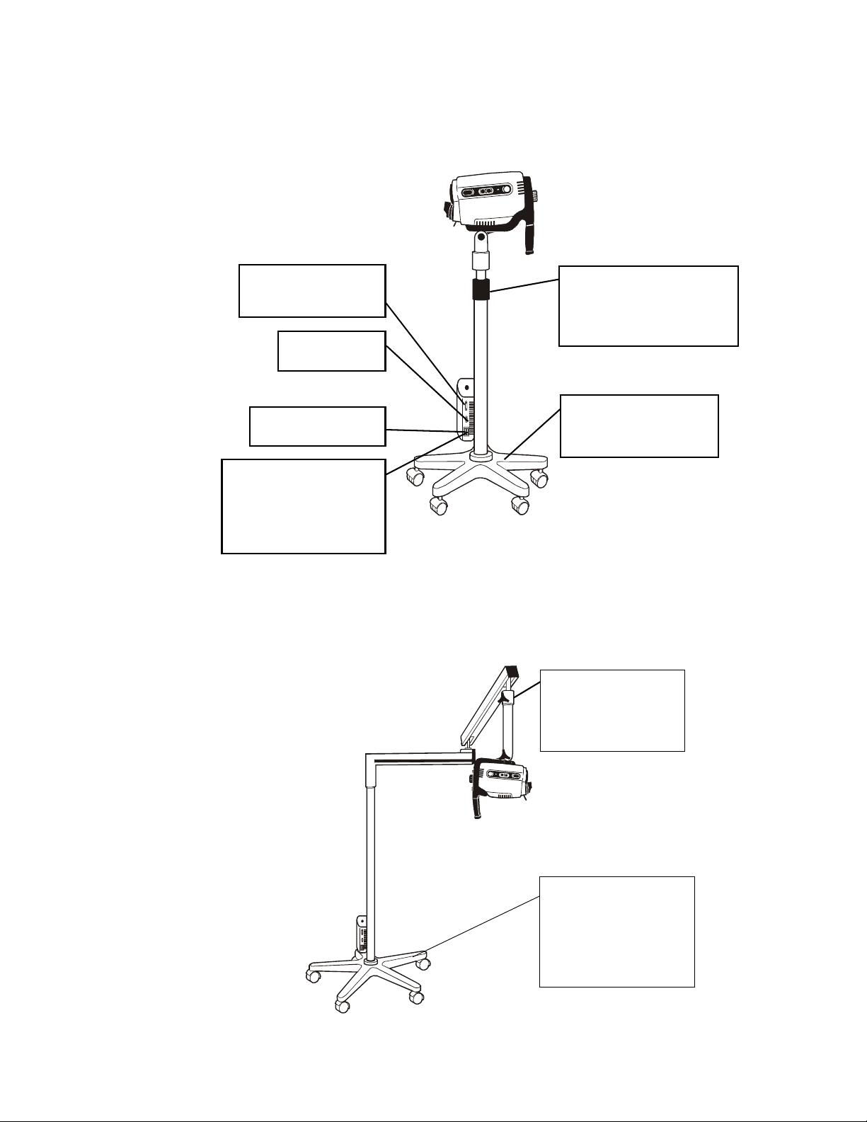
Vertical rolling base stand.
Allows mobility with 5-caster
base, including two locking
casters.
Fuse drawer. Opens for
replacement of fuses.
Power supply cord
receptacle. Couples with
power cord, which should be
plugged into a 110–120 VAC
hospital-grade outlet
(220–240 volt, 50 cycle
S-Video output.
Outputs S-Video.
RS232 interface cable
connector. Couples with
RS-232 interface cable.
Height adjustment ring.
Allows vertical movement
and locking of stand at desired
height;vertical height adjustment
36"–46" (91.4 cm to 116.8 cm).
Swing arm rolling base
stand. Allows overhead
positioning of the instrument
with 5-caster weighted base,
including two locking casters;
vertical height 29.5" to 49.5"
(74.9 cm to 125.7 cm).
Height adjustment knob.
Allows adjustment of arm
tension and vertical height
adjustment 26.5" to 45.5"
(67.3 cm to 115.6 cm).
Vertical Stand
Swing Arm Stand
Page 17
Directions for Use Components 15
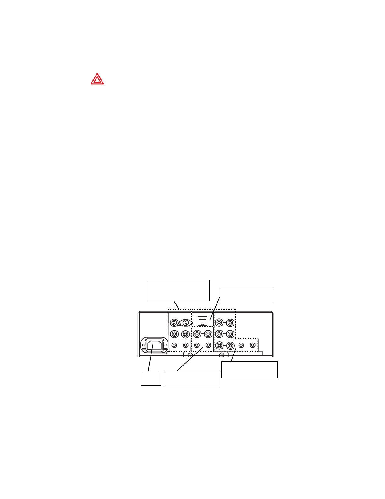
LINE A
PARALLEL REMOTE
RGB/COMPONENT
LINE B
~AC IN
IN
IN
IN
IN
IN
IN
IN
IN
IN
OUT
OUT
OUT
OUT
OUT
OUT
OUT
OUT
OUT
VIDEO
S-VIDEO
G/Y
B/Pb
R/Pr
VIDEO
AUDIO
AUDIO
AUDIO
AC IN
socket
LINE A [S-Video composite
(BNC), (4 pin mini-DIN),
Audio (RCA pin)]
LINE B [composite
(BNC), Audio (RCA pin)]
PARALLEL REMOTE
(modular connector)
RGB/COMPONENT
(BNC), Aduio (RCA pin)
Note
Monitor
WARNING If peripheral devices (example: monitor, video printer, VCR ,other) do
not comply with IEC 60601-1-1, they must be kept out of the patient area (6 feet
minimum from patient).
WARNING All signal input and output (I/O) connectors are intended for
connection to only peripheral devices (example: monitor, video printer, VCR)
that are in compliance with IEC 60601-1 (General Requirements for Safety,
Medical Electrical Equipment) or other IEC standards (for example IEC 60950,
Information Technology Equipment – Safety) as appropriate to the nature of the
peripheral device. Connecting additional peripherals to the Video Colposcope
may increase the risk associated with chassis or patient leakage currents.
To maintain operator and patient safety, the User should consider the system
leakage current requirements of IEC 60601-1-1 (Medical Electrical Equipment,
Safety Requirements for Medical Electrical Systems). The user should measure
leakage currents accordingly to confirm that no electric shock hazard exists.
An isolation transformer that is in compliance with IEC 60601-1 used to power
the additional peripherals may be used to control the system leakage current
to comply with the requirements of IEC 60601-1-1.
Image is for reference only. Actual monitor may vary. Monitor shown is
SONY LMD-1410.
Use the video monitor provided by Welch Allyn or any video monitor that meets
the specifications listed on page 34.
For detailed instructions, please refer to the provided manufacturer’s operation
manual.
Page 18
16 Components Welch Allyn Video Colposcope
NTSC
PAL
REMOTE
12
~AC IN
RS-2232C
INPUT
OUTPUT
S-VIDEO
S-VIDEO
VIDEO
VIDEO
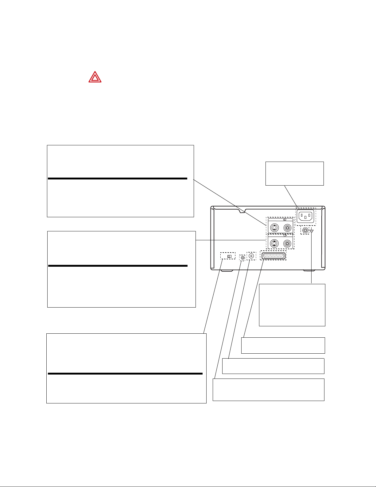
Input Connectors. To connect the video equipment supplying the
source image.
Connector Connectable Equipment
S-VIDEO Equipment with a S-Video (Y/C) output
connector
VIDEO Equipment with a composite video signal
output connector
Output Connectors. To connect the video monitor. Refer to “Important
safeguards/notices for use in the medical environments.”
Connector Connectable Equipment
S-VIDEO Video Monitor with a S-Video (Y/C)
separated input connector
VIDEO Video Monitor with a composite video signal
input connector
~ AC IN. To connect the
printer to a wall outlet
with the supplied cord.
Equipotential Ground
Terminal Connector.
To connect to the
equipotential plug to bring
the various parts of a system
to the same potential.
RS-232C Connector. To connect the
Video Colposcope to control the printer.
NTSC/PAL (TV) Selector. Set this selector according to the TV system of the
input signal. If you change this setting, turn the printer power off and then back
on again.
Selector position When
NTSC NTSC system video equipment is connected.
PAL PAL system video equipment is connected.
Remote 1 Connector. To connect an RM-5500
Remote Control Unit (not supplied) to be used as
a wired remote control unit.
Remote 2 Connector. To connect an RM-91
Remove Control Unit (not supplied).
Note
Printer
WARNING If peripheral devices (example: monitor, video printer, VCR ,other) do
not comply with IEC 60601-1-1, they must be kept out of the patient area (6 feet
minimum from patient).
For detailed instructions, please refer to the printer operation manual that has
been provided by the manufacturer. Printer shown is SONY UP-20; this is for
reference only.
Page 19
17
LINEA
PARALLEL REMOTE
RGB/COMPONENT
LINE B
~AC IN
IN
IN
IN
IN
IN
IN
IN
IN
IN
OUT
OUT
OUT
OUT
OUT
OUT
OUT
OUT
OUT
VIDEO
S-VIDEO
G/Y
B/Pb
R/Pr
VIDEO
AUDIO
AUDIO
AUDIO
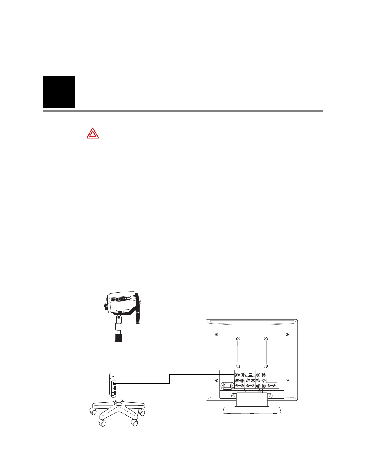
S-Video Cable to Monitor
Line A S-Video (Y/C) In
Back Panel of Monitor
3
Connections and Assembly
WARNING If peripheral devices (example: monitor, video printer, VCR ,other) do
not comply with IEC 60601-1-1, they must be kept out of the patient area (6 feet
minimum from patient).
WARNING All signal input and output (I/O) connectors are intended for
connection to only peripheral devices (example: monitor, video printer, VCR)
that are in compliance with IEC 60601-1 (General Requirements for Safety,
Medical Electrical Equipment) or other IEC standards (for example IEC 60950,
Information Technology Equipment – Safety) as appropriate to the nature of the
peripheral device. Connecting additional peripherals to the Video Colposcope
may increase the risk associated with chassis or patient leakage currents.
To maintain operator and patient safety, the User should consider the system
leakage current requirements of IEC 60601-1-1 (Medical Electrical Equipment,
Safety Requirements for Medical Electrical Systems). The user should measure
leakage currents accordingly to confirm that no electric shock hazard exists.
An isolation transformer that is in compliance with IEC 60601-1 used to power
the additional peripherals may be used to control the system leakage current to
comply with the requirements of IEC 60601-1-1.
Connecting Video Colposcope with Monitor
Page 20
18 Connections and Assembly Welch Allyn Video Colposcope
NTSC
PAL
REMOTE
12
~AC IN
RS-2232C
INPUT
OUTPUT
S-VIDEO
S-VIDEO
VIDEO
VIDEO
LINEA
PARALLEL REMOTE
RGB/COMPONENT
LINE B
~AC IN
IN
IN
IN
IN
IN
IN
IN
IN
IN
OUT
OUT
OUT
OUT
OUT
OUT
OUT
OUT
OUT
VIDEO
S-VIDEO
G/Y
B/Pb
R/Pr
VIDEO
AUDIO
AUDIO
AUDIO
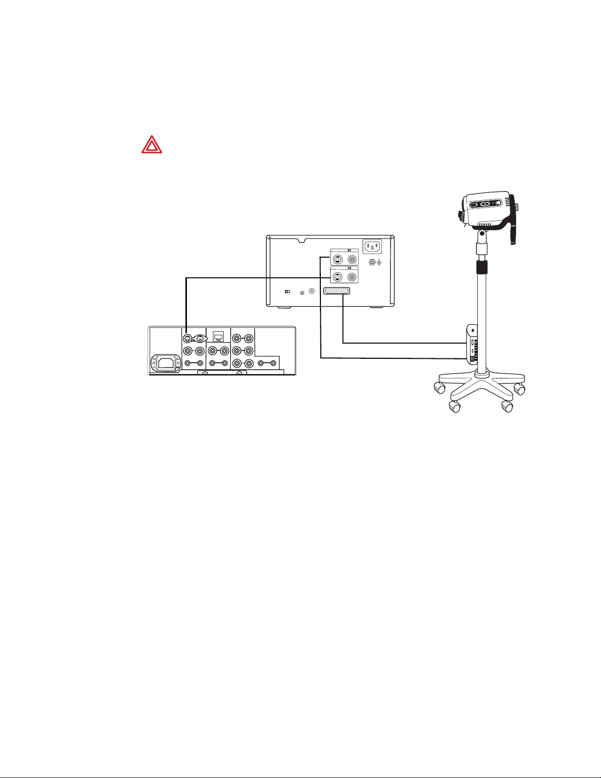
RS232 Interface Cable
S-Video Cable to
Printer S-Video In
S-Video Cable Out to Monitor
Line A S-Video (Y/C) In
Back Panel of Monitor
Back Panel of Printer
Connecting Video Colposcope with Optional VCR/
Video Printer
WARNING If peripheral devices (example: monitor, video printer, VCR ,other) do
not comply with IEC 60601-1-1, they must be kept out of the patient area (6 feet
minimum from patient).
Page 21

Directions for Use Connections and Assembly 19
Note
Assembly
General Precautions
Make sure the unit is always grounded and secure during use. Do not disable power cord
ground connection. Grounding reliability is achieved only when power cord is connected to
a hospital-grade receptacle. Inspect the electrical plug and cord routinely. Do not use if
damaged. Do not use the Video Colposcope in the presence of any flammable anesthetics.
Do not open the Video Colposcope housing. An electrical shock hazard exists due to high
voltage. There are no user serviceable parts inside the Video Colposcope, except the lamp.
Opening of the Video Colposcope housing by an unauthorized repair facility will
void the product warranty.
WARNING If peripheral devices (example: monitor, video printer, VCR ,other) do
not comply with IEC 60601-1-1, they must be kept out of the patient area (6 feet
minimum from patient).
WARNING DO NOT use a converter adapter that will convert the three-prong
AC plug to a two-prong line plug. The power supply in the Video Colposcope will
not be properly grounded and electric shock might result.
Video Colposcope
Before initial set up of the Video Colposcope, check all components received against the
parts list of components (see Components section of this manual) to verify a complete
set. If parts are missing, please notify Welch Allyn. Review the Nomenclature, Preparation
for Use, Operation, and Maintenance sections to become familiar with the equipment.
Caution The Video Colposcope is cooled via a vent fan located in the back of
the unit. The fan draws air in from beneath the Video Colposcope and exhausts
the air out the back of the Video Colposcope. To avoid overheating, verify that the
unit is no less than 6" from a wall.
Caution The colposcope can be damaged if the unit is transported while
holding the handle. The unit should be transported by grasping the pole.
Page 22
20 Connections and Assembly Welch Allyn Video Colposcope
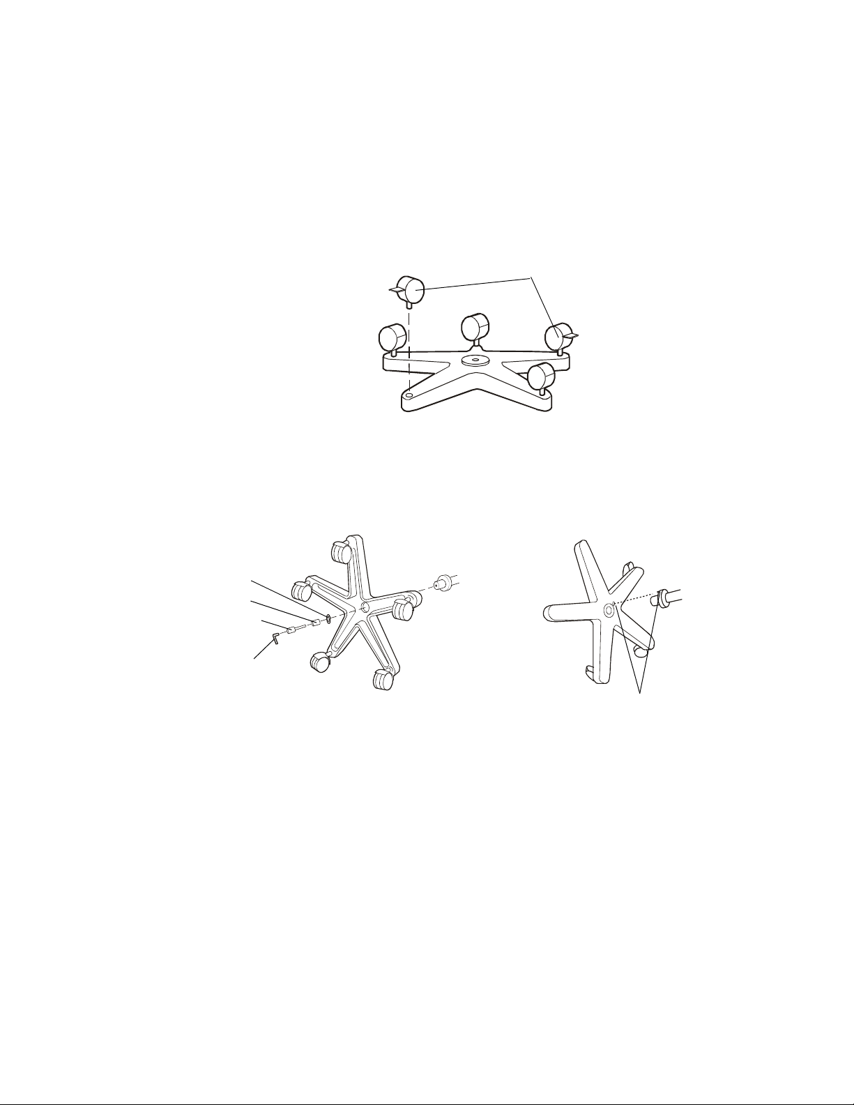
Locking caster
Allen Wrench
Hex Bolt
Spacer
Washer
Align pin with hole
Note
Vertical Stand Assembly
The Video Colposcope stand is shipped unassembled. Minimal assembly is required.
1. Remove the stand and base parts from their cartons.
2. Place base upside down on the floor and insert casters into holes on the bottom of
th
e base. (Do not place two locking casters next to each other.)
3. Place the base on the floor with casters down. Lock the two locking casters.
4. Place pole into the base, aligning the pin on the flange with the pin hole in the base.
Pl
ace bolt, spacer, and washer, oriented as shown, into the pole. Tighten securely
with the enclosed Allen wrench. (The assembly may need to be tilted.)
Before using the Video Colposcope, refer to “Setting Up Video Colposcope” section
of this manual.
Swing Arm Stand Assembly
The Video Colposcope stand is shipped unassembled. Minimal assembly is required.
BASE WEIGHS 58 LBS. YOU MAY REQUIRE ASSISTANCE TO LIFT IT.
1. To assemble the stand, remove the st
and and base parts from the cartons.
Page 23
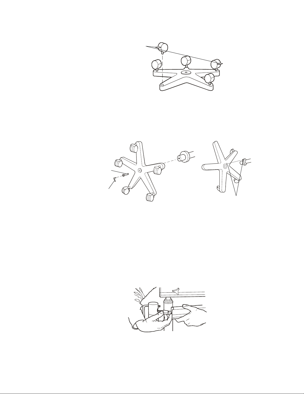
Locking caster
Directions for Use Connections and Assembly 21
Hex Bolt
Allen Wrench
Align pin with hole
2. Place base upside down on the floor and insert casters into holes on the bottom of
the base. (Do not place two locking casters next to each other.)
3. Place the base on the floor with casters down. Lock the two locking casters.
4. Place the vertical pole section of the assembly into the base, aligning the pin on the
lange with the pin hole in the base.
f
5. Locate the packaged bolt.
6. Place the bolt through the bottom of the pole. (The assembly may need to be tilted.)
7. Tighten securely with the enclosed Allen wrench.
8. Remove the bolt from the arm of the colposcope assembly and insert it through the
ho
le near the top of the pole.
9. Position the pole and the arm of the remaining colposcope assembly in close
ximity.
pro
10. Connect the two wire harnesses via their connectors. (T
his may require assistance for
proper assembly.)
.
11. Bring the colposcope swing arm assembly to the pole while at the same time pushing
the electrical connectors into the colposcope arm.
Page 24
22 Connections and Assembly Welch Allyn Video Colposcope
RS232 output
S-Video output
Power Cord
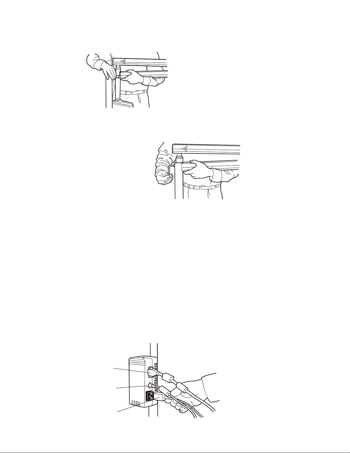
12. Tighten the bolt securely with the enclosed Allen wrench. Be sure not to pinch any of
the electrical wires between the vertical pole and arm of the colposcope assembly.
13. Before using the Video Colposcope, refer to Setting Up Video Colposcope section of
this manual.
Setting Up Video Colposcope
1. Connect the power cord to the power cord receptacle in the power supply located on
the Video Colposcope stand.
2. Plug the other end of the power cord into a properly grounded 110–120 volt AC outlet
(220–240 v
3. Connect the S-Video cable to the S-Video output on the side of the power supply
cated on the Video Colposcope stand.
lo
4. Connect the other end of the S-Video cable into the Line A connector S-Video (Y/C)
on the back of the monitor.
5. Plug the monitor into a properly grounded 110–120 volt AC outlet (220–240 volt,
50 cycle for international).
olt, 50 cycle for international).
Page 25

23
Note
4
Operation
Power Switch
With the power cord connected to a properly grounded outlet, and the S-video cable
connected to the Video Colposcope and monitor, activate the power switch on the handle
of the Video Colposcope.
Lamp Ignition
Once the Video Colposcope’s power switch has been activated, the lamp will ignite.
The lamp requires approximately 11 seconds to warm up.
Focus and Zoom Controls
Once the power switch has been activated, the Video Colposcope will execute a setup
procedure, ending in the low magnification setting, or 4.5x. To obtain coarse focus,
position the distal end of the Video Colposcope approximately 300 mm (12") from the
target. Adjust the Video Colposcope by moving the stand (for vertical stand), or the arm
(for the swing arm stand), until the picture is in focus. Press the + on one of the zoom
controls until maximum magnification is obtained, and readjust the position of the stand
or the swing arm until the picture is in focus. Fine focus, in either direction, is provided
by the focus controls once coarse focus has been achieved. After coarse focus is
achieved at maximum magnification, zoom control can be set to a desired lower
magnification by pressing either zoom control. Focus will be maintained throughout
the entire magnification range once these steps have been completed if the Video
Colposcope or target is not moved.
The setup (nominal) setting of the focus controls can be recovered by pressing
one of the zoom + controls for 4 seconds after maximum magnification has been
achieved.
Page 26

24 Operation Welch Allyn Video Colposcope
Note
Mag Index Control
Pressing the scan button on the monitor or activating this menu option sets the
display size to -3% “under” image scan size and alters the size of the image on
the screen, making the magnification index displayed inaccurate. Activating the
button or mem option briefly displays the word “under” on the monitor screen
and a red light displays on the scan button. To change the scan size back to
normal, press the scan button again and the word “over” briefly appears on the
monitor screen. This is the normal setting.
Activate the magnification index button by pressing the blue button located on the
right side of the colposcope (See “Side Views” on page 12.). The Mag Index refers to
magnification relative to a 14" monitor. Deactivate the magnification index by pressing
the mag index control again.
To determine the magnification*, multiply the mag index by the number in the table
below.
DISPLAY DEVICE Sony 14" Monitor, model
LMD1410
NUMBER BY WHICH TO MULTIPLY MAG INDEX 1.0
EXAMPLE: Mag. Index on screen 5
EXAMPLE: Magnification 5
*Magnification is the approximate size of an object displayed on a display device (monitor,
video print, etc.) divided by the actual size of the object.
Green Filter Control
Press the green filter button on the left side of the video colposcope (Figure on page 12)
to activate the electronic green filter. Press the green filter button again to deactive the
filter.
Polarization Filter Control
The Polarization Filter control can be rotated to reduce glare from the image as desired.
The filter is completely engaged (minimum glare) when the control is fully rotated to the
left. The filter can be disengaged by returning the Polarization Filter control to the full right
hand position.
Illumination Beam Director
The illumination beam director can be rotated up to 45° clockwise or counterclockwise to
better illuminate the examination area. To rotate the director, grasp the flat sides and twist
in either direction as desired. The illumination beam director moves with some resistance.
This helps to hold it securely in the desired position. The center position can be recovered
by returning the director to the detent position.
Page 27

Directions for Use Operation 25
Vertical Height Adjustment Ring (Vertical Colposcope Model Only)
The height of the vertical stand can be adjusted by rotating the black height adjustment
ring, located on the pole of the stand, counterclockwise. Once the ring has been
loosened, adjust the pole to the desired height and then tighten the ring again by rotating
it clockwise.
Swing Arm Height Adjustment (Swing Arm Colposcope Model Only)
Adjust the height of the swing arm stand by loosening the height adjustment knob
located on the arm of the stand. The swing arm can then be moved to the desired
position. After moving the arm, tighten knob securely by rotating clockwise. The desired
drag can be obtained by adjusting this knob either clockwise or counterclockwise.
Positioning Video Colposcope
The video colposcope can be angled up and down and left and right. To change the up/
down tilt angle, loosen the knob located on the tilt axis. The video colposcope can then
be tilted as necessary. To change the horizontal angle, loosen the knob located on the
support shaft. The drag of either knob can be set by loosening or tightening as necessary.
Remote Video Functions
The handle of the video colposcope contains three buttons that control three video
functions. These functions, provided by a remote video printer or Welch Allyn software
program, are Freeze, Print, and Toggle. (See “Operation” on page 23. of this manual for
connecting the printer to the video colposcope.)
• Pressing the freeze (“F”) button stores a new image in memory. The frozen image
is
displayed on the monitor or PC.
• Pressing the copy (“C”) button prints/saves the image displayed on the monitor.
If
live video is displayed, the image visible when the button was pressed will be
printed/saved.
• Pressing the video (“V”) button changes the display from printer memory (frozen
image) to live video, or from live video to printer memory (frozen image), depending
on the current mode.
Page 28

26 Operation Welch Allyn Video Colposcope
Page 29

27
Note
5
Maintenance
Disinfecting Solutions
The disinfecting solutions listed below are safe for cleaning the housing of the video
colposcope if used according to the manufacturer’s instructions for cleaning and
disinfecting, and in accordance with procedures detailed in the cleaning section of this
manual.
• 70% isopropyl alcohol
• 10% mild bleach solution
• 10% Wescodyne
References to brand names are not endorsements of their efficacy as disinfecting
solutions. However, tests have shown these solutions to be compatible with
Welch Allyn colposcopes, providing the manufacturers’ directions are followed.
Video Colposcope Cleaning
Turn the power switch off and unplug the power cord from the electrical outlet prior to
cleaning.
The video colposcope housing can be wiped down with a cloth dampened slightly with a
mild solution of disinfectant. Be careful not to allow the plug prongs to get wet. Also be
careful not to allow the camera lens or lamp lens to get wet.
Lens Cleaning
Camera Lens
Clean the camera lens with isopropyl alcohol or any commercial lens cleaner.
Caution Do not sterilize.
Caution Do not spray or allow solution to drip into the air vents.
Caution Do not immerse any part of the unit in cleaning solutions.
Page 30
28 Maintenance Welch Allyn Video Colposcope
Illumination Beam Director Lens
Caution DO NOT clean illumination beam director lens with alcohol. DO NOT
touch the camera or illumination lenses except as described in Maintenance
section of this manual.
Clean the illumiantion beam director lens with a cloth dampened slightly with warm water
and mild detergent.
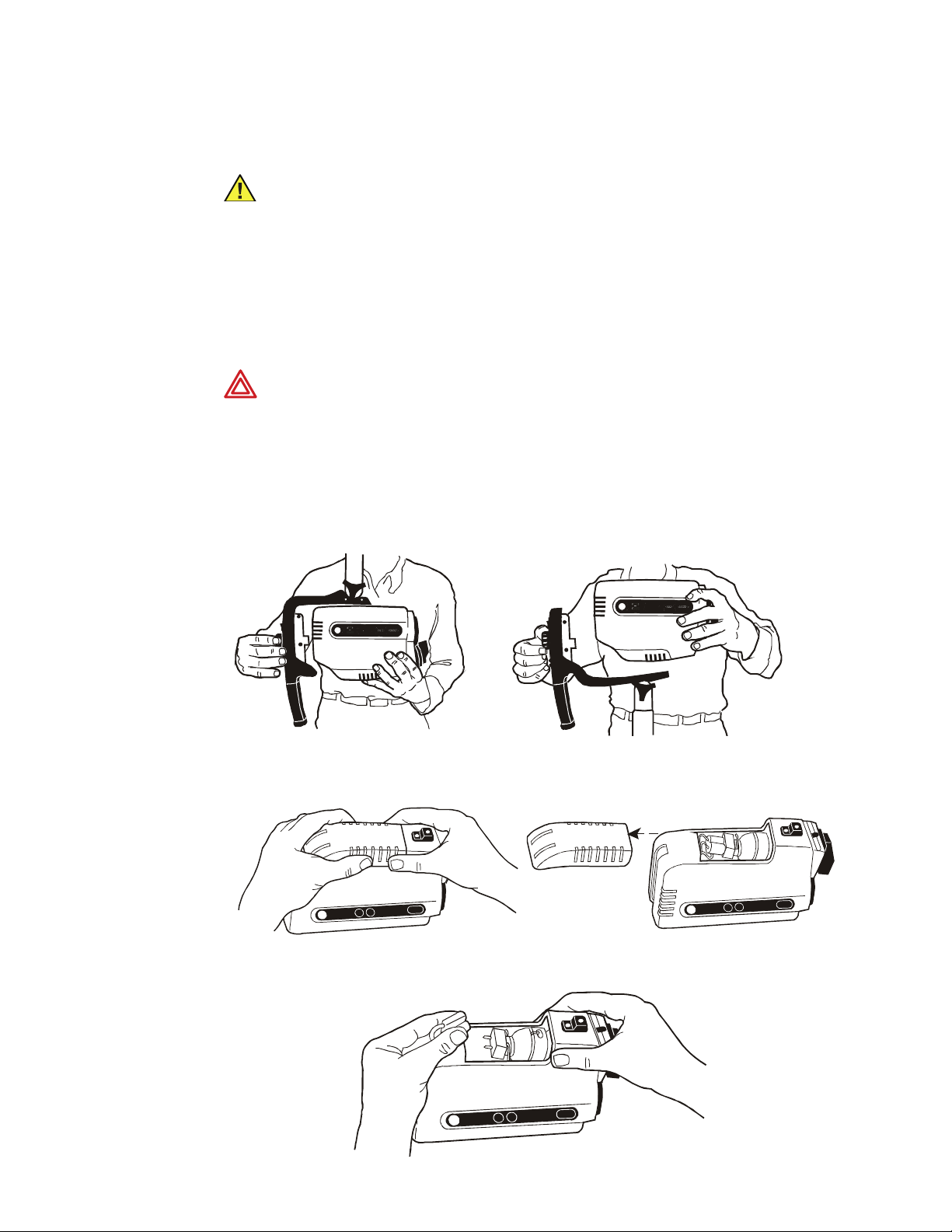
Replacing Lamp
WARNING The lamp operates at a high temperature. DO NOT attempt to
remove the lamp before allowing it to cool. Allow at least five minutes for the
lamp to cool before replacing. Replace with Welch Allyn lamp #09800-U only.
1. Turn the power switch off and unplug the power cord from the electrical outlet.
2. Holding the video colposcope as shown, turn the knob located at the back of the
ha
ndle counterclockwise and unscrew and remove the video colposcope from the
handle.
3. Place the unit on a suitable work surface. Slide the lamp access door away from the
housing as shown until the door is completely removed.
4. Unplug the lamp from the electrical connector.
Page 31

Directions for Use Maintenance 29
5. Push the retainer spring toward the back ofthe colposcope and remove the lamp from
its housing.
6. Remove a Welch Allyn replacement lamp # 09800-U from its package. Do not touch
the lamp itself or the interior reflective surface of the lamp. Skin oils will cause
premature lamp failure. Hold lamp by the outside of the reflector or the connector
only. Remove any grease or fingerprints with a clean cotton swab moistened with
alcohol. Do not leave any lint on the lamp.
7. Holding the retainer
spring as in Step 5, slide the new lamp into the lamp housing so
that the lamp’s alignment pin engages the alignment slot in the lamp holder. (Make
sure lamp is
properly seated and snaps into place.)
8. Plug the electrical connector onto the new lamp.
9. Slide the lamp access door securely back into place, reversing the process described
in Step 3 above.
10. Place the video colposcope back into the han
dle, making sure the power connector is
engaged.
11. Rotate the knob clockwise until snug.
12. Plug the power cord back into the electrical outlet.
Page 32

30 Maintenance Welch Allyn Video Colposcope
Ta b
Replacing Fuses
Two fuses are located in slots adjacent to the power supply cord receptacle on the side
of the power supply housing. This housing is attached to the pole of the video colposcope
stand.
1. To replace a blown fuse, remove the fuse holder b
holder out of the power supply.
2. Pull out and remove the blown fuse from the fuse holder.
y pressing the tab and pulling the
3. Replace with new fuses # T1.00L-250V 1A Time lag/Low Breaking Capacity
(Welch Allyn Part # 488307-9).
4. Reinsert the fuse holder by pressing until it snaps into place.
Page 33

Directions for Use Maintenance 31
Troubleshooting
Condition Check Action
Power does not come on. Power Cord
Check connections at power supply and
wall outlet.
Attachment of unit to handle
Attachment of unit to handle and door
to unit
Fuses
Wall outlet
No image on monitor. Monitor/other peripheral devices
Cable connections
Monitor input selection
Lamp will not light. Lamp housing
Lamp
Lamp access door
Printer does not
respond properly to
handle buttons.
Power cord and printer
Check colposcope unit’s alignment with
handle.
Make sure lamp access door and handle
are properly attached.
Remove fuse panel & replace blown fuse
with T1.00L 250V 1A time lag (Welch Allyn
part number # 488307-9).
Plug the power cord into a wall outlet
known to work.
Make sure power is on for all devices.
Make sure all video cables are connected
properly.
Make sure correct input selection is made
on the front panel.
Make sure lamp assembly is installed
properly.
Replace lamp.
Make sure lamp access door is properly
closed.
Unplug power cord from wall outlet, then
plug cord back in to outlet. At the same
time, turn printer off and then on again.
Printer
Make sure printer is on and is properly
connected.
Page 34

32 Maintenance Welch Allyn Video Colposcope
Page 35

33
6
Specifications
Video Colposcope
Item Specification Technical Data
Power requirements Voltage
Dimensions Vertical Stand
Weight Colposcope
Frequency
Current
Swing arm stand
Optical centerline to swing arm bottom
Colposcope HxWxD (excluding handles)
115VAC domestic
220–240VAC international
50/60Hz
1.0 Amp
Low: 36.0", high: 46.0"
(91.4 cm to 116.8 cm)
Low: 29.5", high: 49.5"
(74.9 cm to 125.7 cm)
15.0" (38.1 cm)
8.25" x 5.75" x 3.37"
(21.0 cm x 14.6 cm x 8.6 cm)
3.1 lbs (1.4 kg)
Vertical Stand
Swing arm stand
Video Colposcope
Specifications
Operating environment Ambient temperature
Illumination Lamp type
Cooling method Forced air via fan
Focal length
Magnification (relative to a 14" monitor)
Field of view
Depth of field
Relative humidity
Atmospheric pressure
Lamp life
Brightness adjustment
Lamp
Lamp voltage
25 lbs (11.3 kg)
80 lbs (36.3 kg)
300 mm (12")
4.5x – 30x (typ.)
66 mm – 14 mm
112 mm – 5 mm
50° F (+10° C) to 104°F (+40° C)
95% max
70kPa to 110kPa
21 Watt metal halide arc
750 hrs @ 1 hr per start
Automatic electronic shutter
Welch Allyn part no. 09800-U
60 volts
Page 36

34 Specifications Welch Allyn Video Colposcope
Item Specification Technical Data
Color system Color mosaic CCD
Video output S-Video (Y/C)
Remote Control RS-232 9-Pin D Female Connector
Transport/Storage
environment
Fuses T1.00L-250V
Classification Electro medical equipment FDA Class I equipment
Patents This product is covered by the following patents:
Ambient temperature
Relative humidity
(Welch Allyn part # 488307-9)
5,083,059; 5,117,154; 5,138,228; 5,144,201; 5,291,100; D391,360, D395,084; 5,840,012;
5,879,286; D416,088; 6,068,593; 6,147,705.
Patents pending
-40°F (-40°C) to 120° F (+50° C)
95% max.
1 Amp time lag,
low breaking capacity
Video Monitor
Item Specification Technical Data
Color Video Monitor
–minimum specifications
Color Video Monitor
–regulatory compliance
Resolution
Video Interface
User Controls
Display Aspect Ratio
Product safety
Electromagnetic compatibility (EMC)
640 x 480 pixels or greater
S-video input
Color, brightness, contrast
4:3
Conformance to local requirements,
examples: UL 6500; CE 60065; IEC 60065;
CAN/CSA E60065-00; other.
Conformance to local requirements,
examples: USA FCC Part 15; Canada
ICES-003; CE EN55103-1 & EN55013-2;
Japan VCCI; AS/NZS CISPR22; other.
Page 37

Directions For Use Specifications 35
EC REP
Agency Approvals
Conforms to: UL 2601-1
Certified to: CAN/CSA C22.2 No. 601.1-M90
IEC 601-1
EN60601-1
EN/IEC 60601-1-2
The CE mark on this product indicates it has been tested to and conforms with the
provisions noted in the 93/42/EEC Medical Device Directive.
Authorized EC Representative:
European Regulatory Manager
Welch Allyn, Ltd.
Navan Business Park
Dublin Road
Navan, County Meath, Republic of Ireland
Tel +353 46 90 67700
Fax +353 46 90 67756
Page 38

36 Specifications Welch Allyn Video Colposcope
Guidance and Manufacturer’s Declaration
Emissions and Immunity Information
Electromagnetic Emissions
The REF 880 and 890 Series Video Colposcope is intended for use in the electromagnetic environment specified below. The customer
the REF 880 and 890 Series Video Colposcope should assure that it is used in such an environment.
Emissions Test Compliance Electromagnetic Environment – Guidance
RF emissions
CISPR 11
RF emissions
CISPR 11
Harmonic emissions
IEC 61000-3-2
Voltage fluctuations/
flic
ker emissions
IEC 61000-3-3
Group 1 The REF 880 and 890 Series Video Colposcope uses RF energy only for its internal
unction. Therefore, its RF emissions are very low and are not likely to cause any
f
interference in nearby electronic equipment.
Class B The REF 880 and 890 Series Video Colposcope is suitable for use in all establishments,
inc
luding domestic establishments and those directly connected to the public
low-voltage power supply network that supplies buildings used for domestic purposes.
Class A
Complies
or user of
Page 39

Directions For Use Specifications 37
Electromagnetic Immunity
The REF 880 and 890 Series Video Colposcope is intended for use in the electromagnetic environment specified below. The customer or user of
the REF 880 and 890 Series Video Colposcope should assure that it is used in such an environment.
Immunity Test IEC 60601
Test Level
Electrostatic discharge
(ESD)
IEC 61000-4-2
Electrical fast transient/
burst
IEC 61000-4-4
Surge
IEC 61000-4-5
Voltage dips, short
interruptions, and
voltage variations on
power supply input
lines.
IEC 61000-4-11
Power frequency
(50/60Hz)
magnetic field
± 6 kV contact
± 8 kV air
±2 kV for power supply
lines
±1 kV for input/output
lines
±1 kV differential mode
±2 kV common mode
>95% dip in 0.5 cycle
60% dip in 5 cycles
30% dip for 25 cycles
>95% dip in 5 seconds
3 A/m 3 A/m Power frequency magnetic fields should be at levels
Compliance Level Electromagnetic Environment – Guidance
± 6 kV contact
± 8 kV air
±2 kV for power supply
lines
±1 kV for input/output
lines
±1 kV differential mode
±2 kV common mode
>95% dip in 0.5 cycle
60% dip in 5 cycles
30% dip for 25 cycles
>95% dip in 5 seconds
Floors should be wood, concrete, or ceramic tile. If floors are
covered with synthetic material, the relative humidity should
be at least 30%.
Mains power quality should be that of a typical commercial or
hospital environment.
Mains power quality should be that of a typical commercial or
hospital environment.
Mains power quality should be that of a typical commercial or
hospital environment. If the user of the REF 880 and 890
Series Video Colposcope requires continued operation during
power mains interruptions, it is recommended that the REF
880 and 890 Series Video Colposcope be powered from an
uninterruptible power supply or battery.
characteristic of a typical location in a typical commercial or
hospital environment.
IEC 61000-4-8
Page 40

38 Specifications Welch Allyn Video Colposcope
PPP
Electromagnetic Immunity
The REF 880 and 890 Series Video Colposcope is intended for use in the electromagnetic environment specified below. The customer or user of
the REF 880 and 890 Series Video Colposcope should assure that it is used in such an environment.
Immunity Test IEC 60601
Test Level
Conducted RF
IEC 61000-4-6
Radiated RF
IEC 61000-4-3
3 Vrms
150 kHz to 80 MHz
3 V/m
80 MHz to 2.5 GHz
Compliance
Electromagnetic Environment – Guidance
Level
Portable and mobile RF communications equipment should be used no
closer to any part of the Video Colposcope, including cables, than the
recommended separation distance calculated from the equation applicable
to the frequency of the transmitter.
Recommended separation distance
3 Vrms d = (1.17)
3 V/m d = (1.17) 80 MHz to 800 MHz
d = (2.33) 800 MHz to 2.5 GHz
where P is the maximum output power rating of the transmitter in watts (W)
according to the transmitter manufacturer and d is the recommended
separation distance in metres (m).
Field strengths from fixed RF transmitters, as determined by an
electromagnetic site survey,
in each frequency range.
a
should be less than the compliance level
b
Interference may occur in the vicinity of equipment marked with the
following symbol:
Note 1: At 80 MHz and 800 MHz, the higher frequency range applies.
Note 2: These guidelines may not apply in all situations. Electromagnetic propagation is affected by absorption and reflection from structures,
objects, and people.
a
Field strengths from fixed transmitters, such as base stations for radio (cellular/cordless) telephones and land mobile radios, amateur radio,
AM and FM radio broadcast and TV broadcast cannot be predicted theoretically with accuracy. To assess the electromagnetic environment due
to fixed RF transmitters, an electromagnetic site survey should be considered. If the measured field strength in the location in which the REF
880 and 890 Series Video Colposcope is used exceeds the applicable RF compliance level above, the Video Colposcope should be observed to
verify normal operation. If abnormal performance is observed, additional measures may be necessary, such as reorienting or relocating the
Video Colposcope.
b
Over the frequency range 150 kHz to 80 MHz, field strengths should be less than 3 V/m.
Page 41

Directions For Use Specifications 39
PPP
Recommended Separation Distances Between Portable and Mobile RF Communications Equipment and the Video Colposcope
The REF 880 and 890 Series Video Colposcope is intended for use in an electromagnetic environment in which radiated RF disturbances are
controlled. The customer or user of the REF 880 and 890 Series Video Colposcope can help prevent electromagnetic interference by maintaining
a minimum distance between portable and mobile RF communications equipment (transmitters) and the REF 880 and 890 Series Video
Colposcope as recommended below, according to the maximum output power of the communications equipment.
Separation Distance According to Frequency of Transmitter (m)
Rated Max. Output
Power of Transmitter
(W)
0.01 0.11667 0.11667 0.23333
0.1 0.36894 0.36894 0.73785
1 1.1667 1.1667 2.3333
10 3.6894 3.6894 7.3785
100 11.667 11.667 23.3333
For transmitters rated at a maximum output power not listed above, the recommended separation distance d in meters (m) can be estimated
using the equation applicable to the frequency of the transmitter, where P is the maximum output power rating of the transmitter in watts (W)
according to the transmitter manufacturer.
Note 1: At 80 MHz and 800 MHz, the separation distance for the higher frequency range applies.
Note 2: These guidelines may not apply in all situations. Electromagnetic propagation is affected by absorption and reflection from structures,
objects, and people.
150 kHz to 80 MHz
d = (1.17)
80 MHz to 800 MHz
d = (1.17)
800 MHz to 2.5 GHz
d = (2.33)
Page 42

40 Specifications Welch Allyn Video Colposcope
Page 43

41
7
Service
Caution Unauthorized repairs will void the warranty.
A Welch Allyn Service Center must perform all repairs on products under warranty.
Qualified electronics personnel or a Welch Allyn Service Center should repair products
out of warranty.
Technical Assistance
If you have an equipment problem that you cannot resolve call the Welch Allyn Technical
Support center nearest you (page 2) on normal business days.
If you are advised to return a product to Welch Allyn for repair or routine maintenance,
schedule the repair with the service center nearest you. The part and serial numbers are
located on the housing of the colposcope near the fan. Remove the colposcope from the
handle to locate these numbers
Before returning a product for repair, you must obtain authorization from Welch Allyn.
Service personnel will give you a Service Notification number. Please note this number
on the outside of your shipping box. Returns without a Service Notification number will
not be accepted for delivery.
Service Manual/Spare Parts
The Service Manual is a comprehensive guide to troubleshooting, service, and repair
available by request to qualified electronics personnel.
Also included with the Service Manual is a complete spare parts list. Order spare parts
from your local Welch Allyn Service Center.
Page 44

42 Service Welch Allyn Video Colposcope
Page 45

Warranty
Welch Allyn warrants Video Colposcope, when new, to be free of defects in material
and workmanship and to perform in accordance with manufacturer’s specifications
for a period of one year from the date of purchase from Welch Allyn or its authorized
distributors or agents. Welch Allyn will either repair or replace any components found to
be defective or at variance from manufacturer’s specifications within this time at no cost
to the customer. It shall be the purchaser’s responsibility to return Video Colposcope to
Welch Allyn or an authorized distributor, agent, or service representative. This warranty
does not include the lamp, breakage or failure due to tampering, misuse, neglect,
accidents, modification, or shipping. This warranty is also void if the instrument is not
used in accordance with manufacturer’s recommendations or if repaired by other than
Welch Allyn or an authorized agent. Purchase date determines warranty requirements.
No other express warranty is given.
43
Remember to submit the instrument registration/warranty card for warranty validation.
Complete the information and mail the pre-addressed card to Welch Allyn.
Page 46

44 Warranty Welch Allyn Video Colposcope
Page 47

Colposcope vidéo
Mode d’emploi
RÉF 88000A/88001A/89000A/88007/89001A/88007/88002A/88004A/88006A/89006A
Page 48

46 Welch Allyn Colposcope vidéo
Copyright 2005 Welch Allyn. Tous droits réservés. Nul n’est autorisé à reproduire ou à copier, sous
quelque forme que ce soit, tout ou partie de ce manuel sans autorisation préalable de Welch Allyn.
Welch Allyn décline toute responsabilité pour les dommages corporels subis par quiconque ou pour les
usages illicites ou impropres pouvant entraîner une incapacité à utiliser ce produit conformément aux
instructions, précautions, avertissements ou indications d’utilisation inclus dans ce manuel.
Welch Allyn
®
est une marque déposée de Welch Allyn.
Pour plus d’informations sur les produits Welch Allyn, contacter l’Assistance technique Welch Allyn :
Etats-Unis +1 315 685 4560
+1 800 535 6663
Allemagne +49 7477 9271 70 Australie +61 2 9638 3000
Amérique latine +1 305 669 9003 Chine +86 21 6327 9631
Canada +1 800 561 8797 France +33 1 60 09 33 66
Centre d’appels en Europe +353 46 90 67790 Japon +81 3 3219 0071
Royaume-Uni +44 207 365 6780 Pays-Bas +31 157 505 000
Singapour 65 6419 8100 Suède +46 85 853 6551
Afrique du Sud +27 11 777 7555
Référence du manuel 880332 Vér C
Welch Allyn
4341 State Street Road
Skaneateles Falls, NY 13153 États-Unis
www.welchallyn.com
Imprimé aux États-Unis
Page 49

Table des Matières
1 - Introduction . . . . . . . . . . . . . . . . . . . . . . . . . . . . . . . . . . . . . . . . . . . . 49
Indications. . . . . . . . . . . . . . . . . . . . . . . . . . . . . . . . . . . . . . . . . . . . . . . . . . . . . . 49
Symboles . . . . . . . . . . . . . . . . . . . . . . . . . . . . . . . . . . . . . . . . . . . . . . . . . . . . . . 49
Avertissements et précautions . . . . . . . . . . . . . . . . . . . . . . . . . . . . . . . . . . . . . . 50
Avertissements . . . . . . . . . . . . . . . . . . . . . . . . . . . . . . . . . . . . . . . . . . . . . . 50
Précautions. . . . . . . . . . . . . . . . . . . . . . . . . . . . . . . . . . . . . . . . . . . . . . . . . . 51
2 - Composants. . . . . . . . . . . . . . . . . . . . . . . . . . . . . . . . . . . . . . . . . . . . 53
Colposcope vidéo . . . . . . . . . . . . . . . . . . . . . . . . . . . . . . . . . . . . . . . . . . . . . . . . 53
Vue de face. . . . . . . . . . . . . . . . . . . . . . . . . . . . . . . . . . . . . . . . . . . . . . . . . . . . . 55
Vues latérales . . . . . . . . . . . . . . . . . . . . . . . . . . . . . . . . . . . . . . . . . . . . . . . . . . . 56
Vue arrière . . . . . . . . . . . . . . . . . . . . . . . . . . . . . . . . . . . . . . . . . . . . . . . . . . . . . 57
Vue de dessous . . . . . . . . . . . . . . . . . . . . . . . . . . . . . . . . . . . . . . . . . . . . . . . . . 57
Support vertical. . . . . . . . . . . . . . . . . . . . . . . . . . . . . . . . . . . . . . . . . . . . . . . . . . 58
Bras pivotant. . . . . . . . . . . . . . . . . . . . . . . . . . . . . . . . . . . . . . . . . . . . . . . . . . . . 58
Moniteur . . . . . . . . . . . . . . . . . . . . . . . . . . . . . . . . . . . . . . . . . . . . . . . . . . . . . . . 59
Imprimante . . . . . . . . . . . . . . . . . . . . . . . . . . . . . . . . . . . . . . . . . . . . . . . . . . . . . 60
47
3 - Connexions et montage . . . . . . . . . . . . . . . . . . . . . . . . . . . . . . . . . . 61
Connexion du Colposcope vidéo avec le moniteur . . . . . . . . . . . . . . . . . . . . . . . 61
Connexion du Colposcope vidéo avec un magnétoscope/une imprimante
vidéo optionnels . . . . . . . . . . . . . . . . . . . . . . . . . . . . . . . . . . . . . . . . . . . . . . . . . 62
Montage . . . . . . . . . . . . . . . . . . . . . . . . . . . . . . . . . . . . . . . . . . . . . . . . . . . . . . . 63
Précautions générales . . . . . . . . . . . . . . . . . . . . . . . . . . . . . . . . . . . . . . . . . 63
Colposcope vidéo. . . . . . . . . . . . . . . . . . . . . . . . . . . . . . . . . . . . . . . . . . . . . 63
Montage du support vertical . . . . . . . . . . . . . . . . . . . . . . . . . . . . . . . . . . . . 64
Montage du bras pivotant . . . . . . . . . . . . . . . . . . . . . . . . . . . . . . . . . . . . . . 64
Configuration du Colposcope vidéo . . . . . . . . . . . . . . . . . . . . . . . . . . . . . . . 66
4 - Fonctionnement . . . . . . . . . . . . . . . . . . . . . . . . . . . . . . . . . . . . . . . . 67
Commutateur de mise sous tension . . . . . . . . . . . . . . . . . . . . . . . . . . . . . . . . . 67
Allumage de la lampe . . . . . . . . . . . . . . . . . . . . . . . . . . . . . . . . . . . . . . . . . . . . . 67
Commandes de focalisation et du zoom (Focus et Zoom) . . . . . . . . . . . . . . . . . 67
Commande de l’indice de grossissement « Mag Index » . . . . . . . . . . . . . . . . . 68
Commande du filtre vert. . . . . . . . . . . . . . . . . . . . . . . . . . . . . . . . . . . . . . . . . . . 68
Bouton de contrôle du filtre polarisant . . . . . . . . . . . . . . . . . . . . . . . . . . . . . . . . 68
Directeur du faisceau d’illumination . . . . . . . . . . . . . . . . . . . . . . . . . . . . . . . . . . 68
Bague de réglage de la hauteur verticale
(modèle de colposcope vertical uniquement) . . . . . . . . . . . . . . . . . . . . . . . . . . . 69
Page 50

48 Table des Matières Welch Allyn Colposcope vidéo
Réglage de la hauteur du bras pivotant
(modèle de colposcope à bras pivotant uniquement) . . . . . . . . . . . . . . . . . . . . . 69
Positionnement du colposcope vidéo. . . . . . . . . . . . . . . . . . . . . . . . . . . . . . . . . 69
Fonctions vidéos à distance . . . . . . . . . . . . . . . . . . . . . . . . . . . . . . . . . . . . . . . . 69
5 - Entretien. . . . . . . . . . . . . . . . . . . . . . . . . . . . . . . . . . . . . . . . . . . . . . . 71
Solutions désinfectantes . . . . . . . . . . . . . . . . . . . . . . . . . . . . . . . . . . . . . . . . . . 71
Nettoyage du colposcope vidéo . . . . . . . . . . . . . . . . . . . . . . . . . . . . . . . . . . . . . 71
Nettoyage des lentilles . . . . . . . . . . . . . . . . . . . . . . . . . . . . . . . . . . . . . . . . . . . . 71
Lentille de la caméra . . . . . . . . . . . . . . . . . . . . . . . . . . . . . . . . . . . . . . . . . . 71
Lentille du directeur du faisceau d’illumination . . . . . . . . . . . . . . . . . . . . . . 72
Remplacement de la lampe . . . . . . . . . . . . . . . . . . . . . . . . . . . . . . . . . . . . . . . . 72
Remplacement des fusibles . . . . . . . . . . . . . . . . . . . . . . . . . . . . . . . . . . . . . . . . 74
Dépannage . . . . . . . . . . . . . . . . . . . . . . . . . . . . . . . . . . . . . . . . . . . . . . . . . . . . . 75
6 - Caractéristiques. . . . . . . . . . . . . . . . . . . . . . . . . . . . . . . . . . . . . . . . . 77
Colposcope vidéo . . . . . . . . . . . . . . . . . . . . . . . . . . . . . . . . . . . . . . . . . . . . . . . . 77
Moniteur vidéo . . . . . . . . . . . . . . . . . . . . . . . . . . . . . . . . . . . . . . . . . . . . . . . . . . 78
Approbations agence . . . . . . . . . . . . . . . . . . . . . . . . . . . . . . . . . . . . . . . . . . . . . 79
Assistance et déclaration du fabricant . . . . . . . . . . . . . . . . . . . . . . . . . . . . . . . . 80
Informations relatives aux émissions et à l’immunité . . . . . . . . . . . . . . . . . 80
7 - Entretien. . . . . . . . . . . . . . . . . . . . . . . . . . . . . . . . . . . . . . . . . . . . . . . 85
Assistance technique . . . . . . . . . . . . . . . . . . . . . . . . . . . . . . . . . . . . . . . . . . 85
Manuel d’entretien/Pièces détachées . . . . . . . . . . . . . . . . . . . . . . . . . . . . . 85
Garantie . . . . . . . . . . . . . . . . . . . . . . . . . . . . . . . . . . . . . . . . . . . . . . . . . 87
Page 51

49
1
Introduction
Nous vous remercions d’avoir fait l’acquisition du Colposcope vidéo Welch Allyn. Suivre
les instructions de fonctionnement et d’entretien contenues dans ce manuel pour assurer
le fonctionnement fiable de votre Colposcope vidéo pendant de nombreuses années.
Lire intégralement ces instructions avant d’utiliser votre nouveau Colposcope vidéo.
IMPORTANT : Avant de faire fonctionner l’équipement, lire et assimiler les informations
contenues dans ce manuel.
Indications
Examen des tissus du vagin, du col de l’utérus et des organes génitaux externes, afin de
rechercher, par le biais du grossissement, une cytologie anormale du col utérin ou des
lésions suspectes des voies génitales féminines inférieures. Utilisé également dans le
cadre de biopsies et de traitements jugés nécessaires.
Symboles
Sous tension : Alimentation :
branchement à l’alimentation
basse tension.
Hors tension : Alimentation :
débranchement de l’alimentation
basse tension.
Précaution : Consulter le
manuel d’utilisation pour des
informations supplémentaires.
Hautes températures Attention : Dans ce manuel, Attention
Risque d’incendie. Remplacer
les fusibles comme indiqué.
L’unité est alimentée dès que le
cordon d’alimentation est
branché.
Avertissement : Les avertissements
de ce manuel identifient les conditions
ou pratiques qui, si elles ne sont pas
corrigées ou arrêtées immédiatement,
risquent de provoquer des blessures,
des maladies ou le décès du patient.
identifie les conditions ou pratiques
qui, si elles ne sont pas corrigées ou
arrêtées immédiatement, risquent de
provoquer des pertes de données, un
endommagement ou une défaillance
du matériel.
Lumière à haute intensité
Équipement de type B
Page 52

50 Introduction Welch Allyn Colposcope vidéo
Avertissements et précautions
Familiariser tout le personnel utilisant cet équipement avec les informations globales de
sécurité contenues dans ce résumé. Ce manuel comprend également des avertissements
et précautions spécifiques.
Avertissements
Les avertissements de ce manuel identifient les conditions ou pratiques qui, si elles ne
sont pas corrigées ou arrêtées immédiatement, risquent de provoquer des blessures,
des maladies ou le décès du patient.
AVERTISSEMENT Les utilisateurs de cet équipement doivent être totalement
formés aux procédures médicales appropriées. Ils devront en outre prendre le
temps de lire et d’assimiler ces instructions avant d’effectuer toute procédure.
Ils devront aussi lire et assimiler les instructions concernant tout autre équipement
utilisé en conjonction avec le Colposcope vidéo (par ex. des générateurs
électrochirurgicaux). Le non-respect de ces instructions peut provoquer des
blessures aux patientes et/ou des dommages au Colposcope vidéo.
AVERTISSEMENT Ne pas utiliser le Colposcope vidéo en présence de gaz ou de
produits chimiques inflammables ou explosifs (par exemple, des anesthésiques).
Ne pas l’installer dans des lieux où ces matériaux sont couramment utilisés.
AVERTISSEMENT Éloigner les liquides de l’équipement électrique pour éviter le
risque d’électrocution et de dommages à l’instrument.
AVERTISSEMENT La lampe est extrêmement brillante. NE PAS regarder
directement la lentille d’illumination quand la lampe est allumée.
AVERTISSEMENT L’utilisateur du Colposcope vidéo respectera les conditions de
fonctionnement indiquées dans ce manuel. Sinon, des dommages à l’instrument
peuvent en résulter et/ou la sécurité de la patiente/de l’opérateur risque d’être
compromise.
AVERTISSEMENT Tous les connecteurs d’entrée et de sortie (E/S) du signal
sont conçus pour être connectés uniquement à des périphériques (par exemple :
moniteur, imprimante vidéo, magnétoscope, PC, convertisseur DV) conformes à
la norme IEC 60601-1 (Règles générales de sécurité, appareils électromédicaux)
ou autres normes IEC (par exemple IEC 60950, matériels de traitement de
l’information – Sécurité) en fonction de la nature du périphérique. La connexion
d’autres périphériques au Colposcope vidéo peut augmenter le risque associé
au châssis ou aux courants de fuite de la patiente. Pour assurer la sécurité de
l’utilisateur et de la patiente, l’utilisateur doit prendre en considération les règles
relatives au courant de fuite du système de la norme IEC 60601-1-1 (Appareils
électromédicaux, Règles de sécurité relatives aux systèmes électromédicaux).
L’utilisateur doit mesurer les courants de fuite en conséquence pour confirmer
qu’il n’y a aucun risque d’électrocution. Un transformateur d’isolation conforme à
la norme IEC 60601-1 servant à alimenter les périphériques supplémentaires peut
être utilisé pour contrôler le courant de fuite du système afin de se conformer aux
règles de la norme IEC 60601-1-1.
AVERTISSEMENT Si des périphériques (par exemple : moniteur, imprimante
vidéo, magnétoscope, autres) ne sont pas conformes à IEC 60601-1-1 (Appareils
électromédicaux, Règles de sécurité pour les systèmes électromédicaux),
ils doivent être maintenus en-dehors de la zone de la patiente (à au moins
1 mètre 80 de la patiente).
Page 53

Mode d’emploi Introduction 51
AVERTISSEMENT NE PAS utiliser d’adaptateur transformateur qui convertira la
prise CA à trois broches en une prise secteur à deux broches. L’alimentation du
Colposcope vidéo ne sera pas correctement mise à la terre et une électrocution
pourrait en résulter.
AVERTISSEMENT Par mesure de sécurité, ne brancher le Colposcope vidéo
qu’à une prise 110-120 V c.a. (pays internationaux 220-240 V, 50 cycles) de qualité
hospitalière et mise à la terre.
AVERTISSEMENT La lampe fonctionne à haute température. NE PAS tenter de
l’enlever avant de l’avoir laissée refroidir. La laisser refroidir au moins cinq minutes
avant de la remplacer. La remplacer uniquement par une lampe Welch Allyn
nº 09800-U.
Précautions
Dans ce manuel, Attention identifie les conditions ou pratiques qui, si elles ne sont pas
corrigées ou arrêtées immédiatement, risquent de provoquer des pertes de données, un
endommagement ou une défaillance du matériel.
Attention La loi fédérale des États-Unis limite la vente de cet instrument à un
médecin ou à un autre professionnel de la santé agréé, ou à leur prescription.
Attention Examiner périodiquement le cordon d’alimentation pour s’assurer
qu’il ne présente aucun signe de coupure, d’abrasion ou d’éraflure.
Attention Ne jamais ranger ou utiliser le Colposcope vidéo dans des lieux où
il risquerait de se mouiller ou d’être exposé à des conditions environnementales
comme des températures ou une humidité extrêmes, la lumière directe du soleil,
la poussière, etc.
Attention Toutes réparations du Colposcope vidéo doivent être confiées à
Welch Allyn ou à un centre de réparation agréé.
Attention Aucune réparation ne peut être effectuée par l’utilisateur (sauf le
remplacement de la lampe et des fusibles) ni dans cette unité ni dans les
accessoires. Toute tentative d’ouvrir le boîtier ou de réparer l’unité annulera la
garantie.
Attention Le Colposcope vidéo est refroidi par un ventilateur situé à l’arrière de
l’unité. Ce ventilateur aspire l’air en-dessous du Colposcope vidéo et l’expulse à
l’arrière de ce dernier. Pour empêcher la surchauffe, ne pas le placer à moins de
15,20 cm d’un mur.
Attention Ne pas nettoyer la lentille d’illumination avec de l’alcool. Ne pas
toucher la lentille optique ni la lentille d’illumination, sauf comme décrit à la
section Entretien de ce manuel.
Attention Risque d’endommagement du colposcope s’il est transporté par la
poignée. L’appareil doit être transporté par la potence.
Attention Ne pas stériliser.
Attention Ne pas vaporiser ni laisser la solution goutter dans les évents.
Attention N’immerger aucune partie de l’appareil dans des solutions
nettoyantes.
Page 54

52 Introduction Welch Allyn Colposcope vidéo
Page 55

53
88000A
89000A
Colposcope vidéo et support vertical
avec visserie :
• Clé Allen
• Boulon Allen
• Rondelle de montage
•Entretoise
Colposcope vidéo et support à bras
pivotant avec visserie :
• Clé Allen
• Boulon
2
Composants
Colposcope vidéo
Page 56

54 Composants Welch Allyn Colposcope vidéo
Toutes les illustrations ne sont fournies qu’à titre de référence.
88600
Câble S-vidéo
761076-0
Cordon d’alimentation
Accessoires en option
09800-U
Lampe de rechange
88500
Câble d’interface RS-232
488307-9
Fusible de rechange (2 nécessaires)
88010
Modèle cervical
88040
Housse pour support vertical
89040
Housse pour bras pivotant
Page 57

Mode d’emploi Composants 55
Directeur du faisceau
d’illumination. Dirige le
faisceau de la lampe.
Lentille de la caméra. La lentille qui
établit le grossissement et le champ.
Lentille du directeur du
faisceau d’illumination.
Fournit de la lumière pour
l’examen.
Remarque
88030
Support vertical avec socle uniquement
89030
Support à bras pivotant avec socle uniquement
Moniteur. Pour plus de détails, voir « Moniteur vidéo »
page 78. Pour plus de renseignements, contacter
Welch Allyn.
Vue de face
Magnétoscope/Imprimante. Pour plus de
renseignements, contacter Welch Allyn.
Système de capture des images. Pour plus de
renseignements, contacter Welch Allyn.
Seuls les accessoires et les composants indiqués dans ce manuel doivent
être utilisés avec le système de Colposcope vidéo de Welch Allyn.
Page 58

56 Composants Welch Allyn Colposcope vidéo
FINE
FINE
MAG
INDEX
Bouton de contrôle du
zoom (Zoom). Appuyer sur
+ ou - pour augmenter ou
diminuer le grossissement.
Orifices de ventilation.
Laissent l’air entrer et sortir
de l’unité pour refroidir les
composants internes.
Voyant lumineux du filtre
vert. S’allume si le filtre vert
électronique est activé.
Orifices de ventilation. Laissent
l’air entrer et sortir de l’unité pour
refroidir les composants internes.
Bouton du filtre vert (Green
filter). Appuyer sur ce bouton
pour activer ou désactiver le
filtre vert électronique.
Bouton de contrôle de la
focalisation fine (Fine
Focus). Appuyer sur < ou >
règle la focalisation.
Bouton de contrôle du
zoom (Zoom). Appuyer sur
+ ou - pour augmenter ou
diminuer le grossissement.
Bouton de contrôle de la
focalisation fine (Fine Focus).
Appuyer sur < ou > règle la
focalisation.
Bouton de contrôle du
filtre polarisant. Règle
la brillance de l’image.
Bouton Mag. Affiche l’index
de grossissement à l’écran.
Voyant lumineux Mag. S’allume si
l’index de grossissement est activé.
Vues latérales
Page 59

Mode d’emploi Composants 57
F
C
V
Bouton de fixation. Fixe la
poignée au Colposcope vidéo.
Poignée du Colposcope vidéo.
Permet de placer le colposcope
dans la position haute/basse,
gauche/droite correcte.
Boutons de fonction vidéo
à distance. Permettent
l’utilisation des fonctions de
sauvegarde et d’impression à
distance avec l’accessoire
adapté.
Orifices de ventilation.
Laissent l’air entrer et sortir
de l’unité pour refroidir les
composants internes.
Commutateur marche/arrêt
Contrôle l’alimentation du
Colposcope vidéo.
Porte d’accès à la lampe. S’enlève pour permettre le
remplacement de la lampe. (Remarque : si la porte n’est pas
bien fermée, les commutateurs d’alimentation de
verrouillage ne s’activent pas et la lampe ne s’allume pas.)
Pièce de montage. Permet la fixation du Colposcope vidéo sur la
potence. Sur le modèle à bras pivotant, la pièce de montage est
située en haut du colposcope. Sur le modèle à support vertical,
elle se trouve en bas du colposcope.
Orifices de ventilation.
Laissent l’air entrer et sortir
de l’unité pour refroidir les
composants internes.
Vue arrière
Vue de dessous
Page 60

58 Composants Welch Allyn Colposcope vidéo
Support vertical à base
roulante. Permet la mobilité
grâce à sa base à 5 roulettes,
dont deux sont verrouillables.
Compartiment fusible.
S’ouvre pour permettre le
remplacement des fusibles.
Logement du cordon
d’alimentation. Se relie au cordon
d’alimentation, qui doit être branché
à une prise 110-120 V c.a. de qualité
hospitalière (pays internationaux
220-240 volts, 50 cycles).
Sortie S-vidéo. Sort S-Video.
Connecteur du câble
d’interface RS232. Se relie
au câble d’interface RS-232.
Bague de réglage de la hauteur.
Permet le déplacement vertical et le
verrouillage du support à la hauteur
désirée. Réglage de la hauteur verticale
: de 91,4 cm à 116,8 cm.
Bras pivotant à base roulante.
Permet le positionnement
supérieur de l’instrument grâce à
sa base pondérée à 5 roulettes,
dont deux sont verrouillables.
Hauteur verticale : 74,9 cm à
125,7 cm.
Molette de réglage de la
hauteur. Permet de régler la
tension du bras et la hauteur
verticale de 67,3 cm à 115,6 cm.
Support vertical
Bras pivotant
Page 61

Mode d’emploi Composants 59
LINE A
PARALLEL REMOTE
RGB/COMPONENT
LINE B
~AC IN
IN
IN
IN
IN
IN
IN
IN
IN
IN
OUT
OUT
OUT
OUT
OUT
OUT
OUT
OUT
OUT
VIDEO
S-VIDEO
G/Y
B/Pb
R/Pr
VIDEO
AUDIO
AUDIO
AUDIO
Prise AC IN
LINE A [composite S-Video
(BNC), (mini-DIN 4 broches),
Audio (broche RCA)]
LINE B [composite (BNC),
Audio (broche RCA)]
PARALLÈLE DISTANT
(connecteur modulaire)
RGB/COMPOSANT (BNC),
Audio (broche RCA)
Remarque
Moniteur
AVERTISSEMENT Si des périphériques (par exemple : moniteur,
imprimante vidéo, magnétoscope, autres) ne sont pas conformes à
IEC 60601-1-1, ils doivent être maintenus en-dehors de la zone de la
patiente (à au moins 1 mètre 80 de la patiente).
AVERTISSEMENT Tous les connecteurs d’entrée et de sortie (E/S) du
signal sont conçus pour être connectés uniquement à des périphériques
(par exemple : moniteur, imprimante vidéo, magnétoscope) conformes à la
norme IEC 60601-1 (Règles générales de sécurité, appareils électromédicaux)
ou autres normes IEC (par exemple IEC 60950, matériels de traitement de
l’information – Sécurité) en fonction de la nature du périphérique. La connexion
d’autres périphériques au Colposcope vidéo peut augmenter le risque associé
au châssis ou aux courants de fuite de la patiente. Pour assurer la sécurité
de l’utilisateur et de la patiente, l’utilisateur doit prendre en considération
les règles relatives au courant de fuite du système de la norme IEC 60601-1-1
(Appareils électromédicaux, Règles de sécurité relatives aux systèmes
électromédicaux). L’utilisateur doit mesurer les courants de fuite en
conséquence pour confirmer qu’il n’y a aucun risque d’électrocution.
Un transformateur d’isolation conforme à la norme IEC 60601-1 servant à
alimenter les périphériques supplémentaires peut être utilisé pour contrôler
le courant de fuite du système afin de se conformer aux règles de la norme
IEC 60601-1-1.
L’image n’est fournie qu’à titre de référence. Le véritable moniteur peut être
différent. Le moniteur présenté est le SONY LMD-1410.
Utiliser le moniteur vidéo fourni par Welch Allyn ou tout moniteur vidéo qui
correspond aux spécifications fournies page 78.
Pour des instructions détaillées, se reporter au manuel d’utilisation fourni par
le fabricant.
Page 62

60 Composants Welch Allyn Colposcope vidéo
NTSC
PAL
REMOTE
12
~AC IN
RS-2232C
INPUT
OUTPUT
S-VIDEO
S-VIDEO
VIDEO
VIDEO
Connecteurs d’entrée. Pour connecter le matériel vidéo fournissant
l’image source.
Connecteur Matériel connectable
S-VIDÉO Matériel doté d’un connecteur de sortie (Y/C)
S-Vidéo
VIDÉO Matériel doté d’un connecteur de sortie pour
signal vidéo composite
Connecteurs de sortie. Pour connecter le moniteur vidéo. Se reporter
à « Important safeguards/notices for use in the medical environment »
(Notifications/Mesures de protection importantes à utiliser dans les
environnements médicaux).
Connecteur Matériel connectable
S-VIDÉO Moniteur vidéo doté d’un connecteur d’entrée
séparée (Y/C) S-Vidéo
VIDÉO Moniteur vidéo doté d’un connecteur d’entrée
pour signal vidéo composite
~ AC IN. Pour connecter l’imprimante
à la prise murale avec le cordon fourni.
Connecteur de prise de
terre équipotentielle.
Pour connecter la prise
équipotentielle afin d’amener
les différentes parties d’un
système à un même potentiel.
Connecteur RS-232C. Pour
connecter le colposcope vidéo pour
contrôler l’imprimante.
Sélecteur NTSC/PAL (TV). Régler ce sélecteur en fonction du système TV du
signal d’entrée. En cas de modification de ce paramètre, mettre l’imprimante
hors tension puis à nouveau sous tension.
Position du
sélecteur
Quand
NTSC Du matériel vidéo de système NTSC est connecté.
PAL Du matériel vidéo de système PAL est connecté.
Connecteur Remote (distant) 1. Pour connecter
une télécommande RM-5500 (non fournie) devant
être utilisée comme une télécommande filaire.
Connecteur Remote (distant) 2. Pour connecter
une télécommande RM-91 (non fournie).
Remarque
Imprimante
AVERTISSEMENT Si des périphériques (par exemple : moniteur,
imprimante vidéo, magnétoscope, autres) ne sont pas conformes à
IEC 60601-1-1, ils doivent être maintenus en-dehors de la zone de la patiente
(à au moins 1 mètre 80 de la patiente).
Pour des instructions détaillées, se reporter au manuel d’utilisation de
l’imprimante fourni par le fabricant. L’imprimante présentée est la SONY
UP-20, uniquement à titre de référence.
Page 63

61
LINEA
PARALLEL REMOTE
RGB/COMPONENT
LINE B
~AC IN
IN
IN
IN
IN
IN
IN
IN
IN
IN
OUT
OUT
OUT
OUT
OUT
OUT
OUT
OUT
OUT
VIDEO
S-VIDEO
G/Y
B/Pb
R/Pr
VIDEO
AUDIO
AUDIO
AUDIO
Câble S-Vidéo sur l’entrée Line
A S-Vidéo (Y/C) In du moniteur
Panneau arrière du moniteur
3
Connexions et montage
AVERTISSEMENT Si des périphériques (par exemple : moniteur, imprimante
vidéo, magnétoscope, autres) ne sont pas conformes à IEC 60601-1-1, ils doivent
être maintenus en-dehors de la zone de la patiente (à au moins 1 mètre 80 de la
patiente).
AVERTISSEMENT Tous les connecteurs d’entrée et de sortie (E/S) du signal
sont conçus pour être connectés uniquement à des périphériques (par exemple :
moniteur, imprimante vidéo, magnétoscope) conformes à la norme IEC 60601-1
(Règles générales de sécurité, appareils électromédicaux) ou autres normes IEC
(par exemple IEC 60950, matériels de traitement de l’information – Sécurité) en
fonction de la nature du périphérique. La connexion d’autres périphériques au
Colposcope vidéo peut augmenter le risque associé au châssis ou aux courants
de fuite de la patiente. Pour assurer la sécurité de l’utilisateur et de la patiente,
l’utilisateur doit prendre en considération les règles relatives au courant de fuite
du système de la norme IEC 60601-1-1 (Appareils électromédicaux, Règles de
sécurité relatives aux systèmes électromédicaux). L’utilisateur doit mesurer
les courants de fuite en conséquence pour confirmer qu’il n’y a aucun risque
d’électrocution. Un transformateur d’isolation conforme à la norme IEC 60601-1
servant à alimenter les périphériques supplémentaires peut être utilisé pour
contrôler le courant de fuite du système afin de se conformer aux règles de
la norme IEC 60601-1-1.
Connexion du Colposcope vidéo avec le moniteur
Page 64

62 Connexions et montage Welch Allyn Colposcope vidéo
NTSC
PAL
REMOTE
12
~AC IN
RS-2232C
INPUT
OUTPUT
S-VIDEO
S-VIDEO
VIDEO
VIDEO
LINEA
PARALLEL REMOTE
RGB/COMPONENT
LINE B
~AC IN
IN
IN
IN
IN
IN
IN
IN
IN
IN
OUT
OUT
OUT
OUT
OUT
OUT
OUT
OUT
OUT
VIDEO
S-VIDEO
G/Y
B/Pb
R/Pr
VIDEO
AUDIO
AUDIO
AUDIO
Câble d’interface RS232
Câble S-Vidéo vers l’entrée
S-Vidéo In de l’imprimante
Câble S-Vidéo en sortie vers
l’entrée Line A S-Vidéo (Y/C)
In du moniteur
Panneau arrière du moniteur
Panneau arrière de l’imprimante
Connexion du Colposcope vidéo avec un magnétoscope/
une imprimante vidéo optionnels
AVERTISSEMENT Si des périphériques (par exemple : moniteur, imprimante
vidéo, magnétoscope, autres) ne sont pas conformes à IEC 60601-1-1, ils doivent
être maintenus en-dehors de la zone de la patiente (à au moins 1 mètre 80 de
la patiente).
Page 65

Mode d’emploi Connexions et montage 63
Remarque
Montage
Précautions générales
S’assurer que l’unité est toujours reliée à la masse et sécurisée en cours d’utilisation.
Ne pas désactiver la connexion à la masse du cordon d’alimentation. La mise à la masse
n’est fiable que lorsque le cordon d’alimentation est relié à une prise de qualité hospitalière.
Inspecter régulièrement la prise électrique et le cordon. Ne pas utiliser si endommagé.
Ne pas utiliser le Colposcope vidéo en présence d’anesthésiques inflammables.
Ne pas ouvrir le boîtier du Colposcope vidéo. Il y a risque d’électrocution dû à la haute
tension. À l’exception de la lampe, le Colposcope vidéo ne contient aucun élément
susceptible d’être réparé par l’utilisateur.
En cas d’ouverture du boîtier du Colposcope vidéo par un centre de service
non agréé, la garantie sera annulée.
AVERTISSEMENT Si des périphériques (par exemple : moniteur,
imprimante vidéo, magnétoscope, autres) ne sont pas conformes à
IEC 60601-1-1, ils doivent être maintenus en-dehors de la zone de la
patiente (à au moins 1 mètre 80 de la patiente).
Colposcope vidéo
Avant de procéder au réglage initial du Colposcope vidéo, comparer les composants reçus
à la nomenclature des pièces (voir la section Composants de ce manuel) afin de s’assurer
qu’ils sont au complet. Si des pièces manquent, en avertir Welch Allyn. Relire les sections
Nomenclature, Préparation à l’emploi, Fonctionnement et Entretien afin de se familiariser
avec l’équipement.
AVERTISSEMENT NE PAS utiliser d’adaptateur transformateur qui
convertira la prise CA à trois broches en une prise secteur à deux broches.
L’alimentation du Colposcope vidéo ne sera pas correctement mise à la
terre et une électrocution pourrait en résulter.
Attention Le Colposcope vidéo est refroidi par un ventilateur situé à
l’arrière de l’unité. Ce ventilateur aspire l’air en-dessous du Colposcope
vidéo et l’expulse à l’arrière de ce dernier. Pour empêcher la surchauffe,
ne pas le placer à moins de 15,20 cm d’un mur.
Attention Risque d’endommagement du colposcope s’il est transporté
par la poignée. L’appareil doit être transporté par la potence.
Page 66

64 Connexions et montage Welch Allyn Colposcope vidéo
Roulette à blocage
Clé Allen
Boulon
hexagonal
Entretoise
Rondelle
Aligner l’ergot sur l’orifice
Remarque
Montage du support vertical
Le support du Colposcope vidéo est expédié non monté. Un montage minimal est
nécessaire.
1. Sortir le support et le socle de
2. Placer le socle à l’envers sur le sol et introduire les roulettes dans les trous ménagés
sou
s le socle. (Ne pas placer deux roulettes à blocage l’une à côté de l’autre.)
3. Placer le socle avec les roulettes sur le sol. Verrouiller les deux roulettes à blocage.
4. Placer la potence dans le socle, en alignan
Installer le boulon, l’entretoise et la rondelle, en les orientant comme indiqué, dans la
potence. Bien visser avec la clé Allen fournie. (Basculer éventuellement l’ensemble.)
leurs cartons respectifs.
t l’ergot de la bride sur l’orifice du socle.
Avant d’utiliser le Colposcope vidéo, consulter la section « Configuration du
colposcope vidéo » de ce manuel.
Montage du bras pivotant
Le support du Colposcope vidéo est expédié non monté. Un montage minimal est
nécessaire.
LE SOCLE PÈSE 23 KG. IL PEUT ÊTRE NÉCESSAIRE DE SE FAIRE AIDER
POUR LE SOULEVER.
1. Pour monter le support, retirer les pièces du support et du socle de leurs cartons
re
spectifs.
Page 67

Roulette à blocage
Mode d’emploi Connexions et montage 65
Boulon hexagonal
Clé Allen
Aligner l’ergot sur l’orifice
2. Placer le socle à l’envers sur le sol et introduire les roulettes dans les trous ménagés
sous le socle. (Ne pas placer deux roulettes à blocage l’une à côté de l’autre.)
3. Placer le socle avec les roulettes sur le s
4. Placer la section potence verticale de l’ensemble d
ol. Verrouiller les deux roulettes à blocage.
ans le socle, en alignant l’ergot de
la bride sur l’orifice du socle.
5. Localiser le boulon emballé.
6. Placer le boulon via le dessous de la potence. (Basculer éventuellement l’ensemble.)
7. Bien visser avec la clé Allen fournie.
8. Enlever le boulon du bras de l’ensemble colposcope et l’insérer dans le trou ménagé
à pr
oximité du haut de la potence.
9. Placer à proximité l’un de l’autre la potence et le bras de l’ensemble colposcope
ant.
rest
10. Connecter les deux faisceaux de câbles via leu
rs connecteurs. (Un montage correct
peut nécessiter de demander de l’aide.)
.
11. Ramener l’ensemble du bras pivotant du colposcope vers la potence tout en
poussant en même temps les connecteurs électriques dans le bras du colposcope.
Page 68

66 Connexions et montage Welch Allyn Colposcope vidéo
Sortie RS232
Sortie S-vidéo
Cordon d’alimentation
12. Bien serrer le boulon avec la clé Allen fournie. S’assurer de ne pincer aucun des
câbles électriques entre la potence verticale et le bras de l’ensemble du colposcope.
13. Avant d’utiliser le Colposcope vidéo, consulter la section « Configuration du
Colposcope vidéo » de ce manuel.
Configuration du Colposcope vidéo
1. Raccorder le cordon d’alimentation à la prise correspondante au niveau de
l’alimentation électrique située sur le support du Colposcope vidéo.
2. Brancher l’autre extrémité du cordon d’alimentation dans une prise 110-120 volts c.a.
rectement reliée à la terre (pays internationaux 220-240 volts, 50 cycles).
cor
3. Relier le câble S-Vidéo à la sortie S-Vidéo sur
située sur le support du Colposcope vidéo.
4. Connecter l’autre extrémité du câble S-Vidéo dans le connecteur Line A S-Vidéo (Y/C)
rière du moniteur.
à l’ar
5. Brancher le moniteur sur une prise 110-120 volts c.a. correctement reliée à la terre
pays internationaux 220-240 volts, 50 cycles).
(
le côté de l’alimentation électrique
Page 69

67
Remarque
4
Fonctionnement
Commutateur de mise sous tension
Avec le cordon d’alimentation connecté à une prise correctement reliée à la terre, et le
câble S-vidéo relié au Colposcope vidéo et au moniteur, activer le commutateur de mise
sous tension sur la poignée du Colposcope vidéo.
Allumage de la lampe
Une fois le commutateur de mise sous tension du Colposcope vidéo activé, la lampe
s’allumera. Cette lampe a besoin d’environ 11 secondes pour chauffer.
Commandes de focalisation et du zoom (Focus et Zoom)
Une fois le commutateur d’alimentation activé, le Colposcope vidéo lancera une
procédure de configuration, se terminant par le paramètre de grossissement bas, ou 4,5x.
Pour obtenir une focalisation approximative, positionner l’extrémité distale du Colposcope
vidéo à environ 300 mm (12 po.) de la cible. Ajuster le Colposcope vidéo en déplaçant
le support (pour un support vertical), ou le bras (pour le support à bras pivotant), jusqu’à
la focalisation de l’image. Appuyer sur le + sur une des commandes de zoom jusqu’à
obtenir le grossissement maximum puis rerégler la position du support ou de l’arbre
pivotant jusqu’à la focalisation de l’image. Dans tous les sens, une focalisation fine est
fournie par les commandes de focalisation une fois que la focalisation approximative a
été obtenue. Une fois la focalisation approximative obtenue pour un grossissement
maximum, la commande de zoom peut être réglée sur le grossissement inférieur choisi
en appuyant sur l’une des commandes de zoom. Si le Colposcope vidéo ou la cible n’a
pas bougé, la focalisation sera maintenue tout au long de la plage de grossissement
une fois que ces étapes ont été réalisées.
Le paramètre de configuration (nominal) des commandes de focalisation
peut être récupéré en appuyant sur une des commandes + du zoom pendant
4 secondes après que le grossissement maximum a été atteint.
Page 70

68 Fonctionnement Welch Allyn Colposcope vidéo
Remarque
Commande de l’indice de grossissement « Mag Index »
L’activation du bouton de numérisation sur le moniteur ou de cette option
de menu définit la taille d’écran sur une valeur -3 % « inférieure » à la taille
de numérisation de l’image et altère la taille de l’image à l’écran, rendant
imprécis l’indice de grossissement affiché. L’activation du bouton ou de
l’option affiche rapidement le terme « under » (inférieure) sur l’écran du
moniteur et une lumière rouge s’affiche sur le bouton de numérisation.
Pour ramener la taille de numérisation à la normale, appuyer à nouveau
sur le bouton de numérisation et le terme « over » (supérieure) s’affiche
brièvement sur l’écran du moniteur. Il s’agit du paramètre normal.
Activer le bouton de l’indice de grossissement en appuyant sur le bouton bleu situé sur le
côté droit du colposcope (Voir « Vues latérales » page 56.). Mag Index fait référence au
grossissement par rapport à un moniteur 14 pouces. Désactiver l’indice de grossissement
en appuyant à nouveau sur la commande de l’indice de grossissement.
Pour déterminer le grossissement*, multiplier l’indice de grossissement par le chiffre
dans le tableau ci-dessous.
PÉRIPHÉRIQUE D’AFFICHAGE Moniteur Sony 14 pouces,
NOMBRE PAR LEQUEL MULTIPLIER L’INDICE DE GROSSISSEMENT 1,0
EXEMPLE : indice de grossissement à l’écran 5
EXEMPLE : grossissement 5
*Le grossissement correspond à la taille approximative d’un objet affiché sur un
périphérique d’affichage (moniteur, imprimante vidéo, etc.) divisée par la taille réelle
de l’objet.
Commande du filtre vert
Activer le filtre vert électronique en appuyant sur le bouton vert situé sur le côté gauche
du vidéo colposcope (Figure page 56). Désactiver le filtre vert en appuyant de nouveau
sur le bouton vert.
Bouton de contrôle du filtre polarisant
Faire tourner la commande du filtre polarisant pour réduire la brillance de l’image comme
souhaité. Le filtre est complètement engagé (brillance minimale) quand la commande
est complètement tournée vers la gauche. Le filtre peut être annulé en retournant
complètement vers la droite la commande du filtre polarisant.
modèle LMD1410
Directeur du faisceau d’illumination
Pour mieux éclairer la zone d’examen, il est possible de tourner le directeur du faisceau
d’illumination jusqu’à 45° vers la droite ou vers la gauche. Pour ce faire, saisir les côtés
plats et déplacer dans l’une ou l’autre direction comme désiré. Le directeur du faisceau
d’illumination se déplace avec un certain degré de résistance. Cela contribue à le
maintenir dans la position désirée. Il est possible de revenir à la position centrale en
remettant le directeur en position de détente.
Page 71

Mode d’emploi Fonctionnement 69
Bague de réglage de la hauteur verticale
(modèle de colposcope vertical uniquement)
Il est possible de régler la hauteur du support vertical en tournant la bague noire de
réglage de la hauteur située sur la potence du support, dans le sens inverse des aiguilles
d’une montre. Une fois la bague desserrée, régler la potence à la hauteur désirée puis
resserrer la bague en la tournant dans le sens des aiguilles d’une montre.
Réglage de la hauteur du bras pivotant
(modèle de colposcope à bras pivotant uniquement)
Régler la hauteur du support à bras pivotant en desserrant la molette de réglage de la
hauteur située sur le bras du support. Le bras pivotant peut ensuite être déplacé vers la
position souhaitée. Après avoir bougé le bras, bien serrer la molette en la tournant dans le
sens des aiguilles d’une montre. Il est possible d’obtenir le glissement souhaité en
ajustant cette molette vers la gauche ou vers la droite.
Positionnement du colposcope vidéo
Il est possible d’orienter le colposcope vidéo vers le haut et vers le bas, ainsi que vers la
gauche et vers la droite. Pour modifier l’angle d’inclinaison haut/bas, desserrer la molette
située sur l’axe d’inclinaison. Le colposcope vidéo peut être incliné si nécessaire. Pour
modifier l’angle horizontal, desserrer la molette située sur l’axe de soutien. Le glissement
d’une des molettes peut être défini en desserrant ou resserrant au besoin.
Fonctions vidéos à distance
La poignée sur le colposcope vidéo contient trois boutons qui contrôlent trois fonctions
vidéo. Ces fonctions, fournies par une imprimante vidéo à distance ou le programme
logiciel Welch Allyn, sont Freeze (figer), Print (imprimer) et Toggle (basculer). (Voir
« Fonctionnement » page 67. de ce manuel pour connecter l’imprimante au colposcope
vidéo.)
• L’activation du bouton permettant de figer (“F”) stocke une nouvelle image en
mémoire. L’image figée s’affiche sur le moniteur ou le PC.
• L’activation du bouton de copie (“C”) imprime/sauvegarde l’image affichée sur le
moniteur. Si une vidéo en direct s’affiche, l’image visible lorsque le bouton a été
actionné sera imprimée/sauvegardée.
• L’activation du bouton vidéo (“V”) modifie l’écran passant de la mémoire de
l’imprimante (image figée) à la vidéo en direct, de la vidéo en direct à la mémoire de
l’imprimante (image figée), selon le mode en vigueur.
Page 72

70 Fonctionnement Welch Allyn Colposcope vidéo
Page 73

71
Remarque
5
Entretien
Solutions désinfectantes
Les solutions désinfectantes répertoriées ci-après ne présentent aucun danger pour
le nettoyage du boîtier du colposcope vidéo si elles sont utilisées conformément aux
instructions du fabricant pour le nettoyage et la désinfection et dans le respect des
procédures détaillées dans la section relative au nettoyage de ce manuel.
• Alcool isopropylique à 70 %
• Solution à 10 % d’eau de Javel légère
• Wescodyne à 10 %
Toutes références à des noms de marque ne font pas office d’approbation
quant à leur efficacité en tant que solutions désinfectantes. Néanmoins, des
tests ont démontré que ces solutions sont compatibles avec les colposcopes
Welch Allyn, à condition de respecter les instructions des fabricants.
Nettoyage du colposcope vidéo
Avant de nettoyer, mettre le commutateur de mise sous tension sur arrêt et débrancher le
cordon d’alimentation de la prise électrique.
Il est possible de passer un chiffon légèrement humidifié à l’aide d’une solution
désinfectante douce sur le boîtier du colposcope vidéo. Attention à ne pas mouiller les
broches de la prise. Prendre également soin de ne pas mouiller les lentilles de la lampe et
de la caméra.
Attention Ne pas stériliser.
Attention Ne pas vaporiser ni laisser la solution goutter dans les évents.
Attention N’immerger aucune partie de l’appareil dans des solutions
nettoyantes.
Nettoyage des lentilles
Lentille de la caméra
Nettoyer la lentille de la caméra avec de l’alcool isopropylique ou tout autre nettoyant pour
lentilles vendu dans le commerce.
Page 74

72 Entretien Welch Allyn Colposcope vidéo
Lentille du directeur du faisceau d’illumination
Attention NE PAS nettoyer la lentille du directeur du faisceau d’illumination
avec de l’alcool. NE PAS toucher la lentille de la caméra ni la lentille
d’illumination, sauf comme décrit à la section Entretien de ce manuel.
Nettoyer la lentille du directeur du faisceau d’illumination à l’aide d’un chiffon légèrement
humidifié avec de l’eau chaude ou un détergent doux.
Remplacement de la lampe
AVERTISSEMENT La lampe fonctionne à haute température. NE PAS tenter de
l’enlever avant de l’avoir laissée refroidir. La laisser refroidir au moins cinq minutes
avant de la remplacer. La remplacer uniquement par une lampe Welch Allyn
nº 09800-U.
1. Mettre le commutateur de mise sous tension sur arrêt et débrancher le cordon
d’alimentation de la prise électrique.
2. Maintenir le colposcope vidéo comme indiqué, tourner la molette située au dos de la
poignée
colposcope vidéo de la poignée.
3. Placer l’unité sur une surface de travail adaptée. Enlever du boîtier la porte d’accès à
la lampe en la faisant glisser comme indiqué jusqu’à ce que la porte soit entièrement
retirée.
dans le sens inverse des aiguilles d’une montre et dévisser puis retirer le
Page 75

Mode d’emploi Entretien 73
4. Débrancher la lampe du connecteur électrique.
5. Pousser le ressort de retenue en direction de l’arrière du colposcope et retirer la
lampe de son boîtier.
6. Sortir une lampe de rechange Welch Allyn no 09800-U de son emballage. Ne pas
toucher la lampe elle-même ou la surface réfléchissante interne de la lampe. Des
substances cutanées conduisent à une défaillance prématurée de la lampe. Tenir la
lampe uniquement par l’extérieur du réflecteur ou le connecteur. Retirer toute graisse
ou marques de doigts à l’aide d’un coton tige propre humidifié avec de l’alcool. Ne
pas laisser de peluche sur la lampe.
7. Tenir le ressort de retenue comme à l’étape 5, faire glisser la nouvelle lampe dans le
boîtier de la lampe afin que la broche d’alignement de la lampe enclenche la fente
’alignement dans le support de la lampe. (S’assurer que la lampe est bien installée et
d
s’enclenche en place.)
8. Brancher le connecteur électrique sur la nouvelle lampe.
9. Faire glisser la porte d’accès de la lampe pour la remettre bien en place, en procédant
la manière inverse à celle indiquée à l’étape 3 ci-dessus.
de
10. Remettre le colposcope vidéo dans la poignée,
en s’assurant que le connecteur
d’alimentation est enclenché.
Page 76

74 Entretien Welch Allyn Colposcope vidéo
Onglet
11. Faire tourner la molette dans le sens des aiguilles d’une montre jusqu’à ce qu’elle soit
calée.
12. Rebrancher le cordon d’alimentation dans la prise électrique.
Remplacement des fusibles
Deux fusibles se trouvent dans les emplacements adjacents à la prise du cordon
d’alimentation sur le côté du boîtier d’alimentation. Ce boîtier est relié à la potence du
support du colposcope vidéo.
1. Pour remplacer un fusible grillé, retirer le porte-fus
puis en tirant le support pour l’extraire de l’alimentation.
2. Retirer le fusible du porte-fusibles.
ibles en appuyant sur la languette
3. Remplacer par de nouveaux fusibles no T1.00L-250V 1A temporisé/faible pouvoir de
coupure (pièce Welch Allyn no 488307-9).
4. Réinsérer le porte-fusibles en appuyant jusqu’à ce qu’il s’enclenche en place.
Page 77

Mode d’emploi Entretien 75
Dépannage
Condition Contrôle Action
Aucune
alimentation.
Cordon d’alimentation
Vérifier les connexions au niveau de l’alimentation et
de la prise murale.
Aucune image sur
le moniteur.
La lampe ne
s’allumera pas.
L’imprimante ne
répond pas
correctement aux
boutons de la
poignée.
Relier l’appareil à la poignée
Relier l’appareil à la poignée et la
porte à l’appareil
Fusibles
Prise murale
Moniteur/autres périphériques
Branchements des câbles
Choix d’une entrée de moniteur
Boîtier de la lampe
Lampe
Porte d’accès à la lampe
Cordon d’alimentation et imprimante
Imprimante
Vérifier l’alignement du colposcope avec la poignée.
S’assurer que la porte d’accès de la lampe et la
poignée sont correctement reliées.
Retirer le tableau de fusibles et remplacer le fusible
grillé par un T1.00L 250V 1A temporisé (pièce
Welch Allyn no 488307-9).
Brancher le cordon d’alimentation sur une prise
murale en état de marche.
S’assurer que l’alimentation est activée pour tous
les appareils.
S’assurer que tous les câbles vidéo sont
convenablement branchés.
S’assurer que l’entrée choisie sur le panneau avant
est la bonne.
S’assurer que l’ensemble de la lampe est
correctement installé.
Remplacer la lampe.
S’assurer que la porte d’accès à la lampe est
correctement fermée.
Débrancher le cordon d’alimentation de la prise
murale, puis rebrancher le cordon dans la prise.
Au même moment, mettre l’imprimante hors tension
puis à nouveau sous tension.
S’assurer que l’imprimante est sous tension et
correctement connectée.
Page 78

76 Entretien Welch Allyn Colposcope vidéo
Page 79

77
6
Caractéristiques
Colposcope vidéo
Élément Caractéristiques Données techniques
Alimentation Tension
Dimensions Support vertical
Poids Colposcope
Fréquence
Intensité
Support à bras pivotant
Ligne médiane optique à la base du
bras pivotant
HxLxP du colposcope (hors poignées)
115 V c.a. national
220-240 V c.a. international
50/60 Hz
1,0 A
Bas : 91,4 cm, haut : 116,8 cm
(36,0" à 46,0")
Bas : 74,9 cm, haut : 125,7 cm
(29,5" à 49,5")
38,1 cm (15,0")
21,0 cm x 14,6 cm x 8,6 cm
(8,25" x 5,75" x 3,37")
1,4 kg (3,1 livres)
Support vertical
Support à bras pivotant
Caractéristiques du
colposcope vidéo
Cadre d’utilisation Température ambiante
Distance focale
Grossissement (se rapportant à un
moniteur de 14 pouces)
Champ de visualisation
Profondeur du champ
Humidité relative
Pression atmosphérique
11,3 kg (25 livres)
36,3 kg (80 livres)
300 mm (12")
4,5x – 30x (typ.)
66 mm – 14 mm
112 mm – 5 mm
+10 °C (50 °F) à +40 °C(104 °F )
95 % max
70 kPa à 110 kPa
Page 80

78 Caractéristiques Welch Allyn Colposcope vidéo
Élément Caractéristiques Données techniques
Illumination Type de lampe
Arc d’halogénure métallisé 21 Watts
Durée de vie de la lampe
Réglage de la luminosité
Lampe
Tension de la lampe
Méthode de
refroidissement
Système de coloration CDD à mosaïque de couleur
Sortie vidéo S-Vidéo (Y/C)
Télécommande RS-232 Connecteur femelle D 9 broches
Environnement de
transport/de stockage
Fusibles T1.00L-250V
Classification Équipement électromédical Équipement classe I FDA
Brevets Ce produit est couvert par les brevets suivants :
Air forcé par ventilateur
Température ambiante
Humidité relative
(Pièce Welch Allyn no 488307-9)
5 083 059, 5 117 154, 5 138 228, 5 144 201, 5 291 100, D391 360 D395 084, 5 840 012,
5 879 286, D416 088, 6 068 593, 6 147 705.
Brevets en instance
750 h à 1 h par démarrage
Obturateur électronique automatique
Pièce Welch Allyn no 09800-U
60 volts
-40 °C (-40 °F ) à +50 °C (120 °F)
95 % max.
1 A, temporisé,
faible pouvoir de coupure
Moniteur vidéo
Élément Caractéristiques Données techniques
Moniteur vidéo couleur
–caractéristiques
minimales
Moniteur vidéo couleur
–conformité aux normes
Résolution
Interface vidéo
Commandes utilisateur
Facteur de forme de l’affichage
Sécurité du produit
Compatibilité électromagnétique (CEM)
640 x 480 pixels ou plus
Entrée S-vidéo
Couleur, luminosité, contraste
4:3
Conformité aux réglementations locales,
exemples : UL 6500, CE 60065, IEC 60065,
CAN/CSA E60065-00, autres.
Conformité aux réglementations locales,
exemples : USA FCC Part 15; Canada
ICES-003, CE EN55103-1 et EN55013-2,
Japon VCCI; AS/NZS CISPR22, autres.
Page 81

Mode d’emploi Caractéristiques 79
REP CE
Approbations agence
Conforme à : UL 2601-1
Certifié : CAN/CSA C22.2 No 601.1-M90
IEC 601-1
EN60601-1
EN/IEC 60601-1-2
La marque CE figurant sur ce produit indique que les résultats des tests auxquels
il a été soumis sont conformes aux dispositions enregistrées dans la Directive 93/
42/CEE concernant les instruments médicaux.
Représentant européen agréé :
European Regulatory Manager
Welch Allyn, Ltd.
Navan Business Park
Dublin Road
Navan, County Meath, République d’Irlande
Tél. +353 46 90 67700
Télécopieur +353 46 90 67756
Page 82

80 Caractéristiques Welch Allyn Colposcope vidéo
Assistance et déclaration du fabricant
Informations relatives aux émissions et à l’immunité
Émissions électromagnétiques
Le Colposcope vidéo RÉF séries 880 et 890 est conçu pour être ut
ou l’utilisateur du RÉF séries 880 et 890 Colposcope vidéo doit s’assurer qu’il est utilisé dans un tel environnement.
Tests d’émissions Conformité Environnement électromagnétique – Commentaires
Émissions radiofréquence
CISPR 11
Émissions radiofréquence
CISPR 11
Émissions harmoniques
IEC 61000-3-2
Émissions de
fluctu
ations/oscillations
de tension
IEC 61000-3-3
Groupe 1 Le Colposcope vidéo RÉF séries 880 et 890 utilise l’énergie radiofréquence uniquement
Classe B Le Colposcope vidéo RÉF séries 880 et 890 est utilisable dans tous les établissements,
Classe A
Conforme
ilisé dans les environnements électromagnétiques spécifiés ci-après. Le client
our son fonctionnement interne. Par conséquent, ses émissions RF sont très faibles et
p
peu susceptibles de causer des interférences avec les matériels électroniques proches.
do
nt les constructions à usage privé et celles directement reliées au réseau électrique
public basse tension qui alimente les bâtiments privatifs.
Page 83

Mode d’emploi Caractéristiques 81
Immunité électromagnétique
Le Colposcope vidéo RÉF séries 880 et 890 est conçu pour être utilisé dans les environnements électromagnétiques spécifiés ci-après. Le client
ou l’utilisateur du RÉF séries 880 et 890 Colposcope vidéo doit s’assurer qu’il est utilisé dans un tel environnement.
Test d’immunité IEC 60601
Niveau de test
Décharge
électrostatique (ESD)
IEC 61000-4-2
Transitoires/salves
rapides électriques
IEC 61000-4-4
Surtension
IEC 61000-4-5
Baisses de tension,
interruptions dues à
un court-circuit et
variations de tension
sur les lignes d’entrée
d’alimentation
électrique.
IEC 61000-4-11
Champ magnétique de
fréquence du secteur
(50/60 Hz)
IEC 61000-4-8
Contact ± 6 kV
Air ± 8 kV
±2 kV pour les lignes
d’alimentation électrique
±1 kV pour les lignes
d’entrée/de sortie
Mode différentiel ±1 kV
Mode commun ±2 kV
>baisse de 95 % en 0,5 cycle
baisse de 60 % en 5 cycles
baisse de 30 % sur 25 cycles
>baisse de 95 % en
5 secondes
3 A/m 3 A/m Les champs magnétiques de fréquence du secteur
Niveau de conformité Environnement électromagnétique –
Commentaires
Contact ± 6 kV
Air ± 8 kV
±2 kV pour les lignes
d’alimentation électrique
±1 kV pour les lignes
d’entrée/de sortie
Mode différentiel ±1 kV
Mode commun ±2 kV
>baisse de 95 % en 0,5 cycle
baisse de 60 % en 5 cycles
baisse de 30 % sur 25 cycles
>baisse de 95 % en
5 secondes
Les sols doivent être en bois, en béton ou en tuile
céramique. Si les sols sont recouverts d’un matériau
synthétique, l’humidité relative doit être d’au
moins 30 %.
La qualité de l’alimentation secteur doit être celle
d’un environnement hospitalier ou commercial type.
La qualité de l’alimentation secteur doit être celle
d’un environnement hospitalier ou commercial type.
La qualité de l’alimentation secteur doit être celle
d’un environnement hospitalier ou commercial type.
Si l’utilisateur du Colposcope vidéo RÉF séries 880 et
890 a besoin d’un fonctionnement continu lors
d’interruptions du secteur, il est recommandé
d’alimenter le Colposcope vidéo RÉF séries 880 et
890 à partir d’une batterie ou d’une alimentation
sans coupure.
doivent se trouver à des niveaux caractéristiques d’un
emplacement type dans un environnement hospitalier
ou commercial type.
Page 84

82 Caractéristiques Welch Allyn Colposcope vidéo
PPP
Immunité électromagnétique
Le Colposcope vidéo RÉF séries 880 et 890 est conçu pour être utilisé dans les environnements électromagnétiques spécifiés ci-après. Le client
ou l’utilisateur du RÉF séries 880 et 890 Colposcope vidéo doit s’assurer qu’il est utilisé dans un tel environnement.
Test d’immunité IEC 60601
Niveau de test
RF par conduction
IEC 61000-4-6
RF par rayonnement
IEC 61000-4-3
3 Vrms
150 kHz à 80 MHz
3 V/m
80 MHz à 2,5 GHz
Niveau de
Environnement électromagnétique – Commentaires
conformité
Le matériel de communication RF portable et mobile ne doit pas être
utilisé à une distance d’aucune partie du Colposcope vidéo, dont les
câbles, inférieure à celle recommandée calculée à partir de l’équation
applicable à la fréquence de l’émetteur.
Distance de séparation recommandée
3 Vrms d = (1,17)
3 V/m d = (1,17) 80 MHz à 800 MHz
d = (2,33) 800 MHz à 2,5 GHz
où P est la tension d’alimentation de sortie maximum de l’émetteur en
watts (W) conformément au fabricant de l’émetteur et d est la distance
de séparation recommandée en mètres (m).
Les intensités de champ issues d’émetteurs RF fixes, telles que
déterminées par une étude de site électromagnétique,
inférieures au niveau de conformité dans chaque plage de fréquence.
Une interférence peut se produire à proximité du matériel marqué par le
symbole suivant :
a
doivent être
b
Remarque 1 : à 80 MHz et 800 MHz, la plage de fréquence la plus élevée s’applique.
Remarque 2 : il est possible que ces directives ne s’appliquent pas à toutes les situations. La propagation électromagnétique est affectée par
l’absorption et la réflexion des structures, des objets et des personnes.
a
Les intensités de champs issues des émetteurs fixes, comme les stations de base pour les téléphones mobiles (cellulaires/sans fil) et les
installations radio mobiles, les radioamateurs, les émissions de radio AM et FM et la télédiffusion ne peuvent pas être prévues de façon
théorique avec précision. Pour évaluer l’environnement électromagnétique dû à des émetteurs RF fixes, une étude de site électromagnétique
doit être envisagée. Si l’intensité de champ mesurée sur le site sur lequel le Colposcope vidéo RÉF séries 880 et 890 est utilisé dépasse le
niveau de conformité RF applicable ci-dessus, le Colposcope vidéo doit être surveillé afin de vérifier qu’il fonctionne normalement. Si une
performance anormale est observée, d’autres mesures peuvent être nécessaires, comme la réorientation ou le repositionnement du
Colposcope vidéo.
b
Sur la plage de fréquence comprise entre 150 kHz et 80 MHz, les intensités de champ doivent être inférieures à 3 V/m.
Page 85

Mode d’emploi Caractéristiques 83
PPP
Distances de séparation recommandées entre le matériel de communication RF portable et mobile et le Colposcope vidéo
Le Colposcope vidéo RÉF séries 880 et 890 est conçu pour une utilisation dans un environnement électromagnétique dans lequel les
perturbations RF par rayonnement sont contrôlées. Le client ou l’utilisateur du Colposcope vidéo RÉF séries 880 et 890 peut contribuer à
empêcher des interférences électromagnétiques en maintenant une distance minimum entre le matériel de communication RF portable et
mobile (émetteurs) et le Colposcope vidéo RÉF séries 880 et 890, comme recommandé ci-dessous, conformément à la puissance de sortie
maximum du matériel de communications.
Distance de séparation conformément à la fréquence de l’émetteur (m)
Puissance de sortie
nominale maximum de
l’émetteur (W)
0,01 0,11667 0,11667 0,23333
0,1 0,36894 0,36894 0,73785
1 1,1667 1,1667 2,3333
10 3,6894 3,6894 7,3785
100 11,667 11,667 23,3333
Pour les émetteurs réglés sur une puissance de sortie maximum non répertoriée ci-dessus, la distance de séparation recommandée d en mètres
(m) peut être estimée en utilisant l’équation applicable à la fréquence de l’émetteur, où P est la valeur de puissance de sortie maximum de
l’émetteur en watts (W) selon le fabricant de l’émetteur.
Remarque 1 : à 80 MHz et 800 MHz, la distance de séparation pour la plage de fréquence la plus élevée s’applique.
Remarque 2 : il est possible que ces directives ne s’appliquent pas à toutes les situations. La propagation électromagnétique est affectée par
l’absorption et la réflexion des structures, des objets et des personnes.
150 kHz à 80 MHz
d = (1,17)
80 MHz à 800 MHz
d = (1,17)
800 MHz à 2,5 GHz
d = (2,33)
Page 86

84 Caractéristiques Welch Allyn Colposcope vidéo
Page 87

85
7
Entretien
Attention Les réparations non-autorisées annuleront la garantie.
Toutes les réparations effectuées sur les produits sous garantie doivent l’être par un
centre de service Welch Allyn. Les produits hors garantie doivent être réparés par des
agents qualifiés en électronique ou un centre de service Welch Allyn Service.
Assistance technique
En cas de problème de matériel ne pouvant pas être résolu, appeler le centre d’assistance
technique Welch Allyn le plus proche (page 46) les jours ouvrés.
S’il est conseillé de retourner un produit à Welch Allyn pour réparation ou maintenance de
routine, programmer la réparation avec le centre de service le plus proche. Les numéros
de série et pièces se trouvent sur le boîtier du colposcope près du ventilateur. Retirer le
colposcope de la poignée pour localiser ces numéros.
Avant de retourner un produit pour réparation, obtenir une autorisation auprès de
Welch Allyn. Le personnel d’entretien vous remettra un numéro de notification d’entretien.
S’assurer de noter ce numéro sur la partie extérieure de la boîte d’expédition. Les retours
sans numéro de notification d’entretien ne seront pas acceptés au moment de la livraison.
Manuel d’entretien/Pièces détachées
Le manuel d’entretien constitue un guide détaillé du dépannage, de l’entretien et des
réparations. Il est disponible sur demande auprès du personnel qualifié en électronique.
Une liste complète de pièces détachées est également incluse dans ce manuel d’entretien.
Commander les pièces détachées auprès du centre de service Welch Allyn local.
Page 88

86 Entretien Welch Allyn Colposcope vidéo
Page 89

Garantie
Welch Allyn garantit que le Colposcope vidéo, à l’état neuf, est exempt de tout vice de
matériau et de fabrication, et fonctionne conformément aux spécifications du fabricant
pour une période d’une année à compter de la date d’achat auprès de Welch Allyn
ou de l’un de ses distributeurs agréés. Welch Allyn s’engage à réparer ou à remplacer
gratuitement tout composant défectueux ou non conforme aux spécifications du fabricant
pendant la période de garantie. Il incombe à l’acheteur de retourner le Colposcope vidéo
à Welch Allyn ou à l’un de ses distributeurs, agents ou services après-vente agréés.
Cette garantie ne couvre pas le bris ou la panne de la lampe résultant de falsifications,
de mauvais usages, de négligences, d’accidents, d’altérations ou du transport. Cette
garantie est également nulle et non avenue si l’instrument n’est pas utilisé conformément
aux recommandations du fabricant ou s’il est réparé par un agent autre que Welch Allyn
ou un représentant agréé. La date d’achat détermine les conditions de garantie. Aucune
autre garantie explicite n’est reconnue.
87
Ne pas oublier de soumettre la carte d’enregistrement/de garantie de l’instrument
pour valider la garantie. Renseigner les informations demandées et envoyer la carte
pré-adressée à Welch Allyn.
Page 90

88 Garantie Welch Allyn Colposcope vidéo
Page 91

Videocolposcopio
Instrucciones de uso
REF. 88000A/88001A/89000A/88007/89001A/88007/88002A/88004A/88006A/89006A
Page 92

90 Videocolposcopio de Welch Allyn
Copyright 2005 Welch Allyn. Todos los derechos reservados. Nadie tiene permiso para reproducir o
duplicar de forma alguna este manual o parte de él sin el permiso de Welch Allyn.
Welch Allyn no asume ninguna responsabilidad por las lesiones a cualquier persona ni por el uso
inadecuado o ilegal del producto si no se utiliza según las instrucciones, precauciones, advertencias o
declaraciones de uso indicado publicadas en este manual.
Welch Allyn
®
es una marca comercial registrada de Welch Allyn.
Para información sobre algún producto de Welch Allyn, llame al Servicio Técnico de Welch Allyn:
EE.UU. + 1 315 685 4560
+ 1 800 535 6663
Alemania + 49 7477 9271 70 China + 86 21 6327 9631
Canadá + 1 800 561 8797 Francia + 33 1 60 09 33 66
Centro de llamadas europeo + 353 46 90 67790 Japón + 81 3 3219 0071
Latinoamérica + 1 305 669 9003 Países Bajos + 31 157 505 000
Reino Unido + 44 207 365 6780 Sudáfrica + 27 11 777 7555
Singapur + 65 6419 8100 Suecia + 46 85 853 6551
Australia + 61 2 9638 3000
Nº parte manual 880332 Ver. C
Welch Allyn
4341 State Street Road
Skaneateles Falls, NY 13153 EE.UU.
www.welchallyn.com
Impreso en EE.UU.
Page 93

Índice
91
1 - Introducción. . . . . . . . . . . . . . . . . . . . . . . . . . . . . . . . . . . . . . . . . . . . 93
Indicaciones de uso . . . . . . . . . . . . . . . . . . . . . . . . . . . . . . . . . . . . . . . . . . . . . . 93
Símbolos. . . . . . . . . . . . . . . . . . . . . . . . . . . . . . . . . . . . . . . . . . . . . . . . . . . . . . . 93
Advertencias y precauciones . . . . . . . . . . . . . . . . . . . . . . . . . . . . . . . . . . . . . . . 94
Advertencias. . . . . . . . . . . . . . . . . . . . . . . . . . . . . . . . . . . . . . . . . . . . . . . . . 94
Precauciones . . . . . . . . . . . . . . . . . . . . . . . . . . . . . . . . . . . . . . . . . . . . . . . . 95
2 - Componentes . . . . . . . . . . . . . . . . . . . . . . . . . . . . . . . . . . . . . . . . . . 97
Videocolposcopio . . . . . . . . . . . . . . . . . . . . . . . . . . . . . . . . . . . . . . . . . . . . . . . . 97
Vista frontal. . . . . . . . . . . . . . . . . . . . . . . . . . . . . . . . . . . . . . . . . . . . . . . . . . . . . 99
Vistas laterales . . . . . . . . . . . . . . . . . . . . . . . . . . . . . . . . . . . . . . . . . . . . . . . . . 100
Vista posterior. . . . . . . . . . . . . . . . . . . . . . . . . . . . . . . . . . . . . . . . . . . . . . . . . . 101
Vista desde abajo . . . . . . . . . . . . . . . . . . . . . . . . . . . . . . . . . . . . . . . . . . . . . . . 101
Soporte vertical. . . . . . . . . . . . . . . . . . . . . . . . . . . . . . . . . . . . . . . . . . . . . . . . . 102
Soporte con brazo giratorio. . . . . . . . . . . . . . . . . . . . . . . . . . . . . . . . . . . . . . . . 102
Monitor . . . . . . . . . . . . . . . . . . . . . . . . . . . . . . . . . . . . . . . . . . . . . . . . . . . . . . . 103
Impresora . . . . . . . . . . . . . . . . . . . . . . . . . . . . . . . . . . . . . . . . . . . . . . . . . . . . . 104
3 - Conexiones y ensamblaje. . . . . . . . . . . . . . . . . . . . . . . . . . . . . . . . 105
Conexión del videocolposcopio al monitor . . . . . . . . . . . . . . . . . . . . . . . . . . . . 105
Conexión del videocolposcopio a impresora de vídeo/VCR opcional . . . . . . . . 106
Ensamblaje . . . . . . . . . . . . . . . . . . . . . . . . . . . . . . . . . . . . . . . . . . . . . . . . . . . . 107
Precauciones generales . . . . . . . . . . . . . . . . . . . . . . . . . . . . . . . . . . . . . . . 107
Videocolposcopio . . . . . . . . . . . . . . . . . . . . . . . . . . . . . . . . . . . . . . . . . . . . 107
Ensamblaje del soporte vertical . . . . . . . . . . . . . . . . . . . . . . . . . . . . . . . . . 108
Instalación del soporte con brazo giratorio. . . . . . . . . . . . . . . . . . . . . . . . . 108
Instalación del videocolposcopio . . . . . . . . . . . . . . . . . . . . . . . . . . . . . . . . 110
4 - Funcionamiento. . . . . . . . . . . . . . . . . . . . . . . . . . . . . . . . . . . . . . . . 111
Interruptor general . . . . . . . . . . . . . . . . . . . . . . . . . . . . . . . . . . . . . . . . . . . . . . 111
Encendido de la lámpara. . . . . . . . . . . . . . . . . . . . . . . . . . . . . . . . . . . . . . . . . . 111
Controles del “zoom” y de enfoque. . . . . . . . . . . . . . . . . . . . . . . . . . . . . . . . . 111
Control del índice de “Mag” (Ampliación) . . . . . . . . . . . . . . . . . . . . . . . . . . . . 112
Control del filtro verde . . . . . . . . . . . . . . . . . . . . . . . . . . . . . . . . . . . . . . . . . . . 112
Control del filtro de polarización . . . . . . . . . . . . . . . . . . . . . . . . . . . . . . . . . . . . 112
Elemento director del haz de iluminación. . . . . . . . . . . . . . . . . . . . . . . . . . . . . 112
Anillo de ajuste de la altura (modelo de colposcopio vertical sólo) . . . . . . . . . . 113
Ajuste de la altura del brazo giratorio
(modelo de colposcopio con brazo giratorio solamente). . . . . . . . . . . . . . . . . . 113
Page 94

92 Índice Videocolposcopio de Welch Allyn
Posicionamiento del videocolposcopio . . . . . . . . . . . . . . . . . . . . . . . . . . . . . . . 113
Funciones remotas de vídeo. . . . . . . . . . . . . . . . . . . . . . . . . . . . . . . . . . . . . . . 113
5 - Mantenimiento . . . . . . . . . . . . . . . . . . . . . . . . . . . . . . . . . . . . . . . . 115
Soluciones desinfectantes . . . . . . . . . . . . . . . . . . . . . . . . . . . . . . . . . . . . . . . . 115
Limpieza del videocolposcopio . . . . . . . . . . . . . . . . . . . . . . . . . . . . . . . . . . . . . 115
Limpieza de la lente . . . . . . . . . . . . . . . . . . . . . . . . . . . . . . . . . . . . . . . . . . . . . 115
Lente de la cámara. . . . . . . . . . . . . . . . . . . . . . . . . . . . . . . . . . . . . . . . . . . 115
Lente del elemento director del haz de iluminación. . . . . . . . . . . . . . . . . . 116
Sustitución de la lámpara . . . . . . . . . . . . . . . . . . . . . . . . . . . . . . . . . . . . . . . . . 116
Sustitución de los fusibles . . . . . . . . . . . . . . . . . . . . . . . . . . . . . . . . . . . . . . . . 118
Resolución de problemas . . . . . . . . . . . . . . . . . . . . . . . . . . . . . . . . . . . . . . . . . 119
6 - Especificaciones . . . . . . . . . . . . . . . . . . . . . . . . . . . . . . . . . . . . . . . 121
Videocolposcopio . . . . . . . . . . . . . . . . . . . . . . . . . . . . . . . . . . . . . . . . . . . . . . . 121
Monitor de vídeo. . . . . . . . . . . . . . . . . . . . . . . . . . . . . . . . . . . . . . . . . . . . . . . . 122
Aprobaciones de agencias . . . . . . . . . . . . . . . . . . . . . . . . . . . . . . . . . . . . . . . . 123
Guía y declaración del fabricante . . . . . . . . . . . . . . . . . . . . . . . . . . . . . . . . . . . 124
Emisiones e información de inmunidad . . . . . . . . . . . . . . . . . . . . . . . . . . . 124
7 - Servicio técnico . . . . . . . . . . . . . . . . . . . . . . . . . . . . . . . . . . . . . . . . 129
Asistencia técnica . . . . . . . . . . . . . . . . . . . . . . . . . . . . . . . . . . . . . . . . . . . 129
Manual del servicio técnico/piezas de repuesto. . . . . . . . . . . . . . . . . . . . . 129
Garantía . . . . . . . . . . . . . . . . . . . . . . . . . . . . . . . . . . . . . . . . . . . . . . . . 131
Page 95

93
1
Introducción
Gracias por comprar el videocolposcopio de Welch Allyn. Siga las instrucciones de uso
y mantenimiento de este manual y su videocolposcopio le ofrecerá muchos años de
servicio fiable. Lea bien estas instrucciones antes de intentar utilizar su nuevo
videocolposcopio.
IMPORTANTE: El material indicado en este manual debe revisarse y conocerse antes de
poner en funcionamiento el equipo.
Indicaciones de uso
Para examinar los tejidos de la vagina, el cuello uterino y los genitales externos, para
investigar, por aumento, citologías cervicales anómalas o lesiones sospechosas en el
aparato genital femenino. También se utiliza para la correspondiente biopsia y tratamiento,
cuando así está indicado.
Símbolos
On (encendido): Energía:
Se conecta a la red de
suministro eléctrico de
bajo voltaje.
Off: Energía: Se desconecta de la red
de suministro eléctrico de bajo voltaje.
Atención: Consulte el manual
del usuario para obtener más
información.
Altas temperaturas Precaución: Una declaración de
Riesgo de incendio. Cambie los
fusibles tal como se marca.
La fuente alimentación de la
unidad funciona cuando se
enchufa el cable de
alimentación.
Advertencia: Una declaración de
advertencia en este manual identifica
una condición o práctica que, si no se
corrige o suspende inmediatamente,
podría ocasionar lesiones, enfermedad
o la muerte al paciente.
precaución en este manual identifica
una condición o práctica que, si no se
corrige o suspende inmediatamente,
podría ocasionar el fallo o daño del
equipo, o la pérdida de datos.
Luz de alta intensidad
Equipo tipo B
Page 96

94 Introducción Videocolposcopio de Welch Allyn
Advertencias y precauciones
Familiarice a todo el personal que vaya a utilizar el aparato con la información general
de seguridad de este resumen. A lo largo del manual también encontrará precauciones
y advertencias específicas.
Advertencias
Una declaración de advertencia en este manual identifica una condición o práctica que,
si no se corrige o suspende inmediatamente, podría ocasionar lesiones, enfermedades
o la muerte al paciente.
ADVERTENCIA Los usuarios de este equipo deben estar bien entrenados
en los procedimientos médicos adecuados. Además, deben tomar el tiempo
para leer y comprender estas instrucciones antes de realizar cualquier
procedimiento. También deben leer y entender las instrucciones de cualquier
otro equipo que se utilice conjuntamente con el videocolposcopio (p. ej.,
generadores electroquirúrgicos). Si no lo hace, podría causar lesiones al
paciente y/o dañar el videocolposcopio.
ADVERTENCIA El videocolposcopio no debe ponerse en funcionamiento en
presencia de gases inflamables o explosivos (p. ej., anestésicos) o productos
químicos, ni instalarse en zonas donde se utilicen normalmente estos materiales.
ADVERTENCIA Mantenga todos los líquidos alejados del equipo eléctrico para
evitar la posibilidad de descarga eléctrica y daños en el instrumento.
ADVERTENCIA La lámpara es extremadamente brillante. NO mire directamente
en la lente de iluminación cuando la lámpara esté encendida.
ADVERTENCIA El usuario del videocolposcopio debe seguir las condiciones
de uso de este manual. De lo contrario, el instrumento podría dañarse y/o la
seguridad del paciente y del usuario podría verse comprometida
ADVERTENCIA Todos los conectores de entrada y salida (I/O) de la señal están
diseñados para conectarlos solamente a dispositivos periféricos (por ejemplo:
monitor, videoimpresora, VCR, PC, convertidor de DV) que cumplan la norma
IEC 60601-1 (requisitos generales de seguridad, equipo eléctrico médico) u
otras normas IEC (por ejemplo IEC 60950, equipo de tecnología de la información –
seguridad) según corresponda a la naturaleza del dispositivo periférico. La conexión
de dispositivos periféricos adicionales al videocolposcopio podría aumentar el
riesgo asociado con corrientes de pérdida al paciente o masa. Para mantener la
seguridad del paciente y del usuario, este último debe considerar los requisitos
de corriente de fuga del sistema según IEC 60601-1-1 (equipo médico eléctrico,
requisitos de seguridad para sistemas eléctricos médicos). Por lo tanto, el usuario
debe medir las corrientes de fuga para confirmar que no hay peligro de descarga
eléctrica. Podría usarse un transformador de aislamiento en conformidad con
IEC 60601-1 que se utiliza para alimentar los dispositivos periféricos adicionales a
fin de controlar la corriente de fuga del sistema a fin de que cumpla los requisitos
de IEC 60601-1-1.
ADVERTENCIA Si los dispositivos periféricos (ejemplo: monitor,
videoimpresora, VCR, otros) no cumplen con la norma IEC 60601-1-1 (equipo
eléctrico médico, requisitos de seguridad para sistemas eléctricos médicos),
deben mantenerse fuera del área del paciente (a 1,80 m como mínimo).
Page 97

Instrucciones de uso Introducción 95
ADVERTENCIA NO utilice un adaptador convertidor que convierte el enchufe de
CA de tres clavijas en un enchufe de dos clavijas. La fuente de alimentación del
videocolposcopio no tendrá la conexión a tierra adecuada y podría existir peligro
de descarga eléctrica.
ADVERTENCIA Por seguridad, el videocolposcopio debe conectarse solamente
a un enchufe de 110-120 V CA para uso hospitalario con conexión a tierra
(220 - 240 voltios, 50 ciclos, internacional).
ADVERTENCIA La lámpara funciona a una temperatura elevada. NO intente
quitar la lámpara antes de que se enfríe. Antes de cambiar la lámpara, deje que
pasen al menos cinco minutos para que ésta se enfríe. Sustitúyala solamente
por la lámpara REF. 09800-U de Welch Allyn.
Precauciones
Una declaración de precaución en este manual identifica una condición o práctica que,
si no se corrige o suspende inmediatamente, podría ocasionar el fallo o daño del equipo,
o la pérdida de datos.
Precaución Las leyes federales restringen la venta de este instrumento a
médicos o por orden facultativa o de otro profesional médico autorizado.
Precaución Inspeccione ocasionalmente el cable de alimentación en busca
de cortes, abrasiones o muescas.
Precaución El videocolposcopio nunca debe almacenarse ni operarse en zonas
donde pudiera mojarse o estar expuesto a condiciones ambientales extremas de
temperatura o humedad, luz solar directa, polvo, etc.
Precaución Todas las tareas de servicio técnico del videocolposcopio deben
ser realizadas por Welch Allyn o por un centro de reparaciones autorizado.
Precaución El usuario no puede realizar tareas de mantenimiento en ninguna
pieza (excepto la lámpara y los fusibles) de esta unidad o de sus accesorios.
Cualquier intento de desmontar y/o reparar esta unidad anulará la garantía.
Precaución El videocolposcopio se enfría mediante un ventilador situado en
la parte trasera de la unidad. El ventilador hace entrar aire por la parte inferior del
videocolposcopio y lo saca por la parte trasera del videocolposcopio. Para evitar
el sobrecalentamiento, compruebe que la unidad no está a menos de 15 cm
(6 pulg.) de la pared.
Precaución No limpie las lentes de iluminación con alcohol. No toque la lente
de iluminación u óptica excepto según lo descrito en el apartado
“Mantenimiento” de este manual.
Precaución El colposcopio puede dañarse si la unidad se transporta llevándola
del asa. La unidad debe transportarse agarrándola del poste.
Precaución No esterilizar.
Precaución No rocíe ni deje que ninguna solución entre en los orificios
de ventilación.
Precaución No sumerja ninguna parte de la unidad en soluciones limpiadoras.
Page 98

96 Introducción Videocolposcopio de Welch Allyn
Page 99

97
88000A
89000A
Videocolposcopio y soporte vertical
con kit de accesorios para instalación
correspondiente:
• Llave inglesa Allen
• Perno Allen
• Arandela de instalación
• Espaciador
Videocolposcopio y soporte con brazo
giratorio con kit de accesorios para
instalación correspondiente:
• Llave inglesa Allen
• Perno
2
Componentes
Videocolposcopio
Page 100

98 Componentes Videocolposcopio de Welch Allyn
Todas las ilustraciones sirven solamente como referencia.
88600
Cable S-vídeo
761076-0
Cable de alimentación
Accesorios opcionales
09800-U
Lámpara de repuesto
88500
Cable de interfaz RS-232
488307-9
Fusible de repuesto (se necesitan 2)
88010
Modelo cervical
88040
Funda anti-polvo para el soporte vertical
89040
Funda anti-polvo para modelo con brazo giratorio
 Loading...