

Page 1

PROPAQ
Patient Monitors Menu
®
100-Series*Monitors
Calibration/Maintenance Manual
M-Series Hardware, Softwar e Versions 7/8
This manual (810-0334-XX) applies only to 100-Series Monitors with serial numbers beginning with an “M” (such as
ME00204, or MB00223), and to printers with serial numbers beginning with MCO. If your printer’s serial number begins
with TCO, and your monitor’s serial number begins with TB, use Service Manual 810-0012-XX; if your monitor’s serial
number begins with TE, use Service Manual 810-0257-XX.
*IMPORTANT SERIAL NUMBER INFORMATION
Page 2

Copyright ©1993 by Protocol Systems, Inc. All rights reserved. No part of this document
may be duplicated in any form without the written permission of Protocol Systems, Inc.
GSA Listing # V797P-3165J
NSN Listings:
Model 102/LCD: 6515-01-3156196
Model 104/LCD: 6515-01-3156198
Model 106/LCD: 6515-01-3156197
Model 102/EL: 6515-01-3627449
Model 104/EL: 6515-01-3627451
Model 106/EL: 6515-01-3627447
Expansion Module with Printer: 6515-01-3159814
Oximeter (SpO2): 6515-01-3631219
Protocol® and Propaq® are registered trademarks of Protocol Systems, Inc.
Protocol Systems, Inc. is protected under various patents and patents pending.
NELLCOR® and DURASENSOR® are registered trademarks, and C-LOCK™ and
OXISENSOR™ are trademarks of Nellcor, Incorporated. Nellcor is protected under U.S.
patents 4,621,643, 4,653,498, 4,700,708, 4,770,179, 4,802,486, 4,869,254, 4,928,692, and
4,934,372.
HP and Hewlett-Packard are registered trademarks of Hewlett-Packard Company.
Protocol Systems, Inc.
8500 S. W. Creekside Place
Beaverton, OR 97005 USA
(503) 526-8500
Customer Service: (800) 289-2500
Facsimile: (503) 526-4300
Technical Service: (800) 289-2501
Part Number: 810-0334-01Rev. A
First Printing: 4/94
Printed in the U.S.A.
Page 3
Service Manual Update/Change Information
A-Series Hardware
Service Manual Update
Introduction
The following table identifies important information about this update.
Item Information
This update/change has part number 810-0698-00 Rev. A
This update/change affects/covers information
in manual(s) with Protocol part number(s)
This update/change affects/covers Propaq monitors with “A” serial number prefix
The information in this update/change is provided because of
For more information contact Protocol Systems, Inc. Technical Support at:
810-0334-01
New revision of hardware in Propaq monitor
prompted new serial number prefix “A” which
requires update/change to service information already published for existing Propaq
monitors.
800 289 2501 or 503 526 8500. See the
Service Manual for other access information.
The Flexible Monitoring Company
1 of 4
Page 4

Copyright 1995 by Protocol Systems, Inc. All rights reserved. No part of this document may be
duplicated in any form without the written permission of Protocol Systems, Inc.
Propaq
, Acuity
, and Protocol
are registered trademarks of Protocol Systems, Inc.
Protocol Systems, Inc.
Technical Service Dept.
8500 SW Creekside Pl.
Beaverton, Oregon 97008-7107
In the United States: 800.289.2501
Worldwide: 503.526.8500
Facsimile: 503.526.4910
Worldwide e-mail: solutions@protocol.com
World Wide Web access: http://www.protocol.com/service
Page 5

Overview
In 1994, Protocol Systems introduced the “International” series of Propaq monitors designated
with the serial number prefix “A.” This hardware reduces electromagnetic emissions, improves
susceptibility to electro-magnetic interference (EMI), and incorporates other features implemented
in the latest version of Propaq software, including the End-tidal CO
these changes, this Service Manual update was produced to inform you of the effects, if any, the
changes had upon current service manuals.
The information in this update/change is applicable only to the Propaq Service Manual part number 810-0334-01. It does not affect any other service document.
For board layouts, schematics, and assembly drawing changes effected with the release of A series
hardware, contact Protocol Systems for information.
Overview of Changes to Sections
monitoring option. Due to
2
Section Affected Description
Section 1 None
Section 2 None
Section 3 None
Section 4 None
Section 5 None
Section 6 None
Section 7 None
Section 8 Additional part numbers. Contact Protocol
Technical Support.
Appendices None
There are no other changes to the document identified above.
Protocol Systems, Inc. 3 of 4
Page 6

###
4 of 4 Service Manual Update
Page 7
Propaq 100-Series Monitors Safety Summary
Safety
Summary
CAUTION
WARNING
The general safety information in this summary is for both operating and
servicing personnel. Specific warnings and cautions will be found
throughout the Operator’s Guide and other manuals where they apply. Such
specific warnings and cautions may not appear here in this summary.
CAUTION statements in the documentation identify conditions or practices
that could result in damage to the equipment or other property.
WARNING statements in the documentation identify conditions or practices
that could result in personal injury.
Symbols The following symbols may appear in the documentation, and on labels on
the Propaq monitors.
DANGER: Risk of explosion when used in the presence of flammable
anesthetics. (This is on older versions only.)
Type CF, Isolated patient connections comply with the allowable risk
(leakage) current limits for direct cardiac application and are protected
against the effects of defibrillation.
Type BF, Isolated accessible and applied parts comply with the allowable
risk (leakage) current limits for noncardiac body applications, protecting the
patient and operator from risk of electric shock.
Protected against water dripping vertically. (Protection Classification IPX1
per IEC Publication 529.)
IPX1
DC power input connector for applications not requiring a “high output”
power adapter.
DC power input connector for applications requiring a “high output” power
adapter.
For continued fire protection, use only the specified fuse.
Internal power transformer meets requirements of a short-circuit-proof
safety-isolating power transformer (symbol is located on ac power adapter).
Caution: Refer to User’s Guide and accompanying documentation.
Caution: Refer servicing to qualified service personnel. (For products
certified by Underwriters Laboratories.)
Battery.
Positioning of battery.
Calibration/Maintenance Manual 810-0334-01 i
Page 8

Safety Summary Propaq 100-Series Monitors
Direct current.
Alternating current.
For indoor use only.
Important Safety
Considerations
Place the product in a location where it cannot harm the patient should it fall
from a shelf or other mount.
Do not autoclave this product.
Inspect the power adapter cord periodically for fraying or other damage, and
replace the adapter as needed. (The power adapter is not a serviceable part;
however, the detachable power cord used with the Universal Power Adapter
is replaceable). Do not operate the apparatus from mains power with a
damaged power adapter cord or plug.
Frequent electrical and visual checks should be made on cables and
electrode wires. Broken or frayed electrode wires, or loose snap-fittings may
cause interference or loss of signal. Particular attention should be paid to the
point at which the wire enters the snap-fittings, since flexure will eventually
cause breakage of strands at this point.
Avoid electrosurgery burns at monitoring sites by ensuring proper
connection of the electrosurgery return circuit. If the electrosurgery return
electrode is improperly connected, the other patient-connected monitoring
electrodes and transducers (particularly ECG electrodes and temperature
probes) will serve as return paths for the high-frequency energy. This is
especially true for older electrosurgery units which have the return circuit
deliberately earth-grounded. For improved safety, never deliberately ground
the return circuit of an isolated-output electrosurgery unit. If necessary,
operate the monitor on battery power only to prevent a return to earth
ground through the monitor.
To assure operator safety during defibrillation, keep the discharge paddles
away from ECG and other electrodes, as well as other conductive parts in
contact with the patient. During defibrillation, always avoid contact with any
accessories, such as cables and sensors, connected to the Propaq’s left side
panel. For additional safety precautions, refer to the defibrillator operator’s
manual.
To ensure patient safety, the conductive parts of the ECG electrodes
(including associated connectors) and other patient-applied parts should not
contact other conductive parts, including earth ground, at any time.
Do not operate this product in the presence of flammable anesthetics.
Explosion can result. This product must only be operated in strict
conformance with local fire prevention regulations.
ii 810-0334-01 Calibration/Maintenance Manual
Page 9

Propaq 100-Series Monitors Safety Summary
NOTE
Within certain governmental jurisdictions, all interconnected
accessory equipment must be labeled by an approved testing
laboratory. After interconnection with accessory equipment, risk
(leakage) current and grounding requirements m ust be maintained.
To ensure patient safety, use only accessories recommended or supplied by
Protocol Systems, Inc. For a list of those accessories, see the Protocol
Products and Accessories book (PN 810-0409-00) that accompanies the
Users Guide.
Do not autoclave accessories unless the manufacturer’s instructions clearly
approve it. Many accessories can be severely damaged by autoclaving.
To ensure conformance to risk (leakage) current requirements when
operating from an ac mains power source, use only a Protocol Systems’
503-0002, 503-0053, or 503-0054 power adapter.
Pour limiter le courant de fuite conformément aux exigences lorsque
l’appareil est branché au secteur, utiliser seulement un bloc d’alimentation
de la série 503-0002 503-0053, 503-0054.
A product that has been dropped or severely abused should be checked by
qualified service personnel to verify proper operation and acceptable risk
(leakage) current values.
While under warranty, the Propaq should be serviced only by Protocol
Systems’ service personnel. Service documentation is available from
Protocol Systems, Inc. to aid the biomedical engineer during post-warranty
period service.
Component replacement and internal adjustments must be made by qualified
service personnel only.
Calibration/Maintenance Manual 810-0334-01 iii
Page 10

Section 1 General Information
Available Documentation................................................................................................1-1
About This Manual .........................................................................................................1-1
Product Description......................................................................................................... 1-2
Limited Warranty.............................................................................................................1-3
History of Manuals By Monitor Serial Numbers.........................................................1-3
Section 2 Installation and Service
Introduction......................................................................................................................2-1
Unpacking/ Repacking .................................................................................................... 2-1
Warranty Service ............................................................................................................. 2-1
Repair and Upgrade Support.......................................................................................... 2-2
Recommended Service.................................................................................................... 2-3
Service Intervals..........................................................................................................2-3
Table of Contents
Functional Verification....................................................................................................2-4
Self Test .......................................................................................................................2-4
The Service Menus ..................................................................................................... 2-4
Equipment Required....................................................................................................2-6
Procedure .....................................................................................................................2-6
Power System..............................................................................................................2-7
Button Tests .................................................................................................................2-8
Display .........................................................................................................................2-8
ECG Channel & Alarm Indicators ............................................................................ 2-9
P1, P2......................................................................................................................... 2-11
CUFF Channel...........................................................................................................2-12
Temperature................................................................................................................ 2-13
Battery Capacity Test................................................................................................2-14
Checks..............................................................................................................2-14
SpO
2
Printer Tests ...............................................................................................................2-16
(section continued on next page)
Calibration/Maintenance Manual 810-0334-01 v
Page 11

Table of Contents Propaq 100-Series Monitors
Section 2 Installation and Service (Cont)
CO2Functional Verification.....................................................................................2-18
Determine Local Barometric Pressure ................................................................ 2-18
Determine Partial Pressure of Test Gas Source................................................. 2-19
Functional Verification Procedure ....................................................................... 2-21
Patient Isolation Safety Checks ...............................................................................2-23
Patient Leakage (Risk) Current Test................................................................... 2-23
Dielectric Strength (Hi-Pot) Test......................................................................... 2-23
Section 3 Calibration
Introduction...................................................................................................................... 3-1
Equipment Required ................................................................................................... 3-1
The Service Menus ......................................................................................................... 3-3
Accessing Functions ................................................................................................... 3-3
Calibration Procedure...................................................................................................... 3-4
Setup ............................................................................................................................ 3-5
Recharger Board..............................................................................................................3-5
Main Board.................................................................................................................. 3-9
Setup........................................................................................................................ 3-9
Power Supplies ....................................................................................................... 3-9
P1, P2................................................................................................................... 3-14
Delayed Analog/Defib Sync................................................................................. 3-15
CUFF Channel...................................................................................................... 3-16
Temperature ...........................................................................................................3-18
SpO
Calibration ........................................................................................................... 3-19
2
MSP Board (CO
) Calibration ..................................................................................... 3-19
2
Functional Verification..................................................................................................3-20
vi 810-0334-01 Calibration/Maintenance Manual
Page 12

Propaq 100-Series Monitors Table of Contents
Section 4 Troubleshooting
Introduction......................................................................................................................4-1
Screen Messages.............................................................................................................. 4-1
Equipment Alerts and Caution Messages.................................................................. 4-1
ECG Messages ............................................................................................................4-1
Invasive Pressure Messages........................................................................................ 4-2
Cuff Messages............................................................................................................. 4-3
Temperature Messages................................................................................................4-4
Messages............................................................................................................4-5
SpO
2
Printer Messages ......................................................................................................... 4-5
Messages .............................................................................................................4-5
CO
2
Fatal Error Codes............................................................................................................ 4-7
Section 5 Replacement Procedures
Introduction......................................................................................................................5-1
System Software.......................................................................................................... 5-1
Safety Tests..................................................................................................................5-1
Opening the Monitor.......................................................................................................5-2
Closing the Monitor........................................................................................................ 5-3
Replacing the Battery Pack ...........................................................................................5-3
Replacing the Dual Battery Pack................................................................................... 5-4
Dual Battery in Expansion Module........................................................................... 5-5
Dual Battery in SpO
Module ...................................................................................5-6
2
Replacing the Lithium Battery.......................................................................................5-6
Replacing Fuses...............................................................................................................5-7
Replacing the Air Filter.................................................................................................. 5-8
Replacing Air Tubing......................................................................................................5-9
Replacing Cables............................................................................................................. 5-9
Replacing System Software.......................................................................................... 5-10
Servicing Cuff Fittings.................................................................................................. 5-10
(section continued on next page)
Calibration/Maintenance Manual 810-0334-01 vii
Page 13

Table of Contents Propaq 100-Series Monitors
Section 5 Replacement Procedures (Cont)
Replacing the Main Board.......................................................................................... 5-12
Removing Main Board............................................................................................. 5-12
Installing Main Board............................................................................................... 5-14
Replacing EL Front Panel Components...................................................................... 5-15
Replacing the Recharger Board ...................................................................................5-16
Removing Recharger Board.....................................................................................5-16
Installing Recharger Board.......................................................................................5-17
Replacing the Pump...................................................................................................... 5-18
Removing Pump........................................................................................................5-18
Installing Pump ......................................................................................................... 5-18
Replacing the Side Panels............................................................................................ 5-19
Removing Side Panels.............................................................................................. 5-19
Installing Side Panels ............................................................................................... 5-19
Separating Expansion Module From Monitor ............................................................ 5-21
Attaching Expansion Module...................................................................................... 5-22
Opening Expansion Module.........................................................................................5-23
Closing Expansion Module .......................................................................................... 5-24
Replacing the Printer .................................................................................................... 5-25
Removing Printer...................................................................................................... 5-25
Installing Printer........................................................................................................5-26
Replacing Expansion Module Front Panel.................................................................. 5-27
Removing Expansion Module Front Panel............................................................. 5-27
Installing Expansion Module Front Panel............................................................... 5-27
Replacing Expansion Module Button Board and Buttons......................................... 5-28
Removing Button Board and Buttons..................................................................... 5-28
Installing Button Board and Buttons....................................................................... 5-28
Separating SpO
Module From Monitor..................................................................... 5-29
2
Attaching the SpO2Module......................................................................................... 5-30
Opening the SpO
Closing the SpO
Module........................................................................................... 5-30
2
Module ............................................................................................ 5-31
2
viii 810-0334-01 Calibration/Maintenance Manual
Page 14

Propaq 100-Series Monitors Table of Contents
Section 5 Replacement Procedures (Cont)
Replacing the SpO2Circuit Boards............................................................................. 5-31
Removing SpO
Installing the SpO
Circuit Boards............................................................................... 5-32
2
Circuit Boards.......................................................................... 5-32
2
Replacing the CO2/SpO2Circuit Boards.....................................................................5-33
Removing the CO
Installing the CO
/SpO2Circuit Boards................................................................5-33
2
/SpO2Circuit Boards.................................................................. 5-34
2
Replacing Side Panels...................................................................................................5-34
Section 6 Theory of Operation
Introduction......................................................................................................................6-1
Propaq Monitor....................................................................................................................6-3
System Description.......................................................................................................... 6-3
Monitoring Electronics................................................................................................ 6-3
NIBP Pneumatics ........................................................................................................6-4
Power Electronics........................................................................................................6-4
Functional Description .................................................................................................... 6-5
Power Distribution ......................................................................................................6-5
Cabling Diagrams........................................................................................................6-5
Expansion Module and Printer .........................................................................................6-6
System Description.......................................................................................................... 6-6
Overview...................................................................................................................... 6-6
Print Head....................................................................................................................6-6
Functional Description .................................................................................................... 6-6
Pulse Oximetry Option (SpO
)........................................................................................... 6-8
2
System Description.......................................................................................................... 6-8
Overview...................................................................................................................... 6-8
Oxygen Transducers....................................................................................................6-9
Functional Description .................................................................................................. 6-10
(section continued on next page)
Calibration/Maintenance Manual 810-0334-01 ix
Page 15

Table of Contents Propaq 100-Series Monitors
Section 6 Theory of Operation (Cont)
Capnography (CO2) System ............................................................................................. 6-15
System Description ....................................................................................................... 6-15
Overview....................................................................................................................6-15
Functional Description.................................................................................................. 6-16
Mainstream Board..................................................................................................... 6-16
Non Isolated Circuitry.......................................................................................... 6-16
Isolated Circuitry .................................................................................................. 6-16
IPC Expansion........................................................................................................... 6-17
Power Distribution System.......................................................................................6-17
Mainstream CO
Sensor........................................................................................... 6-18
2
Section 7 Diagrams
Section 8 Replaceable Parts
Introduction...................................................................................................................... 8-1
Appendix A Buildable Test Equipment
Appendix B Dynatech/Nevada Patient Simulator Modification
Appendix C Software Revision History
x 810-0334-01 Calibration/Maintenance Manual
Page 16

List of Illustrations
Fig. 2-1. The Service Menus, Version 7............................................................................................2-4
Fig. 2-2. The Service Menus, Version 8............................................................................................2-5
Fig. 2-3. Cuff Calibration Kit Attachments ..................................................................................... 2-12
Fig. 2-4. SpO2 Waveform Shape......................................................................................................2-15
Fig. 2-5. Printer Test Printout...........................................................................................................2-17
Fig. 3-1. The Service Menus, Version 7............................................................................................3-3
Fig. 3-2. The Service Menus, Version 8............................................................................................3-4
Fig. 3-3. Locations of P1, P4, and P6, Recharger Board ................................................................. 3-6
Fig. 3-4. Recharger Board Test Points and Adjustments .................................................................. 3-7
Fig. 3-5. Main Board Test Points and Adjustments........................................................................3-10
Fig. 3-6. Defib Sync/Analog Output Connector..............................................................................3-15
Fig. 5-1. Opening the Propaq: Screws and Transducer Tubing........................................................5-2
Fig. 5-2. Battery Pack Compartment.................................................................................................. 5-4
Fig. 5-3. Fuse Locations .....................................................................................................................5-7
Fig. 5-4. Location of Air Filter ..........................................................................................................5-8
Fig. 5-5. Location of System Software PROMS and Lithium Battery..........................................5-10
Fig. 5-6. Replacing Cuff Hose Fittings............................................................................................ 5-11
Fig. 5-7. Disassembling the Metal Cuff Fitting ..............................................................................5-11
Fig. 5-8. Main Board Screws, Connectors and Cables................................................................... 5-13
Fig. 5-9. Recharger Board Screws, Connectors & Cables..............................................................5-16
Fig. 5-10. Proper Pump Orientation ..................................................................................................5-18
Fig. 5-11. Expansion Module Securing Screws................................................................................ 5-21
Fig. 5-12. Disconnecting Monitor From Expansion Module/Battery Pack.....................................5-22
Fig. 5-13. Disconnecting Battery from Expansion Module ............................................................. 5-23
Fig. 5-14. Expansion Module Rear Panel Gasket Channels and O-Ring Gaskets .........................5-25
Fig. 5-15. Installing Printer Main Board Into Expansion Module .................................................. 5-26
Fig. 5-16. Expansion Module Front Panel (Rear View)...................................................................5-29
Fig. 5-17. Securing Tabs .................................................................................................................... 5-30
(continued on next page)
Calibration/Maintenance Manual 810-0334-01 xi
Page 17

List of Illustrations Propaq 100-Series Monitors
Fig. 6-1. Printer Functional Block Diagram...................................................................................... 6-7
Fig. 6-2. SpO2 System Block Diagram............................................................................................. 6-9
Fig. 6-3. SpO2 Oxygen Transducer (NELLCOR)........................................................................... 6-10
Fig. 6-4. SpO2 Board Functional Block Diagram ...........................................................................6-11
Fig. 6-5. MiniSOOM Timing (Normal Run Mode)........................................................................ 6-12
Fig. 6-6. MiniSOOM Timing (Calibration Mode).......................................................................... 6-13
Fig. 6-7. Information Flow Between Expansion Module............................................................... 6-16
Fig. 6-8. Capnography Functional Block Diagram......................................................................... 6-17
Fig. 6-9. CO2 Sensor Components.................................................................................................. 6-18
Fig. 7-1. Cable Location Diagram (EL Display) .............................................................................. 7-3
Fig. 7-2. Cable Location Diagram (LCD Display)........................................................................... 7-4
Fig. 7-3. Main Board to Recharger Board Cable.............................................................................. 7-5
Fig. 7-4. AAMI ECG to Main Board Cable..................................................................................... 7-5
Fig. 7-5. HP ECG to Main Board Cable........................................................................................... 7-5
Fig. 7-6. 6-Pin P1/P2 to Main Board Cable...................................................................................... 7-6
Fig. 7-7. HP P1/P2 to Main Board Cable ......................................................................................... 7-6
Fig. 7-8. T1/T2 to Main Board Cable ............................................................................................... 7-7
Fig. 7-9. Analog and Speaker Output to Main Board Cable.......................................................... 7-7
Fig. 7-10. RS423 to Main Board Cable.............................................................................................. 7-8
Fig. 7-11. Recharger Board to Battery Cable/Expansion Connector................................................. 7-8
Fig. 7-12. Battery Compartment Temperature Sensor Cable............................................................. 7-8
Fig. 7-13. External Power Connector to Recharger Board Cable ..................................................... 7-9
Fig. 7-14. Expansion Connector Cable ............................................................................................... 7-9
Fig. 7-15. EL Backlight panel to Recharger Bd Cable...................................................................... 7-9
Fig. 7-16. LED to Main Board Cable................................................................................................. 7-9
Fig. 7-17. LEDs and Switch to Recharger Board Cable.................................................................. 7-10
Fig. 7-18. SpO2 Speaker Cables ....................................................................................................... 7-10
Fig. 7-19. Pump Cable ........................................................................................................................7-11
Fig. 7-20. SCP Board to Rear Chassis Expansion Connector Cable ...............................................7-11
Fig. 7-21. Expansion Module Battery to Printer Cable ....................................................................7-11
Fig. 7-22. SCP Board to Printer Main Board Cable........................................................................ 7-12
Fig. 7-23. Printer Main Board to Key Board Cable ........................................................................ 7-12
Fig. 7-24. Printer Main Board to Rear Chassis Expansion Connector Cable ................................7-12
Fig. 7-25. Mini SOOM Brd to Sub D Oximeter Sensor Cable ...................................................... 7-13
Fig. 7-26. Main Board to LCD Recharger Board Cable.................................................................. 7-13
xii 810-0334-01 Calibration/Maintenance Manual
Page 18

Propaq 100-Series Monitors List of Illustrations
The following are block diagrams, printed on 11 x 17 pages at the back of Section 7
Fig. 7-27. System Level Block Diagram
Fig. 7-28. Isolated Patient Circuits Block Diagram
Fig. 7-29. Non-Isolated Circuits Block Diagram
Fig. 7-30. Displays Block Diagram
Fig. 7-31. EL Recharger and Power Supplies/Distribution Block Diagram
Fig. 7-32. LCD Recharger Block Diagram
The following are assembly diagrams, printed on 11 x 17 pages at the back of Section 7
Fig. 7-33. SpO2for Propaq, 824-0204-XX, sheet 1 of 2
Fig. 7-34. SpO
for Propaq, 824-0204-XX, sheet 2 of 2
2
Fig. 7-35. EL Display Panel, 824-0208-XX, sheet 2 of 9
Fig. 7-36. LCD Display Panel, 824-0208-XX, sheet 3 of 9
Fig. 7-37. SpO
Fig. 7-38. SpO
Fig. 7-39. SpO
Fig. 7-40. SpO
Fig. 7-41. Printerless SpO
/CO2Option W/Printer, 824-0208-XX, sheet 4 of 9
2
/CO2Option Without Printer, 824-0208-XX, sheet 5 of 9
2
Option W/Printer, 824-0208-XX, sheet 6 of 9
2
/CO2Option W/Printer, 824-0208-XX, sheet 7 of 9
2
/CO2Option, 824-0208-XX, sheet 8 of 9
2
Fig. 7-42. Main Board EL PCB 2nd Level Details, 824-0211-01, sheet 4 of 4
Fig. 7-43. Main Board LCD PCB 2nd Level Details, 824-0218-00, sheet 4 of 4
Fig. 7-44. EL Front Panel, 824-0226-00, sheet 1 of 2
Fig. 7-45. EL Front Panel, 824-0226-00, sheet 2 of 2
Fig. 7-46. Rear Chassis, 824-0230-00, sheet 3 of 5
Fig. 7-47. Rear Chassis, 824-0230-00, sheet 4 of 5
Fig. 7-48. Rear Chassis, 824-0230-00, sheet 5 of 5
Fig. A-1. Electromedics 37°C Temperature Simulator Schematic................................................... A-2
Fig. A-2. Power Supply Adapter Cables Schematic .........................................................................A-2
Fig. A-3. Battery Substitution Plugs Schematic................................................................................A-3
Fig. A-4. Temperature Sensor Substitution Plug Schematic............................................................. A-3
Fig. A-5. RS-423 Loopback Test Fixture ..........................................................................................A-4
Fig. B-1. Modified Invasive Pressure Model 215A Cable................................................................B-2
Fig. B-2. Model 215A Top PCB Modification ..................................................................................B-2
Calibration/Maintenance Manual 810-0334-01 xiii
Page 19

List of Tables
Table 1-1. Propaq 100-Series Monitors Configurations .................................................... 1-3
Table 2-1. Recommended Service Intervals/Procedures .................................................... 2-3
Table 2-2. Equipment Required for Functional Verification ............................................. 2-6
Table 2-3. Local Uncorrected Barometric Pressure
as a Function of Altitude................................................................................. 2-19
Table 2-4. Possible Sources of CO
Table 2-5. Electrical Connections for
Patient Leakage (Risk) Current Safety Tests ................................................. 2-23
Table 2-6. Summary of Connection Points and
High-Voltage Test Potentials............................................................................2-24
Table 3-1. Recommended Calibration Intervals ................................................................. 3-1
Table 3-2. Equipment Required—Calibration and Functional Verification...................... 3-2
Table 3-3. Isolated Power Supply Voltage Checks...........................................................3-11
Table 3-4. Non-Isolated Power Supply Voltage Checks.................................................. 3-12
Table 3-5. Isolated Power Supply Ripple Checks ........................................................... 3-12
Table 3-6. Non-Isolated Power Supply Ripple Checks ................................................... 3-13
Table 6-1 Schematic, Board, Assembly, Drawing and Service Kit Part Numbers
by Board Type.................................................................................................... 6-2
List of Cabling, Block, and Assembly Diagrams............................................ 7-1
Table 7-1. Location of Cables and Connectors (EL Display) .......................................... 7-3
Table 7-2. Location of Cables and Connectors (LCD Display) ....................................... 7-4
Table 8-1. Service Parts, “MX”Serial Number Applicability............................................8-2
Verification Test Errors ......................................... 2-22
2
Table B-1. Modified Dynatech/Nevada Model 215A Cable Wiring.................................B-1
Table C-1. Software Revisions.............................................................................................C-1
xiv 810-0334-01 Calibration/Maintenance Manual
Page 20

Section 1
General Information
A vailable
Documentation
The Calibration/Maintenance Manual contains information for the
service technician to service Propaq monitors at the replaceable module
level. Replaceable modules are items that can be easily replaced without
desoldering circuit board components.
Servicing to the component level requires the Schematics & Drawings
Set, and the appropriate option section for SpO
options.
− For detailed circuit descriptions, bills of materials, mechanical
assembly drawings, and schematics of the monitor main board,
interconnect board, and recharger board, see the Schematics &
Drawings Set (orderable separately as 810-0334-10).
− Similar information on the Printer, Oximeter, and Capnograph is
found in the appropriate option section of the Schematics &
Drawings Set:
Service manuals contain service information for the biomedical electronic
technician (BMET or CBET). Only factory-trained technicians should
service the Propaq series monitors.
NOTE
,CO2andPropaqPrinter
2
This manual does not include operating instructions or
information. Refer to the appropriate user's guide.
About This
Manual
Calibration/Maintenance Manual 810-0334-01 1-1
The Calibration/Maintenance Manual contains eight sections and three
appendices, as described below.
•
Section 1 General InformationThis section contains information
about how to use the manuals, and a description of the Propaq series
monitors, optional Expansion Module with printer, SpO
option.
CO
2
•
Section 2 Installation and ServiceThis section contains instructions
on how to unpack and repack the monitor for shipping. Servicing
interval recommendations are provided for developing preventive
maintenance schedules. A functional verification procedure allows
option, and
2
Page 21

Section 1—General Information Propaq 100-Series Monitors
checking the performance and safety features of the monitor without
opening the case.
•
Section 3 Calibration—This section lists all tools and test equipment
needed to perform a complete calibration procedure. A description of
the Service Menu functions is provided. The calibration procedure
allows you to calibrate the Propaq to factory specifications.
•
Section 4 Troubleshooting—This section contains descriptions of
screen messages and software error codes for use in troubleshooting.
•
Section 5 Replacement Procedures—This section contains information
and step-by-step instructions on making modular repairs to the Propaq,
and shows you how to remove and replace serviceable modules.
•
Section 6 Theory of Operation—This section describes the Propaq’s
circuitry at the system and functional-block levels only.
Detailed circuit operation descriptions for each of the monitor’s circuit
boards and specific options are contained in the Schematics & Drawings
Set and appropriate option section, as noted on the previous page.
•
Section 7 Diagrams—This section contains block diagrams and cabling
drawings.
•
Section 8 Replaceable Parts—This section lists serviceable mechanical
and electrical parts (generally in kit form) for the Propaq series
monitors, the printer, the pulse oximeter, and the capnography option.
•
Appendix A Buildable Test Equipment—This section provides
descriptions and schematics for test equipment that you can build for
servicing the Propaq.
•
Appendix B Dynatech/Nevada Patient Simulator Modification—This
section shows you how to modify Dynatech/Nevada models 213A,
215A, and 217A Patient Simulators for use with the Propaq series
monitors. This section is especially important if you simultaneously
connect both the ECG and invasive blood pressure channels of this
patient simulator to the Propaq.
•
Appendix C Software Revision History—This section lists the
software revisions for the Propaq.
Product
Description
The Propaq series is a product line of lightweight, ultra-portable patient
monitors applicable to a wide variety of health care services. These
monitors measure and display a patient’s vital signs, including ECG,
non-invasive blood pressure, invasive blood pressure, temperature,
oxygen saturation derived by pulse oximetry (with SpO
mainstream carbon-dioxide monitoring (w ith CO
Option). Propaq
2
Option) and
2
configurations vary depending on the model. Table 1-1 lists the monitors
and their configurations available at the printing of this manual.
1-2 810-0334-01 Calibration/Maintenance Manual
Page 22

Propaq 100-Series Monitors Section 1—General Information
Table 1-1. Propaq 100-Series Monitors Configurations
Standard Features Options
Analog Out/
Model ECG Cuff P1 P2 T1 T2
Defib Sync SpO
2CO2
PrinterHPConn.
Limited
W arranty
History of
Manuals By
Monitor Serial
Numbers
102
104
106
♥♥ ♥♥ ♥ ♥♥♥ ♥
♥♥♥ ♥♥ ♥ ♥♥♥ ♥
♥♥♥♥♥ ♥ ♥♥♥ ♥
All models of monitor may be ordered with the optional Hewlett-Packard
patient connector side panel.
The Propaq Expansion Module allows SpO
and CO2monitoring to be
2
added to any Propaq monitor. The Expansion Module with Printer (EMP)
includes a high-resolution, dot-matrix printer for documenting patient
vital signs.
The Propaq 100-Series Monitors are sold by Protocol Systems, Inc.
under the w arranties set forth in the warranty statement supplied with
each product. Additional copies of the w arranty statement can be
obtained from Protocol Systems, Inc.
Propaq manuals are updated with each new monitor design, and history
information is provided (as deemed appropriate) for earlier monitors. In
some cases, an early manual is re-released with an updated part number;
in other cases, a new manual is released. The following table lists the
releases of Propaq manuals, and cross-references the serial numbers of
the monitor and printer (and the software version number) to which the
manual applies.
Monitor/Printer
Serial Number &
Software Version
TBXXXXX
(Printer TCOxxxx)
Software V.6
TEXXXXX
(Printer TCOxxxx)
Software V.6
MXXXXXX
(Printer MCOxxx)
Software V.7
Calibration/Maintenance Manual 810-0334-01 1-3
Issue/
Revision/
Part Number
SERVICE DOCUMENTATION
Rev A
810-0012-01
Rev A
810-0257-00
Rev A
810-0334-00
Issue
Date Comments
Technical Reference Guide
2/92 Technical Reference Guide
10/92 Service Manual Version 7
software
Page 23

Section 1—General Information Propaq 100-Series Monitors
Monitor/Printer
Serial Number &
Software Version
MXXXXXX
(Printer MCOxxx)
Software V.7/8
MXXXXXX
(Printer MCOxxx)
Software V.7/8
MXXXXXX
(Printer MCOxxx)
Software V.7/8
MXXXXXX
(Printer MCOxxx)
Software V.7/8
MXXXXXX
(Printer MCOxxx)
Software V.7/8
TXXX
(Version 3.x)
TXXX
(Printer TCOxxx)
Issue/
Revision/
Part Number
Rev A
Issue
Date Comments
9/93 Calibration/Maintenance
810-0334-01
Rev A
9/93 Schematics & Drawings Set
810-0334-10
Rev A
9/93 Printer Section of 810-0334-01
810-0334-30
Rev A
9/93 SpO
810-0334-20
Rev A
9/93 CO
810-0334-40
USERS DOCUMENTATION
Rev A
4/89 Original Release (Users Guide)
810-0035-00
Rev A
8/89 Original Release (Printer
810-0085-00
Manual, adds Capnograph and
Version 8 software
Section of 810-0334-01
2
section of 810-0334-01
2
Operators Guide)
TXXX
(Version 4.x)
TXXX
(Version 5.x)
TXXX
(Version 6.x)
TXXXX
(Version 6.x)
TXXXX
(Version 6.x)
TXXXX
(Version 6.2)
MXXXX
(Version 7.x)
MXXXXXX
(Printer MCOxxx)
(Version 8.0)
Revs A,B,C
810-0035-01
Rev A
810-0140-00
Rev A
810-0035-02
Rev A
810-0203-00
Rev A
810-0250-00
Rev B
810-0324-00
Rev B
810-0331-00
Rev A
810-0408-00
10/89,
12/89,
4/90
Updates for software 4.xx.xxx,
misc. correction and update
data, and international
certification
9/90 Updates for software 5.xx.xxx,
adding SpO
2
6/91 Updates for software 6.0,
includes printer operator’s
guide, and SpO
.AddsEL
2
option.
8/91 Hewlett-Packard Connector
update, supplements 810-0035-02
10/91 Pulse oximetry update,
supplements 810-0035-02
6/92 Software 6.2 update,
supplements 810-0035-02
6/92 Software 7.0 update,
supplements 810-0035-02
4/93 Software version 8.0. Original
release of User’s Guide. English
language
1-4 810-0334-01 Calibration/Maintenance Manual
Page 24

Section 2
Installation and Service
Introduction This section provides the information for unpacking, initial setup and
checkout of the Propaq 100-series monitors. Information is provided for
developing a preventive maintenance schedule.
When the monitor is first unpacked and before it is placed in service, the
functional verification and safety checks provided in this section should be
performed.
Unpacking/
Repacking
W arranty
Service
Use the following guidelines when unpacking the monitor from its shipping
carton.
1. Before unpacking the monitor, check the shipping carton for damage.
2. If damage is apparent, it is a good idea to stop unpacking the carton and
contact the shipping company for further instructions. If the carton is
intact, unpack the Propaq.
3. With the Propaq out of its carton, check to see that all the items listed on
the Packing Slip (provided with shipment) are in the shipping carton.
4. If an item is missing, first recheck the carton, then check with your
receiving department. If necessary, contact Protocol Systems, Inc. at the
address and phone number shown in Repair and Upgrade Support.
The shipping carton and packing material should be saved for
repacking the monitor in case it needs to be sent to a repair center
or back to Protocol Systems for service.
If during the warranty period, the Propaq requires service, DO NOT
ATTEMPT TO SERVICE IT YOURSELF. For fast, convenient service from
Protocol Systems, follow the procedure below.
Calibration/Maintenance Manual 810-0334-01 2-1
Page 25

Section 2—Installation and Service Propaq 100-Series Monitors
Repair and
Upgrade
Support
For repair and upgrade information, contact:
Technical Services Dept.
Protocol Systems, Inc.
8500 S. W. Creekside Place
Beaverton, OR 97005-7107 U.S.A.
or call Protocol Systems, Inc. in the U.S.A. at (800) 289-2500.
Technical Services toll-free number: (800) 289-2501.
For world-wide facsimile communications, call (503) 526-4200.
If calling from outside the United States, call (503) 526-8500.
When calling Protocol for service information or to order service parts,
please have the following information ready:
•
model number (102, 104, or 106 from front of monitor),
•
serial number (from back of instrument),
•
software version (from startup screen)
•
attached options, if any (such as printer or SpO2option)
•
a full description of the problem or service needed
•
your complete return shipping address
•
your purchase order number (for non-warranty repairs, all upgrades
and parts orders)
•
a contact name and phone number for any further questions.
Model and serial numbers are printed on the label located on the rear of the
monitor and options. The software version number is displayed each time
the monitor is powered on.
If you are returning a Propaq for service:
•
The Technical Service representative will give you a Return Material
Authorization (RMA ) number and tell you w here and how to ship the
monitor for service. Without the RMA number, Protocol cannot accept
the monitor for service.
•
Package the monitor in its original shipping carton using the original
packing material. The material and carton w ere specifically designed
for the monitor’s safety during shipment.
•
Clearly address the box and ship it to the address provided by
Protocol’s Technical Service representative. Be sure to write the RMA
number on the outside of the shipping carton, and on any included
correspondence.
For the location of your nearest Protocol Systems authorized repair center,
or for information on all Protocol Systems products, contact Protocol
Systems, Inc.
2-2 810-0334-01 Calibration/Maintenance Manual
Page 26

Propaq 100-Series Monitors Section 2—Installation and Service
Recommended
Service
The Calibration/Maintenance Manual provides instructions and information
for technicians to repair the Propaq at the replaceable module level.
Replaceable modules include circuit boards, large hardware items, such as
the air pump, check valve, chassis parts, and other parts easily replaced
without desoldering of surface-mount components and other small hardware.
Module-level repair allows monitor repair in minimal time and for a
nominal price for the replaceable module.
Because of the specialized equipment and knowledge required to
manufacture and repair the Propaq, Protocol Systems, Inc. recommends that
only Protocol’s authorized repair facilities provide component-level repair. If
repair by other than Protocol’s authorized repair facilities is required, such a
facility must have the necessary equipment to service and repair surface
mount technology (SMT) electronics as well as the specialized equipment to
service Propaq monitors. The Schematics & Drawings Set (orderable as
810-0334-10) and appropriate option section (SpO
PN 810-0334-30, or CO
PN 810-0334-40) provides schematics, parts lists,
2
PN 810-0334-20, Printer
2
etc. helpful in component-level servicing. Contact Protocol Systems, Inc. for
more information.
Service Intervals Table 2-1 lists recommended service intervals and procedures that should be
considered in order to keep the monitor in good operating condition.
Table 2-1. Recommended Service Intervals/Procedures
Interval/Condition Perform
Semi-annually Complete Functional Verification and
Safety Check (Section 2).
Minimum every three years Replace lithium battery. Replace battery
pack. Replace air filter.
Monitor is dropped, in an accident, or
suspected rough handling.
Suspected malfunction with all or part
of functions.
Monitor fails Functional Verification. Repair followed by Functional
Module has been replaced and monitor
fails Functional Verification.
Every 5,000 hours of operation or
whenever screen becomes difficult to
view
Complete Functional Verification and
Safety Check (Section 2).
Functional Verification (Section 2) of
suspected function(s).
Verification (Section 2), and Calibration
as required (Section 3).
Repair followed by Functional
Verification (Section 2), and Calibration
as required (Section 3).
Replace LCD backlight (LCD monitors
only)
Calibration/Maintenance Manual 810-0334-01 2-3
Page 27
Section 2—Installation and Service Propaq 100-Series Monitors
Functional
V erification
The functional verification procedures verify proper operation of the
monitor, oximeter, and printer. This procedure should be performed at
intervals or conditions listed in Table 2-1.
Self Test Many functions, such as alarms, waveform and scale sizing, and printer
control, are software operations. Since system software is automatically
checked during the monitor’s power-up self-test, all software functions work
normally if no error messages appear during the power-up sequence. (Some
error messages indicate hardware failures.)
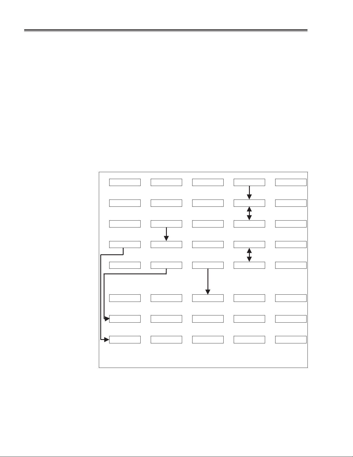
The Service Menus Service Menus are provided to facilitate functional verification. The Service
Menus (Figure 2-1) contain several functions for testing and verifying the
Cuff channel, display, invasive pressure channel (models 104 and 106 only),
and printer. During the functional verification procedure, the Service Menu
functions will be accessed to perform necessary tests.
SENSORS FREEZESYSTEMDISPLAYALARMS
PRINTER MAIN MENUMORENET OFFPROGRAM
INSERV MAIN MENUMORETIME/DAYSERVICE
CUFF TST MAIN MENUMORESPO2 TEST
LOOP TEST MAIN MENUOUT TEST
CYCLE MAIN MENUBORDERCOLUMN 2COLUMN 1
PUMP TST MAIN MENUCUFF CALAUTO PMP
a
IBP TEST applicable only for Propaq 104, 106.
b
SPO2 TEST intended for factory use with SpO2 option.
c
NET TEST applicable only for Network option.
IBP TEST
PIXL TST
a
Fig. 2-1. The Service Menus, Version 7
b
c
MAIN MENUMORENET TEST
VERSION 7.x
2-4 810-0334-01 Calibration/Maintenance Manual
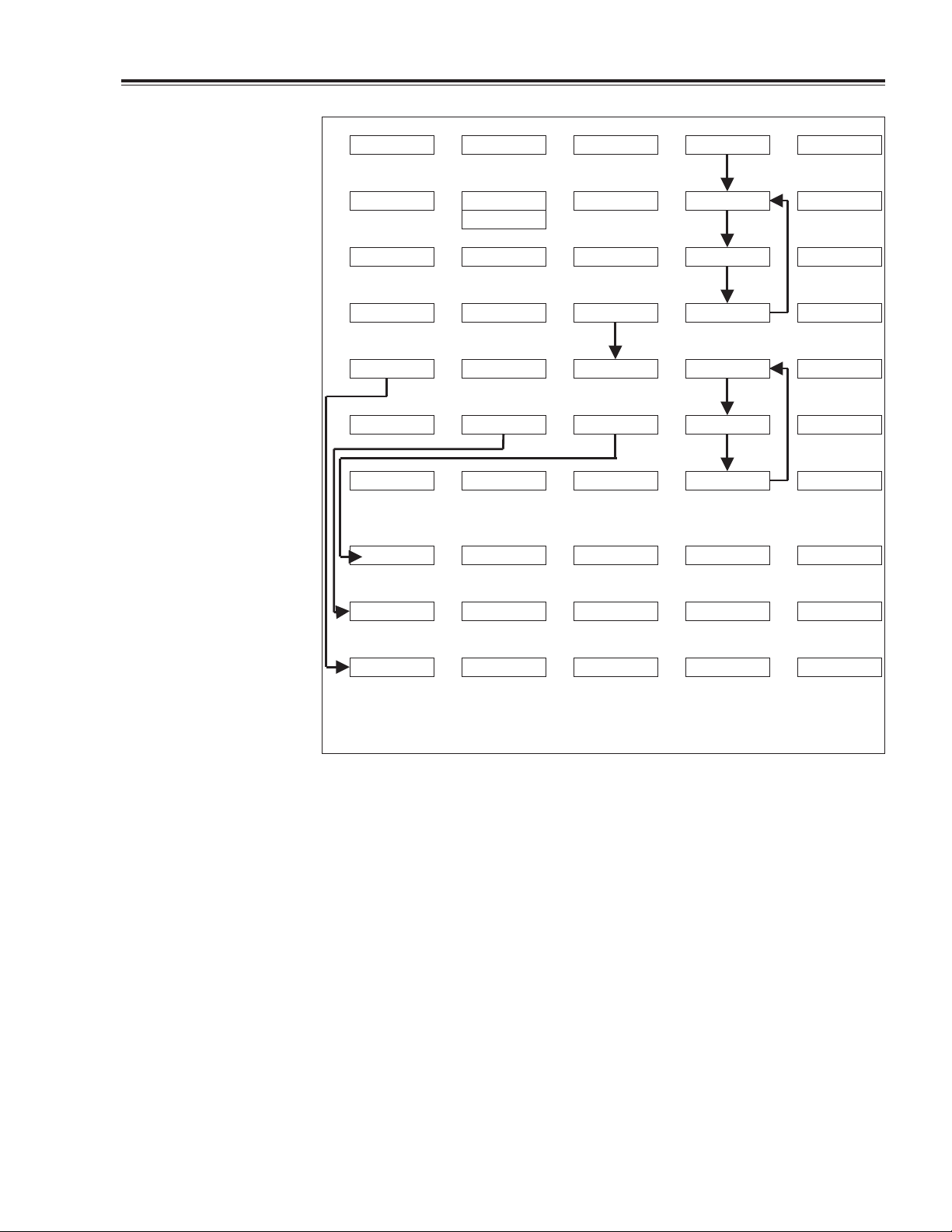
Page 28
Propaq 100-Series Monitors Section 2—Installation and Service
SENSORS FREEZESYSTEMDISPLAYALARMS
d
SNAPSHOT
INSERV MAIN MENUMORETIME/DAYPROGRAM
CHANGE MAIN MENUMORESERVICENEXT
CUFF TST MAIN MENUMORESPO2 TEST
TEMP TEST MAIN MENUMORENET TEST
CO2 TEST
LOOP TEST MAIN MENUOUT TEST
CYCLE MAIN MENUBORDERCOLUMN 2COLUMN 1
e
IBP TEST
PIXL TST
d
a
MAIN MENUMORENET OFFPRINTER
b
c
MAIN MENUMORE
PUMP TST MAIN MENUCUFF CALAUTO PMP
a
IBP TEST applicable only for Propaq 104, 106.
b
SPO2 TEST intended for factory use with SpO2 option.
c
NET TEST applicable only for Network option.
d
Depends on option installed.
e
Applicable only for CO2option.
Fig. 2-2. The Service Menus, Version 8
VERSION 8.x
Menu functions are accessed by pressing one or a series of buttons below
menu labels on the monitor display. Button presses to access any function in
the Propaq are shown in this manual with the > character separating the
names of the buttons to be pressed. For example, SENSORS > ECG >
LEAD means starting from the Main Menu, press the SENSORS button,
then the ECG button, and finally the LEAD button.
The Service Menu is activated by pressing from the Main Menu (Version
7.x software) SYSTEM > MORE > SERVICE, or (Version 8.x software)
SYSTEM > MORE > MORE > SERVICE.
NOTE
In the following procedures, where Version 8.x button presses differ
from Version 7.x button presses, both versions are given. Otherwise,
button presses are the same for both versions.
Calibration/Maintenance Manual 810-0334-01 2-5
Page 29

Section 2—Installation and Service Propaq 100-Series Monitors
Equipment Required Table 2-2 lists all the equipment needed to perform a functional verification.
Some equipment can be manufactured. See Appendix A for information on
manufacturable test equipment.
Table 2-2. Equipment Required for Functional Verification
Equipment Description
Mercury-column Manometer with Bulb (400 mmHg), Baumanometer 14-383 wall
mount Manometer or equivalent
50 MHz Triggered Sweep Oscilloscope, Tektronix 2225 or equivalent
Variable DC Power Supply, 0-36 V, 3A, VIZ WP-715A or equivalent
Patient Simulators, Dynatech/Nevada 213A, 215A, or 217A with Temperature and
EGG Cable/Leads
Electromedics 37° C Temperature Sensor Simulator (See Appendix A)
IBP Simulator, 5 µV/mmHg/volt, Fogg Systems BP48C, BP28, or MDE Datasim
6000 with IBP cables
Adult Cuff Kit, Protocol PN 008-0006-XX
Protocol Cuff Calibration Kit, Protocol PN 008-0012-XX
Power Supply Adapter Cables (See Appendix A)
Propaq AC Power Adapter
North American, 120 V, 60 Hz, Protocol PN 503-0002-00
International, 220-240 V, 50-60 Hz, Protocol PN 503-0002-20
Japanese, 100 V, 50-60 Hz, Protocol PN 503-0002-30
Safety Analyzer, Dynatech/Nevada (formerly Neurodyne-Dempsey), 431F-1D or
equivalent
Rod-L Model M100AVS5 High-Voltage Potential Tester, or equivalent
NELLCOR Pocket Tester, PT-2500
Test gas source: dry 4% to 10%* CO
Tw o rubber test tube stoppers, with 1/8" to 1/4" vent holes opened through (for
CO
tests)
2
*Gas may be between 4 and 10%, but exact CO2concentration must be certified within
±0.01%. See procedure later in this section for determining partial pressure.
, balance air (with flow meter)
2
Procedure NOTE
If the monitor has been stored for longer than one month
without the monitor connected to the ac adapter (for
recharging), the battery voltage should be checked. The battery
may need to be replaced if it cannot hold a charge.
The functional verification must be done only when the monitor is fully
assembled. Equipment required to perform this procedure is shown in Table
2-2. Most items not commercially available can be made according to the
information in Appendix A.
2-6 810-0334-01 Calibration/Maintenance Manual
Page 30

Propaq 100-Series Monitors Section 2—Installation and Service
NOTE
If you plan to use a Dynatech/Nevada model 213A, 215A, or 217A
Patient Simulator to simultaneously simulate ECG and invasive
blood pressure, see Appendix B for important information.
If the monitor did not pass the functional verification, or when it is time to
do a routine calibration, see the Calibration Procedure in Section 3.
Functional verification and safety checks must always be done after monitor
disassembly or calibration, or whenever there is a question about the safety
of the patient functions.
NOTE
Before starting the verification procedures, charge the battery
for at least 8 hours with the monitor turned off. (Charge for 12
hours if a Printer or SpO
module is attached.)
2
Power System The following steps check the integrity of the power system.
1. If the ac power adapter is not plugged in, plug it into an ac socket
with the correct voltage and connect it to the monitor’s right side panel
dc power connector.
2. Check that the green
BATTERY CHARGING indicator lights.
3. Disconnect the power adapter from the monitor. Check that the
BATTERY CHARGING indicator turns off.
CAUTION
In the next steps, carefully check for the proper polarity of the
connection between the power supply and the monitor. If voltage
is applied with the wrong polarity, it will blow an internal fuse
(F1 on the Recharger board). Refer to the diagram on the
monitor’s right side panel for proper polarity.
4. Turn on the dc power supply and set it for 15 V
5. Using the power supply adapter cable (constructed as shown in
Appendix A), connect the power supply to the monitor’s dc input
connector on the right side panel.
6. Check that the
BATTERY CHARGING LED indicator lights.
7. Check that the current draw from the supply is less than 650 mA.
NOTE
Initial charge current can be as high as 880 mA. However, as the
battery charges, the current will decrease. A fully charged battery
draws less than 100 mA. You should notice the current draw slowly
drop the longer the dc supply is connected to the monitor.
±0.5 V.
8. Turn off the power supply.
9. Disconnect the supply from the monitor.
Calibration/Maintenance Manual 810-0334-01 2-7
Page 31

Section 2—Installation and Service Propaq 100-Series Monitors
Button Tests The following steps check the operation of the buttons.
1. Turn on the monitor.
2. Make sure that no error messages appear and the monitor correctly
powers up.
3. With the Main Menu displayed
a. press one of the buttons
b. check that the menu changed
c. press the MAIN MENU button
d. repeat steps 3a through 3c until all buttons have been checked.
4. Make sure that the Main Menu is displayed when you are done.
Display The following steps check the display.
1. Press MAIN MENU.
2. For Version 8.x software, press SYSTEM > MORE > MORE >
SERVICE > MORE > PIXL TST > CYCLE to start the display tests
(usually starts at COLUMN1).
For Version 7.x software, press SYSTEM > MORE > SERVICE >
MORE > PIXL TST > CYCLE.
3. Check that all pixels in the activated columns are turned on.
4. Press the left button to advance to the next test, COLUMN2.
5. Check that all pixels in the activated columns are turned on.
6. Press the left button to advance to the next test, BORDER.
7. Check that all pixels around the perimeter of the display are turned off.
8. Press any but the left button to stop the tests.
9. Press MAIN MENU.
10 .Press SYSTEM > MORE > TIME/DAY and check that the displayed
time of day and date are correct. If they are not, correct them using the
NEXT and UP or DOWN buttons and set them with the ENTER
button.
The clock should be accurate to ±2 seconds per day or ±1 minute
per month. If the clock does not meet these specifications, complete
the calibration of the Clock/Calendar listed in Section 3.
2-8 810-0334-01 Calibration/Maintenance Manual
Page 32

Propaq 100-Series Monitors Section 2Installation and Service
ECG Channel &
Alarm Indicators
The following steps check the ECG channel and the alarm indicator drivers.
1. Connect the ECG channel to the patient simulator.
2. Set the simulator as follows:
normal sinus rhythm
80 beats per minute (bpm)
1 mV amplitude
3. Set the monitor as follows (from the Main Menu, press the keys
indicated in parentheses):
Lead II (SENSORS > ECG > LEAD)
1 mV ECG size (SENSORS > ECG > SIZE)
25 mm/Sec sweep speed (SENSORS > ECG > mm/SEC)
ALL ALARMS OFF (ALARMS > ALL ALRM)
Version 7.x- Tone to LOW (DISPLAY > MORE > TONE)
Version 8.x- Tone to LOW (SENSORS > ECG > MORE > TONE)
4. Check that a normal sinus rhythm ECG waveform is displayed with a
peak-to-peak height equal to that of the reference pulse at the left side
of the display (18
±2 pixels high, after subtracting 1 pixel from the
total for trace thickness). There should be a soft beep tone with each
QRS event.
NOTE
The patient simulator recommended in Table 2-2 provides a 1mV
output at Lead II. Other simulators may provide 1 mV at different
leads. If you use a simulator other than the one recommended,
check the simulator's specifications.
5. From the Main Menu, press (V7.x) DISPLAY > MORE > TONE, or
(V8.x) SENSORS > ECG > MORE > TONE.
6. Check that the tone turned off.
7. Press TONE twice more and check for high and medium tones.
This affects only the heart beat tone. Alarm tones are not affected.
Turn the tone off for the remainder of the functional verification.
8. Press MAIN MENU.
9. Check that the monitor's heart rate display is 80 ±4 bpm.
10. Remove one ECG lead wire.
Calibration/Maintenance Manual 810-0334-01 2-9
Page 33

Section 2—Installation and Service Propaq 100-Series Monitors
11. Check that an equipment alarm occurs. The LEAD FAIL message
should accurately indicate the removed lead.
12. Disconnect one of the two remaining leads.
13. Check that an equipment alarm occurs with a
LEAD FAIL MULTIPLE
message.
14. Reconnect all leads.
15. Press MAIN MENU.
16. Check that the
ALARM(S) OFF light is on.
17. Press ALARMS > STAT SET to automatically set heart rate alarm
limits.
18. Set the simulator heart rate outside a heart rate alarm limit.
19. Check that an alarm violation occurs with the tone and
ALARM light
on.
NOTE
The alarm tone may be set to high, med or low through DISPLAY
> MORE > MORE > NEXT (press until “alarm tone volume”
function appears) > CHANGE.
20. Press ALL ALRM to turn off alarms.
21. Check that the tone turns off.
22. Press MAIN MENU.
23. Adjust the simulator heart rate to 80 bpm.
24. Set the simulator for PACED RHYTHMS, NON-FUNCTION.
25. If pacer indicator is not on, press SENSORS > ECG > MORE >
PACER to turn on the pacer indicator.
A dashed line between the heart rate numeric and waveform
windows indicates the pacer indicator is on.
26. Check that a dashed vertical line is displayed on the ECG waveform
each time a pacer pulse occurs.
27. Check that the heart rate numeric is displayed as three horizontal
dashed lines.
28. Press MAIN MENU.
2-10 810-0334-01 Calibration/Maintenance Manual
Page 34

Propaq 100-Series Monitors Section 2—Installation and Service
P1, P2 The following steps verify the operation of one invasive pressure channel
(P1). Repeat the steps for checking P2 of a Propaq 106. If you are verifying
a Propaq 102, skip this part of the procedure.
NOTE
Check that the P1 and P2 waveforms are turned on in the wave
select window.
CAUTION
Many blood pressure simulators are not intended to be used as
a calibration standard. The simulator you use should have an
accuracy of at least 1%. Check your simulator’s specifications.
NOTE
If you are using the D ynatech/Nevada model 213A, 215A, or 217A
patient simulator, do not simultaneously monitor ECG and invasive
blood pressure (IBP) unless the modification to the simulator is
performed as described in Appendix B. If you do not wish to modify
your sim ulator, use ECG and IBP independently.
1. Disconnect the ECG cable from the monitor.
(Disconnecting an active channel initiates an equipment alarm.)
2. Press the DISABLE button to remove the alarm screen.
3 .Plug the pressure simulator into the monitor’s P1 connector (use the
P2 connector if verifying P2).
4. Set the simulator to 0 mmHg.
5. Check that P1 NOT ZEROED (or P2 NOT ZEROED) is displayed in
the blood pressure numerics window.
(The pressure scale does not appear until the pressure channel has
been zeroed.)
6. Zero the pressure channel by pressing SENSORS > INV PRS >
MORE > ZERO P1 (Press MORE twice to access ZERO P2).
7. Check that P1 ZEROED (or P2 ZEROED) is displayed.
8. Check that the mean pressure numeric is 0 mmHg ±2 mmHg.
9. Set the pressure simulator to 200 mmHg.
10. Check that the mean pressure numeric is 200 mmHg ±2 mmHg.
11. Set the pressure simulator to 0 mmHg.
12 .Press MORE > RESCALE.
13. Check that the displayed pressure waveform noise is no larger than 6
pixels p-p, after subtracting 1 pixel from the total for trace thickness.
14. Press MAIN MENU.
Calibration/Maintenance Manual 810-0334-01 2-11
Page 35

Section 2—Installation and Service Propaq 100-Series Monitors
CUFF Channel NOTE
In the following steps, the monitor’s displayed pressure must be
checked against a calibrated mercury-column manometer.
1. Connect the cuff, manometer with bulb, and the monitor together with
the Cuff Calibration Kit. See Figure 2-3.
2. Wrap the adult cuff around a cylindrical object about the size of an
adult’s arm.
3. Press SYSTEM > MORE > (V8.x press MORE again) SERVICE >
CUFF TST > CUFF CAL.
The Propaq pneumatic components now prevent cuff air from
flowing through the vent port to the atmosphere for a ten-minute
period. If steps 4 through 9 take longer than ten minutes, simply
press CUFF CAL again.
4. Close the valve on the bulb and squeeze the bulb to inflate the cuff to
250 mmHg as shown on the mercury-column manometer.
5. Check that the reading on the monitor’s display is 250±4 mmHg.
6. Reduce the pressure to 100 mmHg and check that the displayed
pressure is 100±2mmHg.
Fig. 2-3. Cuff Calibration Kit Attachments
2-12 810-0334-01 Calibration/Maintenance Manual
Page 36

Propaq 100-Series Monitors Section 2—Installation and Service
7. Reduce the pressure to 0 mmHg and check that the displayed pressure
is 0±2 mmHg. Close the bulb valve.
8. Press PUMP TST.
9. Check that the pump inflates the cuff to approximately 229 mmHg
within 10 seconds.
10. Observe the leak rate display on the monitor screen. Check that the
leak rate is less than 10 mmHg/min after one minute.
11. With the bulb valve closed, while observing the manometer, inflate the
cuff until the monitor automatically vents the pressure.
12. Check that the manometer reading is approximately 260 mmHg when
the pressure is vented.
13. Press MAIN MENU.
14. Disconnect the cuff and Cuff Calibration Kit.
15. Disable the equipment alarm by pressing DISABLE.
Temperature NOTE
The Propaq 106 does not support Electromedics tem perature
probes. Steps 5 and 6 below do not apply to the Propaq 106.
1. Insert a YSI 400 Series calibrated temperature probe simulator into the
T1 jack.
2. Check that T1 temperature is ±0.2°F (±0.1°C) of the calibration
temperature.
3. Replace the YSI 400 simulator with a YSI 700 Series probe simulator.
4. Check that T1 temperature is ±0.2°F (±0.1°C) of the calibration
temperature.
5. Insert an Electromedics 2100 Series calibrated temperature probe
simulator into the T2 jack. (See Appendix A).
6. Check that the displayed temperature (T2) is ±0.2°F (±0.1°C) of the
calibration temperature.
Calibration/Maintenance Manual 810-0334-01 2-13
Page 37

Section 2—Installation and Service Propaq 100-Series Monitors
Battery Capacity
Test
This procedure checks the capacity of the battery to ensure that it is capable
of holding a charge.
NOTE
A new battery should pass the following test. The run time of older
batteries will decrease proportionally with age. Replacement is
recommended when the run time becomes insufficient for the
monitor’s application.
1. Use the ac power adapter and charge the monitor for at least 8 hours
with the monitor turned off (12 hours if a printer or pulse oximeter is
attached).
2. Disconnect the power adapter.
3. Set the monitor as follows: CUFF in manual mode.
4. Run the monitor for 8 hours.
5. Check that the monitor did not automatically turn off. (See Propaq
Users Guide for a description of how the Propaq responds to falling
battery voltage).
6. Use the ac power adapter and charge the monitor for at least 8 hours
with the monitor turned off. (Charge at least 12 hours if an EMP or
pulse oximeter is attached.)
SpO2Checks The following steps check the operation of the pulse oximetry option (SpO
1. Disconnect all test cables from the monitor’s patient channel
connectors. (It is not necessary to disconnect the cuff hose.)
2. Connect the NELLCOR SpO
test fixture to the Propaq’s D-type
2
connector.
The test fixture has no on/off switch. It automatically turns on with
the monitor power.
3. Turn off all alarms by pressing ALARMS > ALL ALRM from the
Main Menu.
4. Press MAIN MENU.
5. Turn on the SpO
waveform in the wave select window (DISPLAY >
2
MORE > WAVE SEL).
).
2
2-14 810-0334-01 Calibration/Maintenance Manual
Page 38

Propaq 100-Series Monitors Section 2Installation and Service
6. Check that the SpO2numeric is 81 ±2.
7. Check that the pulse rate is 40
±3.
8. Check that the waveform shape is similar to Figure 2-4.
9. Check that the speaker is sounding with every pulse indicated on the
display.
10. Check that the speaker volume changes according to the TONE
setting (V7.x-DISPLAY > MORE > TONE;
V8.x-SENSORS > ECG > MORE > TONE).
11. Disconnect the SpO
test fixture from the Propaq.
2
12. Check that an equipment alarm occurs.
13. Press SUSPEND.
NOTE
The following steps require a suitable ECG/SpO
provide a synchronized ECG and SpO
signal. Instead of a
2
simulator to
2
simulator, you can connect ECG electrodes to yourself and use a
NELLCOR sensor on your finger.
14. Provide synchronized ECG and SpO
15. Press SENSORS > MORE (if necessary) > SpO
signals to the Propaq.
2
> MORE > C-LOCK
2
until C-LOCK is turned ON.
16. Check that the SpO
signal and ECG signals appear normal and
2
"normal" readings appear on the monitor.
17. Unplug the ECG connector from the Propaq.
18. Check that the NO C-LOCK message alternates with the time of day.
19. Disconnect all cables from the Propaq.
Fig. 2-4. SpO2 Waveform Shape
Calibration/Maintenance Manual 810-0334-01 2-15
Page 39

Section 2—Installation and Service Propaq 100-Series Monitors
Printer Tests The following steps check the functionality of the printer.
NOTE
Functional verification should be performed on the monitor before
beginning the printer tests. The monitor must be functioning
properly in order to perform printer tests.
1. Turn on the monitor and check that the green LED on the printer’s
front panel lights after 2 to 3 seconds.
2. Connect the patient simulator to the monitor.
3. Set the patient simulator for ECG, normal sinus rhythm.
4. Check that the monitor displays a normal ECG signal.
5. Press and hold in the printer’s PAPER FEED button.
Paper should feed out the side of the printer as long as the button is
held in.
6. Release the PAPER FEED button.
7. Press the printer’s SNAPSHOT button.
The printer should print an eight-inch strip of a normal ECG wave
form. The paper should stop only after the entire waveform has been
fed out of the printer.
8. Press the printer’s START/STOP button.
The printer should begin printing a normal ECG waveform without
stopping.
9. Press the START/STOP button to stop printing.
10. Press the START/STOP button to start printing.
2-16 810-0334-01 Calibration/Maintenance Manual
Page 40

Propaq 100-Series Monitors Section 2—Installation and Service
11. Lay the Propaq on its back while the printer is printing.
12. Completely open the paper door on the bottom of the Expansion
Module.
13. Check that the printer stops printing, that the green LED is not lit, and
that an equipment alarm and CHECK DOOR message appear on the
monitor screen.
14. Cut the printer paper from the roll, leaving a strip of paper in the
printer mechanism.
15. Close the paper door and set the monitor upright.
16. Press the START/STOP button.
17. After the printer runs out of paper, check that the green LED is not lit
and that an equipment alarm and PAPER OUT message appear on the
monitor screen.
18. Open the printer door and replace the end of the paper roll in the
printer.
19. Close the paper door and set the monitor upright.
20. Check that the green LED lights.
21. Press and hold in the printer’s PAPER FEED button and then press the
START/STOP button.
22. Check that a test printout similar to Figure 2-5 is printed.
23. Turn off the monitor and simulator, and disconnect the simulator from
the monitor.
Fig. 2-5. Printer Test Printout.
Calibration/Maintenance Manual 810-0334-01 2-17
Page 41

Section 2—Installation and Service Propaq 100-Series Monitors
CO2Functional
Verification
This procedure verifies CO2accuracy. If the verification test results are
within specifications, board calibration is not required.
Functional verification and calibration procedures require calculations of
local barometric pressure and partial pressure of the test gas source (in
mmHg) to compare to Propaq displayed values.
Determine Local Barometric Pressure
1. Determine local altitude above sea level. For worldwide locations, obtain
altitude from local geological maps (U.S.G.S. maps in the United States)
or other local references. Refer to Table 2-3 to determine local
uncorrected pressure (LUP) for established altitude.
2. Determine ATIS reported pressure (inches or millimeters of Hg).
For U.S. locations, consult local telephone directories to obtain the
Automated Terminal Information Service (ATIS) number, which is
typically listed under United States Government Offices, Department
of Transportation, Federal Aviation Administration, Air Traffic
Control Towers. Among various statistics reported is the “altimeter”,
which is given in four integers. The four digits represent the
barometric pressure as referred to sea level, in units of inches of
mercury, with an assumed decimal point occurring between the
second and third numbers.
For worldwide locations, equivalent altimeter statistics, in millimeters
of mercury, may be obtained from local agencies.
NOTE
The difference in altitude between the calibration site and the ATIS
site should not be greater than 30 m or 100 ft.
3. Determine local barometric pressure using LUP and ATIS. Apply the
ATIS and LUP values to the following formula to calculate the local
barometric pressure (mmHg):
Local Barometric Pressure =
•
0.033421
0.00131579
LUP•ATIS (ATIS in inches of mercury)
•
LUP•ATIS(ATIS in millimeters of mercury)
EXAMPLE 1:
Step 1: The user’s altitude is 5000 feet. The LUP from Table 2-3 is 632.35.
Step 2: The reported ATIS is 30.09 (“Altimeter: three zero zero niner.”)
Step 3: Multiply 632.35 (LUP) times 30.09 (ATIS) times 0.033421
Local Barometric pressure = 635.92 mmHg
EXAMPLE 2:
Step 1: The user’s altitude is 1000 meters. The LUP from Table 2-3 is
674.11
Step 2: The reported ATIS is 764.29 mmHg.
Step 3: Multiply 674.11 (LUP) times 764.29 (ATIS) times 0.00131579
Local Barometric pressure = 677.92 mmHg
2-18 810-0334-01 Calibration/Maintenance Manual
Page 42

Propaq 100-Series Monitors Section 2—Installation and Service
Determine Partial Pressure of Test Gas Source
Determine the partial pressure of test gas source. Multiply the local
barometric pressure as determined in step 3 times the certified percentage
+.01% accuracy) of the test gas.
(
EXAMPLE:
Step 1: The local barometric pressure as calculated in step 3, Example 1 is
635.92
Step 2: The certified CO
Step 3: Determine CO
CO
2
Table 2-3. Local Uncorrected Barometric Pressure
gas percentage is 5.00%.
2
partial pressure. Multiply 635.92 times 0.0500
2
partial pressure = 31.8 mmHg
as a Function of Altitude
Altitude
(Feet)
-2000 816.56 1000 732.93 4000 656.38 10000 522.65
-1900 813.66 1100 730.27 4200 651.52 10333 515.93
-1800 810.76 1200 727.62 4400 646.68 10667 509.26
-1700 807.87 1300 724.97 4600 641.88 11000 502.69
-1600 804.99 1400 722.33 4800 637.10 11333 496.18
-1500 802.11 1500 719.70 5000 632.35 11667 489.72
-1400 799.25 1600 717.07 5200 627.64 12000 483.34
-1300 796.39 1700 714.46 5400 622.95 12333 477.04
-1200 793.54 1800 711.85 5600 618.28 12667 470.78
-1100 790.70 1900 709.25 5800 613.65 13000 464.60
-1000 787.87 2000 706.65 6000 609.04 13333 458.50
-900 785.05 2100 704.07 6200 604.47 13667 452.44
-800 782.23 2200 701.49 6400 599.92 14000 446.46
-700 779.42 2300 698.92 6600 595.40 14333 440.55
-600 776.62 2400 696.36 6800 590.90 14667 434.68
-500 773.83 2500 693.80 7000 586.44 15000 428.89
-400 771.05 2600 691.26 7200 582.00 15333 423.17
-300 768.28 2700 688.72 7400 577.58 15667 417.49
-200 765.51 2800 686.18 7600 573.20 16000 411.89
-100 762.75 2900 683.66 7800 568.84 16333 406.35
0 760.00 3000 681.14 8000 564.51 16667 400.86
100 757.26 3100 678.63 8200 560.21 17000 395.44
200 754.52 3200 676.13 8400 555.93 17333 390.08
300 751.80 3300 673.64 8600 551.68 17667 384.76
400 749.08 3400 671.15 8800 547.45 18000 379.52
500 746.37 3500 668.67 9000 543.26 18333 374.34
600 743.67 3600 666.20 9200 539.08 18667 369.20
700 740.97 3700 663.73 9400 534.94 19000 364.13
800 738.28 3800 661.27 9600 530.82 19333 359.12
Pressure
(mmHg)
Altitude
(Feet)
Pressure
(mmHg)
Altitude
(Feet)
Pressure
(mmHg)
Altitude
(Feet)
Pressure
(mmHg)
Calibration/Maintenance Manual 810-0334-01 2-19
Page 43

Section 2—Installation and Service Propaq 100-Series Monitors
Table 2-3. (Cont) Local Uncorrected Barometric Pressure
as a Function of Altitude
Altitude
(Feet)
900 735.61 3900 658.82 9800 526.72 19667 354.15
1000 732.93 4000 656.38 10000 522.65 20000 349.24
Altitude
(Meters)
-700 825.23 1000 674.11 2700 546.23 4400 438.74
-650 820.43 1050 670.03 2750 542.79 4450 435.86
-600 815.65 1100 665.98 2800 539.37 4500 432.99
-550 810.89 1150 661.94 2850 535.96 4550 430.14
-500 806.15 1200 657.92 2900 532.58 4600 427.31
-450 801.43 1250 653.92 2950 529.21 4650 424.49
-400 796.74 1300 649.94 3000 525.85 4700 421.69
-350 792.07 1350 645.98 3050 522.52 4750 418.90
-300 787.43 1400 642.04 3100 519.20 4800 416.12
-250 782.80 1450 638.12 3150 515.90 4850 413.36
-200 778.20 1500 634.22 3200 512.62 4900 410.62
-150 773.61 1550 630.34 3250 509.35 4950 407.89
-100 769.05 1600 626.48 3300 506.10 5000 405.18
-50 764.52 1650 622.63 3350 502.87 5050 402.48
0 760.00 1700 618.81 3400 499.65 5100 399.79
50 755.51 1750 615.00 3450 496.45 5150 397.12
100 751.03 1800 611.22 3500 493.27 5200 394.46
150 746.58 1850 607.45 3550 490.10 5250 391.82
200 742.15 1900 603.70 3600 486.95 5300 389.19
250 737.74 1950 599.97 3650 483.82 5350 386.58
300 733.35 2000 596.26 3700 480.70 5400 383.98
350 728.99 2050 592.57 3750 477.60 5450 381.39
400 724.64 2100 588.89 3800 474.51 5500 378.82
450 720.32 2150 585.24 3850 471.44 5550 376.27
500 716.01 2200 581.60 3900 468.39 5600 373.72
550 711.73 2250 577.98 3950 465.36 5650 371.20
600 707.47 2300 574.38 4000 462.33 5700 368.68
650 703.23 2350 570.80 4050 459.33 5750 366.18
700 699.01 2400 567.24 4100 456.34 5800 363.69
750 694.81 2450 563.69 4150 453.37 5850 361.22
800 690.63 2500 560.16 4200 450.41 5900 358.76
850 686.47 2550 556.65 4250 447.47 5950 356.31
900 682.33 2600 553.16 4300 444.54 6000 353.88
950 678.21 2650 549.68 4350 441.63 6050 351.46
1000 674.11 2700 546.23 4400 438.74 6100 349.05
Pressure
(mmHg)
Pressure
(mmHg)
Altitude
(Feet)
Altitude
(Meters)
Pressure
(mmHg)
Pressure
(mmHg)
Altitude
(Feet)
Altitude
(Meters)
Pressure
(mmHg)
Pressure
(mmHg)
Altitude
(Feet)
Altitude
(Meters)
Pressure
(mmHg)
Pressure
(mmHg)
2-20 810-0334-01 Calibration/Maintenance Manual
Page 44

Propaq 100-Series Monitors Section 2—Installation and Service
Functional Verification Procedure
This procedure verifies CO
accuracy. If the verification test results are
2
within specifications, board calibration is not required. If verification test
results exceed specification limits, calibration as instructed in Section 3
MAY or MAY NOT be required-see Table 2-4 for possible sources of errors
in testing. Before proceeding to calibration, check test parameters as
indicated in Table 2-4 to minimize errors.
1. Connect a CO
sensor with airway adapter to the Propaq CO2input
2
connector.
2 .Power the Propaq on and use the menu keys to disable the patient
alarms. Set the CO
measurement UNITS to millimeters of mercury
2
(mmHg).
3. Allow the monitor and sensor to warm up for a minimum of 15 minutes.
NOTE
Possible errors may be caused if the area has high background CO
2
levels or if CO2has been forced outside of the airway adapter and
into the sensor itself. To reduce background CO
level, the area
2
should be well ventilated and, preferably, the technician should be
the only person present. If CO
allow 24 to 48 hours for the CO
4. After 15 minutes, check the CO
has been forced into the sensor,
2
to dissipate.
2
reading (of ambient room air) on the
2
Propaq display to be 1 mmHg, ±1 mmHg.
5. Procure two standard rubber test-tube stoppers and open a 1/8" to 1/4"
hole through each. Install the stoppers into each end of the sensor airway
adapter. Via the tubing/fitting combination, connect the CO
gas source
2
through the hole in the stopper on one end of the airway adapter. Leave
the hole in the stopper on the other end of the airway adapter open.
NOTE
Before performing steps 6 and 7, convert the percentage of the gas
source to partial pressure (mmHg) as instructed earlier in this
section.
6. Introduce a flow of test CO
at a rate of 60 to 200 ml/min into the
2
sensor airway adapter.
7. For test gas calculated partial pressure values of 30 mmHg or less, check
the CO
reading on the Propaq display to be within 3 mmHg. For test
2
gas calculated partial pressure values greater than 30 mmHg, check the
reading on the Propaq display to be within ±10% of the partial
CO
2
pressure value.
NOTE
If CO
test results are out of specification limits, refer to Table 2-4
2
for possible error sources. Verify test setup to minimize errors.
Calibration/Maintenance Manual 810-0334-01 2-21
Page 45

Section 2—Installation and Service Propaq 100-Series Monitors
Table 2-4. Possible Sources of CO2Verification Test Errors
Specification or Possible
Error
Incorrect/unknown
calibration gas
concentration
Cause of Error Correction
4 to 10%, certified to
within ±0.01%
Verify gas supply. Gas
may be between 4 and
10%. Once known,
convert percentage to
partial pressure (mmHg)
as instructed earlier in
this section
Barometer calibration
error
Known to within 3
mmHg
Determine ATIS, LUP,
local altitude values and
calculate local barometric
pressure. Calibrate Propaq
MSP board (see Section 3)
Insufficient/excessive
gas flow rate
Excessive back pressure
in cuvette
Between 60 and 200
ml/min
Back pressure should
not exceed 1 mmHg
Verify with flow meter
Connect gases as
instructed in verification
test
Air mixed with standard
gas
Gas temperature Gas temperature
entering airway adapter
Check integrity of test
setup
Store gas at room
temperature
should be at room
temperature
Cuvette error Results should not vary
more than 0.5 mmHg
Use other cuvette (airway
adapter)
due to cuvette tolerances
Thermal equilibrium
error
Sensor not warmed up Allow sensor/system to
operate in a 15 minute
warm-up period
High CO
reading with
2
sensor subject to room
air only
CO
forced outside of
2
airway adapter into
sensor. This is possible
during demonstration if
exhaled gases are blown
through hands cupped
around cuvette and
exhaled gases are forced
into sensor
Contain exhaled breath
through the inside of
cuvette only. Do not allow
gases to be forced outside
of cuvette and into sensor
housing. If CO
has been
2
forced into sensor, allow
24 to 48 hours for the
CO
to dissipate
2
2-22 810-0334-01 Calibration/Maintenance Manual
Page 46

Propaq 100-Series Monitors Section 2—Installation and Service
The following safety tests should be performed after any servicing which
requires opening the monitor.
Patient Isolation
Safety Checks
Patient Leakage (Risk) Current Test
Check leakage currents using a Dynatech/Nevada (formerly NeurodyneDempsey) 431F-1D Safety Analyzer or its equivalent. The source current
should not exceed 10 µA rms. The sink current, measured between the
isolated patient connections (ECG) and the dc power input connector of the
monitor, should not exceed 20 µA rms. See the analyzer’s operator’s manual
for the proper safety check procedure. Table 2-5 lists the proper connections
between the monitor, power adapter, and the safety analyzer for each test.
Note: because of the all-insulated construction of the monitor, the Enclosure
Leakage Current Test to ground is not performed.
Table 2-5. Electrical Connections for
Patient Leakage (Risk) Current Safety Tests
Monitor
Safety Test Power Adapter
Source
Current
Sink Current Not Used Connected to Ground
Plugged into
Analyzer Outlet
Connected to Power
Adapter
Connector on Analyzer
Dc Input
Monitor
Cable
RA
LA
LL
RA
LA
LL
Safety
Analyzer
RA
LA
LL
RA
LA
LL
Dielectric Strength (Hi-Pot) Test
Because of the close spacings of the monitor’s internal components and the
critical positioning of sheet insulation within the monitor, Protocol Systems
recommends that a dielectric strength test be performed following any
procedure in which the monitor is opened.
This test requires specialized equipment which may not be available at
hospital repair facilities. If that is the case, Protocol Systems, Inc., will
perform the safety test for a nominal charge with one-day turnaround. See
Repair and Upgrade Support at the beginning of this Section.
WARNING
The Hi-Pot test is extremely hazardous. Only qualified service
personnel should perform this test. Conduct the test only on an
insulated table top, away from other persons and equipment.
Calibration/Maintenance Manual 810-0334-01 2-23
Page 47

Section 2—Installation and Service Propaq 100-Series Monitors
Use a Rod-L Model M100AVS5 High-Voltage Potential Tester, or
equivalent. See the Model M100AVS5 manual for operating information and
safety recommendations.
1. Set the high voltage potential of the tester to one of the values specified
in Table 2-6.
2. Connect the high-voltage output lead of the tester to the ECG leads,
using a dedicated patient cable reserved for use only in such tests.
3. Connect the tester’s chassis-connected return lead to the monitor’s dc
input connector, using a suitable plug.
4. Apply the test voltage for one second. The tester must not indicate
dielectric breakdown.
WARNING
If any dielectric breakdown occurs, do not use the monitor.
All internal sheet insulation barriers must be properly installed.
Check the monitor to determine the cause of dielectric breakdown; then repair the monitor or return the monitor to Protocol
Systems for repair.
Table 2-6. Summary of Connection Points and
Tester’s High-Voltage
Terminal Connection
All ECG Leads on
Patient Cable,
Connected Together
High-Voltage Test Potentials
Tester’s Grounded
Return Connection
Shell of Monitor’s
Dc Power Input
Connector
High-Voltage
Test Potential
4,000 V ac rms 1 Second
Time Duration
of Test
2-24 810-0334-01 Calibration/Maintenance Manual
Page 48

Section 3
Calibration
Introduction This section provides a calibration procedure that allows you to calibrate the
Propaq 100-series monitor to factory specifications. Calibration procedures
should be performed only by qualified service personnel.
These procedures should be performed whenever necessary as indicated in
Table 3-1. See Section 2 for the functional verification procedure.
Table 3-1. Recommended Calibration Intervals
Interval/Condition Perform
Semi-annually Complete Functional Verification and
Monitor is dropped, in an accident, or
suspected rough handling.
Suspected malfunction with all or part
of functions.
Monitor fails Functional Verification. Repair followed by Functional
Module has been replaced and monitor
fails Functional Verification.
Every three months Check the calibration of the CO
Safety Check
Complete Functional Verification and
Safety Check.
Functional Verification for suspected
function(s).
Verification and Calibration as required.
Repair followed by Functional
Verification and Calibration as required.
sensor.
2
NOTE
Protocol Systems recommends that both a patient leakage (risk)
current test and a dielectric strength test be performed following
any procedure which requires opening the monitor. These two tests
are described at the end of Section 2.
Equipment Required Table 3-2 lists all the equipment needed to perform a complete calibration
including the functional verification procedure in Section 2, Installation and
Service. Some equipment can be manufactured. See Appendix A for
information on manufacturable test equipment.
Calibration/Maintenance Manual 810-0334-01 3-1
Page 49

Section 3—Calibration Propaq 100-Series Monitors
Table 3-2. Equipment Required—Calibration and Functional Verification
Functional
Description
Verification Calibration
DMM, 4 1/2 Digit, Fluke 8050A or equivalent X
Mercury-column Manometer with Bulb (400 mmHg),
XX
Baumanometer 14-383 wall-mount Manometer or
equivalent
50 MHz Triggered Sweep Oscilloscope, Tektronix 2225
XX
or equivalent
Frequency Counter, Beckman UC-10 or equivalent X
Variable DC Power Supply, 0-36 V, 3A, VIZ WP-715A
XX
or equivalent
Patient Simulators
a
, Dynatech/Nevada 213A, 215A, or
XX
217A with Temperature and ECG Cable/Leads
Electromedics 37° C Temperature Sensor Simulator
XX
(See Appendix A)
IBP Simulator, 5 µV/mmHg/volt, Fogg Systems BP48C,
XX
BP28, or MDE Datasim 6000 with IBP cables
Battery Substitution Plugs (See Appendix A) X
Battery Temperature Sensor S ubstitution Plug
X
(See Appendix A)
Adult Cuff Kit, Protocol PN 008-0006-00 X X
Protocol Cuff Calibration Kit, Protocol PN 008-0012-00 X X
Protocol Analog Output Cable, Protocol PN 008-0017-00 X
Defib Sync Mating Connector, Miniature Circular DIN,
X
6-pin Male, Amphenol 750206-3, or equivalent
Defib Sync Marker In Pulse Source (See appendix A) X
Power Supply Adapter Cables (See Appendix A) X X
Propaq AC Power Adapter (Protocol Part Numbers)
X
North American, 120 V, 60 Hz, 503-0002-00
International, 220-240 V, 50-60 Hz, 503-0002-20
Japanese, 100 V, 50-60 Hz, 503-0002-30
Safety Analyzer, Dynatech/Nevada (Neurodyne-
X
Dempsey), 431F-1D or equivalent
Rod-L Model M100AVS5 High-Voltage Potential Tester,
X
or equivalent
Non-Conductive Screwdriver X
NELLCOR Pocket Tester, PT-2500 X
RS-423 Loopback Test Fixture (See Appendix A) X
Test gas source: dry 4 to 10% C O
CO
concentration must be certified to ±.01%. Convert
2
, balance air. Exact
2
X
percentage to partial pressure (mmHg); see Section 2
Tw o rubber test tube stoppers, with 1/8" to 1/4" vent
holes opened through (for CO
a
Do not simultaneously monitor ECG and IBP. See Appendix B.
2
tests)
X
3-2 810-0334-01 Calibration/Maintenance Manual
Page 50

Propaq 100-Series Monitors Section 3—Calibration
The Service
Menus
Accessing
Functions
For added convenience while performing functional verification and
adjustment procedures, Propaq monitors provide easy-to-use Service Menus
(Figure 3-1). Service Menu selections activate software-controlled tests and
functions. Using these functions and the instructions in this manual, a
complete calibration of the monitor can be accomplished in little time. The
Service Menu is accessed through the Propaq menu system.
The Service Menus (Figures 3-1 and 3-2) contain several functions for
testing and verifying the Cuff channel, display, invasive pressure channel
(models 104 and 106 only), and printer. During the procedures in this
manual, the Service Menu functions will be accessed to perform necessary
tests.
Menu functions are accessed by pressing one or a series of buttons below
menu labels on the Propaq display. Button presses to access any function in
the Propaq are shown in this manual with the > character separating the
names of the buttons to be pressed. For example, SENSORS > ECG >
LEAD means starting from the Main Menu, press the SENSORS button,
then the ECG button, and finally the LEAD button.
The Service Menu is activated by pressing from the Main Menu
(Version 7 software, Fig. 3-1) SYSTEM > MORE > SERVICE, or (for
Version 8 software, Fig. 3-2) SYSTEM > MORE > MORE > SERVICE.
SENSORS FREEZESYSTEMDISPLAYALARMS
PRINTER MAIN MENUMORENET OFFPROGRAM
INSERV MAIN MENUMORETIME/DAYSERVICE
CUFF TST MAIN MENUMORESPO2 TEST
LOOP TEST MAIN MENUOUT TEST
CYCLE MAIN MENUBORDERCOLUMN 2COLUMN 1
PUMP TST MAIN MENUCUFF CALAUTO PMP
IBP TEST
PIXL TST
a
b
c
MAIN MENUMORENET TEST
a
IBP TEST applicable only for Propaq 104, 106.
b
SPO2 TEST intended for factory use with SpO2 option.
c
NET TEST applicable only for Network option.
Fig. 3-1. The Service Menus, Version 7
Calibration/Maintenance Manual 810-0334-01 3-3
VERSION 7.x
Page 51

Section 3—Calibration Propaq 100-Series Monitors
SENSORS FREEZESYSTEMDISPLAYALARMS
d
SNAPSHOT
INSERV MAIN MENUMORETIME/DAYPROGRAM
CHANGE MAIN MENUMORESERVICENEXT
CUFF TST MAIN MENUMORESPO2 TEST
TEMP TEST MAIN MENUMORENET TEST
CO2 TEST
LOOP TEST MAIN MENUOUT TEST
CYCLE MAIN MENUBORDERCOLUMN 2COLUMN 1
e
IBP TEST
PIXL TST
d
a
MAIN MENUMORENET OFFPRINTER
b
c
MAIN MENUMORE
Calibration
Procedure
PUMP TST MAIN MENUCUFF CALAUTO PMP
a
IBP TEST applicable only for Propaq 104, 106.
b
SPO2 TEST intended for factory use with SpO2 option.
c
NET TEST applicable only for Network option.
d
Depends on option installed.
e
Applicable only for CO2option.
Fig. 3-2. The Service Menus, Version 8
VERSION 8.x
The following calibration procedure is provided to ensure that the monitor
performs according to Protocol’s specifications. After you complete this
calibration procedure, you must also perform the functional verification
procedure in Section 2.
The following calibration procedure includes checks and adjustments of the
recharger and power supply, invasive pressure channel, non-invasive blood
pressure channel (cuff), and the time of day clock. Verification of proper
circuit and channel operation of other channels is performed according to the
Functional Verification procedures in Section 2.
See Table 3-1 for information on service intervals.
See Table 3-2 for a list of the required test equipment for calibration. Some
of the test fixtures listed can be manufactured. See Appendix A.
Instructions for opening and closing the monitor’s case are provided in
Section 5.
3-4 810-0334-01 Calibration/Maintenance Manual
Page 52

Propaq 100-Series Monitors Section 3—Calibration
NOTE
Before performing this calibration procedure, charge the monitor
for at least 8 hours with the monitor turned off.
CAUTION
Make sure calibration is performed at a static-protected work
station. Static discharge can damage components in the Propaq
monitor.
Setup 1. Make sure the battery pack is fully charged.
2. If an EMP or pulse oximetry option is attached to the monitor, remove it
prior to calibration (see Section 5)—these options are tested in the
Functional Verification, Section 2. The following procedures are for the
Propaq monitor only.
3. Disconnect the ac power adapter from the monitor’s side panel connector.
CAUTION
Recharger
Board
As you open the monitor in the next step, be sure to disconnect
the tubing from the pressure transducer to prevent the tubing
from tearing. See Section 5.
4. Open the monitor case as described in Section 5.
5. In EL display instruments, disconnect P6 display interconnect cable and
install the extension cable (850-0187-00). (LCD display monitors have a
different cable to a modified P6, and need no extension.)
NOTE
In all the following procedures, the alarms should first be disabled
by pressing ALARMS > ALL ALRM. This prevents alarms from
being activated as you make adjustments.
WARNING
High Voltages (approximately ±200 V dc or 360 V ac) are
present on the recharger board when the monitor power is
turned on. These voltages could present a shock hazard if
contacted during calibration.
NOTE
Although Figures 3-3 and 3-4 show views of the EL version of the
recharger board, references made to the locations of connectors,
test points, and adjustments apply also to the LCD version.
1. Refer to Figure 3-3 and disconnect the battery connector from P4 on
the Recharger Board.
2. Connect the 91
Calibration/Maintenance Manual 810-0334-01 3-5
Ω Battery Substitution Plug (see Table 3-2) to P4.
Page 53

Section 3—Calibration Propaq 100-Series Monitors
P6
P4
P1
RECHARGER
BOARD
EL DISPLAYOPTION SHOWN;
LOCATIONS APPLICABLEALSO FOR
LCD DISPLAYMONITORS
Fig. 3-3. Locations of P1, P4, and P6, Recharger Board
P6
P3
P
4
P5
P9
P5
P7
P6
P1
P8
P12
3. Refer to Figure 3-3 and disconnect the temperature sensor connector
from P1 on the Recharger Board.
4. Connect the temperature sensor simulator to P1 (see Table 3-2).
5. Turn on and set the variable dc power supply to 17.0
±0.1 V.
NOTE
Adjustment of RP3 in step 14 below sets an overvoltage limit which,
if misadjusted, can cause fuse F1 to open. If RP3 adjustment has
been tampered with, adjust fully clockwise before connecting power
to the dc input jack on the Propaq. Proceed with the following
calibration, including step 14 which properly sets the overvoltage
limit.
6. Using the power supply adapter cable (see Table 3-2), connect the
variable dc power supply to the monitor’s dc input connector.
7. Check that the BATTERY CHARGING indicator LED lights. Verify
that the Propaq power switch is off.
8. Check that the current draw from the variable dc power supply is not
more than 130 mA.
9. Set the DMM for a voltage measurement of up to 10 V dc.
10. Connect the DMM’s positive lead to TP1 (Figure 3-4).
11. Connect the DMM’s reference lead to ground at TP2 (Figure 3-4).
3-6 810-0334-01 Calibration/Maintenance Manual
Page 54

Propaq 100-Series Monitors Section 3—Calibration
12. Adjust RP2 (Figure 3-4) for a DMM reading of 9.40 V ±10 mV.
13. Refer to Figure 3-4 and move the DMM’s positive lead to U4-8 (the
test pad located near pins 4 and 5).
14. Adjust RP3 (Figure 3-4) for a DMM reading of 2.393 V ±10 mV. Use
care not to adjust this control beyond the specified voltage; fuse F1
may open.
15. Disconnect the DC input from the monitor’s right side panel.
16. Replace the 91
Ω battery substitution plug with the 11Ω plug.
17. Reconnect the 17.0 V supply to the monitor.
18. With the DMM reference lead on TP2, connect the + lead to TP1.
19. Adjust RP4 (Figure 3-4) for a DMM reading of 9.35 V ±10 mV.
20. Disconnect the DMM leads from monitor.
21. Slowly raise the variable dc power supply voltage to 32 V while
checking that the
BATTERY CHARGING LED indicator remains on.
22. Slowly reduce the variable dc power supply voltage to 10.3 V while
checking that the
BATTERY CHARGING LED indicator remains on.
23. Slowly reduce the variable dc power supply voltage until the
BATTERY CHARGING LED indicator turns off.
24. Check that the variable dc power supply voltage is between 8.0 V and
10.3 V.
Fig. 3-4. Recharger Board Test Points and Adjustments
Calibration/Maintenance Manual 810-0334-01 3-7
Page 55

Section 3—Calibration Propaq 100-Series Monitors
25. Disconnect the variable dc power supply from the monitor.
26. Disconnect the substitution plugs from P1 and P4.
27. Reconnect the temperature sensor cable to P1.
28. Using the DMM, measure the battery voltage between pins 1 and 2 of
the battery cable previously connected to P4 (see Figure 3-3).
The battery voltage should be 7.0 to 9.4 V.
CAUTION
When reconnecting the battery cable in the next step, make sure
the plug is properly oriented and aligned onto connector P4.
Improper orientation and alignment can cause immediate
damage to the Recharger Board.
29. Carefully reconnect the battery cable to P4.
30. Adjust the variable dc power supply to 17.0
31. Using the power supply adapter cable, connect variable dc power
supply to the dc input connector on the monitor’s side panel.
32. With the DMM still set to measure voltage, connect the reference lead
to P4 pin 2 or 4 (Ground), or connect it to the tab of U602 on the
Main Board (see Figure 3-5).
33. Connect the DMM’s positive lead to P4 pin 1 or 5.
34. Check that the current drawn from the variable dc power supply is less
than 650 mA.
35. As the current draw to the charged battery decreases, note the DMM
reading after the current draw drops below 400 mA.
The voltage should be approximately 9.4 V.
36. Disconnect the DMM leads.
37. Connect the scope reference to pin 2 or pin 4 of P4, or connect it to
the tab of U602 on the Main Board (see Figure 3-5).
38. Connect the scope probe to P4 pin 1 or 5.
39. Set the scope for a 300 mV ac bandwidth limited measurement.
±0.1 V.
40. Check that the recharger ripple is less than 300 mV p-p.
For LCD display monitors, skip steps 41 through 45.
41. Turn on the monitor. Position the display for easy viewing.
42. Adjust RP1 (Figure 3-4) clockwise until the display background
illuminates.
43. Find the brightest background area on the display and view this area
through a paper tube to shield view from external light.
3-8 810-0334-01 Calibration/Maintenance Manual
Page 56

Propaq 100-Series Monitors Section 3—Calibration
44. Adjust RP1 counter-clockwise until the brightest background area, as
viewed through the tube, fades to black.
45. Position the tube to view the brightest area (now dim) and
simultaneously a lighted area (pixels on). Adjust RP1 clockwise until
the background area is just beginning to illuminate.
NOTE
See the Main Board C uff Channel calibration section for directions
on adjusting RP5 for the hardware overpressure limit.
This concludes the Recharger Board calibration. For a full monitor
calibration, continue to the Main Board calibration procedure below.
Main Board Setup
Set up for Main Board calibration as follows. If you are continuing from the
Recharger Board calibration, skip steps 1 through 3.
1. Make sure the batteries are fully charged.
2. Disconnect the ac power adapter from the monitor’s side panel
connector.
CAUTION
As you open the monitor in the next step, be sure to disconnect
the tubing from the pressure transducer to prevent the tubing
from tearing. See Section 5.
3. If necessary, open the monitor casing as described in Section 5.
4. Refer to Figure 3-3 and disconnect the battery connector from P4 on
the Recharger Board. For EL display instrument only, disconnect P6
display interconnect cable and install the extension cable (see
Table 3-2).
5. Connect the power supply adapter cable (see Table 3-2) to the dc
power supply (red wire to +; black wire to –).
6. Turn on the variable dc power supply and adjust for 9.0 V output.
7. Connect the power supply adapter cable to P4.
Power Supplies
1. Turn on the monitor.
NOTE
The ability to accurately measure the value in the next step depends
on the dc power supply’s current meter. Some digital meters cannot
accurately average currents from switching power supplies.
2. Check that the current draw from the dc supply averages
fluctuating to a maximum of 450 mA.
3. Turn off the monitor.
Calibration/Maintenance Manual 810-0334-01 3-9
≈190 mA,
Page 57

Section 3—Calibration Propaq 100-Series Monitors
TP602 (-15 V)
C1101
TP622
(GND)
TP701
(RESET)
C614
U602
TP800
(1 HZ)
C803
TP700
(TXD)
P4
P3
+
1
3
2
P5
P9
P2
+
P11
+
+++
+
TP901
+
TP601 GND
+++
C953
TP600 (VCC)
P1
U1003
(ISO)
TP610 (-VD)
TP1000 (TXD)
+++
+++
+++
+++
+++
+++
+++
TP1001 (RESET)
RP601
+++
U706
(NON-ISO)
+++
+++
+++
+++
+++
+++
+++
+++
+++
+++
+
+
^
^
^
C601
C602
C606
TP603 (+VD)
TP609 (-VD)
TP606 (IAG)
TP608 (-VR)
TP604 (+VR)
TP605 (+VS)
TP607 (-VS)
TP611 (IAG)
TP402 (OSC IN)
TP200 (ECG)
RP401
P7
P8
^
^
RP402
TP401 (PRS)
TP400 (OSC OUT)
^
RP301
^
^
P6
^
^
^
^
^
^
RP400
^
^
^
^
^
^
^
^
^
TP699 (EMI TEST)
Fig. 3-5. Main Board Test Points and Adjustments
3-10 810-0334-01 Calibration/Maintenance Manual
Page 58

Propaq 100-Series Monitors Section 3—Calibration
4. Disconnect the display interconnect extension cable from P6.
5. Turn on the monitor.
6. For LCD version monitors, turn off the backlight from the MAIN
menu level by pressing:
(Version 7.x) DISPLAY > MORE > MORE > MORE > BACKLITE,
or (Version 8.x) DISPLAY > MORE > BACKLITE.
7. Check that the current drawn from the dc supply is 85 ±15 mA.
8. Turn off the monitor.
9. Reconnect the display interconnect extension cable to P6.
10. Turn on the monitor.
11. Connect the DMM reference probe to TP606 (Isolated Analog
Ground—IAG). See Figure 3-5.
12. Refer to Table 3-3 and Figure 3-5 and check the isolated dc supply
voltages at listed positive test points. Change the DMM reference
probe as indicated, starting with the +VD supply.
Table 3-3. Isolated Power Supply Voltage Checks
DMM
Reference
Supply
+VR TP606 (IAG) TP604 +2.425 to 2.540 V
–VR TP606 (IAG) TP608
+VS TP606 (IAG) TP605 +5.50 to +5.90 V
–VS TP606 (IAG) TP607 –5.50 to –5.90 V
+VB TP606 (IAG) C602 + +3.10 to +3.50 V
–VB TP606 (IAG) C601 – –3.10 to –3.50 V
+VD TP604 (+VR) TP603 0.200 to 0.230 V
–VD TP610 (-VD) TP608 0.200 to 0.230 V
Test Point
DMM
Positive
Test Point Voltage Limits
–VR = –|+VR ±0.025| V
13. Connect the DMM reference probe to TP601 (non-isolated ground).
See Figure 3-5.
14. Refer to Table 3-4 and Figure 3-5 and check the non-isolated dc
supply voltages at listed positive test points.
15. Disconnect DMM leads.
16. Disconnect P5 from the Main Board.
Calibration/Maintenance Manual 810-0334-01 3-11
Page 59

Section 3—Calibration Propaq 100-Series Monitors
Table 3-4. Non-Isolated Power Supply Voltage Checks
DMM
Supply
Vcc TP601 (Non-Isolated) TP600 4.90 to 5.10 V
-VSUP TP601 (Non-Isolated) TP602 –14.40 to –15.30 V
+VSUP TP601 (Non-Isolated) C953 + 14.40 to 15.80 V
V4.0* TP601 (Non-Isolated) C614 + +3.80 to +4.20 V
–5.0 V TP601 (Non-Isolated) C1101 – –4.80 to –5.30 V
–2.5 V TP601 (Non-Isolated) TP901 –2.470 to –2.520 V
*V4.0 measurements must be made while the monitor is in the CUFF CAL Mode.
This is done by pressing SYSTEM > MORE (for Version 8.x, press MORE twice) >
SERVICE > CUFF TEST > CUFF CAL.
Reference
Test Point
DMM
Positive
Test Point Voltage Limits
17. Connect a jumper between test points TP701 and TP601 and another
jumper between TP1001 and TP610. See Figure 3-5. This will hold
both CPUs in reset to allow power supply ripple checks to be made.
18. Connect the bandwidth-limited oscilloscope ground lead to the isolated
ground test point TP606 (IAG). See Figure 3-5.
19. Refer to Table 3-5 and Figure 3-5 and check that the isolated power
supply ripple is within the limits shown at the listed test points.
20. Connect the bandwidth-limited oscilloscope ground lead to the
non-isolated test point TP601. See Figure 3-5.
Table 3-5. Isolated Power Supply Ripple Checks
Oscillscope
Reference
Supply
+VR TP606 (IAG) TP604
–VR TP606 (IAG) TP608
+VS TP606 (IAG) TP605
–VS TP606 (IAG) TP607
+VB TP606 (IAG) C602 +
–VB TP606 (IAG) C601 –
+VD TP606 (IAG) TP603
–VD TP606 (IAG) TP610
Test Point
Oscillscope
Signal
Test Point
Ripple Limits
(Peak-to-Peak)
≤5mV
≤5mV
≤15 mV
≤15 mV
≤50 mV
≤50 mV
≤50 mV
≤50 mV
21. Refer to Table 3-6 and Figure 3-5 and check that the isolated power
supply ripple is within the limits shown at the listed test points.
3-12 810-0334-01 Calibration/Maintenance Manual
Page 60

Propaq 100-Series Monitors Section 3—Calibration
22 .Disconnect oscilloscope.
Table 3-6. Non-Isolated Power Supply Ripple Checks
DMM
Reference
Supply
Vcc TP601 (Non-Isolated) TP600
V–15 TP601 (Non-Isolated) TP602
V+15 TP601 (Non-Isolated) C953 +
–5.0 V TP601 (Non-Isolated) C1101 –
–2.5 V TP601 (Non-Isolated) TP901
Test Point
DMM
Positive
Test Point Voltage Limits
≤50 mV
≤50 mV
≤50 mV
≤50 mV
≤20 mV
23. Set up frequency counter to measure time period with attenuator in 0.1
position and gate at 0.01 sec.
24. Connect counter negative lead to TP601 (non-isolated ground point).
Connect positive lead to TP800.
25. Adjust C803 for a period of 1 second,
±20 µs (clock calibration).
26. Remove frequency counter leads, turn off monitor, and remove
jumpers from TP701, TP610, TP601 and TP1001.
27. Reconnect P5.
28. Turn on the monitor and press SYSTEM > MORE > TIME/DAY.
29. Check that the dc power supply voltage is 9.00 V
±0.05.
30. Check that the battery voltage displayed in the Propaq status window
is 9.0 ±0.2 V.
31. Press MAIN MENU.
32. Turn the monitor power switch off.
33. Adjust variable dc power supply for 6.5 V.
34. Turn the monitor on and check that the monitor automatically turns off
after performing its self test.
35. Disconnect any test equipment leads still remaining connected to the
monitor.
36. Using the oscilloscope with a 1X probe, measure the test pad TP699.
Adjust RP601 with a non-conductive screwdriver for minimum high
frequency (
≈40 kHz) signal. (The oscilloscope ground clip is not used
for this step.)
Calibration/Maintenance Manual 810-0334-01 3-13
Page 61

Section 3—Calibration Propaq 100-Series Monitors
NOTE
The next steps check the RS-423 loopback test fixture shown in
Appendix A.
37 Unplug the cable from connector P3 on the main board (shown in
Figure 3-5), and plug the RS-423 loopback test fixture into P3.
38. From the main menu, push SYSTEM > MORE (for Version 8.x, press
MORE twice) > SERVICE > MORE > NET TEST > LOOP TEST.
Check for a
PASSED message on the display.
39. Remove the loopback test fixture from P3 and replace with the cable
removed in step 37.
P1, P2
The following steps allow calibrating one invasive pressure channel (P1).
Repeat the steps for checking P2 of a Propaq 106. If you are calibrating a
102, skip this part of the procedure.
CAUTION
Many blood pressure simulators are not intended to be used as
a calibration standard. The simulator you use should meet the
specifications of Table 3-2. Check your simulator ’s specifications.
1. Plug the invasive pressure simulator into the pressure jack.
2. Set the simulator to 0 mmHg.
3. Press SYSTEM > MORE (for Version 8.x, press MORE twice) >
SERVICE > IBP TEST.
4. Record the A/D count on the display (512 ±10).
5. Set the simulator to 200 mmHg.
6. Check that the A/D count is 200 ±2 counts over the value recorded in
step 4.
7. If necessary, adjust RP301 (Figure 3-5) with a non-conductive
screwdriver to set the count difference to 200.
NOTE
Because RP301 affects the counts at 0 mmHg and 200 mmHg,
repeat steps 2 through 7 until the difference is 200.
8. Set the pressure simulator to 0 mmHg.
9. Press MAIN MENU.
10. Press SENSORS > INV PRS > RESCALE.
11. Check that the displayed pressure waveform, i.e., channel noise, is no
larger than 6 pixels p-p (after subtracting 1 pixel from the total for
trace thickness).
12. Press MAIN MENU.
3-14 810-0334-01 Calibration/Maintenance Manual
Page 62

Propaq 100-Series Monitors Section 3—Calibration
Delayed Analog/Defib Sync
1. On the right side panel, connect either the Analog Output Cable to the
monitor’s DELAYED ANALOG output connector or the 6-pin, male,
DIN connector to the DEFIB SYNC connector.
NOTE
The shell must be removed from the DIN connector to access the
connector pins.
2. Set the pressure simulator to 200 mmHg.
3. For Propaq 104/106 monitors, check the P1 output pin for 2.0 ±0.2 V.
For Propaq 102 monitors, check the P1 output pin for 1.25 V ±120
mV. Disconnect the IBP input.
4. Connect the ECG simulator to the monitor.
5. Set the simulator for a normal sinus rhythm at 80 bpm with 1 mV
amplitude.
6. Using the oscilloscope, check the SYNC output pin for a 0 to 5 V,
±5.5 msec pulse occurring at the ECG rate (refer to Figure 3-6).
100
7. With the ECG channel set to lead II and 1mV size, check the ECG
output pin for a 1 V ±100 mV ECG signal.
SYNC
N/C
SHIELD
MARKER IN
P1
Fig. 3-6. Defib Sync/Analog Output Connector
Calibration/Maintenance Manual 810-0334-01 3-15
ECG
Page 63

Section 3—Calibration Propaq 100-Series Monitors
8. Remove the DIN connector from the DEFIB SYNC connector.
NOTE
The Marker In function at the DEFIB SYNC connector is designed
for use only with the LIFEPAK
®
5 and LIFEPAK®6s defibrillators
manufactured by Physio-Control Corporation. The Marker In
function can only properly be checked when connected to one of
these two defibrillators.
9. See the Propaq Users Guide for instructions on installing the Defib
Sync interface cable and defibrillator. Follow the instructions to obtain
synchronization markers on the Propaq display.
10. Turn off the ECG simulator and disconnect it from the monitor.
11. Disconnect the invasive pressure simulator and analog output cable or
defib sync cable from the monitor.
CUFF Channel
NOTE
In the following steps, the monitor’s displayed pressure must be
checked against a calibrated mercury-column manometer.
1. Connect the cuff, manometer with bulb, and the monitor together with
the Cuff Calibration Kit. See Section 2, Figure 2-3.
2 .Connect a several-inch piece of extension tubing between the
transducer mounted on the Main Board and the tubing that was
previously disconnected from it.
3. Wrap the adult cuff around a cylindrical object about the size of an
adult’s arm.
4. Press SYSTEM > MORE (for Version 8.x, press MORE twice) >
SERVICE > CUFF TEST > CUFF CAL.
The Propaq pneumatic components now prevent cuff air from
flowing through the vent port to the atmosphere for a ten-minute
period. If the following steps take longer than ten minutes, simply
press CUFF CAL again.
5. Set the DMM for a 1 V measurement.
6. Connect the DMM reference lead to TP606 (Figure 3-5).
7. Connect the DMM positive lead to TP400 (Figure 3-5).
8. Adjust RP402 (Figure 3-5) for a DMM reading of -0.625 ±0.075 V.
9. Disconnect the DMM positive lead from TP400.
10. Connect the scope reference lead to TP606.
11. Connect the oscilloscope to TP400, and activate the oscilloscope’s
bandwidth limiting function.
3-16 810-0334-01 Calibration/Maintenance Manual
Page 64

Propaq 100-Series Monitors Section 3—Calibration
12. Check for a noise level of no greater than 60 mV pk-to-pk.
13. Disconnect the oscilloscope from TP400.
14. Press CUFF CAL and listen for a mild “click” sound from the primary
cuff valve.
NOTE
In the following step, if pumping the bulb does not inflate the cuff,
press CUFF CAL again.
15. Close the valve on the bulb.
16. Inflate the cuff to 164 mmHg as shown on the mercury-column
manometer.
NOTE
Adjustments in steps 17 and 19 are sensitive.
17. Adjust RP401 (Figure 3-5) for an A/D count of 512 ±3.
18. Deflate the cuff to 50 mmHg as shown on the mercury-column
manometer.
19. Adjust RP400 (Figure 3-5) for an A/D count of 170 ±3.
NOTE
Recheck the A/D count at 164 mmHg. Adjustments of RP401 and
RP400 are interactive. Repeat steps 14 to 19 until the values are as
specified.
20. Connect the oscilloscope to TP401.
21. Check for a noise level no greater than 5 mV.
22. Disconnect the oscilloscope.
23. Inflate cuff to over 250 mmHg as shown on the mercury-column
manometer.
24. Begin to slowly bleed the cuff at a constant rate until the
mercury-column manometer reads 250 mmHg.
25. Check the monitor display for 250 ±3 mmHg.
26. Continue to bleed the cuff to each of the following manometer
pressure readings and check that the monitor displays the cuff pressure
within the following limits:
±3mmHgat250and200,±2mmHgat
100, 20 and 50.
27. Bleed cuff to 0 mmHg and check that the monitor displays 16
±5
counts.
NOTE
Steps 28 through 33 are used to adjust RP5 (hardware
overpressure limit) on the Recharger Board. It is more convenient
to perform these tests now, since the cuff calibration kit and the cuff
test menus are already set up.
Calibration/Maintenance Manual 810-0334-01 3-17
Page 65

Section 3—Calibration Propaq 100-Series Monitors
28 .Press CUFF CAL again if required to continue this test.
29. Close the valve on the bulb and inflate the cuff to 290 mmHg.
30. Observe the manometer reading while slowly increasing the pressure
until the Propaq releases the cuff pressure. (Note that there is a settling
delay time constant of approximately 2 seconds in the Propaq, so this
step must be done slowly.)
31. If the release pressure is between 295 and 305 mmHg, proceed to step
34; otherwise, continue with step 32.
NOTE
If the Propaq releases the cuff pressure during this test and
squeezing the bulb does not reinflate the cuff, start over by cycling
the Propaq power switch off, then back on again. Return to the cuff
service screen by pressing SYSTEM > MORE (for Version 8.x,
press MORE twice) > SERVICE > CUFF TEST > CUFF CAL.
32. RP5 (Figure 3-4) on the Recharger Board must be readjusted, if
needed, to make the trip pressure as close as possible to 300 mmHg.
Rotate the adjusting screw of RP5 1/4 turn counterclockwise to
decrease the trip point, or 1/4 turn clockwise to increase the trip point.
33. Repeat steps 29 through 32 as required.
35. Disconnect the Cuff Calibration Kit from the monitor.
36. Disconnect the extender tube from the transducer and tubing.
If an equipment alarm sounds, press DISABLE.
37. Press MAIN MENU.
Temperature
NOTE
Propaq circuitry common to all temperature inputs is automatically tested on a periodic basis. If this common circuitry falls out
of calibration, attempting to plug in a temperature probe results in
the error message: TEMP FAULT: CALIBRATION ERROR, TEMP
DISABLED.
1. Insert a YSI 400 Series calibrated temperature probe simulator into the
T1 jack.
2. Check that T1 temperature is ±0.2°F (±0.1°C) of the calibration
temperature.
3. Replace the YSI 400 simulator with a YSI 700 Series probe simulator.
4. Check that T1 temperature is ±0.2°F (±0.1°C) of the calibration
temperature.
3-18 810-0334-01 Calibration/Maintenance Manual
Page 66

Propaq 100-Series Monitors Section 3—Calibration
NOTE
The Propaq 106 does not support Electromedics temperature
probes. Steps 5 and 6 below do not apply.
5. Insert an Electromedics 2100 Series calibrated temperature probe
simulator (see Table 3-2) into the T2 jack.
6. Check that the T2 temperature is ±0.2°F (±0.1°C) of the calibration
temperature.
7. Disconnect all simulators from the monitor.
SpO
Calibration
MSP Board
(CO
2
Calibration
There are no adjustments needed for the SpO2Module.
2
The Propaq MSP board has two calibration adjustments. One adjustment
(RP2) is a null adjust for electromagnetic interference emissions—this
)
adjustment has no effect on CO
adjustment (RP1) is a barometric pressure/altimeter setting. This adjustment
is set at Protocol during the production calibration process and does not
require readjustment for use at other altitudes.
The verification section of this manual (Section 2) provides a
procedure to verify CO
within specifications, board calibration is not required. If
verification test results exceed specification limits, RP1 calibration
MAY or MAY NOT be required—see Table 2-4 for possible sources
of errors in testing.
Before adjusting RP1, check test parameters as indicated in Table
2-4 t o minimize errors. Determine local barometric pressure as
described in Section 2 to verify Propaq barometer setting. Adjust
RP1, if required, as instructed in step 2.
performance/accuracy. The other
2
NOTE
accuracy. If the verification test results are
2
1. From Propaq main menu, push SYSTEM > MORE > MORE >
SERVICE > YES > MORE > MORE > CO2 and observe the displayed
barometric pressure. Check that the displayed pressure is within 3
mmHg of the local barometric pressure as calculated in Section 2.
2. Adjust RP1 on MSP board if required to calibrate displayed pressure to
specified limits.
3. Using an oscilloscope with a 1X probe, connect probe tip to TP50 on the
MSP board. Leave probe ground clip open.
4. Adjust RP2 for minimum high frequency (100 kHz) signal.
Calibration/Maintenance Manual 810-0334-01 3-19
Page 67

Section 3—Calibration Propaq 100-Series Monitors
Functional
V erification
1. Turn off the monitor and all test equipment.
2. Disconnect all cables from the monitor.
3. Close the monitor casing as described in Section 5.
4. Perform the Functional Verification procedure in Section 2.
3-20 810-0334-01 Calibration/Maintenance Manual
Page 68

Section 4
Troubleshooting
Introduction This section provides information that can be helpful in troubleshooting the
Propaq 100-Series Monitors.
Screen
Messages
Equipment Alerts
and Caution
Messages
Messages may appear on the display to inform the operator of some
functional condition. Those messages are explained below.
Equipment alert conditions result in both 1) an audible alarm tone which
sounds until the alert condition is corrected, and 2) an equipment alert
message, which appears in the equipment alert window on the display. Some
equipment conditions also result in a caution message alternating with the
time of day, cuff, or temp numerics to the left of the heart rate.
CHECK ACUITY/DATA COMM CONNECTION. This message appears
when the Acuity cable is unplugged from the Propaq. To cancel, press the
DISABLE button. Pressing the NET OFF button (in the SYSTEM Menu)
prior to unplugging the Acuity cable does not prevent this equipment alert
from appearing. Software V7.01 and up only.
LOW BATT. This message indicates low battery voltage. Plug the Propaq
into ac mains using the power adapter to recharge the battery.
SIMULATING. INSERV mode is activated; simulated patient data is being
displayed and saved in trend memory. To deactivate, turn Propaq off and
then on.
PROGRAM FAULT: SETTINGS LOST, TIME/DAY RESET. If this
message appears when the Propaq is first turned on, it generally indicates a
drained lithium battery. The monitor can be used, but all settings will return
to factory defaults each time the monitor is turned off and on. Replace the
lithium battery as soon as possible.
ECG Messages ECG FAULT. Indicates ECG lead fault for one or more leads. An
equipment alert window appears, indicating which lead or leads are faulty.
Check ECG lead wires, electrodes, and cable.
Calibration/Maintenance Manual 810-0334-01 4-1
Page 69

Section 4—Troubleshooting Propaq 100-Series Monitors
Invasive Pressure
Messages
The invasive pressure channel can produce messages that appear in the time
of day window, the blood pressure numerics window, and the equipment
alert window.
The following messages appear in the blood pressure numerics window.
Px NOT ZEROED. This message appears the first time a transducer is
connected to the monitor. It indicates that no zero reference has been
established. The monitor displays the pressure waveform, but to protect
against erroneous readings, the pressure waveform scale is not displayed.
Px ZEROING. This message briefly appears as the transducer is being
zeroed.
Px ZEROED. This message appears after the zero value has been accepted.
It remains for eight seconds and is replaced by the current pressure values.
After zero acceptance, the pressure waveform scale appears.
Px ZERO REJECTED. This message appears after unsuccessfully
attempting to acquire a zero reference value. The message remains until the
CANCEL button is pressed. Causes of unsuccessful zeroing may include an
incompatible or defective transducer or cable.
Px CANCELED. This message appears after the CANCEL button is pressed
and remains for eight seconds.
The following caution messages can appear in the time of day window
above the heart rate.
P1 FAULT (P2 FAULT). One or both of these messages appear when a
transducer fault is detected. An equipment alert also occurs. (See the
following equipment alert messages.)
The following equipment messages can appear in an equipment alert
window. A caution message also appears in the time of day window.
TRANSDUCER NOT DETECTED. This message appears when the Propaq
detects that a transducer connection is broken. The transducer connections
and the transducer should be checked.
TRANSDUCER SHORTED. This message appears when the Propaq senses
a short in the transducer. The transducer should be replaced.
INCOMPATIBLE TRANSDUCER. This message appears when the Propaq
has the Hewlett-Packard Connector-Compatible option, and an HP1290A
invasive pressure transducer has been plugged in. The HP1290A is not
compatible with this option; use only approved transducers listed in Section
6 of the Propaq Users Guide for Version 8 software.
NOTE
Since both pressure channels use the same hardware, an
incompatible transducer plugged into one channel will likely cause
false readings on the second channel as well, even if a compatible
transducer is plugged into the second channel.
4-2 810-0334-01 Calibration/Maintenance Manual
Page 70

Propaq 100-Series Monitors Section 4—Troubleshooting
Cuff Messages The following cuff messages can appear in the equipment alert window. A
CUFF FAULT caution message also appears in the CUFF window (to the
right of the time of day window).
CUFF FAULT: LOW BATTERY, CUFF DISABLED. The battery lacks
sufficient voltage to be able to operate the CUFF channel. Connect the
Propaq to the ac power adapter.
CUFF FAULT: CALIBRATION ERROR, CUFF DISABLED. The Propaq
continually recalibrates the cuff channel to ensure it can properly make cuff
determinations. If this message momentarily appears and then is removed,
the cuff channel was able to calibrate itself and the cuff channel is properly
operating. If this message continuously appears, the cuff channel could not
be properly calibrated and must be disabled using the DISABLE button.
Once the cuff channel is disabled, normal monitor operation continues, but
the cuff channel cannot be used. Repair is required.
CUFF FAULT: MEASUREMENT TIME OUT. A valid cuff measurement
could not be determined within 3 minutes. This could be due to patient
motion, arrhythmia, or other environmental influences such as transport
vibration. Try the measurement again.
CUFF FAULT: EXCESSIVE ARTIFACT. Too much patient motion, patient
arrhythmia, or sources of external cuff movement can cause this message.
CUFF FAULT: NO PULSES DETECTED. The cuff may not be on a
patient or properly applied to the patient.
CUFF FAULT: NO CUFF. During cuff inflation the detected pressure did
not sufficiently rise. Check that the cuff connection is tight, and take the
measurement again.
CUFF FAULT: NO VALID BLOOD PRESSURE FOUND. The Propaq
cannot process the measurement data it acquired. Patient motion, arrhythmia,
or outside environmental influences such as transport vibration can cause
this message.
CUFF FAULT: KINKED HOSE, CHECK HOSE. The Propaq could not
properly inflate the cuff. Check for a kinked hose between the monitor and
the patient.
CUFF FAULT: BLOCKED VENT. The pressure in the cuff cannot be
vented to the atmosphere. Inspect the vent hole for blockage.
CUFF FAULT: AIR LEAK, CHECK HOSE. The Propaq could not
properly inflate the cuff. Check the hose and cuff for obvious leaks, such as
the O-rings in the hose connections.
CUFF FAULT: WEAK PULSES, CAN’T FIND SYS/DIAS. There are not
enough pulses to determine the systolic or diastolic pressures, but a mean
pressure is available. Try reapplying the cuff after squeezing as much air
from it as you can, and then take another measurement.
CUFF FAULT: OVERPRESSURE CONDITION, CHECK HOSE.
Occasionally high cuff pressures, caused by patient motion, can create leaks
in old hoses or bladders. This same type of patient motion can also activate
the Patient Overpressure Safety Circuitry, which then disables the pump and
Calibration/Maintenance Manual 810-0334-01 4-3
Page 71

Section 4—Troubleshooting Propaq 100-Series Monitors
removes pressure from the cuff. When either case occurs, this equipment
message is displayed. Check the hose, press DISABLE, and try taking
another measurement.
CUFF FAULT: OVERPRESSURE CONDITION, CYCLE POWER.
If the Patient Overpressure Safety Circuit (Recharger Board) has been
activated, this message is displayed. This message is displayed several
seconds after the beginning of an attempted CUFF measurement, or if the
pressure remains above 5 mmHg for more than 2 minutes after an attempted
CUFF determination has ended. The cuff channel is disabled and the Propaq
must be turned off, then back on before the cuff channel can be used. If this
message reappears after cycling power, service the Propaq.
The following messages can appear in the cuff status window (the upper
right corner of the normal status window area).
CALIBRATING. The CUFF channel is running an internal calibration.
DISABLED, CAL ERROR. See the description above for CUFF FAULT:
CALIBRATION ERROR, CUFF DISABLED.
DISABLED, LOW BATT. See the description above for CUFF FAULT:
LOW BATTERY, CUFF DISABLED
Temperature
Messages
The following messages can appear in an equipment alert window. A
temperature caution message also appears in the temperature numerics
window when one of these messages appears.
PROBE NOT DETECTED. This message occurs when the Propaq has
successfully measured temperature and a probe is disconnected. Reconnect
the probe and acknowledge the equipment alert by pressing any menu key.
PROBE SHORT OR OUT OF RANGE. This message usually indicates a
probe problem. However, the temperature being measured may be beyond
the range of the probe or the range of the Propaq. If the probe is correctly
applied to a patient who you believe has a measurable temperature, replace
the probe.
CALIBRATION ERROR, TEMP DISABLED. This message appears when
the Propaq has detected that the temperature circuitry common to all
temperature channels is out of calibration. (This occurs when the values
obtained during auto calibration check do not match those obtained during
auto calibration.) The temperature channel is disabled until the Propaq is
repaired.
4-4 810-0334-01 Calibration/Maintenance Manual
Page 72

Propaq 100-Series Monitors Section 4—Troubleshooting
SpO2Messages SpO
alerts), the SpO
caution messages).
NO SENSOR DETECTED appears in the equipment alert window and
indicates a probe has been disconnected from the monitor after being
plugged in for a few seconds.
Pressing DISABLE deactivates the alert, removes the SpO
mograph, and deactivates the channel.
If an SpO
becomes active and performs its self-calibration.
SEARCH is displayed in the numeric window after the Pulse Oximetry
sensor is first connected to the monitor. During this search time, the SpO
channel tries to detect blood pulsing through the measurement site. Once the
measurement has been established, the oxygen saturation value is displayed
in the numeric window.
SpO2 SRCH alternates with the time of day whenever the channel cannot
detect a pulse for SpO
oxyten saturation. While this message is displayed, ??? is displayed in the
numeric window and the SpO
sensor site.
messages can appear in the equipment alert window (SpO2equipment
2
numeric window, or alternate with the time of day (SpO
2
plethys-
2
sensor is subsequently connected to the Propaq, the channel
2
measurements after it has successfully measured
2
channel searches for blood pulses at the
2
2
2
NO C-LOCK. SpO
is active with C-LOCK function turned ON, but a QRS
2
event cannot be detected. Check all ECG lead wires, electrodes, and cable.
Printer Messages PRNT FAULT. Problem with the printer: low battery, overheating, out of
paper, paper door open. Check the printer paper, paper door, and general
functionality of printer. This alert message is displayed in the time of day
window.
CO2Messages CO
messages can appear in the equipment alert window and in numeric
2
zones, as follows:
NON PROTOCOL SENSOR; DEGRADED WAVEFORM;
The
ALTIMETER FAILURE, RANGE;
DISABLED
equipment alerts display
(listed here in order of priority, highest priority alert first)
UNCAL in the CO
and LOW BATTERY, HEATER
numerics zone, and the CO
2
waveform is displayed without range scales.
If more than one alert occurs at the same time, the highest priority alert is
displayed in the equipment alert window. When an equipment alert is
acknowledged or its alert condition ceases, any lower priority alerts still
active remain in effect but do not generate new equipment alert screens.
During warm-up,
WARM UP is displayed in the CO
numerics zone, and
2
the waveform is displayed without range scales.
2
The breath rate numeric is not affected in either case. If the printer option is
present,
Calibration/Maintenance Manual 810-0334-01 4-5
INVALID is used in place of SRCH, UNCAL and WARM UP.
Page 73

Section 4—Troubleshooting Propaq 100-Series Monitors
ALTIMETER FAILURE, RANGE. The high or low CO
sensor operating
2
range, -2000 ft (817 mmHg) to 15,000 ft (428 mmHg) has been exceeded.
The channel remains uncalibrated (RR not affected) and the equipment alert
is not reenabled until the altitude falls within the calibrated normal operating
range noted above.
ALTIMETER FAILURE, RATE. Barometric pressure is changing at a rate
greater than approximately 100 millimeters/minute. The channel is disabled
until disconnect.
DEGRADED WAVEFORM. The detector high peak signal level has
dropped below 1.75 V. This equipment alert and the CO
numerics are not
2
reenabled until the detector high peak signal increases to 2.0 V or greater.
LACK OF WAVEFORM, SENSOR DISABLED. The detector high peak
signal level has dropped below 1.25 V. The channel will be disabled until
disconnect.
LOW BATTERY, HEATER DISABLED. The mainstream CO
heater is
2
disabled when the battery voltage falls below 7.3 V; it is not reenabled until
battery voltage exceeds 7.8 V.
NO SENSOR DETECTED. Sensor not connected. CO
and breath rate numerics read
SRCH. Acknowledging the alert will cause
numerics go blank
2
both entire zones to go blank.
NON PROTOCOL SENSOR. A Pryon CO
sensor has been connected; it
2
does not contain the correct E2PROM code from Protocol.
SENSOR FAILURE, CALIBRATION ERROR. A very negative number
has been generated by the CO
that is defective or out of calibration. The CO
algorithm. This may be caused by a sensor
2
channel is disabled until
2
disconnect.
SENSOR FAILURE, E2PROM. A failure in the sensor E2PROM is
detected (typically a checksum error). The CO
channel is disabled until
2
disconnect.
SENSOR FAILURE, HEATER. A failure in the sensor temperature control
hardware is detected (typically sensor error, but may be CO
circuitry
2
malfunction). The channel is disabled until disconnect.
SENSOR FAILURE, MOTOR DRIVE. CO
sensor motor drive hardware
2
has failed. The channel is disabled until disconnect.
SENSOR TEMPERATURE TOO HIGH. The CO
channel is disabled until
2
disconnected; because the sensor’s high temperature limit of 48°C was
exceeded.
4-6 810-0334-01 Calibration/Maintenance Manual
Page 74

Propaq 100-Series Monitors Section 4—Troubleshooting
Fatal Error
Codes
Fatal errors are errors, detected by software, that indicate the Propaq is no
longer able to function properly and must be returned to Protocol for service.
When a fatal error is found, the software attempts to put the error message
and its number on the Propaq display. All monitoring functions are locked
out. Fatal errors are therefore distinct from equipment alerts, which permit
reduced monitoring capability.
Fatal errors are indicated in the following format:
x - yyy
where:
x = 0 indicates a problem found by the Display Control Processor
(DCP), i.e. non-isolated, section of the Propaq Main B oard.
x = 1 indicates a problem found by the Data Acquisition Processor
(DAP), i.e. isolated, section of the Propaq Main Board.
x = 2 indicates a problem found by the Printer Control Processor
on the Printer Main Board.
x = 3 indicates a problem found by the SpO
(SCP) on the SCP Board.
Control Processor
2
x = 5 indicates a problem found by the Main Stream Processor
(MSP) on the MSP Board.
yyy indicate specific types of problems. Detailing the nature of
these problems is beyond the scope of this manual.
(Furthermore, these yyy codes change from one software
version to another.) Contact Protocol Systems, Inc. for more
details and/or send the monitor to an authorized Protocol
repair center for repair.
For addresses and phone numbers of Protocol Systems, Inc., see Repair and
Upgrade Support in Section 2, Installation and Service.
Calibration/Maintenance Manual 810-0334-01 4-7
Page 75

Section 5
Replacement Procedures
Introduction This section provides instructions for removing and replacing serviceable
modules in the Propaq monitor and expansion module, printer, CO
options. Instructions for the monitor are followed by instructions for the
expansion module, printer and then the SpO
module on the rear of the monitor or in the expansion module chassis)
SpO
2
and, lastly, the CO
System Software Protocol continually works to enhance the Propaq series monitors.
Appendix C lists the software revisions made to the Propaq series monitors.
Enhancements often require changing the system software in the monitor.
See Replacing System Software in this section for a description of how to
change the system software.
option.
2
option (installed either in the
2
STATIC DISCHARGE WARNING
2,
SpO
2
Propaq monitors are manufactured with static-sensitive CMOS
devices. All calibration, service, and repair must be done at a
static-protected work station. Failure to protect against damage due
to static discharge m ay reduce monitor operation life and increase
repairs. Any time the monitor ’s casing is opened, the monitor
should be placed on a static-protected work area.
Safety Tests Whenever the monitor is opened for calibration or repair, a leakage current
safety check as well as a hi-pot test should be performed. Instructions for
performing these safety tests are located in Section 2, Installation and
Service.
Calibration/Maintenance Manual 810-0334-01 5-1
Page 76

Section 5—Replacement Procedures Propaq 100-Series Monitors
Opening the
Monitor
Follow these steps when opening the monitor case to gain access to monitor
circuitry.
WARNING
High current capability of the monitor battery pack can cause
personal injury and monitor damage. Remove the battery pack
before opening monitor case and replacing components. See
instructions in this section for replacing the battery pack.
1. Set the monitor on a static-protected work area.
2. Using a Phillips screwdriver, carefully remove the six screws securing
the handle and monitor casing (refer to Figure 5-1).
CAUTION
Before opening the casing more than one inch in the next step,
disconnect the tube from the pressure transducer shown in
Figure 5-1. Failure to disconnect the tubing at this point may
cause damage to the tubing.
3. Carefully separate the casing by spreading the two halves from the top.
NOTE
Note the dressing of cables and tubing. The Recharger Board lays
in the rear chassis of the monitor with the air pump secured to it.
The Main Board lays in the front chassis.
4. Disconnect the pressure transducer tube.
Fig. 5-1. Opening the Propaq:
Screws and Transducer Tubing
5-2 810-0334-01 Calibration/Maintenance Manual
Page 77

Propaq 100-Series Monitors Section 5—Replacement Procedures
5. Lay the two halves apart.
If you disconnect any cables or unplug any air hoses, note their
proper locations and connection points for referral when
reassembling the monitor casing.
NOTE
The rear chassis is sealed to the front chassis with rubber O-ring
gaskets around the perim eter of the rear chassis. These gaskets can
be reused when reassembling the monitor. Save these gaskets for
that purpose.
Closing the
Monitor
Replacing the
Battery Pack
1. Reconnect all disconnected cables and unplugged hoses according to
Figure 7-1 and Table 7-1 (EL display monitors) or Figure 7-2 and Table
7-2 (LCD display monitors).
2. While closing the monitor casing, check that hoses and cables are not
pinched, and reconnect the pressure transducer tube before completely
closing the monitor casing.
3. Install the two bottom screws.
4. Assemble the handle to the monitor top and install the handle and the
four top screws.
5. Make sure all screws are snug.
6. After reassembly, perform the verification procedures in Section 2.
The battery pack should be replaced when it can no longer hold an adequate
charge as described in the Battery Capacity Test in Section 2. For dual
battery pack service, see Replacing the Dual Battery Pack below.
WARNING
Handle the lead-acid battery pack with extreme caution. The
battery can deliver very high currents, which can cause damage
and burns should it be improperly handled or connected.
1. Using a slotted screwdriver, unscrew the four screws securing the battery
pack cover.
2. Disconnect the battery pack cable from the battery pack.
3. Remove the battery pack from the monitor.
4. Carefully connect the battery pack cable to the new battery pack, noting
the proper polarity of the connection.
5. Fold the excess battery cable wires as shown in Figure 5-2 and place the
new battery pack into the monitor.
Calibration/Maintenance Manual 810-0334-01 5-3
Page 78

BATTERY PACK
Section 5æ Replacement Procedures Propaq 100-Series Monitors
PROPER PLACEMENT
OF BATTERY CABLE
BATTERY TERMINALS
Replacing the
Dual Battery
Pack
NOTE:
APPEARANCE OF TOPOF
BATTERY MAY VARYFROM
ILLUSTRATION.
Fig. 5-2. Battery Pack Compartment
TERMINAL SIDE OFBATTERY
SHOWN IN CROSS-SECTION
VIEW OF BATTERY CAVITY
WARNING
Use extreme caution not to pinch the battery wires when
inserting the battery pack into the monitor. Monitor failure or a
fire can occur if wires get pinched, particularly under the lower
corner of the battery pack.
5. Place the new battery pack into the monitor as shown in Figure 5-2.
6. Replace the cover and secure the screws.
The dual battery pack should be replaced when it can no longer hold an
adequate charge as described in the Battery Capacity Test in Section 2. For
single battery pack service, see Replacing the Single Battery Pack above.
The dual battery pack is used in monitors with printer, SpO2, and CO2
options. Battery replacement instructions for options with of without
expansion module are similar. The following instructions refer to
illustrations in this section.
5-4 810-0334-01 Calibration/Maintenance Manual
Page 79

Propaq 100-Series Monitors Section 5—Replacement Procedures
Dual Battery in
Expansion Module
NOTE
Besides the four screws securing the expansion module to the
monitor, four additional screws secure the rear panel to the
expansion module chassis. Do not remove these screws.
1. Using a Phillips screwdriver, remove four screws (identified as A in
Figure 5-11) from the expansion module rear panel.
WARNING
The Propaq sealed lead-acid battery pack is capable of quickly
delivering dangerously high currents if improperly handled,
misused, or abused. These current levels may burn skin or
damage the Propaq. Use extreme caution when handling the
battery pack in the next steps.
2. Slide the monitor forward until you can disconnect the battery pack
cable from the monitor’s power cable (Figure 5-12). The battery pack
should remain in the expansion module chassis.
3. Continue to slide the monitor forward until it can be completely
separated from the expansion module.
4. Slide the dual battery pack forward out of the expansion module until
the battery connector can be reached (Figure 5-13).
5. Disconnect the battery connector from the expansion module.
6. Remove the dual battery pack from the expansion module.
CAUTION
Use care not to pinch the battery cables when inserting the dual
battery pack into the expansion module.
7. Connect the battery connector to the expansion module.
8. Slide the dual battery pack into the expansion module.
9. Slide the monitor onto the expansion module with the battery pack.
10. With the monitor and expansion module slightly separated, connect the
battery cable to the monitor power cable (Figure 5-12).
11. Slide the monitor completely onto the expansion module and secure
with the four screws removed earlier.
Calibration/Maintenance Manual 810-0334-01 5-5
Page 80

Section 5—Replacement Procedures Propaq 100-Series Monitors
Dual Battery in
SpO
Module
2
Refer to Section 7, Diagrams, Figure 7-34 (partial 824-0204-XX, Sheet 2)
when removing or installing the dual battery pack in the SpO2 Module.
1. Using a Phillips screwdriver, remove four screws from the SpO
rear panel.
module
2
WARNING
The Propaq sealed lead-acid battery pack is capable of quickly
delivering dangerously high currents if improperly handled,
misused, or abused. These current levels may burn skin or
damage the Propaq. Use extreme caution when handling the
battery pack in the next steps.
2. Slide the monitor forward until you can disconnect the battery pack cable
from the monitor’s power cable.
3. Slide the monitor forward until it can be completely separated from the
module.
SpO
2
4. Remove the dual battery pack.
5. Connect the new dual battery pack cable to the monitor power cable.
6. Slide the dual battery pack into the battery cavity of the monitor.
7. Slide the SpO
The red and black connector is not connected to the SpO
module onto the monitor and battery.
2
NOTE
module.
2
Replacing the
Lithium
Battery
8. Secure the SpO
The lithium battery maintains programmed defaults and time of day. Without
the Lithium battery, the values for these items return to the factory settings.
If the power up error messsage
SETTINGS LOST
module with the four screws removed earlier.
2
INVALID DEFAULT DATA: TIME/DATE
is displayed, check the lithium battery.
WARNING
The lithium battery used in this monitor may present a fire or
chemical burn hazard if m istreated. Do not recharge,
disassemble, heat above 100°C (212°F) or incinerate. Replace
the battery with Duracell Inc., Cat. No. DL2032 or Matsushita
Electric, Cat. No. BR-2032 only. Use of another battery may
present a risk of fire or explosion.
1. Open the monitor casing as described earlier.
2. Refer to Figure 5-5 for the location of the lithium battery.
NOTE
When removing the battery, do not bend the spring clip on the
battery socket.
3. Remove the battery.
5-6 810-0334-01 Calibration/Maintenance Manual
Page 81

Propaq 100-Series Monitors Section 5—Replacement Procedures
4. Measure the battery voltage.
The battery should be replaced if it measures less than 2.9 V.
Replace the battery only with either Duracell, Inc., Cat. No.
DL2032, or Matsushita Electric, Cat. No. BR-2032. See Section 8
for replacement part numbers.
WARNING
Dispose of used battery promptly. Keep away from children. Do
not disassemble and do not dispose of in fire.
5. Close monitor casing as described earlier.
6. Set the time of day and then reprogram the monitor’s defaults by
pressing the DEFAULT button in the Program Menu.
See the Propaq User’s Guide for more information.
Replacing
Fuses
There are two fuses located on the Recharger Board. Fuse locations are
shown in Figure 5-3. Fuse F1 protects the recharger input at the ac power
adapter connector. Fuse F2 protects the Main Board power supply input at
the battery line to the Main Board. If the monitor does not turn on but the
BATTERY CHARGING indicator lights when the ac power adapter is
connected, check fuse F2 (3 Amp).
F2
P6
U1
RP5
Q11
P2
RP3
U5
Q26
TP1
TP2
P1
P4
P7
Fig. 5-3. Fuse Locations
U3
U4
P5
U2
Q15
P3
1
Calibration/Maintenance Manual 810-0334-01 5-7
Page 82

APPROXIMATE
Section 5—Replacement Procedures Propaq 100-Series Monitors
If the monitor will not accept a charge from the ac power adapter but you
believe the power adapter is functional and you notice that the green
BATTERY CHARGING indicator is off, check fuse F1 (3 Amp).
CAUTION
Fuses are heat sensitive and must be soldered with heat sinks in
place between the fuse body and the solder joint. To avoid
possible burns or component damage, be sure to unplug the ac
adapter and the battery cable (either at the battery itself, or at
P4) before replacing fuses.
See Section 8 for replacement part numbers.
Replacing the
Air Filter
The air filter keeps the air to the cuff relatively clean. If the filter becomes
clogged with accumulated dust, smoke, or other debris, the air pump will not
be able to inflate the cuff.
The filter is located inside the back half of the monitor casing (Figure 5-4).
Exact placement varies with different models of left side panels. It is tucked
into the back half close to the bleed valve, but can easily be replaced after
the casing has been separated.
1. Open the monitor as described earlier.
2. Reach into the cavity where the filter is located and slide out the filter.
3. Remove the tubings from the filter and attach a new filter.
4. Carefully tuck the filter and tubing back in place.
5. Close the monitor as described earlier.
LOCATION OF
AIR FILTER
OUT
V
P
Fig. 5-4. Location of Air Filter
5-8 810-0334-01 Calibration/Maintenance Manual
-3
Page 83

Propaq 100-Series Monitors Section 5—Replacement Procedures
Replacing Air
Tubing
Refer to Section 7, Diagrams, Figures 7-47 and 7-48 (partial 824-0230-XX,
Sheets 4 and 5) for plumbing layouts and lengths of tubing. Use the
plumbing configuration appropriate to the side panel option installed. If
plumbing must be replaced, see Section 8 for part numbers.
NOTE
It is norm al for the internal plumbing to darken over tim e from the
dry graphite lubricant expelled from the pump.
Air problems can be due to restricted air flow or air leaks. Restricted air
flow can be due to blocked tubing, a clogged air filter, or more likely,
pinched tubing. Air leaks can be due to tubing and fittings, cuff overpressure
valve, check valve, O-ring gaskets in the cuff hose fittings, or the bleed
valve.
If the monitor displays
check the following in order:
•
an obstruction of the cuff vent on the side panel
•
pinched or kinked tubing
•
torn tubing
•
the condition of the filter (see Replacing The Air Filter earlier)
Firmly pull on the air tubing to disconnect it from its respective fitting.
Replace it with the identical length and type of tubing, as noted above.
KINKED HOSE or BLOCKED VENT messages,
Replacing
Cables
Figure 7-1 and Table 7-1 (EL display monitors) or Figure 7-2 and Table 7-2
(LCD display monitors) identify the locations of cables and their
connections. Refer to this figure and table when disconnecting and
reconnecting cables.
If you suspect a cable to be faulty, check its continuity on all pins. If you
need to replace a cable, see Section 8 or contact Protocol Systems for part
numbers.
NOTE
When removing a cable, be sure to note the routing. It is important
that the new cable be routed in the same manner.
Calibration/Maintenance Manual 810-0334-01 5-9
Page 84

Section 5æ Replacement Procedures Propaq 100-Series Monitors
Replacing
System
Software
The system software is contained in pre-programmed PROMs located on the
Main Board as shown in Figure 5-5. PROMs require special handling and
programming, and must be replaced at Protocol Systems only. Contact
Protocol for more information.
U706
(NON-ISO)
1
2
3
P6
^^
^^
^
P7
P8
^
^^
^
^
^
^
^
^
^
^^
^
^
^
^
^
+++ +++^+++
+++
++++++
+++
+++
+
+
+++
+++
+++
+++
+++
+++
+++
+++
+++
+++
P1
+
P3
P4
P5
P9
+
P2
+++
+
-
P11
+
+
+++
Servicing
Cuff Fittings
U1003
(ISO)
LITHIUM
BATTERY
Fig. 5-5. Location of System Software PROMS
and Lithium Battery
Air system integrity in the CUFF channel is essential to accurate
measurements. Leaky cuff fittings or air bladder can cause cuff error
messages and erroneous cuff measurements. A leak rate test described in the
CUFF Channel Functional Verification procedure, Section 2, can help
identify air leaks.
WARNING
Use of CUFF channel with leaking cuff hose fittings may result
in inaccurate non-invasive blood pressure measurements.
Routine wear to the O-ring gasket located within the threaded fitting on the
cuff hose requires occasional replacement of the gasket to ensure system
air-seal integrity. Replace gasket according to the following instructions.
1. Disconnect the cuff hose from the monitor's cuff connector.
2. Using pliers, pull off the metal fitting from the cuff hose as shown in
Figure 5-6.
3. Using cutters, cut approximately 1/2" off the cuff hose.
5-10 810-0334-01 Calibration/Maintenance Manual
Page 85

Propaq 100-Series Monitors Section 5—Replacement Procedures
Fig. 5-6. Replacing Cuff Hose Fittings
4. Using a small screwdriver, remove the C-clip from the fitting as shown
in Figure 5-7.
5. Remove the knurled nut from the fitting.
The O-ring gasket is now accessible.
6. Remove the O-ring gasket and replace it with one from the kit (see
Table 8-1 for part number of NIBP O-Ring Kit).
Take care while installing a new O-ring gasket not to “nick” or
otherwise damage the new gasket.
7. Reassemble the fitting with the knurled nut and C-clip.
8. Press the fitting back onto the cuff hose.
Fig. 5-7. Disassembling the Metal Cuff Fitting
Calibration/Maintenance Manual 810-0334-01 5-11
Page 86

Section 5—Replacement Procedures Propaq 100-Series Monitors
Replacing
the Main
Board
Removing Main
Board
This section provides instructions on removing and installing a Main Board.
CAUTION
Work only at a static-protected work station while disassembling
the Propaq.
The Main Board is secured to the Propaq front chassis by five screws. When
removing the Main Board, note the location of cables and screws and screw
lengths. Handle the protective insulating paper carefully to avoid damaging
it.
1. If an expansion module is attached to the monitor, separate the two
according to the procedures in Separating Expansion Module from
Monitor in this section.
2. Open the monitor as described in Opening the Monitor in this
section.
Be sure to disconnect the pressure transducer tubing before opening
the monitor more than two inches.
3. Disconnect all cables from the Main Board (Figure 5-8).
4. Remove the five screws securing the Main Board to the front
chassis. Note that the two longer screws hold the plastic support
spacer.
Do not attempt to remove the Main Board yet. A lthough the Main
Board is not secured to the front chassis, it is still connected to the
Main Interconnect board by one or two flexible cables on the back
side of the board.
5. Lift the Main Board about two inches.
CAUTION
The flexible, cables depending on type, to be removed in the
next step have pin connectors that can become bent if the
cables are improperly removed.
6. Reach under the Main Board and carefully disconnect the flexible cable
by using tweezers or needle-nose pliers to pull the cables straight down
away from the Main Board.
Take care not to bend the pins on the ends of the cables.
7. Carefully lift out the Main Board.
Key contact areas are located on the opposite side of the Main
Board. Flexible key contacts from the front panel buttons often
“stick” to the Main Board as it is removed. These flexible contacts
should be removed from the board and set aside.
8. For EL display monitors—to gain access to the components on the
back side of the main board, you must also remove the ESIS shield
board, and/or the small paper insulator.
5-12 810-0334-01 Calibration/Maintenance Manual
Page 87

Propaq 100-Series Monitors Section 5—Replacement Procedures
Fig. 5-8. Main Board Screws, Connectors and Cables
The nylon rivets that hold them may be removed by pushing the
center pin back through the spread ends of the rivet with the blade
of a small screwdriver until the spread ends relax enough to allow
the shield board or insulator to be removed. The center pins of the
rivets do not have to be completely removed to achieve this, only
lifted about 0.075". The ground wire connection between the ESIS
shield and main boards must be unsoldered as well. If you are
swapping a new main board for the old one, you must also remove
the nylon bumper located between the transformer and the opto
isolators. The ESIS shield board, paper insulator, bumper and rivets
must all be replaced, or transfered to a new board. Refer to Section
7, Diagrams, Figure 7-42 (partial assembly drawing 824-0211-XX,
Sheet 4).
9. For LCD Display monitors—to gain access to components on the back
side of the main board, you must first remove the large paper insulator
and nylon hardware and save them for return to the old main board, or
for use with a new main board. Refer to Section 7, Diagrams, Figure
7-43 (partial assembly drawing 824-0218-XX, Sheet 4).
Calibration/Maintenance Manual 810-0334-01 5-13
Page 88

Section 5—Replacement Procedures Propaq 100-Series Monitors
Installing Main
Board
CAUTION
When handling the Main Board, do not touch the button contact
surfaces. These surfaces should remain clean and oil-free. If you
do touch them, clean them with a cotton swab dipped in
isopropyl alcohol or freon.
1. For EL display monitors—When installing the EL display main board.
Refer to Section 7, Diagrams, Figure 7-42 (partial assembly drawing
824-0211-XX, Sheet 4).
– the large paper insulator is in place and properly fastened to the
Main Interconnect Board with the two plastic fasteners,
– the ESIS shield board and small paper insulator are properly
fastened to the back of the main board,
– the ESIS shield ground wire is soldered,
– the nylon bumper is in place.
2. For LCD display monitors—When installing the LCD display main
board. Refer to Section 7, Diagrams, Figure 7-43 (partial assembly
drawing 824-0218-XX, Sheet 4). Check that the large protective paper
insulator is wrapped around the main board, and that the nylon screws
and washers are properly mounted.
3. Set the five flexible key contacts in the openings to the pushbutton
housings. The contacts should be centered on the button with the
protrusion entering the button cavity.
Take care that key contacts do not fall out of place when continuing
this procedure.
4. Carefully connect the flexible cables to the Main Board.
NOTE
EL display flex cables must be properly Z-folded as shown in
Section 7, Diagrams, Figures 7-44 and 7-45 (partial assembly
drawing 824-0226-XX, sheets 1 and 2) to preserve EMI and
HI-POT performance.
5. Check the routing of the alarm LED cable as shown in Figure 5-8.
The routings of these cables are critical to prevent pinching of the
cables when the Main Board is secured to the front chassis.
6. Set the Main Board in place, watching the alignment of the flexible key
contacts and Main Board.
NOTE
Using tweezers in the next steps to place the screws can make s crew
placement easy.
5-14 810-0334-01 Calibration/Maintenance Manual
Page 89

Propaq 100-Series Monitors Section 5—Replacement Procedures
CAUTION
Use caution when positioning the plastic brace and tightening
the screws, as described in the next three steps, to avoid
damaging the U700 oscillator located under the brace (see
Figure 5-8).
7. Place the screws in the Main Board, beginning with the two one-inch
screws that go through the plastic brace.
8. Before tightening the screws, check that the brace is in place (not caught
on the lip of U700) and check the routing of the alarm LED cable.
9. Tighten (7 in-lbs) the screws securing the Main Board.
10. Set the Propaq rear chassis next to the front chassis and reconnect all
cables to the Main Board.
11. Close the monitor as described in Closing the Monitor in this section.
NOTE
To preserve EMI performance, the portion of the large paper
insulator sheet with the foam section on it must be between the
main board and the cables that go from the Main board P3, P4, P5
to the rear chassis.
Replacing EL
Front Panel
Components
12. If an expansion module was attached, re-attach it as described in
Attaching the Expansion Module in this section.
The EL Front Panel components discussed here are referenced in Section 7,
Diagrams, Figures 7-44 and 7-45 (partial assembly drawing 824-0226-XX,
sheets 1 and 2).
CAUTION
The EL Display Subassembly cannot be removed without the
possibility of causing damage to the electrically-conductive inner
surface of the EL display filter.
The conductive silicone O-ring gasket between the EL display
module and display filter tends to remove the delicate gold
coating from the filter when the gasket is peeled up.
Furthermore, the gasket seems to stick equally well to the
display module and filter, so that where separation will occur is
uncertain. If electrical contact with the filter is degraded
sufficiently, the display’s EMI may interfere with ECG and/or
monitoring if their patient cables pass near the display.
SpO
2
If you find it necessary to disassemble the front panel, first contact Protocol
Systems, Inc., Technical Services Department, for advice.
Do NOT disassemble the EL Display Module.
Calibration/Maintenance Manual 810-0334-01 5-15
Page 90

Section 5—Replacement Procedures Propaq 100-Series Monitors
Replacing the
Recharger
Board
Removing
Recharger Board
CAUTION
Work only at a static-protected work station while disassembling
the Propaq. The Recharger Board is secured to the Propaq rear
chassis by four screws. When removing the Recharger Board,
note the location of cables, plumbing, and screws and screw
lengths.
1. If an expansion module is attached to the monitor, separate the two as
described in Separating Expansion Module From Monitor in this
section.
2. Open the monitor as described in Opening the Monitor in this section.
Be sure to disconnect the pressure transducer tubing before opening
the monitor more than one inch.
3. Disconnect all cables from the Main Board (Figure 5-8).
The Propaq front and rear chassis should now be separated. Place
the front chassis off to the side.
4. Disconnect the air tubing attached to the valves and pump (Figure 5-9).
5. Disconnect all cables from the Recharger Board as shown in
Figure 5-9. Note cable routing for reinstallation.
TIE WRAPS
AIR
TUBING
V
P
DISCONNECT ALL CABLES AT
BEFORE REMOVING RECHARGER BOARD
Fig. 5-9. Recharger Board Screws, Connectors & Cables
A
A
A
OUT
C6
-3
REAR TIE WRAP
P7
FASTENER MUST NOT
APPLYPRESSURE
TO C6
A
5-16 810-0334-01 Calibration/Maintenance Manual
Page 91

Propaq 100-Series Monitors Section 5—Replacement Procedures
6. Move cables out of the way.
7. Remove the four screws securing the Recharger Board to the rear chassis.
8. Carefully lift out the Recharger Board.
9. Remove the protective insulating paper from the board.
The protective paper should be saved for installing the new
Recharger Board.
NOTE
If the pump needs to be replaced, see replacement instructions in
this section. Return to Installing Recharger Board below when
replacement has been done.
Installing
Recharger Board
1. Place the protective insulating paper on the Recharger Board.
2. Move all cables out of the way.
CAUTION
As you set the board in place in the next step, take care around
the power switch. If the Recharger Board binds against the
switch solder points, the solder points can become damaged if
force is applied to the board.
3. Set the Recharger Board in place, carefully routing the cables.
4. Set the screws in place.
5. Align the board and protective insulating paper, and recheck the routing
of all cables.
6. Tighten all screws.
7. Reconnect all cabling and plumbing.
8. Reconnect all cables between the Recharger and Main Boards.
9. Close the monitor as described in Closing the Monitor in this section.
10. If an expansion module was attached, re-attach it as described in
Attaching the Expansion Module in this section.
Calibration/Maintenance Manual 810-0334-01 5-17
Page 92

Section 5—Replacement Procedures Propaq 100-Series Monitors
Replacing the
Pump
Work only at a static-protected work station while disassembling
the Propaq.
CAUTION
Removing Pump 1. Remove the Recharger Board as described in Removing Recharger
Board in this section.
2. With the Recharger Board out of the rear chassis, unplug the pump cable
from the Recharger Board.
New wires and connector are provided with the replacement pump
kit.
3. Cut the tie wraps securing the pump to the Recharger Board.
4. Lift pump from board, and remove old tie wraps from support brackets.
Installing Pump 1. Slide new tie wraps into support brackets (install wraps from the right).
2. Set the pump onto the Recharger Board, oriented so that ports are down
(nearest board and support brackets; see Figure 5-10).
3. Secure the pump to the Recharger Board with tie wraps, aligning the
fastener ends and cutting excess ends from tie wraps as shown in Figure
5-10. Position the rear fastener so as to avoid putting pressure on
capacitor C6 (shown in Figure 5-9).
(The tie wrap fasteners must be placed as shown in the figures to
allow the monitor to properly close.)
Fig. 5-10. Proper Pump Orientation
5-18 810-0334-01 Calibration/Maintenance Manual
Page 93

Propaq 100-Series Monitors Section 5—Replacement Procedures
4. Plug in the pump cable to connector P7 on the Recharger Board (see
Figure 5-9).
5. Install the Recharger Board as described in Installing Recharger Board
in this section.
6. If an expansion module was attached, re-attach it as described in
Attaching the Expansion Module in this section.
Replacing the
Side Panels
Removing Side
Panels
Propaq side panels are complete assemblies requiring only to be set in place,
secured, and the cables or plumbing connected.
Side panels are sealed to the Propaq rear chassis with an adhesive O-ring
gasket. A new gasket is provided with the new side panel kit. Refer to
Section 7, Diagrams, Figure 7-46 (partial 824-0230-XX, Sheet 3) when
removing or installing side panels.
1. Open the monitor as described in Opening the Monitor in this section.
2. To Remove Right Side Panel—remove the Recharger Board as
described in Removing Recharger Board in this section; cut and
remove the tie wrap securing the coil connected to the side panel.
Remove the two right side panel clamps. They can be removed by
inserting the end of a needle-nosed pliers in the small hole in the
end of the clamp and pulling outward. See step 4.
3. To Remove Left Side Panel—disconnect plumbing at the pump and
valve; disconnect the cables between side panel and Main Board.
Remove the U-shaped clamp that secures the left side panel
assembly. Place the end of a flat-bladed screwdriver between the
metal clamp and the side panel assembly and rotate the screwdriver
to loosen the clamp. Using a long-nosed pliers, slide the clamp free.
4. Carefully press the side panel out of the rear chassis. There is an
adhesive O-ring gasket around the side panel which requires
considerable force to separate. DO NOT pry against components!!
5. If replacing the left side panel, disconnect all plumbing from the side
panel. Note cable routing for reinstallation.
Save the plumbing for reconnection to the new side panel.
Installing Side
Panels
Calibration/Maintenance Manual 810-0334-01 5-19
1. Clean all O-ring gasket material from the rear chassis where the side
panel is to be installed. (The adhesive side of “duct tape” can be used to
pull away old gasket residue.)
2. On the new side panel, remove the protective paper from the gasket
attached to the side panel.
Page 94

Section 5—Replacement Procedures Propaq 100-Series Monitors
NOTE
Uncovering the protective paper exposes the adhesive on the O-ring
gasket. Do not touch or otherwise contaminate the adhesive, or the
adhesive may not properly seal the side panel.
3. Set the side panel in place. Slightly bend up wires at the left side panel
P1 and P2 pressure connector pins to allow proper fit.
Make sure the side panel sets all the way in place (it should be
flush with the exterior of the rear chassis). If not properly fitted, the
clamp securing the side panel will not be allowed to seat.
4. Apply slight pressure to seal the side panel in the rear chassis.
CAUTION
Do not force the clamp in the next step. Forcing it may damage
the side panel or rear chassis.
5. Carefully slide the clamp(s) in place. Detent(s) must press against plastic
chassis.
If the clamp requires excessive pressure to slide in place, remove the
clamp and check the side panel to be sure it is completely seated.
6. Connect all plumbing and cables. Refer to Figure 7-1 and Section 7,
Diagrams, Figures 7-46, 7-47, and 7-48 (partial 824-0230-XX, Sheets 3,
4, and 5) for proper connections.
7. If installing the right side panel, install a new tie wrap inside the rear
chassis, dress coil leads as shown in 824-0230-XX, Sheet 5, and secure
the coil to the side panel.
To preserve EMI performance the cables must be routed as follows:
– the cables leading to P3 and P5 of the main board must be routed
over the top of the right side panel assembly
– the cable to P4 of the main board must be routed under the
bottom of the right side panel assembly
Install the Recharger Board as described in Installing Recharger
Board in this section.
8. Close the monitor as described in Closing the Monitor in this section.
9. If an expansion module was attached, re-attach it as described in
Attaching the Expansion Module in this section.
5-20 810-0334-01 Calibration/Maintenance Manual
Page 95

Propaq 100-Series Monitors Section 5—Replacement Procedures
Separating
Expansion
Module From
Monitor
The Monitor is secured to the expansion module with four screws as shown
in Figure 5-11. Also refer to Section 7, Diagrams, Figure 7-37 (partial
824-0208-XX, Sheet 4).
NOTE
Besides the four screws securing the monitor, four additional screws
secure the rear panel to the expansion module chassis. Do not
remove these screws.
1. Using a Phillips screwdriver, remove four screws (identified as A in
Figure 5-11) from the expansion module rear panel.
WARNING
The Propaq sealed lead-acid battery pack is capable of quickly
delivering dangerously high currents if improperly handled,
misused, or abused. These current levels may burn skin or
damage the Propaq. Use extreme caution when handling the
battery pack in the next steps.
2. Slide the monitor forward until you can disconnect the battery pack cable
from the monitor’s power cable (Figure 5-12).
The battery pack should remain in the expansion module chassis.
3. Slide the monitor forward until it can be completely separated from the
expansion module.
The expansion module can now be disassembled according to the
instructions in this section.
CAUTION
Further disassembly of the Propaq or expansion module should
be done at a static-protected work station. See the static
discharge warning at the beginning of this section.
Fig. 5-11. Expansion Module Securing Screws
Calibration/Maintenance Manual 810-0334-01 5-21
Page 96

Section 5—Replacement Procedures Propaq 100-Series Monitors
Attaching
Expansion
Module
The following information describes how to attach an expansion module to a
Propaq monitor.
WARNING
The Propaq sealed lead-acid battery pack is capable of quickly
delivering dangerously high currents if improperly handled,
misused, or abused. These current levels may burn skin or
damage the Propaq. Use extreme caution when handling the
battery pack in the next steps.
1.Slide the assembled monitor onto the expansion module as shown in Figure
5-12.
2.With the monitor and expansion module separated a few inches, connect
the battery cable to the monitor power cable as shown in Figure 5-12.
3.Slide the monitor completely onto the expansion module.
4.Secure the monitor to the expansion module with the four screws removed
earlier.
APPEARANCE OF BATTERY
5-22 810-0334-01 Calibration/Maintenance Manual
NOTE:
MAY VARY FROM
ILLUSTRATION.
Fig. 5-12. Disconnecting Monitor From
Expansion Module/Battery Pack
Page 97

Propaq 100-Series Monitors Section 5—Replacement Procedures
Opening
Expansion
Module
NOTE
The expansion module rear panel is secured to the expansion
module chassis by four screws (Figure 5-11). One of these
screws is a tamper-proof screw (indicated as B in Figure 5-11)
that requires a special tamper-proof screwdriver tip to remove.
(See Table 3-2).
1. Separate the expansion module from the monitor as described in
Separating Expansion Module From Monitor in this section.
WARNING
The Propaq sealed lead-acid battery pack is capable of quickly
delivering dangerously high currents if improperly handled,
misused, or abused. These current levels may burn skin or
damage the Propaq. Use extreme caution when handling the
battery pack in the next steps.
2. Carefully slide out the battery pack from the expansion module chassis.
3. Disconnect the battery pack cable from the expansion module power
connector (Figure 5-13).
APPEARANCE OF BATTERY
Calibration/Maintenance Manual 810-0334-01 5-23
NOTE
MAY VARY FROM
ILLUSTRATION.
Fig. 5-13. Disconnecting Battery from Expansion Module
Page 98

Section 5—Replacement Procedures Propaq 100-Series Monitors
4. Set the battery pack aside.
5. Using the special tamper-proof screwdriver, remove the tamper-proof
screw from the expansion module rear panel.
6. Remove the remaining three Phillips screws.
Note the lengths and positions of the three screws.
7. Remove the expansion module rear panel from the chassis.
NOTE
The rear panel is sealed to the chassis with rubber O-ring gaskets
around the perimeter of the rear panel. These gaskets can be reused
when reassembling the expansion module. Save these gaskets. Also
spacers shown in Figure 5-14 may not be secured to the rear panel
and can fall out. As the unit is disassembled set aside the spacers
for reuse during reassembly.
Further disassembly of the expansion module can now be done according to
the procedures in this section.
CAUTION
Work only at a static-protected work station while disassembling
the expansion module any further.
Closing
Expansion
Module
Make sure all cables are in place and the O-ring gaskets removed earlier are
available.
CAUTION
Work only at a static-protected work station while handling the
expansion module.
1. Set the rubber O-ring gaskets in their proper places as shown in Figure
5-14.
2. Carefully set chassis onto rear panel, seeing that no O-ring gasket slips
out of its channel and becomes pinched between rear panel and chassis.
CAUTION
To prevent damage to expansion module chassis, make sure that
the spacers are in place as shown in Figure 5-14. The chassis
may crack if screws are tightened without the spacers in place.
Note that the 5 upper spacers are not used when the SpO
module is present.
3. With the rear panel in place, insert the three Phillips screws and the
tamper-proof screw (as shown in Figure 5-11) and tighten.
4. Set the battery pack on the rear chassis, leaving enough clearance to
connect the battery pack cable to the expansion module power connector
(Figure 5-13).
2
5-24 810-0334-01 Calibration/Maintenance Manual
Page 99

Propaq 100-Series Monitors Section 5—Replacement Procedures
Replacing the
Printer
Fig. 5-14. Expansion Module Rear Panel Gasket Channels
5. Connect the battery pack cable to the expansion module power connector.
6. Slide the battery pack into the expansion module chassis.
7. Install the monitor as described in Attaching Expansion Module in this
section.
This section provides instructions on removing and installing the printer
mechanism and printer main board. These two components are provided as a
replacement unit called the printer assembly.
and O-Ring Gaskets
Removing Printer Remove the printer assembly according to the following instructions.
CAUTION
Work only at a static-protected work station while disassembling
the expansion module.
1. Separate the monitor and expansion module as described in Separating
Expansion Module From Monitor in this section.
2. Open the expansion module as described in Opening Expansion
Module in this section.
3. Remove the expansion module front panel as described in Removing
Expansion Module Front Panel in this section.
Calibration/Maintenance Manual 810-0334-01 5-25
Page 100

Section 5—Replacement Procedures Propaq 100-Series Monitors
4. Disconnect the battery cable from P150 and the SCP/printer cable from
P140 on the printer main board. Refer to Section 7, Diagrams, Figure
7-39 (partial 824-0208-XX, sheet 6—SpO
7-40 (partial 824-208-XX, sheet 7—CO
option with printer) or Figure
2
option with printer).
2
5. Completely open the paper door.
6. Remove the paper from the printer.
7. Carefully slide the printer assembly out the front of the chassis,
noting the proper positioning of the paper door mechanism shown in
Figure 5-15.
Installing Printer 1. Completely open the paper door.
2. Turn the printer assembly so the printer mechanism is on the bottom and
the printer main board is on top.
3. On the printer assembly, make sure the swivel bracket (labeled “Print
Head Latch” in Figure 5-15) is down.
4. Carefully slide the printer assembly into the guides as shown in
Figure 5-15, noting that the paper door pin slides into the print head
latch on the printer mechanism.
Fig. 5-15. Installing Printer Main Board Into
5-26 810-0334-01 Calibration/Maintenance Manual
Expansion Module
 Loading...