

Page 1

Service Manual
Operator Manual
Cardio Menu
PneumoCheck™
Spirometer Model # 61000,
Printer Charger #’s 76100 & 76106
Part 610132
Welch Allyn Medical Division
4341 State Street Road
P.O. Box 220
Skaneateles Falls, NY 13153-0220
Copyright 1997
Page 2

.oNtraP.veRegnahCfonoitpircseD#NCEetaDdevorppA
231016D noitamrofnIgnitoohselbuorTedulcniotnwardeRdnadesiveR 09563-579tcOerbmetteS.R
231016E 2noitceSnitseThcneBregrahC/retnirPdeddA 52324-500.voNorreLnarF
DRAWINGS AND/OR ILLUSTRATIONS AND/OR PART NUMBERS CONTAINED IN THIS DOCUMENT
ARE FOR REFERENCE PURPOSES ONLY! FOR CURRENT REVISIONS CALL WELCH ALLYN.
Service Manual 610132 Rev. E Pneumocheck Handle and Printer/Charger 1
Page 3

2 Pneumocheck Handle and Printer/Charger Service Manual 610132 Rev. E
Page 4

Contents
General Information........................................................................................................... 5
1.1 Handheld Spirometer ................................................................................................................6
1.2 Printer .........................................................................................................................................8
Service ...............................................................................................................................11
2.1 Bench Test Of Pneumocheck.................................................................................................12
2.2 Bench Test of Printer Charger................................................................................................17
2.3 Required Tools and Equipment .............................................................................................21
2.4 Test and Adjustment Procedures ...........................................................................................22
Theory of Operation ..........................................................................................................23
3.1 Spirometer Circuit Description ..............................................................................................24
3.2 Spirometer - Printer Circuit Description ...............................................................................30
3.3 Messages.................................................................................................................................33
Troubleshooting................................................................................................................37
4.1 PneumoCheck Handle Technical Troubleshooting ............................................................. 40
4.2 Customer Service Questions and Answers.........................................................................43
Disassembly and Repair...................................................................................................49
5.1 Pneumocheck Handle Disassembly Procedures ................................................................ 50
5.2 Pneumocheck Printer/Charger Disassembly Procedures ................................................. 56
Pneumocheck Handle and Printer/Charger Spare Parts ...............................................65
List of Drawings and A Specs ..........................................................................................67
Service Manual 610132 Rev. E Pneumocheck Handle and Printer/Charger 3
Page 5

Help Information:
• All service and repairs must be performed by authorized Welch Allyn personnel or
agents, using Welch Allyn replacement parts. Failure to do so will invalidate the
product warranty.
• If you have any questions about servicing the 61000 Pneumocheck or the 76100 or
76105 Printer Chargers, please call or write Welch Allyn:
Attn: Product Service Department
Welch Allyn, Inc.
4341 State Street Road
Skaneateles Falls, NY 13153-0220
U.S.A.
Telephone: 800-535-6663
Fax: 315-685-4653
• Troubleshooting assistance is contained in Section 4 of this manual.
• Please read and understand the PneumoCheck and Printer/Charger Operating
Instructions PN 610140-3.
4 Pneumocheck Handle and Printer/Charger Service Manual 610132 Rev. E
Page 6

Section 1 - General Information
1.1 Basic Description - Handheld Spirometer
1.2 Basic Description - Printer
General Information
Service Manual 610132 Rev. E Pneumocheck Handle Printer/Charger 5
Page 7

Section 1 - General Information
1.1 Handheld Spirometer
Refer to Owners Guide
P/N 610140-3
The handheld spirometer is a small, battery operated
device incorporating a laminar flow sensing pneumatic
liquid crystal display, and electronic circuitry in an
injection molded case.
The front panel of the handheld spirometer includes the
eight character, alphanumeric display, two push-button
keys labeled TEST and DATA, an ON/OFF slide switch
and a battery charge indicator light. The flow sensor is
housed in the top portion of the device and is removable
for cleaning and sterilization. The mouth piece is at one
end of the flow sensor and fits disposable cups or
disposable cardboard tubes. There are two electrical
contacts on each side to the spirometers batteries. On
one side of the spirometer is a DC jack for battery
charging in case the operator chooses not to purchase
the optional printer base.
The main function of the handheld spirometer is to
gather data from two kinds of spirometry maneuvers by
patients: the FVC maneuver and the MVV maneuver.
The TEST key is used to select and perform the desired
test. It is normally pressed when the spirometer is
displaying the word SELECT. It can also be pressed
during a maneuver or during the results display to
prematurely quit a test and begin another.
The DATA key is used to continue whenever the device
pauses to display some information. When the word
SELECT is being displayed, the DATA key can be used
to show the results of the test that is currently stored in
memory.
The general flow of usage of the device starts with the
selection of a test. The operator then waits for an
audible beep, indicating that it is ready to acquire data
from the maneuver. The patient puts the mouth piece to
his mouth and performs the maneuver. Upon
completion indicated by another audible beep, there is
a brief delay while the results are calculated then the
result messages are displayed. This completes the
loop, and the machine goes back to SELECT and waits
for another keypress.
6 Pneumocheck Handle and Printer/Charger Service Manual 610132 Rev. E
6 Pneumocheck Handle and Printer/Charger
Page 8

Section 1 - General Information
When not in use, the handheld spirometer sits-in the
cradle of the printer base (or it is connected to an outlet
via a DC power adapter,) and the battery is charged.
The battery indicator light remains on whenever a
source of charge current is present. The spirometer
becomes operational when it is lifted from the printer
base or disconnected from the DC adapter. The
spirometer is functional only while disconnected from
the charger or printer base and the ON/OFF switch is
ON. The word SELECT appears on the display and the
device waits for a keypress from the operator.
When the word SELECT is on the display, you can do
one to the following:
1. Press the test key which will start the sequence
for doing an FVC test, and MVV test, or a
calibration of the spirometer.
2. Press the DATA key which will display the test
values of the best test of a test is currently
stored in the spirometer’s memory.
3. Put the spirometer back into the printer cradle
which will start the sequence for transmitting
any test data in the spirometer’s memory to the
printer’s memory, and then resume charging
the battery.
4. Connect the spirometer to the DC power
adapter, which will resume charging the battery.
5. Turn the unit off using the ON/OFF slide switch.
A more detailed description of the operation of the
spirometer is contained in the Operator’s Manual.
Service Manual 610132 Rev. E Pneumocheck Handle Printer/Charger 7
Page 9

Section 1 - General Information
1.2 Printer
The printer base consists of a receptacle to hold the
spirometer, a battery charging circuit, a high speed
thermal line printer, and associated microprocessor a
power circuitry, all housed in an injection molded case.
The front panel of the printer includes 2 indicator lights,
and 3 push button keys marked STOP, FEED, and
PRINT. Also on the front panel are 5 numeric rotary
switches: 2 digits for AGE, and 3 digits for HEIGHT.
The are also 2 slide switches for selecting SEX and
RACE.
There is a set of 4 option switches located on the
underside of the unit.
The main function of the printer base is to print reports
of spirometry tests performed by the handheld
spirometer, and to charge the spirometer’s battery.
The general flow of usage is as follows:
When the spirometer is placed in the cradle of the base,
it immediately begins sending data to the printer base
during which time the message SENDING appears on
the panel of the printer base. Once the data transfer is
complete, the printer base gives a compound beep and
continues to charge. The READY light on the printer
base turns on solidly, indicating that there is a test
stored in its memory. The operator then sets the patient
demographic switches for the patient, then presses the
PRINT key to print the report.
There are two indicator lights on the front panel of the
printer base. One is labeled POWER and is on
whenever the unit is plugged into a powered outlet. The
other light is labeled READY, in the memory of the
printer base. When the device is receiving data from
the spirometer, this light flashes. Once the transfer is
complete and test is in memory, the light remains on.
8 Pneumocheck Handle and Printer/Charger Service Manual 610132 Rev. E
Page 10

Section 1 - General Information
The READY light is also used to indicate an error
condition. Errors are numbered from one to three.
When an error occurs, an alarm sounds and the
READY light flashes in groups of 1, 2, or 3 flashes (at a
rate of times per second), corresponding to the error
that was detected. A one second pause occurs between
these flashes. This continues until the error condition
has been cleared.
The PRINT key is used to print a report. If there is no
report to be printed and the PRINT key is pressed, a
short chirp will sound and no report is printed.
The FEED key is used to feed paper out of the printer.
The paper is fed as long as the key is held down. The
key is not operable while a report is being printed or
while the data is being transferred from the spirometer.
The STOP key aborts the current task (report printing or
data transfer) and returns to the wait state of the base.
It is also used to clear the machine of any error
condition that it might be in. It does not clear the printer
base’s memory.
The demographic switches are used to indicate the
patient’s age, height, sex, and race. The AGE switch
consists of two digits, each of which can range from 0 to
9. The range of valid values depends on the normal
being used.
The HEIGHT switches operate in the same manner as
the AGE switch, except that it has three digits. Either
inches or centimeters can be used for the height. As
was the case for AGE the range of valid values depend
on the normal being used.
Service Manual 610132 Rev. E Pneumocheck Handle Printer/Charger 9
Page 11

Section 1 - General Information
If the value for either age or height fails outside of valid
range, then the normal values are not calculated or
printed on the report.
The SEX switch is a slide switch. The up position
indicates the patient is a female, while the down
position indicates that the patient is male.
The RACE switch is also a slide switch. The up position
indicates race group 1 and the down position indicates
race group 2. Race group 1 is used if the patient is
Black, Oriental, East Indian, or Pakistani. Race group 2
is used for all other races.
There are four option switches located on the underside
of the printer base. The switches are dip switches that
can be in either the ON or OFF position. These switches
can be changed while the printer base is on. The
options specify certain aspects of the report printing.
They are:
1. OFF
2. OFF Knudson, 1983
1. ON
2. OFF Knudson, 1976
1. OFF
2. ON Morris, Crapo et al
1. ON
2. ON European
3. OFF: Short report form
3. ON: Long report form
4. OFF: Flow/Volume plot
4. ON: Volume/Time plot
These options are discussed in further detail in the
Operator’s Manual.
10 Pneumocheck Handle and Printer/Charger Service Manual 610132 Rev. E
Page 12

Section 2 - Service
2.1 Bench Test of Pneumocheck
2,2 Bench Test of Printer/Charger
2.3 Required Tools and Equipment
2.4 Test and Adjustment Procedures
Service
Service Manual 610132 Rev. E Pneumocheck Handle Printer/Charger 11
Page 13

Section 2 - Service
2.1 BENCH TEST OF
PNEUMOCHECK
SECTION A
1 Remove pneumotach if necessary.
Caution: Adequate ESD protection
must be worn at all times when
working on the Pneumocheck,
handle or printer/charger.
2 Obtain a good set of batteries and insert in
pneumocheck.
3 Replace pneumotach. Turn pneumocheck on. If
unit powers up continue testing (steps 3 &
beyond). If unit doesn’t power up, take apart.
Refer to troubleshooting guide.
4 Put into data mode (hold down white button,
turn unit on and release white button).
5 Observe LCD; all segments should be on.
6 Depress and release ‘test’ button. Unit should
step through a self diagnostic.
Testing > ROM OK > RAM OK > EEPRM OK>
ASLEEP
In ‘ASLEEP’ mode, the unit will stop and await
further instruction.
If unit stops before sleep mode, there is a
failure. Refer to troubleshooting guide.
7 Depress & release test button: ON reading
should be displayed. It should read
between 30 and 80. Continue testing whether
on reading is in range or not.
Calibration of this circuit will be covered in
SEC B, STEP 6.
8 Depress & release test button: Unit should give
BAT reading. This should be 815 +/- 1%
(807-823). Even if number is outside of range,
continue on to steps 9-12. Refer to
troubleshooting guide to diagnose after
completing step 12.
12 Pneumocheck Handle and Printer/Charger Service Manual 610132 Rev. E
Page 14

Section 2 - Service
9 Depress & release test button: Ambient
temperature should be displayed.
20 degrees C = 68 degrees F
22 degrees C = 72 degrees F
24 degrees C = 75 degrees F
25 degrees C = 77 degrees F
27 degrees C = 81 degrees F
30 degrees C = 86 degrees F
If unit displays a reading outside ambient
temperature range, complete steps 10 thru 12.
Then, refer to troubleshooting guide. If unit
displays a reading of 390-400 degrees F,
check battery voltages. If battery voltage is
low, replace battery and repeat steps 4 thru
12.
10 Depress & release test button: Unit should
read FO = 55. This is a software coefficient.
11 Depress & release test button: Unit should
display a flashing ‘BAT OK’ message.
12 Depress & release test button: Unit should
display ‘DO DCV’ message.
13 Turn unit off. Depress test button and turn unit
on, release test button. Unit should read:
‘Test Mode’ >VER.3.5 >clear > select. The
latest software is VER 3.5: If unit reads VER
3.2, the software must be changed. The
PROM is part no 610102-535. It goes into
position U4 of the LCD digital PC board.
Service Manual 610132 Rev. E Pneumocheck Handle Printer/Charger 13
Page 15
Section 2 - Service
Disassemble Unit:
SECTION B
Wear ESD wrist strap when performing the
following operations.
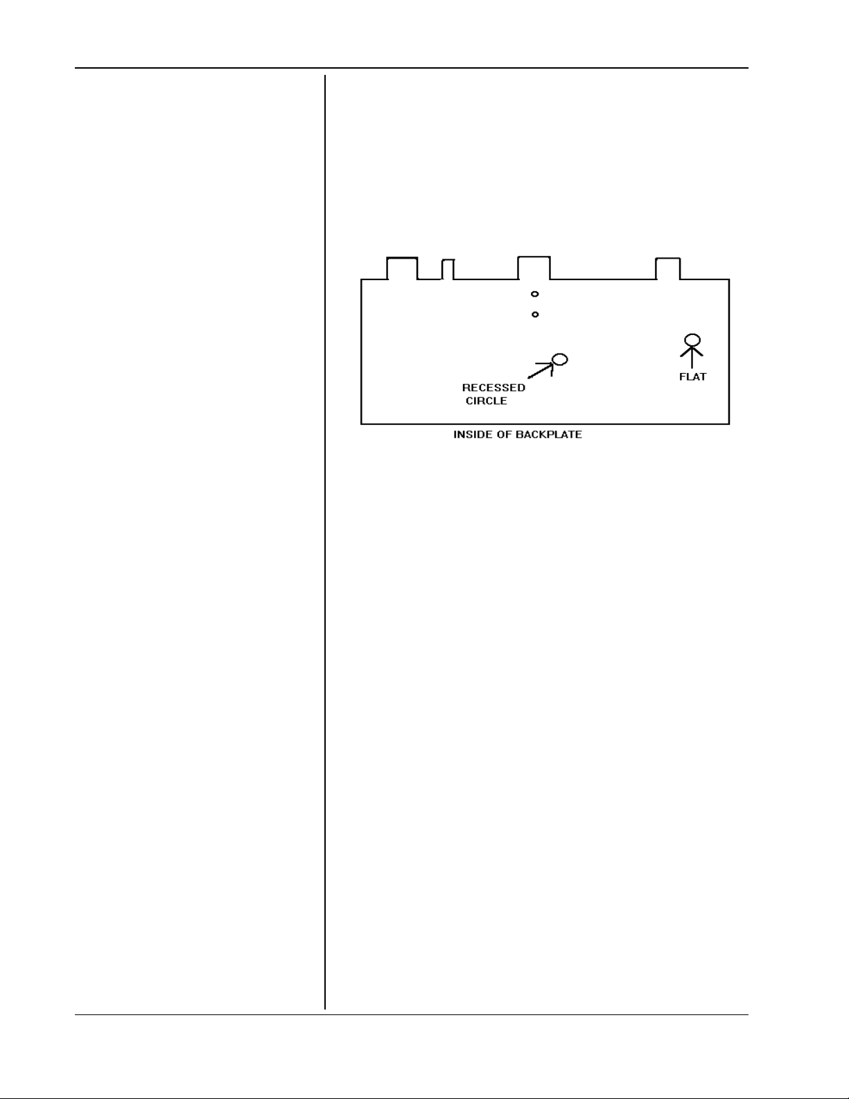
1 Observe backplate; notice what must be
present:
If there is a raised surface where the ‘flat’
should be and/or if there is no recessed circle,
replace backplate (610015-503).Remove
battery holder before discarding old
backplate.
NOTE:Observe back of LCD board. If back of
LCD board does not have a metal bar, you
must replace this board.
2 Apply a moderate amount of force to the side
of each battery contact. Contact should hold
firm. If it does not, take battery contact off and
clean any dried epoxy off of metal conducting
surface on PC board.
Obtain a new battery contact (610067-1) and
solder to PC board, noting proper
positioning.
Before soldering, screw contact onto PC board
with appropriate hardware.
Lastly, tighten to specifications (approx. 12-16
in/oz.) or until moderately firm. Take note that
black fiber washer is not destroyed. Perform
this step whether epoxy was adequate or
contact had to be soldered.
14 Pneumocheck Handle and Printer/Charger Service Manual 610132 Rev. E
Page 16

Section 2 - Service
3 If required, change Red LED to orange
(230015-6).
4 If necessary, change software. You must
remove digital board from front plate to do
this. PROM is location U4 on digital board.
5 If necessary, reverse side contacts. To do this,
remove the two metal contacts from the black
plastic piece. Reverse the plastic piece so that
metal contacts will be raised outside of plastic
surface of main frame. Do this for each side.
6 Calibrate the transducer circuit: to get to ON
reading, see steps 4-7 section A. If ON
reading was in spec.(see step 7, section A),
set to 50 or as close as you can get (within
5 cts.), using R33 (pot at bottom of PC board).
Apply 58.8 DPA (60 mm of water with
manometer) to transducer via long hose.
Adjust R36 (pot just above R33) to 844 +/- 5
cts. Return to ODPA, reading should be 50 +/5 cts. Readjust if necessary.
If the transducer reading is outside of the 30-80
range, measure the transducer output ofpins 2 and 4
of the transducer. They are the two white wires
coming from the transducer. You should see no more
than approx. 300 micro volts (.3mv). If this is the
case, readjust ON reading to spec. as per sec. B,
step 6.
If you see more than 300 mcvolts (.3mv), replace
transducer.
If you cannot build pressure in transducer,
diaphragm is torn, replace transducer.
Service Manual 610132 Rev. E Pneumocheck Handle Printer/Charger 15
Page 17

Section 2 - Service
Once transducer is replaced, calibrate according to
Section B, step 6.
Once transducer is calibrated, re-assemble unit.
7 With unit assembled and good batteries in,
without the pneumotach (top piece), insert
into working printer charger. With a DC
ammeter, measure current between the top
of each battery. You should see approx. 11 ma
recharge current.
If reading is outside of 10-12 ma, refer to
troubleshooting guide.
8 If reading is good, assemble pneumotach onto
handle. Obtain final test form.
Step through, test in ‘DATA’ mode as per
Section A, steps 4-12 .
Observe ‘ON’ reading . As you do this and
write down in appropriate place on form.
Continue to move forward until you see DO
DCV.
At this point throw switch on test printer to RXTX OK
position. This puts a short circuit between the RX and
TX communication lines. Insert handle. The following
messages should appear:
DCV SEEN > RXTX OK > CHARGE > screen blank.
If they do, remove handle, the message DO DCV
should re-appear. Return switch on test printer to RX
fail position.
These tests are taken from spec. A01943 Rev.F.
Get ready to calibrate w/3.0 liter syringe according to
spec. A01945 Rev.D.
16 Pneumocheck Handle and Printer/Charger Service Manual 610132 Rev. E
Page 18
Section 2 - Service
1. ESD protection is required whenever working with the
pneumocheck printer .
2. Apply power to the unit. It should beep twice and the
“power LED” will light. The “data” light should not be
lit.
3. Note and record “dip” switch settings if customer
owned. These switches will have to be returned to
these positions when testing is complete.
4. Check printer well to make sure there is no foam pad.
If there is one, it must be removed. Make sure printer
is powered down. Remove pad by walking and rolling
back pad from ends. Move slowly as to not tear the
pad if possible. Continue until pad is removed. Clean
remaining adhesive with an adhesive remover solution.
Try to avoid scratching the printer well plastic piece.
2.2 Bench Test of the
Pneumocheck Printer/charger
5. Complete the following tests: A .
With a DVM set on the 200VDC range, measure 14vdc
across contacts as shown below that are marked with
an (**).
14 vdc
** ##
gnd
## **
B. Check voltage between ground contact in printer
well and pin 8 of the J2 connector. The J2 connector is
the longer of the two groups of pins in front of the
printhead. Pin 1 is at the left end of the longer group,
counting left to right. The voltage should be between
4.75 and 5.75 vdc.
C. Check voltage between ground contact in printer
well and pin 1 of the J2 connector. The voltage should
be 24vdc +/- .5 volts.
Service Manual 610132 Rev. E Pneumocheck Handle Printer/Charger 17
Page 19

Section 2 - Service
D. Install a paper roll if one is not installed. Measure the
dc voltage between the ground contact in printer well
and pin 3 of the J1 connector . The J1 connector is the
smaller of the two groups of pins in front of the
printhead. Pin 1 is on the left, counting left to right.
The voltage should be 3.00 vdc or less.
6. Making sure the red capped lever at right of printhead
is pushed all the way toward the back of the printer,
hold down the feed button. The paper should advance
steadily forward.
7. Hold down feed button, then press and release the
stop button. The paper should automatically feed in
the reverse direction. Release the feed button. Paper
will stop feeding.
8. Push the print button. The unit should beep,
indicating that it has no data. The data light should
remain unlit.
9. Download data into printer by placing spirometer
handle, in on state, with data in it, into the printer well.
The data light should flash repeatedly for several
seconds. After this, the data light should be lit.
10.Make sure all dip switches on bottom of printer are
set to the “off” position. On top of printer, set the
following: Age: 36; Height: 159; Race: 2; Sex: F .
Depress and release the print button to obtain a
printout. The printout should agree with the settings.
Also, the standard printed should be Knudson 1976
(dip switches 1 and 2 in off position), short form (dip
switch 3 in off position), and the flow over volume graph
(dip switch 4 in off position).
18 Pneumocheck Handle and Printer/Charger Service Manual 610132 Rev. E
Page 20

Section 2 - Service
1 1.Set dip switches on bottom of printer to “on” position.
On top of printer, set the following: Age: 59; Height:
96; Race: 1; Sex: M.
Depress and release the print button to obtain a
printout. Observe printout. The printout should agree
with the settings. Also, the standard should be Euro
CCS (dip switches 1 and 2 in on position), the long
form, which is a questionnaire (dip switch 3 in on
position), and the volume over time graph (dip switch
4 in on position).
12.Return dip switches to position they were when unit
came in from customer. If unit is a loaner , or a new unit
being returned to stock, set all dip switches to off
position.
13.Hold down the print button and press/release the stop
button. Release the print button. A test printout should
print. At right side of top line, check the version of
software. It should be V3.2. If it is V3.1, it needs to be
changed. The “PROM” that controls this is in position
U5 on the main
pcboard. Replace existing Prom with
part number 610102-506. This Prom is software
version V3.2.
14.Perform agency tests on printer. These include the
ground continuity test and the leakage current test. If
the main pcboard, transformer or line filter was
replaced, perform the hypot test. Observe standards.
They are:
Ground continuity test: .2 ohm maximum
resistance with 10 amperes of current flow through the
earth ground line from the wall plug to a distant metal
point on the unit, probably the transformer screw
opposite where the ground wire is connected;
Leakage current test: 100 microamps or less
from any dead metal part on printer to earth ground,
with the printer ungrounded and powered up.
Hypot test: 1200 vac across the hot and neutral
(tied together) and earth ground for one second without
breakdown (voltage reduction).
Service Manual 610132 Rev. E Pneumocheck Handle Printer/Charger 19
Page 21

Section 2 - Service
15.This concludes the printer bench test. Make sure there
is an ample supply of paper in printer. When loading
paper, feed about 2-3 inches, put leading edge of
paper through paper cutter envelope before putting
paper cutter in place. Any questions call Welch Allyn
Technical Service at 800-535-6663, Technical
Support.
20 Pneumocheck Handle and Printer/Charger Service Manual 610132 Rev. E
Page 22

Section 2 - Service
Required Tools:
1. Compression ring tool - Welch Allyn tool
number T8608
2. Snap ring pliers (external) VACO #22
3. #1 Phillips head screwdriver
4. 1/4 inch flat head screwdriver
5. 3/32" Hex Key
Required Test Equipment
1. Merriam M131 Manometer with C34259
mount kit or Welch Allyn Pressure
Applicator Box.
2.3 Tools and Test
Equipment Listing
2. Pressure Source - Welch Allyn number
T9161
3. 0-7VDC Power supply with 100 mA current
limit
4. 0-14VDC Power Supply
5. 0-50mADC ammeter
6. 0-14VDC voltmeter
Service Manual 610132 Rev. E Pneumocheck Handle Printer/Charger 21
Page 23

Section 2 - Service
2.4 TEST AND
ADJUSTMENTS
PNEUMOCHECK HANDLE
A set of specification drawings have been included in
Section 7 with reference made to them here. The
following tests should be done before the unit is
returned to the customer.
1 Calibrate and test the handle per specification
drawing A01945. “Calibrating with Welch Allyn
Spirometer.
2. Perform all tests on specification drawing
A01951, “Dynamic Waveform Testing”
For troubleshooting use, specification drawing
A01943 has been included for testing at the
PC Board Level.
PNEUMOCHECK PRINTER/
CHARGER
22 Pneumocheck Handle and Printer/Charger Service Manual 610132 Rev. E
1. Perform Dielectric Strength Test per:
A00167- UL/CSA Models
A00178- IEC Models
2. Perform Leakage Current Test per A00171
3. Perform Grounding Continuity Test per:
A00172 - UL/CSA
A02242 - IEC
4. Perform all tests listed on A01958, “Base Final
Testing”
For troubleshooting use, specification drawing
A01946 has been included for testing at the PC
Board Level.
Page 24

Section 3 - Theory of Operation
3.1 Spirometer Circuit Description
3.2 Spirometer - Printer Circuit Description
3.3 Messages
Theory of Operation
Service Manual 610132 Rev. E Pneumocheck Handle Printer/Charger 23
Page 25

Section 3 - Theory of Operation
3.1 Spirometer Circuit Description
General
The handheld spirometer’s electronics are contained on
two boards, designated the “Digital Board” and the
“Analog Board”. The analog board contains the power
control circuitry, as well as the analog signal amplifiers.
The digital board contains the digital circuitry, as well as
the front panel components.
The spirometer is designed to minimize power
consumption by having four separate operational
states:
a. OFF When SW1 is off only the battery charge
circuit is enabled. Only diode leakage
current flows.
b. ASLEEP In this state SW1 is on and Vcc is
present but the processor is not running. The
switched analog power is off.
In this state:
i. CR1 is not oscillating
ii. RB is oscillating (100Khz)
iii. All port bits are tri-state except for P6
which has all bits low
iv. The data and address bus is passive
v. The RAM is disabled (U5 pin 26 is low)
vi. TP6 is low
Normally in this state, since the LCD controller is
running, there will be something on the display. The
software can, however, intentionally blank the display.
c. AWAKE In this state the digital circuitry is
operating, but the analog power is off. This
state is entered when the processor has some
work to do.
24 Pneumocheck Handle and Printer/Charger Service Manual 610132 Rev. E
Page 26

Section 3 - Theory of Operation
In this state:
i. VA+ and VA- are not present
ii. U12 and U13 are not powered
iii. U8 i s not operating
iv . CR1 is oscillating (8Mhz)
v . The CPU clock (pin 22 of U4) is running
(2Mhz)
In normal operation this state will terminate and
return to the sleep state as soon as the p ro ce ss or
has nothing to do, such as while it is waiting for a
keypress.
d. FULL ON In this state all of the circuitry is turned
on. The charge pump may or may not
be operating.
If everything is correct the power consumption in the
four states should be:
State 1: OFF: Less that 0.1ma, typ 0.001ma
State 2: ASLEEP: Less than 2.5ma, typ 1.6 ma
State 3: AWAKE: Less than 16ma, typ 10ma
State 4: FULL ON: Less than 35ma, typ 25ma
NOTE: That achieving these levels is both a hardware
and a software function. Malfunctioning software can
raise the power to as much as 5ma in State 2 and 70ma
in State 4.
The maintenance mode of the spirometer allows it to be
placed in each state for testing purposes.
2. Power Consumption
Service Manual 610132 Rev. E Pneumocheck Handle Printer/Charger 25
Page 27

Section 3 - Theory of Operation
3. Spirometer Power
Circuit Description
The battery charge is supplied by U14 which is a voltage
regulator wired as a 12ma current source. D6 and D7
provide reverse polarity protection.
Transistor T1 is the source for the current used in the
spirometer if it is turned on while plugged into the
printer. Its output voltage is regulated by the zener D13
to a voltage which will reverse bias D18 while at the
same time insuring that the voltage reaching U8 does
not exceed its design limit of 10v. This means that the
tested voltage at TP1 must lie between 7.7 and 9.6v
with 14-20v applied to the DC jack.
R22 and R23 divide the zener voltage to provide the
sense voltage so that the processor can tell when DC is
applied. This voltage should be between 4.20 and 4.85
volts with DC applied to the charging jack. This sense
voltage is taken to pin 35 of the CPU and pin 1 of the U1.
The raw power for the spirometer comes from either the
battery via D18, or if DC is supplied, via T1. It goes
through the ON/OFF switch SW1 to the 5v regulator
119. U9 also supplies the low battery warning if Vcc
comes out of regulation. This will occur when the
battery voltage drops below about 6.3 volts.
Power for the analog sampling circuitry is taken directly
from the battery so that it is impossible to test patients
while powering the unit from the DC jack. T5 and T6
form a software controlled switch to turn analog power
on only while actually needed and thus conserve
battery power. This voltage will be on when CPU pin 2
is high. The voltage at the collector of T6 will be 6 to 10
volts when on, and can be easily tested at pin 1 or U1.
This switched analog voltage is inverted by U8, which
should have a visible charge pump oscillating at eight
kilohertz across C18. It will develop at least -6 volts
across C20.
The switched analog voltage and its inversion are
regulated by U7, T3, and T4 to provide +/- 4 volts VA+
and VA-. R18 and R19 divide Vcc to provide a guide
voltage. U7A and T3 use this voltage to give VA+. U7B
and T4 invert VA+ to provide a matching VA-.
26 Pneumocheck Handle and Printer/Charger Service Manual 610132 Rev. E
Page 28

Section 3 - Theory of Operation
TP2 and TP3 should measure +/- 3.90 to 4.10 volts. These
voltages power the pressure transducer as well a U10 to
U11.
The switched analog voltage is also, regulated by U15B
and T2 to give an isolated 5v +/- 0.10 volts at TP6. This
voltage powers the A/D and U12. Under the assumption
that both devices will never be used at the same instant,
this power is also used to supply U13 on units with a
610117-501 pressure transducers. Units with a
6010116-501 use Vcc.
Since the reference voltage from the A/D and the
reference voltage of the transducer are both derived
from Vcc, any variations in Vcc are ratiometrically
canceled out.
U10 and U11 are powered by VA+ and VA- because
they must deal with negative voltages. However, since
VA+ is less than Vcc, they cannot swing the full voltage
range of the A/D. Therefore, U15, the first amplifier
stage, is powered by V+.
When pressure sensing, VA+ and VA- must be on. The
output of the transducer is a small differential signal
(0.45 to 0.9 mv/cm H2O) on a common mode signal of
about -1 volts.
U10 forms a differential amplifier with adjustable gain.
U11B removes the common mode voltage, provides an
appropriate level shift, and provides a further gain of 5x.
The output of U11B is frequency limited to a few
hundred hertz by C25.
The bais voltage is supplied by a software charge
pump. When appropriate software is running 0-1 Khz
pulse train from pin 16 of the CPU charges C2 to 0-2
volts (TP4). U11A buffers this voltage and uses it to
offset U11B.
4. Spirometer Analog
Circuit Description
Service Manual 610132 Rev. E Pneumocheck Handle Printer/Charger 27
Page 29

Section 3 - Theory of Operation
The output of U11B (TP5) depends upon the particular
transducer, the charge pump and the adjustment of R33
and R36. The nominal output is 0.125 volt with no
pressure applied and 2.10 volts with a pressure
corresponding to 12 L/S of airflow (approximately 6cm
H2O). With no pressure and no charge pump pulse train
TP5 will be in the neighborhood of 1 volt.
U15A provides the final stage of amplification (2x). D9
clamps its input to prevent latch up when the output of
U11B goes negative.
With VA on, the charge pump operating and R33 and
R36 adjusted. U15A drives the A/D channel 0 with 0.5
- 4.5 volts as the airflow in the sensor ranges from 0 to
14 L/S.
5. Spirometer Digital
Circuit Description
The CPU, U2, has an address and data bus which
connects it to a 32K RAM U4, and 8K RAM, U5. Control
for these is performed by U3.
D1 and C4 provide a power-on reset. Residual power is
quickly discharged through SW1 and R3 to ensure that
reset occurs every time the power is cycled.
The A/D, EEPROM and LCD controller (U6) are serial
devices connected to the CPU ports.
The “TEST” key is connected directly to a CPU interrupt
input. The other interrupt input is shared by the “DATA”
key and the DC sense line from the power supply.
In order to allow both positive and negative transitions
of DC input to cause interrupts. U1B can be used to
invert the DC sense signal under software control. U1A
forms a latch which can be forced high or low by
software. R2 keeps it latched which can be forced high
or low by the software. R2 keeps latched high or low
when the CPU goes to sleep and the P4,4 goes to the
tri-state condition.
28 Pneumocheck Handle and Printer/Charger Service Manual 610132 Rev. E
Page 30

Section 3 - Theory of Operation
First, there is a signal from pin 5 of U9 which will go low
if Vcc comes out of regulation. This will occur if the
battery voltage falls below about 6.3 volts, depending
on the load.
In normal operation Vcc coming out of regulation will be
detected as soon as a key is pressed and the CPU
wakes up again. No detection is made while the unit is
waiting for a key press because the CPU is ASLEEP.
Another situation which can occur is that the battery is
failing but Vcc has not yet come out of regulation. This
condition is determined by software control of T7,
which, when ON, couples VA+ into A/D converter
channel 1. This allows VA+ to be compared to Vref =
Vcc, from which it is possible to detect a failing battery.
This case is only detected when the spirometer enters
the “STEADY” phase at the start of a test. This
condition occurs when the battery voltage falls below
about 6.2 volts.
6. Low Battery Detection
Note that the latter form of low battery condition is
“temporary”, because when it is detected the “LOW
BAT” warning is given and analog power is turned back
off again. If Vcc is still good the “LOW BAT” message
goes away again after several seconds and the unit
returns to “SELECT”.
A unit in this condition cannot perform further tests, but
it can retain, review, and transmit an existing test.
Due to the sharp decay rate of NI-CAD batteries, this
interim state will exist for only a short time. Before long,
Vcc will come out of regulation and the “LOW BAT”
condition will become permanent.
The operation of the low battery detection can be tested
in maintenance mode by varying the voltage applied to
the battery terminals while operating the unit.
Service Manual 610132 Rev. E Pneumocheck Handle Printer/Charger 29
Page 31

Section 3 - Theory of Operation
3.2 Spirometer - Printer
Circuit Description
1. Digital Circuit Desription
This board is based on the Mitsubishi 50734 processor
which has an integral stepping motor driver, a UART
and a four channel 8 bit A/D converter. This makes the
digital circuitry very simple.
The printer mechanism has the thermal head driver
internal to it, so the interface to the processor is simple
and direct. The head temperature must be monitored
by the processor so that the head pulse width can be
controlled to produce a consistent end image at any
temperature. In this circuit the head thermistor is
balanced against an adjustable resistor which allows us
to trim each unit for variations in the head and
thermistor without trimming the timing constants within
the software. The software is designed to prevent
driving the head when the thermistor reading is out of
range. By using other analog channels for “Head-up”
and “Papersense” we avoid the need for logic level
converters on these lines.
The printer mechanism prints 256 dots per line in four
distinct banks of 64 dots. The signals DST1 through
DST4 select the bank. The data for each bank is loaded
serially from the processor using the CLK, DIN, and
LATCH signals. The ENABLE signal protects the
element heaters during CPU reset cycles.
In order to achieve maximum printing speed, the
printing actually occurs while the paper is moving
smoothly. Thus the printed horizontal lines are actually
less diagonal.
The UDS 5707 serves to buffer the paper drive motor
signals. D12 clamps the inductive surges. A port bit is
used to disable the motor drivers when they are not
being used. CPU pin 22 must be high to enable the
motor. On newer boards this buffer is an SN 75437
(P/N 761181-501), and performs the same function.
The front panel is a simple matrix of switch closures
isolated with doides. The options DIP switch is handled
in the same way.
30 Pneumocheck Handle and Printer/Charger Service Manual 610132 Rev. E
Page 32

Section 3 - Theory of Operation
The two inverters connected to the CPU pin 23
functions as a latch which powers up in the low state but
which can be forced to a latched high state by software.
It is used to provide a reliable mechanism by which the
software can distinguish between power-up reset and a
reset caused by the front panel reset key.
The three inverters connected to CPU pin 20 provide
enough drive to illuminate the front panel “ready” LED
directly.
The alarm device is an electromagnetic transducer. It
requires a transistor to drive it. D1 clamps inductive
surges.
Communication with the spirometer is handled by
protected direct UART connections. The signals are
standard asynchronous ASCII at 4800 baud, however,
the levels are CMOS logic levels, not RS232 level.
The printer power supply provides 24 volts at 3 amps
peak. 5 volts at 200ma, and 14 volts at 100ma.
The 24 volts output is regulated with a switching power
regulator while the 5 and 14 volt supplies utilitize linear
regulators. The present design incorporates a
transformer that allows a primary voltage of either 90 to
132 vac or 200 to 275 vac.
The switching regulator IC has a maximum allowable
supply voltage of 50 volts. The minimum output voltage
for the 24 volt supply that will ensure proper printer
operation and print contrast is 22 volts. Using a
transformer with a nominal 25 volt secondary and a full
wave bridge rectifier result in a voltage range of 27 volts
to 43 volts at the regulator when the input voltage varies
through the specified range.
The switching oscillator frequency is determined C17
and R32 which were selected to provide a 20Kh rate.
2. Printer Power Supply
Circuit Description
Service Manual 610132 Rev. E Pneumocheck Handle Printer/Charger 31
Page 33

Section 3 - Theory of Operation
The 24 volt output is fed into a divider network made up
of R27 and R28. The output of the divider network is
then fed into the error amplifier, ERR1. The 5 volt
reference voltage is reduced through a divider made up
of R37, R38, and R39 to 2 volts, and also fed into ERR1.
The difference voltage is then used to correct the 24 volt
output voltage.
The output current is limited to 2.5A by comparing the
voltage across R29 and to the 0.5 volt output of the
reference divider network.
A soft start circuit made up of C18, R31, and R38
causes the regulator to wait about 50 clock cycles
before the transistor control pulse width is increased to
its normal duration.
32 Pneumocheck Handle and Printer/Charger Service Manual 610132 Rev. E
Page 34

Section 3 - Theory of Operation
3.3 Messages
The following is a tabulation of the various messages
that may be displayed by the spirometer and/or printer
by the printer:
Indicates that this test has a greater FVC+FEV1 than
the one currently in memory. It will replace the stored
test.
Indicates that this test is close to but not better than, the
currently stored best test.
Indicates that this test has a lower FVC or FEV1 by at
least 5%, and will not replace the existing best test. To
correct this, inhale more fully before blowing, and blast
out harder at the start.
The effort was good. (A “good” test is one with no
identifiable faults.)
The patient coughed during the maneuver or flow was
interrupted, or uneven. To correct this, the patient
should refrain from coughing.
Quality Messages
NEW BEST
MATCH
NO MATCH
GOOD FVC
COUGH
5% or 0.1 liters of exhalation occurs before the back
extrapolation point. (ATS specification.) To correct this
the patient should blast out harder at the beginning of
the maneuver.
The flow stopped abruptly. To correct this. The patient
should keep blowing longer.
Low flow effort. To correct this, the patient should blast
out harder.
The maneuver was less the 3 seconds long. To correct
this, the patient should inhale more deeply and blow
out longer. If this message is displayed during an MVV
maneuver, the maneuver was less than 6 seconds long,
and the patient should continue longer.
The effort was good.
BAD. START
BAD.STOP
WEAK TRY
TOO.SHORT
GOOD MVV
Service Manual 610132 Rev. E Pneumocheck Handle Printer/Charger 33
Page 35

Section 3 - Theory of Operation
GOOD CAL
CF=XXX
RETRY.CAL
Each of the 3 calibration maneuvers was within 1/2% of
the average. The existing calibration factor will be
replaced with the cal factor from this calibration.
Shows calibration value after a successful calibration
was completed. The value is now the new calibration
value replacing the old one that was previously stored
in memory.
One or more of the calibration maneuvers exceeded
the average by more that 1/2%. The existing calibration
factor is not updated.
Test Values
FVC x.xxx In Liters
FEV1 x.xxx In Liters
RATIO xx % FEV1/FVC
Status Messages
CLEAR
TEST.MODE
SEND FVC
MMEF x.xxx In liters per second
PEF x.xxx In liters per second
MVV xxx In liters per minute
RATE xxx In liters per minute
TIME xx.x In seconds
Appears when the power is recycled, indicating that the
memory is cleared.
Appears briefly when entering the test mode of the
device.
Indicates that the spirometer is transmitting an FVC test
to the printer base.
SEND MVV
34 Pneumocheck Handle and Printer/Charger Service Manual 610132 Rev. E
Indicates that the spirometer is transmitting an MVV
test to the printer base.
Page 36

Section 3 - Theory of Operation
Indicates that the device has begun charging the
spirometer batteries.
Asks the operator or patient to hold the spirometer
steady (with no movement) while it references the
machine to zero flow in order to establish a baseline for
future data.
Indicates that the spirometer is in the process of
readjusting the nominal charge pump value for zero
flow.
Appears briefly while the spirometer calculating the
results of a test.
Appears when the operator pushes the TEST key from
the ready position. If the operator does not push the
TEST key again within 2 seconds, the spirometer will
conclude that an MVV test is desired, and will begin the
MVV sequence.
CHARGE
STEADY
RETRIM
BUSY
FVC
Appears if the operator presses the TEST key again
within 2 seconds, the spirometer will conclude that an
MVV test is desired, and will begin the MVV sequence.
Appears if the operator presses the TEST key
immediately after the MVV message is displayed.
Once this message is displayed, if the operator does
not press the TEST key again within 2 seconds, the
spirometer will conclude that a calibration is desired,
and will begin the calibration sequence.
If the operator presses the TEST key immediately after
the CAL message, the spirometer will go back to
READY.
Asks the patient to perform the nth FVC maneuver.
Tests are numbered, so that you can see which test you
are on.
Asks the patient to perform the nth MVV maneuver.
MVV
CAL
DO FVC n
DO MVV n
Asks the patient to perform the nth calibration
maneuver.
Service Manual 610132 Rev. E Pneumocheck Handle Printer/Charger 35
DO CAL n
Page 37

Section 3 - Theory of Operation
Exception Messages
FLOW LIM
VOL LIM
TOO SOON
TX FAIL
NO DATA A
NO DATA B
NO DATA C
NO DATA D
The flow during a maneuver has exceeded the flow
sensor’s capacity of 14 liters/second (minimum).
The volume during a maneuver has exceeded the
spirometers capacity of liters (minimum).
Flow was present as a sampling started.
Transmission failure.
Maneuver was interrupted, such as by the press of a
key or the detection of a low battery.
FVC or MVV timed out - the maneuver did not start
within 13 seconds after the beep.
FVC terminated normally, but on analysis, no
exhalation was found.
The FVC maneuver appeared too short and/or
fragmented; possibly coughing with no blow.
NO DATA E
NO DATA F
NO DATA G
Problem and Error Messages
LOW BATT
TEMP LIM
The MVV did not have enough breaths to analyze.
During the MVV, the breaths were too inconsistent or
uneven.
Maneuver analysis routine failed: unable to analyze the
data.
The battery is too low to continue and requires
recharging.
The temperature range of the spirometer has been
exceeded. The acceptable operating range is between
59 and 105
o
F. The spirometer must be allowed to
return to an acceptable temperature range before
continuing.
36 Pneumocheck Handle and Printer/Charger Service Manual 610132 Rev. E
Page 38

Section 3 - Theory of Operation
The device cannot trim the baseline out. This is usually
due to an abrupt thermal change. The machine must
be allowed to return to an acceptable temperature
range before proceeding.
Encountering either the TEMP LIM or TRIM LIM
messages during normal operation may indicate a
possible hardware failure.
The spirometer failed to see a stable baseline value
within 30 seconds.
Bus error.
EEPROM check sum error. (This will occur once upon
first use of a new machine).
TRIM LIM
UNSTEADY
ERROR 0
ERROR 1
Out of memory.
Opcode error--another form of bus error.
Interrupt timing error.
EEPROM failure.
Spurious interrupt.
Error numbers greater that these indicate an
unexpected event in the program. In general, error
messages are probably caused by a hardware failure.
ERROR 2
ERROR 3
ERROR 4
ERROR 5
ERROR 6
Service Manual 610132 Rev. E Pneumocheck Handle Printer/Charger 37
Page 39

38 Pneumocheck Handle and Printer/Charger Service Manual 610132 Rev. E
Page 40

Section 4 - Troubleshooting
T roubleshooting
4.1 Technical Troubleshooting
4.2 Customer Service Questions and Answers
Service Manual 610132 Rev. E Pneumocheck Handle and Printer/Charger 39
Page 41

Section 4 - Troubleshooting
4.1 PneumoCheck Handle Technical Troubleshooting
(Most frequent problems at top)
tnialpmoCesuaCnoitcAevitcerroC
ydaetsnusdaeR.1recudsnartevitcefeD)ArecudsnartecalpeR)A
sdaeR.2 'BATADON' recudsnartevitcefeD)ArecudsnartecalpeR)A
)liafxT(timsnarttonseoD.3noitisoptcatnocedisgnorW)A.stcatnocnoitisopeR)A
sdaeR.4 'TABWOL' seirettabdeliaF)Aseirettabecalper/tseT)A
Model Number: 61001
rotaluger667evitcefeD)Brotaluger667ecalpeR)B
eriwrecudsnartnekorB)CsnoitcenocerotseR)C
eriwrecudsnartnekorB)BsnoitcennocerotseR)B
stcatnocytriD)BstcatnocnaelC)B
eldnahnieriwnekorB)CsnoitcennocerotseR)C
stcatnoc/yrettabdedorroC)BsmetidedorrocecalpeR)B
tnenopmocevitcefeD)C
6PTtaegatlovon
purewoptonlliW.5
)ezigrene(egatlovyrettabwoL)Aseirettabecalper/tseT)A
stcatnocyrettabdedorroC)BsmetidedorrocecalpeR)B
hcatomuenPdedorroc/ytriD)C
stcatnoc
81DdeliaF)D81DecalpeR)D
hctiwSffO/nOdeliaF)EhctiwSffO/nOecalpeR)E
5rorresdaeR.6egatlovyrettabwoL)A
rotcennoc1JtatniojredlosdloC)B
draoblatigid
elbacnobbirdeliaF)CelbacnobbirecalpeR)C
rossecorPnotniojredlosdloC)D rossecorPnotniojredloserotseR)D
CDA21UdeliaF)ECDA21UecalpeR)E
.21Uro,81D,8UecalpeR)C
.stniojredlosdlocrofkcehC
stniojerotseR
.stcatnocytridnaelC)C
stcatnocdedorrocecalpeR
.yrettabegrahceR)A
yrettabevitcefedecalpeR
tniojredloserotseR)B
52rorresdaeR.7erawtfosdlO)AerawtfoswenotedargpU)A
rosnes.pmetdeliaF)Brosnes.pmetecalpeR)B
.pmettneibmahgiH)C
nwod
tinuloocdnamoorreloocotevoM)C
40 Pneumocheck Handle and Printer/Charger Service Manual 610132 Rev. E
Page 42

Section 4 -Troubleshooting
PneumoCheck Handle Technical Troubleshooting
tnialpmoCesuaCnoitcAevitcerroC
Model Number: 61001
sdaeR.8 'MILPMET'
)erawtfosweN(
rorresdaeR.9 '1' MORPE31UdeliaF)AMORPE31UecalpeR)A
rorresdaeR.01 53 morpdeliaF)AmorpdemmargorpecalpeR)A
tuostnemgeS.11DCLnOelytsdlO)A
sdaeR.21 'LACYRTER' recudsnartdeliaF)ArecudsnartecalpeR)A
gnidaernoelbatsnU.31
etarbilactonlliW
tsetegrahcersliaF.41retnirpnidetaestontinU)AeldnahtaeserdnaevomeR)A
egatlovysioN)A
7DevitcefeD)C7DecalpeR)C
rosnes.pmetdeliaF)Arosnes.pmetecalpeR)A
)s(tcatnocDCLytriD)B)s(tcatnocDCLnaelC)B
hcatomuenPdeliaF)BhcatomuenpecalpeR)B
esoheceiphtuomesooL)CesohnethgiT)C
)4-ro/dna4+(
redlosrosroticapacdeliaF)BsnoitcennocerotserkcehC)B
81DevitcefeD)B81DecalpeR)B
latigidBCPlatigidecalpeR)A
draob
,51C,41C,21CsroticapackcehC)A
02C,91C
41UevitcefeD)D713ML41UecalpeR)D
Service Manual 610132 Rev. E Pneumocheck Handle and Printer/Charger 41
Page 43

Section 4 -Troubleshooting
PneumoCheck Printer T roubleshooting
(Most frequent problems at top)
melborPesuaCnoitcAevitcerroC
esufnwolB.1)s(esufnepo,egruseniL)A)s(esufecalpeR)A
Model(s): 76101
egatlovgnihctiwS.7UdetrohS)B
1-990167,rotaluger
roticapac71CdetrohS)C
)v05fu2.2(
repapecnavdatonseoD.2noitcesrotomdaehtnirpdeliaF)AdaehtnirpecalpeR)A
elbacnobbir1JevitcefeD)B1JecalperroriapeR)B
ylppusv42+woL)C
revird6UdeliaF)Drevird6UecalpeR)D
)ezigrene(purewoptonlliW.3)s(esufnepO)A)s(esufecalpeR)A
rotaluger7UdeliaF)Brotaluger7UecalpeR)B
4PtaeriwnopmircesooL)C
rotcennoc
tuotnirpetelpmocnirodaB.4580167NPdaehtnirpdeliaF)AdaehtnirpecalpeR)A
elbacnobbir2JdeliaF)Belbacnobbir2JecalpeR)B
tatniojredlos1VdloC)C
rossecorp
rotaluger7UecalpeR)B
roticapac71CecalpeR)C
detaicossarehtoro/dna7UecalpeR)C
trapdeliaf
4PtaeriwpmirceR)C
tniojredlosriapeR)C
rossecorp1UdeliaF)Drossecorp1UecalpeR)D
putratsnolangis"peeB"oN.54U,3U,1UtatniojdaB)AtniojredlosdlocriapeR)A
605-201016morp5UdeliaF)Bmorp5UecalpeR)B
daehtnirpdetrohS)CdaehtnirpecalpeR)C
latsyrc1RCdeliaF)Dlatsyrc1RCecalpeR)D
/egareporptnirptonseoD.6
tamrofthgieh
/ecarreporptnirptonseoD.7
tamrofxes
snoitporeporptnirptonseoD.8
)1ws(tamrof
draob
draob
sedoiddetaicossa
hctiwsyratornoedoiddeliaF)B
bcplortnocnotniojredlosdloC)AtniojredlosriapeR)A
bcplortnocnoedoiddeliaF)BedoiddeliafecalpeR)B
ro1wstatniojredlosdloC)A
edoiddetaicossaro1wsdeliaF)Bedoiddetaicossaro1wsecalpeR)B
hctiwsyratornotniojredlosdloC)A
tniojredlosriapeR)A
edoiddeliafecalpeR)B
)s(tniojredlosdlocriapeR)A
42 Pneumocheck Handle and Printer/Charger Service Manual 610132 Rev. E
Page 44

Section 4 -Troubleshooting
Solutions
4.2 Customer Service
Questions and Answers
Reading On LCD
Make sure they are not attempting to calibrate while
the handle is in the printer well.
Make sure they realize there is a CALIBRATION
CHECK and a RECALIBRATION. When performing
calibration, 3 liter syringe must be operated smoothly
and evenly with consistent speed. Refer to pages
32, 33, 34, & 35 of operating instructions for the
calibration instruction.
The American Thoracic Society recommends
checking accurancy of calibration daily.
If documentation of the calibration check is required,
insert the handle in the printer well and push print
after a cal check had been completed. (Note: They
cannot get a printout of the recalibration).
The pneumotach screen should be inspected daily
and cleaned when necessary.
Calibration
Cleaning & Sterilizing
We recommend cleaning and sterilizing the
pneumotach assembly every 50 maneuvers. They
can be steam autoclaved, ethylene oxide, soaked or
boiled.
Regardless of sterilization method, pneumotach
must be completely dry before reusing. A wet or
damp pneumotach inaccurate results. Four days air
drying time is required, or 10 minutes with a hair
dryer on high.
Handle must come back for repair.
The handle must come back for checking and repair.
Turn the unit off, then on again. It may reset itself. If
not, it is a hadware problem-handle must come back
for service.
Display Blank (Or Fading)
Erroneous Results
Error 5
Service Manual 610132 Rev. E Pneumocheck Handle Printer/Charger 43
Page 45

Section 4 -Troubleshooting
Error 23
Error 25 Or Temp. Lim
Infrequently customer complains of Error 23. Have
them turn handle off/on to see if it will reset-perhaps
leave for a couple minutes and try again. In talking
the Tech. Rep., they have not been able to duplicate
problem inhouse. Customer must return both
handle and printer for service.
This is a temperature problem.
Is the office extra warm (cold) today?
Is the unit sitting in direct sun, near heat register,
etc.?
Advise to put the handle on the desk for a minute
before attempting a test - it should be OK.
If the error message continues and creates a problem
they may return handle for new software update (3.5)
It was also discovered Error 25 could indicate low
battery. Change batteries.
Forced Vital Capacity
Getting the Wrong Graph
Green Data Light on Printer
The amount of air that can be exhaled during a rapid
forced exhalation. (1 long, hard blast)
Have them check the bottom of the printer, “flip” the
4th switch the opposite way, and see it that corrects
the situation.
This indicator light will be lit as long as there is
information on the printer.
If they want to clear the printer entirely, it must be
unplugged.
If the customer has entered incorrect data in the
height or age, and the patient data is still in the
printer, all they need to do is insert correct info and
push print.
44 Pneumocheck Handle and Printer/Charger Service Manual 610132 Rev. E
Page 46

Section 4 -Troubleshooting
Are batteries within warranty? Check battery voltage
should be 3.5 volts.
Are the printer & handle power lights (orange) on?
Put in charger overnight, try again. Has it been in the
printer charger?
If error 5 appears after unit has been in printer for
more than 3 hours, let unit cool down. If error 5 goes
away, there is a hardware failure, unit must be
returned.
Make sure the contacts in the pneumocheck
assembly are making good contact with the batteries.
Clean contacts.
If necessary, return handle & printer for checking.
The largest column of air inhaled and/or exhaled over
a timed period. This maneuver imitates rapid
breathing.
Low Batt Message
Maximum V oluntary
Ventilation
The maneuver did not start within 20 seconds after
the “beep”.
Have them try again, watching the display carefully.
If a problem, return handle.
The problem is due to the information the user
entered into the printer:
The AGE of the individual is outside the limits built into
the predicted values (for Knudson 3, the limits are age 5
to 83 for males and 87 for females). These can be found
on Pages 54 through 58 of the operating instructions.
Pages 52 & 53 of the operating instructions gives the
formula for calculating predicted values manually .
Or the HEIGHTis entered wrong. You can use either
inches or centimeters, and in using inches the “O” must
go in the first space. Example: Patient is 5 foot 6 inches
tall. Info entered into machine: 066
No DATA B
No % Or Norms on Printout
Page 54 in Operating Instructions
Service Manual 610132 Rev. E Pneumocheck Handle Printer/Charger 45
Page 47

Section 4 -Troubleshooting
No % Or Norms on Printout
Page 54 in Operating Instructions
cont’d
No Power to Printer
No Print on Printout
Paper Replacement
Pneumocheck handle is in test mode-you will
received no % norms in the print-Turn on w/out
buttons depressed. Remove handle-turn unit off turn
handle on into normal mode.
They may have blown a fuse.
Make sure the paper is inserted correctly.
If cannot be corrected, printer must be returned for
service.
Remove printer cover.
Feed any remaining paper through printer. DO NOT
PULL PAPER BACKWARDS THROUGH THE
PRINGER.
Save black plastic spindle.
The printer does not store
more than one patients Data
The printer saves only the
best test.
Put red lever all the way forward.
Place new roll of paper in the printer well. The paper
feeds forward from the bottom of the roll.
Insert edge of paper under the gray rubber pinch
roller until paper exits top of printer.
Push red lever as far back as possible.
Press FEED button to feed paper through.
Replace printer cover.
If the doctor wants a printout of all the tests on a
patient, they have to run a test, print it out, then turn
off the Pneumocheck and start over again as a new
test.
THE PNEUMOCHECK HANDLE SHOULD BE LEFT
IN THE OFF POSITION TO KEEP THE BATTERY
FULLY CHARGED AT ALL TIMES. THE PRINTER
SHOULD BE LEFT PLUGGED IN.
46 Pneumocheck Handle and Printer/Charger Service Manual 610132 Rev. E
Page 48

Section 4 -Troubleshooting
On the bottom right hand corner of the printer, there
are 4 little dip switches.
1 & 2 control the predicted
3 indicates long or short form
4 indicates volume/time or flow/volume graph.
Refer to page 24 of operating instructions.
When the machines leave the factory, they are set
with all the switches in the off position, i.e., they are
set for the Knudson 83 predicted values, short form,
and flow/volume graph.
The norms that are selected, together with the
version of software in the machine print out on each
tape. This is located just below the actual values.
Example: NORMS: KNUDSON 1983 (VS35P31)
(The “S” means handle, “P” means printer)
Printer Options
The message “Retrim” in itself is no problem. They
MUST let the unit work thru this step. If they turn it
off, they will only get retrim the next time they go to do
a test. The retrim mode lasts 45 seconds to 1 minute,
then it will advance to “do FVC”. (Sometimes I have
found it necessary to have the customer get the
instrument into “retrim” mode and time with a watch.
It may seem like an eternity, but actually will be
within the 1 minute range).
Retrim only means the instrument is trying to
establish the baseline. It will not go into this mode
each time they want to do a procedure.
If retrim occurs regularly, or if it will not advance after
the 1 minute, handle must be returned for service.
The Welch Allyn PnuemoCheck complies with
American Thoracic Society
OSHA
UL
CSA
IEC
Retrim
Standards Compliance
Service Manual 610132 Rev. E Pneumocheck Handle Printer/Charger 47
Page 49

Section 4 -Troubleshooting
T rim.Lim
TX Fail (Transmission Fails)
Handle cannot trim the baseline. May be due to an
abrupt thermal change or weak battery.
If not, may be hardware failure. If so, turn handle off/on.
If unit does not clear, return for service.
Broken or bent contact in handle or printer? Push
paper feed button - Does paper feed through
machine.
If not: Is there paper in the machine?
Is paper tension lever (red, near paper roll) pushed
back all the way? Make sure that paper is properly
fed. There could be a paper jam.
To clear: Depress STOP & FEED buttons
simultaniously. Release STOP button. This will feed
paper backwards. Release FEED button. This should
clear the jam. Depress FEED button - paper should
flow through OK.
Printer does not advance paper and/or unit grinds
or strains when the feed button is depressed.
As a “last ditch” effort, unplug the printer ar the back
and plug it in again - this should reset the machine.
Unsteady
48 Pneumocheck Handle and Printer/Charger Service Manual 610132 Rev. E
While in the “steady” mode, was the handle moved?
If not, problem could be a bad tranducer - handle
must be returned for repair.
Page 50

Section 5 - Disassembly and Repair
Disassembly and Repair
5.1 Pneumocheck Handle
5.2 Pneumocheck Printer/Charger
Service Manual 610132 Rev. E Pneumocheck Handle Printer/Charger 49
Page 51

Section 5 - Disassembly and Repair
5.1 PNEUMOCHECK
HANDLE DISASSEMBLY
PROCEDURES
ITEM NUMBERS REFERENCED ON DRAWING
610135 (SPIROMETER ASSEMBLY)
This section describes how to remove the following
subassemblies and major components:
A. MOUTH PIECE ASSEMBLY (Item 3)
B. PNEUMOTACH ASSEMBLY (Item 18)
C. REAR BASE ASSEMBLY (Item 2)
D. ELECTRONIC COMPONENT
ASSEMBLY (Item 6)
E. FRONT HOUSING ASSEMBLY (Item
21)
F. BATTERY CONTACTS (P/N 610067)
G. PRESSURE TRANSDUCER
ASSEMBLY (P/N 610116-502)
NOTE: All work must be done at a grounded work
station by grounded personnel.
A. Removing the MOUTH PIECE ASSEMBLY
(Item 3)
1. Remove the MOUTH PIECE
ASSEMBLY by pulling it straight off
the PNEUMOTACHASSEMBLY (Item
18).
Reassembly is the reverse of disassembly.
B. Removing the PNEUMOTACH ASSEMBLY
(Item 18)
1. Loosen the two studs (item 19) at the
bottom of the body with a coin or
screwdriver.
2. Remove the PNEUMOTACH
ASSEMBLY.
NOTE: The MOUTH PIECE ASSEMBLY (item
3) is not part of the PNEUMOTACH ASSEMBLY.
The MOUTH PIECE ASSEMBLY may be removed
as instructed in Part A.
50 Pneumocheck Handle and Printer/Charger Service Manual 610132 Rev. E
Page 52

Section 5 - Disassembly and Repair
Reassembly is the reverse of disassembly.
NOTE: Torque the studs (item 19) to 5 - 8 in. lbs.
C. Removing the REAR BASE ASSEMBLY (item
2)
1. Remove the PNEUMOTACH
ASSEMBLY (item 18) as instructed in
Part B.
2. Remove the two pressure port gaskets
(item 11), the two retaining rings (item
14), and the compression ring (item 12).
3. Peel off the LABEL (item 1) affixed to
the REAR BASE ASSEMBLY (item 2).
NOTE: This label must be removed to reveal
two screws holding the REAR BASE ASSEMBLY to
the rest of the assembly. Once this label is removed it
cannot be reused. Always affix a new label after
repair.
4. Remove the two screws (item 10) from
the REAR BASE ASSEMBLY.
5. Remove the REAR BASE ASSEMBLY.
NOTE: The BATTERY HOLDER (item 15) is
not part of the REAR BASE ASSEMBLY. If the REAR
BASE ASSEMBLY is being replaced, use the old
BATTERY COMPARTMENT (if reusable) with the
new REAR BASE ASSEMBLY.
Reassembly is the reverse of disassembly.
Torque item 17 to 5 - 6.25 in. lbs.
Torque item 10 to 5.8 - 7.25 in. lbs.
Service Manual 610132 Rev. E Pneumocheck Handle Printer/Charger 51
Page 53

Section 5 - Disassembly and Repair
D. Removing the ELECTRONIC COMPONENT
ASSEMBLY (item 6)
NOTE: The ELECTRONIC COMPONENT
ASSEMBLY consists of two P.C. boards (see parts
drawing), the analog assembly and the digital
assembly. These P.C. boards are a matched set,
and must always be replaced as a matched set.
1. Remove the PNEUMOTACH
ASSEMBLY (item 18) as instructed in
Part B.
2. Remove the REAR BASE ASSEMBLY
(item 2) as instructed in Part C, Steps 2
- 5.
3 Note the routing of the rubber hose.
The rubber hose must be routed the
same way during reassembly with no
kinks or pinches.
4. Remove the two screws (item 5)
securing the analog assembly to the
standoffs (item 7).
5. Slide the charging contacts (which are
wired to the analog assembly) out of
their slots in the FRONT HOUSING
ASSEMBLY (item 21).
6. Remove the four standoffs (item 7) and
the single screw (item 20) that secure
the digital assembly to the FRONT
HOUSING ASSEMBLY (item 21).
7. Remove the two stud assemblies (items
9 and 22) and the top and bottom
insulating paper (items 8 and 9
respectively).
NOTE: If a new stud assembly is needed, make
one by assembling item 22 onto item 19 and
tightening 18 - 20 in. lbs.
52 Pneumocheck Handle and Printer/Charger Service Manual 610132 Rev. E
52 Pneumocheck Handle and Printer/Charger Service Manual 610132 Rev. E
Page 54

Section 5 - Disassembly and Repair
8. Remove the ELECTRONIC
COMPONENT ASSEMBLY.
NOTES:
Torque items 20 and 7 to 5 - 6.25 in. lbs.
Torque item 5 to 1.1 to 1.3 in. lbs.
Reassembly is the reverse of disassembly.
E. Removing the FRONT HOUSING ASSEMBLY
(item 21)
1. Remove the PNEUMOTACH
ASSEMBLY (item 18) as instructed in
Part B.
2. Remove the REAR BASE ASSEMBLY
(item 2) as instructed in Step C, Steps 1
- 5.
3. Remove the ELECTRONIC
COMPONENT ASSEMBLY (item 18) as
instructed in Part D.
4. Remove the FRONT HOUSING
ASSEMBLY.
NOTE: If the FRONT HOUSING ASSEMBLY is
being replaced, copy the serial number from the old
assembly onto the blank label of the new assembly.
Reassembly is the reverse of disassembly.
F. Removing the BATTERY CONTACTS (P/N
610067)
Service Manual 610132 Rev. E Pneumocheck Handle Printer/Charger 53
Service Manual 610132 Rev. E
Page 55

Section 5 - Disassembly and Repair
NOTE: These instructions apply only to
assemblies where the BATTERY CONTACTS are
glued to the P. C. Board. Also, anytime old
BATTERY CONTACTS are removed, the new
BATTERY CONTACTS must be soldered onto the
P. C. Board.
1. Remove the PNEUMOTACH
ASSEMBLY (item 18) instructed in Part
B.
2. Remove the REAR BASE ASSEMBLY
(item 2) as instructed in Part C, Steps 2
- 5.
3. Remove the ELECTRONIC
COMPONENT ASSEMBLY (item 6) as
instructed in Part D,Steps 3 - 8.
4. Remove the 0-80 X .187 screw (P/N
106100-10), the 0-80 hex nut (P/N
106109-1) and the flat washer, (P/N
106103-3) holding the battery contact to
the analog P. C. Board.
5. Remove the BATTERY CONTACT.
Reassembly is the reverse of disassembly
NOTE: Remove residual epoxy and clean the
BATTERY CONTACTS and the P. C.
Board pads with a degreaser before assembly.
Solder the new BATTERY CONTACTS (P/N 610067-
1) onto the P. C. Board.
Torque to bolts to 13 - 16 in. oz.
G. Removing the PRESSURE
TRANSDUCER ASSEMBLY (P/N
610116-502).
54 Pneumocheck Handle and Printer/Charger Service Manual 610132 Rev. E
Page 56

Section 5 - Disassembly and Repair
1. Remove the PNEUMOTACH ASSEMBLY
(item 18) as instructed in Part B.
2. Remove the REAR BASE ASSEMBLY
(item 2) as instructed in Part C, Steps 2
- 5.
3. Remove the ELECTRONIC
COMPONENT ASSEMBLY (item 6) as
instructed in Part D, Steps 3 - 8.
4. Remove the solder and the PRESSURE
TRANSDUCER ASSEMBLY from the P.
C. Board
Reassembly is the reverse of disassembly
NOTE: See drawing No 610051 for a view of
how to resolder a PRESSURE TRANSDUCER
ASSEMBLY to the P. C. Board.
Service Manual 610132 Rev. E Pneumocheck Handle Printer/Charger 55
Page 57

Section 5 - Disassembly and Repair
5.2 PNEUMOCHECK
PRINTER/CHARGER
DISASSEMBLY
PROCEDURES
ITEM NUMBERS REFERENCED ON DRAWING
761168 (DOMESTIC EXPLODED VIEW MODEL
76101)
ITEM NUMBERS REFERENCED ON DRAWING
761170 (INTERNATIONAL EXPLODED VIEW 220V
MODELS 76102, 76104, 76106)
These procedures describe how to remove the
following subassemblies and major components:
A. TOP PANEL ASSEMBLY (Item 1)
B. CONTROL P. C. BOARD ASSEMBLY (Item
10)
C. SPRING CONTACTS (Item 13)
D. MAIN P.C. BOARD ASSEMBLY (Item 14)
E. THERMAL PRINTER (Item 11)
F. TRANSFORMER ASSEMBLY (Item 8)
G. RFI FILTER (Item 7)
H. FUSES (Item 29)
I. BASE HOUSING ASSEMBLY (Item 19)
J. ROTARY SWITCH ASSEMBLY (Item 38)
Before doing any work:
1. All work must be done at grounded work
stations by grounded personnel.
2. Remove the PRINTER COVER.
3. Reverse feed the paper out of the THERMAL
PRINTER (item 11) by pressing the STOP
button, pressing the FEED button, and then
releasing the STOP button (in that order).
56 Pneumocheck Handle and Printer/Charger Service Manual 610132 Rev. E
Page 58

Section 5 - Disassembly and Repair
4. Remove the AC line cord from the AC outlet
and from the back of the PRINTER/
CHARGER.
5. Remove the PAPER ROLL (item 4) and the
SPINDLE (item 5).
6. Refer to the parts drawing when following
procedures. There are two drawings for this
purpose: onefor U.S.A. and Japan., and one
for the U.K. Australia, and Europe.
A. Removing the TOP PANEL ASSEMBLY (Item
1)
1. Remove the seven phillips drive screws
(6-item 18 and 1-item 19), securing the
TOP PANEL ASSEMBLY to the BASE
HOUSING ASSEMBLY (item 17).
2. Carefully lift the TOP PANEL
ASSEMBLY high enough so that the flat
ribbon cable can bereached and unplug
it from the CONTROL P.C. BOARD
ASSEMBLY (item 10).
NOTE: Be careful not to damage the SPRING
CONTACTS (item 13) when lifting the
TOP PANEL ASSEMBLY.
3. Unplug the remaining flat ribbon cable
connector for the TOP PANEL
ASSEMBLY.
4. Remove the TOP PANEL ASSEMBLY.
Reassembly is the reverse of disassembly.
NOTES: The ribbon cable is plugged in properly
when the RED wire of the connector to the
CONTROL P. C. BOARD ASSEMBLY (item 10) is to
the LEFT when facing the front of the PRINTER/
CHARGER.
Service Manual 610132 Rev. E Pneumocheck Handle Printer/Charger 57
Page 59

Section 5 - Disassembly and Repair
The RED wire of the connector to the rotary
board (part of the TOP PANEL ASSEMBLY)
should be to the RIGHT.
Torque (items 18 and 19) to 3 - 4 in. lbs.
Torque (item 2) to 2.7 - 3 - 4 in. lbs.
B. Removing the CONTROL P. C. BOARD
ASSEMBLY (item 10)
1. Remove the TOP PANEL ASSEMBLY
(item 1) as instructed in Part A.
2. Remove the three screws (item 26) that
hold the CONTROL P .C. BOARD
ASSEMBLY.
3. Remove the CONTROL P.C. BOARD
ASSEMBLY.
Reassembly is the reverse of disassembly.
NOTE: Torque (item 26) to 1.0 - 1.5 in. lbs.
C. Removing the SPRING CONTACTS (item 13)
1. Remove the TOP PANEL ASSEMBLY
(item 1) as instructed in Part A.
2. Remove the screws (items 12) securing
the SPRING CONTACTS to the MAIN
P.C. BOARD ASSEMBLY (item 14).
3. Remove the SPRING CONTACTS.
Reassembly is the reverse of disassembly.
Torque item 12 to 1.5 - 2.0 in.lbs.
58 Pneumocheck Handle and Printer/Charger Service Manual 610132 Rev. E
Page 60

Section 5 - Disassembly and Repair
NOTE: If original contact springs are damaged
replace with:
1 Spring contact P/N 761009
1 Contact block P/N 761010
Use 3/32" hex key to tighten 4-40 x 1 SHCS P/ N
106119-6 (4 required)
D. Removing the MAIN P.C. BOARD ASSEMBLY
(item 14)
1. Remove the TOP PANEL ASSEMBLY
(item 1) as instructed in Part A.
2. Remove the two bolts (made of item 18,
21, and 22) securing the MAIN P.C.
BOARD ASSEMBLY to the BASE
HOUSING ASSEMBLY (item 17).
3. Lift the MAIN P.C. BOARD ASSEMBLY
high enough to unplug the connector
from the TRANSFORMER ASSEMBLY
(item 8 ) going to the bottom of the
board.
4. Remove the MAIN P.C. BOARD
ASSEMBLY.
NOTE: Torque the bolts (items 18, 21, and 22)
to 3 - 4 in. lbs.
E. Removing the THERMAL PRINTER (Item 11)
1. Remove the TOP PANEL ASSEMBLY
(item 1) as instructed in Part A.
2. Remove the MAIN P.C. BOARD
ASSEMBLY (item 14) as instructed in
Part D, Steps 2 - 4
Service Manual 610132 Rev. E Pneumocheck Handle Printer/Charger 59
Page 61

Section 5 - Disassembly and Repair
3. Remove the three nuts and washers
(items 2 and 23) securing the
THERMAL PRINTER and the PRINTER
WELL (item 6) to the MAIN P.C.
BOARD ASSEMBLY (item 14).
4. Remove the nut and washer (items 21
and 22) securing the GEAR COVER
(item 3) and the PRINTER WELL (item
6) to the MAIN P.C. BOARD
ASSEMBLY (item 14).
5. Disconnect the two plugs connecting to
the THERMAL PRINTER.
NOTE: The longer of the two plugs should be
connected such that no pin from the printer is
inserted in the far right socket of the plug. (This is an
extra socket on the plug and is not used).
6. Remove the THERMAL PRINTER and
the PRINTER WELL.
NOTES: The THERMAL PRINTER may be
pulled from the side of the PRINTER WELL (item 6).
If the PRINTER WELL is being replaced, remove the
GEAR COVER (item 3) and its securing nut and
washer (item 21 and 23) from the PRINTER WELL.
Use the old GEAR COVER (if reusable) on the new
PRINTER WELL.
If the GEAR COVER (item 3) is being replaced, copy
the serial number off the old GEAR COVER onto the
blank label of the new one.
Reassembly is the reverse of disassembly.
NOTE: Torque (item 21) to 3 - 4 in. lbs.
60 Pneumocheck Handle and Printer/Charger Service Manual 610132 Rev. E
Page 62

Section 5 - Disassembly and Repair
F. Removing the TRANSFORMER ASSEMBLY
(item 8)
1. Remove the TOP PANEL ASSEMBLY
(item 1) as instructed in Part A.
2. Remove the MAIN P.C. BOARD
ASSEMBLY (item 14) as instructed in
Part D, Steps 2-4
3. Unplug the BROWN, BLUE, and
GREEN/YELLOW wires from the RFI
FILTER (item 7)
4. Remove the bolt (items 19, 21, and 22)
securing the fuse plate to the BASE
HOUSING ASSEMBLY (item 17).
5. Remove the bolt (items 20, 23, and 24)
securing the transformer nearest to the
front of the PRINTER/CHARGER.
NOTE: Refer to the parts drawing when
reassembling, be sure to use this bolt in the same
position (item 80 is 0.630 inches long, and this bolt
uses two pieces of items 23 and 24).
6. Remove the bolt (items 27, 23, and 24)
securing the transformer nearest to the
rear of the PRINTER CHARGER.
NOTE: Refer to the parts drawing when
reassembling, be sure to use this bolt in the same
position (item 27 is 0.437 inches long).
7. Remove the TRANSFORMER
ASSEMBLY.
Reassembly is the reverse of disassembly.
NOTE: Torque both bolts (items 20 or 27, 22,
and 24) to 8 - 10 in lbs.
Refer to the parts drawing for correct position of the
BROWN and BLUE wires.
Service Manual 610132 Rev. E Pneumocheck Handle Printer/Charger 61
Page 63

Section 5 - Disassembly and Repair
G. Removing the RFI FILTER (item 7)
1. Remove the TOP PANEL ASSEMBLY
(item 1) as instructed in Part A.
2. Remove the MAIN P.C. BOARD
ASSEMBLY (item 14) as instructed in
Part D, Steps 2 - 4.
3. Unplug the BROWN, BLUE and
GREEN /YELLOW wires from the RFI
FILTER to the BASE HOUSING
ASSEMBLY (item 17).
4. Remove the two bolts (items 18, 21, and
22) securing the RFI FILTER to the
BASE HOUSING ASSEMBLY (item 17).
5. Remove the RFI FILTER.
Reassembly is the reverse of disassembly.
NOTE: Torque the bolts (item 18, 21, and 22) to
3 - 4 in. lbs.
Refer to the parts drawing for the correct position of
the BROWN, BLUE and GREEN/YELLOW wires.
H. Replacing a FUSE (item 29)
1. Remove the TOP PANEL ASSEMBLY
(item 1) as instructed in Part A.
2. Remove the remaining bolts (items 19,
21, and 22) securing the fuseplate (part
of item 8) of the BASE HOUSING
ASSEMBLY (item 17).
3. Lift the fuseplate and replace the blown
fuse(s). Replace fuses only with part
number 761084-1 (U.S.A./Japan) or
761084-3 (U.K.,Europe, Australia).
Reassembly is the reverse of disassembly.
62 Pneumocheck Handle and Printer/Charger Service Manual 610132 Rev. E
Page 64

Section 5 - Disassembly and Repair
NOTE: Torque the bolt (item 19, 21, and 22) to
3 - 4 in. lbs.
I. Removing the BASE HOUSING ASSEMBLY
(item 17)
1. Remove the TOP PANEL ASSEMBLY
(item 1) as instructed in Part A.
2. Remove the MAIN P.C. BOARD
ASSEMBLY (item 14) as instructed in
Part D, Steps 2 - 4.
3. Remove the TRANSFORMER
ASSEMBLY (item 8) as instructed in
Part F, Steps 3 - 7.
4. Remove the RFI FILTER (item 7) as
instructed in Part G, Steps 4 -5.
5. Remove the BASE HOUSING
ASSEMBLY.
Reassembly is the reverse of disassembly.
J. Removing the ROTARY SWITCH ASSEMBLY
(item 38).
1. Remove the TOP PANEL ASSEMBLY
(item 1) as instructed in Part A.
2. Peel off the PRINTER/CHARGER ESD
LABEL (item 37). Be sure to remove all
the adhesive from the TOP PANEL
ASSEMBLY (item 1).
3. Remove ROTARY SWITCH
ASSEMBLY.
Reassembly is the reverse of disassembly.
NOTE: Always use a new ESD LABEL (item 37).
Service Manual 610132 Rev. E Pneumocheck Handle Printer/Charger 63
Page 65

64 Pneumocheck Handle and Printer/Charger Service Manual 610132 Rev. E
Page 66

Section 6 - Spare Parts List
Pneumocheck Handle and Printer/Charger
Spare Parts
Service Manual 610132 Rev. E Pneumocheck Handle Printer/Charger 65
Page 67

Section 6 - Spare Parts List
rebmuNtraPnoitpircseD
305-510016raeRydoBgnisuoH
105-460016eceiphtuoM
760016tcatnoCyrettaB
170016tcatnoChcatomuenP
820016teksaGtroPerusserP
130016teksaGeceiphtuoM
03016esoHdnaegnirySnoitarbilaCretiL0.3
05016ylbmessAhcatomuenP
200016xoByrosseccA
205-611016recudsnarTerusserP
105-831016gnisuoHtnorF
105-751016ydoBhcatomuenP
105-310167ylbmessArettuCrevoC
705-120167draoBCPretnirP
1-050167eldnipS
070167tooFrebbuR
0-670167droCrewoP
900167tcatnoCgnirpS
010167kcolBtcatnoC
6-911601wercS00.1x04-4
940167lebaL
650167lebaL
2-950167lebaL
1-480167esuF
580167daeHretnirP
1-990167rotalugeRegatloV
711167lloRrepaP
141167lebaL
051167lebaL
105-951167draoBhctiwSyratoR
00527 tnemecalpeR,)V2.7(seirettaBelbaegrahceRV6.3owT
66 Pneumocheck Handle and Printer/Charger Service Manual 610132 Rev. E
Page 68

Section 7 - Drawing and ASpecs
List of Drawings and A Specs
gniwarD/cepSAnoitpircseD
76100AtnempiuqEASC/IUroftseThtgnertScirtceleiD
17100A .piuqEdetcennoCtneitaP-noNfoerutcafunaMroftseTtnerruCegakaeL
27100AdroCrewoPelbahcateD-noN/WtseTytiunitnoCgnidnuorG
87100AtnempiuqECEIroftseThtgnertScirtceleiD
34910AgnitseTleveLdraoBretemoripS
54910AretemoripSnyllAhcleWehtgnitarbilaC
64910AgnitseTleveLdraoBretnirP
15910AgnitseTmrofevaWcimanyD
85910AtseTlaniFesaBretnirP
24220AdroCrewoPelbahcateD/WtseTytiunitnoCgnidnuorG
140016ylbmessABCPlatigiD
150016ylbmessABCPgolanA
531016ylbmessAretemoripS
241016draoBgolanA,retemoripS,citamehcS
341016draoBlatigiD,retemoripS,citamehcS
120167retnirP-yssABCPniaM
341167draoBretnirPretemoripS,citamehcS
86116710167ledoMweiVdedolpxEcitsemoD
071167 60167,40167,20167sledoMV022weiVdedolpxElanoitanretnI
Service Manual 610132 Rev. E Pneumocheck Handle and Printer/Charger 67
Page 69

68 Pneumocheck Handle and Printer/Charger Service Manual 610132 Rev. E
Page 70

Page 71

Page 72

Page 73

Page 74

Page 75

Page 76

Page 77

Page 78

Page 79

Page 80

Page 81

Page 82

Page 83

Page 84

Page 85

Page 86

Page 87

Page 88

Page 89

Page 90

 Loading...