

Page 1
PIC40
PIC 40
PIC 50
PIC50
Part Number 991010 - Revision L
Page 2

Page 3

Portable Intensive Care System
USER INSTRUCTION MANUAL
Model: PIC 40 and PIC 50
Software Revision X3 through X9*
*Reference Addendum
Medical Research Laboratories, Inc.
a Welch Allyn Company
1000 Asbury Drive, Buffalo Grove, Illinois 60089
847/520-0300 (Telephone)
800/462-0777 (Toll-Free)
847/520-0303 (Fax)
www.welchallyn.com (Internet)
©1998, 1999, 2000, 2001, 2002, 2003, 2005
MRL, Inc., a Welch Allyn Company
All rights reserved. Printed in the U.S.A.
Welch Allyn Part Number 991010 - Revision L
WELCH ALLYN PORTABLE INTENSIVE CARE SYSTEM I
Page 4

)RUHZRUG
This manual is intended to provide information for the proper
operation of the Welch Allyn PIC 40 and PIC 50.
DO NOT ATTEMPT TO USE THIS EQUIPMENT WITHOUT
THOROUGHLY READING AND UNDERSTANDING THESE
INSTRUCTIONS.
The user is required to be trained in basic monitoring, vital signs
assessment and emergency cardiac care. The user should be
completely knowledgeable of the information in the User Instruction
Manual. As with all other electronic patient care monitors, good
clinical judgment should be used when operating the Welch Allyn
PIC.
User must save all shipping containers and packaging materials.
When shipping the PIC System and accessories for calibration,
service, or upgrades, the original shipping containers and packaging
materials must be used.
W elch Allyn, i s responsible for the safety, reliability and performance
of the Welch Allyn Portable Intensive Care System, only if the
following three conditions are met:
•
Assembly operations, extensions, readjustments,
modifications or repairs are carried out by persons
authorized by Welch Allyn.
•
The electrical installation of the relevant room complies
with the appropriate requirements.
•
The PIC equipment is used in accordance with the
instructions for use.
To ensure patient safety and proper operation, use only Welch Allyn
authorized parts and accessories.
User's
Responsibility
Manufacturer's
Responsibility
II
WELCH ALLYN PORTABLE INTENSIVE CARE SYSTEM
Page 5

The FDA Safe Medical Device Act stipulates that each end-user is
required under penalty of law, to register with the manufacturer all
information pertinent to each medical device.
Please fill out the attached FDA Medical Device Registration
postcard and return it promptly to Welch Allyn. This card must be
filled in and returned within 30 days of product delivery.
If the medical device is transferred from your possession, you must
notify Welch Allyn of the new registration information.
Please contact W elch Allyn (800/462-0777) if you have any questions
regarding this notice.
)'$0HGLFDO'HYLFH5HJLVWUDWLRQ
WELCH ALLYN PORTABLE INTENSIVE CARE SYSTEM
III
Page 6

'HFODUDWLRQRI&RQIRUPLW\
Manufacturer:
g
Medical Research Laboratories, Inc.
a Welch Allyn Company
1000 Asbury Drive
Buffalo Grove, IL 60089
USA
Phone (847) 520-0300
Fax (847) 520-0303
Welch Allyn Ireland
Navan Business Park
Dublin Road
Navan, Co. Meath
Republic of Ireland
Phone 011-353-466-7775
Fax 011-353-466-7128
declares that the CE-marked product
Product Name:
971085 — PIC50, 5-lead, Regular 972042 — 5-lead, monochrome display
971081 — PIC50, 5-lead, Basic 971044 — 5-lead, monochrome display, without defib
971082 — PIC50, 5-lead, Deluxe 973092 — PIC40, Basic
971086 — PIC50, 12-lead, Regular 973093 — PIC40, NIBP
971083 — PIC50, 12-lead, Basic 973094 — PIC40, Pacing, NIBP
971084 — PIC50, 12-lead, Deluxe 973095 — PIC40, Pacing
971001 — NIBP and Temp. 971018 — 12-lead, Analysis
971005 — Voice Memo
971008 — SAED 971024 — Data Card Record/Review
971016 — CO
971017 — IBP
PIC40/PIC50 (Portable Intensive Care)
TM
2
Base Units
Options
971019 — 12-lead FAX trans.
971074 — Nellcor, SPO
2
:
Device Type
Defibrillator / External Transcutaneous Pacemaker / Multifunction Monitor
complies with Council Directive 93/42/EEC (Medical Device Directive) of 14 June 1993 class IIb Annex II
Standards
General
Safety
EMC
______________________________________ ___________________
Joel Orlinsky Date
Director of Q.A. and Re
IV
: ISP 9001
EN 46001
: IEC 601-1 / EN 60601-1 Class I, Continuous operation
Type BF (with external paddles) or
Type CF (with internal paddles)
IEC 601-1-4 / EN 60601-1-4
IEC 601-2-4 / EN 60601-2-4
IEC 601-2-25 / EN 60601-2-25
IEC 601-2-27 / EN 60601-2-27
IEC 601-2-30 / EN 60601-2-30
IEC 601-2-34 / EN 60601-2-34
IEC 1441 / EN1441
EN 865
EN 475
EC 601-1-2/EN 60601-1-2
ulatory Affairs
WELCH ALLYN PORTABLE INTENSIVE CARE SYSTEM
Page 7

Title Page
..........................................................................
i
Forward
............................................................................
ii
FDA Medical Device Registration
................................
iii
Declaration of Conformity
..............................................
iv
Table of Contents
.............................................................
v
Symbols and Icons
........................................................
1.2
General Precautions
......................................................
1.5
Monitoring Precautions
................................................
1.8
Defibrillator Precautions
...............................................
1.9
External Pacing Precautions
.......................................
1.11
Pulse Oximeter Precautions
........................................
1.13
Non-Invasive Blood Pressure Precautions
.................
1.14
Battery Precautions
.....................................................
1.15
Charger Precautions
....................................................
1.16
SAED Precautions
......................................................
1.17
IBP Precautions
..........................................................
1.17
CO2 Precautions
.........................................................
1.18
Product Overview
.........................................................
2.2
Indications for Use
........................................................
2.4
Part Numbers
................................................................
2.6
Options and Accessories
...............................................
2.7
Initial Installation Evaluation
.......................................
2.9
Summary of Operations
..............................................
2.11
PIC System Interfaces
..................................................
3.2
PIC System Controls and Indicators
.............................
3.4
PIC System Display Windows and Modes
...................
3.6
PIC System Defibrillation Paddles
...............................
3.8
PIC System Defibrillation Hands-Free Pads
................
3.9
ECG Monitoring Controls and Displays
......................
4.2
Quick Access Controls and Displays
............................
4.5
ECG Monitoring Operation Procedures
.......................
4.7
Outputs
........................................................................
4.12
Basic 12-lead Monitoring Controls and Displays
.........
5.2
Entering Patient ID Information
...................................
5.4
Monitoring in Normal 12-lead Mode
...........................
5.7
7DEOHRI&RQWHQWV
Safety Information ........................................................ 1.1
Introduction................................................................... 2.1
PIC System Overview ................................................... 3.1
ECG Monitoring ............................................................ 4.1
12-lead Monitoring (optional)....................................... 5.1
WELCH ALLYN PORTABLE INTENSIVE CARE SYSTEM
V
Page 8

Active 12-Lead Monitoring Controls and Displays
......
5.8
Quick Access Functions of the
Active 12-lead Mode
.............................................
5.11
Manual Defibrillation .....................................................6.1
Manual Defibrillator Controls and Displays
.................
6.2
Manual Defibrillation Operation Procedures
................
6.5
SAED Basic Mode
........................................................
7.2
SAED Basic+ Mode
.....................................................
7.6
SAED Operation Procedures
........................................
7.7
EMS Mode
....................................................................
7.8
SAED Mode Operation with Multipurpose
Hands-Free Pads
.......................................................
7.9
Defibrillation with Paddles while in SAED Mode
.....
7.12
External Pacer Controls and Displays
..........................
8.2
External Pacer Operation Procedures
...........................
8.6
Pulse Oximeter Controls and Displays
.........................
9.2
Pulse Oximeter Operation Procedures
..........................
9.5
NIBP and TEMP Controls and Displays
....................
10.2
NIBP Operation Procedures
.......................................
10.5
Tem perature Display and Operation Procedures
........
10.8
Respiration Display
....................................................
11.2
Respiration Operation Procedures
..............................
11.4
CO2 (optional)
.............................................................
11.5
Measurement of Resp Rate Using CO
2
Monitor
........
11.8
CO2 Typical Usage Procedures
..................................
11.9
Semi-Automated External Defibrillation (optional).....7.1
External Pacing..............................................................8.1
Pulse Oximeter...............................................................9.1
Non-Invasive Blood Pressure (NIBP) and
Temperature .................................................................10.1
Respiration and CO2 (optional) ..................................11.1
VI
WELCH ALLYN PORTABLE INTENSIVE CARE SYSTEM
Page 9

Chart Recorder Printouts
............................................
12.2
Treatment Summary
...................................................
12.6
Log Functions
.............................................................
12.9
Loading Chart Paper
.................................................
12.12
Voice Memo
..............................................................
12.13
Using the Welch Allyn Data Card
............................
12.14
Reviewing Data on the Welch Allyn Data Card
.......
12.19
Voice Memo Review
................................................
12.26
User Menu Overview
..................................................
13.2
Supervisor Menu Overview
........................................
13.4
Quick Access Buttons and Icons
................................
13.6
Quick Access Buttons and Pop-up Menus
.................
13.7
User Menus
.................................................................
13.8
User Menus – Display
................................................
13.9
User Menus – SPO
2
..................................................
13.12
User Menus – Non-Invasive Blood Pressure
............
13.13
User Menus – Respiration (ECG)
.............................
13.14
User Menus – Respiration (CO
2
)
.............................
13.16
User Menus – Respiration (Trend)
...........................
13.18
User Menus – Recorder
............................................
13.19
User Menus – Setup
..................................................
13.22
Supervisor Menus
.....................................................
13.24
Supervisor Menus – Defibrillator
.............................
13.25
Supervisor Menus – Pacer
........................................
13.27
Supervisor Menus – SAED
.......................................
13.28
Supervisor Menus – 12-lead
.....................................
13.30
Supervisor Menus – Setup
........................................
13.33
Supervisor Menus – Calibration
...............................
13.38
Supervisor Menus - Alarms
......................................
13.41
Global Alarms and Alarm Icons
.................................
14.1
Alarm Configurations (User Menus)
..........................
14.3
Heart Rate Alarms
......................................................
14.4
Pulse Oximeter (SpO
2
) Alarm
....................................
14.6
Non-Invasive Blood Pressure (NIBP) Alarm
.............
14.7
Invasive Blood Pressure (IBP) Alarm
........................
14.8
Resp Alarm
...............................................................
14.10
Temp Alarm
..............................................................
14.12
End-Tidal CO
2
(ETCO
2
) Alarm
...............................
14.14
Documentation............................................................ 12.1
Menus .......................................................................... 13.1
WELCH ALLYN PORTABLE INTENSIVE CARE SYSTEM
Alarms.......................................................................... 14.1
VII
Page 10

Power Source ..............................................................15.1
General Safety Precautions
.........................................
15.2
Power Supply/Paddle Holder (option 971029)
...........
15.3
Power Source Controls and Indicators
.......................
15.4
Welch Allyn Quick Charger/Conditioner
...................
15.6
Battery/Charger/Defibrillator Tester
Operation Procedures
..............................................
15.8
Welch Allyn 12 Volt Vehicular Adapter
...................
15.12
Welch Allyn Battery Analyzer
..................................
15.13
Power Options Comparison Chart
............................
15.14
Maintenance
................................................................
16.1
Functional Checks
......................................................
16.4
Mandatory Minimum Preventive
Maintenance Schedule
............................................
16.8
Monthly Capacity Test
................................................
16.9
Guidelines for Maintaining Peak
Battery Performance
...............................................
16.9
Battery Capacity Test and Reconditioning
Procedures
............................................................
16.10
Cleaning Instructions
................................................
16.12
Intended Use
...............................................................
17.2
IBP Controls and Display
...........................................
17.2
IBP Operation Procedures
..........................................
17.3
Warnings and Precatuions
...........................................
18.2
12-lead Interpretive Analysis Operation
.....................
18.2
Overview
.....................................................................
19.2
Mobitex Configuration
...............................................
19.2
Cellular Configuration
................................................
19.6
Maintenance and Care ................................................16.1
IBP.................................................................................17.1
12-lead Interpretive Analysis......................................18.1
Wireless Transmission................................................19.1
Specifications ............................................................... A.1
Addendum to PIC 40/50
User Instruction Manual...............................Addendum-1
VIII
WELCH ALLYN PORTABLE INTENSIVE CARE SYSTEM
Page 11

HAPTER
y
g
g
y
g
C
This chapter provides informaton on the safe operation of the Welch Allyn Portable
1: S
AFETY INFORMATION
Intensive Care (PIC) S
Chapter Overview:
stem.
• Symbols and Icons. . . . . . . . . . . . . . . . . . . . . . . . . . . . . . . .1.2
• General Precautions . . . . . . . . . . . . . . . . . . . . . . . . . . . . . .1.5
• Monitorin
• Defibrillator Precautions. . . . . . . . . . . . . . . . . . . . . . . . . . . . 1.9
• External Pacin
• Pulse Oximeter Precautions . . . . . . . . . . . . . . . . . . . . . . . . 1.13
• Non-Invasive Blood Pressure Precautions . . . . . . . . . . . . .1.14
• Batter
• Char
• SAED Precautions . . . . . . . . . . . . . . . . . . . . . . . . . . . . . . . .1.17
• IBP Precautions . . . . . . . . . . . . . . . . . . . . . . . . . . . . . . . . . .1.17
• CO
2
Precautions . . . . . . . . . . . . . . . . . . . . . . . . . . . .1.8
Precautions . . . . . . . . . . . . . . . . . . . . . . . .1.11
Precautions . . . . . . . . . . . . . . . . . . . . . . . . . . . . . . .1.15
er Precautions . . . . . . . . . . . . . . . . . . . . . . . . . . . . . .1.16
Precautions . . . . . . . . . . . . . . . . . . . . . . . . . . . . . . . . .1.18
W
ELCH ALLYN PORTABLE INTENSIVE CARE SYSTEM
1.1
Page 12

6\PEROVDQG,FRQV
Graphical symbols, letter symbols and signs listed below may be
found on the PIC System and accessories distributed by Welch Allyn.
Please note the use of these symbols for safe and proper use of the
equipment.
The symbols listed below may by found throughout this manual.
WARNING
: Hazards or unsafe practices that could result in
severe personal injury or death.
CAUTION
: Hazards or unsafe practices that could result in
minor personal injury or product damage.
NOTE: Points of particular interest for more efficient or
convenient operation.
Symbols
S
AFETY INFORMATION
Alternating current For indoor use only
(on battery charger
only)
Attention, consult
accompanying
documents
Auxiliary power
operation
Caution, high
voltage
Dangerous voltage Power on
Defibrillator
protected, type BF
patient connection
Defibrillator
protected, type CF
patient connection
Earth (ground) Defibrillator
Negative input
terminal
Positive input
terminal
Power off
Recycle battery
Protective earth
(ground)
discharge button
1.2
Release
WELCH ALLYN PORTABLE INTENSIVE CARE SYSTEM
Page 13

S
Graphical and text icons listed below may be found on the display of
the PIC System during operation.
AFETY INFORMATION
,FRQV
Alarm off
Check chart
recorder
Alarm on
Alarm lower limit
set
Alarm upper limit
set Mute
Automatic HR
Alarm set One volt output
Alarm - push to
disable QRS beeper off
Animated
recording icon QRS beeper on
Battery full Volume level
Battery low
warning
Auto heart rate
undetermined
Auto heart rate set
at 60 BPM
Supervisor menu
locked
WELCH ALLYN PORTABLE INTENSIVE CARE SYSTEM
Battery (partially
depleted)
Auxiliary power Notch filter On
Blood pressure
pump 1 Analyze
Blood pressure
pump 2 Internal log
Calibration pulse
12-lead Carbon dioxide on
Supervisor menu
unlock
Card review card
usage
1.3
Page 14
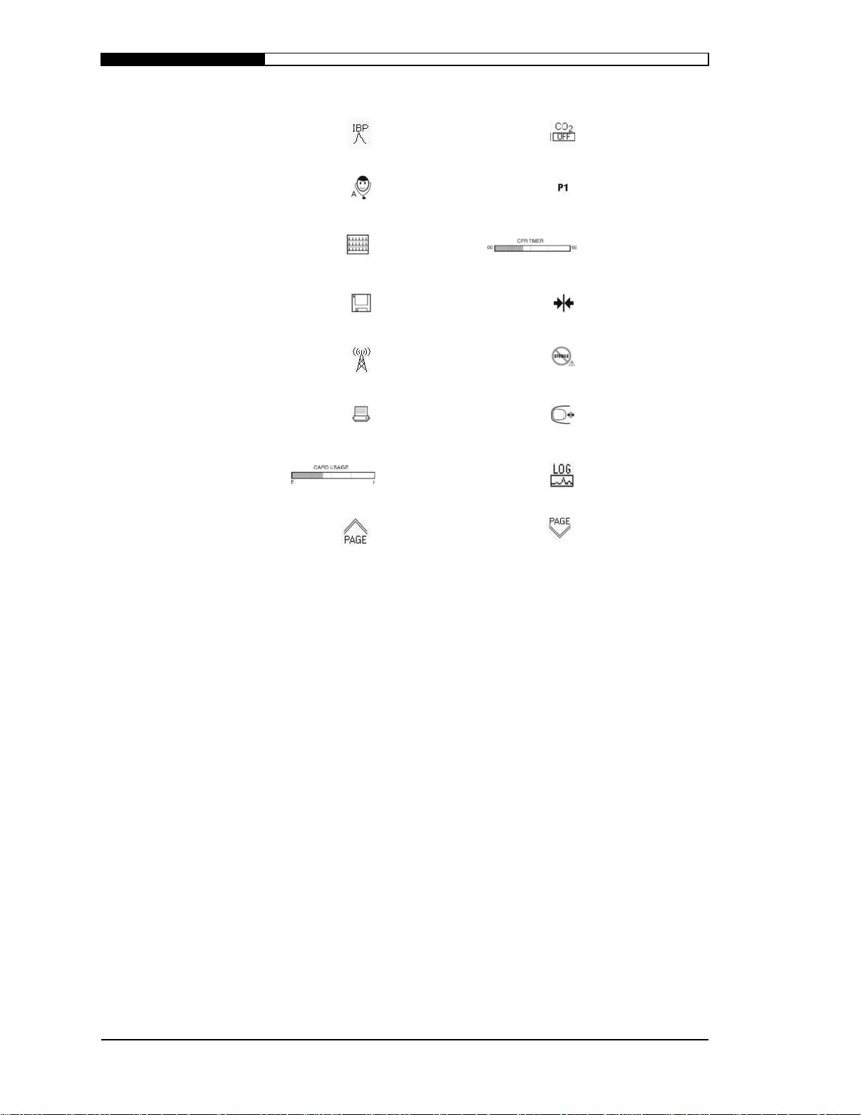
S
AFETY INFORMATION
Invasive blood
pressure Carbon dioxide off
Resets to patient
Analyze 12-lead
Card Review/
12-lead next page SAED CPR timer
001 in card review
12-lead save
function
Fax/modem Do not sterilize
Card review/
12-lead printer
Card review card
usage and location
12-lead analysis
page up
Latching
connection
Press here to
unlatch
Quick access Log
button
12-Lead analysis
page down
1.4
WELCH ALLYN PORTABLE INTENSIVE CARE SYSTEM
Page 15

S
The Welch Allyn PIC is intended for use by trained, authorized
medical personnel who are familiar with basic monitoring, vital signs
assessment and emergency cardiac care. The PIC is also intended for
use by physicians at the scene of an emergency or in a hospital
emergency room.
Federal (USA) law restricts this device to sale by or on the order of a
physician.
Any authorized person using the Welch Allyn PIC should be
completely knowledgeable of the information in the User Instruction
Manual.
The defibrillator function of the PIC is used to treat: ventricular
fibrillation and pulseless ventricular tachycardia. The biphasic
waveform employed by the PIC has not been clinically tested on
pediatric patients. The device has not been evaluated for
cardioversion of atrial fibrillation or direct (internal) cardiac
defibrillation. The semi-automatic mode should not be used on
pediatric patients less than 8 years old.
Use only authorized Welch Allyn accessories listed in the
Introduction chapter of this manual. Use of unauthorized accessories
may cause the device to operate improperly and provide false
measurements.
Do Not attempt to sterilize any accessory or equipment.
Proper care and maintenance of the Welch Allyn batteries is
important to insure continuous operation during patient care. If the
batteries are not maintained properly, loss of power during patient
care could result, affecting patient care. Always have a fully charged
battery pack available as a back-up.
g
If this device has been dropped or damaged in any way, refer the
device to qualified service personnel for verification of performance
and/or servicing.
T o achieve the specified level of pr otection against spilled or splashed
liquids, thoroughly dry all exposed surfaces of this device prior to
operation or connections to mains power.
AFETY INFORMATION
*HQHUDO3UHFDXWLRQV
Accessories
Sterilization
Battery Care
Dropped or
Dama
ed
Ingress of Liquids
WELCH ALLYN PORTABLE INTENSIVE CARE SYSTEM
1.5
Page 16

Electrical Shock
Hazard
: Do not use the PIC if it has been immersed in a liquid or if
liquid has spilled on it. Do not clean the PIC with alcohol, ketone, or
any flammable agent. Do not autoclave the PIC. Conductive parts of
electrodes and connectors, for applied parts, should not contact other
conductive parts including earth.
Hazard
: This device does not contain any user-serviceable parts. Do
not remove instrument covers or attempt to repair the Welch Allyn
PIC System. Refer servicing to qualified personnel.
When obtaining a new supply of disposable electrodes for
monitoring, defibrillation or pacing, verify that they will properly
connect to the existing Welch Allyn cables prior to putting in service.
Do not use if gel is dry.
Hazard
: The PIC can deliver 360 Joules of electrical energy. If this
electrical energy is not discharged properly, as described in the User
Instruction Manual, the electrical energy could cause personal injury
or death to the operator or bystander.
Always verify expiration dates on dated items such as disposable
defibrillation or pacing pads, monitoring electrodes and battery packs.
If the expiration date has passed, replace the disposable items
immediately.
Biomedical equipment and accessories, such as ECG electrodes,
cables, and oximeter probes contain ferromagnetic materials.
Ferromagnetic equipment must not be used in the presence of high
magnetic fields created by magnetic resonance imaging (MRI)
equipment.
The large magnetic fields generated by an MRI device can attract
ferromagnetic equipment with an extremely violent force, which
could cause serious personal injury or death to persons between the
equipment and the MRI device.
Observe all PRECAUTION and WARNING labels on the Welch
Allyn PIC System and Quick Charger/Conditioner.
g
Hazard
: Care should be exercised when operating the Welch Allyn
PIC and Welch Allyn Quick Charger/Conditioner in the presence of
oxygen sources (such as near bag-valve-mask devices or ventilators),
flammable gases or anesthetics. These environments can produce fire
or explosion hazards.
Electrical Shock
(Internal)
Electrodes
(Disposable)
Energy Discharge
S
AFETY INFORMATION
Expiration Date
Ferromagnetic
Equipment
Labels
Operating Near
en
Oxy
1.6
WELCH ALLYN PORTABLE INTENSIVE CARE SYSTEM
Page 17

S
Place the PIC System, accessories and cables in a position where they
cannot harm the patient should they fall. Keep all cables and hoses
away from patient’s neck.
The Welch Allyn PIC System may not meet performance
specifications if stored, transported, or used outside the specified
storage or operating environmental range limits.
g
To prevent incorrect trending data from being printed, clear the
Treatment Summary Log from the Recorder-Log menu prior to use
on a new patient.
AFETY INFORMATION
Patient Physical
Harm
Performance
Treatment Summary
Lo
WELCH ALLYN PORTABLE INTENSIVE CARE SYSTEM
1.7
Page 18

0RQLWRULQJ3UHFDXWLRQV
•
WARNING: PACEMAKER PA TIENTS
. The W elch Allyn
PIC includes a pacemaker rejection circuit. The following
warning is in accordance with the disclosure requirement of
AAMI Standard EC13-3.1.2.1 (8): The rate meter may
continue to count the pacemaker rate during some
occurrences of cardiac arrest or some arrhythmias. Do not
rely upon the heart rate meter alarms to assess the patient’s
condition. Keep pacemaker patients under close surveillance.
Pacemaker pulses of the type specified in AAMI EC13-1992,
section 3.1.4, are detected at amplitudes greater than ± 20mV
and rejected by the heart rate display. However, pacemaker
pulses that are superimposed on the ECG at very low
amplitudes may be counted by the heart rate display. NOTE:
This warning is an AAMI requirement that applies to all ECG
monitors, regardless of make or model.
•
Use only Welch Allyn patient cables. Other cables can
produce excessive artifact, causing an inability to interpret
the ECG.
•
Use only ECG electrodes that meet the AAMI standard for
electrode performance (AAMI EC-12). Use of electrodes not
meeting this AAMI standard could cause the ECG trace
recovery after defibrillation to be significantly delayed.
•
The type of surface electrode and the technique used in
applying the electrodes are major factors in determining the
quality of the signal obtained. Use high-quality, silver-silver
chloride electrodes. These electrodes are designed to provide
excellent baseline stability, provide rapid recovery from
defibrillation, and minimize artifacts from patient movement.
•
When attempting to interpret subtle ECG changes (ST
segments, etc.), use only the diagnostic frequency response
mode. Other frequency response settings may cause
misinterpretation of the patient’s ECG. See Frequency
Response in chapter 13 for further details.
•
Excessive artifact can result due to improper skin preparation
of the electrode sites. Follow skin preparation instructions in
chapter 4.
•
Do not operate the PIC System in conjunction with
electrocautery or diathermy equipment. Such equipment, as
well as equipment that emits strong radio frequency signals,
can cause electrical interference and distort the ECG signal
displayed by the monitor, thereby preventing accurate rhythm
analysis.
S
AFETY INFORMATION
1.8
WELCH ALLYN PORTABLE INTENSIVE CARE SYSTEM
Page 19

S
•
Do not operate the PIC in close proximity to any other
monitor with respiration measurements. The two devices
could affect the respiration accuracy.
•
Any external connection to the 1V or MOD outputs must
comply with clause 19 of IEC 601-1 for leakage current and
must not exceed 450 mA.
•
Shock Hazard: Use of accessories, other than those specified
in the operating instructions, may adversely affect patient
leakage currents.
•
Certain line-isolation monitors may cause interference on the
ECG display and may inhibit heart rate alarms.
•
The Welch Allyn PIC can deliver 360 joules of electrical
energy. If this electrical energy is not discharged properly, as
described in the User Instruction Manual, the electrical
energy could cause personal injury or death to the operator or
bystander.
•
The operator and all other people must stand clear of the
patient, the bed and all conductive surfaces (that are in
contact with the patient) during defibrillation. The electrical
energy delivered to the patient could also be delivered to any
other person who is in contact with the patient or the
conductive surface.
•
Do not use the defibrillator in the presence of oxygen sources
(such as near bag-valve-mask devices or ventilators),
flammable gases or anesthetics. These environments can
produce fire or explosion hazards.
•
After a synchronized cardioversion, the SYNC mode may be
cleared after each shock or disarm. The user may have to
reselect (press) the SYNC button after each synchronized
cardioversion shock performed on a patient. The PIC can be
configured in the Supervisor-Defibrillation Set-up menu to
remain in the SYNC mode after each synchronized
cardioversion.
•
Synchronized cardioversion can be performed in the paddle
monitoring mode. However, it is possible that artifact can be
produced by the moving paddles, which could cause the
defibrillator to trigger on the artifact. It is recommended that
monitoring in leads I, II or III be used during synchronized
cardioversion. Paddle monitoring should not be used for
elective cardioversions procedures.
AFETY INFORMATION
'HILEULOODWRU3UHFDXWLRQV
WELCH ALLYN PORTABLE INTENSIVE CARE SYSTEM
1.9
Page 20

S
•
To avoid stress to the defibrillator or the tester, never attempt
to repeatedly charge and discharge the defibrillator in rapid
succession. If a need for repetitive testing arises, allow a
waiting period of at least 2 minutes for every third discharge.
•
Monitoring ECG through the paddles may result in inaccurate
heart rate display due to artifact.
•
In the SYNC mode, the defibrillator will not discharge
without a command signal (R-wave detection) from the ECG
monitor indicated by a SYNC marker on the trace, flashing
SYNC indicator, and an audible beep if the R-wave beeper is
enabled.
•
Do not use the defibrillator if excessive condensation is
visible on the device. Wipe only the outside with a damp
cloth.
•
Use only W elch Allyn-approv ed disposable defibrillation and
pacing pads and cables.
•
Defibrillator paddles should be kept clean and dry when not
in use. When preparing electrodes and during defibrillation
procedures, extreme care should be exercised to prevent gel
or any conductive material from forming a contact between
the operator and the paddles. Do not allow gel or any other
conductive material to form an electrical bridge between the
defibrillator electrodes or to the monitoring electrodes.
Electrical arcing and/or patient burns could occur during
defibrillation. Arcing and patient burns could prevent
sufficient energy delivery to the patient.
•
WARNING
: If conductive gel forms a continuous path
between the defibrillator electrodes, delivered energy may be
dramatically reduced to zero. In this case, reposition the
electrodes to eliminate the shunting path before attempting
additional shocks.
•
Improper defibrillation technique can cause skin burns. To
limit possible skin burns, use only Welch Allyn defibrillation
gel on paddles, insure the gel covers the entire paddle surface
and press firmly against patient’s chest.
•
Disposable defibrillation electrodes must be used in
accordance with the manufacturer’s instructions. Do not use
expired, dry electrodes or reuse disposable electrodes, as
improper patient contact may result in patient burns and
inability of the device to function properly.
AFETY INFORMATION
1.10
WELCH ALLYN PORTABLE INTENSIVE CARE SYSTEM
Page 21

S
•
The device contains an automatic disarm of the capacitor
bank. If the operator has not delivered the charge to a patient
or test load, an internal timer will disarm the capacitor bank 1
minute in manual mode and 30 seconds in SAED Basic or
SAED Basic+ mode after the ready charge signal. The ready
charge signal is indicated by a continuous audible tone and
the energy availability graph displayed on the monitor.
•
If a new energy level is selected after the charge button is
pushed and while the defibrillator is charging, defibrillator
will automatically charge to the new energy selection. The
CHARGE button need not be pressed again to select the new
energy level.
•
Disconnect from the patient any medical electronic device
that is not labeled “defibrillation protected.”
•
Before charging the defibrillator, verify that the energy
selected on the display is the desired output.
•
Some erythema of the skin and/or minor burns may occur
during defibrillation. Use proper defibrillation techniques, as
outlined in the User Instruction Manual, to minimize
erythema/burns.
•
Defibrillation will take priority over external pacing. Should
the defibrillator be charged during the administration of
external pacing, the pacer will automatically be turned off
and the defibrillator will charge to the selected energy.
•
Transcutaneous pacing should not be used to treat V FIB
(ventricular fibrillation). In cases of V FIB, immediate
defibrillation is advised.
•
Transcutaneous pacing may cause discomfort ranging from
mild to severe, depending on the patient’s tolerance level,
muscle contractions and electrode placement. In certain
cases, discomfort may be decreased by slightly relocating the
pacing pads.
•
It is important to monitor the patient closely to verify that
both mechanical and electrical capture are occurring.
Electrical capture can be verified by observing the presence
of a large ectopic beat after the pacing pulse is delivered. The
size and morphology of the beat are dependent on the patient.
In some instances the beat may appear as a relatively normal
looking QRS pulse. Mechanical capture can be verified by
checking for signs of increased blood flow i.e., reddening of
AFETY INFORMATION
([WHUQDO3DFLQJ3UHFDXWLRQV
WELCH ALLYN PORTABLE INTENSIVE CARE SYSTEM
1.11
Page 22

S
the skin, palpable pulses, increased blood pressure, etc. (See
chapter 8). Continuously observe the patient during pacing
administration, to insure capture retention. Do not leave the
patient unattended when administering external pacing
therapy.
•
Some erythema of the skin and/or minor burns may occur
under the pacing electrodes in some patients. For prolonged
periods of pacing (>4 hours), periodically inspecting the skin
beneath the electrodes (when patient’s condition allows) is
recommended. Discontinue external pacing if the skin is
affected and if another form of pacing is available.
•
Disposable defibrillation/pacing electrodes must be used in
accordance with the manufacturer’s instructions. Do not use
expired, dry electrodes or reuse disposable electrodes, as
improper patient contact may result in patient burns and
inability of the device to function properly.
•
The pacing rate determination can be adversely affected by
artifact. If the patient’s pulse and the heart rate display are
significantly different, external pacing pulses may not be
delivered when required.
•
WARNING: PACEMAKER PA TIENTS
. The W elch Allyn
PIC includes a pacemaker rejection circuit. The following
warning is in accordance with the disclosure requirement of
AAMI Standard EC-13-3.1.2.1 (8): The rate meter may
continue to count the pacemaker rate during some
occurrences of cardiac arrest or some arrhythmias. Do not
rely upon the heart rate meter alarms to assess the patient’s
condition. Keep pacemaker patients under close surveillance.
Note: This warning is an AAMI requirement that applies to
all ECG monitors, regardless of make or model.
•
Artifact and ECG noise can make R-wave detection
unreliable, affecting the HR meter and the demand mode
pacing rate. Always observe the patient closely during pacing
operations. Consider using asynchronous pacing mode if a
reliable ECG trace is unobtainable.
AFETY INFORMATION
1.12
WELCH ALLYN PORTABLE INTENSIVE CARE SYSTEM
Page 23

S
•
Keep the Welch Allyn finger probe clean and dry.
•
SpO2 measurements may be affected by certain patient
conditions: severe right heart failure, tricuspid regurgitation
or obstructed venous return.
•
SpO2 measurements may be affected when using
intravascular dyes, in extreme vasoconstriction or
hypovolemia or under conditions where there is no pulsating
arterial vascular bed.
•
SpO2 measurements may be affected in the presence of
strong EMI fields, electrosurgical devices, IR lamps, bright
lights, improperly applied sensors; the use of non-Welch
Allyn sensors, or damaged sensors; in patients with smoke
inhalation, or carbon monoxide poisoning, or with patient
movement.
•
Tissue damage can result if sensors are applied incorrectly, or
left in the same location for an extended period of time. Move
sensor every 4 hours to reduce possibility of tissue damage.
•
Do not use any oximetry sensors during MRI scanning. MRI
procedures can cause conducted current to flow through the
sensors, causing patient burns.
•
Do not apply SpO
2
sensor to the same limb that has an NIBP
cuff. The SpO
2
alarm may sound when the arterial circulation
is cut off during NIBP measurements, and may affect SpO
2
measurements.
•
WARNING
: In some instances, such as obstructed airway,
the patient's breathing attempts may not produce any air
exchange. These breathing attempts can still produce chest
size changes, creating impedance changes, which can be
detected by the respiration detector. It is best to use the pulse
oximeter whenever monitoring the respirations, to accurately
depict the patient's respiratory condition.
AFETY INFORMATION
3XOVH2[LPHWHU3UHFDXWLRQV
WELCH ALLYN PORTABLE INTENSIVE CARE SYSTEM
1.13
Page 24

S
•
Only a physician can interpret pressure measurements.
•
Blood pressure measurement results may be affected by the
position of the patient, his or her physiological condition and
other factors.
•
Substitution of a component different from that supplied by
Welch Allyn (e.g., cuff, hoses, etc.) may result in
measurement error. Use only Welch Allyn cuffs and hoses.
•
Do not use a blood pressure cuff on the limb being used for
IV infusion or for SpO
2
monitoring.
•
Accurate pressure readings may not be achieved on a person
experiencing arrhythmias, shaking, convulsions or seizures.
Medication may also affect pressure readings. The correct-
size cuff is essential for accurate blood pressure readings.
•
Blood pressure hoses must be free of obstructions and
crimps.
•
If the patient’s cuff is not at heart level, an error in
measurement may result.
•
When monitoring blood pressure at frequent intervals,
observe the cuffed extremity of the patient for signs of
impeded blood flow.
•
WARNING
: THIS DEVICE IS NOT APPROVED FOR
USE ON NEO-NATAL PATIENTS.
•
Do not monitor one patient’s NIBP while monitoring another
patient’s ECG.
•
Blood pressure measurement may be inaccurate if taken
while accelerating or decelerating in a moving vehicle.
•
If an NIBP measurement result is questionable or “motion”
indication is displayed, repeat the measurement. If the
repeated measurement result is still questionable, use another
blood pressure measurement method.
•
Do not use the NIBP on cardiopulmonary bypass patients.
1RQ,QYDVLYH%ORRG3UHVVXUH3UHFDXWLRQV
AFETY INFORMATION
1.14
WELCH ALLYN PORTABLE INTENSIVE CARE SYSTEM
Page 25

S
•
Use only Welch Allyn SmartPak or Welch Allyn SuperPac
batteries in the W elch Allyn PIC. Use of any other battery can
damage the Welch Allyn PIC and not provide sufficient
power, inhibiting patient care.
•
If the Low Battery indication occurs at any time during
operation, immediately replace the battery pack with a
battery pack known to be fully charged. Always have a fully
charged battery pack available as a back-up.
•
Due to the critical nature of all batteries, replacement of the
Welch Allyn batteries is recommended at 24-month intervals.
•
Proper care and maintenance of the Welch Allyn batteries is
important to ensure continuous operation during patient care.
If the batteries are not maintained properly, loss of power
during patient care could result, affecting patient care.
•
The battery packs contain materials such as stainless steel,
cadmium and nickel, which can be recycled. They must be
disposed of properly. Consult local authorities for proper
disposal.
AFETY INFORMATION
%DWWHU\3UHFDXWLRQV
WELCH ALLYN PORTABLE INTENSIVE CARE SYSTEM
1.15
Page 26

&KDUJHU3UHFDXWLRQV
•
Charge only Welch Allyn SmartPak or SuperPac batteries in
the Welch Allyn Quick Charger/Conditioner. Charging any
other battery can cause damage to the Quick Charger.
•
Do not insert objects into or block the charger’s ventilation
ports.
•
When testing the defibrillator on the charger’s defibrillation
output tester, ensure that the paddle surface is positioned
properly in the paddle test well. Do not use gel during this
test, and ensure that the paddle surface is not contacting the
metal charger frame. When discharging the paddles into the
tester, press the paddles firmly into the test well to prevent
pitting the paddle surfaces.
•
Only test Welch Allyn defibrillators on the charger’s
defibrillation output tester. Testing other brands of
defibrillators will damage the charger’s defibrillation output
tester.
•
Do not take charger or paddle holder apart or attempt to
repair it yourself.
•
The Welch Allyn charger should not be used in the presence
of flammable anesthetics or materials.
•
If the charger has been dropped or shows visible signs of
abuse, refer device to qualified service personnel for
verification of proper operation.
•
Do not immerse the charger or expose it to water or other
liquids.
•
Wipe only the outside with a damp cloth.
•
Tighten clamp onto power cord to prevent its accidental
removal.
•
Unplug the charger prior to changing the fuse.
•
Use only the W elch Allyn Quick Char ger to power the Welch
Allyn PIC System from an auxiliary power source.
•
Do not use the Welch Allyn Quick Charger to power any
non-Welch Allyn devices.
•
A depleted battery could increase defibrillator charge times.
•
It is recommended that a fully charged battery be inserted in
the PIC System even when operating on auxiliary power.
S
AFETY INFORMATION
NOTE:The PIC System will operate from an auxiliary power source
without a battery inserted or if the inserted battery is depleted.
However, under these circumstances, defibrillator charge time
will be slightly longer (10 seconds typical, 15 sec. maximum).
1.16
WELCH ALLYN PORTABLE INTENSIVE CARE SYSTEM
Page 27

S
•
WARNING: Cardiac Pacemakers
. The presence of an
internal cardiac pacemaker may adversely affect analysis
results. If it is known, or suspected, that the patient is fitted
with a cardiac pacemaker, follow your own locally-
established procedure for dealing with defibrillation of such
patients.
•
The PIC, in SAED mode, should only be applied to victims
of cardiac arrest who exhibit unconsciousness, absence of
breathing, and absence of pulse.
•
Excessive motion may affect analysis results. ECG analysis
should not be performed when the patient is being moved.
Stop all patient movement and do not touch patient when the
ECG analysis is in process. Take precautions to eliminate
sources of motion or artifact before monitoring in SAED
mode.
•
To insure compatibility and electrical safety, accessory
pressure sensors should comply with ANSI/AAMI BP-22 and
IEC 601-2-34 for IBP or ANSI/AAMI NS28 for ICP
•
Follow instructions supplied with any accessory pressure
sensor regarding calibration and removal of trapped air.
•
Avoid touching metal parts of any transducer while it is in
contact with the patient.
•
Do not reuse any components that are labeled for single use
only.
•
Transducers should be rated to withstand an accidental drop
of at least a meter onto a hard surface.
•
Transducers that are subject to immersion in liquids should
be rated as watertight.
AFETY INFORMATION
6$('3UHFDXWLRQV
,%33UHFDXWLRQV
WELCH ALLYN PORTABLE INTENSIVE CARE SYSTEM
1.17
Page 28

&23UHFDXWLRQV
•
Do not use CO
2
sensor during MRI scanning. MRI
procedures can permanently damage the CO
2
sensor.
•
CO2/ETCO
2
measurements may be affected by the presence
of interfering gases or vapors. Do not use on a patient being
administered oxygen or nitrous oxide.
•
Use only Welch Allyn CO
2
sensors and adapters.
•
Do not reuse airway adapters that are labeled for single
patient use.
•
Prior to using airway adapter check for lodged obstructions.
After attaching, check the sensor for proper placement of the
sensor.
•
If using the CO
2
Monitor for extended critical care, replace
the airway adapter every 24 hours or when it becomes
occluded.
•
Do not use with patients with a low tidal volume, such as
patients younger than 3 years of age or weighing less than
22 pounds, or patients with a respiration rate greater than or
equal to 60 breaths per minute.
•
Accuracy is based upon 1 atmospheric pressure and no
residual CO
2
gas left in the sensor from previous expiration.
The CO
2
trace will be displayed as if that is the case.
S
AFETY INFORMATION
1.18
WELCH ALLYN PORTABLE INTENSIVE CARE SYSTEM
Page 29
HAPTER
g
g
y
C
This chapter introduces the Welch Allyn Portable Intensive Care (PIC) System beginning
2: I
NTRODUCTION
with a brief listin
numbers and checklists of available options and accessories. The chapter concludes with
procedures and considerations for unpackin
Chapter Overview:
of features and benefits. This is followed by an explanation of the part
, installing, and operating the system.
• Product Overview. . . . . . . . . . . . . . . . . . . . . . . . . . . . . . . . . 2.2
• Indications for Use . . . . . . . . . . . . . . . . . . . . . . . . . . . . . . . .2.4
• Part Numbers . . . . . . . . . . . . . . . . . . . . . . . . . . . . . . . . . . . .2.6
• Options and Accessories . . . . . . . . . . . . . . . . . . . . . . . . . . .2.7
• Initial Installation Evaluation. . . . . . . . . . . . . . . . . . . . . . . . .2.9
• Summar
of Operations . . . . . . . . . . . . . . . . . . . . . . . . . . . . 2.11
Welch Allyn Portable Intensive Care (PIC) System
W
ELCH ALLYN PORTABLE INTENSIVE CARE SYSTEM
2.1
Page 30

3URGXFW2YHUYLHZ
The Welch Allyn Portable Intensive Care (PIC) System is an
extremely flexible device that incorporates an ECG monitor,
defibrillation (manual and semi-automated), external pacer, pulse
oximeter, non-invasive blood pressure, and respiration monitoring.
The PIC System’s small, lightweight package makes it ideal for
transport situations, and it has been designed for use in and out of the
hospital.
•
Flexible design
•
Small, lightweight
•
Pulse oximetry and NIBP options available
•
Large (6.5") bright, easy-to-read display
•
Three simultaneous traces
•
Treatment Summary documentation
•
Voice Memo
TM
storage and retrieval
•
Card review
•
User-configurable options
•
Simple menus
•
Hands-free defibrillation
•
Mains (AC) and battery power capability
•
Upgradable for future expansion
The PIC has been designed to allow additional monitoring options to
be installed anytime in the future. System can grow with your needs.
Weighing only 10 pounds, and not much larger than a cardiac
monitor, this full-function intensive care tool is ideal for
transport/portable applications.
g
Using surface mount component technology, miniaturization allows
pacing, pulse oximetry, NIBP, respiration, and temperature to be
added in the same small package as the ECG monitor and
defibrillator.
y
A large, bright display allows viewing the critical parameters from
across the room and from any angle.
Key Features
I
NTRODUCTION
Flexible Design
Small, Lightweight
Multiparameter
Monitorin
Large, Bright Displa
2.2
WELCH ALLYN PORTABLE INTENSIVE CARE SYSTEM
Page 31

I
ECG, plethysmograph, and/or respirations waveforms can be
displayed at one time, thus providing more information with which to
assess the patient.
y
Welch Allyn-exclusive documentation systems will record the time
and ECG sample of key ACLS procedures and drugs for future
retrieval.
A quick and convenient means of documenting important
information. When you are busy treating the patient and you need to
document an important piece of information (initial vital signs,
medications, allergies, etc.), just press the Voice Memo
TM
button and
the audio information will be digitally recorded in the PIC . The
recorded information can be played back directly from the PIC .
The PIC System's Card Review option is a unique feature used to
assist the operator in reviewing patient information that has been
recorded to a data card including ECG, event, and speech data. The
Card Review feature groups ECG, event, and speech data into
individual patient records. This information can be viewed and
printed on the PIC System using the Card Review menu or viewed
and printed on a PC using Welch Allyn provided SmartView
software.
Allows flexibility by configuring the PIC to meet the needs of your
department, shift or patient.
Includes Supervisor menus to eliminate confusing menus during
emergency use.
Compatible with disposable multifunction monitoring/defibrillation/
pacing pads, allowing fast, convenient and safe defibrillation and
pacing.
y
y
Can operate from NiCad or NiMH quick-change battery packs, AC
mains or 12V operation.
The design will allow for future expansion of enhanced 12-lead
monitoring, fax modem transmissions, semi-automatic (shock
advisory) defibrillation capability, invasive pressures, and CO
2
monitoring.
NTRODUCTION
Three Simultaneous
Traces
Treatment Summar
Voice Mem o
Card Review
User-Configurable
Options
Simple Menu
Hands-FreeTM
Defibrillation Pads
Mains (AC) and
Batter
capabilit
Upgradable Design
power
WELCH ALLYN PORTABLE INTENSIVE CARE SYSTEM
2.3
Page 32

,QGLFDWLRQVIRU8VH
Without the SAED option, the PIC is intended primarily for use by
emergency responders, trained in advanced life support, cardiac care
techniques, interpretation of ECG waveforms, and the use of the PIC.
With the SAED option, the PIC may be used by emergency
responders, trained in basic life support, cardiac care techniques, and
the use of the PIC. The usage may be in an ambulance or at the scene
of an emergency. The PIC is also intended for use by (or on the order
of) physicians at the scene of an emergency or in a hospital
emergency room, intensive care unit, cardiac care unit, or other
similar areas of a hospital. It is also intended to be used during the
transport of patients between any of the locations mentioned above.
The patient population will consist of adults and children (described
below), and will consist of patients both with and without heart
dysfunction. The PIC will be used primarily on patients expe riencing
symptoms of cardiac arrest or in a post trauma situation. It may also
be used whenever it is required to monitor any of those functions that
are included (as options) in the device. Indications for each of the
specific functions are discussed below.
The defibrillator function of the PIC is used to treat: ventricular
fibrillation and pulseless ventricular tachycardia. The biphasic
waveform employed by the PIC has not been clinically tested on
pediatric patients. The device has not been evaluated for
cardioversion of atrial fibrillation or direct (internal) cardiac
defibrillation. The semi-automatic mode should not be used on
pediatric patients less than 8 years old.
The ECG monitor function of the PIC is used to monitor and/or
record ECG waveform and heart rate, and to alarm when heart rate is
above or below limits set by the operator. The PIC also provides
output signals for the purpose of sending ECG waveforms to a remote
monitor via direct connection, telephone, or radio transmission.
Patients may range from neo-natal to adult.
The external transcutaneous pacing function of the PIC is used for the
emergency treatment of hemodynamically compromising
bradycardia, bradycardia with escape rhythms that are unresponsive
to pharmacologic therapy, refractory tachycardia (supraventricular or
ventricular), and bradyasystolic cardiac arrest. Patients may range
from pediatric to adult.
I
NTRODUCTION
Defibrillator
Function
ECG Monitor
Function
External
Transcutaneous
Pacemaker
Function
2.4
WELCH ALLYN PORTABLE INTENSIVE CARE SYSTEM
Page 33

I
The non-invasive blood pressure function of the PIC is used to make
non-invasive measurements of arterial pressure and heart rate, and to
alarm if either parameter is outside of the limits set by the user.
Measurements are made using an inflatable cuff on the patient's arm
or (occasionally) leg. Patients may range from pediatric to adult.
The temperature monitor function of the PIC is used to make
continuous measurements of rectal, esophageal, or surface
temperature, and to alarm if the temperature is outside of the limits set
by the user. It is used on patients ranging from neo-natal to adult.
The pulse oximeter function of the PIC is used to monitor pulse rate
and oxygen saturation of arteriolar hemoglobin, and to alarm if either
parameter is outside of the limits set by the user . It is used on patients
ranging from neo-natal to adult. Measurements are made non-
invasively at remote sites such as a finger, toe, ear lobe, bridge of
nose, etc. It is used on patients ranging from neo-natal to adult.
The respiration rate monitor function of the PIC is used to
continuously monitor respiration rate and to alarm if the rate falls
outside of the range set by the operator. The patients range from neo-
natal to adult. Because the measurement method actually measures
respiratory effort, apnea episodes with continued respiratory effort
(such as obstructive apnea) may not be detected. It
is not intended
to
be used as an apnea monitor. It is used on patients ranging from neo-
natal to adult.
The respiration rate monitor function of the PIC is used to measure
the concentration of carbon dioxide in a gas mixture to aid in
determining the patient's ventilatory status. This device is intended as
an indicator of patient carbon dioxide concentration during expiration
and is not intended as the sole basis for medical diagnosis.
This CO
2
monitor is intended for use with patients 3 years of age and
older. This device is not recommended for patients with low tidal
volume such as patients younger than 3 years of age or weighing less
than 22 pounds, or patients with a respiration rate greater than or
equal to 60 breaths per minute.
NTRODUCTION
Non-Invasive
Blood Pressure
Function
Temperature
Monitor Function
Pulse Oximeter
Function
Respiration Rate
Monitor Function
CO2 Monitor
Function
WELCH ALLYN PORTABLE INTENSIVE CARE SYSTEM
2.5
Page 34

3DUW1XPEHUV
g
Welch Allyn us es a part numbering system that allows both the user
and service technician to understand what type of unit and installed
options are in each PIC System.
PIC System Part
Numberin
I
NTRODUCTION
PIC50
All Basic base units include Color Display, Nellcor Oximeter (971074) and Voice
Memo (971005)
971081 PIC50, 5-Lead
971083 PIC50, 12-Lead
All Deluxe base units include Color Display, Nellcor Oximeter (971074), Voice
Memo (971005), and Blood Pressure (971001)
971082 PIC50, 5-Lead
971084 PIC50, 12-Lead
All regular base units include Color Display and no options:
971085 PIC50, 5-Lead
971086 PIC50, 12-Lead
PIC40
All units have Color Display
973092: PIC40, Basic
973093: PIC40 with Blood Pressure (971001) option
973094: PIC40 with Blood Pressure (971001) and Pacing (971091) options
973095: PIC40 with Pacing (971091) option
Destination Codes:
Destination code denotes required language and power options
E = English - US
S = Spanish - Europe
G = German
F = French
I = Italian
P = Portuguese
U = English - UK
A = Australia
M = Mexico - Spanish Central and South America
T = South Africa
W = English - World
2.6
WELCH ALLYN PORTABLE INTENSIVE CARE SYSTEM
Page 35

I
The following options and accessories are available for the PIC. For
future reference, check off which options and accessories you
currently have from the information provided on the packing list.
Should you want to upgrade your system or purchase additional
accessories, please contact Welch Allyn at (800) 462-0777.
NTRODUCTION
2SWLRQVDQG$FFHVVRULHV
Options Available
Accessories
971074 Pulse oximeter
Y
971001 NIBP and Temperature
Y
971005
Y
971008 SAED
Y
971019 Fax
Y
971106 Adult paddles
Y
971108 Adult deluxe paddles
Y
001537 Pediatric adapters (set)
Y
971107 Hands-free defibrillator
Y
900322 Hands-free defibrillator
Y
001636 Welch Allyn Smart Pak
Y
001638 Welch Allyn Smart Pak
Y
001647 Welch Allyn SuperPac
Y
900214 Carrying case
Y
900223 Carrying case for unit with
Y
971104 Welch Allyn Quick Charger
Y
001739 Recorder paper
Y
001966 SPO2 adapter cable
Y
002111 Finger probe, reusable,
Y
002052
Y
Voice Memo
adapter
tester
battery
Plus battery
integral charger
adult
KLEAN TRACE
ductive spray
TM
TM
con-
971024 Data Card Review/Record
Y
971016 CO
Y
971017 IBP
Y
971018 12-Lead Analysis
Y
001790 3-lead patient cable
Y
001794 3-lead patient cable w/intnl
Y
001795 5-lead patient cable
Y
001796 5-lead patient cable w/intnl
Y
001720 Bitrode limb electrodes
Y
001834 12 Lead breakaway
Y
001837 12 Lead breakaway
Y
001798 3 Lead patient cable for
Y
001948 3 Lead patient cable for
Y
980139 3 Lead Simulator
Y
980140 12 Lead Simulator
Y
001938 Fax output cable
Y
001726 ECG electrodes
Y
002051 Defibrillator gel
Y
001853 Multipurpose electrodes
Y
2
color code
color code
patient cable
patient cable IEC
12 Lead
12 Lead, IEC
(adult)
WELCH ALLYN PORTABLE INTENSIVE CARE SYSTEM
2.7
Page 36

I
NTRODUCTION
001942 NIBP Adult disposable cuff
Y
001943 NIBP Thigh disposable
Y
001944 NIBP hose for use with
Y
001945 NIBP Pediatric disposable
Y
001946 NIBP hose for use with
Y
001911 NIBP adult thigh cuff
Y
001915 NIBP adult large arm cuff
Y
001912 NIBP adult arm cuff
Y
001913 NIBP child cuff
Y
001914 NIBP infant cuff
Y
001922 NIBP cuff hose, 6ft.
Y
001923 NIBP cuff hose, 10ft
Y
001957 IBP Adapter Cable
Y
001927 Disposable skin tempera-
Y
971126 Hands free adapter,
Y
981120 Defib cable tester
Y
981122 2-bay charger, SuperPac
Y
cuff
disposable cuffs - 6’
cuff
disposable cuffs - 10’
ture sensor
straight
001828 Multipurpose electrodes
Y
001930 Adult disposable tympanic
Y
001931 Pediatric disposable tym-
Y
001932 Reusable 10 ft extension
Y
001933 Calibration check plug
Y
001950 CO2 airway adapter -
Y
001951 CO2 airway adapter -
Y
001954 CO2 adapter
Y
001934 CO2 sensor
Y
001910 SmartView Software and
Y
980136 CardioLog memory card –
Y
980137 CardioLog memory card –
Y
980138 CardioLog memory card –
Y
971029 Internal Charger
Y
001941 Quick combo pad adapter
Y
002129 Welch Allyn to Zoll pad
Y
981124 1-bay charger, SuperPac
Y
(child)
temp sensor
panic temp sensor
cable for all disposable
temp sensors
Qty 5
Qty 50
Manual
4mb
8mb
16mb
adapter cable
2.8
WELCH ALLYN PORTABLE INTENSIVE CARE SYSTEM
Page 37

I
T o determine the initial installatio n condition of the Welch Allyn PIC
System after shipment, follow the simple steps below.
Visually inspect the carton and the equipment for any signs of
damage or mishandling (carton perforations, cuts or dents, bent or
collapsed corners, or broken carton seal). If damaged, contact
Welch Allyn immediately.
1.
Open and carefully unpack each carton.
2.
Examine the instrument and accessories for signs of
damage.
3.
Check the packing list to determine that all accessories have
been received.
Save all packing materials, invoicing and any other paperwork.
If any problem is encountered in unpacking the PIC System, contact
the Welch Allyn Service Department at (847) 520-0300 for further
instructions.
In order to ensure that the device is running properly after shipping,
follow the instructions below.
1.
Connect defibrillator multipurpose hands-free adapter (see
Fig. 1).
2.
Charge all batteries prior to first use.
3.
Insert a fully charged Welch Allyn Smart Pak battery into
the battery slot, or use the auxiliary power cable from the
W elch Allyn Quick Charger or use the AC power cord from
the paddle holder.
NTRODUCTION
,QLWLDO,QVWDOODWLRQ(YDOXDWLRQ
Unpacking
Instructions
EFORE PROCEEDING FOLLOW STEPS
B
1-2-3
ETERMINE INITIAL INSTALLATION CONDITION
TO D
WELCH ALLYN PORTABLE INTENSIVE CARE SYSTEM
2.9
Page 38

I
4.
Press the PIC System power switch to on.
5.
The PIC System will perform a series of self-tests and a
“Self-Test Passed” message will be printed on the chart
recorder paper.
6.
Installed options will appear on the display after the self-
test has been completed. Compare the installed options on
the display with the options you checked off on previous
page.
7.
To set time and date, see chapter 13.
8.
Perform daily/shift test, see chapter 16.
9.
To review default menu settings, see chapter 13.
If you note any discrepancies, please contact Welch Allyn with your
model and serial number.
NTRODUCTION
2.10
WELCH ALLYN PORTABLE INTENSIVE CARE SYSTEM
Page 39

I
a.
Press
switch to OFF.
b.
Connect appropriate options and accessory equipment.
c.
Install charged battery or auxiliary power source.
d.
Press
switch to ON.
e.
Clear log if the graph indicates a previous patient's events
are in the log.
f.
Verify that the configuration menus are set appropriately.
g
a.
Connect ECG patient cable, multipurpose hands-free
adapter or paddles to the PIC System.
b.
Prep patient's skin and connect electrodes to patient.
c.
Select appropriate
.
d.
Adjust
as necessary.
g
a.
Monitor patient's ECG with the patient cable, multipurpose
hands-free adapter or paddles.
b.
Apply gel to paddles or apply Multipurpose electrodes to
patient.
c.
Select energy by pressing the
up/down
buttons.
d.
Press
button on front panel or on apex paddle
(deluxe paddles).
e.
After the defibrillator charges to the selected energy (a
continuous charge tone will be heard), visually and verbally
clear the patient.
f.
Place the paddles firmly on the patient's chest.
g.
To discharge the defibrillator, press both
buttons on the paddles or press the
button on
the multipurpose hands-free adapter.
NTRODUCTION
6XPPDU\RI2SHUDWLRQV
CAUTION: The Summary of Operations should be used as a
reference only by those who have already read the User
Instruction Manual. Please read the User Instruction
Manual completely before using the PIC System.
System Setup
ECG Monitorin
Defibrillatin
POWER
POWER
LEAD
SIZE
WELCH ALLYN PORTABLE INTENSIVE CARE SYSTEM
ENERGY SELECT
CHARGE
DISCHARGE
DISCHARGE
2.11
Page 40

Non-Invasive
g
a.
Monitor patient's ECG with the ECG patient cable. Set lead
to I, II, or III.
b.
Apply multipurpose pads to patient as illustrated on
package.
c.
Connect multipurpose pads to multipurpose hands-free
adapter.
d.
Press the
button to turn on pacer.
e.
Press the
button to select either DEMAND or
ASYNC modes.
f.
Press the
button to select the desired rate.
g.
Press the
button to initiate pacing.
h.
Press the
up arrow to increase the pacing output
current, until capture is obtained. Note: If the defibrillator is
charged, the pacer will automatically turn off.
a.
Attach appropriate SpO
2
sensor to the patient and to the
PIC System.
b.
Press the button next to the SpO
2
window to turn on the
SpO2 monitor.
c.
To display the patient's plethysmograph, select Pleth in the
display - Trace menu.
a.
Attach the appropriate-size cuff and hose to the PIC
System.
b.
Apply the cuff snugly to the limb of the patient.
c.
Select the NIBP mode (manual or automatic) from the
NIBP configuration menu. In AUTO mode, select desired
time interval.
d.
Press the button next to NIBP window to START NIBP
measurement.
e.
During a measurement, press the button next to NIBP
window to stop the NIBP measurement. The cuff will
deflate.
Pacin
PACER ON/OFF
MODE
RATE
START/STOP
OUTPUT
I
NTRODUCTION
Monitoring SpO
Monitoring NIBP
2
2.12
WELCH ALLYN PORTABLE INTENSIVE CARE SYSTEM
Page 41

HAPTER
g
y
y
y
y
y
C
This chapter describes the Welch Allyn Portable Intensive Care (PIC) System operations,
3: PIC S
YSTEM
VERVIEW
O
includin
operation of the PIC S
Chapter Overview:
interfaces, controls and indicates, and display windows. It also describes the
stem paddles.
• PIC System Interfaces . . . . . . . . . . . . . . . . . . . . . . . . . . . . .3.2
• PIC S
• PIC S
• PIC S
• PIC S
stem Controls and Indicators . . . . . . . . . . . . . . . . . .3.4
stem Display Windows and Modes . . . . . . . . . . . . . .3.6
stem Defibrillation Paddles . . . . . . . . . . . . . . . . . . . .3.8
stem Defibrillation Hands-Free Pads . . . . . . . . . . . . 3.9
W
ELCH ALLYN PORTABLE INTENSIVE CARE SYSTEM
3.1
Page 42

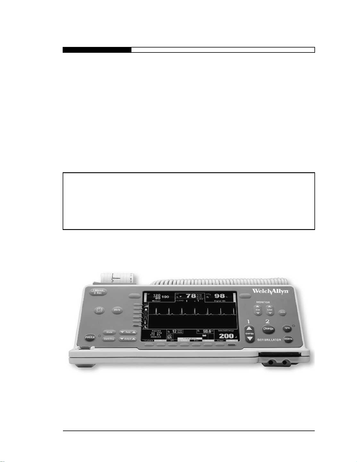
3,&6\VWHP,QWHUIDFHV
1.
System power switch
Switch for main system power.
2.
Display
6.5" screen that displays ECG and other parameter
information.
3.
1-Volt output or fax
(optional)
Fax output (optional)
Provides an analog output scaled to 1V output for a
1mV input signal. Used for telemetry radio
transmissions.
Provides fax transmission capability on 12-Lead PIC’s.
4.
RS-232 Data com port
Download the internal log to a computer, external, or
wireless device.
5.
Datacard slot
For system upgrades, data recording and configuring.
6.
Battery slot
Accepts Welch Allyn SmartPak Plus or Welch Allyn
SuperPac batteries
PIC S
YSTEM OVERVIEW
3.2
WELCH ALLYN PORTABLE INTENSIVE CARE SYSTEM
Page 43

PIC S
7.
ECG Patient Cable
Connector
Accepts 3-lead, 5-lead, 12-lead Welch Allyn patient
cables.
8.
Defibrillator
connector
Allows connection of external paddles, or hands-free
adapter.
9.
Defibrillator release
button
Unlocks the defibrillation connector from the
defibrillator, to allow removal of external paddles, or
hands-free adapter.
10.
SpO
2
connector
(optional)
Allows connection of Welch Allyn pulse oximeter
sensors.
11.
CO2 Connector
(optional)
Allows connection of Welch Allyn CO
2
cable or cable
adapter.
12.
Temp connector
(optional)
Allows connection of Welch Allyn temperature probe.
13.
NIBP connector
(optional)
Allows connection of Welch Allyn non-invasive blood
pressure cuffs.
14.
Annotating Chart
recorder
Accepts standard 50 mm paper.
15.
Front panel
Control panel with buttons for PIC System operation.
YSTEM OVERVIEW
NOTE: Only use Welch Allyn patient cables. Excessive
artifact could result.
NOTE: When sliding defibrillation connector, make sure
the release button clicks into place and returns to its up
position.
WELCH ALLYN PORTABLE INTENSIVE CARE SYSTEM
3.3
Page 44

3,&6\VWHP&RQWUROVDQG,QGLFDWRUV
1.
Voice memo
Allows documentation of audio messages.
2.
Print
Activates and deactivates the chart recorder.
3.
Mute
Pressing the
button once causes all
audio alarms and tones to be muted for 90
seconds (except defibrillator charge tones).
4.
Blood pressure
(optional)
Starts or stops cuff inflation.
5.
SpO
2
(optional)
Turns on or off the pulse oximeter.
6.
Size
Selects ECG trace sizes.
7.
Lead
Selects ECG input source.
8.
Hold
Freezes the traces on the display.
9.
Pacer on/off
Turns on/off pacer circuit.
10.
Pacer on/off
indicator
Automatically illuminates during pacing
activity.
PIC S
YSTEM OVERVIEW
3.4
MUTE
WELCH ALLYN PORTABLE INTENSIVE CARE SYSTEM
Page 45

PIC S
YSTEM OVERVIEW
11. Pacer start/stop Delivers pacing stimulus to the patient
or pauses delivering pacing stimulus to
the patient.
12. Pacer mode Changes pacing mode from DEMAND
to ASYNC.
13. Pacer output Selects pacing output current.
14. Pacer rate Selects pacing output rate.
15. Quick access Initiates menu functions appearing adja-
cent to each button on the display when
PIC System is on.
16. Treatment/Configuation controls
Treatment allows documentation of specific treatment summary events and
Configuration allows access to menu
windows.
17. Defib energy select Selects defibrillation energy levels.
18. Defib charge Initiates defibrillator to charge to
selected energy.
19. Defib disarm Disarms charged defibrillator internally.
20. Defib sync Activates the synchronization mode.
21. Sync indicator Light that indicates sync activation.
WELCH ALLYN PORTABLE INTENSIVE CARE SYSTEM
3.5
Page 46

PIC S
When the Semi-Automatic External Defibrillation (SAED) option has
been installed, the PIC can be configured to power up in one of three
modes; SAED Basic, SAED Basic +, Manual defibrillation mode.
Each mode has a unique display and some controls and indicators
may be deactivated (Refer to Defibrillator Controls and Indicators
section). The SAED Basic + mode has been designed to all those BLS
personnel who have completed additional training to assess the
patients vital signs (NIBP and Pulse Ox). In the SAED Basic + mode
the operator would be able to operate the Pulse Oximeter and the
Non-Invasive Blood Pressure. In the SAED Basic mode these
parameters have been disabled to simplify operations.
If the PIC has been configured to power-up in the SAED Basic mode,
only the voice memo (supervisor configurable), chart recorder, hold
and disarm controls will be active. Below is an example of the active
controls and display.
If the PIC has been configured to power-up in the SAED Basic +
mode, the voice memo (supervisor configurable), chart recorder,
hold, blood pressure, SpO
2
, treatment summary and disarm controls
will be active. Below is an example of the active controls and display.
3,&6\VWHP'LVSOD\:LQGRZVDQG0RGHV
SAED Basic Mode
YSTEM OVERVIEW
SAED Basic +
Mode
3.6
WELCH ALLYN PORTABLE INTENSIVE CARE SYSTEM
Page 47

PIC S
If the PIC has been configured to power-up in the Manual
Defibrillation mode, all the controls will be active. Below is an
example of the display.
YSTEM OVERVIEW
Manual Mode
WELCH ALLYN PORTABLE INTENSIVE CARE SYSTEM
3.7
Page 48

3,&6\VWHP'HILEULOODWLRQ3DGGOHV
Standard adult paddles
PIC S
YSTEM OVERVIEW
Deluxe adult paddles (optional)
3.8
WELCH ALLYN PORTABLE INTENSIVE CARE SYSTEM
Page 49

PIC S
1.
Multipurpose Pads
2.
Pad Connector
Connects to patient connector.
3.
Patient Connector
Accepts disposable monitoring /
defibrillation /non-invasive pacing
pads. (Welch Allyn part # 001853)
4.
Multipurpose Hands-Free
Adapter
5.
Shock Button
Hands-free discharge button
6.
Adapter Release Button
Unlocks the adapter connector from
the defibrillator to allow removal.
YSTEM OVERVIEW
3,&6\VWHP'HILEULOODWLRQ+DQGV)UHH
Multipurpose
Hands-Free
Adapter and
Electrodes
(optional)
70
3DGV
WELCH ALLYN PORTABLE INTENSIVE CARE SYSTEM
NOTE: When sliding the multipurpose hands-fr ee adapter on make sure
the release button clicks into place and returns to its up position.
3.9
Page 50

Page 51

HAPTER
y
y
g
C
This chapter describes the ECG Monitoring process including how to use the standard and
4: ECG M
ONITORING
quick access controls and displa
and concludes with a discussion of output options.
Chapter Overview.
• ECG Monitoring Controls and Displays . . . . . . . . . . . . . . . . 4.2
• Quick Access Controls and Displa
• ECG Monitorin
• Outputs . . . . . . . . . . . . . . . . . . . . . . . . . . . . . . . . . . . . . . . . 4.12
CAUTION: First read chapter 1, Saf ety Information, before
s. It provides instructions for conducting ECG monitoring
Operation Procedures . . . . . . . . . . . . . . . . 4.7
proceeding with this chapter.
s . . . . . . . . . . . . . . . . . .4.5
W
ELCH ALLYN PORTABLE INTENSIVE CARE SYSTEM
4.1
Page 52

(&*0RQLWRULQJ&RQWUROVDQG'LVSOD\V
ECG monitoring functions on the PIC System are viewed and
controlled by the highlighted areas illustrated at left.
1.
HR Indicates the Heart Rate Window.
2.
78 BPM
indicates heart rate displayed in beats per minute.
(flashing heart rate indicates an alarm limit has been
exceeded)
3.
ECG abbreviation indicates the origin of the heart rate. In
this case, the source of the heart rate is derived from the
ECG electrodes. The PIC will derive the heart rate from the
optimal source:
Priority 1 =
ECG
electrodes, 2 =
OX
sensor or 3 =
BP
cuff.
4.
Bell symbols in the “Heart Rate window” indicate the status
of the HR alarm: (alarm off), (alarm on), (alarm
upper limit set), (alarm lower limit set), (automatic
HR alarm set).
ECG M
ONITORING
Heart Rate
Window
NOTE: The following description and operation of the ECG
monitoring portion of the PIC System depicts normal factory
default settings. In chapter 13 we will discuss user
configurations of the ECG monitoring system.
4.2
WELCH ALLYN PORTABLE INTENSIVE CARE SYSTEM
Page 53

ECG M
The ECG trace will be replaced with a dotted line and the words
LEAD F AULT
to indicate a lead fault condition. Lead fault condition
maybe occur due to improper connections on the patient cable; lead
wires should be inspected for proper contact and connection. Replace
the electrodes if necessary. In rare cases, an excessive offset voltage
on the ECG electrodes may cause a lead fault condition.
Pressing the
button selects ECG trace sizes from 0.125cm/mv to
4cm/mv and automatic trace sizing. Pressing the up arrow will
increase the ECG size. Pressing the down arrow will decrease the
ECG size. The AUTO size setting will automatically select the proper
gain to fit the ECG in the waveform window. When the PIC is turned
on, the default setting is 1 cm/mv.
ONITORING
Lead Fault
Size
SIZE
Example: Autosize is set and 4cm / mV was selected
Example: Manual size set at 2cm / mV
WELCH ALLYN PORTABLE INTENSIVE CARE SYSTEM
4.3
Page 54

ECG M
Pressing the
button selects the ECG input. Pressing up or down
lead arrows will change the lead selection. If the 3-lead cable is
configured in the display menu, the following lead options are
available:
If the 5-lead cable is configured in the “patient cable” menu, the
above lead selections and the following lead selections are available:
If a paddle set or hands-free adapter cable is connected, the following
additional lead options are also available:
Pressing and holding the
button will freeze the trace(s) in the
trace window. When the hold button is released the traces will
resume. (Chart recorder is not affected by the hold button).
ONITORING
Lead
LEAD
Lead I selected
Lead II selected
Lead III selected
Lead aVR selected
Lead aVL selected
Hold
Lead aVF selected
Lead V selected
Lead paddles selected
Lead pads selected
HOLD
4.4
WELCH ALLYN PORTABLE INTENSIVE CARE SYSTEM
Page 55

ECG M
The quick access volume increases and decreases the volume of the
PIC System. There are four volume settings that can be selected with
each press of the
button.The volume ramp ( ) indicates
the volume level selected.
The quick access global alarm enables or disables all set alarm
parameters. When the PIC System is turned on, the global alarm will
default to the last setting at system shutdown, either enabled ( ) or
disabled ( ).
To enable global alarms, press the
button (1) to
display the alarm on icon ( ). (
).
If the button is not pressed a second time within 10 seconds, global
alarms will automatically revert to enabled ( ). (
).
ONITORING
4XLFN$FFHVV&RQWUROVDQG'LVSOD\V
Volume
Standard Features
Volume
Global Alarm
QRS Beeper
Calibration
Set Heart Rate
Next
VOLUME
Optional Installable Features
Analyze
12 Lead
Log
IBP
CO
2
Back
Alarm
set alarm parameter will be enabled
To disable global alarms
two times. The first press of the button (2) will change the icon
to PUSH TO DISABLE. The second press (3) will change the
alarm icon to OFF ( ).
alarm disabled, all parameter alarms will be disabled
WELCH ALLYN PORTABLE INTENSIVE CARE SYSTEM
GLOBAL ALARM
With the global alarms enabled, any
, press the
GLOBAL ALARM
With the global
button
4.5
Page 56

QRS Beeper Icon
The quick access QRS beeper turns the beeper on and off.
Beeper OFF = Beeper ON =
The quick access calibration control is used to send a calibration
signal to the monitor, chart recorder, 1V and modulated outputs.
The quick access auto heart rate (HR) control is used to set the
automatic HR alarm.
There must be a valid heart rate displayed in the HR window.
To set the automatic HR
alarm limits
, press the quick
access the
button.
The patient’s heart rate, at the
moment the button was
pressed, will be displayed
above the “heart” (
). The
monitor automatically sets the
upper and lower heart rate
alarms, at + 20% of that heart
rate set point or + 10 beats,
whichever is greater. Each
press of the
button
will adjust the heart rate set
point and reset the auto HR
alarm limits.
If an alarm parameter is exceeded, an audible tone will sound and the
heart rate will flash.
If there is no heart rate in the HR window, the upper and lower heart
rate limits will be undetermined and the “set heart rate icon” (
)
will appear.
Calibration Icon
Auto Heart Rate
NOTE: Cal button is disabled in x4 gain setting.
ORDER TO SET THE AUTO
IN
ALARM LIMITS
HR
ECG M
:
ONITORING
AUTO HR
AUTO HR
4.6
WELCH ALLYN PORTABLE INTENSIVE CARE SYSTEM
Page 57

ECG M
1.
Press
switch on. Set the
to
PDL (paddles).
2.
Apply gel to paddles and place the sternum
paddle firmly against the patient’s chest
inferior to the right clavicle and lateral to the
upper sternum; place the apex paddle in the
anterior-axillary line, inferior and lateral to
the patient’s left nipple, as shown to the right.
3.
Observe the patient‘s electrocardiogram
on the display. Adjust size of the ECG
trace with the
control button as
necessary.
1.
Press
switch ON.
2.
Insure that the display indicates a 3-lead
patient cable has been configured. If not, see
chapter 13 for setting patient cable.
3.
Thoroughly prep patient skin for electrode
attachment. Clean and dry skin sites
preferably with a coarse, dry terry cloth.
Next, clean skin with alcohol and allow to
dry completely before applying pads.
4.
Connect each lead of the 3-lead patient cable
to the appropriate disposable electrode.
Arrange the electrodes as shown to the right.
(Make sure that the ECG electrodes are
placed to allow defibrillation if necessary).
ONITORING
(&*0RQLWRULQJ2SHUDWLRQ3URFHGXUHV
ONITORING WITH DEFIBRILLATOR PADDLES
M
Paddle Placement
POWER
NOTE: The type of electrode and the technique used in preparing the
skin are major factors in determining the quality of the ECG
signal obtained. Use high-quality, silver-silver chloride
electrodes. These electrodes are designed to provide excellent
baseline stability, rapid recovery from defibrillation, and
minimize artifact from patient movement. Do not use electrodes
if gel is dry.
SIZE
LEAD
3-Lead Electrode Placement
ONITORING WITH
M
EAD PATIENT CABLE
3 L
POWER
WELCH ALLYN PORTABLE INTENSIVE CARE SYSTEM
4.7
Page 58

5.
Insert the patient cable plug into the input ECG connector on
the PIC System.
6.
Select the proper lead setting for the desired lead
configuration by pressing the
LEAD
button to the appropriate
position: I, II, or III.
7.
Observe the patient‘s electrocardiogram on the display.
Adjust size of the ECG trace with the
button as
necessary.
1.
Press
switch ON.
2.
Insure that the display indicates a 5-lead patient cable has
been configured. If not, see chapter 13 for setting patient
cable.
3.
Thoroughly prepare patient skin for electrode attachment.
Clean and dry skin sites preferably with a coarse, dry terry
cloth. Next, clean skin with alcohol and allow to dry
completely before applying pads.
4.
Connect each lead of the 5-lead patient cable to the
appropriate disposable electrode. Arrange the electrodes as
shown below. (Make sure that the ECG electrodes are
placed to allow defibrillation if necessary).
5.
Insert the patient cable plug into the input ECG connector
on the PIC System.
6.
Select the proper lead setting for the desired lead
configuration. Press the
button to the appropriate
position corresponding to the desired configuration.
7.
Observe the patient‘s electrocardiogram on the display.
Adjust size of the ECG trace with the
button as
necessary.
SIZE
ECG M
ONITORING
ONITORING WITH
M
POWER
LEAD PATIENT CABLE
5-
LEAD
SIZE
4.8
WELCH ALLYN PORTABLE INTENSIVE CARE SYSTEM
Page 59

ECG M
ONITORING
5-Lead Electrode Placement
5-Lead Electrode Placement
Color lead Location
AHA IEC
Green (RL) Black (N) Right mid-clavicular line, between 6th and 7th
intercostal space
Red (LL) Green (F) Left mid-clavicular line, between 6th and 7th
intercostal space
White (RA) Red (R) Right mid-clavicular line, directly below clavicle
Black (LA) Yellow (L) Left mid-clavicular line, directly below clavicle
Brown (V) White (C) Chest - Place per figure at left for V1-V6
V1 - 4th intercostal space at right sternal
margin
V2 - 4th intercostal space at left sternal margin
V3 - Midway between V2 and V4 leads
V4 - 5th intercostal space at mid-clavicular line
V5 - Same transverse level as V4 at left
anterior-axillary line
WELCH ALLYN PORTABLE INTENSIVE CARE SYSTEM
V6 - Same transverse level as V4 at left midaxillary line
4.9
Page 60

ECG M
1.
Press
switch ON. Press the
button to the PAD
position.
2.
Connect the disposable
defibrillation pads to the
hands-free adapter cable.
3.
Remove or loosen clothing
if necessary for application
of pads. Clean and dry skin
sites preferably with a
coarse, dry terry cloth.
4.
Check expiration date on
the multipurpose pads
package. Remove
multipurpose defibrillation
pads from packaging.
Remove the protective
cover and apply the pads to
the patient in the position illustrated here. Do not use if gel area
is dry.
5.
When applying pad, gently adhere opposite edge of pad to
patient and lightly roll pad against patient’s skin.
6.
Observe the patient’s electrocardiogram on the monitor scope.
7.
Adjust
control as necessary.
ONITORING
ONITORING WITH
M
CAUTION: Be sure that the hands-free adapter is firmly seated in
the defib connector before monitoring with “handsfree” defibrillation pads.
CAUTION: Use only R2 multifunction pads with Welch Allyn hands-
free adapter. Do not connect R2 ECG sets to the Welch
Allyn hands-free adapter; an ECG will not be obtained.
POWER
ANDS-FREE
“H
EFIBRILLATION PADS
” D
LEAD
SIZE
Hands-Free Pad Placement
NOTE: Apex-anterior or apex-posterior placement of pads results in
a modified Lead II ECG trace.
4.10
WELCH ALLYN PORTABLE INTENSIVE CARE SYSTEM
Page 61

ECG M
1.
Press
switch ON.
2.
Insure that the display indicates 3-lead
patient cable has been selected.
3.
Attach the black and red leads of the
standard 3-lead patient cable to the dual
contact Welch Allyn BITRODE
®
by
snapping the clip on the lead over the lead
terminals. Similarly, attach the white lead
to the single-contact Welch Allyn
BITRODE
®
. Press the
button to
select the LEAD I or LEAD II position.
4.
Squeeze a small amount of Welch Allyn 2051
ELECTRODE GEL onto the contact area on the inner
portion of each limb clip, or apply Welch Allyn 2052
KLEAN TRACE on the patient’s arms where the Welch
Allyn BITRODE
®
contact will be placed.
5.
Place the dual-contact clip on the patient’s left wrist, or on
the forearm if the wrist is not large enough to provide
adequate clamping force by the Welch Allyn BITRODE
®
.
Place the single-contact clip on the patient’s right inner
wrist (or inner forearm if necessary). Make sure that the
clips and arms are positioned and attached so minimum arm
movement is allowed, to preclude possible artifact on the
display. This will give a Lead I ECG.
ONITORING
ONITORING WITH WELCH ALLYN
M
BITRODE®
POWER
LEAD
BITRODE
®
NOTE: If a weak signal is being obtained up in above configuration
(Lead I), then the dual contact Welch Allyn BITRODE® can
be placed on left ankle to monitor in Lead II Mode.
WELCH ALLYN PORTABLE INTENSIVE CARE SYSTEM
4.11
Page 62

2XWSXWV
Provides an analog ECG output scaled to 1 Volt out for a 1mV input
signal. The 1V output is routinely used to transmit ECG over
telemetry . The frequency response of the output signal will match the
display frequency response selection, except that the upper frequency
limit will be 100 Hz.
1 Volt Output (optional)
ECG M
ONITORING
4.12
WELCH ALLYN PORTABLE INTENSIVE CARE SYSTEM
Page 63

(
y
g
g
g
g
HAPTER
C
This chapter describes the controls, displays and operation of the Basic 12-lead option. It
5: 12-
LEAD
ONITORING
M
OPTIONAL
)
includes a discussion of the basic 12-lead controls and displa
patient ID information, and monitorin
Chapter Overview:
• Basic 12-Lead Monitoring Controls and Display . . . . . . . . .5.2
• Enterin
• Monitorin
• Active 12-Lead Monitorin
• Quick Access Functions of the Active 12-Lead Mode . . . . .5.11
CAUTION: First read chapter 1, Safety Information, before
NOTE: Before reading this chapter review chapter 4, ECG
procedures.
Patient ID Information . . . . . . . . . . . . . . . . . . . . . . 5.4
In Normal 12-Lead Mode . . . . . . . . . . . . . . . . . .5.7
Controls and Displays . . . . . . . .5.8
proceeding with this chapter.
monitoring, to familiarize yourself with basic ECG
monitoring controls, displays and operation procedures.
s, the process for entering
W
ELCH ALLYN PORTABLE INTENSIVE CARE SYSTEM
5.1
Page 64

12-
The illustration above highlights the areas that are used to operate the
12-lead option, if it is installed in the PIC System. If needed refer to
chapter 4 for basic ECG monitoring information.
When the 12-lead patient cable is connected the following lead
options are available by pressing the
button:
LEAD MONITORING (OPTIONAL
%DVLFOHDG0RQLWRULQJ&RQWUROVDQG'LVSOD\
)
Lead Selection
NOTE: The following description and operation of the 12-lead
portion of the PIC System depict normal factory default
settings.
LEAD
5.2
WELCH ALLYN PORTABLE INTENSIVE CARE SYSTEM
Page 65

12-
The Basic 12-lead waveform window can display either 1, 2 or 3
traces.
To add or remove traces from the waveform window access the trace
menu by pressing
–>
–>
in the treatment
summary menu.
Once in the Trace Menu you can select the waveform you would like
displayed in waveform windows 2 or 3. Selectable options include
Resp, Pleth, I, II, III, aVR, aVL, aVF, V1, V2, V3, V4, V5, V6 and
OFF. Pressing
will display your selection in the highlighted
waveform window.
If the 12-lead option is installed a icon will appear at the
bottom of the quick access window (see below). All other quick
access controls function as described on page 4.5.
LEAD MONITORING (OPTIONAL
Waveform Window
)
12-lead Quick
Access Functions
Volume
SAVE
NOTE: Pressing the
displayed ECG lead in waveform 1 window only.
NEXT
LEAD
DISPLAY
button will allow the user to select the
TRACES
Global Alarm
QRS Beeper
Calibration
Set Heart Rate
Next
WELCH ALLYN PORTABLE INTENSIVE CARE SYSTEM
Quick access controls
12 Lead
5.3
Page 66

(QWHULQJ3DWLHQW,'LQIRUPDWLRQ
The operator can enter specific information about each individual
patient such as Name, Age, Sex and an identifier code to be used for
documentation.
T o begin, press the "
" button of the quick access window to display
the Patient ID menu.
The defaults for the Patient ID menu
are:
Name: John Doe
Age: 40
Sex: M
Identifier: today's date followed by
the time and serial number
(mmddyyhhmm000000).
1.
Press the
button (A). The Name menu appears giving
the operator the option of moving the cursor forward or
backward; or clearing, canceling or saving the entry.
2.
Enter a new name by pressing once on the group of characters
containing the letter of your choice (B). The menu will be
replaced with a menu displaying the individual letters “P-Q-
R-S-T.” (In this case we want to change the "J" to an "S").
Patient
Information
12
12-
LEAD MONITORING (OPTIONAL
)
NTERING PATIENT’S NAME
E
NAME
NOTE: After pressing the name button the treatment window options
are re placed by an alpha/numeric window. The default name
"John Doe" is displayed just above the alpha/ numeric
window with an active cursor highlighting the first letter of
the name.
5.4
WELCH ALLYN PORTABLE INTENSIVE CARE SYSTEM
Page 67

12-
3.
Next, press on the actual character (C). Your selection will be
entered and the cursor will move to the next letter in the
name. Continue this procedure to complete the name.
4.
Pressing the
button in the Name menu will save the
name selection and return to the patient ID menu.
1.
Press the
button to
display the Age/Sex Menu.
2.
Pressing the up or down arrows
will increase or decrease the
displayed number by increments
of 5, from 15 to 100.
3.
Press the
button to toggle
between “M” for male and F for
female.
4.
Once the age/sex is selected, press
to return to the
Patient ID menu.
The PIC System 12-lead automatically gives each patient a unique
identifier that is comprised of the current date, time and the unit serial
No. at which monitoring began. The operator can change the
automatic patient identifier by following the instructions below.
1.
Press the
button (A). The Identifier menu appears in
place of the Patient ID menu and the Treatment Summary
window is replaced with the Alpha/Numeric window. The
LEAD MONITORING (OPTIONAL
)
SAVE
NTERING PATIENT’S AGE/SEX
E
NOTE: The Default setting on patient’s age is 40.
AGE/SEX
SEX
BACK
NTERING A NEW PATIENT IDENTIFIER
E
IDENTIFIER
WELCH ALLYN PORTABLE INTENSIVE CARE SYSTEM
5.5
Page 68

12-
operator has the option of moving the cursor forward or
backward; or clearing, canceling or saving the entry.
2.
Using the Alpha/Numeric window options enter a new character
by pressing once on the group of characters containing character
of your choice (B). (In this case we want to change the first
character of the identifier, "1", to a "0")
3.
Then press on the actual character (C). Your selection will be
entered and the cursor will move to the next character in the
identifier. Continue this procedure to complete the name.
4.
Pressing the
button in the Identifier Menu will save the
selection and return to the patient ID menu.
LEAD MONITORING (OPTIONAL
NOTE: After pressing the identifier button the treatment summary
window options are replaced by an alpha/numeric window.
The default Identifier "Date and time" is displayed just above
the alpha/ numeric window with an active cursor in the first
space of the identifier code.
)
SAVE
5.6
WELCH ALLYN PORTABLE INTENSIVE CARE SYSTEM
Page 69

12-
Basic 12-lead mode is the default start up mode of the PIC System if
the 12-lead option is installed and the 12-lead cable is connected. In
this mode the operator will be able to view each of 12-leads in the
waveform window.
1.
Press the PIC System's
switch on.
2.
The lead window will automatically sense the type of patient
cable inserted into the PIC System. Check the lead window to
insure that the display indicates a 12-lead patient cable is
inserted into the patient connector.
3.
Thoroughly prep patient skin for electrode attachment. Clean
and dry skin sites preferably with a coarse, dry terry cloth.
Next, clean skin with alcohol and allow to dry completely
before applying pads.
4.
Connect each lead of the 12-lead patient cable to the
appropriate disposable electrode. Arrange the electrodes as
shown on page 4.7. (Make sure that the ECG electrodes are
placed to allow defibrillation if necessary).
5.
Observe the patient‘s electrocardiogram on the
.
Adjust size of the ECG trace with the
button as
necessary.
6.
The displayed lead in the waveform 1 window can be
selected by pressing the
button.
LEAD MONITORING (OPTIONAL
)
0RQLWRULQJLQ1RUPDO/HDG0RGH
POWER
LEAD
DISPLAY
SIZE
WELCH ALLYN PORTABLE INTENSIVE CARE SYSTEM
5.7
Page 70

12-
The Active 12-lead Mode is an easy way of analyzing, storing and
transmitting 12-lead data. This mode is a useful tool when there is a
need for more in-depth information about the patient’s cardiac
condition. The Active 12-lead Mode acquires and analyzes
10 seconds of 12-lead ECG. Once acquired, the operator can view the
ECG on the PIC System's display, along with a real-time trace of each
lead.
1.
Press the PIC System's
switch on.
2.
The PIC will automatically sense the type of patient cable
inserted into the PIC system. Check the lead window to
insure that the display indicates a 12-lead patient cable is
inserted into the patient connector.
3.
Press the
button (A) on the quick access window. This
will display the Patient ID menu and change the waveform
window to display 3 traces. The display initially displays
leads I, II, III. The frequency response in Active 12-lead
mode will be set to either diagnostic (.05-150 Hz) or filtered
diagnostic (.25 - 40 Hz) as configured in the supervisor menu
.
4.
Acquire New 12-Lead Snapshot
a
Press the
button (B). This will enter you into
the Active 12-lead Mode. The PIC System will begin
storing 10 seconds of 12-lead ECG information. The
word ACQUIRING will blink in the waveform window
and the quick access window will blank except for a
stop icon at the bottom.
LEAD MONITORING (OPTIONAL
$FWLYHOHDG0RQLWRULQJ&RQWUROVDQG'LVSOD\V
)
Monitoring in
Active 12-lead
Mode
NTERING THE ACTIVE
E
12
LEAD MODE
12-
POWER
ACQUIRE
5.8
WELCH ALLYN PORTABLE INTENSIVE CARE SYSTEM
Page 71

12-
b.
After approximately 10 seconds, the PIC System will
prompt the user that it has completed acquisition. A
snapshot and real-time window will appear, each show-
ing leads I, II, and III. The Quick access window will
have also changed to display Analysis, Save, Fax, Print,
Page, and Back icons.
Press the
button. If at least one 12-Lead
snapshot is in the internal log, the 12-Lead Log Review menu will
display which allows selecting from the 10 most recent acquired
snapshots.
If
is pressed, the presently selected snapshot from the internal
log will be drawn on the screen for review. The quick access window
will change to display analysis, save, send, print, page and back icons.
LEAD MONITORING (OPTIONAL
)
Review old 12-lead
Snapshot
NOTE: To stop 12-lead acquisition, press the
patient ID menu will appear.
LEAD LOG REVIEW
12-
button and the
STOP
NOTE: The most recent snapshot header information is displayed
initially in the 12-Lead Review Menu.
VIEW
NOTE: If more than 10 snapshots are stored, the oldest snapshots will
be overwritten.
WELCH ALLYN PORTABLE INTENSIVE CARE SYSTEM
5.9
Page 72

Active 12-lead
y
After the PIC system has either acquired a new 12-Lead snapshot,
or reviewed an old 12-Lead snapshot from the internal log the
display is divided into a SNAPSHOT window on the left and a real-
time ECG window on the right. The snapshot window first displays
3.33 seconds of stored information from leads I, II, and III. The
real-time window will display a real-time trace of the corresponding
leads I, II, and III.
The snapshot of each lead is 10 seconds in duration. The snapshot
window displays 3.33 seconds of each of 3 leads at a time. Each
snapshot consists of 3 pages of 3.33 seconds of ECG.
a)
Leads I, II, III are displayed first in page one of the snapshot
window.
b)
To scroll through the other 9 leads, press the up or down
arrow button. The same 3.33 seconds of ECG for the
next set of 3 leads will be displayed.
c)
To go to page two of the snapshot window and view the next
3.33 seconds of ECG information, press the
button in
the quick access window.
Displa
12-
LEAD MONITORING (OPTIONAL
)
IEWING THE SNAPSHOT INFORMATION
V
LEAD
PAGE
5.10
WELCH ALLYN PORTABLE INTENSIVE CARE SYSTEM
Page 73

12-
After the PIC system has acquired the 12-lead information the
operator can use the quick access functions to review, store, and
transmit data to a remote location by pressing any of the quick access
buttons.
Analyze Function
If installed, the analyze function displays the diagnostic
results of the acquired 12-lead ECG. See chapter 18 for
details and instructions for 12-lead interpretive analysis.
Save Function
If a data card is installed, pressing the save button will
download the acquired 12-lead information to the PIC
System’s PCMCIA data card.
Autosave Function
If a data card is installed, printing or faxing a 12-lead
snapshot will automatically save the snapshot to the
datacard. An “S” will appear on the save icon indicating
that the current snapshot has been saved.
LEAD MONITORING (OPTIONAL
)
4XLFN$FFHVV)XQFWLRQVRIWKH$FWLYHOHDG0RGH
NOTE: Each 12-lead snapshot is automatically saved to the internal
log in a rotary queue which stores the 8 most recent
snapshots.
WELCH ALLYN PORTABLE INTENSIVE CARE SYSTEM
5.11
Page 74

12-
Send Function
Optional functions for the
remote transmission of 12-lead
ECG data include fax,
Mobitex, and Cellular.
If the fax option is purchased, the fax output cable (001949)
must be connected to the fax output jack and to a wall
phone jack or to the cellular phone adapter (900241) before
initiating a fax operation.
1.
Select the page (1, 2, or 3) of ECG data to fax (See page
function on the following page).
2.
Press the
button. A selection of 12 previously
programmed phone numbers and 4 user programmed
numbers will be displayed.
If the user dial menu, on the 4th menu page is selected, a
alpha numeric entry menu will be displayed on the bottom of
the screen. The user can enter a phone number using the
technique described previously in this chapter.
3.
Press the appropriate location/phone number to send the
stored 12-lead data or press
to display the next
page of phone numbers.
LEAD MONITORING (OPTIONAL
NOTE: Transmission time after connecting will be approximately
1 minute 40 seconds at 9600 baud. This time will be slightly
longer if a datacard is installed.
Send
Fax
Mobitex
Cellular
NOTE: For instructions on Mobitex and
Cellular operation see Chapter 19.
Exit
)
PERATION OF THE FAX FUNCTION
O
FAX
Complete
:
NEXT PAGE
5.12
WELCH ALLYN PORTABLE INTENSIVE CARE SYSTEM
Page 75

12-
4.
A sequence of status messages consisting of Initializing,
Dialing, Connecting, sending, 20%, 40%.....100%, Complete,
will display in the box of the number that was selected. A fax
transmission summary will be printed on the chart recorder
and stored in the log.
Print Function
Pressing the print button will print 3 seconds of each
lead in groups of three, along with the patient ID
information. Select the desired page (1, 2, or 3) of ECG
data before printing.
Page Function
This functions allows the operator to view 3 snapshot
pages of 12-lead ECG data. See previous section,
"Viewing the Snapshot Information."
LEAD MONITORING (OPTIONAL
)
NOTE: Fax transmission pho ne numb e rs are entered in the
Supervisor Menu. See chapter 13.
NOTE: The format of the 12-lead print-out can be changed from the
Supervisor>12-Lead>Printer menu. The print-out shown
above is the default 3x4 I/II/III format.
WELCH ALLYN PORTABLE INTENSIVE CARE SYSTEM
5.13
Page 76

Page 77

HAPTER
g
C
This chapter describes the manual mode defibrillator controls and displays. It provides
6: M
ANUAL
EFIBRILLATION
D
operatin
purpose hands-free adapter.
Chapter Overview:
instructions for manual defibrillation and using external paddles and the multi-
• Manual Defibrillator Controls and Displays . . . . . . . . . . . . .6.2
• Manual Defibrillation Operation Procedures . . . . . . . . . . . .6.5
CAUTION: First read chapter 1, Safety Information, before proceeding
NOTE: The unit has an automatic defibrillator disarm mode. If energy is
with this chapter.
not delivered to a patient or load, an internal timer will disarm
the defibrillator after 1 minute in manual mode.
W
ELCH ALLYN PORTABLE INTENSIVE CARE SYSTEM
6.1
Page 78

M
Defibrillation functions on the PIC System are viewed on and
controlled by the areas illustrated above.
When the PIC System is turned on the
default selected energy is displayed (
200 J
,
as illustrated at left). The defibrillator is not
charged.
CONNECT PADDLES in the defibrillator
window indicates the defibrillator paddles
or multipurpose hands-free adapter are not
attached or are not seated firmly in the
defibrillator connector.
ANUAL DEFIBRILLATION
0DQXDO'HILEULOODWRU&RQWUROVDQG'LVSOD\V
Initial Displays
NOTE: The following operations of th e defibrillator depict normal
factory default settings. In chapter 13 we will discuss user
configurations of the defibrillator.
6.2
WELCH ALLYN PORTABLE INTENSIVE CARE SYSTEM
Page 79

M
The
button is used to select defibrillator energy.
Pressing either the up or down arrow will cause the Energy Range Bar
to be displayed on the right side of the display.
The
button initiates the defibrillator charge. When the
charge button is pressed, a periodic audible tone will sound; the
energy range bar graph will highlight the relative charge state until it
reaches the selected energy.
When the defibrillator is fully charged, the periodic tone will change
to a continuous tone and the highlighted energy range bar graph will
include the selected energy.
ANUAL DEFIBRILLATION
Energy Select
ENERGY SELECT
Energy Range Bar
NOTE: The default energy level, upon power start up, can be changed to
a lower or higher setting. See Configuring the Defibrillator
(supervisor menus) later in this chapter.
Charge
CHARGE
NOTE: If the energy selection is changed during the charge sequence,
the unit will automatically charge to the new energy level and the
display will be updated accordingly.
Charging - - - - - - - - - - - - - - - - - - - - - - - - - - - - - - - - - - - - - - - - - - - - - -> Fully Charged
WELCH ALLYN PORTABLE INTENSIVE CARE SYSTEM
6.3
Page 80

M
Pressing the
button will safely discharge the defibrillator
internally and the energy range bar display will disappear.
Pressing the
button activates the synchronization mode and
illuminates the SYNC indicator light, which flashes off when a QRS
has been detected. Sync will appear on the display and a SYNC
marker will also appear over the portion of the ECG that the
defibrillator will trigger on. Pressing the
button again reverts to
the asynchronous mode.
ANUAL DEFIBRILLATION
Disarm
Sync
DISARM
NOTE: Note: The unit contains an automatic disarm of the defibrillator,
If the operator has not delivered the energy to a patient or load,
an internal timer will disarm the defibrillator after 1 minute
when in manual mode.
SYNC
SYNC
6.4
NOTE: After synchronized cardioversion discharg e, the defibrillator can
be configured to remain in the Sync mode or revert to the
asynchronous mode (See configuring the defibrillator
[Supervisor Menus] in chapter 13).
NOTE: The factory default Sync setting after discharge is the
asynchronous mode.
WELCH ALLYN PORTABLE INTENSIVE CARE SYSTEM
Page 81

M
1.
Press
switch to ON.
2.
Apply electrode gel to the center of one paddle electrode.
Lightly press the paddle electrodes together and spread the
gel evenly over both paddle surfaces. Make sure gel covers
the entire paddle surface. Do not allow any gel to touch the
paddle handle or the operators hands.
3.
Press the
button on the front panel up or
down to select the desired energy level (energy selection is
also available on the deluxe paddle set).
4.
Pressing the
button on the defibrillator panel to
charge the defibrillator (charge selection is also available on
the deluxe paddle set). An audible periodic tone will sound
indicating that the unit is charging. The energy range bar
graph on the right side of the display will highlight the
relative charge state until it reaches the selected energy.
When the unit is fully charged, the periodic tone will change
to a continuous tone and the highlighted energy range bar
graph will include the selected energy.
5.
Place the sternum paddle firmly against the patient’s chest
inferior to the patient’s right clavicle and lateral to the upper
sternum; place the apex paddle in the anterior-axillary line,
inferior and lateral to the patient’s left nipple, as shown below.
ANUAL DEFIBRILLATION
0DQXDO'HILEULOODWLRQ2SHUDWLRQ3URFHGXUHV
Defibrillation with
External Paddles
POWER
NOTE: If the selected energy is changed after charging has been
activated, additional time may be required to charge to the new
energy.
ENERGY SELECT
CHARGE
WELCH ALLYN PORTABLE INTENSIVE CARE SYSTEM
Paddle Placement
6.5
Page 82

M
6.
With the paddles in proper position, clear all personnel;
visually ensure all personnel are clear (including the
operator) from patient contact. Press the button on each
paddle simultaneously.
7. Observe the effect of the delivered
countershock by observing the patient’ s ECG
on the display. The amount of energy
delivered will appear in the defibrillation
display window. Verify that the proper
amount of energy has been delivered.
8.
For additional countershocks, repeat steps 3-8.
9.
T o secure the instrument, turn the power switch to Off. Clean
the paddle electrodes, patient cables and controls as outlined
in chapter 16.
10.
If battery power was used, recharge the battery by connecting
the unit to AC power, or replace the used battery with a fresh,
fully charged battery and check that there are sufficient
supplies for the next use (defib gel, recorder paper, ECG
electrodes, etc.).
Connect the multipurpose hands-free adapter by sliding it onto the
defibrillator connector track. Make sure the release button clicks into
place and is in the up position.
1.
Press
switch to ON, and ensure lead selector i s set to
PAD.
2.
Remove or loosen patient’s clothing if necessary for
application of pads. Clean and dry skin sites, preferably with
a coarse, dry terry cloth. Shave patient if appropriate. To
remove lotions or moisturizer clean patient’s skin with
alcohol and allow to dry completely before applying pads.
ANUAL DEFIBRILLATION
NOTE: If defibrillation is not required, pressing the
located on the front panel will discharge the energy int e rnally.
Delivered Energy
NOTE: For monitoring through the defibrillator paddles, the ECG
waveform can be monitored immediately after the FIRE buttons
are re lea sed , as lon g as the paddles are held in place, and the
LEAD select is set to PDL (Paddles).
DISARM
button
Defibrillation with
Multipurpose
Hands-Free
Adapter
6.6
POWER
WELCH ALLYN PORTABLE INTENSIVE CARE SYSTEM
Page 83

M
3.
Check expiration date; do not use pads that have expired.
Remove disposable multipurpose pads from packaging. Use
Welch Allyn multipurpose electrodes model 001853 for adult
patients, pediatric multipurpose electrodes model 001828 for
pediatric patients (<10kg). Remove the protective co ver from the
pads and apply the pads to the patient in the position illustrated
below or according to pad package. Do not use if gel area is dry.
4.
Press the
button on the front panel up or
down to select the desired energy level.
5.
Pressing the
button on the defibrillator panel to char ge
the defibrillator. An audible tone will sound periodically
indicating that the unit is charging. The energy range bar on the
right side of the display will highlight the relative charge state
until it reaches the selected energy. When the unit is fully
charged, the periodic tone will change to a continuous tone and
the highlighted energy range bar will include the selected energy.
6.
V isually and verbally ensure that all personnel (including the
operator) are clear from the patient. Press the button on the
multipurpose hands-free adapter to deliver energy.
7.
Observe the effect of the delivered countershock by observing
the patient’s ECG on the display. The amount of energy
delivered will appear in the defibrillation display window.
Verify that the proper amount of energy has been delivered.
8.
For additional countershocks, repeat steps 4 through 8.
9.
T o secure the instrument, turn the power switch to Off. Clean
the patient cables and controls as outlined in Chapter 16.
10.
If battery power was used, recharge the battery by connecting
the unit to AC power, or replace the used battery with a fresh,
fully charged battery and check that there are sufficient
supplies for the next use.
ANUAL DEFIBRILLATION
ENERGY SELECT
CHARGE
Hands-Free
Pad Placement
WELCH ALLYN PORTABLE INTENSIVE CARE SYSTEM
6.7
Page 84

M
1.
Press
switch to ON.
2.
Attach an ECG electrode to each lead of the patient cable.
Attach the electrodes to the patient. Position the electrodes to
allow immediate placement of the defibrillator paddles.
3.
Connect the ECG patient cable to the ECG input connector.
Press the
button to select lead II position (if using the
hands-free defibrillator pads, select PAD lead position). If
using 5-lead patient cable (see chapter 13 to change 3-lead
selection to 5-lead) select lead II position. Observe the
patient’s ECG on the display.
4.
Apply electrode gel to the center of one paddle electrode.
Lightly press the paddle electrodes together and spread the
gel evenly over both paddle surfaces. Make sure the gel
covers the entire paddle surface. Do not allow any gel to
touch the paddle handle or the operator hands.
5.
Press the
button to engage the synchronizer. The light
next to the Sync button will illuminate and an “S” marker
will appear over the portion of the ECG that the defibrillator
will trigger on. The Sync light will flash off with each Sync
marker.
ANUAL DEFIBRILLATION
W ARNING: Elective cardioversion should only be performed while
monitoring patient with patient cable and electrodes
or hands-free defibrillator pads. Although the device
will allow synchronized cardioversion in the PDL
(paddle) lead selection, it is not recommended that
Sync be performed in the PDL lead. Artifact can be
generated from the paddle cables, which could cause
the defibrillator to discharge on the artifact.
Performing
Synchronized
Cardioversion
POWER
LEAD
Electrode Placement
SYNC
6.8
WELCH ALLYN PORTABLE INTENSIVE CARE SYSTEM
Page 85

M
6.
Press
button on the front panel up or down
to select the desired energy level.
7.
Charge the defibrillator by pressing the
button on
the defibrillator panel, or the
button on the deluxe
apex paddle. An audible tone will sound periodically,
indicating that the unit is charging. The energy range bar on
the right side of the display will highlight the relative charge
state, until it reaches the selected energy. When the unit is
fully charged, the periodic tone will change to a continuous
tone and the highlighted energy range bar will include the
selected energy.
8.
Place the sternum paddle firmly against the patient’s chest
inferior to the patient’s right clavicle and lateral to the upper
sternum; place the apex paddle in the anterior-axillary line,
inferior and lateral to the patient’ s left nipple, as shown to the
right.
9.
T o dischar ge, hold the padd les firmly in place, then press and
hold both
buttons down until the defibrillator
discharges.
ANUAL DEFIBRILLATION
NOTE: If the marker pulse does not appear over the R wave, turn lead
select to another position (I, II, III) or adjust ECG size. If the
Sync marker is not obtained, the defibrillator will not discharge.
Do not switch the lead from PADS if monitoring with hands-free
defibrillation pads.
ENERGY SELECT
CHARGE
CHARGE
NOTE: Discharge may not be immediate upon pressing the paddle
buttons. This is normal. Keep the fire buttons depressed until the
defibrillator discharges.
NOTE: For any additional shocks, the
need to be pressed. This depends on the supervisor cardioversion
mode setting.
WELCH ALLYN PORTABLE INTENSIVE CARE SYSTEM
Cardioversion Paddle Placement
DISCHARGE
SYNC
button may or may not
6.9
Page 86

10.
To negate the cardioversion after the buttons are pressed
but before the next QRS wave is detected and the defibrillator
discharges, merely release both
buttons. The
defibrillator will not fire. When ready to defibrillate again,
firmly position the paddles, then press and hold the
buttons until a QRS wave is detected and the
defibrillator delivers the energy.
11.
Press the
button on the front panel to disarm
defibrillator at any time during procedure.
Defibrillation with
1.
Shut the unit off before attaching the pediatric electrodes to
the paddles.
2.
Slide the pediatric electrode onto the adult paddle set. Be sure
to slide the electrode in the end for a snug fit.
3.
Follow instructions for defibrillating with external paddles to
defibrillate patient.
Pediatric Adapter
DISCHARGE
DISARM
M
ANUAL DEFIBRILLATION
DISCHARGE
CAUTION:
NOTE: To facilitate rapid defibrillation for pediatric use, the power on
There is no energy lim it for pediatric electrodes. Care
should be exercised to insure appropriate selection of
defibrillation energy level for pediatric patients.
default defibrillation energy can be auto set in the supervisordefib menu.
NOTE: Pediatric defibrillation research has shown that adult paddles
should be used as soon as chest size permits.The larger paddle
size has been found to help decrease transthoracic impedance,
thus facilitating cardioversion and defibrillation.
6.10
Pediatric Electrodes
WELCH ALLYN PORTABLE INTENSIVE CARE SYSTEM
Page 87

HAPTER
g
C
7: S
EMI
UTOMATED
-A
XTERNAL
E
(
EFIB
D
This chapter describes the functions and operation of the Semi-Automated External
Defibrillation (SAED) unit, includin
Chapter Overview:
OPTIONAL
)
using Multipurpose Hands-Free Pads and Paddles.
• SAED Basic Mode . . . . . . . . . . . . . . . . . . . . . . . . . . . . . . . . 7.2
• SAED Basic+ Mode . . . . . . . . . . . . . . . . . . . . . . . . . . . . . . . 7.6
• SAED Operation Procedures . . . . . . . . . . . . . . . . . . . . . . . . 7.7
• EMS Mode . . . . . . . . . . . . . . . . . . . . . . . . . . . . . . . . . . . . . .7.8
• SAED Mode Operation with Multipurpose
Hands-Free Pads . . . . . . . . . . . . . . . . . . . . . . . . . . . . . . . 7.9
• Defibrillation with Paddles while in SAED Mode . . . . . . . . . 7.12
CAUTION: First read chapter 1, Safety Information before
proceeding with this chapter.
NOTE: The unit contai ns an aut omatic disarm of the SAED. If the
operator has not delivered the energy to a patient or load, an
internal timer will disarm the defibrillator after 30 seconds.
W
ELCH ALLYN PORTABLE INTENSIVE CARE SYSTEM
7.1
Page 88

6$('%DVLF0RGH
When the Semi-Automatic Defibrillation (SAED) option has been
installed, the PIC can be configured to power up in either SAED
Basic, SAED Basic+, or Manual defibrillation mode.
If the PIC has been configured to power-up in the SAED Basic mode,
only the controls that have been highlighted below will be active. All
other controls will be disabled to simplify operations.
Available options in SAED Basic mode are highlighted below:
In the SAED Basic mode, the PIC will continuously monitor the
patient’s ECG and determine if a shockable rhythm is present. When
a shockable rhythm is detected, the PIC will automatically select the
appropriate energy (based on the energy protocol selected in the
Supervisor configuration menu), and automatically charge the
defibrillator to the selected energy. After three consecutive No Shock
analysis results, the PIC will display text and provide a voice prompt
to “Check Pulse, If no pulse start CPR.” After each set of three
consecutive defibrillation attempts the PIC will provide the same text
and voice prompts and enter into CPR mode when the (Analyze)
button and CPR timer displays.
During CPR mode, the PIC System continues to monitor for
shockable rhythms. If a shockable rhythm is detected during CPR
mode, the (Analyze) button will flash. If the operator is
performing CPR, the should be ignored. Pressing the button
will abort the CPR cycle, and analysis cycle will restart.
Defibrillation
Modes
S
EMI-AUTOMATED EXTERNAL DEFIB (OPTIONAL
)
NOTE: The Pulse Oximeter, Non-invasive Blood Pr es sure, Pacer ,
and Treatment Summary menu will not be available in basic
mode.
NOTE: If an ECG rhythm is potentially shockable it may quali fy as
2 No Shock analysis results to hasten entry into CPR mode.
7.2
WELCH ALLYN PORTABLE INTENSIVE CARE SYSTEM
Page 89

S
In the SAED Basic mode, access to the manual defibrillation mode
may be “Locked Out” by a Passcode.
Indicates the SAED Basic mode has been selected and the power on.
Indicates a lead fault condition. Neither the defibrillation electrodes
or the 3-lead ECG cable have been properly attached to the patient.
Check to see that the defibrillation electrodes have been properly
attached to the patient and to the Hands-free adapter. The PIC will
announce “CHECK DEFIB ELECTRODES”, during this condition.
The display will indicate LEAD FAULT and "------" in lieu of an
ECG to signify lead fault.
Indicates the electrodes have been properly attached and the PIC is
monitoring the patient’s ECG for criteria that may indicate a
shockable rhythm. The PIC will announce “STAND BACK,
ANALYZING ECG.” A vo id tou ch ing or movin g the patient.
T ouching or moving the patient can cause artifact which may interfere
with the analysis process.
Indicates the PIC has completed one analysis of the patient’s ECG
and that No Shock was advised. The PIC resumes monitoring the
patient. T w o BEEPs will be heard, signifying no shock advised result
of the initial analysis. After 3 consecutive No Shock analyses the PIC
displays CHECK PULSE, IF NO PULSE START CPR. The PIC will
continue to assess the patient's heart rhythm. If the signal is non-
shockable, No Shock Advised will continue to flash on the display
and an audible beep sounds every minute, but if the PIC detects a
shockable rhythm it will direct the operator to stand back as it begins
to analyze the patient's heart rhythm.
EMI-AUTOMATED EXTERNAL DEFIB (OPTIONAL
SAED Basic
Displays
Self-Test Passed
Lead Fault
)
Analyzing Pads
No Shock Advised
WELCH ALLYN PORTABLE INTENSIVE CARE SYSTEM
7.3
Page 90

S
Indicates the PIC completed analyzing the patient’s ECG and that a
shockable rhythm was detected. The PIC will automatically select the
proper energy and begin to charge the defibrillator. The display will
indicate SHOCK ADVISED, CHARGING and to STAND CLEAR.
The PIC will announce, “SHOCK ADVISED, STAND BACK”.
Periodic tones will be heard to signify the defibrillator is charging.
The energy bar graph on the right of the display will indicate the
relative charge state.
Indicates a shockable rhythm is still detected and that the defibrillator
has completed charging to the selected energy. The display will
indicate SHOCK ADVISED, SHOCK NOW, STAND CLEAR.The
PIC will announce “SHOCK NOW” and the periodic charging tones
will change to a steady tone, signifying that the defibrillator is fully
charged. Make sure everyone is CLEAR of the patient, announce
CLEAR and press the discharge button to deliver the shock. The
shock must be delivered within 30 seconds. If the defibrillator
remains charged for over 30 seconds, the PIC will disarm the energy
safely internally, as a safety precaution. The energy bar graph will
disappear.
After each set of 3 consecutive defibrillation attempts the PIC advises
the operator to CHECK PULSE, IF NO PULSE START CPR. After
60 (or 30 or 90 if configured) seconds, the PIC will announce “STOP
CPR” and resume monitoring the patient’s ECG.
Indicates during an analysis period that noise was detected in the
ECG and that the analysis was not completed. Take measures to
eliminate the source of motion or artifact. Avoid touching or moving
the patient while analyzing. The display will indicate "NOISE
DETECTED"or "MOTION DETECTED." The PIC will announce
“Motion Detected” only if the current ECG rhythm is potentially
shockable.
EMI-AUTOMATED EXTERNAL DEFIB (OPTIONAL
Shock Advised - Charging - Stand Clear
Shock Advised - Shock Now - Stand Clear
)
Check Pulse
NOTE: If an ECG rhythm is potentially shockable, it may qualify as
2 No Shock analysis results to hasten entry into CPR mode.
Noise Detected or Motion Detected
7.4
WELCH ALLYN PORTABLE INTENSIVE CARE SYSTEM
Page 91

S
Advanced Life Support (ALS) personnel can exit the SAED mode
and operate the PIC as a manual defibrillator by pressing the
button on the bottom menu.
The PIC can be configured to require a passcode to enter the manual
mode (see Configuring the SAED in chapter 13). This feature
prevents unauthorized users from using the manual defibrillation
mode. If the PIC has been configured to require a passcode, it will
prompt the user to enter the code when the
button is
pressed. The 4 digit code is entered by repeatedly pressing the
secondary menu buttons to increment each of the 4 digits. Upon
pressing the
button, the PIC will change to the manual mode
if the correct passcode or the supervisor access code was entered.
EMI-AUTOMATED EXTERNAL DEFIB (OPTIONAL
Changing to
Manual
Defibrillation Mode
MANUAL
)
MANUAL
ENTER
NOTE: All information in the Treatment Summary Log will remain
intact after switching to Manual Mode.
WELCH ALLYN PORTABLE INTENSIVE CARE SYSTEM
7.5
Page 92

6$('%DVLF0RGH
If the PIC has been configured to power-up in the SAED Basic+
mode, only the controls that have been highlighted below will be
active. If the Pulse Oximeter and/or the Non-Invasive Blood Pressure
are installed options, they will be available in the SAED Basic+
Mode. Below is a sample display in SAED Basic+ mode:
The display messages for the SAED Basic+ mode are the same for the
SAED Basic mode. Refer to the SAED Basic mode display section
for the explanation of the SAED Basic+ display messages.
In the SAED Basic+ Mode the Treatment Menu will appear as shown
below:
S
EMI-AUTOMATED EXTERNAL DEFIB (OPTIONAL
)
SAED Basic+
Treatment Menu
7.6
WELCH ALLYN PORTABLE INTENSIVE CARE SYSTEM
Page 93

S
The PIC has been designed to be used by emergency care personnel
who have been trained in basic life support, cardiac care techniques
and the use of the PIC. The PIC, in SAED mode, should only be
applied to victims of cardiac arrest who exhibit:
•
Unconsciousness
•
Absence of breathing
•
Absence of pulse
The PIC should not be used in the SAED Mode when the patient:
•
Is Consciousness
•
Is Breathing
•
Has a Pulse
The ECG analysis should not be used when the patient is being
moved or transported. Patient movement can cause artifact, which can
interfere with the analysis process. Stop all patient movement and do
not touch patient when the ECG analysis is in process.
Insure the Multipurpose hands-free adapter has been connected to the
PIC properly.
The PIC has been designed to allow monitoring of the ECG using the
multipurpose defibrillation electrodes or a 3-Lead ECG cable. If the
multipurpose electrodes are used the PIC automatically sets the ECG
Lead selection to PADS and the ECG Size to x1. The ECG Lead
selection and ECG Size can not be changed in the SAED mode.
If only the ECG electrodes are attached to the patient the PIC
automatically sets the ECG Lead selection to Lead II and the ECG
Size to x1. If both ECG electrodes and Multipurpose Defibrillation
electrodes are attached to the patient, the Lead Selector will default to
the PAD selection. The PIC will acquire the patient’s ECG from the
more reliable ECG source - the Multipurpose electrodes rather than
from the smaller ECG electrodes.
EMI-AUTOMATED EXTERNAL DEFIB (OPTIONAL
6$('2SHUDWLRQ3URFHGXUHV
Indications for
Using SAED Mode
Contraindications
for Using SAED
Mode
)
Defibrillation with
Multipurpose
Hands-free
Adaptor
CAUTION: SAEDs are not designed to treat pediatric ECG
rhythms. The American Heart Association recommends
SAEDs only on patients who are over 8 years old. Do
not use the PIC in the SAED mode on patients who are
less than 8 years old.
WELCH ALLYN PORTABLE INTENSIVE CARE SYSTEM
7.7
Page 94

Should the multipurpose electrodes become detached while the ECG
electrodes are attached, the PIC will announce “CHECK DEFIB
ELECTRODES” and automatically switch over to monitoring
through the ECG electrodes.
(060RGH
EMS mode is a feature specifically designed for the use by an
Emergency Medical Technician. EMS mode is recommended when
continuous SAED mode analysis is required while transporting a
patient or performing another procedure such as intubation. EMS
Mode is a supervisor selectable mode of operation that performs
continuous background analysis, but requires the user to press the
button for full analysis in response to a prompt from the PIC. The
following section describes the operation and various features of
EMS mode.
Background Monitoring
When the unit is powered on in EMS mode, it is automatically set to a
mode. This means that the PIC will analyze silently and will
not speak any voice prompts unless it detects a shockable rhythm.
If a shockable rhythm is detected, the screen will change and the PIC
will speak and display
CHECK PATIENT.
When the "CHECK PATIENT" prompt is spoken, the user should
verify that the patient is pulseless, apneac, and unconscious, and
eliminate sources of motion artifact before pressing the
button to
Enter
mode. In
mode, the PIC will issue verbal
prompts, fully analyzing the patient’s heart rhythm and charging the
defibrillator if necessary. Follow normal SAED mode operating
procedures in
mode.
S
EMI-AUTOMATED EXTERNAL DEFIB (OPTIONAL
NOTE: The ECG Lead indicator will signify Lead II. If a shockable
rhythm is detected, the PIC will prompt you to ATTACH
DEFIB PADS and will not allow you to defibrillate.
)
Voice Off
Voice On
MONITORING PADS
Voice On
Voice On
7.8
WELCH ALLYN PORTABLE INTENSIVE CARE SYSTEM
Page 95

S
If defibrillation is necessary, the PIC will perform the normal three-
charge SAED protocol set by the supervisor. If a patient is
successfully defibrillated, the PIC will return to
mode. If
three successive shocks are delivered, the CPR timer will begin after
the third shock. Following completion of CPR, the unit will speak
"Stop CPR" and return to
mode to continue background
monitoring.
To Enable EMS Mode:
1.
Go to the Setup Menu and select Supervisor.
2.
Enter the Supervisor passcode.
3.
Next, enter the SAED menu and select EMS Mode On. The
unit will reboot with EMS Mode ON.
Follow the same procedure to turn the EMS Mode OFF.
1.
Assess Patient. Confirm the patient exhibits:
•
Unconsciousness
•
Absence of breathing
•
Absence of pulse
2.
Press
switch to ON. Ensure Self-Test Passed and
battery icon is not LOW.
3.
Remove or loosen patient’s clothing if necessary for
application of pads.
EMI-AUTOMATED EXTERNAL DEFIB (OPTIONAL
NOTE: The button can be pressed at any time in EMS mode to
perform a full analysis of the patient’ s heart rhythm
NOTE: The "Check Patient" prompt may be spoken in response to
excessive motion artifact or CPR. Eliminate sources of
motion artifact before pressing the button.
)
Voice Off
Voice Off
6$('0RGH2SHUDWLRQZLWK0XOWLSXUSRVH
+DQGV)UHH3DGV
Monitoring and
Defibrillation
PROPER MONITORING AND DEFIBRILLATION IN THE
POWER
SAED
MODE
WELCH ALLYN PORTABLE INTENSIVE CARE SYSTEM
7.9
Page 96

S
4.
Check expiration date of the pads. Do not use pads that
have expired. Remove disposable multipurpose pads from
packaging. Use Welch Allyn Multipurpose electrodes
Model 001853 for adult patients and Model 001828 for
pediatric patients (<10kg). Remove protective cover from
pads and apply the pads to the patient. Apply the RA pad to
the patient’s right side – to the side of the breast bone and
below the collar bone. Apply the LL pad over the patient’s
ribs to the left of the nipple.
5.
Follow display messages and voice prompts.
Indicates the PIC has detected a valid ECG source (PADS or Lead II)
and is analyzing the patient’s ECG to assess if it is a shockable
rhythm. The PIC will announce “STAND BACK, ANALYZING”.
Avoid touching or moving the patient, Touching or moving the
patient can cause artifact which may interfere with the analysis
process.
Indicates the PIC has completed one analysis of the patient’s ECG
and that No Shock was Advised. The PIC resumes monitoring the
patient. Two BEEPs will be heard, signifying the No Shock Analysis
result. After 3 consecutive No Shock analyses the PIC displays
CHECK PATIENT, IF NO PULSE START CPR. The PIC will also
announce “CHECK PULSE, IF NO PULSE, START CPR. The PIC
will continue to assess the patient's heart rhythm. If the signal is non-
shockable, No Shock Advised will continue to flash on the display
and an audible beep sounds every minute, but if the PIC detects a
shockable rhythm it will direct the operator to stand back as it begins
to analyze the patient's heart rhythm.
Indicates the PIC completed analyzing the patient’s ECG and that a
shockable rhythm was detected. The PIC will automatically select the
proper energy and begin to charge the defibrillator. The display will
indicate SHOCK ADVISED, CHARGING and to STAND
CLEAR.The PIC will announce, “SHOCK ADVISED, STAND
BACK”. Periodic tones will be heard to signify the defibrillator is
charging. The energy bar graph on the right of the display will
indicate the relative charge state.
EMI-AUTOMATED EXTERNAL DEFIB (OPTIONAL
Analyzing ECG, Stand Clear
)
No Shock Advised, Monitoring ECG
Shock Advised, Charging, Stand Clear
7.10
WELCH ALLYN PORTABLE INTENSIVE CARE SYSTEM
Page 97

S
Indicates a shockable rhythm is still detected and that the defibrillator
has completed charging to the selected energy. The display will
indicate SHOCK ADVISED, STAND CLEAR, SHOCK NOW. The
PIC will announce “SHOCK NOW” and the periodic charging tones
will change to a steady tone, signifying that the defibrillator is fully
charged.
Make sure everyone is CLEAR of the patient, announce CLEAR and
press the discharge button on the Multipurpose Hands-free adapter to
deliver the shock.
The shock must be delivered within 30 seconds. If the defibrillator
remains charged for over 30 seconds, the PIC will disarm the energy
safely internally, as a safety precaution. The energy bar graph will
disappear.
Observe the patient’s response and follow the PIC’s display and voice
prompts.
If you would like to abort the defibrillation, press the
button
on the front panel to discharge the defibrillator internally and safely.
EMI-AUTOMATED EXTERNAL DEFIB (OPTIONAL
Shock Advised, Stand Clear, Shock Now
)
DISARM
WELCH ALLYN PORTABLE INTENSIVE CARE SYSTEM
7.11
Page 98

S
Ensure the Welch Allyn paddles and ECG patient cable have been
connected to the PIC properly. The PIC has been designed to allow
monitoring of the ECG using a 3-Lead ECG cable. The PIC
automatically sets the ECG Lead selection to Lead II and the ECG
Size to x1. The ECG Lead selection and ECG Size can not be
changed in the SAED mode. If ECG electrodes and Multipurpose
Defibrillation electrodes are attached to the patient, the Lead Selector
will default to the PAD selection. The PIC will acquire the patient’s
ECG for the more reliable ECG source - the Multipurpose electrodes
rather than from the smaller ECG electrodes.
1.
Assess Patient. Confirm the patient exhibits:
•
Unconsciousness
•
Absence of breathing
•
Absence of pulse
2.
Press
switch to ON. Ensure Self-Test Passed and
battery icon is not LOW.
3.
Thoroughly prep patient skin for ECG electrode
attachment. Clean and dry skin sites preferably with a
coarse, dry terry cloth.
4.
Connect each lead of the 3-Lead patient cable to the
appropriate disposable electrode. Arrange the electrodes as
shown in chapter 4. Make sure that the ECG electrodes are
placed to allow defibrillation if necessary.
5.
Follow display messages and voice prompts.
Indicates the PIC is analyzing the patient’s ECG to assess if it is a
shockable rhythm. The PIC will announce “STAND BACK,
ANALYZING”. Avoid touch ing or movin g the patient. Touching or
moving the patient can cause artifact which may interfere with the
analysis process.
EMI-AUTOMATED EXTERNAL DEFIB (OPTIONAL
'HILEULOODWLRQZLWK3DGGOHVZKLOHLQ6$('PRGH
WARNING: Do not use paddles for defibrillation unless you have
been trained in the proper use of paddles.
TEPS INVOLVED IN DEFIBRILLATING WITH PADDLES
S
)
POWER
Analyzing ECG, Stand Clear
7.12
WELCH ALLYN PORTABLE INTENSIVE CARE SYSTEM
Page 99

S
g
Indicates the PIC has completed one analysis of the patient’s ECG
and that No Shock was Advised. The PIC resumes monitoring the
patient. Two BEEPs will be heard, signifying the No Shock analysis
result. After three consecutive No Shock analyses the PIC displays
CHECK PATIENT, IF NO PULSE START CPR. The PIC will also
announce “CHECK PULSE, IF NO PULSE, START CPR. The PIC
will continue to assess the patient's heart rhythm. If the signal is non-
shockable, No Shock Advised will continue to flash on the display
and an audible beep sounds every minute, but if the PIC detects a
shockable rhythm it will direct the operator to stand back as it begins
to analyze the patient's heart rhythm.
Indicates the PIC completed analyzing the patient’s ECG and that a
shockable rhythm was detected. The PIC will automatically select the
proper energy and begin to charge the defibrillator. The display will
indicate SHOCK ADVISED, CHARGING, and STAND CLEAR.
Periodic tones will be heard to signify the defibrillator is charging.
The energy bar graph on the right of the display will indicate the
relative charge state.
g
Apply defibrillation gel to
the center of one paddle
electrode. Lightly press the
paddle electrodes together
and spread the gel evenly
over both paddle surfaces.
Make sure gel covers the
entire paddle surface. Do not
allow any gel to touch the
paddle handle or the
operators hands.
Place the sternum paddle firmly against the patient’s chest inferior to
the patient’s right clavicle and lateral to the upper sternum. Place the
Apex paddle in the anterior-axillary line, inferior and lateral to the
patient’s left nipple, as shown to the left.
EMI-AUTOMATED EXTERNAL DEFIB (OPTIONAL
)
No Shock Advised, Monitorin
Shock Advised, Charging, Stand Clear
ECG
While Defibrillator is Chargin
WELCH ALLYN PORTABLE INTENSIVE CARE SYSTEM
7.13
Page 100

S
After the defibrillator has completed charging to the selected energy,
the display will indicate SHOCK ADVISED, SHOCK NOW , STAND
CLEAR. The PIC will announce “SHOCK NOW” and the Periodic
charging tones will change to a steady tone, signifying that the
defibrillator is fully charged. With the paddles in the proper position,
clear all personnel, visually and verbally say CLEAR to ensure all
personnel are clear (including the operator) from patient contact.
Press the discharge buttons on both paddles simultaneously.
The shock must be delivered within 30 seconds. If the defibrillator
remains charged for over 30 seconds, the PIC will disarm the energy
safely internally, as a safety precaution
The energy bar graph will disappear.
Observe the patient’s response and follow the PIC’s display and voice
prompts.
If you would like to abort the defibrillation, press the
button
on the front panel to discharge the defibrillator internally and safely.
EMI-AUTOMATED EXTERNAL DEFIB (OPTIONAL
Shock Advised, Stand Clear, Shock Now
)
DISARM
7.14
WELCH ALLYN PORTABLE INTENSIVE CARE SYSTEM
 Loading...