

Page 1
Welch Allyn Connex
Wall System
®
Integrated
Directions for use
Page 2

© 2012 Welch Allyn. All rights are reserved. To support the intended use of the product described in this publication, the
purchaser of the product is permitted to copy this publication, for internal distribution only, from the media provided by Welch
Allyn. No other use, reproduction, or distribution of this publication, or any part of it, is permitted without written permission from
Welch Allyn. Welch Allyn assumes no responsibility for any injury to anyone, or for any illegal or improper use of the product, that
may result from failure to use this product in accordance with the instructions, cautions, warnings, or statement of intended use
published in this manual.
Welch Allyn, Connex, SureTemp, FlexiPort, and SureBP are registered trademarks of Welch Allyn.
Vital Signs Monitor 6000 Series is a trademark of Welch Allyn.
LNCS, SpHb, ReSposable , and Rainbow are trademarks of, and SET, LNOP, and Masimo are registered trademarks of, Masimo
Corporation. Possession or purchase of a Masimo SpO2- or MasimoSpHb-equipped device does not convey any express or
implied license to use the device with unauthorized sensors or cables which would, alone or in combination with this device, fall
within the scope of one or more of the patents relating to this device.
Nellcor and OxiMax are registered trademarks of Nellcor Puritan Bennett Inc.
Braun and ThermoScan are registered trademarks of Braun GmbH.
Health o meter is a registered trademark of Sunbeam Products, Inc., used under license.
Software in this product is Copyright 2012 Welch Allyn or its vendors. All rights are reserved. The software is protected by United
States of America copyright laws and international treaty provisions applicable worldwide. Under such laws, the licensee is
entitled to use the copy of the software incorporated with this instrument as intended in the operation of the product in which it is
embedded. The software may not be copied, decompiled, reverse-engineered, disassembled, or otherwise reduced to humanperceivable form. This is not a sale of the software or any copy of the software; all right, title, and ownership of the software
remain with Welch Allyn or its vendors.
For information about any Welch Allyn product, call Welch Allyn Technical Support:
+1 800 535 6663
USA
+1 315 685 4560
Canada
European Call Center
Germany
Malaysia
Singapore
United Kingdom
Japan
Spain
+1 800 561 8797
+353 46 90 67790
+49 695 098 5132
+81 42 703 6084
+603 7884 3329
+65 6419 8100
+34 917 499 357
+44 207 365 6780
Software version 1.5X–1.7X
104066 (CD)
80016142 Ver. H
Welch Allyn, Inc.
4341 State Street Road
Skaneateles Falls, NY 13153-0220 USA
www.welchallyn.com
Australia
Latin America
Netherlands
South Africa
Sweden
104069 (printed copy)
Material Number 718745, 80016142 Ver. H
China
France
Italy
+61 2 9638 3000
+86 21 6327 9631
+33 155 69 58 49
+39 026 968 2425
+1 305 669 9003
+31 202 061 360
+27 11 777 7555
+46 85 853 6551
Regulatory Affairs Representative
Welch Allyn Limited
Navan Business Park
Dublin Road
Navan, County Meath
Republic of Ireland
Page 3

Contents
Introduction ............................................................................................. 1
Symbols ................................................................................................... 3
Screen elements ...................................................................................... 5
About warnings and cautions ................................................................ 9
iii
Intended use ...................................................................................................................................... 1
Contraindications .............................................................................................................................. 2
General warnings and cautions ..................................................................................................... 9
Controls, indicators, and connectors ................................................... 13
Setup ...................................................................................................... 17
Supplies and accessories ............................................................................................................. 17
Unpack the wall system ................................................................................................................. 17
Insert the battery ............................................................................................................................. 18
Prepare for mounting ..................................................................................................................... 19
Mounting location ........................................................................................................................... 20
Mount the wall system ................................................................................................................... 21
Mount the accessory bin ............................................................................................................... 25
Connect the blood pressure (NIBP) hose ................................................................................... 26
Set up the physical assessment instrument handles and specula dispenser ..................... 27
Set up the SureTemp® Plus thermometer ................................................................................. 27
Set up the Braun ThermoScan® PRO 4000 thermometer ........................................................ 28
Connect AC power .......................................................................................................................... 29
Attach an accessory ...................................................................................................................... 30
Startup .................................................................................................... 33
Power ................................................................................................................................................ 33
Power up the monitor ..................................................................................................................... 34
Power down the monitor ............................................................................................................... 35
Reset the wall system .................................................................................................................... 35
Select a language ........................................................................................................................... 36
Set the date and time ..................................................................................................................... 36
Enter clinician information ............................................................................................................ 36
Set the default configuration ........................................................................................................ 37
Navigation .............................................................................................. 39
Home tab .......................................................................................................................................... 39
Device Status area ......................................................................................................................... 39
Page 4

iv Contents Welch Allyn Connex® Integrated Wall System
Content area .................................................................................................................................... 41
Navigation area ............................................................................................................................... 42
Profiles ................................................................................................... 45
Select a profile ................................................................................................................................ 48
Using the keypad, keyboard, and barcode scanner ........................... 49
Open the numeric keypad .............................................................................................................. 49
Numeric keypad .............................................................................................................................. 49
Enter a number ................................................................................................................................ 50
Close the numeric keypad ............................................................................................................. 50
Open the keyboard .......................................................................................................................... 50
Keyboard .......................................................................................................................................... 50
Enter a letter or number ................................................................................................................. 52
Enter a symbol or special character ............................................................................................ 52
Enter a diacritical mark .................................................................................................................. 52
Close the keyboard ......................................................................................................................... 53
Use a barcode scanner .................................................................................................................. 53
Patient data management .................................................................... 55
Add a patient to the patient list ..................................................................................................... 55
Load patient data with the barcode scanner ............................................................................. 55
Select a patient ............................................................................................................................... 56
Manage patient records ................................................................................................................ 56
Delete a patient from the list ......................................................................................................... 57
Modifiers .......................................................................................................................................... 57
Set modifiers .................................................................................................................................... 58
Alarms .................................................................................................... 59
Reset (pause or turn off) audio alarms ........................................................................................ 62
Adjust vital sign alarm limits ......................................................................................................... 63
Modify audio alarm notification .................................................................................................... 63
Alarm messages and priorities ..................................................................................................... 64
Nurse call ......................................................................................................................................... 67
Patient monitoring ................................................................................ 69
NIBP .................................................................................................................................................. 69
Temperature .................................................................................................................................... 77
SpO2 .................................................................................................................................................. 87
SpHb .................................................................................................................................................. 92
Pulse rate frame .............................................................................................................................. 95
Manual parameters frame ............................................................................................................. 96
Physical assessment instrument handles ........................................... 99
Use the physical assessment instrument handles .................................................................... 99
Maintenance and service .................................................................... 101
Perform periodic checks ............................................................................................................. 101
Remove the wall system from the wall ...................................................................................... 101
Change the battery ....................................................................................................................... 103
Clean the wall system (excluding handle cradles and accessories) .................................. 104
Clean the handle cradles ............................................................................................................. 105
Page 5

Directions for use Contents v
Clean the wall system accessories ........................................................................................... 105
Specifications ...................................................................................... 107
Physical specifications ................................................................................................................ 107
Environmental specifications ...................................................................................................... 111
Monitor radio ................................................................................................................................. 112
Configuration options ................................................................................................................... 113
Patents ............................................................................................................................................ 113
Standards and compliance ................................................................. 115
General compliance and standards ........................................................................................... 115
General radio compliance ........................................................................................................... 116
Guidance and manufacturer's declaration ........................................ 119
EMC compliance ........................................................................................................................... 119
Emissions and immunity information ......................................................................................... 119
Advanced settings ............................................................................... 123
General ........................................................................................................................................... 123
Parameters ..................................................................................................................................... 127
Data management ......................................................................................................................... 131
Network .......................................................................................................................................... 134
Service ............................................................................................................................................ 136
Troubleshooting .................................................................................. 137
NIBP messages ............................................................................................................................. 137
SpO2 and SpHb messages .......................................................................................................... 138
Temperature messages ............................................................................................................... 139
Weight scale messages ............................................................................................................... 140
Physical assessment instrument handles ................................................................................ 140
Patient data management messages ........................................................................................ 141
Radio messages ............................................................................................................................ 141
Ethernet messages ....................................................................................................................... 142
USB messages .............................................................................................................................. 142
System messages ......................................................................................................................... 142
Battery power manager messages ............................................................................................ 143
Configuration Manager messages ............................................................................................. 143
Problems and solutions ................................................................................................................ 144
Appendix .............................................................................................. 145
Approved accessories ................................................................................................................ 145
Warranty ......................................................................................................................................... 154
Page 6

vi Contents Welch Allyn Connex® Integrated Wall System
Page 7

Introduction
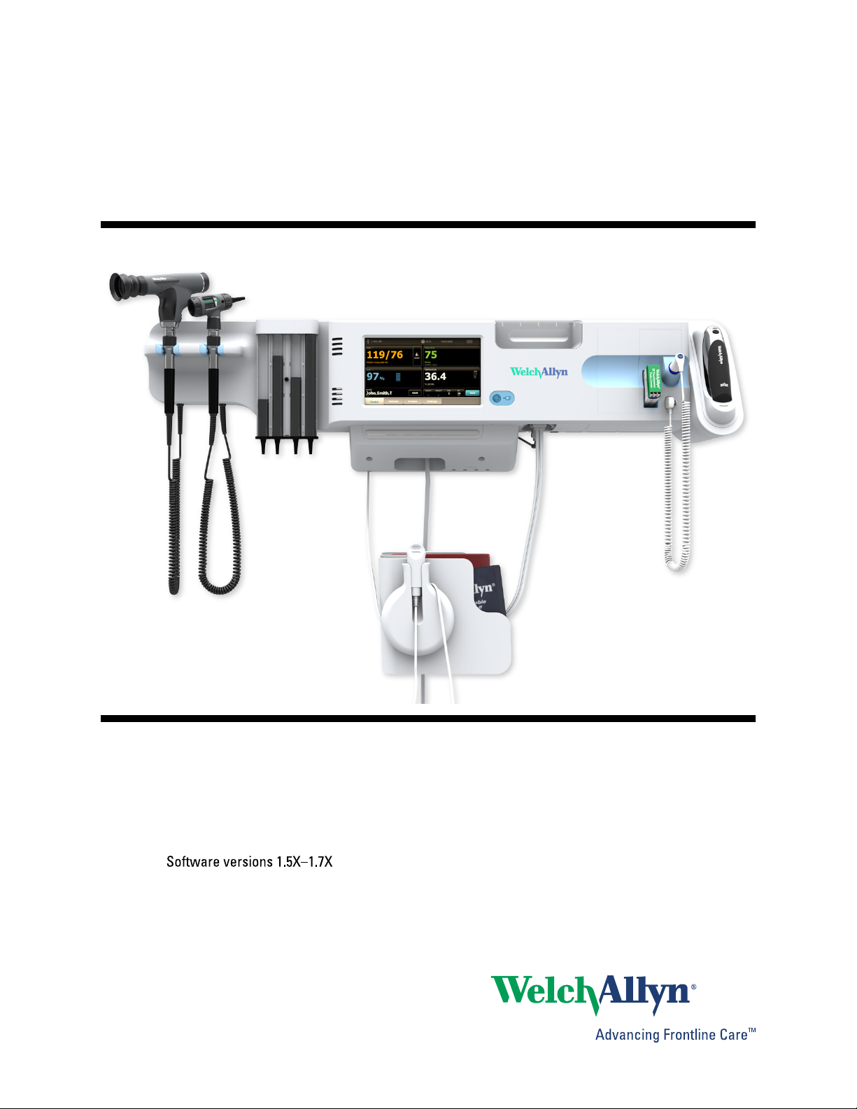
The Welch Allyn Connex® Integrated Wall System combines the advanced, easy-to-use monitor
capabilities of the Welch Allyn Connex® Vital Signs Monitor 6000 Series with the Welch Allyn 767
Power Handles. This manual (directions for use) is designed to help you understand the
capabilities and operation of the wall system. The information in this manual, including the
illustrations, is based on a wall system configured with non-invasive blood pressure (NIBP), body
temperature, pulse oximetry (SpO2), total hemoglobin concentration (SpHb), pulse rate, weight
scale, and two power handles. If your wall system configuration lacks any of these options, some
information in this manual may not apply.
1
Before using the wall system, read the sections of the manual that pertain to your use of the
system.
Note Throughout this directions for use, the Integrated Wall System may be referred to
as a wall system or monitor.
Note Some product features described in this publication might not be available in your
country. For the latest information about products and features, please call Welch
Allyn Customer Care.
Intended use
Handle module assembly
Handles supply power to Welch Allyn 3.5V instruments.
Connex® Vital Signs Monitor patient monitor
The VSM 6000 Series of monitors is intended to be used by clinicians and medically qualified
personnel for monitoring of neonatal, pediatric, and adult patients for
noninvasive blood pressure,
•
• pulse rate,
• noninvasive functional oxygen saturation of arteriolar hemoglobin (SpO2), and
• body temperature in normal and axillary modes
The most likely locations for patients to be monitored are general medical and surgical floors,
general hospital, and alternate care environments.
The optional Masimo Rainbow SET® and accessories are indicated for the continuous noninvasive
monitoring of total hemoglobin concentration of adult, pediatric, and neonatal patients during both
Page 8

Introduction Welch Allyn Connex® Integrated Wall System
2
motion and no motion conditions, and for patients who are well or poorly perfused in hospitals and
hospital-type facilities.
Optional compatible weight scales (e.g., Health o meter®) can be used for height, weight, and BMI
input.
This product is available for sale only upon the order of a physician or licensed health care
professional.
Contraindications
This system is not intended to be used:
on patients connected to heart/lung machines
•
• on patients being transported outside a healthcare facility
• near an MRI machine
• in a hyperbaric chamber
• near flammable anesthetics
• near electro-cauterization devices
For contraindications of SpO2 and SpHb sensors, consult the sensor manufacturer's directions for
use.
Page 9
Symbols
Documentation symbols
WARNING The warning statements in this manual identify conditions or practices
that could lead to illness, injury, or death.
3
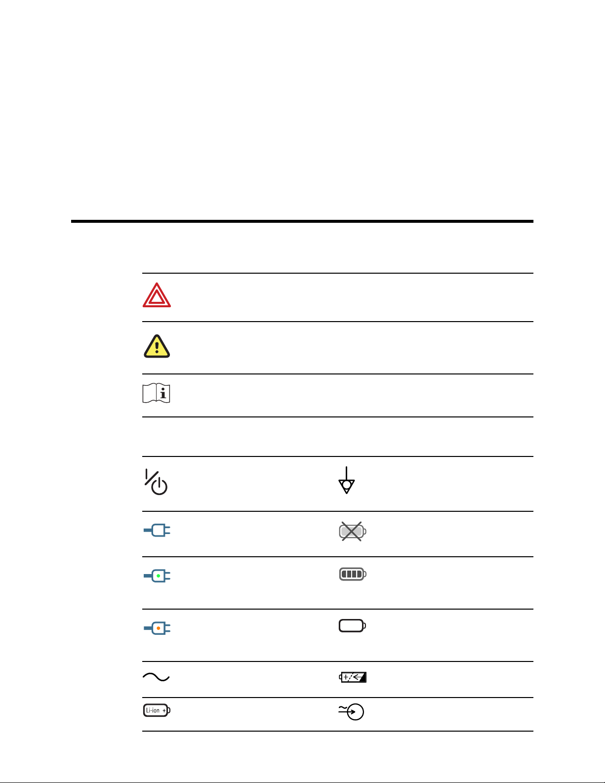
Power symbols
Caution The caution statements in this manual identify conditions or practices that
could result in damage to the equipment or other property, or loss of data. This
definition applies to both yellow and black and white symbols.
Consult operating instructions.
Power on/standby Equipotential terminal
(on the display) monitor is
plugged into Alternating
Current power
(on the monitor, green
indicator) Alternating Current
power present, battery fully
charged
Battery absent or faulty
Battery charge level
(on the monitor, amber
indicator) Alternating Current
power present, battery is
charging
Alternating Current (AC) Rechargeable battery
Li-ion battery AC input power
Battery cover
Page 10
4 Symbols Welch Allyn Connex® Integrated Wall System
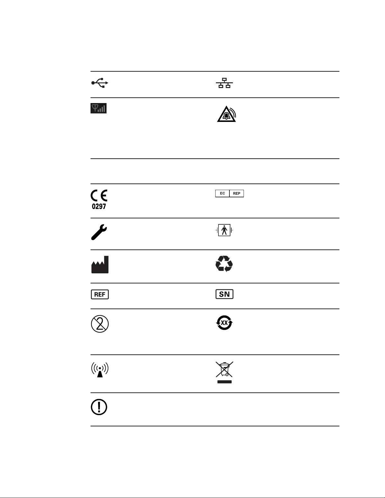
Connectivity symbols
USB Ethernet RJ-45
Wireless signal strength
• Best (4 bars)
• Good (3 bars)
• Fair (2 bars)
• Weak (1 bar)
• No signal (no bars)
• No connection (blank)
Miscellaneous symbols
Meets essential requirements
of European Medical Device
Directive 93/42/EEC
Call for maintenance Defibrillation-proof Type BF
Manufacturer Recycle
Nurse call
Authorized Representative in
the European Community
applied parts
Reorder number Serial number
Do not reuse China RoHS markings for
control of pollution caused by
electronic information
products. XX indicates
Environmentally Friendly Use
Period in years.
Nonionizing electromagnetic
radiation
Restrictions for use of
wireless device in Europe.
European Community's Class
2 radio equipment.
Recycle the product separate
from other disposables
Page 11
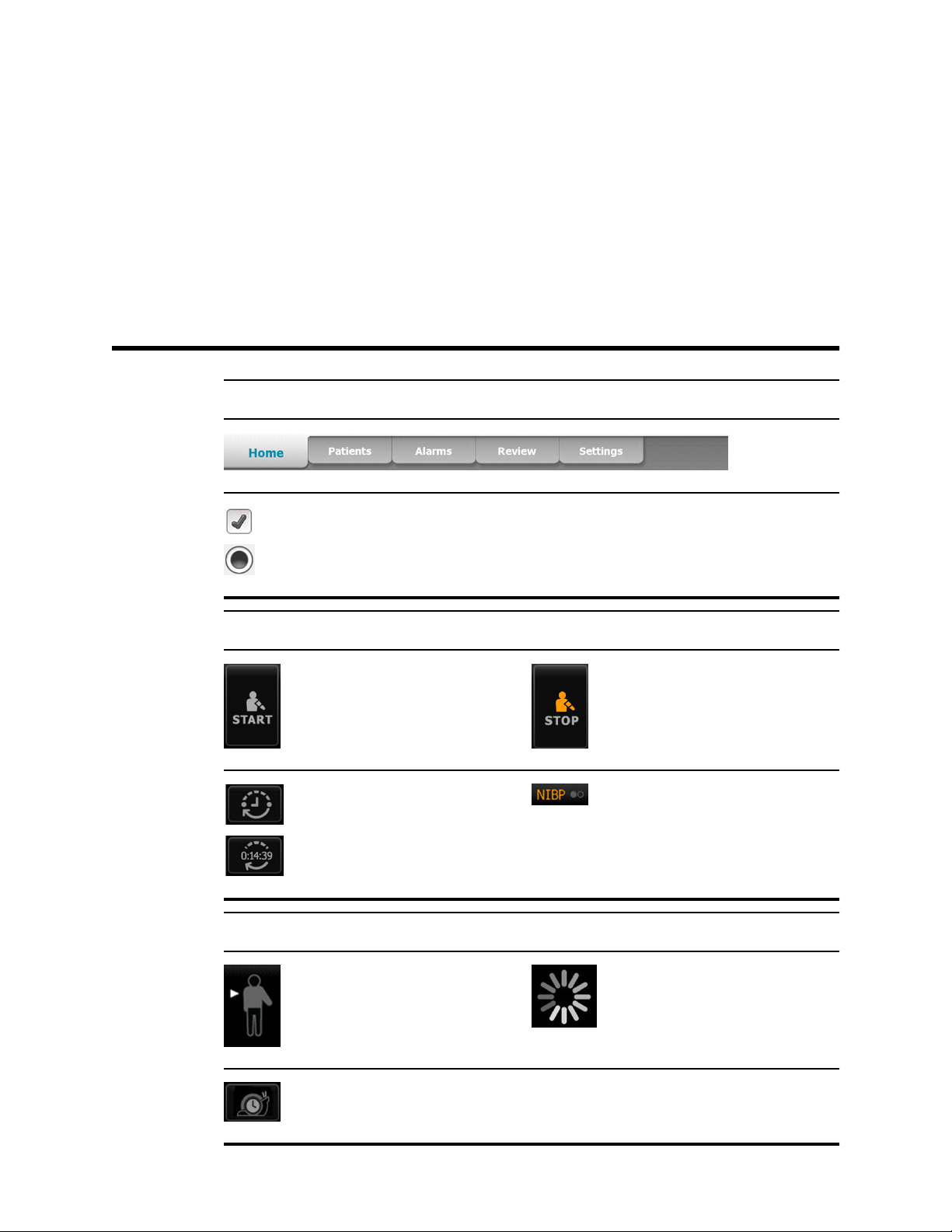
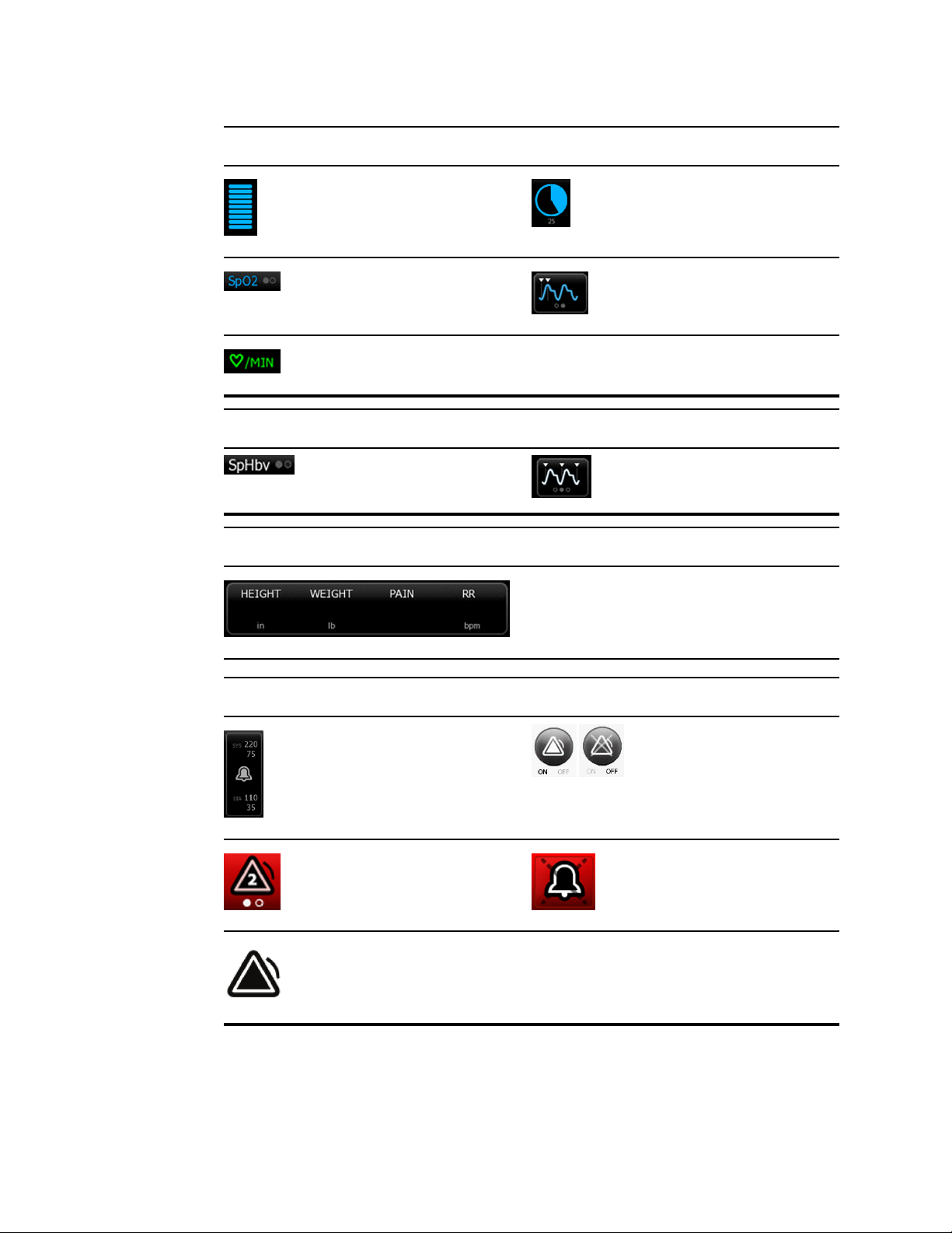
Screen elements
Global navigation
5
Select option
NIBP
Temperature
NIBP start NIBP stop
Intervals status indicators NIBP view toggle
Temperature site control Process indicator
Direct mode selector
Page 12
6 Screen elements Welch Allyn Connex® Integrated Wall System
SpO2 and Pulse rate
Pulse amplitude bar SatSeconds timer (Nellcor
feature only)
SpO2 view toggle Response mode selector
(touch for Fast mode)
Heart rate (in beats per
minute)
Total hemoglobin (SpHb)
SpHb view toggle Averaging selector
Manual parameters
Alarm and information messages
Alarm limit button
Multiple alarms toggle Alarm audio paused
Alarm active
Manual parameter
selector
Alarm On/Off toggle
Page 13
Directions for use Screen elements 7
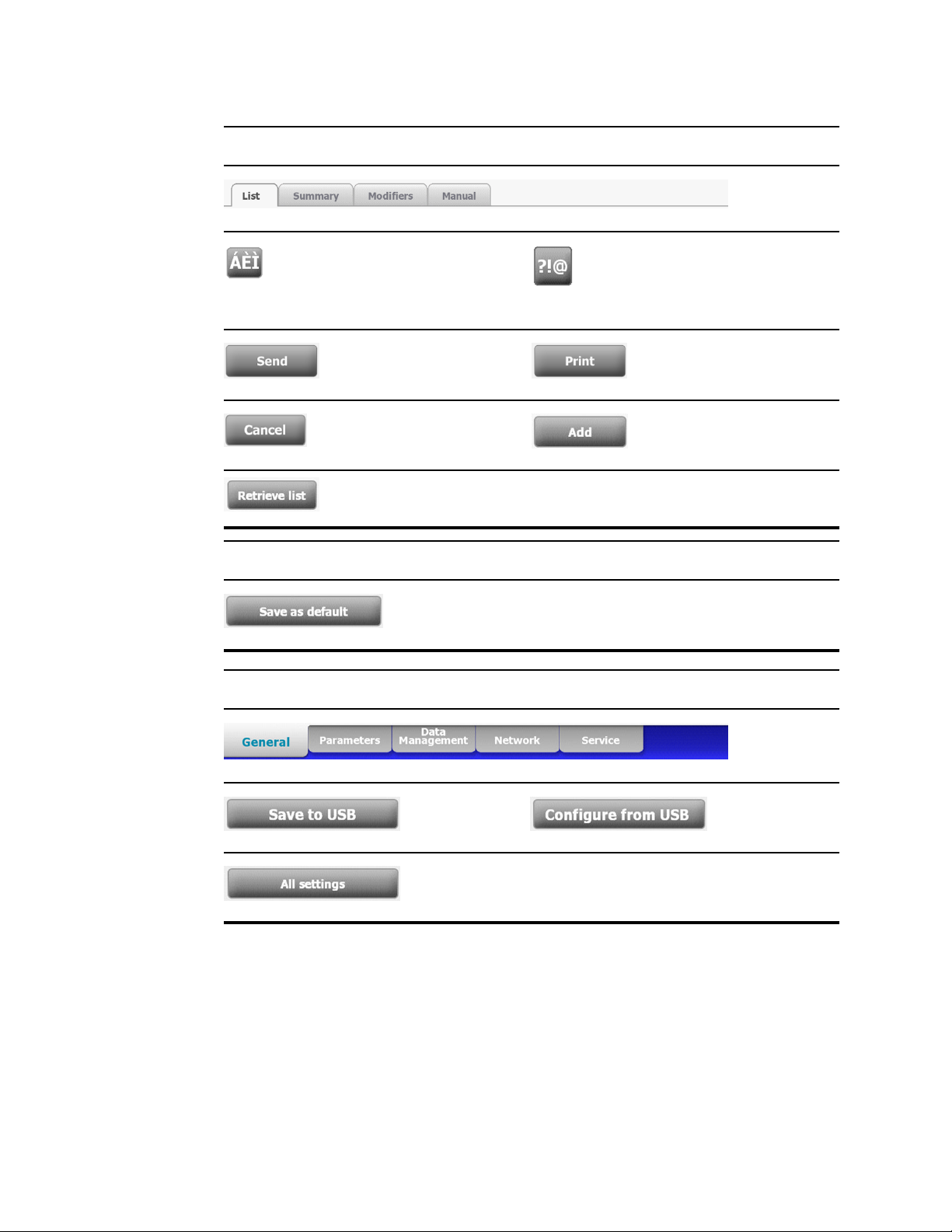
Patients list and review
Settings
Advanced settings
Diacritical marks key
(available for languages
that use diacritical marks;
appearance differs based
on language)
Send patient test reports Print patient test reports
Cancel print request
(Not available)
Retrieve the patient list
from the network
Symbols key
Add patient identifiers
Save configuration
settings
Save to USB flash
drive
Restore factory
default settings
Configure from USB
flash drive
Page 14

8 Screen elements Welch Allyn Connex® Integrated Wall System
Page 15

About warnings and cautions
Warning and caution statements can appear on the monitor, on the packaging, on the shipping
container, or in this document.
The monitor is safe for patients and clinicians when used in accordance with the instructions and
the warning and caution statements presented in this manual.
Before using the monitor, familiarize yourself with the sections of this directions for use that
pertain to your use of the monitor.
Failure to understand and observe any warning statement in this manual could lead to patient
•
injury, illness, or death.
• Failure to understand and observe any caution statement in this manual could lead to damage
to the equipment or other property, or loss of patient data.
9
General warnings and cautions
WARNING Many environmental variables, including patient physiology and
clinical application, can affect the accuracy and performance of the monitor. The
clinician must verify all vital signs information before treating the patient. If there is
any question about the accuracy of a measurement, verify the measurement using
another clinically accepted method.
WARNING Alarm limits are patient- or facility-specific. The clinician must set or
verify alarm limits appropriate for each patient. Each time the monitor is powered
on, you must check that the alarm settings are appropriate for your patient before
you start monitoring.
WARNING Use only Welch Allyn approved accessories, and use them according
to the manufacturer’s directions for use. Using unapproved accessories with the
monitor can affect patient and operator safety and can compromise product
performance and accuracy.
WARNING Inaccurate measurement risk. Do not connect more than one patient
to a monitor.
WARNING Inaccurate measurement risk. Dust and particle ingress can affect the
accuracy of blood pressure measurements. Use the monitor in clean environments
to ensure measurement accuracy. If you notice dust or lint build-up on the monitor's
vent openings, have the monitor inspected and cleaned by a qualified service
technician.
Page 16

10 About warnings and cautions Welch Allyn Connex® Integrated Wall System
WARNING Liquids can damage electronics inside the Connex IWS. Prevent
liquids from spilling on the wall system.
If liquids are spilled on the wall system:
1. Power down the wall system.
2. Disconnect the power plug.
3. Remove the wall system from the wall.
4. Remove battery pack from the wall system.
5. Dry off excess liquid from the wall system.
Note If liquids possibly entered the wall system, remove the wall system
from use until it has been properly dried, inspected, and tested by
qualified service personnel.
6. Reinstall battery pack.
7. Mount the wall system on the wall.
8. Power on the wall system and verify that it functions normally before using it.
WARNING Safety risk. Damaged cords, cables, and accessories can affect
patient and operator safety. Routinely inspect the AC power cord, blood pressure
cuff, SpO2 cable, and other accessories for strain relief wear, fraying, or other
damage. Replace as necessary.
WARNING Fire and explosion hazard. Do not operate the monitor in the presence
of a flammable anesthetic mixture with air, oxygen, or nitrous oxide; in oxygenenriched environments; or in any other potentially explosive environment.
WARNING Fire and shock hazard. Only connect LAN cables contained within the
perimeter of a single building. Conductive LAN cables spanning multiple buildings
may introduce fire or shock hazards unless they are fitted with fiber optic cables,
lightning arrestors, or other applicable safety features.
WARNING The monitor may not function properly if dropped or damaged. Protect
it from severe impact and shock. Do not use the monitor if you notice any signs of
damage. Qualified service personnel must check any monitor that is dropped or
damaged for proper operation before putting the monitor back into use.
WARNING Defective batteries can damage the monitor. If the battery shows any
signs of damage or cracking, it must be replaced immediately and only with a
battery approved by Welch Allyn.
WARNING Improper disposal of batteries may create an explosion or
contamination hazard. Never dispose of batteries in refuse containers. Always
recycle batteries according to local regulations.
WARNING Electric shock hazard. Do not open the monitor or attempt repairs. The
monitor has no user-serviceable internal parts. Only perform routine cleaning and
maintenance procedures specifically described in this manual. Inspection and
servicing of internal parts shall only be performed by qualified service personnel.
WARNING Inaccurate measurement risk. Do not expose to temperatures higher
than 122º F (50º C).
WARNING Inaccurate measurement risk. Do not use the monitor on patients who
are on heart-lung machines.
WARNING Use the monitor only as described in this directions for use. Do not
use the monitor on patients as described in the Contraindications.
Page 17

Directions for use About warnings and cautions 11
WARNING Inaccurate measurement risk. Do not use the monitor on patients who
are experiencing convulsions or tremors.
WARNING Do not place the monitor in any position that might cause it to fall on
the patient.
WARNING Welch Allyn is not responsible for the integrity of a facility's power. If
the integrity of a facility's power or protective earth conductor is in doubt, always
operate the monitor on battery power alone when it is attached to a patient.
WARNING For operator and patient safety, peripheral equipment and
accessories that can come in direct patient contact must comply with all applicable
safety, EMC, and regulatory requirements.
WARNING All signal input and output (I/O) connectors are intended for
connection of only devices complying with IEC 60601-1, or other IEC standards (for
example, IEC 60950), as applicable to the monitor. Connecting additional devices to
the monitor may increase chassis or patient leakage currents. To maintain operator
and patient safety, consider the requirements of IEC 60601-1-1. Measure the
leakage currents to confirm that no electric shock hazard exists.
WARNING Equipment failure and patient harm risk. Do not cover the air intake
vents on the right or exhaust vents on the front of the Connex IWS. Covering these
vents could cause overheating or muffling of alarms.
WARNING This equipment is not suitable for use in the presence of electrosurgery.
WARNING Cross-contamination or nosocomial infection risk. Clean and disinfect
the monitor on a routine basis according to your facility's protocols and standards
or local regulations. Thorough hand-washing before and after contact with patients
greatly reduces the risk of cross-contamination and nosocomial infection.
WARNING The physical assessment instruments (handles) are designed for
intermittent use. On-time should not exceed 2 minutes. Allow at least 10 minutes offtime between patients.
CAUTION United States Federal law restricts this monitor to sale, distribution, or
use by or on the order of a physician or licensed healthcare professional.
CAUTION Welch Allyn is not responsible for the integrity of any wall mounting
interface. Welch Allyn recommends that you contact your Biomedical Engineering
Department or maintenance service to ensure professional installation, safety, and
reliability of any mounting accessory.
CAUTION Electromagnetic interference risk. The monitor complies with
applicable domestic and international standards for electromagnetic interference.
These standards are intended to minimize medical equipment electromagnetic
interference. Although this monitor is not expected to present problems to other
compliant equipment or be affected by other compliant devices, interference issues
still may occur. As a precaution, avoid using the monitor in close proximity to other
equipment. In the event that equipment interference is observed, relocate the
equipment as necessary or consult manufacturer's directions for use.
CAUTION Use only a Class I (grounded) AC power supply cord for powering this
monitor.
Page 18

12 About warnings and cautions Welch Allyn Connex® Integrated Wall System
CAUTION Do not use a long press of to power down the monitor when it is
functioning normally. You will lose patient data and configuration settings.
CAUTION Never pull on the power cord when removing it from the power outlet.
When disconnecting the power cord, always grasp the attachment plug and not the
cord. Keep the cord away from liquids, heat, and sharp edges. Replace the power
cord if the strain relief or cord insulation is damaged or begins to separate from the
attachment plug.
CAUTION Use only the Welch Allyn USB client cable to connect a laptop
computer to the USB client port. Any laptop connected to the monitor must be
running on a battery, a 60601-1 compliant power supply, or a 60601-1 compliant
isolation transformer.
CAUTION If the touchscreen is not responding properly, refer to the
troubleshooting section. If the problem cannot be resolved, discontinue use of the
monitor and contact an authorized Welch Allyn service center or qualified service
personnel.
CAUTION Verify patient identity on the monitor after manual or barcode entry and
before printing or transferring patient records.
Page 19

Controls, indicators, and connectors
Note Your model might not contain all of these features.
Front view
13
No. Feature Description
1 Physical assessment instruments -
Handles and handle cradles
2 Rheostat Located on each handle. Turn clockwise to increase light
3 Exhaust vents Exhaust vents cool the monitor.
4 LCD screen 1024 x 600 color touchscreen provides a graphical user
5 Storage compartment Provides covered storage for additional probe covers and
6 Expansion slots Provide space to add modules.
7 SureTemp® Plus thermometer probe
covers
8 SureTemp® Plus thermometer probe Supports temperature measurements from oral, axillary,
Handles will accept any 3.5V Welch Allyn instrument head.
The handle cradles support using one handle at a time. A
handle turns on automatically when you remove it from a
cradle and turns off when you return it.
output; turn counterclockwise to decrease light output.
interface.
other small accessories.
Support temperature measurements from oral, axillary, and
rectal sites.
and rectal sites.
Page 20
14 Controls, indicators, and connectors Welch Allyn Connex® Integrated Wall System
No. Feature Description
9 Braun ThermoScan® PRO 4000
thermometer and dock
10 SureTemp® Plus thermometer
connector
11 Blood pressure and pulse oximetry See front underside view for more detail.
12 Power switch and LED Power-on/Standby switch.
13 USB/Comms cover Houses light bar.
14 Light bar Provides a visual alarm with red and amber LEDs.
15 Speaker Provides tones. A piezo beeper inside the monitor provides
16 Specula dispenser Dispenses KleenSpec® disposable specula in pediatric
Support temperature measurements from the ear. Dock
charges the thermometer battery.
Secures the probe connection to the wall system.
The LED indicates the charging status when connected to
AC power:
• Green: The battery is charged.
• Amber: The battery is charging.
Provides access to host USB connections for optional
accessories and some routing for cords and cables.
backup.
(2.75 mm) and adult (4.25 mm) sizes.
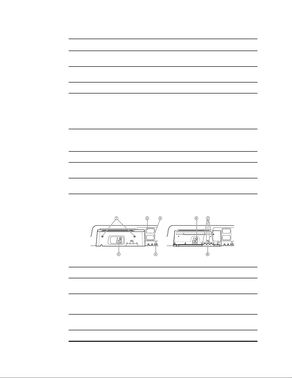
Front underside views
(Left: USB/Comms cover attached; Right: USB/Comms cover removed)
1 Retention screws Supports removing and attaching USB/Comms cover.
2 Blood pressure Self-contained module for easy replacement. Supports
dual-lumen or single-lumen hoses.
3 Pulse oximetry Optional Nellcor (SpO2) or Masimo Rainbow SET (SpO2 or
combined SpO2/SpHb) in a self-contained module for easy
replacement.
4 USB-to-computer connector Provides a connection to an external computer for testing,
data transfer, and software upgrades.
5 Power connection Provides an external AC power connection.
Page 21
Directions for use Controls, indicators, and connectors 15
No. Feature Description
6 Ground lug (equipotential terminal) Supports electrical safety testing; terminal for connecting a
potential equalization conductor.
7 USB connectors Provides access to host USB connections for optional
accessories.
8 USB cable retainer Reduces strain on USB cables and connectors; helps
prevent cables from disconnecting.
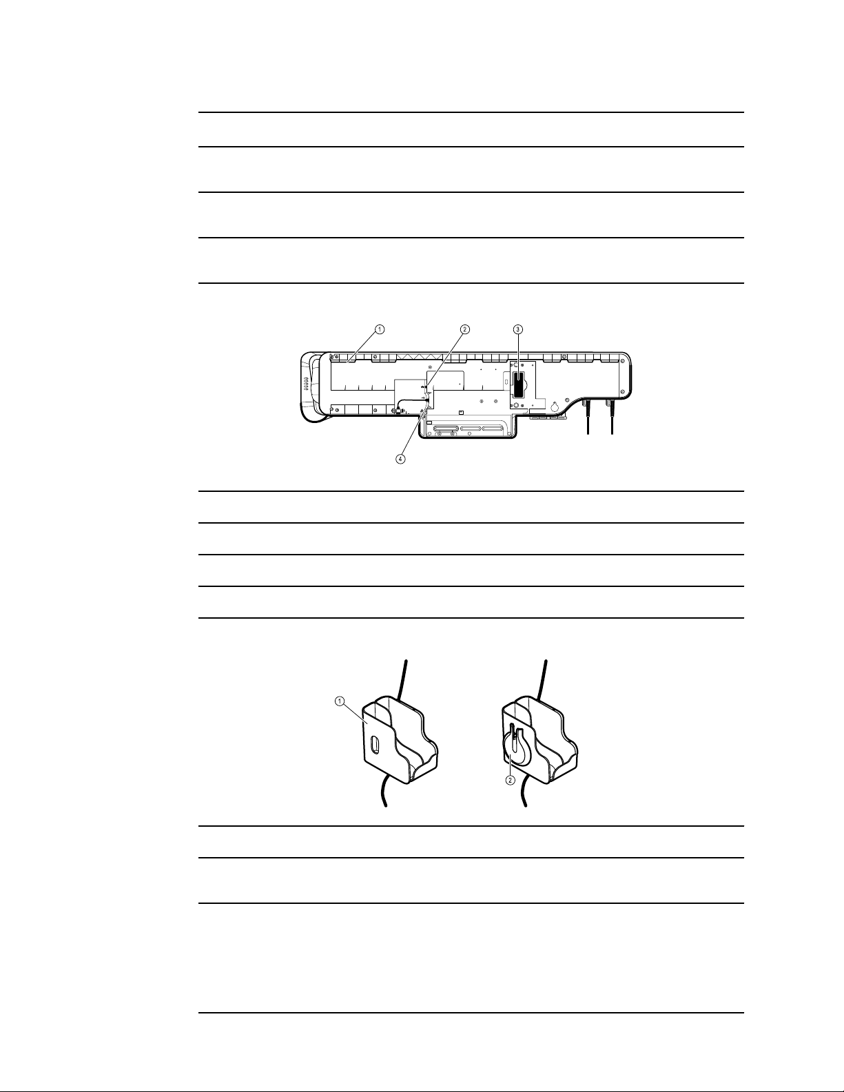
Back view
1 Recess for mounting bracket Secures the monitor when mounted on the wall.
2 Ethernet RJ-45 Provides a hardwired connection to the computer network.
3 Li-ion battery Provides backup power to wall system.
4 Nurse call Provides a connection to the hospital nurse call system.
Accessory bin
1 Accessory bin Stores accessories and organizes cables.
2 SpO2 holder Provides location to wrap SpO2 cable and attach SpO2
finger clip.
Page 22
16 Controls, indicators, and connectors Welch Allyn Connex® Integrated Wall System
No. Feature Description
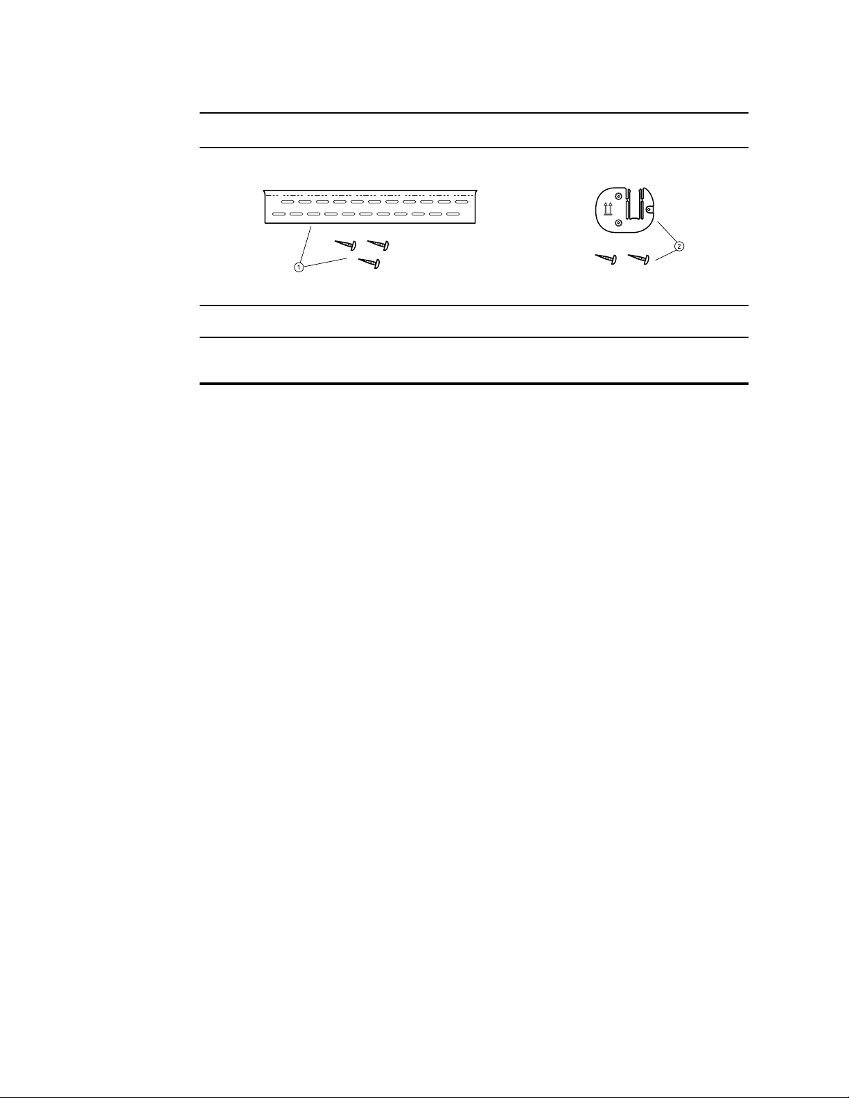
Mounting materials
1 Wall mounting rail bracket and hardware Secures the wall system to the wall.
2 Accessory bin mounting bracket and
hardware
Secures accessory bin to the wall and provides routing and
strain relief for power cord.
Page 23
Setup
CAUTION Welch Allyn is not responsible for the integrity of any wall mounting
interface. Welch Allyn recommends that you contact your Biomedical Engineering
Department or maintenance service to ensure professional installation, safety, and
reliability of any mounting accessory.
Supplies and accessories
17
For a list of all approved supplies and accessories, see Approved Accessories in the Appendix.
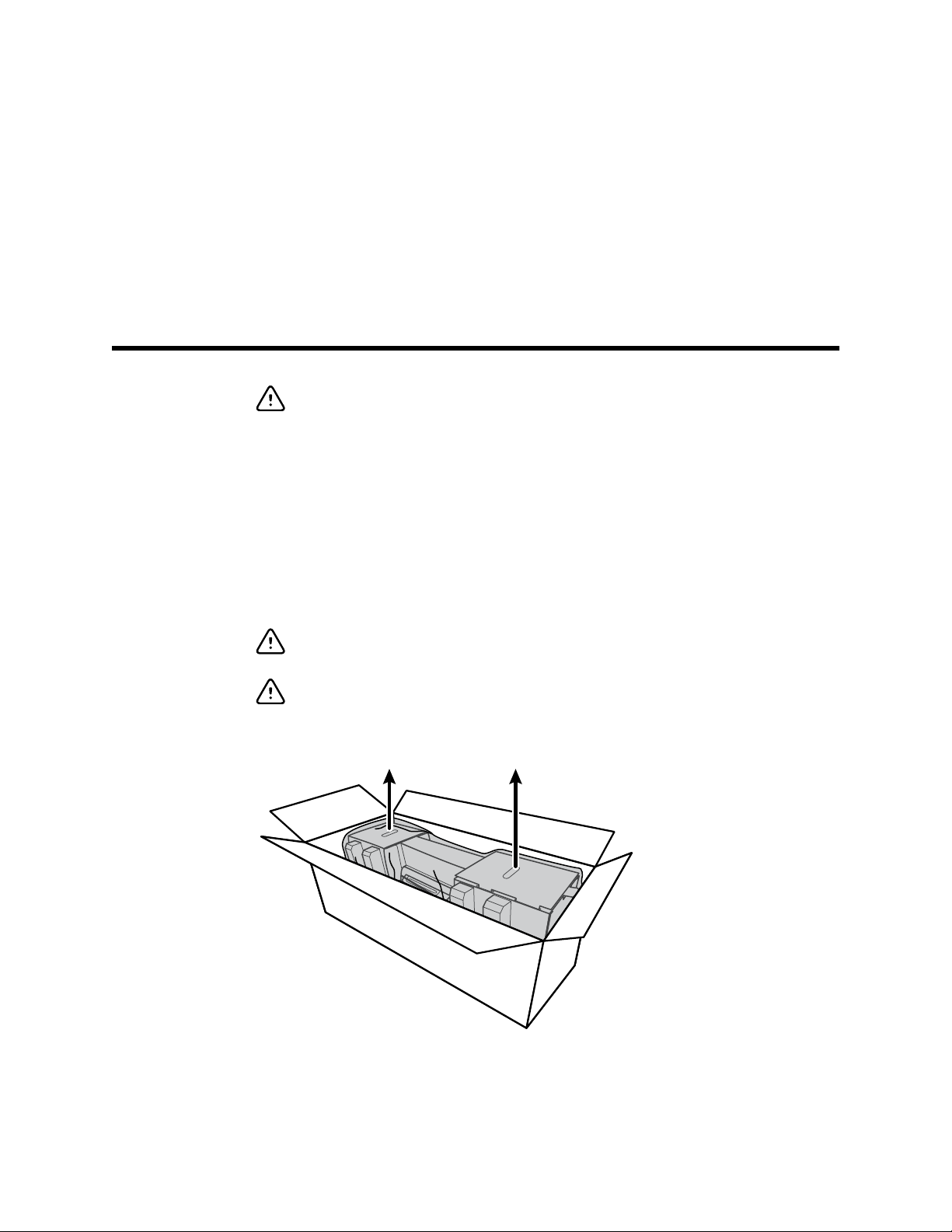
Unpack the wall system
This procedure applies to first-time setup of the wall system.
CAUTION You must follow these instructions exactly to ensure safety and ease of
assembly.
CAUTION Do not remove any packing materials around the wall system until the
instructions tell you to do so.
1. Lift the wall system out of the box by the cardboard handles.
2. With the wall system still in its packing material, place it onto a table or flat work surface and
remove it from the plastic bag.
Page 24
18 Setup Welch Allyn Connex® Integrated Wall System
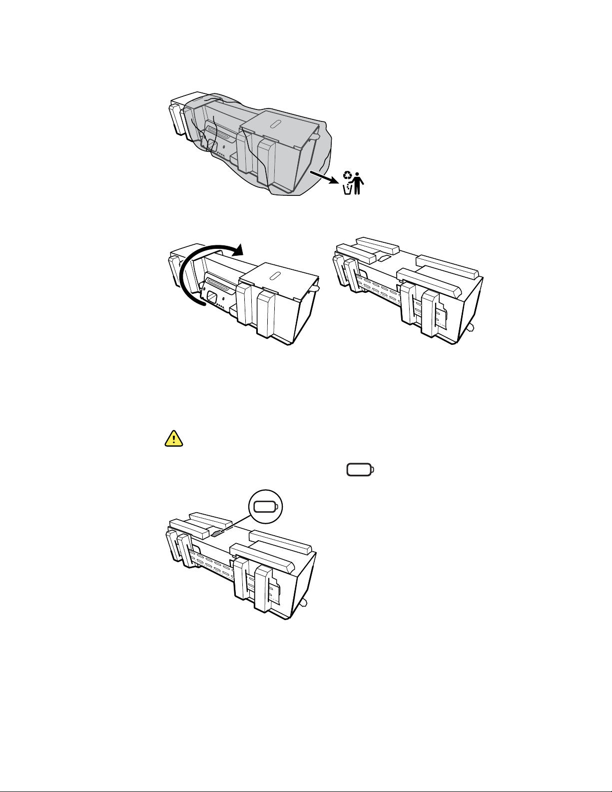
3. Turn the wall system over so that back of the wall system faces up.
Insert the battery
This procedure applies to first-time setup of the wall system. Therefore, the wall system is
assumed to be shut down.
1. Locate the battery compartment, indicated by .
2. Insert the battery. (The battery is in a pink anti-static bag in the accessory box.)
WARNING Risk of fire, explosion, and burns. Do not short-circuit, crush,
incinerate, or disassemble the battery pack.
Page 25

1
2
Directions for use Setup 19
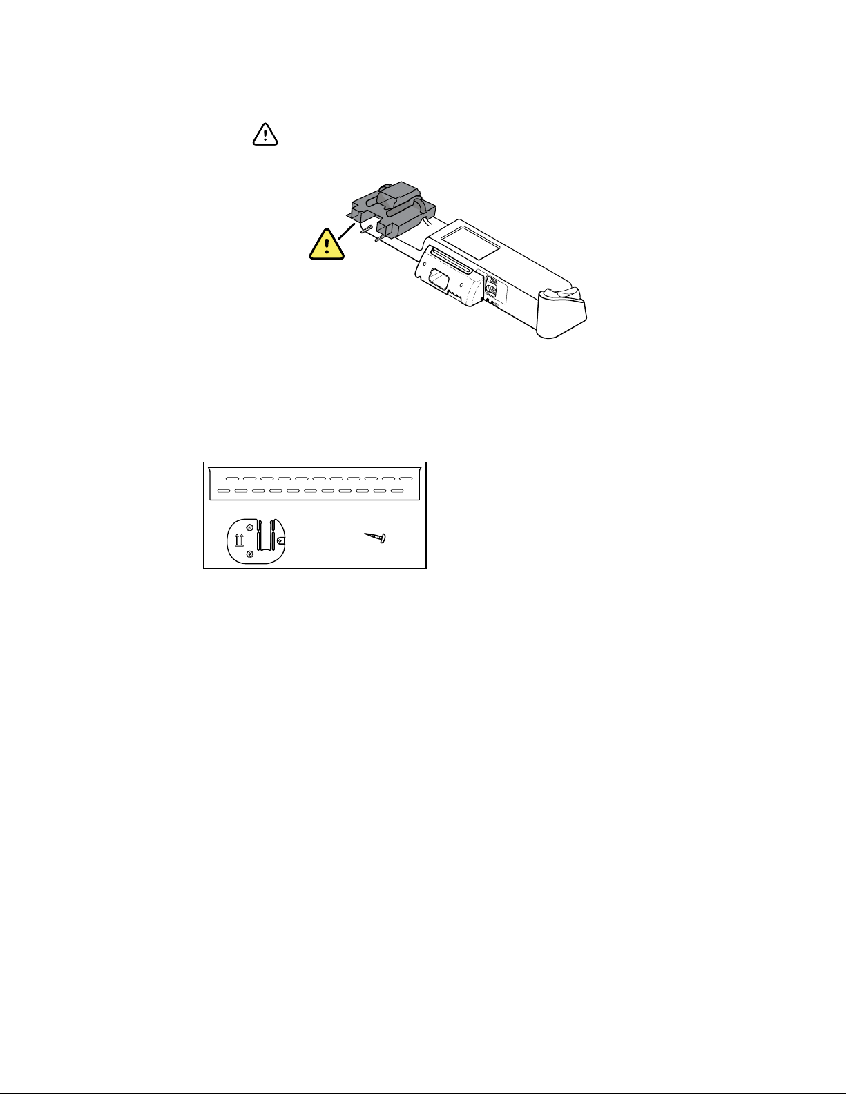
Prepare for mounting
1. Slide the mounting rail bracket out of the packing material and put it aside. Do not discard.
Then flip the wall system onto its back.
2. Remove the cardboard end caps and all foam as shown and put aside for recycling.
Page 26
6 x
20 Setup Welch Allyn Connex® Integrated Wall System
CAUTION Do not remove the cardboard securing the handles on
the left side of the wall system at this time. The cardboard prevents
damage to those instruments during the mounting process.
Mounting hardware inventory
Use these items to mount the wall system.
Tools list
Use these tools to mount the wall system.
#2 Phillips screwdriver
•
• level
• tape measure
• stud finder
• drill
• 1/8-inch (3.17 mm) diameter drill bit
Mounting location
• Mounting rail bracket
• Accessory bin bracket
• Screws
Before mounting the wall system, consider the following recommendations to determine the best
mounting location:
Mount the wall system to studs.
•
• Mount the wall system within reach of the AC power outlet. The power cord is 8 ft. (2.44 m)
long.
• Avoid brightly lit areas.
• Blood pressure tubing is 8 ft. (2.44 m) long.
Page 27
1
2
r
Directions for use Setup 21
• Position the wall system so that all instruments are accessible and in a location that allows for
ergonomic examinations.
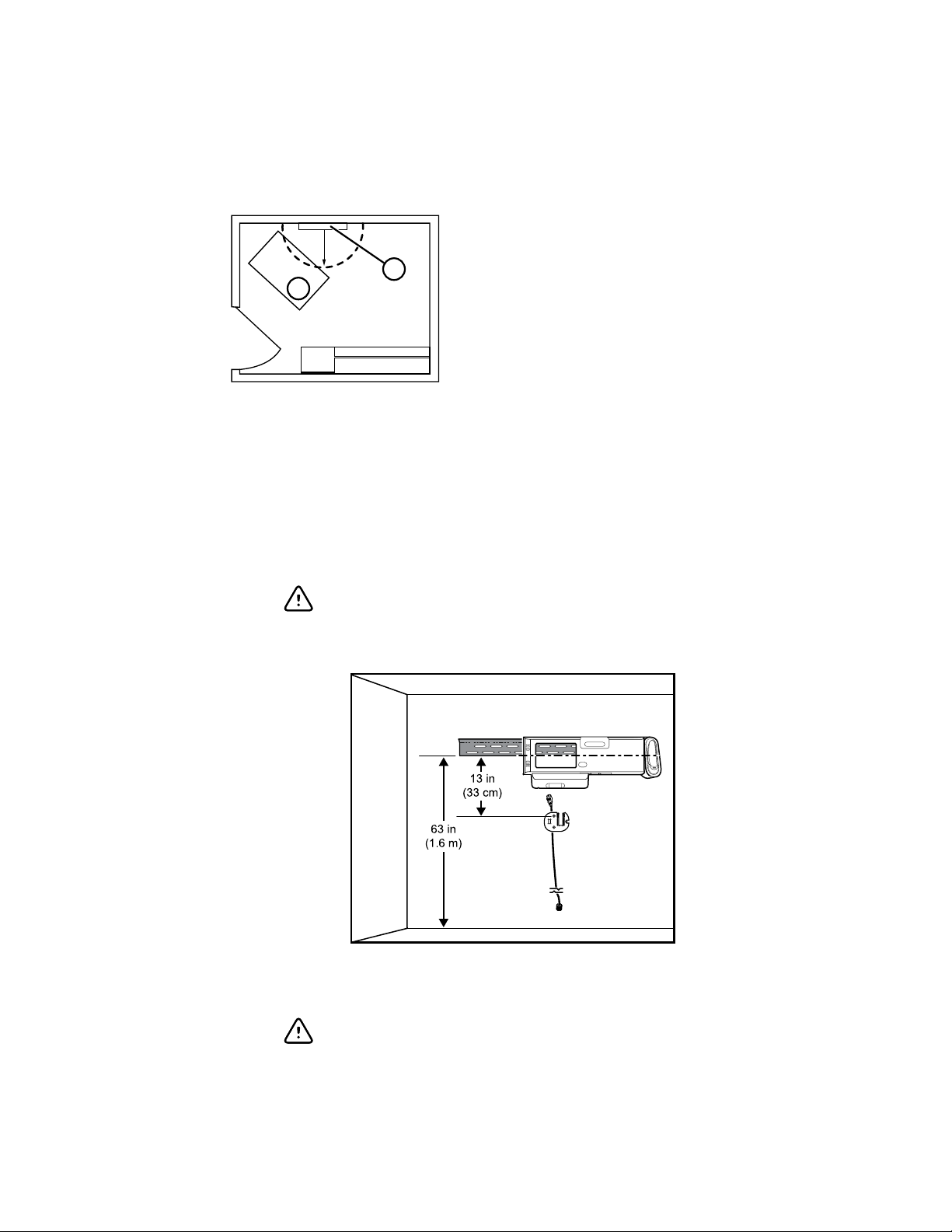
Sample room layout
Connex Integrated Wall System
1.
Examination table
2.
Mount the wall system
1. On the selected wall, find and mark the studs, and choose the system height and
corresponding height for the mounting rail bracket.
Recommendation: Place the mounting rail bracket 63 in. (1.6 m) from the floor, which
places screen center height at approximately 63 in. (1.6 m) from the floor.
CAUTION This drawing shows the physical relationships of the
mounting brackets to each other and to the wall system after you
complete the mounting instructions. Do not place the wall system
on the wall until you have completed all preliminary steps.
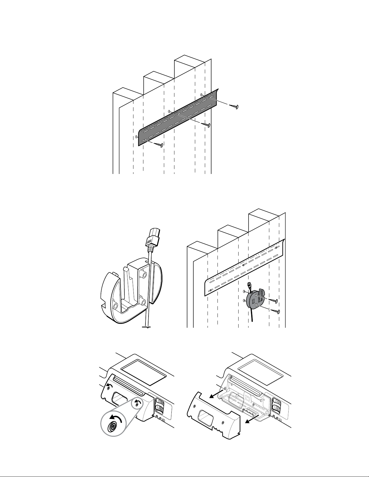
2. Affix the mounting rail bracket to three studs at the selected height using the available screws
(anchors are provided for additional support).
CAUTION Ensure that the upper "lip" of the bracket sticks out
from the wall and that the bracket is level.
Page 28
22 Setup Welch Allyn Connex® Integrated Wall System
3. Route the power cord through the channel in the back of the accessory bin bracket, then
mount the bracket on the center stud at least 13 in. (33 cm) below the mounting rail bracket.
4. Before mounting the wall system, remove the cover by loosening the captive retention screws.
Page 29

Directions for use Setup 23
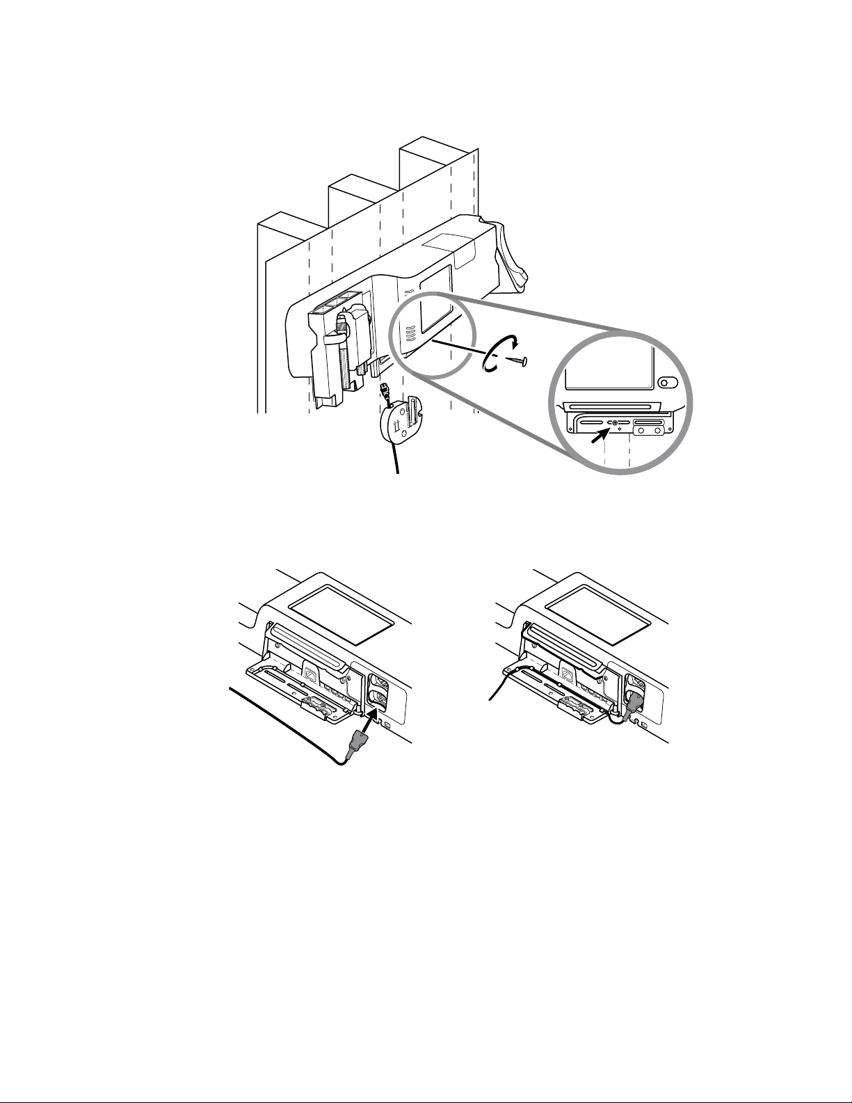
5. Hang wall system on the mounting rail bracket.
WARNING Ensure that the ribs on the back of the wall system
fully engage the mounting rail bracket. The wall system should be
level and flush to the wall.
6. Select one of the three available slots at the bottom of the unit that overlaps a stud, and
secure the unit to the stud with the remaining screw.
WARNING Failure to install this security screw may result in
personal injury and equipment damage.
Page 30
24 Setup Welch Allyn Connex® Integrated Wall System
7. If the wall unit is configured for SpO2 or SpHb, connect the sensor cable and route it through
the channel above the security screw you just installed.
8. Re-attach the cover.
a. Thread the sensor cable through the cutouts on the top right and bottom left of the cover.
Page 31

Directions for use Setup 25
b. Tighten the two retention screws.
9. Attach the system power cord to the wall unit. Do not plug the cord into an outlet at this time.
Mount the accessory bin
1. Mount the accessory bin on the accessory bin bracket, then loosely wrap the excess power
cord around the accessory bin bracket.
2. If your wall system is configured for SpO2 (or SpHb), attach the spool to the accessory bin by
sliding the spool onto the retention clip.
Page 32

26 Setup Welch Allyn Connex® Integrated Wall System
3. Properly orient and insert the sensor cable into the patient cable connector. (You just
connected the opposite end of the sensor cable to the wall system.) Ensure the sensor cable is
inserted completely, then close the protective cover. (See the sensor manufacturer's
directions for use.)
4. Wrap the excess patient cable around the spool, and place the finger clip in the holder.
Connect the blood pressure (NIBP) hose
1. Align the hose connector with the hose connector port on the bottom of the monitor.
2. Insert the hose connector, pressing firmly until it clicks into place.
3. Attach a blood pressure cuff to the tubing (see the cuff manufacturer's directions for use),
then store the cuff in the accessory bin.
Page 33

Directions for use Setup 27
Set up the physical assessment instrument handles and specula dispenser
1. Attach the specula dispenser. Ensure that the keyhole locking slots on the back of the
dispenser engage the locking screws on the wall system, then push down firmly.
2. Remove cardboard securing instrument handles.
3. Attach Welch Allyn 3.5V instrument heads of your choice to the handles. See the directions for
use for each instrument head.
Set up the SureTemp® Plus thermometer
If your wall system is configured for a SureTemp Plus thermometer, follow these setup
instructions.
Align the probe well with the tabs facing up and down and insert the probe well into the
1.
temperature module.
The probe well snaps into place when it is fully seated.
Page 34

28 Setup Welch Allyn Connex® Integrated Wall System
2. Hold the temperature probe cable connector with the spring tab on the right and insert it into
the probe port of the temperature module. Push it into place until it clicks.
3. Insert the temperature probe into the probe well.
4. Open a box of probe covers and place it in the probe cover box holder.
Note Spare boxes of probe covers can be stored in the compartment on
the top of the wall system.
Set up the Braun ThermoScan® PRO 4000 thermometer
If your system is configured for the Braun ThermoScan thermometer, follow these setup
instructions.
Remove the thermometer from the package and discard the protective casing. Then open a
1.
box of probe covers and place it in the dock.
Page 35

20
Probe
Covers
Directions for use Setup 29
2. Remove the thermometer cover, insert the battery, replace the thermometer cover, then place
the thermometer in the dock.
Connect AC power
The wall system uses both battery and AC power. After completing all other setup activities, you
can apply power to the wall system.
Insert the power plug into an outlet to power the monitor and to charge the battery.
1.
Page 36

30 Setup Welch Allyn Connex® Integrated Wall System
Note New batteries are only 30 percent charged. You must plug the wall
system into AC power to fully charge the battery. Do not plug in the
power cord until completing all preliminary steps.
2. Proceed to Startup.
Attach an accessory
1. Shut down the wall system and detach the power cord. Then remove the cover from the wall
system by loosening the captive retention screws.
2. Loosen the two screws on the cable retention clamp and remove it. Then connect the USB
cable(s) to an available connector and thread the cable(s) through the cable guide(s).
3. Replace the cable retention clamp and tighten the two screws.
4. Re-attach the cover.
a. Thread the SpO2 (or SpHb) cable through the cutouts on the top right and bottom left of
the cover.
Page 37

Directions for use Setup 31
b. Tighten the two retention screws.
5. Re-attach the system power cord and power up the wall system.
Note Some accessories require a license to enable them for use. These accessories are
packaged with an authorization code and instructions for activating the license
using the Welch Allyn Service Tool. For more information, refer to the instructions
and the service tool installation guide.
Page 38

32 Setup Welch Allyn Connex® Integrated Wall System
Page 39

Startup
Power
The power button, located on the front of the monitor, performs the following functions:
Powers up the monitor
•
• Sets the monitor into Display power saving mode, except when an alarm condition is active
(brief press)
• Resets the monitor and sets the monitor into Standby mode (press and hold for 6 seconds)
33
CAUTION Do not use a long press of to power down the monitor when it is
functioning normally. You will lose patient data and configuration settings.
The LED in the center of the power plug symbol indicates the battery charging status:
Green indicates that AC power is present and that the battery is fully charged.
•
• Amber indicates that AC power is present and that the battery is charging.
The monitor has distinct power states.
Monitor on
The monitor is operating on battery power or AC power. You can utilize the monitor's features, and
the display is active.
Display power saving
The monitor is operating on battery or AC power, but the display is off to conserve power. A brief
press of the power button sets the monitor into Display power saving mode from the active state.
Settings for this mode can be changed in the Advanced Settings Display tab.
Battery-powered accessories connected to the monitor continue to charge while the monitor is in
this mode and connected to AC power.
Note The monitor will not enter the Display power saving mode while an alarm condition
is active. In addition, the monitor will exit this mode if an alarm occurs.
Page 40

34 Startup Welch Allyn Connex® Integrated Wall System
The following actions will return the monitor display to the active state:
• Touch the screen
• Remove the temperature probe from the probe well
• Attach the SpO2 sensor to a patient
•
Press
Standby
The monitor is plugged into a power outlet, but the sensors and the display do not operate.
Note Because power is still available to charge the battery and power the monitor, the
monitor is in Standby mode.
The monitor remains in Standby mode until you press . Settings for this mode can be changed
in the Advanced Settings Display tab.
Power up the monitor
The monitor runs a brief diagnostic self-test each time it powers up.
WARNING Equipment failure risk. The monitor includes a fan that circulates air
through the device. If the fan does not run when you power up the device, remove it
from use and inform qualified service personnel immediately. Do not use the
monitor until the problem is corrected.
WARNING To ensure patient safety, listen for two audible indicators (a piezo
beeper and a speaker tone) and watch for visual alerts at power-up. Correct any
system errors before using the monitor. In addition to the audible indicators, the
monitor LED light bar illuminates to alert you of alarms. Amber indicates a low-level
alarm. Flashing amber indicates a medium-level alarm. Flashing red indicates a
high-level alarm.
WARNING Always observe the monitor during power-up. If any display fails to
illuminate properly, or if an error code displays, inform qualified service personnel
immediately, or call your nearest Welch Allyn Customer Service or Technical
Support facility. Do not use the monitor until the problem is corrected.
CAUTION Always use the monitor with an adequately charged and properly
functioning battery. For continuous monitoring, always connect to AC power.
CAUTION Use only a Class I (grounded) AC power cord for powering this monitor.
Press to power up the monitor.
Following a successful self-test, the monitor displays the Welch Allyn logo, the LED light bar
(located on the handle) flashes, and a power-up tone sounds. The startup screen then appears
with the following banner across the bottom.
If a system error is detected, the monitor becomes inactive until you press or until the
monitor shuts down automatically. The monitor displays a system fault message that contains
Page 41

Directions for use Startup 35
a wrench icon and a system fault code to aid service personnel and engineers in
diagnosing the problem.
Power down the monitor
1. Touch the Settings tab.
2. Touch the Device tab.
3. Touch Power down.
This power-down method, which places the monitor into Standby mode, ensures that patient
measurements are retained in the monitor memory for a maximum of 24 hours. (These saved
measurements are available for recall, printing, or to send electronically to the network.) This
method also ensures that any configuration settings you have changed and saved will be
maintained at the next startup.
Note Because power is still available to charge the battery and power the monitor, the
monitor is in Standby mode.
Reset the wall system
If the wall system stops functioning, you can press and hold for approximately 6 seconds
to allow the hardware to completely cycle off and to reset the wall system configuration
settings to the last saved default power-up configuration. The button is located on the front of
the wall system.
CAUTION Do not use a long press of to power down the wall
system when it is functioning normally. You will lose patient data
and configuration settings.
Note Because power is still available to charge the battery and power
the wall system, the wall system is in Standby mode.
Page 42

36 Startup Welch Allyn Connex® Integrated Wall System
Select a language
When you power up the wall system for the first time, the language selection screen appears.
1. Select your language.
2. Touch Exit.
The Home tab appears.
Set the date and time
1. Touch the Settings tab.
2. Touch the Device tab.
3. Touch the Date/Time vertical tab.
4. To change the date and time values: Touch the up and down arrow keys or touch and
enter a value.
Repeat for each value you want to change.
Note The date and time stamps on saved patient measurements will
adjust in response to new date and time settings.
Enter clinician information
1. Go to the Clinician tab using one of these methods:
• Touch the Clinician ID section (left edge) of the Device Status area on the Home tab.
• Touch the Settings tab and then touch the Clinician tab.
2. To enter the clinician name, touch , located at the right of the text field, and enter
characters.
You can enter up to 32 characters for the clinician's first and last name. Enter only 1 character
for the middle initial.
3. To enter the clinician ID, use one of these methods:
Page 43

Directions for use Startup 37
• Touch and enter the ID.
• Scan the clinician's barcode with a barcode scanner. The scanned ID appears in the field.
4. If prompted, enter your system password in the Authentication pane.
5. Touch OK to save your entries and return to the Home tab.
Set the default configuration
1. Touch the Settings tab.
2. Touch the Device tab.
3. Enter or adjust the desired settings you want to add or change.
Note The new settings appear as they are completed but are temporary
until they are saved.
4. Touch Save as default.
5. Touch OK to confirm that you want to overwrite your previous settings and replace them with
your current settings in the startup default configuration. Or touch Cancel to retain the
previous settings.
The new settings are stored as the default startup settings once you restart the monitor.
Note If your monitor is connected to the network, the date and time settings are
synchronized with the network settings.
Note The date and time stamps on saved patient measurements will adjust in response to
new date and time settings.
Page 44

38 Startup Welch Allyn Connex® Integrated Wall System
Page 45

Navigation
The monitor screen provides the interface that you use to complete your workflow. You access the
monitor's features by touching the screen.
Home tab
The Home tab includes the following areas:
39
Item Area
1 Device Status
2 Content
3 Navigation
Device Status area
The Device Status area, located at the top of the Home screen, displays the following monitor
information, from left to right:
Clinician identification. The format can be a name, ID number, or icon. Touch this area to
•
navigate to the Clinician login.
Page 46

Navigation Welch Allyn Connex® Integrated Wall System
40
• Device location.
• Time and date. Touch this area to navigate to date and time settings.
• Connection status (wired or wireless). The icons indicate which connection type, if any, is
currently active.
Icon Connection type
Ethernet
USB
Wireless
Blank No connection
• Process indicator. This indicator appears when system or patient data is transferred between
the monitor and the network.
• Battery condition. Estimated battery capacity is displayed in hour(s):minute(s) format.
This area also provides:
•
• Shortcuts to some setting controls. For example, touching the Alarm icon displays the Alarms
Battery status
The battery status indicator displays the state of the battery.
The battery status is represented by icons in the right corner of the Device Status area:
•
• The monitor is not connected to a power outlet and is running on battery power. The estimated
• The monitor is connected to a power outlet but the battery does not maintain a charge (or has
Interactive alarm and information messages.
tab.
The monitor is connected to a power outlet and the battery is charging or is fully charged. The
estimated charge rate is displayed as a percentage of capacity.
charge time remaining is displayed in the hour(s):minute(s) format. Each section of the battery
status indicator represents a percentage of remaining charge.
been removed).
When the battery is not being recharged and power becomes low, an information message
displays in the Device Status area.
Page 47

Directions for use Navigation 41
Note Observe the remaining battery charge in the battery status indicator and plug the
monitor into a power outlet as soon as you are able.
If the information message is dismissed or you do not take any action to charge the battery, a low
battery alarm condition results. An error message displays in the Device Status area to prompt you
to take action to help prevent the monitor from shutting down due to a critically low battery.
Alarm and information messages
The Device Status area provides alarm and information messages that are either temporary or
exist as long as the condition to which the message applies remains. Alarm or information
messages may also include controls and/or behavior that you can use to manage alarm and
information messages.
When the monitor detects an alarm condition, an alarm message appears. When multiple alarms
occur, the highest priority message appears. You can cycle through each alarm message by
touching the multiple alarm toggle.
Information messages instruct you to interact with the monitor in a specific way or provide
information that does not require action. You can dismiss an information message by selecting the
control associated with the message or waiting for the message to time out.
Content area
The Content area displays vital sign measurements. It also provides shortcuts to several controls.
The Content area includes the following frames:
NIBP
•
• SpO2 with optional SpHb
• Pulse rate
• Temperature
• Patient
• Manual parameters (height, weight, pain, temperature, respiration, and BMI, depending on
configuration)
Page 48

42 Navigation Welch Allyn Connex® Integrated Wall System
The Content area also includes a Save button, which you use to manually save current
measurements.
Save patient data
Patient data can be saved to the monitor.
After taking a patient reading, touch Save.
A message will appear indicating a successful or failed save.
Note You can configure some profiles and settings to automatically save
measurements.
Navigation area
The Navigation area includes the following tabs:
Home: Displays vital-sign measurements and provides shortcuts to several controls.
•
• Patients: Accesses the patient list, patient summary, patient modifiers, and manual
parameters.
• Alarms: Accesses global alarm response and settings controls, plus alarm limits settings
(available only in Monitor mode).
• Review: Prints, deletes, and sends patient data.
• Settings: Accesses device configuration settings.
To navigate to a tab, touch the tab in the Navigation area with the corresponding name. The active
tab is highlighted.
Display lock
The display lock prevents clinician input, which may be useful when cleaning the display.
Note The lock feature is not a security mechanism.
The display locks when any of the following occur:
You touch Lock display now.
•
• No interaction with the monitor occurs for the period specified in the Display tab. Use the
Advanced tab to set or change the time it takes for the display to lock. (This requires the
Advanced settings access code.)
Lock the display
Follow these steps to touch the screen without activating the controls.
Touch the Settings tab.
1.
2. Touch the Device tab.
3. Touch Lock display now.
The following occurs:
• The Home screen appears.
Page 49

Directions for use Navigation 43
• A title bar with a lock icon ( ) replaces the Navigation area at the bottom of the screen.
• Patient information no longer appears at the bottom left of the screen.
• All controls on the screen are locked, except for on the title bar. If you select any area
Unlock the display
On the locked screen, touch and move Slide to unlock (located at the bottom right) to the
rightmost position on the slidebar.
The following occurs:
• Patient information appears in the Patient frame.
• The Navigation area appears.
• Home tab controls are available for use.
The display also unlocks when any of the following occur:
An alarm condition.
•
• An externally initiated action, such as taking or stopping an NIBP measurement or upgrading
software.
• The monitor powers up.
of the screen other than , a message appears.
Page 50

44 Navigation Welch Allyn Connex® Integrated Wall System
Page 51

Profiles
Profiles are variations of the Home tab. Each profile gives you access to a different set of features.
Choose the profile that best suits your needs.
The monitor offers multiple profiles—including Monitor, Spot Check, and Triage—based on the
model and any upgrade licenses you purchase.
Monitor profile
45
The Monitor profile enables you to use alarms and timed intervals. It is designed for continuous
patient monitoring.
Page 52

Profiles Welch Allyn Connex® Integrated Wall System
46
Spot Check profile
The Spot Check profile is optimized for clinicians who take spot-check vitals readings and do not
need automatic reading or alarm features.
Triage profile
The Triage profile allows for vital signs capture without alarms or access to the Patients tab.
Page 53

Directions for use Profiles 47
Profile feature comparison
The following table compares the features of the profiles.
Feature Monitor Spot Check Triage
Take NIBP, SpO2,
temperature, and pulse
rate readings
Take SpHb readings
(Masimo only)
Configure and use interval
timing setting
Observe and configure
alarm limits
Observe and respond to
physiological alarms
Change patient type
(adult, pediatric, neonate)
View and enter manual
parameters (height,
weight, pain, respiration,
temperature*, BMI**)
Save currently displayed
data to device memory
X X X
X
X
X
X
X X X
X X
X X X
Save and review patient
data
Access Patients tab X X
Access Alarms tab X
Access Review tab X X X
Access Settings tab X X X
* Braun IR thermometers configured to work with the monitor transfer temperature data automatically to the
Temperature frame. You can enter temperature manually if you take a patient temperature with a
thermometer that is not connected to the monitor, and you have selected temperature as one of the four
manual parameters to display.
** Body Mass Index (BMI) is calculated and transferred to the monitor only by an attached weight scale. You
cannot enter or adjust BMI values. BMI displays on the Manual tab and in the Manual parameters frame if
you have selected it as one of the four parameters to display.
X X X
Page 54

48 Profiles Welch Allyn Connex® Integrated Wall System
Select a profile
Follow these steps to select a profile, which controls the appearance and functionality of the
device.
1. Touch Settings.
2. Touch Profiles.
3. Touch the desired profile.
4. Touch Home to return to the Home tab.
Note Profiles cannot be changed while acquiring patient measurements
or while unsaved patient measurements are on the display.
Page 55
Using the keypad, keyboard, and barcode scanner
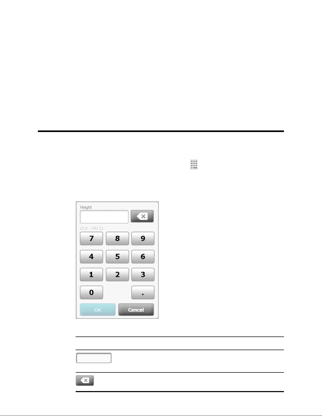
Open the numeric keypad
Touch any field that includes the numeric keypad icon .
49
The numeric keypad appears.
Numeric keypad
The numeric keypad includes the following components:
Component Name Description
Data field Displays the numbers you enter. The field
name appears above and the range of values
you can enter appears below this field.
Backspace key When touched, removes the rightmost
number from the data field.
Page 56

Using the keypad, keyboard, and barcode scanner Welch Allyn Connex® Integrated Wall System
50
Component Name Description
Cancel button When touched, the numeric keypad
disappears and the selected number does not
change.
OK button When touched, the numeric keypad
disappears and the entered number appears
in the associated frame or data field.
Enter a number
1. With the numeric keypad open, touch a number or numbers.
The value must be within the range that appears below the data field.
2. Touch OK.
• If the value is within the required range and format, the numeric keypad disappears and
the entered numbers replace the previous numbers.
• If the number is not within the required range and format, OK remains inactive until you
enter a valid number.
Close the numeric keypad
Touch one of the following:
• OK: Exits the numeric keypad and inserts the number.
• Cancel: Exits the numeric keypad without saving entered numbers.
Open the keyboard
Touch any field that includes the keyboard icon .
The keyboard appears.
Keyboard
The keyboard includes the following components:
Page 57

Directions for use Using the keypad, keyboard, and barcode scanner 51
Component Name Description
Data field Displays the characters you enter.
Backspace key When touched, removes the rightmost
character from the data field.
Space bar When touched, enters a space in the data
field.
Shift key When touched, enters the next letter as
uppercase.
Letters key When touched, returns to the primary
keyboard layout. The keyboard changes
from normal layout when you touch one of
these:
• The symbols key
• The diacritical marks key
Symbols key When touched, the keyboard displays
symbols. The keyboard returns to its
normal layout when you touch one of
these:
• Any symbol
• The letters key
• The symbols key
Note
Diacritical marks key
(appearance varies
in some languages)
When touched, the keyboard displays
letters with diacritical marks. The
keyboard returns to its normal layout when
you touch one of these:
• Any letter
• The letters key
• The diacritical marks key
Note
Next button When touched, accepts the entry for the
current field, then clears the field to allow
data entry for the next field.
The symbols that display
match the selected
language.
This key appears only
when the selected
language uses diacritical
marks.
Cancel button When touched, the keyboard disappears
and the content of the data field remains
the same.
Page 58

52 Using the keypad, keyboard, and barcode scanner Welch Allyn Connex® Integrated Wall System
Component Name Description
OK button When touched, the keyboard disappears
and the entered characters appear in the
data field.
Enter a letter or number
1. With the keyboard open, touch letters or numbers.
2. Do one of the following:
• Touch Next. This control accepts the entry for the current field, then clears the data field
to allow data entry in the next field.
• Touch OK. The keyboard disappears and the entered characters appear in the data field.
Enter a symbol or special character
Note To return to the keyboard's normal layout, touch .
1. With the keyboard open, touch .
Symbols and special characters for the selected language appear.
2. Touch the appropriate symbol or special character.
The keyboard returns to its normal layout.
Enter a diacritical mark
Note Keyboards with diacritical marks are available only for languages that use
diacritical marks.
Note To return to the keyboard's normal layout without saving changes, touch .
Diacritical marks key Language(s)
None (Not applicable) Danish, English, Dutch, German, Italian
French
Page 59

Directions for use Using the keypad, keyboard, and barcode scanner 53
Diacritical marks key Language(s)
Finnish, Norwegian, Spanish, Swedish
Portuguese
Polish
Greek
1. With the keyboard open, touch the diacritical marks key. This key varies based on the
language, as noted above.
The keyboard displays diacritical marks for the selected language and therefore varies from
one language to another. On each diacritical marks keyboard, the letters key in the top left
corner returns you to the standard keyboard.
2. Touch a diacritical mark.
The keyboard returns to its normal layout.
Close the keyboard
Touch one of the following:
• Next: Accepts the entry for the current field, then clears the field to allow data entry for
the next field.
• OK: Exits the keyboard and inserts the data.
• Cancel: Exits the keyboard without saving entered data.
Use a barcode scanner
The monitor enables the scanning of patients’ and clinicians’ barcodes to enter ID information. The
barcode scanner supports linear and two-dimensional barcodes.
If you haven't done so already, attach the barcode scanner to the monitor. Use the instructions to
attach an accessory.
Note Refer to the manufacturer's directions for use to ensure that the scanner is set to
USB Com Emulation mode.
1. Remove the barcode scanner from its holder.
2. Hold the scanner approximately 6 inches (15.4 cm) from the barcode and squeeze the trigger
so that the light from the scanner appears on the barcode.
Once the scanner completes a successful barcode reading, the ID appears in the targeted
area (Patient frame, data field, or Device Status area). See additional notes below.
If the scanner has difficulty reading the barcode, slowly adjust the distance and the angle
between the scanner and the barcode while squeezing the scanner trigger. If it continues to
have difficulty, verify that the barcode is as flat as possible.
Page 60

54 Using the keypad, keyboard, and barcode scanner Welch Allyn Connex® Integrated Wall System
Note You can scan a patient's barcode from the Home tab or the Summary tab. The
scanned ID appears in the Patient frame on the Home tab and in the Patient ID field
on the Summary tab.
Before you scan a barcode on the Summary tab, touch the keyboard icon in the
Patient ID field. To return to the Home tab and begin taking patient measurements,
touch OK.
Note Scanning a clinician ID while the Clinician ID pane is open places the scanned ID
into the Clinician ID section of the Device Status area. Touch OK to return to the
Home tab and to begin taking patient measurements.
Note Use the Advanced settings Data Management tab to change the appearance of the
Clinician ID if you do not want your ID to appear in the Device Status area. (This
requires the Advanced settings access code.) However, this information is still
retained in the monitor memory for recall, printing, or to send measurements
electronically to the network.
Page 61

Patient data management
Patient data is managed through the Patients tab.
From this tab, you can do the following:
Retrieve a patient list from the network or manually create a patient list.
•
• Select a patient from the list.
• Scan a patient ID with the barcode scanner and return an Admit/Discharge/Transfer (ADT)
patient name match.
• Enter additional patient information such as modifiers and manual parameters.
55
CAUTION Verify patient identity on the monitor after manual or barcode entry and
before printing or transferring patient records.
Add a patient to the patient list
Note If the monitor is configured to retrieve the patient list from the network, you cannot
manually add a patient to the patient list.
1. Touch the Patients tab.
2. Touch Add.
3. Touch and then enter patient information. Touch to cycle through the
patient data fields.
Note You can use a barcode scanner to enter a patient ID in the Patient
ID field. Touch in the Patient ID field, scan the barcode,
and touch OK.
4. Touch OK to return to the Home tab.
The information is saved.
CAUTION Verify patient identity on the monitor after manual or barcode entry and
before printing or transferring patient records.
Load patient data with the barcode scanner
You can use a barcode scanner to query existing patient records and perform an ADT patient name
match.
Page 62

56 Patient data management Welch Allyn Connex® Integrated Wall System
Note If the monitor is connected to the network, the monitor can receive a patient name
from patient records associated with a scanned ID number.
1. Ensure that you are on the Home tab.
2. Scan the patient's barcode with the barcode scanner.
The Patient ID appears in the Patient frame.
CAUTION Verify patient identity on the monitor after manual or barcode entry and
before printing or transferring patient records.
Select a patient
1. Touch the Patients tab.
2. If the monitor is connected to the network, touch Retrieve list on the List tab.
The monitor retrieves the patient list from the network.
3. From the patient list, touch the patient's identifier (name, ID number, or location).
The patient's identifier is determined in Advanced settings.
4. Touch Select.
Note In the Spot Check and Triage profiles, previous patient data will be
overwritten by a new save. In the Monitor profile, selecting a new
patient will clear the current patient data and readings.
Patient data can be sorted in ascending or descending order by selecting the heading row and
touching ▲ or ▼.
Manage patient records
Patient records can be sent to the network, printed, or deleted.
Touch the Review tab.
1.
Note Measurements that triggered a physiological alarm are highlighted
on this tab.
2. Select patients by touching the check box next to their names.
3. Touch Send to transmit the records to the network, Print to print the records, or Delete to
permanently remove the records as desired.
Page 63

Directions for use Patient data management 57
CAUTION Verify patient identity on the monitor after manual or
barcode entry and before printing or transferring patient records.
CAUTION Always visually verify the printed patient records.
Note The icon indicates the records have been sent to the
network.
Note You can configure some profiles and settings to automatically send
measurements to the network.
Note Patient measurements older than 24 hours are automatically
deleted from the patient records list on the Review tab.
Note The date and time stamps on saved patient measurements will
adjust in response to new date and time settings.
Delete a patient from the list
Modifiers
1. Touch the Patients tab.
2. From the List tab, touch the patient record you want to delete.
3. Touch Delete.
At the Delete Confirmation window, touch OK to permanently delete the selected patient.
Touch Cancel to cancel the deletion.
Note Deleting a patient from the Patients List does not delete saved
records. Touch Review to see or delete saved records.
Note For monitors connected to the network, deleting a patient on the
monitor does not affect data on the network.
The Modifiers tab enables you to enter additional information for current measurements.
Page 64

58 Patient data management Welch Allyn Connex® Integrated Wall System
Set modifiers
1. Touch the Patients tab.
2. Touch the Modifiers tab.
3. Adjust the NIBP, O2, and Temperature settings as required.
4. Touch OK to accept the changes and return to the home screen, or touch Clear to delete all
entries.
The Modifier settings clear after a power cycle, after you clear the Home tab, or after you
select a new patient.
Page 65

Alarms
59
The monitor presents physiological alarms and technical alarms. Physiological alarms occur when
vital sign measurements fall outside of set alarm limits, but they occur only in the Monitor profile.
Technical alarms occur in all profiles.
Note The three modes of data communication—USB, Ethernet, and IEEE 802.11—are not
intended for real-time alarms.
Alarm types
Type Priority Color Alarm audio tone
• NIBP, SpO2, or SpHb limit exceeded
• Some technical alarms
• Pulse rate limit exceeded
• Some technical alarms
• Temperature limit exceeded
• Some technical alarms
Alarm notification locations
WARNING If you are relying on visual alarm notifications, maintain a clear line of
sight with the monitor and/or Nurse Call. If you are relying on audio alarm
notifications, ensure that you can hear audio alarms from where you are. Set the
volume as needed considering the environment and ambient noise levels.
Nurse Call
High Red 10-pulse tone
Medium Amber 3-pulse tone
Low Amber 2-pulse tone or 1-pulse tone
When the Nurse Call cable is connected and Nurse Call has been enabled, the monitor
immediately notifies the Nurse Call system when an alarm occurs. Nurse Call notification settings
are specified in the Advanced settings.
LED light bar
The light bar on the handle of the monitor illuminates as follows:
Flashing red for high priority alarms
•
• Flashing amber for medium priority alarms
Page 66

Alarms Welch Allyn Connex® Integrated Wall System
60
• Constant amber for low priority alarms
Home tab
Home tab notifications
Notification Description
Device Status area The area changes color and displays a message with an accompanying status
icon or button. If the alarm tone is in a pause interval, a timer countdown appears.
If multiple alarms and information messages are active, the Device Status area
shows the highest priority alarm. If the alarms are equal in priority, the most
recent alarm message appears. You can cycle through the messages for each
active alarm.
Parameter frame The background color changes. Touch this area to pause or turn off an alarm
audio tone. Visual indicators and Nurse Call notification will persist during an
audio paused condition.
Alarm Limit control The icon in this control indicates the status of the alarm limit settings. Red and
amber icons indicate measurements that have exceeded alarm limits.
Touch this control to navigate to a parameter-specific tab where you can modify
alarm limit settings.
Icons on the Home tab
Icons in parameter frames
The icons in the parameter frames indicate alarm notification settings. When alarm limits are on,
the icons will be black and white until an alarm occurs. Then, the icons will change color to
indicate the priority of the alarm. Red icons represent high priority alarms, and amber icons
represent medium or low priority alarms.
Page 67

Directions for use Alarms 61
Icons in parameter frames
Icon Name and status
Alarm off.
No visual or audio alarms or Nurse Call notification will occur for this parameter.
Alarm on.
Audio and visual notifications and Nurse Call are enabled.
Alarm audio off.
Only visual notifications, including Nurse Call, will occur.
Alarm audio paused.
The audio tone is paused for a period ranging from 90 seconds to 15 minutes. The icon
remains until the paused time counts down to 0.
Icons in the Device Status area
The icons in the Device Status area are black and white, but the background area changes colors
to indicate the alarm priority. Messages accompany these icons. These icons can be controls or
status indicators.
Icons in the Device Status area
Icon Name and status
Alarm active.
One or more alarms are active. Touch this icon to pause or turn off the audio tone.
Alarm audio off.
Audio signals are disabled, but alarm limits and visual alarm signals remain active.
Multiple alarms toggle.
Touch this icon to cycle through the messages for each active alarm.
Alarm audio paused.
The audio tone is paused for a period ranging from 90 seconds to 15 minutes. The icon
remains until the paused time counts down to 0. Touch this icon to reset the pause
interval. The pause interval is determined by settings in the Advanced tab.
Page 68

62 Alarms Welch Allyn Connex® Integrated Wall System
Reset (pause or turn off) audio alarms
Audio alarm characteristics
• After you reset an audio alarm, some tones do not return, but others return after a pause
interval if the condition that caused the alarm persists. Settings in the Advanced tab determine
the length of the pause interval.
• If a new alarm condition occurs during a pause interval, a new audio tone occurs.
• If an audio alarm is not paused or turned off after a period of time, a buzzer accompanies the
tone.
Pause or turn off an audio alarm
In the Device Status area, touch .
1.
• Visual indications remain in the parameter frame until the condition is corrected or until
the next measurement is taken.
• In the Device Status area, if the icon changes to and the message remains, the
timer counts down and the audio tone returns after a pause interval. You can touch
again to restart the timer.
If you responded to an NIBP alarm and multiple NIBP limits have been exceeded, the first
audio tone and message go away, but another NIBP limit message shows with a
countdown timer. A new NIBP audio tone sounds after the countdown unless you touch
to dismiss each remaining NIBP limit message.
2.
If multiple alarms are active, a multiple alarm toggle will appear in the Device Status area.
Respond to multiple alarms as follows:
a. Touch in the Device Status area. (See note below.)
b. Read the alarm message for the second alarm.
c. Touch .
d. Continue to touch multiple alarm toggle buttons and to reset tones until you have read all
of the messages.
Note The multiple alarm toggle button will display the number of
active alarms inside the alarm icon. A set of dots indicating the
display order of alarms from highest (left) to lowest (right)
priority (as well as the most recent in the case of multiple
alarms of the same priority) will appear below it.
Page 69

Directions for use Alarms 63
Adjust vital sign alarm limits
You can adjust vital sign alarm limits or turn off alarm limit checking for individual parameters.
WARNING Alarm limits are user adjustable. All alarm limit settings should take
into account the patient's condition and acute care needs. Appropriate alarm limits
should be set accordingly for each patient.
CAUTION Loss of power will cause the monitor to return to default settings. Each
time you power up the monitor, you must set alarm limits appropriate for your
patient.
1. On the Home tab, touch the alarm limits control in the selected parameter frame. For example,
to adjust the NIBP alarm limits, touch .
2. Adjust vital sign alarm limits.
• To adjust a limit: Enter the desired upper and lower alarm limits using the up/down arrow
keys or the keypad.
• To turn alarm limits off or on for the vital sign: Touch or . This button
toggles to display the current alarm state.
If you turn off alarm limit checking for a vital sign, no visual or audio alarm signals will
occur for those limits. If alarm limit checking is off, the icon changes to
Home tab in the parameter frame.
Modify audio alarm notification
You can modify the volume of all audio alarms.
Note If the Allow user to turn off general audio option has been selected in Advanced
settings, you can turn off audio alarms, but turning off alarms is not recommended
in some circumstances, such as unattended monitoring.
WARNING The alarm volume should be loud enough for you to hear it from where
you are. Set the volume considering the environment and ambient noise levels.
As you are working in the Alarms tab, parameter measurements appear across the top of the tab.
Touch the Alarms tab.
1.
on the
Page 70

64 Alarms Welch Allyn Connex® Integrated Wall System
2. On the General tab, modify audio alarm notification.
• To enable or disable audio alarms, select Alarm audio on or Alarm audio off.
If you turn off audio alarms, visual alarm signals still occur in the LED light bar, Device
Status area, and on the Home tab in parameter frames.
The in the Device Status area indicates alarm audio turned off, and a similar bell
will appear in the parameter frames
red or amber in the alarming frame, according to the priority of the alarm, as shown here:
or .
To modify the volume of audio alarms: Select a volume level.
•
An audio tone sounds briefly to indicate the volume level.
Note Periodically test the speaker by selecting different speaker
volumes and listening for the different tones.
Alarm messages and priorities
The following tables list the physiological and technical alarm messages and their priority.
Physiological alarms
. If an alarm condition occurs, the bell will be
Alarm messages Priority
Alarm limit exceeded. NIBP systolic HIGH. High
Alarm limit exceeded. NIBP systolic LOW. High
Page 71

Directions for use Alarms 65
Alarm messages Priority
Alarm limit exceeded. NIBP diastolic HIGH. High
Alarm limit exceeded. NIBP diastolic LOW. High
Alarm limit exceeded. NIBP MAP HIGH. High
Alarm limit exceeded. NIBP MAP LOW. High
Alarm limit exceeded. Pulse rate HIGH. Medium
Alarm limit exceeded. Pulse rate LOW. Medium
Alarm limit exceeded. SpO2 HIGH. High
Alarm limit exceeded. SpO2 LOW. High
Alarm limit exceeded. SpHb HIGH. High
Alarm limit exceeded. SpHb LOW. High
Alarm limit exceeded. Temperature HIGH. Low
Alarm limit exceeded. Temperature LOW. Low
Technical alarms
Alarm messages Priority
Low battery 5 minutes or less remaining. High
Searching for pulse signal. High
Communications module did not power on properly. Power down the device. High
Network not found; check network cable connections. Low
Powering down. Call for service. Low
Battery is absent or faulty. Call for service. Low
NIBP air leak; check cuff and tubing connections. Low
NIBP not functional. Call for service. Low
Unable to determine NIBP; check connections and tubing for kinks. Low
Incorrect NIBP cuff size; check patient type. Low
Inflation too quick; check NIBP cuff and tubing connections. Low
Unable to determine NIBP; check inflation settings. Low
Page 72

66 Alarms Welch Allyn Connex® Integrated Wall System
Alarm messages Priority
SpO2 not functional. Low
Attach SpO2 sensor to monitor. Low
Replace the SpO2 sensor. Low
Set date and time. Low
Maximum number of patient records saved. Oldest record overwritten. Low
Unable to access patient information. Low
Connect temperature probe. Low
Insert correct color coded probe well. Low
Replace temperature probe. Low
Temperature not functional. Call for service. Low
Retry temperature measurement. Low
Temperature time limit exceeded. Retry temperature measurement. Low
Low battery; plug into outlet. Low
Radio not functional. Call for service. Low
Radio error. Power down and restart. Low
Unable to establish network communications. Radio out of network range. Low
Unable to establish network communications. Call for Service. Low
Radio software upgrade failed. Low
Unable to load configuration; using factory defaults. Low
Functional error. Call for service. Low
External device not recognized. Low
Incompatible Welch Allyn device. Low
USB Communication failure. Low
Low battery 30 minutes or less remaining. Low
Low SpHb signal quality. Check sensor. Low
Low SpO2 signal quality. Check sensor. Low
Low perfusion. Check sensor. Low
Page 73

Directions for use Alarms 67
Alarm messages Priority
Replace the SpO2 cable. Low
SpO2 mode only. Check sensor or cable. Low
SpO2 sensor expires in…. Low
Unexpected restart occurred. Call for service. Low
Weight scale not functional. Call for service. Low
Nurse call
The monitor can be connected to a Nurse Call system through a cable that connects to the Nurse
Call connector.
When the Nurse Call cable is connected and Nurse Call is enabled, the monitor immediately
notifies the Nurse Call system when a physiological alarm that exceeds the preset threshold
occurs. The Nurse Call system is also synchronized with the flashing LED lightbar and audible
alerts on the monitor.
Nurse Call thresholds are set in the Advanced Settings.
To connect the monitor to a Nurse Call system, you must have a cable that has been adapted to
your Nurse Call system (REF 6000-NC), rated 25V AC or 60V DC maximum at 1A maximum. For
ordering information, see Approved Accessories in the Appendix.
WARNING Do not rely exclusively on Nurse Call for patient monitoring. Although
the Nurse Call option enables remote notification of an alarm condition, it is not
intended to replace appropriate bedside patient monitoring by trained clinicians.
Note When a patient alarm occurs, touching the alarm icon in the Device Status area
pauses the alarm tone for a period ranging from 90 seconds to 15 minutes, as
specified in Advanced settings, but the visual alarm indicator(s) on the monitor and
Nurse Call continue.
Page 74

68 Alarms Welch Allyn Connex® Integrated Wall System
Page 75

Patient monitoring
NIBP
Noninvasive Blood Pressure (NIBP) frame
From the NIBP frame, you can measure blood pressure.
69
Located in the upper left corner of the Home tab, the NIBP frame contains data and features
relevant to noninvasive blood pressure measurement. The frame provides different features based
on the profile you are using.
NIBP frame in Monitor profile
NIBP frame in Spot Check and Triage profiles
NIBP measurement display
In all profiles, the frame can display systolic and diastolic measurements, and MAP calculations.
You can configure the default view in Advanced settings.
View indicator
Touch the NIBP frame to toggle between views.
•
NIBP view 1 displays the SYS/DIA measurements as the primary content and the
MAP calculation as secondary content.
Page 76

70 Patient monitoring Welch Allyn Connex® Integrated Wall System
•
NIBP view 2 displays the MAP calculation as the primary content and the SYS/DIA
as secondary content.
Buttons
The buttons on the right side of the frame enable you to do different tasks depending on the profile
you are using. The availability of functions depends on which profile is selected. See the Profiles
section for more information.
Button name Button image Description
Start/Stop
Interval
The appearance and function of this button dynamically changes.
Touch to start a manual measurement or a cycle
of automatic measurements.
Touch to stop a measurement that is in progress.
This button shows the status of automatic measurements.
Touch the button to display the Intervals tab, where you can configure
automatic measurements.
Automatic measurements are off.
Automatic measurements are on.
Alarm Limit control This button displays alarm limits and status.
Select a cuff
Touch the button to display the Alarms tab.
WARNING Use only blood pressure cuffs and hoses listed as approved
accessories to ensure safe and accurate NIBP measurements.
Page 77

Directions for use Patient monitoring 71
WARNING Never use an adult or pediatric monitor setting or cuff for an NIBP
measurement on a neonatal patient. Adult and pediatric inflation limits can be
excessive for neonatal patients, even if a neonatal cuff is used. Neonates are
defined in the AAMI SP10:2002 standard as children 28 days or less of age if born at
term (37 weeks gestation or more); otherwise, up to 44 gestational weeks.
CAUTION Correct sizing of the blood pressure cuff is important for accurate
blood pressure readings. A cuff that is too small might provide false high readings,
while a cuff that is too large might provide false low readings.
The monitor uses the oscillometric method to determine blood pressure; therefore, if the cuff
extends to the antecubital fossa (bend in the elbow), you can still acquire an accurate blood
pressure reading.
Before taking an NIBP measurement, follow these steps to select the appropriate cuff for the
patient.
Measure the circumference of the patient's bare upper arm, midway between the elbow and
1.
shoulder.
2. Choose the appropriate cuff size based on the circumference measurement. If the
circumference of the patient's arm falls between two cuff sizes, use the larger cuff size.
3. Wrap the cuff around the patient's bare upper arm and verify that the artery index marker lies
somewhere between the two range markings on the cuff.
Cuff measurements
The following tables provide measurements for Welch Allyn blood pressure cuffs.
One-piece cuff measurements
Cuff Size Circumference (cm) Circumference (in)
Infant 9.0 – 13.0 3.5 – 5.1
Small child 12.0 – 16.0 4.7 – 6.3
Child 15.0 – 21.0 5.9 – 8.3
Small adult 20.0 – 26.0 7.9 – 10.2
Adult 25.0 – 34.0 9.8 – 13.4
Large adult 32.0 – 43.0 12.6 – 16.9
Thigh 40.0 – 55.0 15.7 – 21.7
Neonatal soft disposable cuffs with male Luer slips
Cuff Size Circumference (cm) Circumference (in)
NEO 1 3.3 – 5.6 1.3 – 2.2
NEO 2 4.2 – 7.1 1.6 – 2.8
Page 78

72 Patient monitoring Welch Allyn Connex® Integrated Wall System
Cuff Size Circumference (cm) Circumference (in)
NEO 3 5.4 – 9.1 2.1 – 3.6
NEO 4 6.9 – 11.7 2.4 – 4.6
NEO 5 8.9 – 15.0 3.5 – 5.9
Multi-pack 1 of each 1 of each
For ordering information, see Approved Accessories in the Appendix.
Position the cuff
Note The monitor and cuffs were validated using the bare upper arm site.
WARNING Patient injury risk. Do not use the NIBP for continuous monitoring
without frequently checking the patient's limb. When a patient is being monitored
frequently or for a prolonged period, regularly remove the cuff to inspect it and to
check the cuff site for ischemia, purpura, or neuropathy.
WARNING Inaccurate measurement risk. Do not place the cuff where it can
disturb proper circulation. Do not place the cuff on any area where circulation is
compromised or on any extremity used for intravenous infusions. Do not use an
SpO2 finger clip sensor and a blood pressure cuff simultaneously on the same limb.
Doing so may cause a temporary loss of pulsatile flow, resulting in either no reading
or an inaccurate SpO2 or pulse rate until the flow returns.
WARNING The blood pressure cuff must be properly positioned to ensure blood
pressure accuracy and patient safety. Wrapping the cuff too loosely (preventing
proper inflation) may result in inaccurate NIBP readings.
CAUTION If a site other than the bare upper arm is used, the blood pressure
measurements may be different. It is important to document the alternate site on the
patient record.
CAUTION To minimize inaccurate measurement, limit patient movement during
an NIBP measurement cycle.
Before taking an NIBP measurement, follow these steps to properly attach the cuff to the patient.
Position the cuff on the patient's bare upper arm midway between the shoulder and the elbow.
1.
2. Wrap the cuff snugly so that there is room for no more than two fingers between the cuff and
the patient's bare upper arm.
3. Position the alignment mark on the cuff directly over the brachial artery.
4. Ensure that the blood pressure tubing has no kinks or twists.
Note In situations where you cannot position the cuff level with the heart,
you should adjust the measurements as follows for greater
accuracy. For each inch (2.54 cm) that the cuff is above the level of
the heart, add 1.8 mmHg to the displayed reading. For each inch
(2.54 cm) that the cuff is below the level of the heart, subtract 1.8
mmHg from the displayed reading. It is important to document the
adjustment on the patient record.
Page 79

Directions for use Patient monitoring 73
NIBP measurement
The monitor enables you to take manual and automatic NIBP measurements.
WARNING NIBP readings may be inaccurate for patients experiencing moderate
to severe arrhythmia.
WARNING Do not allow a blood pressure cuff to remain on neonatal patients
more than 90 seconds when inflated above 5 mmHg. Do not allow a blood pressure
cuff to remain on the adult patients more than 3 minutes when inflated above 15
mmHg. Excessive cuff tightness may cause venous congestion, peripheral nerve
injury, discoloration of the limb, and patient distress.
WARNING Inaccurate measurement risk. Pulse rate measurements generated
through the blood pressure cuff or through SpO2 are subject to artifact and might
not be as accurate as heart rate measurements generated through ECG or through
manual palpation.
WARNING Use caution when measuring blood pressure using oscillometric
blood pressure devices in severely ill neonates and pre-term infants because these
devices tend to measure high in this patient population.
CAUTION Inaccurate measurement risk. Any external compression of the blood
pressure hose or cuff may cause system errors or inaccurate measurements.
At the start of a measurement, the monitor inflates the cuff to the appropriate level. In the NIBP
frame, the systolic display shows the cuff inflation pressure while the blood pressure measurement
is in progress.
The monitor measures blood pressure as the cuff is inflating. If patient movement, excessive noise,
or an arrhythmia prevent the monitor from determining the blood pressure while the cuff is
inflating, the monitor attempts to measure the blood pressure while deflating the cuff.
When the measurement is complete, the NIBP frame displays the measurement until you save it to
the patient's record or you start another NIBP measurement.
Note The Pediatric and Adult blood pressure modes are supported on patients 29 days
and older. The Pediatric mode gives you the option of setting a lower initial inflation
pressure when using the StepBP deflation and not SureBP.
Note Use dual-lumen tubes for adult and pediatric blood pressure measurements and
single-lumen tubes for neonate blood pressure measurements. Mismatching tube
types, patient types, and algorithms causes an information message to appear in
the Device Status area. For neonate patients, set the NIBP settings as follows:
Patient = Neonate, Tube type = 1 tube, Algorithm = Step.
Note Welch Allyn uses the following definition of Neonate: Children 28 days or less of age
if born at term (37 gestation or more); otherwise, up to 44 gestational weeks.
Take a manual NIBP measurement
WARNING Patient injury risk. Never install Luer Lock connectors on Welch Allyn
blood pressure cuff tubing. Using these connectors on blood pressure cuff tubing
creates the risk of mistakenly connecting this tubing to a patient's intravenous line
and introducing air into the patient's circulatory system.
CAUTION Inaccurate measurement risk. Any external compression of the blood
pressure hose or cuff may cause system errors or inaccurate measurements.
Page 80
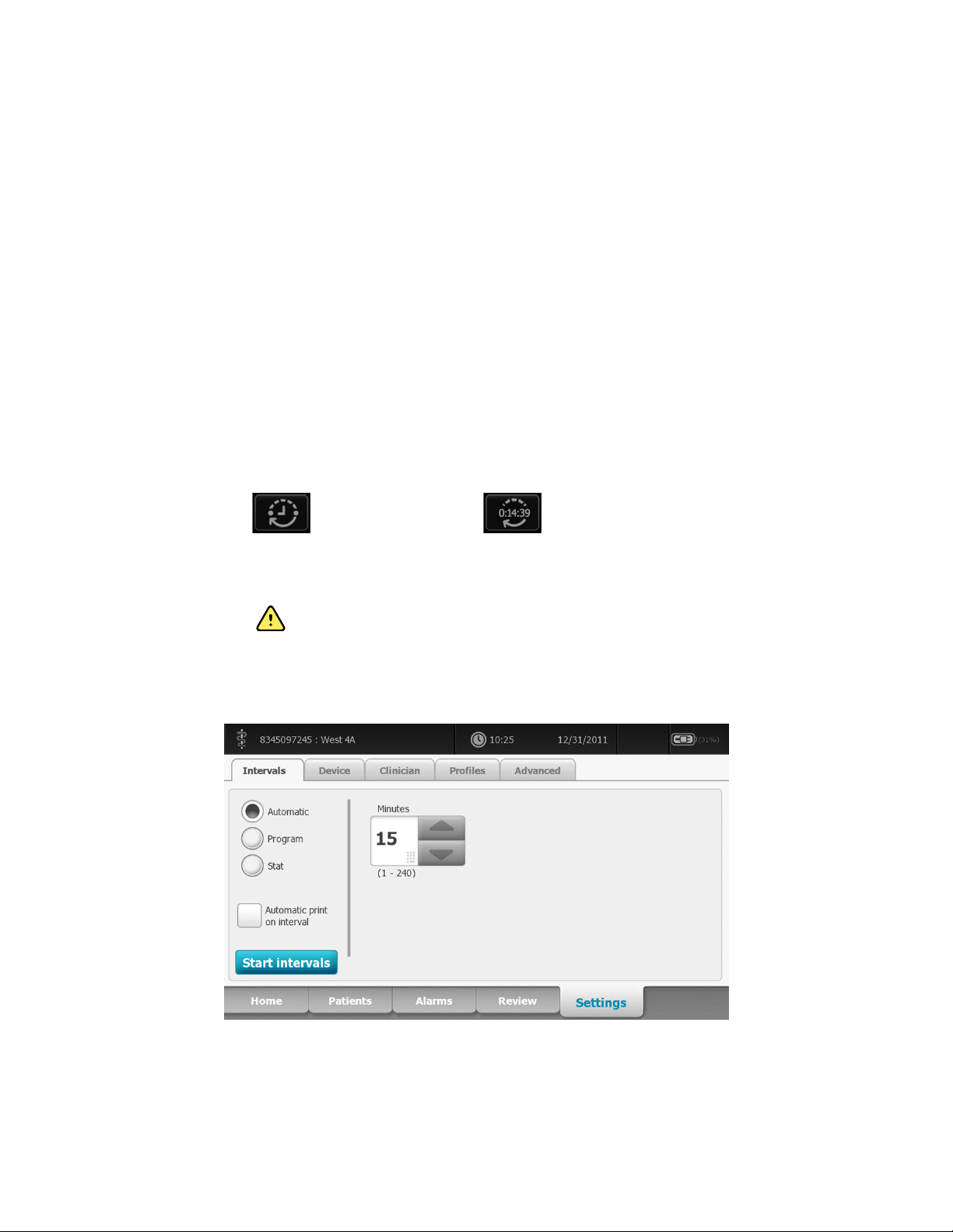
Patient monitoring Welch Allyn Connex® Integrated Wall System
74
1. Properly size the blood pressure cuff and position it around the patient’s bare upper arm.
2. Touch Start to take a measurement.
Interval NIBP measurement
The monitor can take NIBP measurements automatically based on intervals you choose.
The Intervals tab provides all interval features.
From this tab, you can do the following:
• Configure intervals
• Turn off intervals
• Configure the monitor to print automatic measurements as they are completed
When the measurement is complete, the NIBP frame displays the measurement until the next
measurement is complete.
Note During intervals, each automatic and manual save of patient measurements clears
all measurements from Manual parameters frame.
The button changes to a timer ( ), which counts down to the next automatic
measurement.
Automatic measurements continue until you turn off intervals.
Automatic intervals
You can configure the monitor to take automatic NIBP measurements at consistent intervals.
WARNING Patient harm risk. Do not use intervals on neonates out of earshot.
Verify that audio can be heard from where you intend to be.
Note An alarm does not turn off intervals. Subsequent automatic measurements continue
to occur as scheduled.
Start automatic intervals
Follow these steps to configure the monitor to take NIBP measurements at consistent intervals.
Page 81

Directions for use Patient monitoring 75
1. Properly size the blood pressure cuff and position it around the patient’s bare upper arm.
2. On the Home tab, touch .
3. Select Automatic.
4. Use the numeric keypad to enter the length of time between NIBP measurements.
5. Touch Start intervals.
Note Intervals are not available in all profiles. See the Profiles section for
more information.
Program intervals
You can configure the monitor to take automatic NIBP measurements at variable intervals. The
monitor comes with preset interval programs that can be edited to meet your needs. The numbers
below the program name indicate the length of time between each interval in the cycle.
Start program intervals
Follow these steps to configure the monitor to take automatic NIBP measurements at variable
intervals.
Properly size the blood pressure cuff and position it around the patient’s bare upper arm.
1.
2. On the Home tab, touch .
3. Select Program.
4. Touch the desired program.
5. Touch Start intervals.
Create a new program interval or edit an existing program
Follow these steps to create or edit a program interval.
On the Home tab, touch the interval button ( or ).
1.
2. Select Program.
3. Touch the desired program.
Page 82

Patient monitoring Welch Allyn Connex® Integrated Wall System
76
4. Touch the keyboard icon and enter the desired program name.
5. Enter the desired duration and interval settings.
6. Touch Start Intervals.
The new intervals take effect at the start of the next NIBP measurement.
Stat intervals
You can configure the monitor to take NIBP measurements continuously.
When you select the Stat option in the Intervals tab, the monitor takes repeated NIBP
measurements for 5 minutes, starting a new cycle each time the cuff deflates below safe venous
return pressure (SVRP) for 2 seconds.
Current cuff pressures are not dynamically displayed during a Stat reading. The Home tab displays
the NIBP reading from the previous cycle until the current cycle finishes.
Note If you are in Stat intervals, you can stop intervals by touching . If you touch
Start Stat intervals
Follow these steps to start Stat intervals.
Properly size the blood pressure cuff and position it around the patient’s bare upper arm.
1.
2. Select Stat.
3. Touch Start intervals.
WARNING Patient injury risk. If you use Stat mode repeatedly, periodically
observe the patient's limb to ensure that circulation is not impaired and that the cuff
remains in place. Prolonged impairment of circulation or improper cuff position can
cause bruising.
the button twice, you will restart Stat intervals. The control toggles between STOP
and START with each touch.
Stop automatic measurements
Follow these steps to turn off intervals.
Page 83

Directions for use Patient monitoring 77
1. On the Home tab, touch the interval timer button ( ).
2. Touch Stop intervals.
Cancel a measurement that is in progress
Follow these steps to cancel any NIBP measurement that is in progress.
On the Home tab, touch .
The monitor rapidly deflates the cuff, and the screen displays the NIBP cancellation message.
If intervals are turned on, the button changes to a timer ( ), which counts
down to the next automatic measurement.
Configure NIBP alarms
Follow these steps to set alarm limits for systolic and diastolic measurements, and MAP
calculation.
Verify that you are using the Monitor profile, which contains the Alarms tab.
1.
2. Touch the Alarms tab.
3. Touch the NIBP tab.
4. Enter the desired upper and lower alarm limits for systolic and diastolic measurements, and
MAP calculation using the up/down arrow keys or the keypad.
5. Touch the Home tab.
The new alarm settings display in the Alarm Limit control button.
Temperature
Temperature frame
From the temperature frame you can measure patient temperature.
Located in the lower right corner of the Home tab, the temperature frame contains data and
features relevant to temperature measurement. The frame provides different features based on the
profile you are using.
Temperature frame in Monitor profile
Page 84

78 Patient monitoring Welch Allyn Connex® Integrated Wall System
Temperature frame in Spot Check and Triage profiles
Temperature measurement display
In all profiles, the frame can display temperature in Celsius or Fahrenheit. You can configure the
default view in Advanced settings.
Site selection
Remove the temperature probe and touch the Temperature site control to toggle
between sites.
Pediatric axillary
Note Monitors configured with the temperature module and the red rectal probe well and
probe default to the rectal mode.
Rectal
Note The monitor displays the ear mode when it receives a temperature measurement
from the ear thermometer.
Ear
Adult axillary Oral
Page 85

Directions for use Patient monitoring 79
Temperature buttons
The buttons on the right side of the frame enable you to do different tasks depending on the profile
you are using. The availability of functions depends on which profile is selected.
Button name Button image Description
Temperature alarm
Direct mode Touch the button to enter Direct mode.
Configure temperature alarms
Follow these steps to set alarm limits for temperature measurement.
Verify that you are using the Monitor profile, which contains the Alarms tab.
1.
2. Touch the Alarms tab.
3. Touch the Temperature tab.
4. Enter the desired upper and lower alarm limits for temperature using the up/down arrow keys
or the keypad.
5. Touch the Home tab.
The new alarm settings display in the Alarm Limit control button.
This button displays alarm limits and status.
Touch the button to display the Alarms tab.
SureTemp® Plus temperature module
The temperature module uses a thermistor thermometer design and a predictive algorithm to
calculate patient temperatures in the Predictive mode.
WARNING Patient injury risk. Prior to taking a temperature, instruct the patient
not to bite down on the probe as patient injury and damage to the probe may result.
WARNING Patient injury risk. Do not exceed the recommended temperature
measurement durations in Direct mode. Continuous measurement durations of 3
minutes at the oral and rectal sites and 5 minutes at the axillary site are
recommended for accurate measurement. Do not continuously measure beyond 10
minutes in any mode.
WARNING Probe covers are single-use only. Re-use of a probe cover may result
in spread of bacteria and cross-contamination.
WARNING Patient injury risk. Use only Welch Allyn single-use disposable probe
covers. Never take a temperature measurement without a single-use probe cover
securely attached. Failure to use a probe cover can cause patient discomfort from a
heated probe, patient cross-contamination, and inaccurate temperature readings.
Page 86

80 Patient monitoring Welch Allyn Connex® Integrated Wall System
WARNING Patient illness may result from improper use of oral and rectal
temperature probes. Using the incorrect probe may also produce inaccurate
measurements.
• Use only oral probes, identified by a blue ejection button at the top of the probe, to
take oral and axillary temperatures.
• Use only rectal probes, identified by a red ejection button at the top of the probe, to
take rectal temperatures.
WARNING Patient illness or cross-contamination may result from improper
placement of oral and rectal temperature probes in the probe wells.
• Place only oral probes, identified by a blue ejection button at the top of the probe, in
the blue probe wells.
• Place only rectal probes, identified by a red ejection button at the top of the probe, in
the red probe wells.
WARNING Inaccurate measurement risk. Never take an axillary temperature
through the patient's clothing. Carefully place the probe in the axilla, avoiding
contact with other objects or material. Always verify direct contact between the
probe cover and skin.
WARNING Patient injury risk. When taking rectal temperatures, insert the probe
tip only 5/8 inch (approximately 1.5 cm) inside the rectum of adults and only 3/8 inch
(approximately 1 cm) inside the rectum of children to avoid the risk of bowel
perforation.
WARNING Never use a damaged temperature probe. The thermometer consists
of high-quality precision parts and should be protected from severe impact or
shock. Do not use the thermometer if you notice any signs of damage to the probe
or monitor. If the thermometer probe is dropped or damaged, remove it from use
and have it inspected by qualified service personnel.
CAUTION Inaccurate measurement risk. Patient activities such as strenuous
exercise, ingesting hot or cold liquids, eating, chewing gum or mints, brushing teeth,
or smoking may affect oral temperature measurements for up to 20 minutes.
CAUTION Inaccurate measurement risk. Always use new probe covers taken
from the monitor's probe cover box holder to ensure accurate temperature
measurements. Probe covers taken from other places or that haven't stabilized in
temperature may result in inaccurate temperature measurements.
Temperature mode selection
The monitor with the temperature module takes a patient temperature in either Predictive (Normal)
or Direct mode. The default setting is the Predictive mode.
WARNING Inaccurate measurement risk. To ensure optimal accuracy, always
confirm that the correct mode and site are selected.
WARNING Patient injury risk. Do not exceed the recommended temperature
measurement durations in Direct mode. Continuous measurement durations of 3
minutes at the oral and rectal sites and 5 minutes at the axillary site are
recommended for accurate measurement. Do not continuously measure beyond 10
minutes in any mode.
Page 87

Directions for use Patient monitoring 81
Predictive mode
Is a one-time measurement that takes a temperature in approximately 6 to 15 seconds. Removing
the probe from the probe well, loading a probe cover, and holding the probe tip in place at the
measurement site initiates a Predictive mode measurement. The monitor sounds a tone to indicate
the end of a predictive measurement.
Direct mode
Provides continual temperature measurements. For oral and rectal measurements, it is
recommended to measure temperature until the temperature stabilizes or for 3 minutes. For axillary
measurements, it is recommended to measure temperature until the temperature stabilizes or for 5
minutes. The monitor changes to Direct mode approximately 60 seconds after the probe is removed
from the probe well.
CAUTION The monitor does not retain Direct mode temperatures in memory.
Therefore, it is important to note the temperature before removing the thermometer
probe from the measurement site and then manually record it in the patient record.
After 10 minutes of using the Direct mode, the monitor generates a technical alarm condition and
clears the measurement.
Take a temperature in the Predictive mode
WARNING Inaccurate measurement risk. To ensure optimal accuracy, always
confirm that the correct mode and site are selected.
WARNING Patient injury risk. Prior to taking a temperature, instruct the patient
not to bite down on the probe as patient injury and damage to the probe may result.
CAUTION Probe covers are disposable, nonsterilized, and single-use. Probes are
also nonsterilized. Do not autoclave probes and probe covers. Ensure that probe
covers are disposed of according to facility requirements or local regulations.
1. Remove the temperature probe from the probe well.
The monitor sounds a tone as it enters the ready state.
2. Insert the probe into a new probe cover and press the probe handle down firmly.
3. Touch the Temperature site control to choose from these measurement sites: oral,
pediatric axillary, or adult axillary.
4. Hold the probe tip in place at the measurement site.
For oral temperatures, place the probe tip under the patient’s tongue on either side of the
mouth to reach the sublingual pocket and ask the patient to close his/her lips.
Note Do not hand the probe to patients to place in their mouth.
Page 88

82 Patient monitoring Welch Allyn Connex® Integrated Wall System
For axillary temperatures, lift the patient’s arm so that the entire axilla is easily seen and place
the probe tip as high as possible in the mid-axilla. Verify that axillary tissue completely
surrounds the probe tip and place the arm snugly at the patient’s side.
While the measurement is taking place, the temperature frame displays the process indicator.
The monitor sounds a tone when the final temperature is reached (in approximately 6 to 15
5.
seconds). The temperature frame continues to display the temperature in degrees Fahrenheit
and degrees Celsius even after the probe is returned to the probe well.
Note To switch to the Direct mode, touch after you acquire the
Predictive mode measurement. The temperature frame (in the
lower-left corner) changes to "MODE: Direct..." as it switches to the
Direct mode.
The monitor sounds a tone at the start of a Direct mode measurement.
Remove the probe after the temperature measurement is complete and firmly press the eject
6.
button on the top of the probe to release the probe cover.
WARNING Patient injury risk. Do not exceed the recommended
temperature measurement durations in Direct mode. Continuous
measurement durations of 3 minutes at the oral and rectal sites and
5 minutes at the axillary site are recommended for accurate
measurement. Do not continuously measure beyond 10 minutes in
any mode.
Ensure that probe covers are disposed of according to facility requirements or local
regulations.
7. Return the probe to the probe well.
8. Wash your hands to reduce the risk of cross-contamination.
Page 89

Directions for use Patient monitoring 83
Take a temperature in the Direct mode
Direct mode displays the temperature of the probe as long as the probe tip remains in place at the
measurement site and remains within the operating patient temperature range. The patient’s
temperature will reach final equilibrium in approximately 3 minutes at the oral and rectal
measurement sites and approximately 5 minutes at the axillary site.
The monitor enters Direct mode by the following methods.
•
After you complete a Predictive mode measurement, touch to switch from Predictive
to Direct mode. The temperature frame (in the lower-left corner) changes to "MODE: Direct..."
as it switches to the Direct mode.
• Remove the probe from the probe well, load a probe cover, select a temperature site, and
expose the probe to ambient air for more than 60 seconds to switch the monitor to Direct
mode. The temperature frame changes to "MODE: Direct...".
• If you have a patient whose body temperature is below the normal temperature range and you
follow the previous step, the probe sensor identifies this condition and turns off the probe
preheater in order to accommodate the lower body temperature measurement.
WARNING Patient injury risk. Do not exceed the recommended temperature
measurement durations in Direct mode. Continuous measurement durations of 3
minutes at the oral and rectal sites and 5 minutes at the axillary site are
recommended for accurate measurement. Do not continuously measure beyond 10
minutes in any mode.
WARNING Inaccurate measurement risk. To ensure optimal accuracy, always
confirm that the correct mode and site are selected.
WARNING Patient injury risk. Prior to taking a temperature, instruct the patient
not to bite down on the probe as patient injury and damage to the probe may result.
CAUTION Probe covers are disposable, nonsterilized, and single-use. Probes are
also nonsterilized. Do not autoclave probes and probe covers. Ensure that probe
covers are disposed of according to facility requirements or local regulations.
1. Remove the temperature probe from the probe well.
The monitor sounds a tone as it enters the ready state.
2. Insert the probe into a new probe cover and press the probe handle down firmly.
3. Touch the Temperature site control to choose from these measurement sites: oral,
pediatric axillary, or adult axillary.
The temperature frame changes to Direct mode approximately 60 seconds after the probe is
removed from the probe well.
The monitor sounds a tone to indicate the start of a Direct mode measurement.
4. Hold the probe tip in place at the oral or rectal measurement site for a total of 3 minutes and
for 5 minutes at the axillary site.
5. While the measurements are taking place, the temperature frame displays the patient's
continuous temperature measurements in degrees Fahrenheit and degrees Celsius.
Page 90

84 Patient monitoring Welch Allyn Connex® Integrated Wall System
Note The monitor does not retain Direct mode temperatures in memory.
Therefore, it is important to note the temperature before removing
the probe from the measurement site and then manually record it in
the patient record.
6. Remove the probe after the temperature measurement is complete and firmly press the eject
button on the top of the probe to release the probe cover.
7. Return the probe to the probe well to continue taking temperatures in the Predictive mode.
8. Wash your hands to reduce the risk of cross-contamination.
Take a temperature at the rectal site
WARNING Patient injury risk. When taking rectal temperatures, insert the probe
tip only 5/8 inch (approximately 1.5 cm) inside the rectum of adults and only 3/8 inch
(approximately 1 cm) inside the rectum of children to avoid the risk of bowel
perforation.
WARNING Cross-contamination or nosocomial infection risk. Thorough handwashing greatly reduces the risk of cross-contamination and nosocomial infection.
WARNING Patient injury risk. Do not exceed the recommended temperature
measurement durations in Direct mode. Continuous measurement durations of 3
minutes at the oral and rectal sites and 5 minutes at the axillary site are
recommended for accurate measurement. Do not continuously measure beyond 10
minutes in any mode.
WARNING Inaccurate measurement risk. To ensure optimal accuracy, always
confirm that the correct mode and site are selected.
CAUTION Probe covers are disposable, nonsterilized, and single-use. Probes are
also nonsterilized. Do not autoclave probes and probe covers. Ensure that probe
covers are disposed of according to facility requirements or local regulations.
1. Remove the rectal temperature probe from the rectal probe well.
The monitor sounds a tone as it enters the ready state. The Temperature Site Control defaults
to the rectal site.
2. Insert the rectal probe into a new probe cover and press the probe handle down firmly.
3. Separate the patient’s buttocks with one hand. Use the other hand to gently insert the probe
tip only 5/8 inch (1.5 cm) inside the rectum of adults and only 3/8 inch (approximately 1 cm)
inside the rectum of children. The use of a lubricant is optional.
4. Insert the probe so that the tip is in contact with tissue. Continue to separate the buttocks and
hold the probe in place throughout the measurement process. While the measurement is
taking place, the temperature frame displays the process indicator.
Page 91

Directions for use Patient monitoring 85
5. The monitor sounds a tone when the final temperature is reached (in approximately 10 to 13
seconds). The temperature frame continues to display the temperature in degrees Fahrenheit
and degrees Celsius even after the probe is returned to the probe well.
Note To switch to the Direct mode, touch after the Predictive
mode measurement is acquired. The temperature frame (in the
lower-left corner) changes to "MODE: Direct..." as it switches to the
Direct mode. The monitor sounds a tone to indicate the start of a
Direct measurement. Once you are in the Direct mode, continue to
separate the buttocks and hold the probe in place throughout the
measurement process.
Note The monitor does not retain Direct mode temperatures in memory.
Therefore, it is important to note the temperature before removing
the probe from the measurement site and then manually record it in
the patient record.
6. Remove the probe after the temperature measurement is complete and firmly press the eject
button on the top of the probe to release the probe cover.
7. Return the probe to the probe well.
8. Wash your hands to reduce the risk of cross-contamination.
Braun ThermoScan® PRO 4000 thermometer and dock
The thermometer and dock enable you to transfer an ear temperature measurement to the monitor.
The dock also charges the thermometer battery.
Read the thermometer manufacturer's directions for use before attempting to configure, use,
troubleshoot, or maintain the thermometer.
WARNING Liquids can damage electronics inside the thermometer. Prevent
liquids from spilling on the thermometer. If liquids are spilled on the thermometer,
dry off the thermometer with a clean cloth. Check for proper operation and
accuracy. If liquids possibly entered the thermometer, remove the thermometer
from use until it has been properly dried, inspected, and tested by qualified service
personnel.
CAUTION Probe covers are disposable, nonsterilized, and single-use. The
thermometer is also nonsterilized. Do not autoclave the thermometer and probe
covers. Ensure that probe covers are disposed of according to facility requirements
or local regulations.
Page 92

86 Patient monitoring Welch Allyn Connex® Integrated Wall System
CAUTION The thermometer has no user-serviceable parts. If service is required,
call your nearest Welch Allyn Customer Service or Technical Support facility.
CAUTION Store the thermometer and probe covers in a dry location, free from
dust and contamination and away from direct sunlight. Keep the ambient
temperature at the storage location fairly constant and within the range of 50°F to
104°F (10°C to 40°C).
Take a temperature at the ear site
WARNING Probe covers are single-use only. Re-use of a probe cover may result
in spread of bacteria and cross-contamination.
WARNING Inaccurate measurement risk. Use only Braun ThermoScan probe
covers with this thermometer.
WARNING Inaccurate measurement risk. Frequently inspect the probe window
and keep it clean, dry, and undamaged. Fingerprints, cerumen, dust, and other
contaminants reduce the transparency of the window and result in lower
temperature measurements. To protect the window, always keep the thermometer
in the dock when the thermometer is not in use.
CAUTION Inaccurate measurement risk. Before taking a temperature
measurement, make sure that the ear is free from obstructions and excess cerumen
build-up.
CAUTION Inaccurate measurement risk. The following factors can affect ear
temperature measurements for up to 20 minutes:
• The patient was lying on his or her ear.
• The patient's ear was covered.
• The patient was exposed to very hot or very cold temperatures.
• The patient was swimming or bathing.
• The patient was wearing a hearing aid or an ear plug.
CAUTION Inaccurate measurement risk. If ear drops or other ear medications
have been placed in one ear canal, take the temperature in the untreated ear.
Note A temperature measurement taken in the right ear might differ from a measurement
taken in the left ear. Therefore, always take the temperature in the same ear.
Note When the monitor receives an ear temperature measurement, it displays the
measurement on the Home tab. If the Home tab already contains a temperature
measurement, the new measurement overwrites it.
To take a measurement and transfer it to the monitor:
Make sure that the monitor is powered on.
1.
2. Remove the ear thermometer from the dock.
3. Locate the probe cover box in the dock.
4. Firmly push the probe tip into the probe cover box.
When the probe cover is in place, the thermometer turns on automatically.
5. Wait for the ready beep and three dashes to appear on the thermometer display.
6. Fit the probe snugly into the ear canal and then push and release the Start button.
Page 93

Directions for use Patient monitoring 87
• If the probe is positioned correctly in the ear canal the ExacTemp light flashes. When the
thermometer detects an accurate measurement, the ExacTemp light is continuously on, a
long beep signals the end of the measurement, and the display shows the result.
• If the probe is positioned incorrectly in the ear canal or is moved during the measuring
process, the ExacTemp light goes out, a sequence of short beeps sounds, and the error
message POS (position error) appears.
7. When you are finished taking the temperature, press the ejector button to eject the used probe
cover.
8. Return the thermometer to the dock.
The LED on the dock flashes while the measurement is being transferred.
After the transfer is complete, the temperature and the temperature scale appear on the Home
tab according to the monitor settings.
Note Only the latest measurement is transferred to the monitor.
Note Measurements that have already been transferred to the monitor
cannot be transferred again.
For more information about thermometer functionality, refer to the thermometer manufacturer's
directions for use.
Change the temperature scale on the ear thermometer
To switch from Celsius to Fahrenheit, refer to the thermometer manufacturer's directions for use.
Charge the ear thermometer battery
To charge the battery pack:
Place the thermometer in the dock.
•
• Make sure that the monitor is connected to AC power.
• Make sure that the monitor is powered on.
The LED on the dock indicates the charging status of the battery pack:
Orange: The battery pack is charging.
•
• Green: The battery pack is charged.
• Not illuminated: The battery pack is not charging.
Note The battery pack continues to charge while the monitor is in Display power saving
mode.
Note It is strongly recommended that you use only the Welch Allyn rechargeable battery
pack in the thermometer because the dock cannot charge other batteries.
SpO2
SpO2 frame
SpO2 and pulse rate monitoring continuously measures saturation level of oxygen in hemoglobin as
well as the pulse rate in a patient through a pulse oximeter.
The SpO2 frame displays data and controls used in pulse oximetry measurements.
Page 94

Patient monitoring Welch Allyn Connex® Integrated Wall System
88
The frame provides a numeric view and a waveform view of SpO2 data. You can toggle between
views by touching the left side of the frame.
SpO2 numeric view
The numeric view indicates the SpO2 saturation percentage and the pulse amplitude. Features of
this view differ based on the type of sensor enabled and the profile selected.
Nellcor sensor
Monitor profile Spot Check and Triage profiles
Masimo sensor
Monitor profile Spot Check and Triage profiles
Pulse amplitude
The pulse amplitude bar indicates the pulse beat and shows the relative pulse strength. More bars
illuminate as the detected pulse gets stronger.
Response Mode Control
The Response Mode Control allows you to set the SpO2 measurement time to either Normal or
Fast.
Perfusion index
Perfusion Index (PI) is an SpO2 feature available only with Masimo-equipped monitors.
Page 95

Directions for use Patient monitoring 89
PI is a relative reading of pulse strength at the monitoring site. PI is a numerical value that
indicates the strength of the IR (infrared) signal returning from the monitoring site. PI display
ranges from .02 percent (very weak pulse strength) to 20 percent (very strong pulse strength). PI is
a relative number and varies between monitoring sites and from patient to patient, as physiological
conditions vary.
During sensor placement, the PI can be used to evaluate the appropriateness of an application
site, looking for the site with the highest PI number. Placing the sensor at the site with the
strongest pulse amplitude (highest PI number) improves performance during motion. Monitor the
trend of the PI for changes in physiological conditions.
SatSeconds™ alarm management
The SatSeconds feature is an SpO2 alarm management system available only with monitors that
are equipped with Nellcor OxiMax Technology.
The SatSeconds feature is the product of the time and magnitude that a patient falls outside of the
SpO2 alarm limits. For example, three points below the alarm limit for 10 seconds equals 30
SatSeconds. An alarm is triggered only when a desaturation event reaches the SatSeconds limit.
The SatSeconds feature is clinician controlled and can be set to 0, 10, 25, 50, or 100 SatSeconds. If
a desaturation event resolves on its own within the preset time, the clock will automatically reset
and the monitor will not alarm.
Note The SatSeconds feature has a built-in safety protocol that sounds an alarm
SpO2 waveform view
The waveform view shows the real-time SpO2 plethysmograph waveform. You can select the
waveform sweep speed in Advanced settings.
whenever three SpO2 violations of any amount or duration occur within a 1-minute
period.
Measure SpO2 and pulse rate
WARNING Inaccurate measurement risk. Use only Masimo Rainbow SET sensors
and accessories on Masimo-equipped monitors.
Page 96

90 Patient monitoring Welch Allyn Connex® Integrated Wall System
WARNING Inaccurate measurement risk. Use only Nellcor sensors and
accessories on Nellcor-equipped monitors.
WARNING The pulsations from intra-aortic balloon support can increase the
pulse rate displayed on the monitor. Verify the patient's pulse rate against the ECG
heart rate.
WARNING Patient injury risk. Do not attempt to reprocess, recondition, or recycle
any sensors or patient cables. Doing so might damage electrical components.
WARNING Pulse rate measurement might not detect certain arrhythmias
because it is based on the optical detection of a peripheral flow pulse. Do not use
the pulse oximeter as a replacement or substitute for ECG-based arrhythmia
analysis.
WARNING Use the pulse co-oximeter as an early warning device. As you
observe a trend toward patient hypoxemia, use laboratory instruments to analyze
blood samples to better understand the patient's condition.
WARNING The accuracy of SpO2 measurements can be affected by any of the
following:
• elevated levels of total bilirubin
• elevated levels of Methemoglobin (MetHb)
• elevated levels of Carboxyhemoglobin (COHb)
• hemoglobin synthesis disorders
• low perfusion at the monitored site
• the presence of concentrations of some intravascular dyes, sufficient to change the
patient's usual arterial pigmentation
• patient movement
• patient conditions such as shivering and smoke inhalation
• motion artifact
• painted nails
• poor oxygen perfusion
• hypotension or hypertension
• severe vasoconstriction
• shock or cardiac arrest
• venous pulsations or sudden and significant changes in pulse rate
• proximity to an MRI environment
• moisture in the sensor
• excessive ambient light, especially fluorescent
• the use of the wrong sensor
• a sensor applied too tightly
1. Verify that the sensor cable is connected to the monitor.
Page 97

Directions for use Patient monitoring 91
WARNING Patient injury risk. The sensor and extension cable are
intended only for connection to pulse co-oximetry equipment. Do
not attempt to connect these cables to a PC or any similar device.
Always follow the sensor manufacturer's directions for care and
use of the sensor.
2. Clean the application site. Remove anything, such as nail polish, that could interfere with
sensor operation.
Note Do not use disposable sensors on patients who have allergic
reactions to the adhesive.
3. Attach the sensor to the patient according to the manufacturer's directions for use, observing
all warnings and cautions.
Note If a sterile sensor is required, select a sensor that has been
validated for sterilization, and follow the sensor manufacturer's
directions for sterilizing the sensor.
Place the sensor and the NIBP cuff on different limbs to reduce unnecessary alarms when you
monitor these parameters at the same time.
Note A range of sensors is available for different patient sizes and
4. Confirm that the monitor displays SpO2 and pulse rate data within 15 seconds of connection to
the patient.
While SpO2 is being measured, the displayed pulse rate is derived from the sensor. If SpO2 is not
available, the pulse rate is derived from NIBP.
Detaching the sensor during a measurement in Monitor mode triggers an alarm.
If SpO2 is being measured continuously on a patient for an extended period, change the sensor
location at least every three hours or as indicated by the sensor manufacturer's instructions.
Configure SpO2 alarms
Follow these steps to set alarm limits for SpO2 measurements.
Verify that you are using the Monitor profile, which contains the Alarms tab.
1.
2. Touch the Alarms tab.
3. Touch the SpO2 tab.
4. Enter the desired upper and lower alarms limits for SpO2 using the up/down arrow keys or the
keypad.
5. Touch the Home tab.
measurement sites. Consult the sensor manufacturer's instructions
for selecting the correct sensor.
WARNING Patient injury risk. Incorrect sensor application or
excessive duration of sensor use can cause tissue damage. Inspect
the sensor site periodically as directed in the sensor
manufacturer's instructions.
The new alarm settings display in the Alarm Limit control button.
Page 98

Patient monitoring Welch Allyn Connex® Integrated Wall System
92
Set SatSeconds limits
1. Touch the Alarm limit control of the SpO2 frame .
2. Touch the Alarms tab.
3. Touch to select a SatSeconds setting.
4. Touch Home to save your settings and return to the Home tab.
Set Response Mode
To set the Response Mode from the Home tab, the monitor must be in the Monitor profile.
Touch in the SpO2 frame.
The SpO2 frame displays MODE: Fast when Fast mode is selected.
SpHb
Monitors configured with Masimo total hemoglobin can measure hemoglobin (SpHb), SpO2, and
pulse rate. SpHb monitoring continuously measures blood constituents and anemic status in a
patient through a noninvasive SpHb pulse co-oximeter.
SpHb frame
The SpHb frame displays data and controls used in total hemoglobin measurements.
Note SpHb is available only in the Monitor profile.
In this frame, one of two labels appears:
SpHbv indicates the venous calibrated reference for total hemoglobin measurement.
•
• SpHb indicates the arterial calibrated reference for total hemoglobin measurement.
You can specify the reference source in Advanced settings.
The frame provides a numeric view and a graphical trend view of total hemoglobin data. You can
toggle between views by touching the left side of the frame.
SpHb numeric view
The numeric view indicates the total hemoglobin level in either grams per deciliter (g/dL) or
millimoles per liter (mmol/L). You can select the unit of measure in Advanced settings.
Averaging
The averaging button enables you to select the moving window of time used by the parameter to
calculate the SpHb value and update the display: short (approximately 1 minute), medium
(approximately 3 minutes), or long (approximately 6 minutes).
Page 99

Directions for use Patient monitoring 93
SpHb graphical trend view
The graphical trend view presents a trend of the real-time measurements over a user-selected
period. In Advanced settings, you can select the period displayed.
The graph shows total hemoglobin level on the y-axis and time on the x-axis (oldest measurements
on the left to newest measurements on the right). The entire graph updates every 10 seconds.
To the right of the graph, the frame displays the current measurement in numeric format.
Measure SpHb
WARNING Inaccurate measurement risk. Use only Masimo Rainbow SET sensors
and accessories on Masimo-equipped monitors.
WARNING The pulsations from intra-aortic balloon support can increase the
pulse rate displayed on the monitor. Verify the patient's pulse rate against the ECG
heart rate.
WARNING Patient injury risk. Do not attempt to reprocess, recondition, or recycle
any sensors or patient cables. Doing so might damage electrical components.
WARNING Pulse rate measurement might not detect certain arrhythmias
because it is based on the optical detection of a peripheral flow pulse. Do not use
the pulse oximeter as a replacement or substitute for ECG-based arrhythmia
analysis.
WARNING Use the pulse co-oximeter as an early warning device. As you
observe a trend toward patient hypoxemia, use laboratory instruments to analyze
blood samples to better understand the patient's condition.
Page 100

94 Patient monitoring Welch Allyn Connex® Integrated Wall System
WARNING The accuracy of SpHb measurements can be affected by any of the
following:
• elevated levels of total bilirubin
• elevated levels of Methemoglobin (MetHb)
• elevated levels of Carboxyhemoglobin (COHb)
• hemoglobin synthesis disorders
• low perfusion at the monitored site
• the presence of concentrations of some intravascular dyes, sufficient to change the
patient's usual arterial pigmentation
• patient movement
• patient conditions such as shivering and smoke inhalation
• motion artifact
• painted nails
• poor oxygen perfusion
• hypotension or hypertension
• severe vasoconstriction
• shock or cardiac arrest
• venous pulsations or sudden and significant changes in pulse rate
• proximity to an MRI environment
• moisture in the sensor
• excessive ambient light, especially fluorescent
• the use of the wrong sensor
• a sensor applied too tightly
1. Verify that the sensor cable is connected to the monitor.
WARNING Patient injury risk. The sensor and extension cable are
intended only for connection to pulse co-oximetry equipment. Do
not attempt to connect these cables to a PC or any similar device.
Always follow the sensor manufacturer's directions for care and
use of the sensor.
2. Verify that you are using the Monitor profile.
3. Clean the application site. Remove anything, such as nail polish, that could interfere with
sensor operation.
Note Do not use disposable sensors on patients who have allergic
reactions to the adhesive.
4. Attach the sensor to the patient according to the manufacturer's directions for use, observing
all warnings and cautions.
Note If a sterile sensor is required, select a sensor that has been
validated for sterilization, and follow the sensor manufacturer's
directions for sterilizing the sensor.
Place the sensor and the NIBP cuff on different limbs to reduce unnecessary alarms when you
monitor these parameters at the same time.
 Loading...