

Page 1
Welch Allyn Connectivity Server
Programmer’s guide
Software version 2.6x
Page 2

ii Welch Allyn Connectivity Server
© 2013 Welch Allyn. All rights are reserved. To support the intended use of the product described in this
publication, the purchaser of the product is permitted to copy this publication, for internal distribution only,
from the media provided by Welch Allyn. No other use, reproduction, or distribution of this publication, or
any part of it, is permitted without written permission from Welch Allyn.
Welch Allyn assumes no responsibility for any injury to anyone, or for any illegal or improper use of the
product, that may result from failure to use this product in accordance with the instructions, cautions,
warnings, or statement of intended use published in this manual.
Welch Allyn, Acuity, AcuityLink, Propaq, Micropaq are registered trademarks of Welch Allyn. Sun, Solaris
and Java are registered trademarks of Sun Microsystems, Inc. Emergin is a registered trademark of
Emergin, Inc.
For patent information, please visit www.welchallyn.com/patents.
Software in this product is copyright Welch Allyn or its vendors. All rights are reserved. The software is
protected by United States of America copyright laws and international treaty provisions applicable
worldwide. Under such laws, the licensee is entitled to use the copy of the software incorporated with
this instrument as intended in the operation of the product in which it is embedded. The software may not
be copied, decompiled, reverse-engineered, disassembled or otherwise reduced to human-perceivable
form. This is not a sale of the software or any copy of the software; all right, title and ownership of the
software remain with Welch Allyn or its vendors.
For information about any Welch Allyn product, visit www.welchallyn.com/about/company/locations.htm.
Manual 80018556 Ver A
Welch Allyn Protocol, Inc.
8500 SW Creekside Place
Beaverton, Oregon 97008-7101 USA
Regulatory Affairs Representative
Welch Allyn Limited
Navan Business Park
Dublin Road, Navan
County Meath, Republic of Ireland
www.welchallyn.com
Page 3

Contents
1 - Introduction .............................................1
2 - System overview.........................................5
iii
Intended use .....................................................1
Conventions .....................................................2
Warning and note .................................................2
Related documents................................................3
Welcome!.......................................................5
Data interface provided by the Welch Allyn Connectivity Server (WACS) ......6
Data transfer and storage within the Acuity System network ...............7
3 - HL7 standard protocols...................................11
Health Level Seven Standard .......................................11
HL7 low-level protocol ............................................12
HL7 segment-level protocols .......................................12
4 - WACS outbound HL7 protocols ............................15
Overview: Outbound HL7 Vital-sign Observations module ................16
Labels and attributes of outbound segments ...........................17
Outbound patient identification fields.................................21
Outbound vital-sign tags and filters ..................................22
Reconfiguring WACS outbound observation settings ....................24
5 - WACS outbound HL7 messages ...........................27
Unsolicited observation message
ORU^R01/ACK^R01 .............................................28
Query for results of observation message
QRY^R02/ORF^R04..............................................30
Query by parameter
QBP^Q11/RSP^Z90 ..............................................33
Query by ID.....................................................36
Query by location ................................................38
6 - Inbound ADT HL7 messages ..............................41
Overview: Inbound HL7 ADT Data module ............................42
How an Acuity System uses ADT information ..........................43
ADT messages accepted and stored by WACS .........................46
Examples of ADT messages........................................52
Reconfiguration of ADT services ....................................54
Page 4

iv Contents Welch Allyn Connectivity Server
7 - XML interface ..........................................55
8 - Contacts and specifications ...............................57
Contact information ..............................................57
Specifications ...................................................57
Page 5

1
1
Introduction
Intended use
The Welch Allyn Connectivity Server (WACS) is an option to the Welch Allyn Acuity
Central Monitoring System. WACS consists of a server platform on which one or more of
the following software options are installed:
• The Web Server option makes Adobe®Portable Document Format (PDF) printout files
available from the Acuity System to certain Web browsers.
• The AcuityLink®option consists of Clinician Notifier software for non-proprietary
mobile devices and administrative software for WACS. Mobile devices running the
Clinician Notifier software deliver patient alarm information and realtime waveforms
gathered from patient monitors connected to the Acuity Central Monitoring System.
The software enables administrators to track the status of clinician-patient
assignments, and it enables clinicians to track, respond to and view Acuity System
patient alarms, view realtime patient waveforms and view historical alarm details and
waveforms.
• The HL7 Interface options support the following features using HL7 messaging
protocol: export of vital-signs data from the Acuity Central Monitoring System to
hospital CIS/HIS systems, and import of ADT data from hospital clinical information
systems/hospital information systems (CIS/HIS) to the Acuity System.
• The WACS Barcode Scanner option allows clinicians to enter patient IDs and room
numbers into the Acuity System using barcode scanners on some mobile devices
running Clinician Notifier software.
• The Third Party Data Stream Interface option supports sending patient alarms and
equipment alerts in XML format to third party interfaces.
®
WACS is to be used by authorized health care professionals using standard institutional
procedures and good clinical practice guidelines for patient monitoring. Staff training in
the operation of WACS is essential for optimal use. Users should be skilled at the level of
clinicians, clinical administrators and hospital administrators, with the knowledge and
experience to acquire and interpret patients’ vital signs. Each of these roles is assigned
and associated with specific privileges and scopes. Access privileges are controlled
through passwords.
Individuals using WACS should be familiar with its operation as described in this manual,
and they should understand all warnings and cautions in the manual.
Page 6
2 Introduction Welch Allyn Connectivity Server
Conventions
The CE Mark and Notified Body Registration Number signify that the
product meets all essential requirements of European Medical Device
Directive 93/42/EEC.
WARNING Indicates conditions or practices that could lead to illness, injury, or
death.
Warning and note
WARNING HL7 configuration must be performed only by qualified personnel
who are familiar with the HL7 Standard and with local implementation of the
WACS HL7 Interface. Improper configuration of the HL7 Interface can cause
unexpected and unintended cessation of patient vital-signs data transfer.
Note
In compliance with the U.S. Department of Health and Human Services Health
Insurance Portability and Accountability Act (HIPAA), do not transfer or save
patient data or information using any unsecured or public computer.
Page 7

Programmer’s Guide Introduction 3
Related documents
Document
Welch Allyn Connectivity Server (WACS)
Welch Allyn Connectivity Server (WACS) CD-ROM (English):
Welch Allyn Connectivity Server directions for use
Welch Allyn Connectivity Server programmer’s guide
AcuityLink Clinician Notifier directions for use
Acuity and Mobile Acuity LT Central Monitoring System
Directions for use
Acuity and Mobile Acuity LT Central Monitoring Systems directions for use and in-service guide CD-ROM
(multilanguage):
Acuity and Mobile Acuity LT Central Monitoring Systems directions for use
Acuity Central Monitoring System in-service guide (English)
Installation guides (printed)
Mobile Acuity LT System installation guide (En, Fr, Ger, Sp, It. Pol)
Quick card
Acuity System icons (English, printed)
Welch Allyn Monitors
Micropaq Monitor directions for use CD-ROM (multilanguage)
Propaq LT Monitor directions for use CD-ROM (multilanguage)
Propaq CS Monitor directions for use CD-ROM (multilanguage)
Propaq Encore Monitor directions for use CD-ROM (multilanguage)
Welch Allyn 1500 Patient Monitor directions for use CD-ROM (multilanguage)
Page 8

4 Introduction Welch Allyn Connectivity Server
Page 9
5
2
System overview
Welcome!
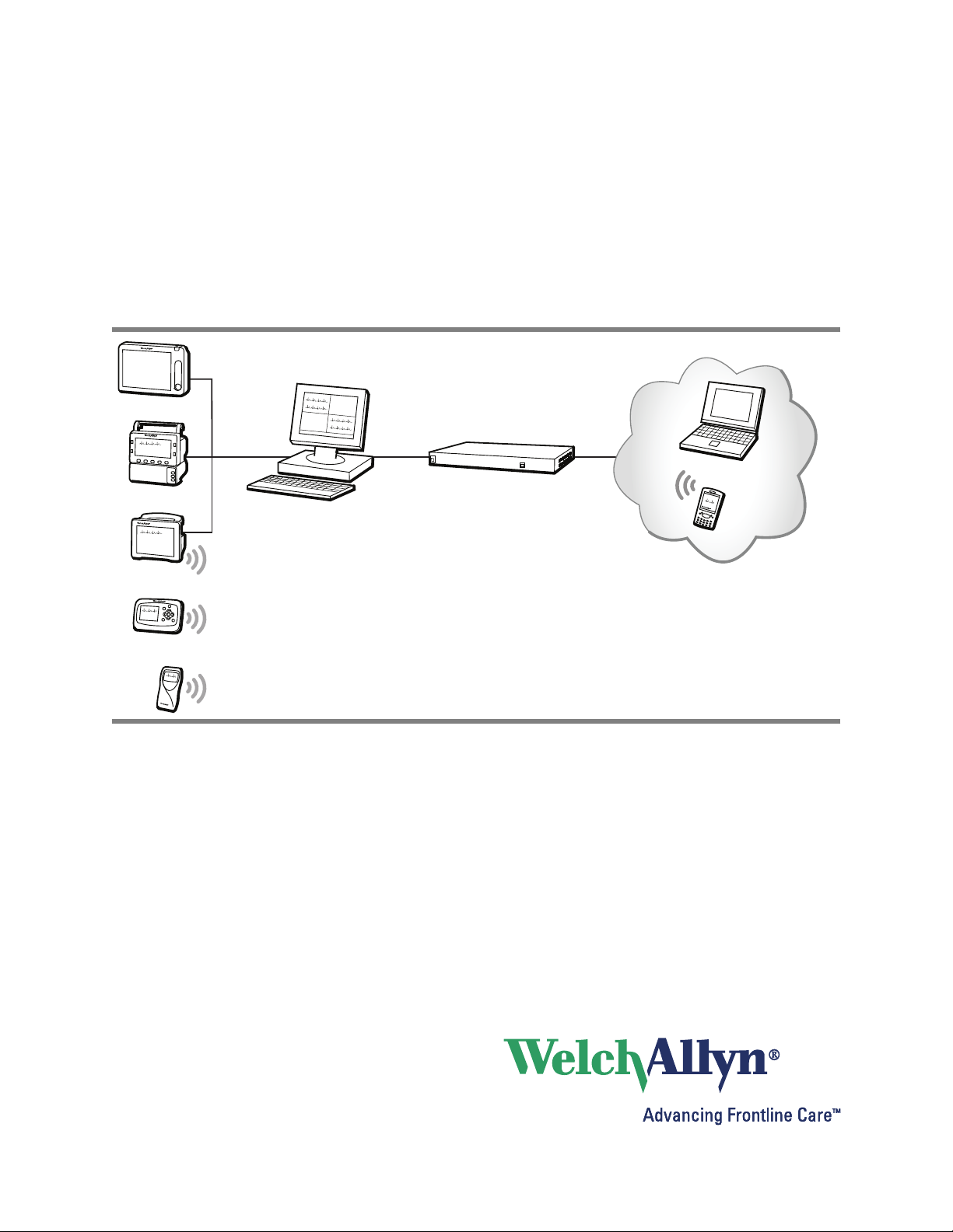
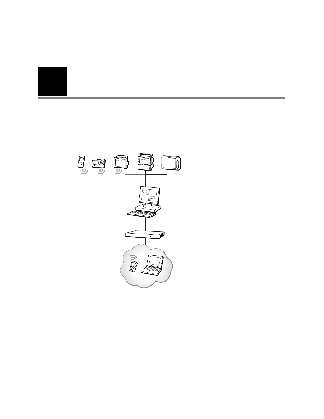
The Acuity Central Monitoring System is a real-time patient monitoring system that
collects and displays vital-sign information for multiple patients over the Welch Allyn
FlexNet™ network.
Welch Allyn patient monitors
Acuity Central Station
Welch Allyn Connectivity Server (WACS)
AcuityLink option
Web Server option
HL7 Interface option
Third-Party Data Stream Interface option
Within the network:
Mobile devices running the Clinician Notifier program
Facility computer used by administrators
This document contains specifications intended as a guide for software developers to
develop the HL7 or XML interface between a facility-controlled clinical information system
(CIS or HIS) and an Acuity System. It is assumed that users of this guide are familiar with
applicable HL7 standards or XML standards, and that users have standards available for
reference.
For information about further configuring the WACS HL7 settings for your facility, see the
Welch Allyn Connectivity Server Directions for Use, which describes using the WACS HL7
Manager pages to configure the HL7 interface.
Page 10

6 System overview Welch Allyn Connectivity Server
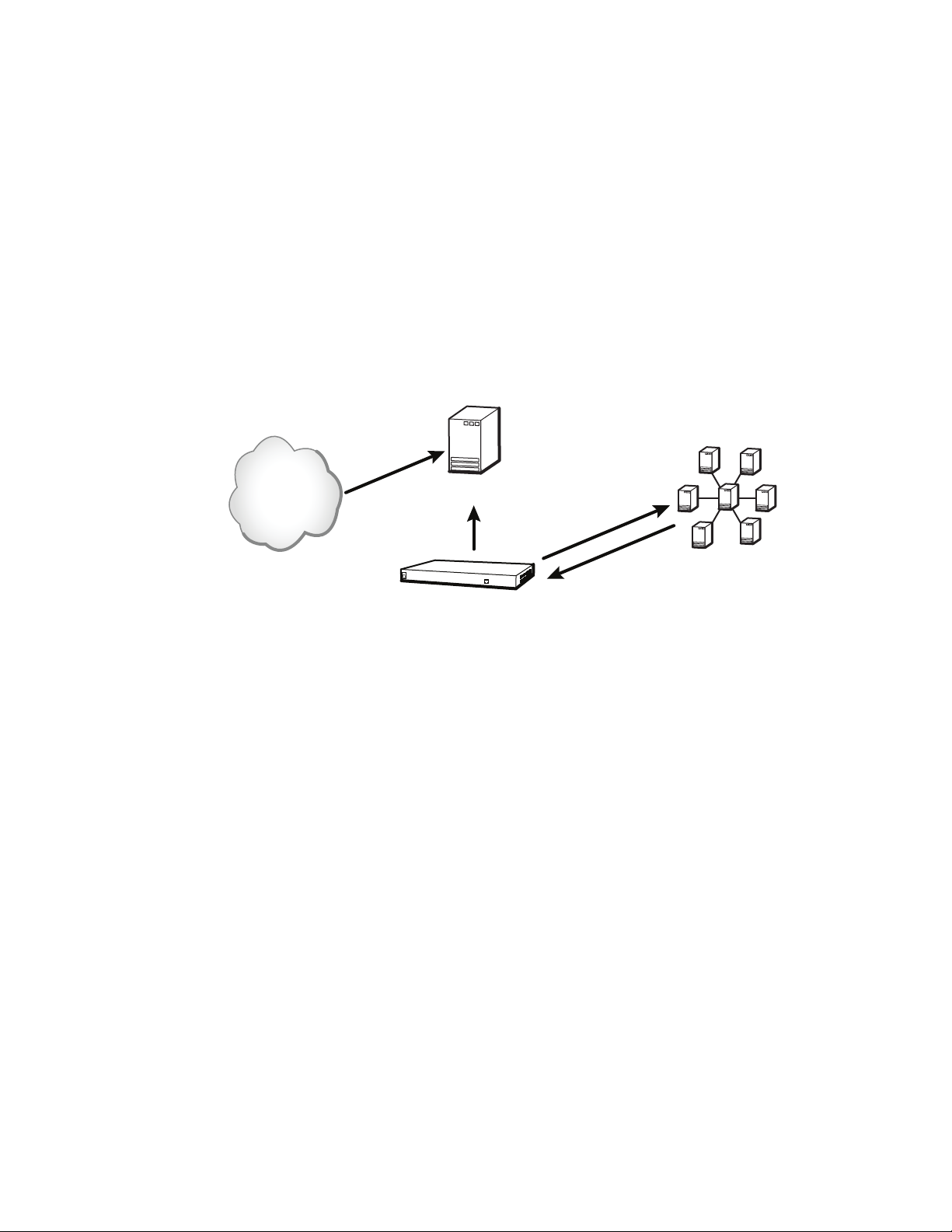
Data interface provided by the Welch Allyn Connectivity Server (WACS)
The WACS option to the Acuity Central Monitoring System is able to provide these data
interface options:
• HL7 (Health Level 7) Interface option
• Third-Party Data Stream Interface option (XML format)
Either WACS data interface option can include one or both of these distinct modules.
• Inbound HL7 ADT Data module: Admit/discharge/transfer (ADT) data from your CIS or
HIS to WACS. WACS uses the Acuity System network to send ADT information to the
Acuity Central Monitoring System for storage.
• Outbound HL7 Vital-sign Observations module: Numeric patient vital-sign
observations from WACS to your facility-controlled clinical or hospital information
system (CIS or HIS).
Acuity Central
Station
VPN
Internet
Hardwired Welch
Allyn monitors
Terminal server
Switch Access point
Welch Allyn
Connectivity
Server (WACS)
Access point Mobile device
Facility backbone
Acuity network
Wireless Welch
Allyn monitors
Wireless LAN
Wireless LAN
NTP server
CIS/HIS
Client browser
Facility network
Page 11

Programmer’s Guide System overview 7
Data transfer and storage within the Acuity System network
The Acuity System stores patient data for variable amounts of time, depending upon
Acuity System license configuration.
Data export from patient monitors to the Acuity System
Welch Allyn portable patient monitors store vital-sign data and send it to the Acuity
System in the following ways:
Table 1. Patient monitor data storage and export to the Acuity System
Patient Monitor Means of data export to
Hardwired monitors:
®
Propaq
Encore,
Propaq CS
Hardwired Welch
Allyn 1500 Patient
Monitor
Wireless monitors:
Propaq CS, Propaq LT
and Micropaq
®
Acuity System
Unshielded twisted pair
(UTP)
Ethernet Stream Data stored up to 24
802.11 wireless LAN Stream Propaqs: Data stored
Mode of data
export to Acuity
System during
normal conditions
Stream Data stored up to
Patient monitor
data storage
during temporary
disconnection or
dropout
monitor storage
capacity
hours
up to monitor
storage capacity
Micropaq: No
storage
Data export to
Acuity System
after temporary
disconnection or
dropout
Trends data only,
sent in batch mode
Trends data only,
sent in batch mode
Propaqs: Trends data
only, sent in batch
mode
Micropaq: data lost
Page 12

8 System overview Welch Allyn Connectivity Server
Data storage at the Acuity System
The Acuity System stores data for a period determined by the Full Disclosure license
configuration.
Storage during Acuity connection to WACS
Table 2. Acuity System data storage configurations and Acuity System data export to WACS
Acuity System data storage configuration WACS capability for data receipt
Zero hours Continuous
24 hours Query for most recent 24 hours
96 hours Query for most recent 96 hours
a. Data is available for a period up to the Acuity Full Disclosure capability, but unsolicited push interfaces
are usually configured to a shorter period to avoid swamping the CIS/HIS.
Storage after Acuity disconnects from WACS or patient monitor
a
Table 3. Examples of Acuity System data export after disconnection
WACS HL7 message
configuration
Unsolicited observation (push)
from WACS to CIS
15-minute intervals
2-hour disconnect period Behavior upon reconnection
Patient monitor disconnected from Acuity
System
Or
Acuity System disconnected from WACS
server
Acuity System sends 8 sets of vitalsign observations, covering the last
two hours
Page 13

Programmer’s Guide System overview 9
Data exported from the Acuity System to WACS
The Acuity System exports the following vital-sign data:
Table 4. Numeric vital-sign data exported from Acuity Systems to WACS
Vital sign Units Default units Preferred HL7 tag
Heart rate BPM (1/min) BPM (1/min) Heart Rate
Temperature 1, 2 DegF (°F),
SpO
2
In mmHg, kPa, % mmHg CO2(In)
CO
2
Ex mmHg, kPa, % mmHg CO2(Ex)
CO
2
RESP Br/M (1/min) Br/M (1/min) RR/BR
NIBP (DIA / SYS / MEAN) mmHg mmHg NIBP
IBP - 1 (DIA / SYS / MEAN)
unlabeled
arterial
intracranial
umbilical artery
umbilical vein
pulmonary artery
central venous
IBP - 2 (DIA / SYS / MEAN)
unlabeled
arterial
intracranial
umbilical artery
umbilical vein
pulmonary artery
central venous
PVCRate PVC/Min (1/min) PVC/Min (1/min) PVC
DegC (°C)
Per cent (%) Per cent (%) SPO2
mmHg mmHg
mmHg mmHg
DegC (°C) Temperature
(OBX-3)
IBP1
ART
ICP
UA
UV
PA
CVP
IBP2
ART
ICP
UA
UV
PA
CVP
Page 14

10 System overview Welch Allyn Connectivity Server
Page 15

11
3
HL7 standard protocols
This chapter describes basic HL7 data structure as outlined in the Health Level Seven
Messaging Standard.
Information in this chapter is organized as follows:
Health Level Seven Standard........................................11
HL7 low-level protocol.............................................12
HL7 segment-level protocols........................................12
Health Level Seven Standard
The Welch Allyn HL7 Interface option closely follows the data structure outlined in the
Health Level Seven Version 2.4 Messaging Standard.
The following excerpt is taken from section 7.3 and section 7.4 of this standard:
“Many report headers (OBR) may be sent beneath each patient segment, with many
separate observation segments (OBX) beneath each OBR. Note segments (NTE) may be
inserted after any of the above segments. The note segment applies to the entity that
immediately precedes it, i.e., the patient if it follows the PID segment, the observation if it
follows the OBR segment, and the individual result if it follows the OBX segment.”
One result segment (OBX) is transmitted for each vitals component (such as Heart rate or
RR/BR).
For updated information regarding this standard, see www.hl7.org/.
Page 16

12 HL7 standard protocols Welch Allyn Connectivity Server
HL7 low-level protocol
This section describes the low-level format of HL7 packet frames.
Packet frames
HL7 frames that are exchanged between the server and the client describe both sent and
received data.
Table 5. HL7 packet frame: low-level format
Packet description Content Size (bytes)
Start block 0x0B ASCII <VT> 1
Body variable bytes variable
End block 0x1C ASCII <FS> 1
Carriage return 0x0D ASCII <CR> 1
HL7 segment-level protocols
This section describes HL7 message hierarchy and delimiters, segment notation and
date/time format.
Message hierarchy and message delimiters
Group
Groups
Segment notation
Table 6. HL7 segment notation: mandatory, optional and repeating
Segments
|Fields|
&components&
^subcomponents^
Notation example Definition
PID This segment is mandatory.
[PID] This segment is optional.
{IN1} This segment is mandatory, and it can repeat.
[{NK1}] This segment is both optional and repeating.
Page 17

Programmer’s Guide HL7 standard protocols 13
Time/date in HL7 segments
When importing vital-sign data into an electronic patient-charting application, use the
timestamp associated with the OBR for the vital-signs record in the chart.
Format
Date and time in the HL7 segments are represented in this format:
YYYYMMDDHHMMSS.mmm±TZTZ
• Displayed time is local.
• Hours are in the range 0-23.
• Seconds (SS) are followed by the following:
3-digit millisecond value (which appears as 000 if no other value is provided)
+ora-
4-digit time-zone code
Example of HL7 time/date format:
26 January 2009, at 0.193 seconds past 12:22:02 PM, Pacific time (8 hours behind GMT):
20090126122202.193-0800
Page 18

14 HL7 standard protocols Welch Allyn Connectivity Server
Page 19

15
4
WACS outbound HL7 protocols
The WACS Outbound HL7 Vital-sign Observations module uses JavaTMprocesses to read
patient data files from an Acuity System and forward the messages to a CIS server.
This chapter describes WACS protocols used in the Outbound HL7 Observations module.
The WACS protocols closely follow the data structure outlined in the Health Level Seven
Version 2.4 Messaging Standard.
Information in this chapter is organized as follows:
Overview: Outbound HL7 Vital-sign Observations module .................16
Labels and attributes of outbound segments ...........................17
Outbound patient identification fields .................................21
Outbound vital-sign tags and filters ...................................22
Reconfiguring WACS outbound observation settings .....................24
Page 20
16 WACS outbound HL7 protocols Welch Allyn Connectivity Server
Overview: Outbound HL7 Vital-sign Observations module
Patient vital-sign observations are transferred to the CIS server in this manner:
Acuity System
network
SQL database
Patient data
WACS
10.250.100.201:5600
Initiate connection to
WACS IP + port
HL7 outbound
message
Clinical information system
(CIS)
Outbound HL7 patient data messaging
1. WACS is configured to accept requests on a preconfigured TCP port (usually in the
5600-5700 range).
2. Once a connection is established between the WACS system and the CIS, and once
the optional handshake and optional authentication are complete, The HL7 session
begins.
3. WACS sends observations to the CIS in one of these ways, depending on the
configured model:
• Push model: WACS sends information to the CIS at configurable intervals
• Pull model: WACS listens for incoming queries from the CIS
The system maintains an open connection for as long as possible. Connections can
be re-established if fatal errors or program crashes occur on either end. The WACS
master program uses exit codes and return values of the interface components to
manage child processes.
Page 21

Programmer’s Guide WACS outbound HL7 protocols 17
Labels and attributes of outbound segments
The following table defines requirement labels for outbound segments.
Table 7. Requirement labels for outbound segments
Label Requirement Description
R Required Causes an error condition if missing
O Optional May be used by WACS/CIS if present
C Conditionally Required May cause an error condition if missing; dependent on other factors or fields
N Not used Causes an error condition if present
I Ignored Not used, whether present or missing
F Future Not used, whether present or missing
HL7 attributes of OBR (observation request) segments
Table 8. HL7 attributes – OBR – observation request segment
SEQ LEN DT OPT RP# TBL# Item # Element name WACS
1 4 SI O 00237 Set ID - OBR R
2 22 EI C 00216 Placer Order Number C
3 22 EI C 00217 Filler Order Number N
4 250 CE R 00238 Universal Service Identifier R
5 2 ID X 00239 Priority - OBR N
6 26 TS X 00240 Requested Date/Time R
7 26 TS C 00241 Observation Date/Time N
8 26 TS O 00242 Observation End Date/Time N
9 20 CQ O 00243 Collection Volume N
10 250 XCN O Y 00244 Collector Identifier N
11 1 ID O 0065 00245 Specimen Action Code N
12 250 CE O 00246 Danger Code N
13 300 ST O 00247 Relevant Clinical Information N
14 26 TS C 00248 Specimen Received Date/Time N
15 300 CM O 0070 00249 Specimen Source N
16 250 XCN O Y 00226 Ordering Provider N
17 250 XTN O Y/2 00250 Order Callback Phone Number N
18 60 ST O 00251 Placer Field 1 N
19 60 ST O 00252 Placer Field 2 N
20 60 ST O 00253 Filler Field 1 N
21 60 ST O 00254 Filler FIeld 2 N
22 26 TS C 00255 Results Rpt/Status Chng -
Date/Time
23 40 CM O 00256 Charge to Practice N
24 10 ID O 0074 00257 Diagnostic Serv Sect ID N
requirement
N
Page 22

18 WACS outbound HL7 protocols Welch Allyn Connectivity Server
Table 8. HL7 attributes – OBR – observation request segment (continued)
SEQ LEN DT OPT RP# TBL# Item # Element name WACS
25 1 ID C 0123 00258 Result Status N
26 400 CM O 00259 Parent Result N
27 200 TQ O Y 00221 Quantity/Timing N
28 250 XCN O Y/5 00260 Result Copies To N
29 200 CM O 00261 Parent N
30 20 ID O 0124 00262 Transportation Mode N
31 250 CE O Y 00263 Reason for Study N
32 200 CM O 00264 Principal Result Interpreter N
33 200 CM O Y 00265 Assistant Result Interpreter N
34 200 CM O Y 00266 Technician N
35 200 CM O Y 00267 Transcriptionist N
36 26 TS O 00268 Scheduled Date/Time N
37 4 NM O 01028 Number of Sample Containers N
38 250 CE O Y 01029 Transport Logistics of Collected
Sample
39 250 CE O Y 01030 Collector’s Comment N
40 250 CE O 01031 Transport Arrangement
Responsibility
41 30 ID O 0224 01032 Transport Arranged N
42 1 ID O 0225 01033 Escort Required N
43 250 CE O Y 01034 Planned Patient Transport
Comment
44 250 CE O 0088 00393 Procedure Code N
45 250 CE O Y 0340 01316 Procedure Code Modifier N
46 250 CE O Y 0411 01474 Placer Supplemental Service
Information
47 250 CE O Y 0411 01475 Filler Supplemental Service
Information
requirement
N
N
N
N
N
OBR segment example
OBR|1|||VITALS^Vital Signs^WAP|||20090127093400.000-0800
Page 23

Programmer’s Guide WACS outbound HL7 protocols 19
HL7 attributes of PID (patient ID) segments
Table 9. HL7 attributes – PID – patient ID segment
SEQ LEN DT OPT RP# TBL# Item# Element name WACS
1 4 SI O 00104 Set ID - PID R
2 20 CX B 00105 Patient ID R
3 20 CX R Y 00106 Patient Identifier List R
4 20 CX B Y 00107 Alternate Patient ID - PID I
5 48 XPN R Y 00108 Patient Name O
6 48 XPN O Y 00109 Mother’s Maiden Name I
7 26 TS O 00110 Date/Time of Birth I
8 1 IS O 0001 00111 Sex I
9 48 XPN O Y 00112 Patient Alias I
10 80 CE O Y 0005 00113 Race I
11 106 XAD O Y 00114 Patient Address I
12 4 IS B 0289 00115 County Code I
13 40 XTN O Y 00116 Phone Number - Home I
14 40 XTN O Y 00117 Phone Number - Business I
15 60 CE O 0296 00118 Primary Language I
16 80 CE O 0002 00119 Marital Status I
17 80 CE O 0006 00120 Religion I
18 20 CX O 00121 Patient Account Number C
19 16 ST B 00122 SSN Number - Patient I
20 25 DLN O 00123 Driver's License Number -
Patient
21 20 CX O Y 00124 Mother's Identifier I
22 80 CE O Y 0189 00125 Ethnic Group I
23 60 ST O 00126 Birth Place I
24 1 ID O 0136 00127 Multiple Birth Indicator I
25 2 NM O 00128 Birth Order I
26 80 CE O Y 0171 00129 Citizenship I
27 60 CE O 0172 00130 Veterans Military Status I
28 80 CE O 0212 00739 Nationality I
29 26 TS O 00740 Patient Death Date and
Time
30 1 ID O 0136 00741 Patient Death Indicator I
requirement
I
I
PID segment examples
Edgar A Van Goe with Primary ID 9582173 and no Amended ID:
PID|1|9582173|9582173||Van Goe^Edgar^A|||||||||||||9582173
Edgar A Van Goe with Primary ID 9582173 and Amended ID 867509:
PID|1|867509|867509||Van Goe^Edgar^A|||||||||||||867509
Page 24

20 WACS outbound HL7 protocols Welch Allyn Connectivity Server
HL7 attributes of OBX (observation/result) segments
Table 10. HL7 attributes – OBX – observation/result segment
SEQ LEN DT OPT RP/# TBL# ITEM# Element name WACS
1 4 SI O 00569 Set ID - OBX R
2 2 ID C 0125 00570 Value Type R
3 250 CE R 00571 Observation Identifier R
4 20 ST C 00572 Observation Sub-ID C
a
5 65536
6 250 CE O 00574 Units R
7 60 ST O 00575 References Range C
8 5 IS O Y/5 0078 00576 Abnormal Flags C
9 5 NM O 00577 Probability I
10 2 ID O Y 0080 00578 Nature of Abnormal Test N
11 1 ID R 0085 00579 Observation Result Status N
12 26 TS O 00580 Date Last Observation Normal
13 20 ST O 00581 User Defined Access Checks N
14 26 TS O 00582 Date/Time of the Observation R
15 250 CE O 00583 Producer's ID N
16 250 XCN O Y 00584 Responsible Observer N
17 250 CE O Y 00936 Observation Method N
18 22 EI O Y 01479 Equipment Instance Identifier N
19 26 TS O 01480 Date/Time of the Analysis N
*CY
b
00573 Observation Value R
Value
requirement
N
a. The length of the observation field is variable, depending upon value type. See OBX-2 value type.
b. May repeat for multipart, single answer results with appropriate data types, e.g., CE, TX, and FT data types.
OBX segment example
OBX|1|ST|Heart Rate^Heart Rate^WAP||80|^BPM||||||||20090127093400.000-0800
Page 25

Programmer’s Guide WACS outbound HL7 protocols 21
Outbound patient identification fields
Patient ID information is confirmed at the Acuity Central Station in the Patient ID Setup
window. WACS forwards an outbound patient ID segment that includes at least one of
these ID fields: PID-2, PID-3, and PID-18. By default, all of the fields are populated.
Export multiple ID fields from WACS, such as name and ID number. This enables
detection of obvious identification errors. Since monitors can move easily from location to
location, patient room number alone is an unreliable means of identifying patients.
WACS can export these patient ID fields:
• Patient ID number: A primary identification number, such as a medical record number,
account number or a patient’s personal ID number (such as a social security number).
If this number is input incorrectly, it cannot be altered.
• Amended patient ID number: An alternate ID that can be associated with the patient.
This ID can be entered in the Acuity System Patient ID Setup window, in the
Amended ID field.
• Patient last name
• Patient first name
• Patient middle initial
Note
• Patient location: A room number
The Acuity System accepts middle initial only (not middle name).
Page 26

22 WACS outbound HL7 protocols Welch Allyn Connectivity Server
Outbound vital-sign tags and filters
WACS generates the vital-sign tags and filters described in this section.
By default, missing tags or tag errors cause the HL7 interface to reject the request or
query. If part of a message or reply is valid, WACS ignores or rejects the erroneous
portion and returns only the valid reply.
This setting is configurable in the WACS HL7 Manager pages (see the Welch Allyn
Connectivity Server directions for use).
Vital-sign tags
Vital-sign tags include vital sign name tags, unit tags and optional status fields.
Table 11. WACS HL7 sublevel tags for vital signs (OBX-4)
Vital-sign sub-level HL7 OBX-4 tag
Temperature 1 (Temperature) 1
Temperature 2 (Temperature) 2
Systolic Blood Pressure (IBP-1, IBP-2, NIBP) SYS
Diastolic Blood Pressure (IBP-1, IBP-2, NIBP) DIA
Mean Blood Pressure (IBP-1, IBP-2, NIBP) MEAN
Table 12. WACS HL7 tags for units (OBX-6)
BPM (1 / min)
DegC (°C)
DegF (°F)
Percent (%)
mmHg
kPa
Br/M (1 / min)
PVC/Min (1 / min)
Table 13. Optional WACS HL7 status fields (OBX-8 abnormal flag segment)
OBX-8 abnormal
flag segment
Patient monitor/Acuity
System notation
Description
Valid value
< (---) Under range, below absolute low on the instrument scale
> (+++) Over range, above absolute high on the instrument scale
? Invalid For example, no valid SpO2 numeric is produced when the SpO2
sensor is removed from the patient’s finger.
Page 27

Programmer’s Guide WACS outbound HL7 protocols 23
Vital-sign numerics filters
One of the following vital-sign numerics filters must be configured for the WACS server:
Table 14. WACS vital-sign filters
Filter Function
Median For an odd number of sample points, WACS sorts the data in descending order and returns the middle
Closest Returns the data closest to the given reference point.
(median) data point. For example, for the values 56, 72, 96, 82 and 78, the returned value is 78.
For an even number of sample points, WACS returns either the average (mean) or one of the two
middle points. For example, for the values 56, 72, 70, 96, 82 and 78, the returned value is either the
mean value (76) or one of the middle values (72 or 78).
Example: Heart rate values are calculated every minute over a period of five minutes. For example,
heart rate values of 56, 72, 96, 82, and 78 are collected, and then the HL7 message is constructed at
the five-minute reference point. The HL7 message is contains only the heart rate value of 78, which is
the value closest to the reference point.
Page 28

24 WACS outbound HL7 protocols Welch Allyn Connectivity Server
Reconfiguring WACS outbound observation settings
Welch Allyn preconfigured your Welch Allyn Connectivity Server (WACS) based on your
facility’s specified requirements. Once your system is built and programmed, and once
data is flowing from the WACS server to the CIS, you can adjust and customize WACS
default settings.
Common outbound setting adjustments
Common HL7 setting adjustments are as follows:
• HL7 version
• Seconds of historical data retrieval
• Push intervals
• Push on event settings
• Number of resend attempts
• Observations per patient
• Patients per message
• Observation label formats
• OBX sub-IS specification
Page 29

Programmer’s Guide WACS outbound HL7 protocols 25
Accessing the WACS program HL7 Manager pages
For detailed instructions on accessing and using the WACS HL7 Manager pages, see the
Welch Allyn Connectivity Server (WACS) directions for use.
That document also provides message examples that show message formats before and
after HL7 setting adjustments are made.
Only WACS users who have been designated with a WACS biomedical engineer role can
access the WACS HL7 pages.
You can reconfigure settings by taking these steps:
1. Access the WACS program via certain internet browsers on any computer in your
facility’s intranet
2. Open the WACS HL7 Manager pages in the WACS program
Page 30

26 WACS outbound HL7 protocols Welch Allyn Connectivity Server
Page 31

27
5
WACS outbound HL7 messages
This chapter provides this information:
• Description of outbound WACS observation segments and acknowledgement
segments and examples of observation messages and acknowledgement messages
• Descriptions of outbound WACS query segments and reply segments and examples
of query messages and reply messages
Certain message formats can vary based on settings made in the WACS program HL7
Manager pages. To view examples of message format changes that occur after specific
HL7 settings are adjusted, see the Welch Allyn Connectivity Server (WACS) directions for
use.
The information in this chapter is organized as follows:
Unsolicited observation message ORU^R01/ACK^R01 ...................28
Query for results of observation message QRY^R02/ORF^R04 ............30
Query by parameter QBP^Q11/RSP^Z90 ..............................33
Query by ID .....................................................36
Query by location.................................................38
Page 32

28 WACS outbound HL7 messages Welch Allyn Connectivity Server
Unsolicited observation message ORU^R01/ACK^R01
Segments
ORU^R01 message segments
Table 15. ORU^R01 unsolicited observation message
Segment Description WACS segment
MSH Message Header R
{
[
PID Patient Identification R
[PD1] Additional Demographics I
[{NK1}] Next of Kin/Associated Parties I
[{NTE}] Notes and Comments I
[
PV1 Patient Visit C
[PV2] Patient Visit - Additional Info I
]
]
{
[ORC] Order common I
OBR Observations Report ID R
{[NTE]} Notes and comments I
[CTD] Contact Data I
{
[OBX] Observation/Result R
{[NTE]} Notes and comments I
}
[{FT1}] Financial Transaction I
{[CTI]} Clinical Trial Identification I
}
}
[DSC] Continuation Pointer I
requirement
Page 33

Programmer’s Guide WACS outbound HL7 messages 29
ACK^R01 acknowledgement segments
Each ORU message must be acknowledged with a corresponding ACK^R01
acknowledgment message.
If no acknowledgement is received, the ORU message is retransmitted at a configurable
interval (default=30 seconds). The message is retransmitted until it has been sent a
configurable number of times (default=5) or until an acknowledgement is received.
Table 16. ACK^R01 acknowledgment message—required
Segment Description
MSH Message header
MSH-9 ACK^R01
MSH-11 P
MSH-12 Version (2.3, 2.3.1, 2.4)
MSA Message acknowledgement
MSA-1 AA
MSA-2 Original message ID
ORU/ACK message and acknowledgement example
ORU^R01 message:
<Tue Jan 27 09:36:02 2009> HL7# HL7Log Initiator sending message:
MSH|^~\&|WAP^WAP||||20090127093601.105-0800||ORU^R01|20090127093601106c5|P|2.4
PID|1|867509|867509||Van Goe^Edgar^A|||||||||||||867509
OBR|1|||VITALS^Vital Signs^WAP|||20090127093400.000-0800
OBX|1|ST|Heart Rate^Heart Rate^WAP||80|^BPM||||||||20090127093400.000-0800
OBX|2|ST|Temperature^Temperature^WAP|1|98.6|^°F||||||||20090127093400.000-0800
OBX|3|ST|Temperature^Temperature^WAP|2|97.5|^°F||||||||20090127093400.000-0800
OBX|4|ST|SPO2^SPO2^WAP||97|^%||||||||20090127093400.000-0800
OBX|5|ST|CO2 (In)^CO2 (In)^WAP||0.0|^%||||||||20090127093400.000-0800
OBX|6|ST|CO2 (Ex)^CO2 (Ex)^WAP||5.0|^%||||||||20090127093400.000-0800
OBX|7|ST|RR/BR^RR/BR^WAP||12|^Br/M||||||||20090127093400.000-0800
OBX|8|ST|PVC^PVC^WAP||0.0|^PVC/Min||||||||20090127093400.000-0800
ACK^RO1 acknowledgement:
<Tue Jan 27 09:36:02 2009> HL7# HL7Log Initiator received message:
MSH|^~\&|||WAP^WAP||20090127093601.105-0800||ACK^R01|20090127093601106c5|P|2.4
MSA|AA|20090127093601106c5
Page 34

30 WACS outbound HL7 messages Welch Allyn Connectivity Server
Query for results of observation message QRY^R02/ORF^R04
This query-response model supports “Solicited Poll” and “User Initiated Query”.
Segments
QRY^R02 query segments
Table 17. QRY^R02 query for results of observation message
Segment Description WACS segment
requirement
MSH message header R
QRD query definition R
QRF query filter C implementation-dependent
Segment QRD: Query definition
QRD-1: Ignored
QRD-2: Required (must be “R”)
QRD-3: Required (must be “I”)
QRD-4: Ignored
QRD-5: Ignored
QRD-6: Ignored
QRD-7: Ignored
QRD-8: Conditionally required (Patient IDs)
QRD-9: Required (must be “RES”)
QRD-10: Ignored
QRD-11: Ignored
QRD-12: Ignored
Segment QRF: Query filter
QRF-1: Conditionally required (Unit Name)
QRF-2: Ignored
QRF-3: Ignored
QRF-4: Required (Data Requested)
QRF-5: Conditionally required (Room and Bed)
QRF-6: Ignored
QRF-7: Ignored
QRF-8: Ignored
QRF-9: Required (Start/End Time and Interval)
Note
Page 35

Programmer’s Guide WACS outbound HL7 messages 31
ORF^R04 reply segments
Table 18. ORF^R04 observational report (reply)
Segment Description WACS segment
MSH Message Header R
MSA Message Acknowledgment R
QRD Query Definition R
[QRF] Query Format C
{
[
PID Patient ID R
PV1 Patient location (enabled only for patient-based site)
[{NTE}] Notes and Comments I
]
{
OBR Observation request R
{[NTE]} Notes and comments I
{
[OBX] Observation/Result R
{[NTE]} Notes and comments I
}
{[CTI]} Clinical Trial Identification I
}
}
[ERR] Error C
[QAK] Query Acknowledgement C
[DSC] Continuation Pointer I
requirement
Page 36

32 WACS outbound HL7 messages Welch Allyn Connectivity Server
QRY/ORF query and reply example
Get the heart rate and respiration rate of Patient ID GA003560 from 2003/06/24 11:50:00
to 2003/06/24 11:50:02 interval of 1 sec.
QRY^R02 query:
MSH|^~\&|Van Goe^Edgar^A||||20030624121618.151-0800||QRY^R02|200306241216181517|P|2.4
QRD|20030624121618.191-0800|R|I|Q1056482178191||||GA003560|RES
QRF||||Heart Rate~RR/BR|||||^&1^^20030624115000-0800^20030624115002-0800
ORF^R04 reply:
MSH|^~\&|WAP^WAP||||20030624121744.994-0800||ORF^R04|20030624121744995a|P|2.4
QRD|20030624121744.615-0800|R|I|Q1056482264615||||GA003560|RES
QRF||||Heart Rate~RR/BR|||||^&1^^20030624115000-0800^20030624115002-0800
PID|1|GA003560|GA003560
OBR|1|||VITALS^Vital Signs^WAP|||20030624115001.000-0800
OBX|1|ST|Heart Rate^Heart Rate^WAP||80.0|^BPM||||||||20030624115000.000-0800
OBX|2|ST|RR/BR^RR/BR^WAP||20.0|^Br/M||||||||20030624115000.000-0800
OBR|2|||VITALS^Vital Signs^WAP|||20030624115002.000-0800
OBX|1|ST|Heart Rate^Heart Rate^WAP||80.0|^BPM||||||||20030624115001.000-0800
OBX|2|ST|RR/BR^RR/BR^WAP||20.0|^Br/M||||||||20030624115001.000-0800
Page 37

Programmer’s Guide WACS outbound HL7 messages 33
Query by parameter QBP^Q11/RSP^Z90
Segments
QBP^Q11 query segments and their HL7 attributes
Table 19. QBP^Q11—query by parameter message
Segment Description WACS segment
MSH Message Header R
QPD Query Parameter Definition Segment R
[...] Optional Query by Example Segments I
RCP Response Control Parameters I
[DSC] Continuation Pointer I
Segment QPD: Query parameter definition
QPD-1: Ignored
QPD-2: Ignored
QPD-3: Conditionally required (Patient IDs)
QPD-4: Conditionally required (Patient Location)
QPD-5: Required (Start/End Time and Interval)
QPD-6: Required (Data Requested)
Table 20. HL7 attributes—QPD (query parameter definition)
SEQ LEN DT OPT RP TBL# Item# Element name
1 250 CE R 0471 01375 Message Query Name
2 32 ST C 00696 Query Tag
3 CX C Y Patient IDs
4 PL C Y Patient Location
5 TQ R N Timing Quantity
6 ST R Y Parameter
requirement
Page 38

34 WACS outbound HL7 messages Welch Allyn Connectivity Server
RSP^Z90 reply segments
Table 21. RSP^Z90 - segment pattern response
Segment Description Group control Comment
MSH Message Header
MSA Message Acknowledge
[ERR] Error
QAK Query Acknowledge
QPD Query Parameter Definition
RCP Response Control Parameter
{ Query Result Cluster
[ PIDG Begin PID Group
PID Patient Identification
[PDI] Additional Demographics
[{NK1}] Next of Kin/Associated Parties
[{NTE}] Notes and Comments (for PID)
[PV1 Patient Visit
[PV2]] Patient Visit - Additional Info
] End PID Group
{ ORCG Begin ORC Group
ORC Common Order Each ORC/OB combination
OBR Observation Report ID
[{NTE}] Notes and comments (for ORC/OBR)
[CTD] Contact Data
{ OBXG Begins OBX Group
[OBX] Observation/Result
[{NTE}] Notes and Comments (for OBX)
} End OBX Group
} End ORC Group
} End Query Results
DSC Continuation Pointer
constitutes a hit.
Page 39

Programmer’s Guide WACS outbound HL7 messages 35
QBP/RSP query and reply example
Get Heart Rate and RR/BR of Patient ID GA003560 from 2003/06/24 11:50:00 to 2003/06/
24 11:50:02 interval of 1 sec.
QBP^Q11 query:
MSH|^~\&|VanGoe^Edgar^A||||20030624121816.101-0800||QBP^Q11|20030624121816101b|P|2.4
QPD|||GA003560||^&1^^20030624115000-0800^20030624115002-0800|Heart Rate~RR/BR
RCP
RSP^Z90 reply:
MSH|^~\&|WAP^WAP||||20030624121817.248-0800||RSP^Z90|20030624121817250c|P|2.4
QPD|||GA003560||^&1^^20030624115000-0800^20030624115002-0800|Heart Rate~RR/BR
PID|1|GA003560|GA003560
OBR|1|||VITALS^Vital Signs^WAP|||20030624115001.000-0800
OBX|1|ST|Heart Rate^Heart Rate^WAP||80.0|^BPM||||||||20030624115000.000-0800
OBX|2|ST|RR/BR^RR/BR^WAP||20.0|^Br/M||||||||20030624115000.000-0800
OBR|2|||VITALS^Vital Signs^WAP|||20030624115002.000-0800
OBX|1|ST|Heart Rate^Heart Rate^WAP||80.0|^BPM||||||||20030624115001.000-0800
OBX|2|ST|RR/BR^RR/BR^WAP||20.0|^Br/M||||||||20030624115001.000-0800
Page 40

36 WACS outbound HL7 messages Welch Allyn Connectivity Server
Query by ID
This section covers these two formats for Query by ID:
• QRY/ORF
• QBP/RSP
QRY/ORF format
QRY^R02 query segments
Segment QRD: Query definition
QRD-2: R
QRD-3: I
QRD-8: List of Patient’s IDs
QRD-9: RES
Segment QRF: Query filter
QRF-4: List of Data Requested
QRF-9: Start/End Time and Interval
QRY/ORF query and reply example
Get the heart rate and respiration rate of Patient ID GA003560 from 2003/06/24 11:50:00
to 2003/06/24 11:50:02 interval of 1 sec.
QRY query:
MSH|^~\&|Van Goe^Edgar^A||||20030624121618.151-0800||QRY^R02|200306241216181517|P|2.4
QRD|20030624121618.191-0800|R|I|Q1056482178191||||GA003560|RES
QRF||||Heart Rate~RR/BR|||||^&1^^20030624115000-0800^20030624115002-0800
ORF reply:
MSH|^~\&|WAP^WAP||||20030624121744.994-0800||ORF^R04|20030624121744995a|P|2.4
QRD|20030624121618.191-0800|R|I|Q1056482178191||||GA003560|RES
QRF||||Heart Rate~RR/BR|||||^&1^^20030624115000-0800^20030624115002-0800
PID|1|GA003560|GA003560
OBR|1|||VITALS^Vital Signs^WAP|||20030624115001.000-0800
OBX|1|ST|Heart Rate^Heart Rate^WAP||80.0|^BPM||||||||20030624115000.000-0800
OBX|2|ST|RR/BR^RR/BR^WAP||20.0|^Br/M||||||||20030624115000.000-0800
OBR|2|||VITALS^Vital Signs^WAP|||20030624115002.000-0800
OBX|1|ST|Heart Rate^Heart Rate^WAP||80.0|^BPM||||||||20030624115001.000-0800
OBX|2|ST|RR/BR^RR/BR^WAP||20.0|^Br/M||||||||20030624115001.000-0800
Page 41

Programmer’s Guide WACS outbound HL7 messages 37
QBP/RSP format
QBP^Q11 query segments
Segment QPD: Query parameter definition
QPD-3: List of Patient’s ID
QPD-5: Required (Start/End Time and Interval)
QPD-6: List of Data Requested
QBP/RSP query and reply example
QBP query:
MSH|^~\&|VanGoe^Edgar^A||||20030624121816.101-0800||QBP^Q11|20030624121816101b|P|2.4
QPD|||GA003560||^&1^^20030624115000-0800^20030624115002-0800|HR~RR
RCP
RSP reply:
MSH|^~\&|WAP^WAP||||20030624121817.248-0800||RSP^Z90|20030624121817250c|P|2.4
QPD|||GA003560||^&1^^20030624115000-0800^20030624115002-0800|HR~RR
PID|1|GA003560|GA003560
OBR|1|||VITALS^Vital Signs^WAP|||20030624115001.000-0800
OBX|1|ST|Heart Rate^Heart Rate^WAP||80.0|^BPM||||||||20030624115000.000-0800
OBX|2|ST|RR/BR^RR/BR^WAP||20.0|^Br/M||||||||20030624115000.000-0800
OBR|2|||VITALS^Vital Signs^WAP|||20030624115002.000-0800
OBX|1|ST|Heart Rate^Heart Rate^WAP||80.0|^BPM||||||||20030624115001.000-0800
OBX|2|ST|RR/BR^RR/BR^WAP||20.0|^Br/M||||||||20030624115001.000-0800
Page 42

38 WACS outbound HL7 messages Welch Allyn Connectivity Server
Query by location
This section covers these two formats for Query by location:
• QRY/ORF
• QBP/RSP
QRY/QRF format
QRY^R02 query segments
Segment QRD: Query definition
QRD-2: R
QRD-3: I
QRD-9: Res
Segment QRF: Query filter
QRF-1: List of Patient’s Unit - point of care
QRF-4: List of Data Requested
QRF-5: List of Patient’s Room - Room + Bed
QRF-9: Required (Start/End Time and Interval)
QRY/ORF query and reply example
Get the heart rate and respiration rate of Patient in Unit MEDICAL Room 1310A from
20030624115000 to 20030624115002 interval of 1 sec.
QRY query:
MSH|^~\&|Van Goe^Edgar^A||||20030624120505.544-0800||QRY^R02|20030624120505544e|P|2.4
QRD|20030624120505.544-0800|R|I|Q1056481505544|||||RES
QRF|MEDICAL|||HeartRate~RR/BR|1310A||||^&1^^20030624115000-0800^20030624115002-0800
ORF reply:
MSH|^~\&|WAP^WAP||||20030624121744.994-0800||ORF^R04|20030624121744995a|P|2.4
QRD|20030624120505.544-0800|R|I|Q1056481505544|||||RES
QRF|MEDICAL|||HeartRate~RR/BR|1310A||||^&1^^20030624115000-0800^20030624115002-0800
PID|1|GA003560|GA003560
OBR|1|||VITALS^Vital Signs^WAP|||20030624115001.000-0800
OBX|1|ST|Heart Rate^Heart Rate^WAP||80.0|^BPM||||||||20030624115000.000-0800
OBX|2|ST|RR/BR^RR/BR^WAP||20.0|^Br/M||||||||20030624115000.000-0800
OBR|2|||VITALS^Vital Signs^WAP|||20030624115002.000-0800
OBX|1|ST|Heart Rate^Heart Rate^WAP||80.0|^BPM||||||||20030624115001.000-0800
OBX|2|ST|RR/BR^RR/BR^WAP||20.0|^Br/M||||||||20030624115001.000-0800
Page 43

Programmer’s Guide WACS outbound HL7 messages 39
QBP/RSP format
QBP^Q11 segment definition
Segment QPD: Query parameter definition
QPD-4: List of Patient’s Location
QPD-5: Start/End Time and Interval
QPD-6: List of Data Requested
QBP^RSP query and reply example
Get the heart rate and respiration rate of Patient in Unit MEDICAL Room 1310A from
20030624115000 to 20030624115002 interval of 1 sec.
QBP query:
MSH|^~\&|VanGoe^Edgar^A||||20030624121816.101-0800||QBP^Q11|20030624121816101b|P|2.4
QPD||||MEDICAL^1310A|^&1^^20030624115000-0800^20030624115002-0800|HeartRate~RR/BR
RCP
RSP reply:
MSH|^~\&|WAP^WAP||||20030624121817.248-0800||RSP^Z90|20030624121817250c|P|2.4
QPD||||1310A|^&1^^20030624115000-0800^20030624115002-0800|Heart Rate~RR/BR
PID|1|GA003560|GA003560
PV1|1|MEDICAL^1310A
OBR|1|||VITALS^Vital Signs^WAP|||20030624115001.000-0800
OBX|1|ST|Heart Rate^Heart Rate^WAP||80.0|^BPM||||||||20030624115000.000-0800
OBX|2|ST|RR/BR^RR/BR^WAP||20.0|^Br/M||||||||20030624115000.000-0800
OBR|2|||VITALS^Vital Signs^WAP|||20030624115002.000-0800
OBX|1|ST|Heart Rate^Heart Rate^WAP||80.0|^BPM||||||||20030624115001.000-0800
OBX|2|ST|RR/BR^RR/BR^WAP||20.0|^Br/M||||||||20030624115001.000-080
Page 44

40 WACS outbound HL7 messages Welch Allyn Connectivity Server
Page 45

41
6
Inbound ADT HL7 messages
If your facility includes the WACS Inbound HLT ADT Data module, patient information
fields in Acuity System patient identification windows can autopopulate with admit/
discharge/transfer (ADT) data from your CIS.
The information in this chapter is organized as follows:
Overview: Inbound HL7 ADT Data module .............................42
How an Acuity System uses ADT information ..........................43
ADT messages accepted and stored by WACS .........................46
Examples of ADT messages ........................................52
Reconfiguration of ADT services .....................................54
Page 46
42 Inbound ADT HL7 messages Welch Allyn Connectivity Server
Overview: Inbound HL7 ADT Data module
ADT information is transferred to the WACS server in this sequence:
Patient identification process
1. At Acuity System, open Patient ID Setup
window.
2. Insert patient ID number.
3. Press Enter on keyboard.
Acuity queries Patient Name server and
then the WACS SQL database for
demographics including patient name
and patient location.
4. Respond to patient confirmation prompt.
Remaining patient fields autopopulate.
Database schema
Patient ID number (16 characters)
Patient name (50 characters)
Patient location (15 characters)
Acuity System
network
SQL database
WACS
10.30.1.41, port 5601
Initiate connection to
CIS IP + port
A01, A03, A04, A05,
A08, A11, A13 messages
Clinical information system
(CIS)
Inbound HL7 ADT messaging
1. WACS initiates a connection to a facility’s CIS on a preconfigured TCP port (usually in
the range of 5600-5700).
2. Once a session is established, WACS listens for and accepts particular ADT message
types from the CIS.
3. WACS updates and stores the data on a local SQL database.
Page 47
Programmer’s Guide Inbound ADT HL7 messages 43
How an Acuity System uses ADT information
When a facility’s CIS sends a patient’s ADT information to WACS, the Acuity System uses
the ADT information to autopopulate identification fields in the patient’s Acuity System
patient ID setup windows.
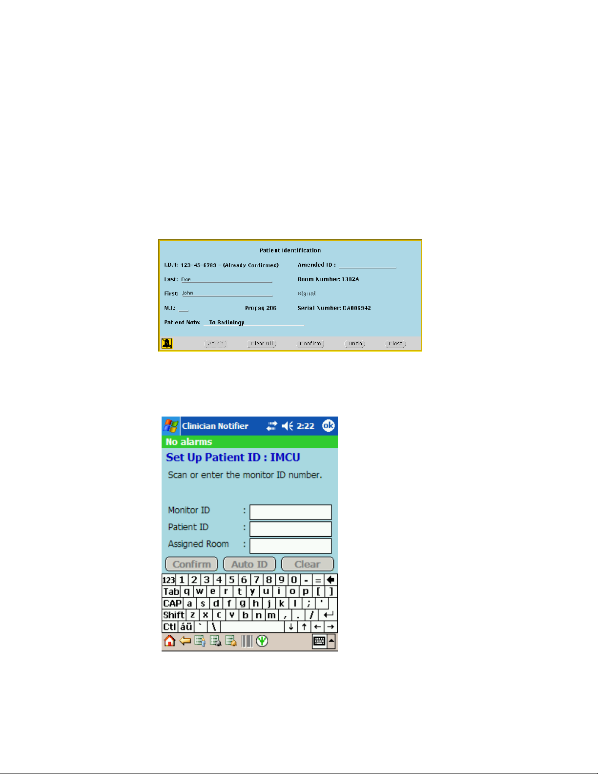
Where a patient ID number is entered
An Acuity System user enters a patient ID number in one of these two places to confirm
a new patient into the Acuity System:
• At the Acuity Central Station, in the Patient ID Setup window
• For systems that include the WACS option with the AcuityLink option, at a mobile
device running the AcuityLink Clinician Notifier program, in the Setup Patient ID
screen.
Page 48

44 Inbound ADT HL7 messages Welch Allyn Connectivity Server
Sequence of events when ID number is entered
This is the sequence of events that occurs within Acuity Systems that include the WACS
option with the Inbound HL7 ADT module.
1. In a patient ID setup window, the user enters the patient ID number or an amended
patient ID number and presses the Return or Enter key.
2. The Acuity System queries the Acuity System patient name server deamon (PNSD)
for the ID number(s) and patient information associated with the number(s).
If a match is not found, the Acuity System queries the WACS database (SQL) for the
ID number(s) and patient information associated with the number(s).
3. At the Acuity Central Station in the Patient ID Setup window, the Acuity System
responds in one of these ways:
• If no associated information was found, the curser moves to the next field in the
window.
• If associated information was found, this confirmation message appears within
two seconds.
4. The user responds in one of these ways:
• If the user clicks Accept, the remaining fields of the window autopopulate, and
existing information in the fields is replaced.
The autopopulate action cannot be undone.
• If the user clicks Go Back, the user can manually type the correct information into
the blank text fields.
5. The user clicks Confirm.
The patient information is distributed and confirmed.
Page 49

Programmer’s Guide Inbound ADT HL7 messages 45
Rules regarding Acuity System patient IDs
These rules apply within the Acuity System:
• A patient ID number, an amended ID number or both may be entered.
• Letter case is ignored when ID numbers are compared to the PSND and WACS
databases.
• An autopopulate search can match a currently monitored Acuity System patient or a
patient discharged from the Acuity System for a period of 24-96 hours (depending
upon the system’s Full Disclosure configuration).
• After autopopulated information is confirmed, it can be modified. ID numbers can be
revised with an amended ID number, and amended ID numbers can be amended.
For more information about entering and revising patient information in the Acuity
System, see the Acuity and Mobile Acuity LT Central Monitoring Systems directions
for use.
Page 50

46 Inbound ADT HL7 messages Welch Allyn Connectivity Server
ADT messages accepted and stored by WACS
WACS accepts the message types and formats described in this section.
Accepted message types
WACS receives and stores these types of messages. Welch Allyn suggests that you
consider configuring your CIS/HIS ADT server to block messages other than these.
• ADT/ACT - Admit/visit notification (event A01)
• ADT/ACK - Discharge/end visit (event A03)
• ADT/ACK - Register a patient (event A04)
• ADT/ACK - Pre-admit a patient (event A05)
• ADT/ACK - Update patient information event (event A08).
• ADT/ACK - Cancel admit/visit notification (event A11)
• ADT/ACK - Cancel discharge/end visit (event A13
)
Note
The Acuity System accepts middle initial only (not middle name) in messages.
Accepted message formats
WACS accepts standard HL7 2.3-2.4 delimiters and data types, as defined in this section,
taken from the Health Level Seven Implementation Support Guide for HL7 Standard
Version 2.3.
Delimiters
The interface parses incoming messages for delimiters, and the delimiters might differ in
each message.
This section enables you to select and document which delimiters will be used in your
interface, and to identify related issues early (for example, conflicts with ASCII characters
that have special meaning in EBCDIC).
Table 22. Delimiters
Segment terminator <CR> <CR> <CR>
Field separator | (hex 0D)
Component separator ^
Sub-component separator &
Repetition Separator ~
Escape Character \
HL7 System A System B
Page 51

Programmer’s Guide Inbound ADT HL7 messages 47
Data types
The HL7 Standard allows for different data formats for each of the following data types.
This section documents general attributes of each data format.
Table 23. Data type descriptions
Data type Definition Data format attributes and notes
Alphanumeric
ST String
TX Text data
FT Formatted text
Numerical
CQ Composite quantity with units <quantity (NM)> ^ <units (CE)>
MO Money <quantity (NM)> ^
NM Numeric
SI Sequence ID
SN Structured numeric <comparator> ^ <num1 (NM)>
Identifier
IS Coded values for
HL7 tables
IS Coded value for user-defined tables
HD Hierarchic designator <namespace ID (IS)> ^
EI Entity identifier <entity identifier (ST)> ^
RP Reference pointer <pointer (ST)>^<application
PL Person location <point of care (IS)> ^ <room
PT Processing type <processing ID (ID)> ^
Date/Time
DT Date YYYY[MM[DD]]
TM Time HH[MM[SS[.S[S[S[S]]]]]][+/-ZZZZ]
TS Time stamp YYYY[MM[DD[HHMM[SS[.S[S[
<denomination (ID)>
^ <separator/suffix> ^ <num2
(NM)>
<universal ID (ST)> ^
<universal ID type (ID)>
Used only as part of EI and
other data types.
<namespace ID (IS)> ^
<universal ID (ST)> ^
<universal ID type (ID)>
ID (HD)> ^ <type of data (ID)>
^ <subtype (ID)>
(IS)> ^ <bed (IS)> ^ <facility
(HD)> ^ < location status (IS
)> ^ <person location type
(IS)> ^ <building (IS)> ^ <floor
(IS)> ^ <location description
(ST)>
<processing mode (ID)>
S[S]]]]]]]][+/-ZZZZ] ^ <degree of
precision>
Page 52

48 Inbound ADT HL7 messages Welch Allyn Connectivity Server
Table 23. Data type descriptions
Data type Definition Data format attributes and notes
Code values
CE Coded element <identifier (ST)> ^ <text (ST)> ^
CF Coded element with formatted values <identifier (ID)> ^ <formatted
CK Composite ID with check digit <ID number (NM)> ^ <check
CN Composite ID number and name <ID number (ST)> ^ <family
CX Extended composite ID with check
digit
XCN Extended composite ID number and
name
Generic
CM Composite No new CM’s are allowed after HL7
<name of coding system (ST)>
^ <alternate identifier (ST)> ^
<alternate text (ST)> ^ <name
of alternate coding system
(ST)>
text (FT)> ^ <name of coding
system (ST)> ^ <alternate
identifier (ID)> ^ <alternate
formatted text (FT)> ^ <name
of alternate coding system
(ST)>
digit (NM)> ^ <code identifying
the check digit scheme
employed (ID)> ^ < assigning
authority (HD)>
name (ST)> ^ <given name
(ST)> ^ <middle initial or name
(ST)> ^ <suffix (e.g., JR or III)
(ST)> ^ <prefix (e.g., DR)
(ST)> ^ <degree (e.g., MD)
(ST)> ^ <source table (IS)> ^
<assigning authority (HD)>
<ID (ST)> ^ <check digit (ST)>
^ <code identifying the check
digit scheme employed (ID)> ^
< assigning authority (HD) )> ^
<identifier type code (IS)> ^ <
assigning facility (HD)
In Version 2.3, use instead of
the CN data type. <ID number
(ST)> ^ <family name (ST)> ^
<given name (ST)> ^ <middle
initial or name (ST)> ^ <suffix
(e.g., JR or III) (ST)> ^ <prefix
(e.g., DR) (ST)> ^ <degree
(e.g., MD) (ST)> ^ <source
table (IS)> ^ <assigning
authority (HD)> ^ <name type
code (ID)> ^ <identifier check
digit (ST)> ^ <code identifying
the check digit scheme
employed (ID)> ^ <identifier
type code (IS)> ^ <assigning
facility (HD)>
Version 2.2. Hence there are no new
CM’s in Version 2.3.
Page 53

Programmer’s Guide Inbound ADT HL7 messages 49
Table 23. Data type descriptions
Data type Definition Data format attributes and notes
Demographics
AD Address <street address (ST)> ^ < other
PN Person name <family name (ST)> ^ <given
TN Telephone number [NN] [(999)]999-
XAD Extended address In Version 2.3, replaces the AD
XPN Extended person name In Version 2.3, replaces the PN
XON Extended composite name and ID
number for organizations
XTN Extended telecommunications
number
designation (ST)> ^ <city (ST)>
^ <state or province (ST)> ^
<zip or postal code (ST)> ^
<country (ID)> ^ <address type
(ID)> ^ <other geographic
designation (ST)>
name (ST)> ^ <middle initial or
name (ST)> ^ <suffix (e.g., JR
or III) (ST)> ^ <prefix (e.g., DR)
(ST)> ^ <degree (e.g., MD)
(ST)>
9999[X99999][B99999][C any
text]
data type. <street address
(ST)> ^ <other designation
(ST)> ^ <city (ST)> ^ <state or
province (ST)> ^ <zip or postal
code (ST)> ^ <country (ID)> ^
< address type (ID)> ^ <other
geographic designation (ST)> ^
<county/parish code (IS)> ^
<census tract (IS)>
data type. <family name (ST)>
^ <given name (ST)> ^ <middle
initial or name (ST)> ^ <suffix
(e.g., JR or III) (ST)> ^ <prefix
(e.g., DR) (ST)> ^ <degree
(e.g., MD) (ST)> ^ <name type
code (ID) >
<organization name (ST)> ^
<organization name type code
(IS)> ^ <ID number (NM)> ^
<check digit (NM)> ^ <code
identifying the check digit
scheme employed (ID)> ^
<assigning authority (HD)> ^
<identifier type code (IS)> ^
<assigning facility ID (HD)>
In Version 2.3, replaces the TN
data type. [NNN] [(999)]9999999 [X99999] [B99999] [C any
text] ^ <telecommunication
use code (ID)> ^
<telecommunication equipment
type (ID)> ^ <email address
(ST)> ^ <country code (NM)> ^
<area/city code (NM)> ^
<phone number (NM)> ^
<extension (NM)> ^ <any text
(ST)>
Page 54

50 Inbound ADT HL7 messages Welch Allyn Connectivity Server
Table 23. Data type descriptions
Data type Definition Data format attributes and notes
Specialty
Waveform
CD Channel definition <channel identifier (*)> ^
MA Multiplexed array <sample 1 from channel 1
NA Numeric array <value1 (NM)> ^ <value2
ED Encapsulated data Supports ASCII MIMEencoding
Price data
CP Composite price In Version 2.3, replaces the
Patient administration/Financial information
FC Financial class <financial class (ID)> ^
Extended queries
QSC Query selection criteria <name of field (ST)> ^
QIP Query input parameter list <field name (ST) > ^ <value1
RCD Row column definition <HL7 item number (ST)> ^
<channel number (NM)> &
<channel name (ST)>> ^
<electrode names (*) > ^
<channel sensitivity/units (*) >
^ <calibration parameters (*)> ^
<sampling frequency (NM)> ^
<minimum/maximum data
values (*)>
(NM)> ^ <sample 1 from
channel 2 (NM)> ^ <sample 1
from channel 3 (NM)>
...~<sample 2 from channel 1
(NM)> ^ <sample 2 from
channel 2 (NM)> ^ <sample 2
from channel 3 (NM)> ...~
(NM)> ^ <value3 (NM)> ^
<value4 (NM)> ^ ...
of binary data.
<source application (HD) > ^
<main type of data (ID)> ^
<data subtype (ID)> ^
<encoding (ID)> ^ <data (ST)>
MO data type. <price (MO)> ^
<price type (ID)> ^ <from value
(NM)> ^ <to value (NM)> ^
<range units (CE)> ^ <range
type (ID)>
<effective date (TS)>
<relational operator (ID)> ^
<value (ST)> ^ <relational
conjunction (ID)>
(ST) & value2 (ST) & value3
(ST) ...>
<HL7 data type (ST)> ^
<maximum column width
(NM)>
Page 55

Programmer’s Guide Inbound ADT HL7 messages 51
Table 23. Data type descriptions
Data type Definition Data format attributes and notes
Master files
DLN Driver’s license number <license number (ST)> ^
JCC Job code/class <job code (IS)> ^ <job class
VH Visiting hours <start day range (ID)> ^ <end
Medical records/Information management
PPN Performing person time stamp <ID number (ST)> ^ <family
Time series
DR Date/time range <range start date/time (TS)> ^
RI Repeat interval <repeat pattern (IS)> ^ <explicit
SCV Scheduling class value pair <parameter class (IS)> ^
TQ Timing/Quantity <quantity (CQ)> ^ <interval (*)>
<issuing state, province,
country (IS)> ^ <expiration date
(DT)
(IS)>
day range (ID)> ^ <start hour
range (TM)> ^ <end hour range
(TM)>
name (ST)> ^ <given name
(ST)> ^ <middle initial or name
(ST)> ^ <suffix (e.g., JR or III)
(ST)> ^ <prefix (e.g., DR)
(ST)> ^ <degree (e.g., MD)
(ST)> ^ <source table (IS)> ^
<assigning authority (HD)> ^
<name type code(ID)> ^
<identifier check digit (ST)> ^
<code identifying the check
digit scheme employed (ID )> ^
<identifier type code (IS)> ^
<assigning facility (HD)> ^ <
date/time action performed
(TS)>
<range end date/time (TS)>
time interval (ST)>
<parameter value (IS)>
^ <duration (*)> ^ <start
date/time (TS)> ^ <end
date/time (TS)> ^ <priority
(ID)> ^ <condition (ST)> ^ <text
(TX)> ^ <conjunction (ID)> ^
<order sequencing (*)>
Page 56

52 Inbound ADT HL7 messages Welch Allyn Connectivity Server
Examples of ADT messages
WACS returns acknowledgements for accepted messages and error messages for nonaccepted messages.
Acceptable ADT/ACK message and acknowledgement
The following is an example of an A03 message and acknowledgement in HL7 version 2.3
formats.
ADT^A03 message:
<Wed Jan 14 19:34:20 2009> HL7Log Responder got message:
MSH|^~\&|REG|RMH||RMH|20090114193305.00000600||ADT^A03|2271605|P|2.3EVN|03|20090114
193305.0000-0600|||AKM1^UNREAL^STEWART
PID||2006275669|2006275669||SAMPLE^MELISSA^T||19600915193300.00000600|F||||||||||2006276
69
PV1||E|ER|1|||5002^EXAMPLE^KEVIN^P|||ER||||7|||5002^EXAMPLE^KEVIN^P|ER|1064398|WC|||||||||
N|||||||01|||||D|||20090114182049.0000-0600|20090114185400.0000-0600
ACK acknowledgement:
<Wed Jan 14 19:34:20 2009> HL7Log Responder sending message:
MSH|^~\&|WAP^WAP||||20090114193420.3160600||ACK^A03|20090114193420316e9|P|2.3
MSA|AA|2271605
Page 57

Programmer’s Guide Inbound ADT HL7 messages 53
Unacceptable ADT messages and WACS error messages
WACS returns error messages to the CIS/HIS ADT server in response to these messages:
• Message types other than A01, A03, A04, A05, A08, A011 or A13, and your system
has not been programmed to block messages other than these.
• HL7 messages containing noncompliant format. In these cases, WACS rejects the
entire content of the message.
WACS error message: non-accepted message type
WACS error message:
MSH|^~\&|||||20090203130308.435-0500||ACK|16249|P|2.4
MSA|AR|613958749|No appropriate destination could be found to which this message could be
routed.
ERR|^^^207&Application Internal Error&HL70357
ADT/ACK error message: noncompliant format
Note
The Acuity System accepts middle initial only (not middle name) in messages.
In this example, the telephone number (highlighted below in bold text) is a noncompliant
format.
ADT^A01 message:
MSH|^~\&|AccMgr|1|||20090130160820||ADT^A03|6139110482|P|2.3.1EVN|A03|20090130160819
PID|1|841940^^^AccMgr^PN|500138979^^^AccMgr^MR^1||SAMPLE^PATIENT^L||19920722|F|T
EST TEST|W|2001 SAMPLE
RD^^SAMPLE^NY^132110000^^M|31|8005551212||E|S|NO|6943809^^^AccMgr^VN^1|099809
553|||2|USA||||NOT A VETERAN|||N
PV1|1|O|2E^237^02^1|3||2E^237^02|1370^TEST^TEST^^^^^^AccMgr^^^^CI|1370^ TEST ^
TEST ^^^^^^AccMgr^^^^CI||TWM||||1|||1370^
WESTPFAL^EDITH^^^^^^AccMgr^^^^CI|67|6943809^^^AccMgr^VN^1|200^TEST||||||||||||||||1|1||
1||P|||20081008111700|20081009180000|3083.9|3083.9||||0
PV2||SOB^NO||||||20081008111700
WACS error message:
MSH|^~\&|||||20090130160831.875-0500||ACK|5804|P|2.4
MSA|AE|6139110482|The phone number component must be supplied and should be in the
following format [999-9999].
ERR|^^^207&Application Internal Error&HL70357
Page 58

54 Inbound ADT HL7 messages Welch Allyn Connectivity Server
Reconfiguration of ADT services
If your WACS system receives inbound ADT messages from your CIS, and you need to
reconfigure certain ADT service settings, such as the CIS server IP address or the CIS
server port number, please contact Welch Allyn Technical Services (see “Contact
information” on page 57).
A Technical Service representative can help you access ADT settings in the WACS
program’s HL7 - General Settings page (shown below), which is beneath the WACS HL7
Manager tab. ADT settings in this page are only visible to Welch Allyn personnel.
You can access the WACS program via certain internet browsers on any computer in your
facility’s intranet. For instructions on accessing the WACS HL7 Manager pages, see the
Welch Allyn Connectivity Server (WACS) Directions for Use.
Note
If Welch Allyn personnel assist you in accessing certain ADT settings, do not
change ADT settings beyond those with which you are assisted. Changing other
ADT settings can render the WACS system inoperable.
A.
B.
C.
A. CIS server IP address used for inbound ADT messages to WACS
B. CIS server port used for inbound ADT messages to WACS
C. WACS enabled listening for CIS ADT data
Page 59

55
7
XML interface
The optional Third-Party Data Stream Interface option provides a means of moving patient
identification and patient numeric data between the Acuity Central Station and a facility’s
information system.
To receive XML messages from WACS, a CIS/HIS opens a TCP/IP socket and listens.
When the Welch Allyn Connectivity Server detects an event, it connects to the socket and
sends a message.
The interface provides the following parameters:
Table 24. XML interface parameters
Parameter Content Note
Command Set
Reset
SourceID [Patient ID or
Amended ID]
Sensitivity Lethal
High
Parameter
ApplicationID Welch Allyn
When the alarm starts.
When the alarm ends.
Acuity uses this as the unique patient identifier across
the Acuity network.
Text [free-format text] Alarm type. A valid alarm string (e.g., Heart Rate 250).
MessageID Event ID For WACS internal use only.
Timestamp [time of the alarm]
GuestName [Full name of the patient]
GuestPhysicalLocation [Assigned location of the patient] Unit and room number.
Parameter [Model name and serial number of
DestinationList [Target recipient ID] Present only if:
the alarming monitor]
- Clinician Notifier option is licensed
- Event Delivery Mode = Escalation
- At least one Primary Respondent assigned
Page 60

56 XML interface Welch Allyn Connectivity Server
For example:
<?xml version="1.0" encoding="UTF-8"?>
<Emergin Version="7.0">
<Command>Set</Command>
<SourceID>MRN-0001</SourceID>
<Sensitivity>Lethal</Sensitivity>
<ApplicationID name="WelchAllyn"/>
<Text>Asystole</Text>
<MessageID>EVENT-001</MessageID>
<Timestamp>June 4, 2006 14:25:03</Timestamp>
<GuestName>Jon L. Doe</GuestName>
<GuestPhysicalLocation>Zone1 101A</GuestPhysicalLocation>
<Parameters>Propaq 202, DA005491</Parameters>
<DestinationList>
<DestinationID>Nurse1</DestinationID>
</DestinationList>
</Emergin>
<?xml version="1.0" encoding="UTF-8"?>
<Emergin Version="7.0">
<Command>Reset</Command>
<ApplicationID name="WelchAllyn"/>
<MessageID>EVENT-001</MessageID>
<DestinationList>
<DestinationID>Nurse1</DestinationID>
</DestinationList>
</Emergin>
Page 61

57
8
Contacts and specifications
Contact information
If you encounter a problem that cannot be corrected by ordinary operating procedures
described in this manual, please contact Welch Allyn Technical Services:
Phone (within the U.S.A.): 1-800-289-2501
Phone (worldwide): +1 503-530-7500, ask for Technical Service
Fax: +1 503-526-4970
email: solutions@welchallyn.com
Internet: http://www.welchallyn.com/support/default.htm
Specifications
General WACS
Table 25. WACS 2.6x compatibility
Acuity System Component Software version compatible with WACS 2.6x
Acuity Central Monitoring System
WACS Web Server option
Operating systems/browser combinations
supported by WACS
WACS AcuityLink Clinician Notifier option 1.4x and later
Table 26. WACS Hardware
Rackmount server
Video card: none
Display: none
Ethernet interfaces (IP addresses): multiple; one connected to the Acuity System network, one to the facility network
Wireless LAN: none, no wireless card
Electromagnetic compliance: Refer to the Acuity and Mobile Acuity LT Central Monitoring Systems Directions for Use
8.2x
Windows XP (SP 1.2)/Microsoft Internet Explorer 6.x and 7.x, Firefox 2,
Firefox 3
Page 62

58 Contacts and specifications Welch Allyn Connectivity Server
WACS HL7 Interface option
Outbound messaging
Table 27. Configuration variables under HL7 tab
HL7 Manager page Default setting Alternate settings
Numeric data filter Median (can be mean for
Numeric data filter for NIBP Closest (most recent) Median (can be mean for
HL7 - General Settings page
HL7 versions supported 2.4 2.31, 2.3
Allow observations for multiple patients in one HL7 message Off On
Number of seconds to be retrieved when a new patient is
connected
Allow multiple observations for a patient in one HL7 message Off On
Number of times the server will try to send an HL7 message to
client before disconnecting
Message delay (seconds) (for push) 420 Field entry allowed
HL7 - Push on Event Settings page
Each vital sign listed in page Off On
HL7 - Observation Identifiers page
Vital-sign labels As listed in page Field entry allowed
even number of samples)
7200 Field entry allowed
5 Field entry allowed
Closest (most recent)
even number of samples)
Table 28. Non-supported features
Simultaneous clients: WACS sends data to only one CIS
HL7 batch processing: WACS only sends data at a regular interval or in response to a query
Wildcards: WACS does not accept wildcards
Page 63

Index
59
A
ADT
acceptable messages from 52
data types accepted from 47
erroneous messages 52
HL7 messages 41
how Acuity System uses information 43
message formats accepted from 46
WACS messaging rules 44
C
CIS ADT messages 41
configuring HL7 interface 5
D
Data
interface 6
transfer and storage in Acuity System 7
types accepted 47
Delimiters, accepted HL7 46
documents, related 3
E
entry sequence 44
where entered in system 43
Inbound HL7 ADT Data module 41
Interface, data 6
M
Message
ADT error, sent by WACS 52
ORU/ACK example 29
QBP^RSP example 39
QBP/RSP example 35, 37
QRY/ORF example 32, 36, 38
time/date example 13
types and formats received by WACS 46
O
Outbound HL7 Vital-sign Observations module 15
Overview, system 5
P
Patient ID
entry sequence 44
where entered in system 43
Error messages sent by WACS 52
F
Formats, accepted HL7 message 46
H
Health Level Seven Standard 11
Help 57
HL7
configuration by qualified personnel 2
interface, configuring 5
I
ID
S
segment-level protocol, HL7 12
server 5
specifications 57
T
Technical Service, Welch Allyn 57
Troubleshooting 57
V
Vital-sign Observation module, Outbound HL7 15
Page 64

60 Index Welch Allyn Connectivity Server
W
WACS
Help 57
troubleshooting 57
warning 2
Welch Allyn, Technical Service 57
X
XML interface 55
 Loading...